

Page 1
33
16
36
34
11
35
31
30
37
14
38
1
39
2
20
21
23
22
24
28
29
11
32
Serial Number
5
4
3
27
25
26
16
17
10
8
7
6
13
11
12
15
9
Shown from
opposite side.
4
15
19
18
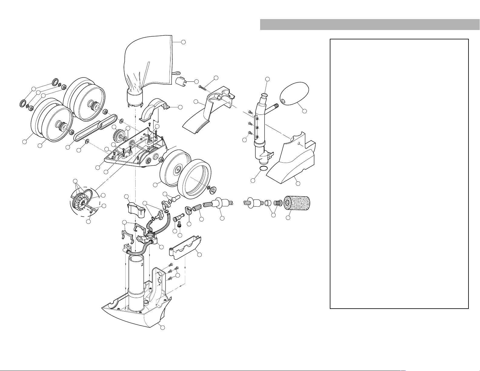
No. Part# Description Qty.
19-100-1014All Purpose Bag 1
29-100-1152Housing, Turbine Upper 1
39-100-1114Hub Cap 3
49-100-5107E-clip, Stainless Steel 10
59-100-1108Ball Bearing 8
6C-10Tire, White 3
79-100-1008Wheel, Double-side 2
89-100-1017Belt Kit, Small and Large 1
99-100-7011Shield, Bearing 3
10 9-100-1005 Frame, Exchange Only 1
11 9-100-5117 Screw, 8-32 x 3/8" S/S Pan Head 11
12 9-100-1139 Axle Block Assembly 2
13 9-100-1010 Belt Divider, Transfer Pulley 1
14 B-25 Orifice Tip with Orifice Tip Guard 1
15 9-100-1007 Transfer Pulley/Drive Shaft Assembly 1
16 9-100-5115 Screw, 8-32 x 3/4" S/S Pan Head 5
17 9-100-5130 Lock Washer, Axle Block 4
18 9-100-1132 Drive Train Gear Kit w/Turbine Bearing 1
19 9-100-1103 Turbine Wheel with Bearing 1
20 9-100-1116 Wheel, Single-side 1
21 C-131 Thrust Jet Kit 1
22 9-100-7008 Sweep Hose Barb Complete 1
23 B-20 Adjustment Screw, Sweep Hose 1
24 B-15 Sweep Hose Attach Clamp, White 1
25 9-100-9004 Base Weight 1
26 9-100-7170 Hose Clamp for WMS 6
27 9-100-7009 Jet Retainer 2
28 9-100-7010 Water Management System (WMS) 1
29 9-100-1155 Housing, Turbine Lower 1
30 9-100-3105 Sweep Hose Scrubber 1
31 9-100-5132 O-ring, In-head Timer/Feed Pipe Assy 1
32 9-100-7016
Base Assy for In-line Back-up Valve, White
1
33 9-100-1141 Top Cover, Double Wheel Side 1
34 9-100-7003 Feed Pipe/Timer Blank Assembly 1
35 A-20 Float, Head 1
36 9-100-1140 Top Cover, Single Wheel Side 1
37 B-5 Sweep Hose Complete 1
38 B-10 Wear Rings 8
39 9-100-1018 Bag Collar 1
To insure proper operation and long life for the Polaris, be sure to
insist on genuine Polaris parts.
380 EXPLODED PARTS DIAGRAM
i
Page 2
To insure proper operation and long life for the Polaris, be sure to
insist on genuine Polaris parts.
*Not sold separately.
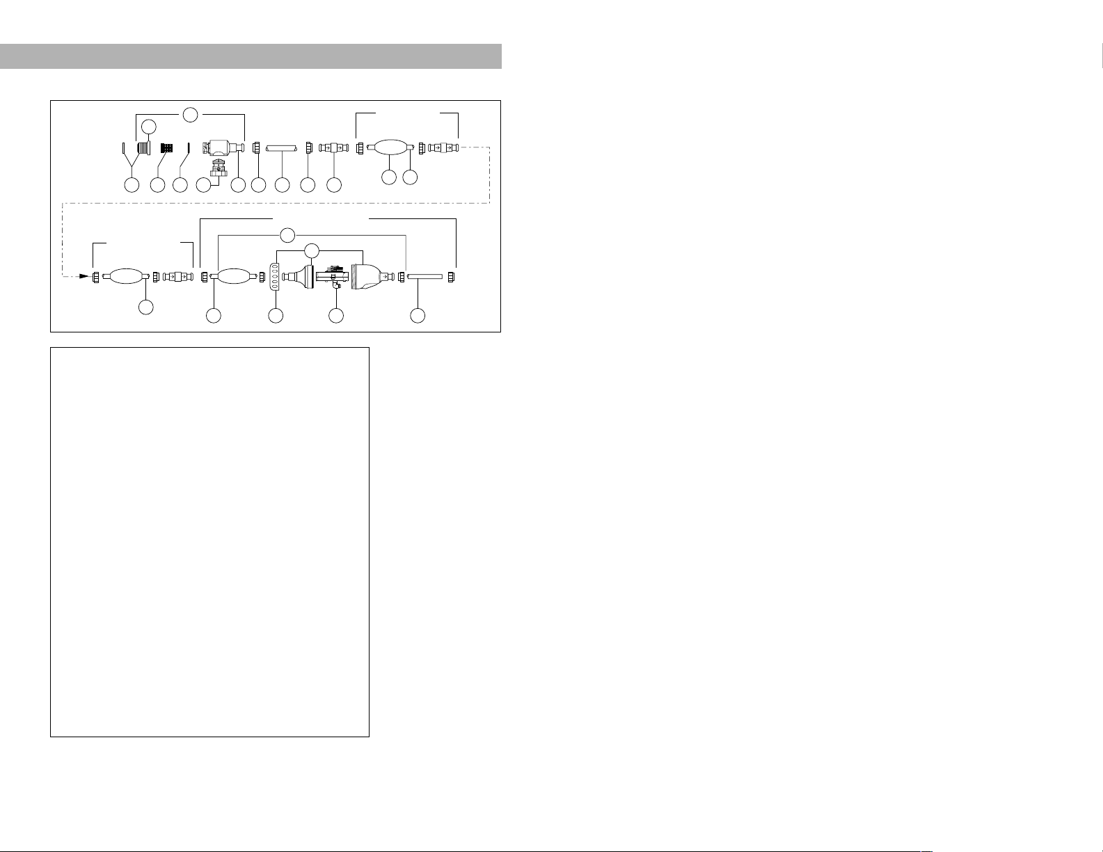
380 HOSE PARTS DIAGRAM
No. Part# Description Qty.
40 9-100-9001 UWF Connector Assembly 1
41 10-108-00 UWF Restrictor Kit 1
42 6-500-00 Universal Wall Fitting (UWF) 1
43 6-504-00 Filter Screen, UWF/QD 1
44 6-505-00 O-ring, UWF/QD 1
45 9-100-9002 Pressure Relief Valve, Black 1
46 D-29 Quick Disconnect, UWF 1
47 D-15 Nut, Feed Hose 10
48 * Adapter Hose, 8-1/2" 1
49 D-20 Swivel, Ball Bearing 3
50 D-10 Float, Feed Hose 9
51 D-45 Feed Hose, White, 10 Foot, Hard 2
52 D-50 Feed Hose, Clear, 10 Foot, Soft 1
53 G-52 Back-up Valve Kit 1
54 G-54 Case Kit for G-52 1
55 G-57 Collar, Back-up Valve 1
56 G-53 Mechanism for G-52 1
Parts Not Shown
G-5 Feed Hose Complete w/UWF,
No Back-up Valve
G-9 Coupling, 1 1/2" NPTF x 3/4" NPTM
9-100-3104 Feed Hose with Floats, White
9-100-3108 Feed Hose with Floats, Clear
9-100-9003 Street Ell
ii
iii
40
42
Pool
Wall
45 46444341 47 48 47 49
10-foot Clear Hose
Second 10-foot
White Hose
51
52
53
54
55 56
First 10-foot
White Hose
50 51
52
To The
Polaris
Page 3
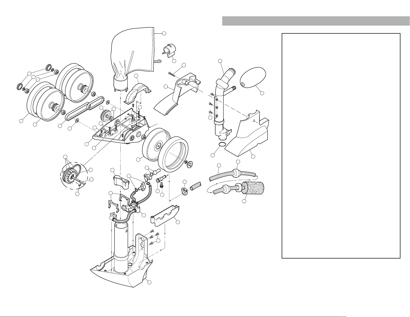
No. Part# Description Qty.
19-100-1014All Purpose Bag 1
29-100-1152Housing, Turbine Upper 1
39-100-1114Hub Cap 3
49-100-5107E-clip, Stainless Steel 10
59-100-1108Ball Bearing 8
6C-10Tire, White 3
79-100-1008Wheel, Double-side 2
89-100-1017Belt Kit, Small and Large 1
99-100-7011Shield, Bearing 3
10 9-100-1005 Frame, Exchange Only 1
11 9-100-5117 Screw, 8-32 x 3/8" S/S Pan Head 11
12 9-100-1139 Axle Block Assembly 2
13 9-100-1010 Belt Divider, Transfer Pulley 1
14 9-100-3135 Collar, Bag Tie 1
15 9-100-1007 Transfer Pulley/Drive Shaft Assembly 1
16 9-100-5115 Screw, 8-32 x 3/4" S/S Pan Head 5
17 9-100-5130 Lock Washer, Axle Block 4
18 9-100-1132 Drive Train Gear Kit w/Turbine Bearing 1
19 9-100-1103 Turbine Wheel with Bearing 1
20 9-100-1116 Wheel, Single-side 1
21 C-131 Thrust Jet Kit 1
22 9-100-7008 Sweep Hose Barb Complete 1
23 B-20 Adjustment Screw, Sweep Hose 1
24 B-15 Sweep Hose Attach Clamp 1
25 9-100-3005 Base Weight 1
26 9-100-7170 Hose Clamp for WMS 6
27 9-100-7009 Jet Retainer 2
28 9-100-7014 Water Management System (WMS) 1
29 9-100-1155 Housing, Turbine Lower 1
30 9-100-3105 Sweep Hose Scrubber 1
31 9-100-5132 O-ring, In-head Timer/Feed Pipe Assy 1
32 9-100-7016
Base Assy for In-line Back-up Valve, White
1
33 9-100-1141 Top Cover, Double Wheel Side 1
34 9-100-1002 Feed Pipe/Timer Blank Assembly 1
35 A-20 Float, Head 1
36 9-100-1140 Top Cover, Single Wheel Side 1
37 9-100-1011 Sweep Hose Complete 1
38 B-10 Wear Rings 7
To insure proper operation and long life for the Polaris, be sure to
insist on genuine Polaris parts.
360 EXPLODED PARTS DIAGRAM
iv
v
14
33
16
36
34
11
35
31
2
20
21
23
22
24
28
29
11
32
Serial Number
5
4
3
27
25
26
16
17
10
8
7
6
13
11
12
15
9
1
Shown from
opposite side.
4
15
19
18
37
38
30
Page 4
To insure proper operation and long life for the Polaris, be sure to
insist on genuine Polaris parts.
*Not sold separately.
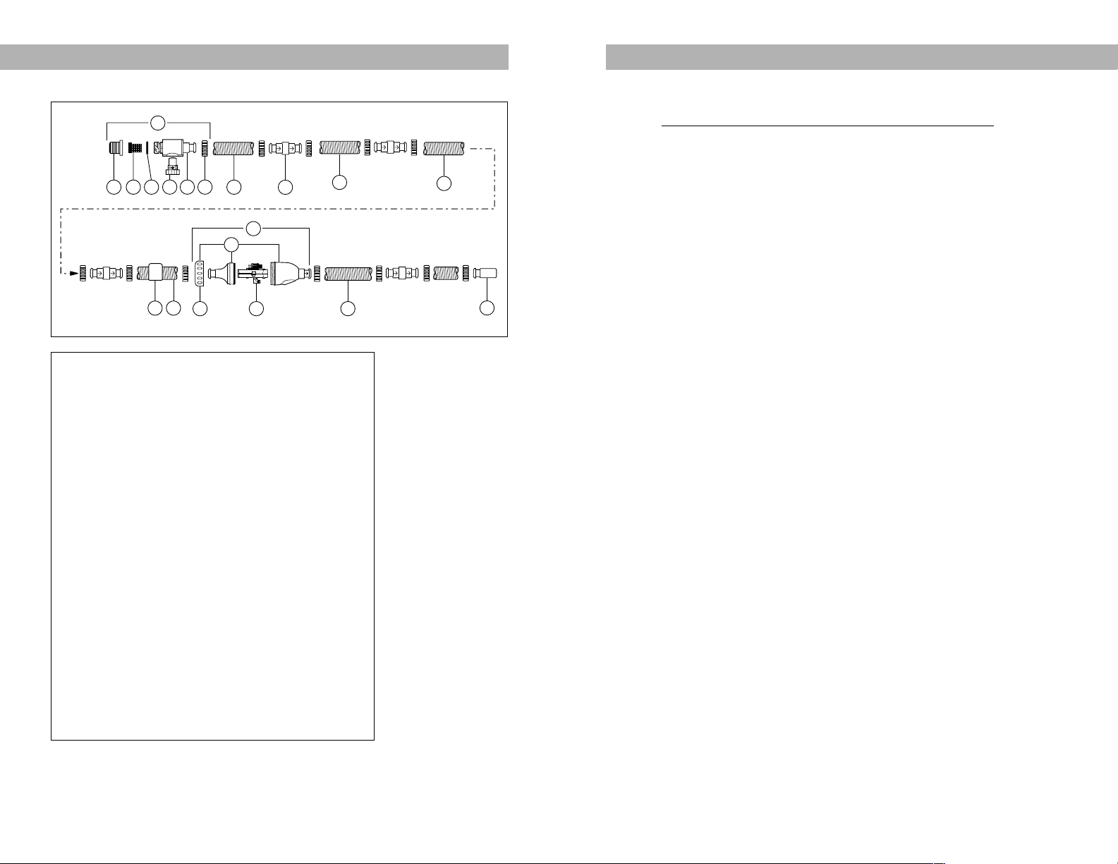
360 HOSE PARTS DIAGRAM
No. Part# Description Qty.
39 9-100-3008 UWF Connector Assembly 1
40 6-500-00 Universal Wall Fitting, UWF 1
41 6-504-00 Filter Screen, UWF/QD 1
42 6-505-00 O-ring, UWF/QD 1
43 9-100-3009 Pressure Relief Valve, White 1
44 9-100-3006 Quick Disconnect, UWF 1
45 9-100-3109 Hose Nut 12
46 9-100-3102 Feed Hose, 6 Foot 4
47 9-100-3002 Swivel, Hose 4
48 9-100-1206 Float, Feed Hose 3
49 9-100-1200 In-line Back-up Valve 1
50 9-100-1202 Case Kit, In-line Back-up Valve 1
51 G-57 Collar, Back-up Valve 1
52 9-100-1204 Mechanism, In-line Back-up Valve 1
53 9-100-3103 Feed Hose, 1 Foot 1
54 * Pressure Tester 1
Parts Not Shown
9-100-3100 Feed Hose Complete w/UWF,
No Back-up Valve
9-100-9003 Street Ell
vi
vii
REPLACEMENT PARTS TO STOCK
All parts are interchangeable between the 380 and 360 except where noted.
Name Part #
Polaris 380/360 Tune-up Kit 9-100-9010
Polaris 380 Rebuild Kit 9-100-9030
Polaris 360 Rebuild Kit 9-100-9060
380 In-line Back-up Valve Conversion Kit 9-100-9040
360 In-line Back-up Valve Conversion Kit
9-100-3200
360 Pressure Gauge Kit 9-100-6400
360 In-line Back-up Valve Case Kit 9-100-1202
*All Purpose Bag 9-100-1014
*Wheel, Single-side 9-100-1116
*Wheel, Double-side 9-100-1008
*Transfer Pulley/Drive Shaft Assembly 9-100-1007
*Axle Block Assembly 9-100-1139
*Drive Train Gear Kit w/Turbine Bearing 9-100-1132
*Belt Kit, Small and Large 9-100-1017
*Sweep Hose Scrubber 9-100-3105
*Tire, White C-10
*E-clip, Stainless Steel 9-100-5107
*O-ring, In-head Timer/Feed Pipe Assy. 9-100-5132
*Hub Cap 9-100-1114
*Ball Bearing 9-100-1108
*Hose Clamp for WMS 9-100-7170
*Housing, Turbine Upper 9-100-1152
*Shield, Bearing 9-100-7011
**380 Back-up Valve Kit G-52
**380 Base Weight 9-100-9004
**Jet Retainer 9-100-7009
**Sweep Hose Attach Clamp, White B-15
**Feed Pipe/Timer Blank Assembly 9-100-7003
**380 Sweep Hose Complete B-5
**Adjustment Screw, Sweep Hose B-20
**Thrust Jet Kit C-131
**Top Cover, Single Wheel Side 9-100-1140
**Top Cover, Double Wheel Side 9-100-1141
**Housing, Turbine Lower 9-100-1155
**Sweep Hose Barb Complete 9-100-7008
**380 Water Management System 9-100-7010
39
Pool
Wall
43
45
40 41
44
42
46
48
51
46
50
47
49
52
46
53
46
To
The
Polaris
54
Page 5

TABLE OF CONTENTS
Diagrams
380 Exploded Parts Diagram..................................i
380 Hose Parts Diagram........................................ii
360 Exploded Parts Diagram................................iv
360 Hose Parts Diagram.......................................vi
Replacement Parts to Stock.....................................vii
I. Introduction ................................................................2
Serviceman’s Tools ...............................................2
II. Installation Basics
380 Installation Basics...........................................3
360 Installation Basics...........................................6
III. Head Adjustments and Functions............................10
IV. Troubleshooting Over the Phone.............................11
V. Troubleshooting On the Bench ................................14
VI. Troubleshooting Procedures Poolside
380 Poolside Procedures ....................................17
360 Poolside Procedures ....................................18
VII. Problem/Solution Troubleshooting ........................20
VIII. How to Check and Service ......................................25
A. Pressure ..........................................................25
B. Wheel RPM .....................................................26
C. Water Flow Diagram .......................................28
D. Jets..................................................................29
E. Drive Jet ..........................................................29
F. In-line Back-up Valves ....................................32
G. In-head Back-up Timer ...................................31
H. Converting an In-head Timer to an
In-line Back-up Valve ......................................32
I. Drive Train.......................................................33
J. Hose Length....................................................34
IX. Part Removal and Replacement..............................35
A. Single-side Wheel ...........................................35
B. Drive Train Removal & Replacement .............35
C. Double-side Wheels........................................36
D. Drive Belts.......................................................37
E. Water Management System ...........................38
F. Frame Exchange.............................................38
G. Transfer Pulley/Drive Shaft Assembly............39
H. Gear Kit ...........................................................40
X. Polaris Booster Pump ..............................................41
A. Exploded Parts Diagram .................................41
B. Installation Basics ...........................................42
C. Problem/Solution Troubleshooting .................43
D. Seal Replacement...........................................45
XI. Index ........................................................................47
viii
1
**Base Assembly, White 9-100-7016
**Float, Head A-20
UWF Restrictor Kit 10-108-00
Float, Feed Hose D-10
Wear Rings B-10
Universal Wall Fitting 6-500-00
Mender Nut, Feed Hose D-15
Swivel, Ball Bearing D-20
Filter Screen, UWF/QD 6-504-00
Quick Disconnect, UWF D-29
Pressure Relief Valve, Black 9-100-9002
Pressure Relief Valve, Red D-28
Screw (Axle Blocks, Tops) 9-100-5115
Screw 9-100-5117
In-head Timer Assembly 9-100-7006
Pump Seal P-55
Impeller P-15
Pump Motor P-61
360 Base Weight 9-100-3005
360 UWF Eyeball Fitting 6-511-00
360 Feed Hose Complete, w/UWF,
No Back-up Valve 9-100-3100
360 Feed Hose, 1 Foot 9-100-3103
360 Mechanism, In-line Back-up Valve 9-100-1204
360 Base Weight 9-100-3005
360 Collar, Bag Tie 9-100-3135
360 Water Management System 9-100-7014
360 Feed Pipe/Timer Blank Assembly 9-100-1002
*360 Sweep Hose Complete 9-100-1011
360 UWF Connecter Assembly 9-100-3008
360 Pressure Relief Valve, White 9-100-3009
360 Quick Disconnect, UWF 9-100-3006
360 Hose Nut 9-100-3109
360 Hose Feed, 6 Foot 9-100-3102
360 Hose Swivel 9-100-3112
360 Float, Feed Hose 9-100-1206
360 In-line Back-up Valve 9-100-1200
*Included in Polaris 380/360 Tune-up Kit and 380 Rebuild Kit
**Included in Polaris 380 Rebuild Kit
Page 6
I. INTRODUCTION
This handbook is designed as a quick reference guide for the service
professional to aid in identifying and correcting problems with a Polaris VacSweep® 380 or a Polaris Vac-Sweep® 360 automatic pool cleaner. Information
exclusive to the 360 is shown in blue text. As you use this handbook, please
refer to the exploded parts diagrams and the hose parts diagrams at the beginning of this book to identify part location and part numbers. If you still have questions after using this handbook, please call our Customer Service Department at
1-800-VAC-SWEEP (822-7933), Monday through Friday, 7:30am-5:00pm,
Pacific Standard Time or fax us at 1-800-479-TECH (8324).
Serviceman’s Tools
Phillips-head Screwdriver Needle-nose Pliers
Flat-blade Screwdriver 0-60 psi Pressure Gauge
Knife or Scissors Slip Joint Pliers
Tape Measure 1/2” and 9/16” Wrench
Magic Marker 1/8” Hex Wrench
Tube of Silicone Sealant Paper Clip
0-30 psi Gauge
Special Polaris Tools
Name Part #
380 Pressure Tester G-35
380 Wet Function Bench Test G-110
UWF Removal Tool, Plastic 10-102-00
UWF Removal Tool, Stainless Steel 10-104-00
360 Pressure Stick 9-100-6000
360 Wet Bench 9-100-6005
II. INSTALLATION BASICS
380 INSTALLATION BASICS Connection Points
1. Dedicated cleaner line: 1-1/2 inches female threaded wall fitting in the
midpoint of the long wall, approximately 6 inches below the water surface.
2. Over deck: Over-the-deck Kit (part #G-12) for pools without a dedicated
cleaner line.
Booster Pump
The booster pump should be installed downstream from the filter and heater,
but upstream from any air inducing equipment, solar systems and/or chlorinator. Never run the booster pump without the pool filtration pump running.
(Refer to page 41 for booster pump installation basics.)
Hose Cutting
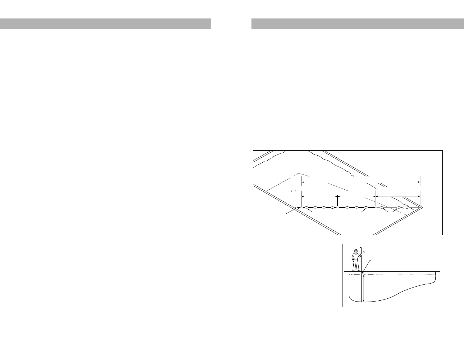
1. Straighten the feed hose by
soaking it in hot water or laying it
flat in the sun.
2. Measure and mark the deepest
part of the pool (usually the
main drain) with a telepole. If
the pool depth is 10 feet or
more, do not cut the clear
hose and skip to step 4.
2
3
Floats Are Evenly Distributed
(1-1/2 to 3 Feet Apart)
Universal Wall
Fitting
Properly Sized Feed Hose
2-3 Feet Apart
White Hoses Are Cut to Equal Lengths
Clear Hose is Equal to
Greatest Depth of Pool
Entire Feed Hose Reaches Within 6" of Farthest Point of Pool
Telepole
Mark Water Level
Greatest Depth of Pool
Page 7
10. On the clear hose, make sure
one float is against the back-up
valve on the side opposite the
cleaner and another float is
within 2-3 feet. On the white
hoses, space the floats no less
than 1-1/2 feet and no more
than 3 feet apart, so that the
white hoses do not sag. It may
be necessary to remove floats
to maintain proper spacing.
11. After the cleaner has been
connected, it is important to
check the wheel RPM:
• Mark the single-side wheel.
• Turn on the filtration and
booster pumps, and allow
the back-up valve to complete a back-up cycle.
• Hold the cleaner completely
under the water and count the wheel revolutions for one minute.
• RPM range needs to be 28-32. (If it is not, refer to page 25.)
5
3. Lay the telepole next to the
clear hose. If the clear hose is
longer than the mark on the
telepole, cut the excess from
the end attached to the white
hose. Do not cut off the float.
Reattach the clear hose to the
white hose. It is easier to reinstall the swivels when the hose
and swivels are wet.
4. Screw the universal wall fitting
into the dedicated return line.
Attach the Quick Disconnect at
the end of the white hose to the
Universal Wall Fitting.
5. Extend the hose to the farthest
point of the pool. (The Polaris
will not usually climb onto the
top step, so do not count it in
your measurement.) If the hose
is within 6 inches of the farthest
point of the pool, go to step 10
on the next page. If the hose is
more than 6 inches short, add a
10-foot section of White Feed
Hose with Floats (part #9-100-
3104), two Mender Nuts (part
#D-15), and one Swivel (part
#D-20). Do not add more
than one 10-foot hose section.
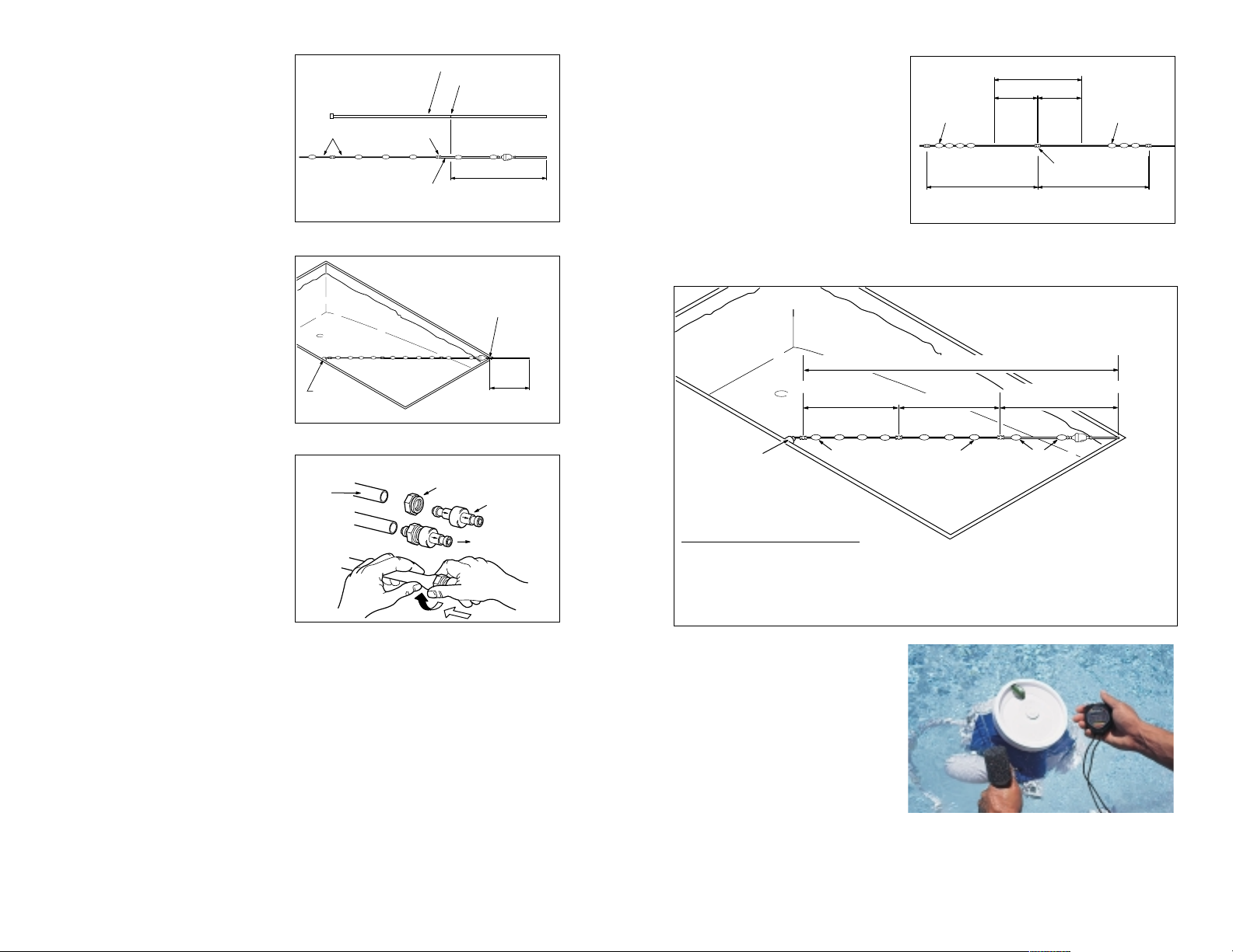
6. Measure the amount of hose that extends past the farthest point of the
pool. This is the overage measurement. Do not cut the hose yet.
7. Lay the hose on the deck. Go to the swivel between the 10-foot white
hoses. Slide the floats away from the swivel and remove the swivel.
8. Cut an equal amount of the overage measurement from each 10-foot
white hose.
9. Reinstall the swivel with the flow arrows on the swivel pointing toward the
Polaris. (Refer to the “Proper Mender Nut Placement” diagram above.)
4
Cut Clear Hose
Equal to Greatest
Depth of Pool
Water Level Mark
Telepole
SwivelWhite Hoses
Remove Excess
Hose From This
End
Feed
Hose
Mender Nut
Swivel
Water Flow
To Polaris
Proper Mender Nut Placement
Overage
Measurement
Universal
Wall
Fitting
Farthest
Point from
Universal
Wall Fitting
Overage Measurement
Remove
Here
White Hoses are
Cut to Equal Lengths
Floats
Swivel
Floats
Remove
Here
Floats Are Evenly Distributed
(1-1/2 to 3 Feet Apart)
Universal Wall
Fitting
Properly Sized Feed Hose
2-3 Feet Apart
White Hoses Are Cut to Equal Lengths
Clear Hose is Equal to
Greatest Depth of Pool
Entire Feed Hose Reaches Within 6" of Farthest Point of Pool
Feed hose is cut correctly if:
A. Clear hose is equal to greatest depth of pool.
B. Hard white hoses are equal in length.
C. Entire feed hose reaches within 6” of farthest point of pool.
D. Floats on white hoses are spaced evenly, between 1-1/2 to 3 feet apart.
Page 8
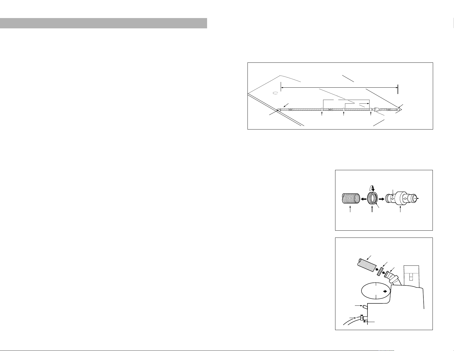
Cutting the Feed Hose
1. With the pool pump on, hold the pressure tester underwater. Pull the
hose to the farthest point of the pool. (The Polaris will not usually climb
onto the top step, so do not count it in the measurement.) If the hose just
reaches the farthest point of the pool, go to “Hooking Up the Polaris.”
2. If the hose is short of the farthest point, add an additional 6 Foot Hose
(part #9-100-3102), one Swivel (part #9-100-3002), and two Hose Nuts
(part #9-100-3109). Do not add more than one 6 foot hose.
3. If the hose extends past the farthest point of the pool, mark the excess
hose. Turn off the pump and
measure the marked amount.
4. Go to the first section of hose
from the pool wall and disconnect the hose at the swivel. Cut
off the measured amount of
excess hose. Reconnect the
hose to the swivel.
5. Double check the hose length
by repeating Step 1.
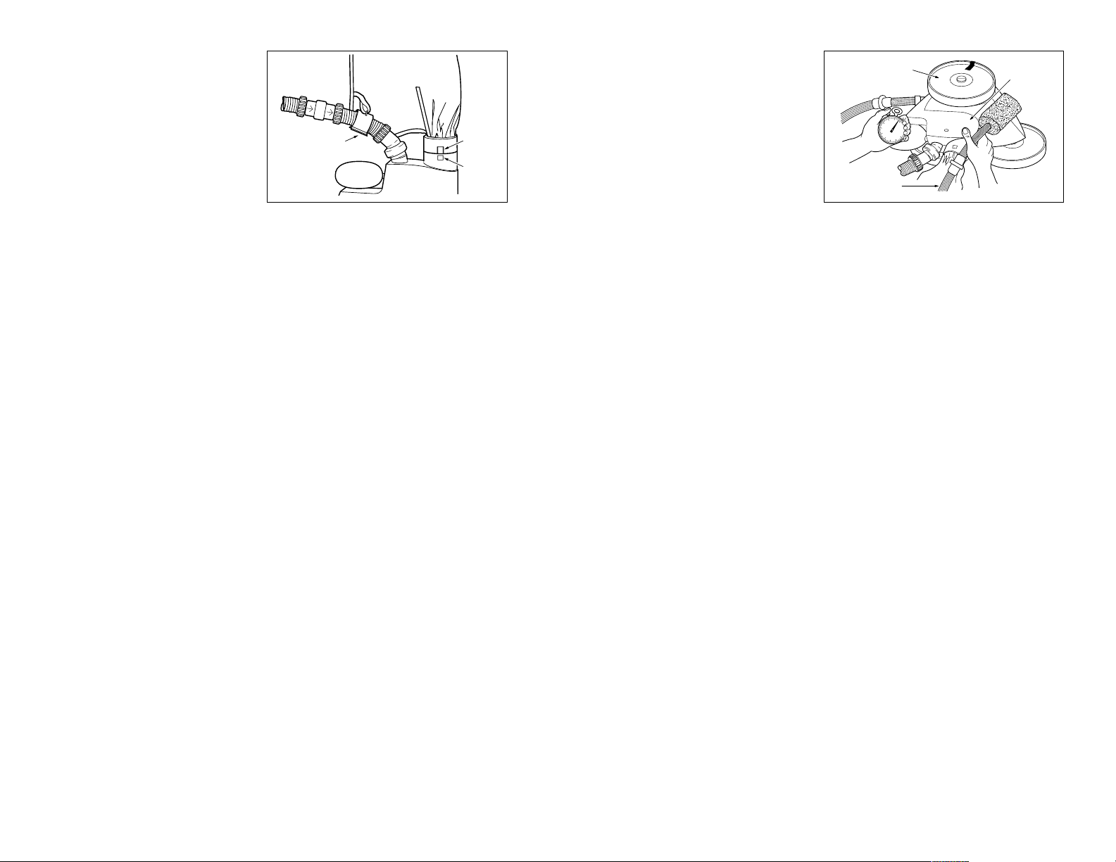
Hooking Up
the Polaris
1. Remove the pressure tester
from the hose by unscrewing
the hose nut. See the “Hose
Nut Removal” diagram above.
2. Remove the hose nut from the
pressure tester and push it onto
the feed pipe. Connect the
hose to the feed pipe with the
hose nut. If the end of the hose
7
360 INSTALLATION BASICS
Pool Connections
1. The Polaris 360 comes equipped to connect to a 1-1/2 inch female
pipe fitting on a dedicated cleaner line. An adjustable valve and pressure gauge should be installed to allow you to adjust the water flow
to the Polaris.
2. If the pool does not have a dedicated cleaner line, you may be able to
connect the Polaris 360 by using a special adapter kit. All of the kits
connect to plastic pipe only.
3. If a spa is connected to the pool filtration equipment, you may also need
to obtain some expansion regulators in addition to one of the standard
kits available. Contact our Technical Support Department at 1-800-VACSWEEP to determine what parts are necessary.
Installing the Universal Wall Fitting
1. Turn on the filtration pump and flush out the plumbing line. Then turn
pump off.
2. Remove the Universal Wall Fitting (part #6-500-00) from the Quick
Disconnect (part #9-100-3006).
3. Screw the Universal Wall Fitting into the return line by hand. Turn the
Quick Disconnect clockwise into the Universal Wall Fitting and pull away
to secure. Turn the Quick Disconnect by hand to tighten the Universal
Wall fitting; do not over tighten. Once the Universal Wall Fitting is secure,
the Quick Disconnect can be removed without removing the Universal
Wall Fitting.
Pressure Testing Instructions
1. Before installing the Polaris 360, make sure the pool filter is clean.
2. Connect the Quick Disconnect to the Universal Wall Fitting.
3. While someone holds the free end of the hose in the pool, turn on the
pool pump. Hold the free end of the hose underwater and cover the large
hole at the end of the pressure tester. Reach down and feel around the
Quick Disconnect to see if the Pressure Relief Valve (part #9-100-3009)
is releasing water. If it is, continue with “Cutting the Feed Hose.” If it isn’t,
the filtration pump may not have sufficient water pressure to operate
the Polaris.
Dedicated Line Installations: Increase flow to dedicated line until Pressure
Relief Valve releases water.
6
Feed Hose Hose Nut Swivel
Flow Arrow
To
the
Polaris
O-ring
Hose Nut Removal
1. Unscrew hose nut (reversed threads).
2. Pull hose off swivel.
Feed
Hose
Head Float
Feed
Pipe
Thrust
Jet
Sweep
Hose
Sweep Hose
Adjustment Screw
Hose
Nut
Assembling the Polaris
Universal Wall
Fitting
Entire Feed Hose Reaches Within 6" of Farthest Point of Pool*
Cut excess hose from
first section of hose
7'
Float
Float
Float
4'
Measure with pool
pump on and pressure
tester underwater
Pressure Tester
Properly Sized Feed Hose
Page 9
To avoid damaging the Polaris,
hold it by the blue top, suspended
on its side just below the water
level. Hold it away from the pool
wall with the single-wheel side
up. Hold the sweep hose to
avoid getting wet.
Count the revolutions of the
marked wheel for exactly one
minute, beginning after it has completed a back-up cycle. This gives the
wheel Revolutions Per Minute (RPM).
For proper operation, the Polaris should operate between 28 and 32
RPM. If it has less than 28 RPM, follow the instructions below.
1. Clean the Filter Screen (part #6-504-00). A dirty filter screen will
restrict the water flow to the Polaris.
2. Clean the pool skimmer, filter, and pump basket.
3. Check the hoses, connections, and swivels for leaks that could cause
loss of water pressure.
4. If an adjustable valve has been installed, adjust the valve to increase
water to the Polaris.
5. You may need to install Adjustable Eyeball Fittings (part #10-104-00)
in some returns.
If you have more than 32 RPM, unscrew the Pressure Relief Valve (part
#9-100-3009) until the proper RPM is reached. If an adjustable valve has
been installed, adjust the valve to reduce the amount of water going into
the Polaris.
9
that connects to the Polaris has
a curve to it, align it with the
curve in the feed pipe.
3. Loop the velcro strip through
the eye on the bag tie collar.
Bag tie should be attached
below the first swivel.
4. Gently place the Polaris into
the pool. Turn on the pool filtration pump.
5. Verify that the wheel RPM is between 28 and 32. Refer to “Fine Tuning
the Polaris, Checking Wheel RPM” below.
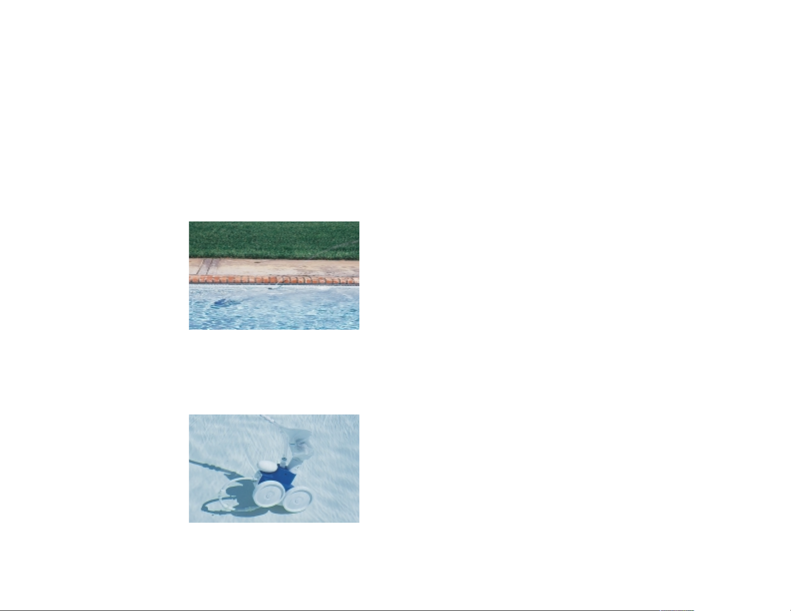
Checking Operation
Approximately every 3-1/2 minutes the Polaris 360 will go into back-up mode.
At this time the back-up valve will pull the Polaris away from potential obstacles. The sweep hose operates in a gentle sweeping motion to prevent debris
from becoming trapped in hard-to-reach corners of the pool. If the Polaris
does not travel into all areas of the pool, turn off the pool filtration pump and
make the necessary adjustments below.
Fine Tuning the Polaris
• Thrust Jet Adjustment
The thrust jet adjusts the direction of the Polaris. Its standard position is
eleven o’clock. See the “Assembling the Polaris” diagram shown on page
7for the location of the thrust jet.
•Sweep Hose Adjustment
The sweep hose should operate in a gentle sweeping motion. To decrease
the motion of the sweep hose, turn the sweep hose adjustment screw
clockwise. Make sure the Sweep Hose Scrubber (part #9-100-3105) is not
blocking the water flowing out the end of the sweep hose. See the
“Assembling the Polaris” diagram on page 7.
• Checking the Wheel RPM
To determine whether the Polaris is receiving proper water pressure, turn
off and carefully remove the Polaris from the pool. Mark the outer edge
of the tire on the single-wheel side of the Polaris. Place the Polaris back
into the pool and turn on the filtration pump.
8
Bag Tie Collar
Prong
Square
Hole
Single-wheel Side
Blue
Top
Sweep Hose
Page 10
IV. TROUBLESHOOTING OVER THE PHONE
The following topics should be discussed to aid you in troubleshooting a
Polaris 380 or Polaris 360 over the phone. By asking specific questions, you
should be able to identify the cause of a problem before the cleaner is
brought in to be serviced. For the best results, follow the topics in order. If the
cleaner must come in for repair, request that the feed hose also be brought in
for evaluation.
With the Cleaner On:
Topic Recommendation
1. Verify the wheel RPM It should be between 28 and 32. (Remember,
the poolowner needs to hold the cleaner com
pletely under the water when counting the
wheel RPM.)
If it’s too high–For 380: Replace the blue UWF restrictor with the red
UWF restrictor. If that does not correct the
wheel RPM, unscrew the pressure relief valve.
For 360: For dedicated cleaner line, adjust the clean-
er line valve or open the pressure relief
valve. For return line installations, open up
the holes on the return jets until desired
wheel RPM is achieved.
If it’s too low–For 380: Check the filter screen for debris. If that does
not correct the wheel RPM, remove the blue
UWF restrictor.
For 360: For dedicated cleaner line, adjust the
cleaner line valve. If that doesn’t correct
the wheel RPM, back wash or clean the filter. If that doesn’t work, try the following
steps: clean skimmer and pump baskets;
clean filter screen; check for excessively
leaking swivels; install smaller eyeballs in
return lines.
2. Are the vacuum jets Hold the cleaner upside down and carefully
unobstructed? look into the vacuum tube. There should be
three distinct, even jets of water. If not, bring
the cleaner in for repair.
11
III. 380/360 HEAD ADJUSTMENTS AND
FUNCTIONS
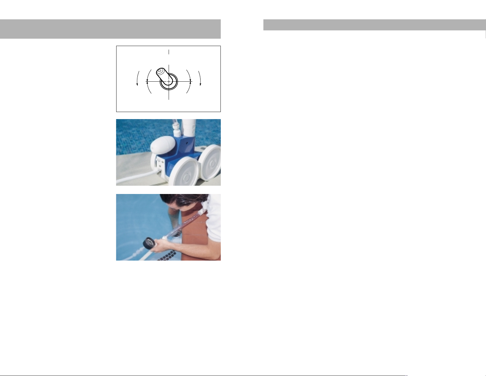
A.
Thrust Jet: Acts as a steer-
ing mechanism; the recommended setting is 11 o’clock.
Moving the thrust jet to the
left will turn the cleaner left
and vice versa. Setting the
thrust jet between 11:00 and
1:00 will provide maximum
climbing ability.
B.
Sweep Hose Adjustment
Screw: Regulates water flow
to the sweep hose; the recommended setting is adjusted
to provide a gentle sweeping
motion. The sweep hose
removes debris from corners
and steps. Tightening the
screw decreases the sweeping
motion and vice versa.
C.
Head Float: Affects the ballast
of the cleaner; the recommended setting is all the way
forward. Moving the head float
forward (toward the cleaner)
improves climbing ability and
vice versa.
D.
Wheel RPM: The pressure
relief valve is designed to automatically regulate the pressure to the cleaner. For proper operation the
cleaner should run between 28-32 RPM. (For the 380, the water pressure should not exceed the wheel RPM by more than 2 psi; for the 360,
the water pressure should be between 12-14 psi.)
For 380: The RPM can be reduced by replacing the blue UWF restrictor
with the red UWF restrictor. If needed, the RPM can be reduced further by
unscrewing the pressure relief valve.
10
C
A
B
D
N
U
11
S
E
H
S
U
P
93
D
E
P
U
T
S
F
E
L
T
I
E
R
C
N
I
C
R
E
H
E
S
U
12
S
E
S
A
A
S
E
6
N
I
C
S
T
L
C
R
I
M
I
B
G
I
N
H
G
T
G
N
I
B
M
I
L
Page 11

4. Is the hose floating
properly? For 380: The white hoses (hose sections closest to
the pool wall) should float at the surface of the
pool with no dips or sags in the hose. The soft
clear hose (first section closest to the cleaner)
should angle down to the Polaris with no dips
or sags. If the hoses do not float properly,
check the float placement:
• There should be one float against the in-line
back-up valve on the side opposite the
cleaner and another float within 2-3 feet.
• Floats on the white hoses should be no less
than 1-1/2 feet and no more than 3 feet apart,
so that the white hoses do not sag.
• It may be necessary to remove floats to
maintain proper spacing.
If the float placement is correct and the hoses
still do not float properly, replace the floats.
For 360: • There should be one float on the back-up
valve, one float 4 feet back and one float
7 feet back from the back-up valve.
`•The hose should angle down to the
Polaris with no dips or sags.
If the float placement is correct and the
hoses still do not float properly, replace
the floats.
13
3. Is the back-up valve Watch the back-up jet. The jet should cycle on
cycling? and off. The jet should stay off longer than
it stays on. If it does not cycle properly, bring
the cleaner and hose in for repair.
With the Cleaner Off:
Topic Recommendation
1. Verify the recommended • Thrust jet set at 11 o’clock position.
settings: • Head float pushed all the way forward.
• Sweep hose adjusted for a gentle sweeping
motion when the cleaner is running.
2. Is the drive train Spin each wheel independently. As you spin
functioning? each wheel, all the wheels should spin togeth-
er freely. If not, bring the cleaner in for repair.
3. Is the hose cut properly?
For 380: • The soft clear hose (first section closest to
the cleaner) should be equal to the greatest depth of the pool. (After a period of
time in the water, the clear hose will begin
to turn white.)
• The hard white hose sections should be
equal in length.
• The end of the feed hose should reach within
6 inches of the farthest point of the pool.
For 360: • The end of the hose should reach within
6 inches of the farthest point with the pool
pump on.
12
Page 12

For 360:
Verify there is one float pushed as close to the back-up valve as possible
on the side opposite the cleaner and two additional floats installed one
4 inches upstream and one 7 feet upstream from the back-up valve.
4. Always review hose cutting with the customer. For complete hose cutting
procedures, refer to page 3, or the installation section of the cleaner’s
owner’s manual.
Wet Function Bench Test
For 380: Disconnect the clear hose from the white feed hose and connect the
clear hose, using the swivel, directly to the end of the Wet Function Bench
Test hose. (If you don’t have the clear hose, attach the Wet Function Bench
Test hose directly to the Polaris head.) Attach the other end of the clear hose
to the Polaris head, and then thread the inlet fitting to the water source.
For 360:
Attach the feed hose to the Polaris. Disconnect the quick disconnect from the hose and attach the inlet fitting. If the feed hose is unavailable,
attach the inlet fitting to the bench test hose provided and attach the bench
test directly to the Polaris. Attach the inlet fitting to the water source.
Set the Polaris on a brick or piece of wood (2 inches x 4 inches) or something
similar to allow the wheels to spin freely. Remove the bag. Place a coping
brick or deck-o-seal can over the vacuum tube to cover the vac jets. Secure
the sweep hose and turn on the water. Adjust water volume to activate
the wheels.
1. Verify that all the wheels are rotating. If not:
• Check for a clogged drive jet.
• Check for a broken wheel axle or stripped single-side wheel.
• Check for a broken or damaged drive belt or stripped transfer pulley.
• Check for a pebble binding the drive train gears.
2. Verify that there is water flow through the sweep hose and thrust jet.
If not:
• Check the water management system for leaks.
• Check the water management system hoses and hose clamps.
3. Carefully lift the brick on top of the vacuum tube and verify that there are
three even, distinct jets in the vacuum tube. It may be easiest to
check this with the cleaner flipped upside down. If all distinct jets are
not present:
• Check the water management system hose clamps.
• Clear the vacuum jets which are obstructed.
• If additional spray is present, check the water management system for
leaks or loose hose clamps.
15
V. TR OUBL ES HOO TI NG ON THE B ENC H
Quite often retail dealers and service centers are faced with a Polaris which is
brought into the bench (retail store or service department) with no detailed
operational information other than “it isn’t working”or “it stays on the steps.”
This does not give the technician much in the way of direction for troubleshooting the cleaner. Often the technician identifies and fixes an obvious
problem without looking further for other less visible problems within the
cleaner. When these less visible problems are not caught on the first trip to
the bench, and return trips are required, or when the cleaner’s operation is
compromised due to incomplete service, the customer can lose confidence in
both the dealer and the product. The following tips will help in troubleshooting
the Polaris 380/360 and will allow you to solve your customers’ problems correctly the first time.
The Wet Function Bench Test Kit (380 part #G-10; 360 part #9-100-6005)
removes the guesswork from bench repairs. This kit allows you to connect
the Polaris to a water source (i.e. garden hose or water faucet) at your bench
facility and test all of the operational functions of the cleaner head and backup valve. The Wet Function Bench Test can be used both inside a store with
a test tank facility or a deep sink, or outside of the store. High pressure water
streams will be emitting from various orifices of the Polaris during the testing,
so be sure to choose a work area that will not be damaged by water.
The Testing Begins
Have the customer bring both the cleaner head and the feed hose into
the bench.
Visual Inspection
Start by doing a visual inspection, checking the following:
1. Verify the filter screen is clean.
2. Verify the swivels turn smoothly and the arrows are pointing toward the
cleaner head.
3. Verify the hose cutting.
For 380:
Verify hose floats are evenly spaced on the white hoses and both the
white hoses are the same length. Verify the clear hose is cut to the depth
of the pool. For the 380 clear hose, verify there is one float against the
back-up valve on the side opposite the cleaner and another float within
2-3 feet. For the 280/180 clear hose, verify there is one float on either
side of the back-up valve and another float within 2-3 feet.
14
Page 13

VI. TROUBLESHOOTING
PROCEDURES POOLSIDE
380 Poolside Procedures
Polaris strongly recommends always following these troubleshooting
procedures. By using these procedures, most problems will be identified within minutes. If you have any questions, please call 1-800-VAC-SWEEP.
With the Cleaner On:
Steps Recommendation
1. Check water pressure using It should be between 28-32 psi. Refer
the Pressure Tester (part #G-35): to page 25.
2. Check the wheel RPM: It should be between 28 and 32.
(Remember to hold the cleaner under
water when counting the wheel RPM.)
Refer to page 26.
The psi should not exceed RPM by
more than 2 psi.
3. Check that all jets are Turn the cleaner upside down. The
flowing unobstructed: three vacuum jets should have even,
unobstructed flow. Check the thrust
jet and sweep hose orifice. Refer to
page 29.
4. Check that the back-up valve The back-up jet cycles on and off.
is cycling properly: It should stay off longer than it stays on.
With the Cleaner Off:
Steps Recommendation
1. Check the feed hose length: • Clear hose length equal to greatest
depth of pool.
• Hard white hoses equal in length.
• Entire feed hose reaches within 6
inches of farthest point of pool.
• Floats on the white hoses spaced
evenly, 1-1/2 to 3 feet apart.
17
4. Verify that back-up valve is working correctly:
For the in-line back-up valve part #G-52 (380 serial #335727 or
higher) and part #9-100-1200 (360 serial #537791 or higher):
• Verify the in-line back-up valve is cycling.
• If not, open the valve and remove the mechanism.
• Separate the mechanism and inspect the turbine for debris.
• Flush or clear debris as necessary.
For the in-line back-up valve part #G-41 (380 serial #225071-335726)
and in-head timer assembly part #9-100-7006 (380 serial #K225070
or lower) and in-head timer assembly part #9-100-1003 (360 serial
#537790 or lower):
• Verify the valve/timer is cycling.
• If not, open the valve/timer and check the turbine jet for debris (380 jet
is red, 360 jet is white).
• If the jet is clear, replace the timer assembly or mechanism with in-line
back-up using an In-line Back-up Kit (380 part #9-100-9040; 360 part
#9-100-3200). Refer to Section H, Converting an In-head Timer to an
In-line Back-up Valve on page 31.
Even if the cleaner passes all of the Wet Function Bench Tests, it is always
a good idea to remove the tops and to do a visual inspection of the moving
parts, along with the water management system hoses and o-rings inside
the cleaner.
Once you have made any necessary repairs, run through the wet test one
more time. Verify all the functions are operating and that the basic factory
head adjustments are made to the thrust jet and head float. Then, with a
piece of black tape, mark a single-side wheel and remind the customer that
when reinstalled in the pool, the taped wheel should rotate at 28-32 RPM for
the 380/360.
Remember, being able to diagnose the problem the first time will build your
customer’s confidence in both you and the Polaris product. If you have any
question or would like to receive a free Wet Function Bench Test (Part #G110 for the 380 or part #9-100-6005 for the 360), please call our Technical
Support Department at 1-800-VAC-SWEEP.
16
Page 14

5. Check the feed hose length • Cleaner should pull all loops from hose
and flotation: when it reaches farthest point of pool.
• Position one hose float against the
back-up valve on side opposite
of cleaner.
• Position one float 4 feet away and
one float 7 feet away from the
back-up valve.
With the Cleaner Off:
Steps Recommendation
1. Check the drive train: Spin one of the wheels; all wheels
should spin freely together.
2. Check the head float: If there’s any water in it, replace it.
3. Check the head adjustments: • Head float all the way forward.
• Thrust jet set at 11:00 position.
• Sweep hose adjusted for gentle
sweeping motion when the cleaner
is running.
19
2. Check the drive train: Spin one of the wheels; all wheels
should spin freely together. Refer to
page 33.
3. Check the head float: If there’s any water in it, replace it.
4. Check the head adjustments: • Head float all the way forward.
• Thrust jet set at 11:00 position.
• Sweep hose adjusted for gentle
sweeping motion when the cleaner
is running.
• Bag should be clear of debris.
Refer to page 10.
5. Check that hose floats properly: If the hose does not float properly,
check the float placement. Refer to # 4
on page 13.
360 Poolside Procedures
Polaris strongly recommends always following these troubleshooting
procedures. By using these procedures, most problems will be identified within minutes. If you have any questions, please call 1-800-VAC-SWEEP.
Note: The 360 Cleaner requires 1 HP pump.
With the Cleaner On:
Steps Recommendation
1. Check water pressure using It should be between 12-14 psi.
a pressure stick:
2. Check the wheel RPM: It should be between 28 and 32.
(Remember to hold the cleaner under
water when counting the wheel RPM.)
3. Check that all jets are Turn the cleaner upside down. The
flowing unobstructed: three vacuum jets should have even,
unobstructed flow. Thrust jet and
sweep hose should be active.
4. Check that the back-up valve The back-up jet cycles on and off.
is cycling properly: It should stay off longer than it stays on.
18
Page 15

21
5. Verify that the base weight is installed.
6. Check the feed hose for excessive swelling or leaks.
7. Install a Street Ell at the wall (part #9-100-9003).
PROBLEM: Thrust jet and/or sweep hose sprays out of the pool when
the cleaner is hung up on a step or the UWF.
SOLUTION:
1. Verify proper water pressure
and wheel RPM (380–28-32
psi; 360–12-14 psi;
380/360–28-32 RPM). (Refer
to pages 25-26.)
2. Verify the hose is cut correctly.
(380 refer to page 3; 360 refer
to page 7.)
3. Check that the pool water level
is not too high.
4. Trim 7 inches off the sweep
hose (at the end that attaches
to the Polaris) and add a Sweep
Hose Weight (part #B-2).
5. If the cleaner hangs up on the
Universal Wall Fitting, install a
Street Ell at the wall (part #9100-9003).
PROBLEM: Cleaner moves too slowly.
SOLUTION:
1. Check the filter screen in the quick disconnect for debris.
2. Verify proper water pressure and wheel RPM (380–28-32 psi; 3
60–12-14
psi
; 380/360–28-32 RPM). (Refer to pages 25-26.)
3. Check for leaks in hoses, connections and swivels.
4. Check the back-up valve for proper operation. (Refer to pages 30-31.)
5. Check for holes in the sweep hose.
6. Check for debris in the drive jet. (Refer to page 29.)
7. Check the drive train. (Refer to page 33.)
8. Check the water management system hoses for leaks and loose
hose clamps.
VII. PROBLEM/SOLUTION TROUBLESHOOTING
For best results follow the problem/solution troubleshooting scenarios in the
order in which they are listed. If you have any questions, please call 1-800VAC-SWEEP.
PROBLEM: Cleaner hangs up on corners, steps or other obstacles
longer than two back-up cycles.
SOLUTION:
1. Verify proper water pressure
and wheel RPM (380–28-32
psi; 360–12-14 psi;
380/360–28-32 RPM). (Refer to
pages 25-26.)
2. Verify the in-line back-up valve
is cycling. (Refer to pages
30-31.)
3. Check for debris in bag.
4. Verify the floats are floating and spaced properly. (Refer to #4 on page 13.)
5. Adjust the thrust jet to prevent the cleaner from hanging up. (Note: verify
that the new setting does not cause the cleaner to circle or hinder its
wall climbing.)
6. Move the head float back to decrease the cleaner’s ability to climb into
areas where it may hang up.
7. Move the back-up valve and its adjacent float further back on the hose
(away from the cleaner).
8. Install a Ladder Guard Kit (part #G-21) where applicable.
PROBLEM: Feed hose tangles or ties itself in knots.
SOLUTION:
1. Verify the hose is cut correctly.
(380 refer to page 3; 360 refer
to page 7.)
2. Verify proper water pressure
and wheel RPM (380–28-32
psi; 360–12-14 psi;
380/360–28-32 RPM). (Refer to
pages 25-26.)
3. Verify the floats are floating
and spaced properly. (Refer to #4 on page 13.)
4. Verify the swivels turn freely and the flow arrows point toward the cleaner.
20
Page 16
23
PROBLEM: Cleaner runs in circles; it does not cover the entire pool.
SOLUTION:
1. Verify the cleaner is adjusted to the recommended settings. (Refer to
page 10.)
2. Verify proper water pressure and wheel RPM (380–28-32 psi; 360–12-14
psi; 380/360–28-32 RPM). (Refer to pages 25-26.)
3. Check the drive train. (Refer to page 33.)
4. If the first section of hose at the cleaner has a curve to it, verify that the
curve is aligned with the curve of the feed pipe.
5. Verify proper hose cutting and float placement. (380 refer to page 3; 360
refer to page 7.)
6. Adjust the thrust jet to make the cleaner run in more of a straight direction. (Refer to page 9.)
7. If the cleaner has an in-line back-up valve, verify that there is either a
timer blank and base weight, or a disabled in-head timer installed. (Refer
to page 30.)
8. If the cleaner is installed in a vinyl or fiberglass pool, install Kraton®Tires
(part #C-12).
9. If the pool is deep, position thrust jet down to help drive the cleaner out of
the hopper.
10. Check axle block alignment.
PROBLEM: Cleaner spends too much time on the pool walls; it does not
cover the pool floor.
SOLUTION:
1. Verify proper water pressure and wheel RPM (380–28-32 psi; 360–12-14
psi; 380/360–28-32 RPM). (Refer to pages 25-26.)
2. Verify that the base weight is installed.
3. Adjust the head float or thrust jet to reduce climbing ability.
PROBLEM: Cleaner will not stay on pool bottom; it floats around the pool.
SOLUTION:
1. Verify proper water pressure and wheel RPM (380–28-32 psi; 360–12-14
psi; 380/360–28-32 RPM). (Refer to pages 25-26.)
2. Verify the back-up valve is cycling. (Refer to page 30-31.)
3. Check the vacuum jets. (Refer to page 29.)
4. Check for proper float placement. (Refer to #4 on page 13.)
5. Verify that the base weight is installed.
6. Look for air entry from the filtration system.
7. Replace the bag if it is full of algae.
22
PROBLEM: Cleaner will not climb walls.
SOLUTION:
1. Check the filter screen in the quick disconnect for debris.
2. Verify proper water pressure and wheel RPM (380–28-32 psi; 360–12-14
psi; 380/360–28-32 RPM). (Refer to pages
25-26.)
3. Position the thrust jet between 11:00 and 1:00 for maximum
climbing ability.
4. Verify the head float is positioned all the way forward.
5. Check the drive train. (Refer to page 33.)
6. Check for debris in the vacuum jets. (Refer to page 29.)
7. Install Kraton®Tires (part #C-12).
PROBLEM: Sweep hose sprays too much water.
SOLUTION:
1. Verify there is a Sweep Hose
Scrubber (part #9-100-3105)
installed.
2. Screw in the sweep hose
adjustment screw to
decrease the sweep
hose action.
3. Trim 7 inches off the sweep
hose (at the end that attaches
to the Polaris) and add a
Sweep Hose Weight (part #B-2).
4. Adjust the head float or thrust jet to reduce climbing ability.
PROBLEM: Sweep hose is sucked into the vacuum tube.
SOLUTION:
1. Verify the sweep hose orifice
is not blocked by the sweep
hose scrubber.
2. If the sweep hose is whipping
wildly or there is no movement
at all, adjust the sweep hose
adjustment screw until the
sweep hose has a gentle
sweeping motion.
3. Trim 7 inches off the sweep
hose (at the end that attaches to the Polaris).
Page 17

VIII. HOW TO CHECK AND SERVICE
A. Pressure
For 380: When checking water pressure, you should also check wheel RPM
(see Section B on page 26). Water pressure should not exceed 32 psi and
wheel RPM should not be lower than 28. Also, water pressure should not
exceed wheel RPM by more than 2 psi.
For 360: Water pressure should be between 12-14 psi, and wheel RPM
between 28-32.
CHECK:
1. Attach the pressure stick to the
end of the feed hose.
2. Turn on the filtration pump and
then the booster pump.
3. Hold the end of the pressure
stick under the water.
4. The pressure should be
between 28-32 psi for the 380
and between 12-14 psi for
the 360.
Note: Use a 0 - 60 psi gauge for
the 380, and a 0 - 30 psi gauge
for the 360.
SERVICE:
If the pressure is too high:
For 380:
1. Install a blue UWF
Restrictor (part #10-108-00)
if one is not already installed.
2. Replace the blue UWF restrictor with the red UWF restrictor.
3. Unscrew the pressure relief
valve until the pressure is 2832 psi.
For 360:
1. If there is a dedicated line,
adjust the valve until proper
psi is achieved.
2. For after market installations,
2524
PROBLEM: Cleaner runs on its side.
SOLUTION:
1. Verify the bag is empty.
2. Check the head float. If it has
water in it, replace it.
3. Verify the hose floats are floating and spaced properly.
(Refer to #4 on page 5.)
4. Check the feed hose for leaks.
5. Check the vacuum jets. (Refer
to page 29.)
Page 18

under the water and count
the wheel revolutions for
one minute.
4. Wheel RPM should be 28-32.
SERVICE:
If the pressure is more than
32 RPM:
For 380:
1. Install a blue UWF Restrictor
(part #10-108-00) if one is not already installed.
2. Replace the blue UWF restrictor with the red UWF restrictor.
3. Unscrew the pressure relief valve until the proper RPM is reached.
For 360:
1. For dedicated cleaner line, adjust the pressure relief valve.
2. For after market installations, open up the holes on the return jets
until desired wheel RPM is achieved.
If the pressure is less than 28 RPM:
For 380:
1. Remove the UWF restrictor if one is installed.
2. Verify there is adequate water pressure (28-32 psi). (Refer to page 25.)
3. Check the drive train. (Refer to page 33.)
4. Check the drive jet. (Refer to page 29.)
5. Check the o-ring between the feed pipe/timer blank assembly and
the
water management system.
6. Check the water management system hoses for leaks and loose
hose clamps.
For 360:
1. For dedicated cleaner line, adjust the cleaner line valve.
2. Back wash or clean the filter.
3. Clean skimmer and pump baskets.
4. Clean filter screen.
5. Check for excessively leaking swivels.
6.
Install smaller eyeballs in return lines (Eyeball Regulator,
part #10-107-
00).
2726
open up a return line. If that doesn’t work, make the holes in the
adjustable eyeball larger.
If the pressure is too low:
For 380:
1. Check the filter screen for debris.
2. Make sure the pressure relief valve is screwed in completely. If it is and
water is being released, replace the pressure relief valve.
3. Remove the UWF restrictor if one is installed.
4. Check hose and swivels for leaks.
5. Completely open the gate valve on the booster pump if there is one.
6. Make sure the skimmer basket and pump basket are
clean.
7. Check the pump hose washers
for swelling (old style black hoses), see
picture on page 25.
8. Remove the pressure restrictor in the pump if one is installed.
9. Verify the pump installation is correct. (Refer to page 31.)
10. Check for kinked or collapsed booster pump hoses.
11. If there is an over-the-deck installation, make sure the feed hose is at
least 3/4 inch in diameter.
For 360:
1. Check the filter screen for debris.
2. Make sure the pressure relief valve is screwed in completely. If it is
and water is being released, replace the pressure relief valve.
3. Remove the UWF restrictor if one is installed.
4. Check hose and swivels for leaks.
5. Make sure the skimmer basket and pump basket are
clean.
B. Wheel RPM
For 380: When checking wheel RPM, you should also check water pressure
(see Section A on the previous page). Water pressure should not exceed 32
psi and wheel RPM should not be lower than 28. Also, water pressure should
not exceed wheel RPM by more than 2 psi.
For 360: Water pressure should be between 12-14 psi, and wheel RPM
between 28-32.
CHECK:
1. Mark the single-side wheel.
2. Turn on the filtration and
booster pumps, and allow the
back-up valve to complete a
back-up cycle.
3. Hold the cleaner completely
Page 19

D. Jets
CHECK:
1. Turn the cleaner upside down.
The three vacuum jets should
have even, unobstructed flow.
2. Additional spray around the
vacuum jets indicates cracks. If
cracks are present, replace the
water management system.
(Refer to page 38.)
3. The thrust jet and sweep hose
jet should have even, unobstructed flow.
If you find one
clogged jet, all jets should
be checked for debris
including the drive jet. (Refer
to page 18.)
SERVICE:
If the single jet is obstructed:
1.
Tear down the cleaner to
the water management
system. (Refer to page 38.)
2. Lift out the front jet and cut the hose clamp.
3. Remove the jet and clear it with a paper clip. Make sure you remove the
debris completely.
If the double jets are obstructed:
1. Clear the jets while in place with a paper clip.
2. Run water through the jets to flush the debris out the water management
system inlet.
E. Drive Jet
CHECK:
1. Remove the drive train. (Refer to
DRIVE TRAIN REMOVAL AND
REPLACEMENT disassembly
steps on page 35.)
2. Reinstall the feed pipe/timer
blank assembly and feed hose.
3. Verify that the drive jet is clear. If
you find a clogged jet, all jets
should be checked for debris.
29
C. Water Flow Diagram
The following tests can be performed poolside or at a service
center with the use of a Wet
Function Bench Test Kit
(380: part #G-110; 360: part
#9-100-6005).
28
Page 20

31
SERVICE:
1. If the drive jet is obstructed with
debris, remove the feed
pipe/timer blank assembly.
Clear the jet with a paper clip.
After clearing the jet, run water
through the jet to flush the
debris out the water management system inlet.
2. Reinstall the feed pipe/timer blank assembly and retest.
3. Remove the feed pipe/timer blank assembly and reassemble the cleaner.
(Refer to DRIVE TRAIN REMOVAL AND REPLACEMENT reassembly
steps on page 35.)
F. I n -l in e B ac k- up Va l ve s
380 - Part #G-52; 360 - Part #9-100-1200
(For 380 cleaners with serial #337487 or higher and 360 cleaners with serial
#537710 or higher)
CHECK:
The back-up jet should cycle on
and off. It should stay off longer
than it stays on. There should be
no spray from around the back-up
jet. If so, check the housing for
cracks or a damaged o-ring.
SERVICE:
If the back-up valve does not cycle
properly, check the mech
anism
for debris:
1. Unscrew the back-up valve
collar and pull apart the backup valve cases.
2. Remove the mechanism.
3. Depress the tabs on the
sides of the mechanism and
separate the mechanism.
4. Inspect the turbine for debris
and flush or clear debris
as necessary.
30
5. Reassemble the mechanism making sure the valve seat is in place.
6. Replace the mechanism in the case making sure the back-up jet sits in
the jet opening at the bottom of the case.
7. Reattach the valve to the feed hose making sure the flow arrows point
toward the cleaner.
380 - Part #G-41
(For 380 cleaners with serial #225071 - 337486)
CHECK:
The back-up jet should cycle on
and off. It should stay off longer
than it stays on.
SERVICE:
If the back-up valve does not cycle
properly, check the turbine jet
for debris:
1. Remove the back-up
valve case.
2. Disconnect the mechanism
from the feed hose.
3. Remove the top housing,
teflon washer and
turbine wheel.
4. Visually check the red jet for
debris and clear it with a paper
clip. Do not allow the debris
to fall into the back-up valve.
If the jet was clogged, all
jets should be checked
for debris.
5. Reassemble the mechanism. If no debris was present, replace the
Mechanism (part #E-60) and reassemble the back-up valve.
G. In-head Back-up Timer
(For 380 cleaners with serial numbers prior to 225071, and 360
cleaners with serial numbers prior to 537710 which have not
been converted previously to an in-line back-up valve)
CHECK:
1. Turn the cleaner upside down.
2. The back-up jet should cycle on and off. It should stay off longer than it
stays on.
Page 21

SERVICE:
If the back-up timer does not cycle
properly, check the turbine jet
for debris:
1. Remove the drive train. (Refer
to DRIVE TRAIN REMOVAL
AND REPLACEMENT disassembly steps on page 35.)
2. Remove the in-head timer.
3. Remove the two screws on the
top of the timer.
4. Remove the top housing, teflon
washer and turbine wheel.
5. Visually check the red jet for
debris and clear it with a paper
clip. Do not allow the debris
to fall into the back-up timer.
If the jet was clogged, all
jets should be checked
for debris.
6. Reassemble the timer. If no debris was present, replace the timer (part
#9-100-7006) and reassemble the cleaner. (Refer to DRIVE TRAIN
REMOVAL AND REPLACEMENT reassembly steps on page 35.)
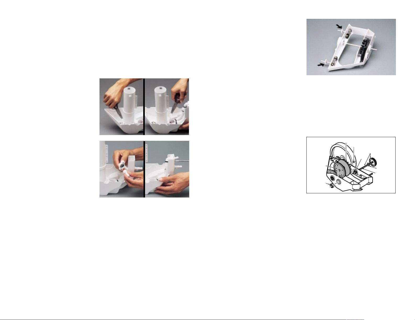
H. Converting an In-head Timer to an In-line Back-
up Valve
(Using In-line Back-up Valve Conversion Kit #9-100-9040 for the 380,
and #9-100-3200 for the 360)
1. Disconnect the cleaner and
remove the bag, head float,
tops, feed pipe, drive train
and in-head timer. Discard
the back-up timer and old
feed pipe.
2. If the frame has not already
been notched, file the frame to
provide proper clearance for
the feed pipe/timer
blank assembly.
3332
3. If the jet retainers are the old
style shown at left, remove
them by breaking the glue joint
with a flat-blade screwdriver. If
they are the new style jet
retainers, skip to step 5.
4. Hold the water management
system in place and snap in
the new jet retainers.
5. Place the new base weight
on the rear jet retainer with
the weight flush against the
vac tube.
6. Reinstall the frame onto the
base of the cleaner and reinstall the four screws, leaving
them loose.
7. Place the o-ring onto the new
feed pipe/timer blank assembly and install the feed pipe
being careful not to pinch
the o-ring.
8. Tighten the four screws into
the frame and reassemble
the cleaner.
I. Drive Train
CHECK:
1. Spin each wheel. All wheels
should turn freely and together.
2. Check for binding and debris in
the gears, frame and bearings.
SERVICE:
1. If the front double-side wheel
turns independently or skips,
check for a broken wheel axle
(A: part #9-100-1008), or broken or stripped drive belts (B: part #9-100-1017).
2. If the front double-side wheel turns independently or skips, check for a
stripped transfer pulley (C: part #9-100-1007) and/or a stripped single-side
wheel (D: part #9-100-1116), or a stripped drive gear (part #9-100-1132).
B
C
D
A
Frame
2"
File Here
Old Style
New Style
Vac Tube
Base
Weight
Rear Jet Retainer
Page 22

J. Hose Length
To service the feed hose, refer to “Hose Cutting” in Section II (380 refer to
page 3; 360 refer to page 7.)
IX. PART REMOVAL AND REPLACEMENT
A. Single-side Wheel
DISASSEMBLY:
1. Remove the head float.
2. Remove the tops (screw is on the double-wheel side).
3. Remove the hub cap.
4. Remove the e-clip.
5. Remove the wheel.
6. Remove the tire from the wheel.
REASSEMBLY:
1. Install the tire on the new wheel.
2. Support the transfer pulley shaft and install the new wheel by pushing it
down onto the shaft until the e-clip groove is flush with the wheel.
3. Replace the e-clip.
4. Replace the hub cap.
5. Replace the tops:
• Install the top for the doublewheel side; make sure the
tabs are inside the base.
• Install the top for the singlewheel side; make sure the
tabs are inside the base.
Push down on the top until it
snaps into place.
• Install the screw from the double-wheel side.
6. Replace the head float to the recommended setting.
B. Drive Train Removal and Replacement
The following DRIVE TRAIN REPAIR AND REPLACEMENT steps must be
followed for Sections C through H below. Note: Whenever possible, check
the bearings and replace them if they do not spin freely.
DISASSEMBLY:
1. Remove the head float.
2. Remove the tops (screw is on
the double-wheel side).
3. Remove the feed pipe/timer
blank assembly (3 screws).
4. Loosen the four frame screws.
5. Lift up at the rear of the frame
and pull straight up.
3534
Floats Are Evenly Distributed
(1-1/2 to 3 Feet Apart)
Universal Wall
Fitting
Properly Sized Feed Hose
2-3 Feet Apart
White Hoses Are Cut to Equal Lengths
Clear Hose is Equal to
Greatest Depth of Pool
Entire Feed Hose Reaches Within 6" of Farthest Point of Pool
Feed hose is cut correctly if:
A. Clear hose is equal to greatest depth of pool.
B. Hard white hoses are equal in length.
C. Entire feed hose reaches within 6” of farthest point of pool.
D. Floats on white hoses are spaced evenly, between 1-1/2 to 3 feet apart.
Universal Wall
Fitting
Entire Feed Hose Reaches Within 6" of Farthest Point of Pool*
Cut excess hose from
first section of hose
7'
Float
Float
Float
4'
Measure with pool
pump on and pressure
tester underwater
Pressure Tester
Properly Sized Feed Hose for 360
Properly Sized Feed
Hose for 380
Page 23

REASSEMBLY:
1. Install the drive train, dropping
it in nose first. Lift the base up
to the frame and tighten the
four frame screws.
2. Install the feed pipe/timer
blank assembly (3 screws).
Make sure the o-ring has not
pushed out.
3. Replace the tops:
• Install the double-wheel side
top; make sure the tabs are
inside the base.
• Install the single-wheel
side top; make sure the
tabs are inside the base.
Push down on the top until
it snaps into place.
• Install the screw from the
double-wheel side.
4. Replace the head float to the recommended setting.
C. Double-side Wheels
DISASSEMBLY:
1. Follow DRIVE TRAIN
REMOVAL AND REPLACEMENT disassembly steps.
2. Disengage the drive belt.
3. Remove the wheel (note the
direction of the bearing shield if
applicable):
• Remove the hub cap.
• Remove the e-clip.
• Remove the wheel.
• Remove the belt.
4. Remove and check the two bearings.
5. Remove the tire from the wheel.
REASSEMBLY:
1. Install the tire, two bearings (shielded side out) and belt onto the new wheel.
2. Verify that the bearing shield is positioned correctly and install the new
wheel onto the shaft.
3. Install the e-clip and hub cap.
4. Engage the drive belt. Belts should have about 1/4 inch deflection. If they
are excessively loose, refer to the tension adjustment section on page 37.
5. Follow DRIVE TRAIN REMOVAL AND REPLACEMENT reassembly steps.
D. Drive Belts
DISASSEMBLY:
1. Follow DRIVE TRAIN
REMOVAL AND REPLACEMENT disassembly steps.
2. Disengage both drive belts.
3. Remove both wheels from the
double-wheel side (note the
direction of the bearing shields
if applicable):
• Remove the hub caps.
• Remove the e-clips.
• Remove the wheels.
• Remove the belts.
REASSEMBLY:
1. Verify that the bearing shields are positioned correctly.
2. Place the new large belt on the front wheel and the new small belt on the
back wheel, and install the wheels, e-clips and hub caps.
3. Engage the rear belt inside the belt divider on the transfer pulley and then
onto the rear wheel.
4. Engage the front belt outside the belt divider on the transfer pulley and
then onto the front wheel.
5. Follow the tension adjustment steps below.
6. Follow DRIVE TRAIN REMOVAL AND REPLACEMENT
reassembly steps.
TENSION ADJUSTMENT:
The drive belts should have approximately 1/4 inch deflection. If the belts
seem excessively loose:
1. Loosen the axle block screws.
2. To align the wheels, lay the cleaner down flat on the double-side wheels.
3. Move the axle block until the belt has 1/4 inch deflection. (Very tight or
very loose belts could adversely affect cleaner performance.)
4. Tighten the axle block screws.
5. Spin the double-side wheels and recheck the drive belt deflection.
3736
Page 24
E. Water Management System
DISASSEMBLY:
1. Follow DRIVE TRAIN REMOVAL AND REPLACEMENT
disassembly steps.
2. Remove the base weight.
3. Remove the lower turbine housing.
4. Remove the sweep hose adjustment screw.
5. Remove the thrust jet and o-ring, and the sweep hose barb (4 screws).
6. Remove the jet retainers by
popping them out with needlenose pliers.
7. Remove the water management system.
REASSEMBLY:
1. Install the new water management system.
2. Install the sweep hose barb
with the keyway aligned, and
insert it through the lower hole
in the base (2 screws).
3. Install the jet retainers.
4. Install the o-ring and thrust jet
through the top hole in the
base, and adjust the thrust jet to
11 o’clock position.
5. Install the two thrust jet screws
(be careful not to overtighten).
6. Install the sweep hose adjustment screw.
7. Replace the lower turbine housing and base weight.
8. Follow DRIVE TRAIN REMOVAL AND REPLACEMENT
reassembly steps.
F. F r am e Ex c ha ng e
DISASSEMBLY:
1. Follow DRIVE TRAIN REMOVAL AND REPLACEMENT
disassembly steps.
2. Remove the wheels:
• Remove the hub caps.
• Remove the e-clips.
• Remove the belts.
• Remove the wheels.
3. Remove the bearing shields
from the double-wheel side.
4. Remove the upper
turbine housing.
5. Call Polaris at 1-800-VACSWEEP for a return goods
authorization number and
frame exchange procedures.
G. Transfer Pulley/Drive Shaft Assembly
DISASSEMBLY:
1. Follow DRIVE TRAIN REMOVAL AND REPLACEMENT
disassembly steps.
2. Remove the upper turbine housing.
3. Disengage both drive belts from the transfer pulley.
4. Remove the rear double-side wheel and the single-side wheel:
• Remove the hub caps.
• Remove the e-clips.
• Remove the wheels.
• Remove the belt (double-
side wheel only).
5. Remove the transfer
pulley/drive shaft assembly:
• Remove e-clip #1.
• Pull out the transfer
pulley/drive shaft assembly.
• Push out bearing #2.
REASSEMBLY:
1. Install the bearing shield onto the new shaft.
2. Install the shaft through bearing #1.
3. Install the e-clip near the middle of the shaft.
4. Insert the shaft through the turbine wheel, drive gear and frame. Lift
the end of the shaft and push until the e-clip is flush against the bearing.
5. Install bearing #2 shielded side out.
6. Place the belt on the double-side wheel and install the wheel, e-clip and
hub cap.
7. Engage the rear belt inside the belt divider on the transfer pulley and then
onto the rear wheel.
8. Engage the front belt outside the belt divider on the transfer pulley and
then onto the front wheel.
9. Install the single-side wheel, e-clip and hub cap.
3938
Drive Gear
(side with
shortest
hub)
Bearing #2
(Shield
side out)
Turbine Wheel
E-clip #1
Bearing
#1
Transfer Pulley/
Drive Shaft
Assembly
Bearing
Shield
Notched
Area
for E-clip
Page 25

10. Install the upper turbine housing.
11. Follow DRIVE TRAIN REMOVAL AND REPLACEMENT
reassembly steps.
H. Gear Kit
Here are basic steps for replacing the gear kit. More explicit instructions
are contained with the gear kit.
DISASSEMBLY:
1. Follow steps 1-5 of Section F on page 39.
2. Remove the turbine wheel and drive gear.
3. Remove the compound gear.
REASSEMBLY:
1. Install the new compound gear.
2. Replace the turbine wheel and drive gear.
X. POLARIS BOOSTER PUMP FOR POLARIS 380
A. Exploded Parts Diagram
R
O
T
A
T
I
O
N
PUMP
SUPPLY
PUMP
DISCHARGE
13
1
3
5
6
2
8
9
10
12
11
9
14
4
7
Index Part Number Quantity Description
1P-5 1Volute
2P-15 1Impeller
3P-55 1Seal, Stainless Steel Cup and Spring
4P-95 1O-ring, Bracket
5P-10 1Bracket
6P-35 2Bolt, Stainless, Bracket to Motor
7P-40 1O-ring for Shaft
8P-61 1Motor, 3/4" HP, Threaded Shaft
9P-25 6Bolt/Nut, Stainless, Volute to Bracket
10 P-80 1 Rubber Strip, Motor and Bracket
11 P-70 1 Pump Stand with Feet, Strip
12 P-75 4 Rubber Feet
13 P-65 2 Bolt, Stainless, Stand to Bracket and Motor
14 P-20 1 1/8" NPTM Plug, Plastic
PLEASE NOTE: All of the parts fit the PB3 Booster Pump produced in 1978 except P-20
and P-25. Call 1-800-VAC-SWEEP for more information on the Polaris Booster Pump.
4140
Frame
Turbine Wheel
with Bearing
Bearing Shield
Bearing #1
(Shield side out)
Transfer Pulley/Drive
Shaft Assembly
Drive Gear
E-clip #2
Compound
Gear
E-clip #1
Notched Area for E-clip #1
Hub (Shortest)
Compound Gear Shaft
Bearing #2
(Shield side out)
E-clip #3
E-clip #4
Inner
Bearing
Page 26
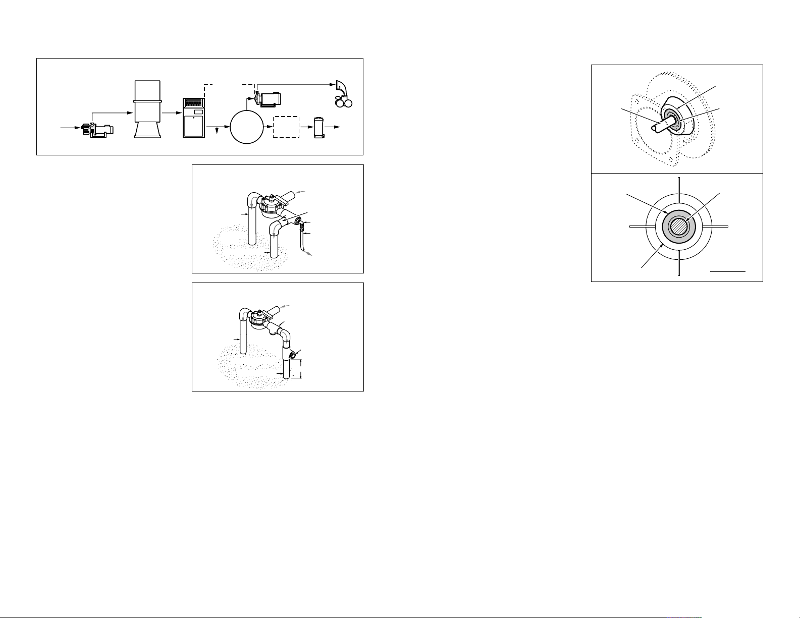
B. Installation Basics
Plumbing Configuration
The booster pump should be
plumbed into the system so it
always receives positive water flow
from the filtration pump. To ensure
proper water flow:
• The booster pump inlet connection line should be at
least 3/4 inch pipe.
• Follow our recommended
plumbing configurations at left.
Do not tap into the top of a
horizontal line; tapping into
the top of a horizontal line
may cause pump damage.
Note: If the plumbing configuration
causes tight bends in the Polaris
reinforced hose, use 90˚ street ells
to minimize the bends and loops.
Checking Water Flow
To check the water flow, disconnect the supply hose to the booster pump and
turn on the filtration pump. If there is no flow:
• Verify the installation is correct.
• Install a valve on the return line after the booster pump inlet. This valve
may need to be closed slightly.
• Use smaller eyeball fittings in the return lines.
• Plug a return line.
C. Troubleshooting
PROBLEM: Pump leaks.
SOLUTION:
Identify location of leak.
Seal Area
1. If the leak is at point A:
• Replace the seals and shaft
o-ring.
• When replacing the seals,
check the impeller seal
pocket. If it is damaged,
replace the impeller. If the
impeller seal pocket is damaged, the pump was run dry.
Check that the circulation
pump is operating and verify
that the time clock sequence
is correct.
2. If the leak is at point B:
• Inspect the bracket for cracks.
• If cracked, replace the bracket and seals.
• If not cracked, replace the seals.
Connection Area
Check all intake and discharge hoses and connections:
1. Replace any cracked parts.
2. Check for hardened washers on old style (black) connections.
3. Reseal loose connections with rubber silicone sealant.
PROBLEM: Excessive vibration or noise.
SOLUTION:
1. Verify rubber feet are on the pump base.
2. Verify that the cleaner is installed (low back pressure causes
excessive noise).
3. Replace the hard plumbing with flexible hoses to dampen the vibration.
4. Check the impeller for foreign material.
5. Remove the wet end and run the motor alone to check for
excessive vibration.
4342
Horizontal Leg
To Booster
Pump
Polaris
Reinforced
Hose
Pool Return
To Spa
From Filter
or Heater
Preferred Plumbing
Configuration
Street Ell
Ground
Level
Pool Return
From Filter or Heater
Pump Inlet
Option #3
Pump Inlet
Option #2
To Spa
Ground Level
Alternate Plumbing Options
Leave 6" for optional
valve installation
Minimum
of 3 feet
From
Pool
Filtration Pump
Pool Filter Heater
Polaris
Booster
Pump
Typical Installation
Note:
Plumb the booster
pump upstream of all air
inducing equipment.
To
Pool
Chlorinator
Solar
System
Plumbing
Options
1, 2 or 3
To
Spa
Shaft
Seal
Bracket
Point A
(Between
the Shaft
and Seal)
Bracket
Inside View
Point B
(Between
the Bracket
and Seal)
Page 27

D. Seal Replacement
REMOVAL:
1. Turn off the power to
the pump.
2. Remove the volute bolts
and volute.
3. Remove the motor shaft cap
at the back of the motor and
secure the shaft.
4. Spin off the impeller.
5. Remove the bracket bolts
and bracket.
6. Remove the white ceramic
seal and rubber cup ring from
the impeller.
7. Tap the seal out of the bracket
and remove any silicone from
the seal pocket.
INSTALLATION:
1. Support the seal pocket in the
bracket with 1 inch PVC coupling or 1-1/2 inch PVC pipe (at least 2-5/8 inch long).
2. Coat the stainless steel seal retainer with rubber silicone sealant.
3. Tap the seal into place using 1 inch PVC coupling or 1-1/4 inch PVC pipe.
4. Press the white ceramic seal into the impeller. Be careful not to touch
the seal face.
PROBLEM: Lack of pressure.
SOLUTION:
1. Verify that the booster pump is correctly installed (motor is wired for
proper voltage) and receiving supply water; it is not self-priming. (Refer to
page 42 for installation basics.)
2. Verify that there are no leaks at the inlet or outlet of the pump.
3. Check the pump hose washers for swelling (old style black hoses).
4. If there is a valve installed on the discharge side of the pump, verify that
the valve is open.
5. Check the impeller for foreign material.
6. Verify that the booster pump discharge is plumbed into the dedicated
cleaner line rather than a normal return line.
PROBLEM: Motor runs then shuts off.
SOLUTION:
1. Verify that the cleaner is connected when the pump is running.
2. Check the amperage and voltage levels. Refer to the motor label.
3. Install a pump pressure restrictor (part #P-53) or a valve on the discharge
side of the booster pump.
4. Ensure that the motor vents are free from debris and receiving
sufficient ventilation.
5. See solutions under “Lack of pressure” problem.
PROBLEM: Motor hums, but does not turn.
SOLUTION:
1. Turn off the power to the pump.
2. Spin the shaft by hand. If it turns freely, there is a motor or
electrical problem.
3. If it does not turn:
• Disassemble the volute.
• Check the impeller for foreign material.
• If the impeller or volute are damaged from contact, remove and
replace them. Then reset the impeller distance if it is a keyed shaft
motor with a brass shaft extension. The impeller should be about
1/8 inch from the bracket face.
4544
1" PVC Coupling or
1-1/4" PVC Pipe
1" PVC Coupling or
1-1/2" PVC Pipe
Rubber
Mallet
Bracket
Flat Surface
Seal
Bracket
1" PVC Coupling or
1-1/4" PVC Pipe
1" PVC Coupling or
1-1/2" PVC Pipe
Page 28

XI. INDEX
Back-up Timer, Conversion In-head/In-line ..........................31
Booster Pump, Exploded Parts Diagram ..............................41
Booster Pump, Installation ....................................................42
Booster Pump, Seal Replacement........................................45
Booster Pump, Troubleshooting ...........................................43
Circles....................................................................................23
Climbing ................................................................................22
Connection Points ...................................................................3
Double-side Wheels ..............................................................36
Drive Belts .............................................................................37
Drive Jet.................................................................................29
Drive Train .............................................................................33
Exploded Parts Diagram 380 .................................................. i
Exploded Parts Diagram 360 ................................................. v
Frame Exchange ...................................................................38
Gear Kit..................................................................................40
Head Float .............................................................................10
Hose Cutting............................................................................3
In-head Back-up Timer, Check .............................................31
In-line Back-up Valve (G-52), Check ....................................30
In-line Back-up Valve (G-41), Check ....................................31
Installation 380 ........................................................................3
Installation 360 ........................................................................6
Jets ........................................................................................29
Moves Slowly.........................................................................21
Parts To Stock........................................................................vii
Phone Screening Questions .................................................11
Pressure Check.....................................................................25
Single-side Wheel .................................................................35
Stuck In Corners/Steps .........................................................20
Sweep Hose Adjustment Screw............................................10
Sweep Hose Sprays..............................................................21
Tangles..................................................................................20
Thrust Jet...............................................................................10
Thrust Jet Sprays Out Of Pool ..............................................21
Tools ........................................................................................2
Transfer Pulley/Drive Shaft Assembly ..................................39
Troubleshooting Procedures - Polaris 380 ...........................17
Troubleshooting Procedures - Polaris 360 ...........................18
Water Flow Diagram..............................................................28
Water Management System .................................................38
Wheel RPM ...........................................................................26
4746
 Loading...