

Page 1

Page 2
WARNING
The engine exhaust from this
product contains chemicals known
to cause cancer, birth defects or
other reproductive harm.
Page 3

1
Page 4

2
-NOTES-
Page 5

3
WELCOME
Thank you for purchasing a Polaris vehicle, and welcome to our
world-wide family of Polaris enthusiasts. Polaris proudly produces an
exciting line of recreational products, including snowmobiles,
all-terrain vehicles, personal watercraft, utility vehicles, and Victory
motorcycles.
We believe Polaris sets the standard of excellence for all vehicles
manufactured in the world today. Many years of experience in
engineering, design, and development have gone into making your
UTV the finest machine we’ve ever produced.
Follow the instructions and recommendations in this Owner ’s Manual
for safe and enjoyable operation of your vehicle. Your Owner’s Manual
contains instructions for minor maintenance, but major repairs are
covered in the Polaris Service Manual and should be performed by a
Factory Certified Master Service Dealer (MSD) Technician.
Your Polaris UTV dealer knows your vehicle best and is interested in
your complete satisfaction. Return to your dealership for all of your
service needs during, and after, the warranty period.
Polaris also takes great pride in our PAA (Parts Apparel and
Accessories) which are available in our online store at
www.purepolaris.com. Have your accessories and clothing delivered
right to your door!
Polaris and Polaris The Way Out are registered trademarks of Polaris
Industries Inc.
Copyright 2002
Polaris Industries Inc.
All Rights Reserved Printed in the U.S.A.
Page 6

4
THIS VEHICLE IS NOT A TOY AND CAN BE
HAZARDOUS TO OPERATE. This vehicle handles differently
from other vehicles, including motorcycles and cars. A collision or
rollover can occur quickly, even during routine maneuvers such as
turning and driving on hills or over obstacles if you fail to take proper
precautions.
SEVERE INJURY OR DEATH can result if you do not follow
these instructions:
n Read this manual and all labels carefully. Follow the operating
procedures described.
n Never allow anyone without a valid driver’s license to operate this
vehicle.
n Minimum age recommendation for passengers is five years old.
Passengers under five years of age require special restraints which
are not available with this vehicle. Driver and passenger should
wear their seat belts at all times.
n Never permit a guest to operate this vehicle unless the guest has
read this manual and all product labels.
n To reduce tipover risk, be especially careful when encountering
obstacles and slopes and when braking on hills or during turns.
n Always fasten your seat belts securely around you.
n This vehicle is for off road use only. Never operate on public
roads. Always avoid paved surfaces.
n Helmets are recommended whenever driving this vehicle in an
aggressive manner. Eye protection is recommended at all times.
n Never consume alcohol or drugs before or while operating this
vehicle.
n Never operate at excessive speeds. Always travel at a speed proper
for the terrain, visibility and operating conditions, and your
experience.
n Never attempt wheelies, jumps or other stunts.
n Always inspect your vehicle each time you use it to make sure it’s
in safe operating condition. Always follow the inspection and
maintenance procedures and schedules described in this manual.
n Always keep both hands on the steering wheel and both feet on the
floorboards of the vehicle during operation.
Page 7

5
n Always travel slowly and use extra caution when operating on
unfamiliar terrain. Be alert to changing terrain.
n Never operate on excessively rough, slippery or loose terrain.
n Always follow proper procedures for turning as described in this
manual. Practice turning at slow speeds before attempting to turn
at faster speeds. Never turn at excessive speeds.
n Always have this vehicle checked by an authorized Polaris dealer if
it has been involved in an accident.
n Never operate this vehicle on hills too steep for the vehicle or for
your abilities. Practice on smaller hills before attempting larger
hills.
n Always follow proper procedures for climbing hills as described in
this manual. Check the terrain carefully before attempting to climb
a hill. Never climb hills with excessively slippery or loose
surfaces. Never open the throttle suddenly or make sudden gear
changes. Never go over the top of a hill at high speed.
n Always follow the proper procedures outlined in this manual for
traveling downhill and for braking on hills. Check the terrain
carefully before descending a hill. Never travel downhill at high
speed. Avoid going downhill at an angle, which would cause the
vehicle to lean sharply to one side. Travel straight down the hill
where possible.
n Always follow proper procedures for crossing the side of a hill as
described in this manual. Avoid hills with excessively slippery or
loose surfaces. Never attempt to turn the vehicle around on any
hill until you have mastered (on level ground) the turning
technique described in this manual. Avoid crossing the side of a
steep hill if possible.
n Always check for obstacles before operating in a new area. Never
attempt to operate over lar ge obstacles such as rocks or fallen trees.
Always follow the proper procedures outlined in this manual when
operating over obstacles.
n Always be careful of skidding or sliding. On slippery surfaces
such as ice, travel slowly and exercise caution to reduce the chance
of skidding or sliding out of control.
Page 8

6
n Never operate your vehicle in fast-flowing water or in water deeper
than that specified in this manual. Wet brakes may have reduced
stopping ability. Test your brakes after leaving water. If necessary,
apply them lightly several times to let friction dry out the pads.
n Always be sure there are no obstacles or people behind your
vehicle when operating in reverse. When it’s safe to proceed in
reverse, move slowly. Avoid turning at sharp angles in reverse.
n Always use the proper size and type of tires specified in this
manual. Always maintain proper tire pressure as specified on page
97.
n Never modify this vehicle through improper installation or use of
accessories.
n Never exceed the stated load capacity for this vehicle. Cargo
should be properly distributed and securely attached. Reduce
speed and follow the instructions in this manual for hauling cargo
or pulling a trailer. Allow a greater distance for braking.
n Always wear the seat belts when operating this vehicle. Seat belts
reduce the severity of injury in case of a sudden stop or collision.
n Always keep arms and legs inside the cab frame while the vehicle
is in motion.
n Always apply the parking brake before getting out of the vehicle.
Seepage46.
n Always activate the foot pedal brake before releasing the park
brake.
n Always turn off the engine before refueling. Make sure the
refueling area is well ventilated and free of any source of flame or
sparks. Gasoline is extremely flammable. See page 54 for
refueling instructions.
FOR MORE INFORMATION ABOUT SAFETY, call Polaris at
1-800-342-3764.
Page 9

7
Additional Important Information
We are concerned for the safety of our customers and for the general
public. Therefore, we strongly recommend that consumers do not
install on a Polaris UTV any equipment that may increase the speed or
power of the vehicle, or make any other modifications to the vehicle
for these purposes. Any modifications to the original equipment of the
UTV substantially increase the risk of bodily injury. Modifications
may create a substantial safety hazard.
The warranty on your Polaris UTV is terminated if any equipment has
been added to the vehicle, or if any modifications have been made to
the vehicle, that increase its speed or power.
We also advise you to strictly follow the recommended maintenance
program outlined in this manual. This preventive maintenance
program is designed to ensure that all critical components on the
vehicle are thoroughly inspected by your dealer at various mileage
intervals.
NOTE:
The addition of certain accessories, including (but not limited to)
mowers, blades, tires, sprayers, or large racks, may change the
handling characteristics of the vehicle.
Be sure any accessories added to this vehicle have been approved by
Polaris, and familiarize yourself with their function and effect on the
vehicle.
Page 10

8
-NOTES-
Page 11

9
TABLE OF CONTENTS
Vehicle Identification Numbers 11.............
Safety 12....................................
Features and Controls 36.....................
Operation 47.................................
Noise Emission 55...........................
Maintenance and Lubrication 56...............
Specifications 96.............................
Troubleshooting 98..........................
Warranty 100................................
Page 12

10
-NOTES-
Page 13
11
VEHICLE IDENTIFICATION NUMBERS
Important: Record your vehicle’s identification numbers in the
spaces provided.
Frame VIN:
Engine Serial Number (right front side of engine crankcase)
NOTE: Remove the spare key and store in a safe place.
The vehicle frame vehicle identifaction number (VIN) and engine
serial number are important for model identification when
registering your vehicle, when obtaining insurance, and when
ordering replacement parts. In the event your vehicle is stolen, these
numbers are essential to the recovery and identification of your
vehicle.
Vehicle Model Number:
Dealer Imprint
VIN
Page 14
12
SAFETY
Operator Safety
The following signal words and symbols appear throughout this
manual and on your UTV. Your safety is involved when these words
and symbols are used. Become familiar with their meanings before
reading the manual.
The safety alert symbol, on your UTV or in this manual, alerts you
to the potential for personal injury.
The safety alert warning indicates a potential hazard that may result
in serious injury or death.
The safety alert caution indicates a potential hazard that may result
in minor personal injury or damage to the machine.
CAUTION
NOTE
A note will alert you to important information or instructions.
A caution indicates a situation that may result in damage to the
machine.
CAUTION
WARNING
Page 15

13
SAFETY
Operator Safety
WARNING
Driving a UTV requires your full attention. DO NOT drink alcohol
or use drugs or medications before or while driving. They will
reduce your alertness and slow your reaction time. In most states
and provinces, it’s prohibited by law to drive while intoxicated or
under the influence of drugs.
Make sure your UTV is in excellent operating condition at all
times. We strongly recommend that the operator check all safety
components before each ride.
Polaris UTVs are designed to provide safe operation when used
as directed. Failure of critical machine components may result
from operation with any modifications, especially those that
increase speed or power. DO NOT MODIFY YOUR MACHINE.
The UTV may become aerodynamically unstable at speeds higher
than those for which it is designed. Loss of control may occur at
higher speeds. Modifications may also create a safety hazard and
lead to bodily injury .
The warranty on your entire machine is terminated if any
equipment has been added, or any modifications have been
made, to increase the speed or power of the UTV.
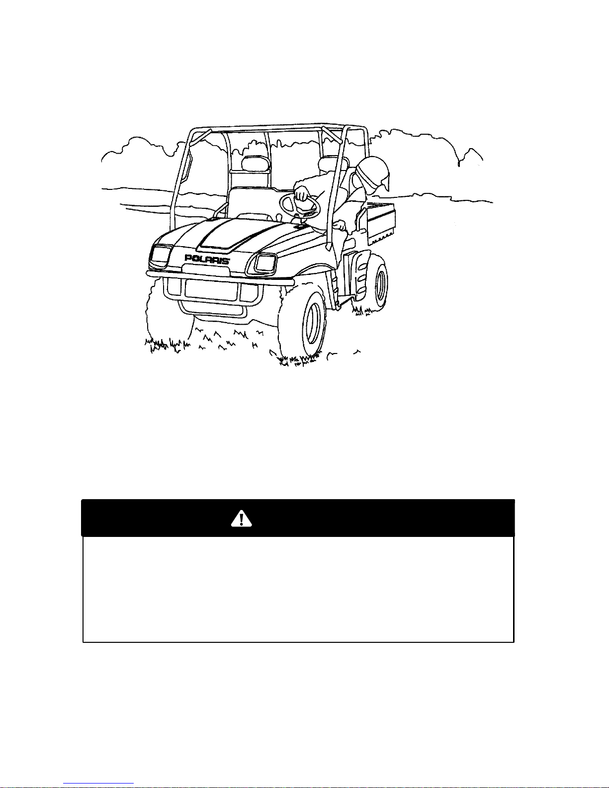
Page 16
14
SAFETY
Operator Safety
POTENTIAL HAZARD
Stalling, rolling backwards while climbing a hill
WHAT CAN HAPPEN
Vehicle overturn
HOW TO AVOID THE HAZARD
Maintain a steady speed when climbing a hill.
Ifyouloseallforwardspeed:
Apply the brakes.
Lock the parking brake after when fully stopped.
If you begin rolling
backwards:
Never apply engine power.
Apply the brake gradually.
When fully stopped, lock parking brake.
In the event of an accident, have a qualified service dealer check
the complete machine for possible damage, including (but not
limited to) brakes, throttle and steering.
WARNING
Page 17

15
SAFETY
Operator Safety
POTENTIAL HAZARD
Operating this vehicle on paved surfaces
WHAT CAN HAPPEN
Loss of control
HOW TO AVOID THE HAZARD
This vehicle’ s tires are designed for off-road use only, not
for use on pavement. Paved surfaces may seriously affect
handling and control of the vehicle, and may cause the
vehicle to go out of control.
Avoid operating the vehicle on pavement. If you must
operate on a paved surface, travel slowly and do not make
sudden turns or stops.
WARNING
POTENTIAL HAZARD
Operating this vehicle without proper instruction
WHAT CAN HAPPEN
Loss of control, accident
HOW TO AVOID THE HAZARD
The risk of an accident is greatly increased if the operator does
not know how to operate the vehicle properly in different
situations and on different types of terrain.
All operators must read and understand the Owner’s Manual
and all warning and instruction labels on the vehicle.
WARNING
Page 18
16
SAFETY
Operator Safety
POTENTIAL HAZARD
Operating this vehicle on public streets, roads or highways
WHAT CAN HAPPEN
Collision with another vehicle
HOW TO AVOID THE HAZARD
Never operate this vehicle on any public street, road or
highway, including dirt or gravel.
In many states it’s illegal to operate vehicles of this type on
public streets, roads and highways.
WARNING
POTENTIAL HAZARD
Operating this vehicle after consuming alcohol or drugs
WHAT CAN HAPPEN
Could seriously affect your judgment.
Could cause you to react more slowly.
Could affect your balance and perception.
Could result in an accident.
HOW TO AVOID THE
HAZARD
Never consume alcohol or drugs before or while driving this
vehicle.
WARNING
Page 19

17
SAFETY
Operator Safety
POTENTIAL HAZARD
Operating this vehicle at excessive speeds
WHAT CAN HAPPEN
Loss of control, accident
HOW TO AVOID THE HAZARD
Always travel at a speed proper for the terrain, visibility and
operating conditions, and your experience.
WARNING
POTENTIAL HAZARD
Attempting jumps and other stunts
WHAT CAN HAPPEN
Loss of control, accident and/or vehicle overturn
HOW TO AVOID THE HAZARD
Never attempt jumps and other stunts. Avoid exhibition driving.
WARNING
Safe operation of this vehicle requires good judgement and
physical skills. Persons with cognitive or physical disabilities who
operate this vehicle have an increased risk of overturns and loss
of control, which could result in serious injury or death.
WARNING
Page 20
18
SAFETY
Operator Safety
POTENTIAL HAZARD
Failure to inspect the vehicle before operating
Failure to properly maintain the vehicle
WHAT CAN HAPPEN
Accident, equipment damage
HOW TO AVOID THE HAZARD
Always inspect your UTV before each use to make sure it’s in safe
operating condition.
Always follow the inspection and maintenance procedures and
schedules described in the Owner’s Manual.
POTENTIAL
HAZARD
Failure to use extra caution when operating this vehicle on
unfamiliar terrain
WHAT CAN
HAPPEN
Loss of control, vehicle overturn
HOW TO AVOID THE HAZARD
Travel slowly and use extra caution when operating on unfamiliar
terrain.
Always be alert to changing terrain conditions when operating the
vehicle. Yo u may come upon hidden rocks, bumps, or holes
suddenly , without enough time to react.
WARNING
WARNING
Page 21
19
SAFETY
Operator Safety
POTENTIAL HAZARD
Operating this vehicle with improper tires or with improper or
uneven tire pressure
WHAT CAN
HAPPEN
Loss of control, accident and/or overturn
HOW TO AVOID THE HAZARD
Always use the size and type of tires specified in the Owner’s
Manual for this vehicle. See page 97.
Always maintain proper tire pressure as described on the decal
and in the Owner’s Manual. See page 97.
WARNING
POTENTIAL HAZARD
Failure to follow the minimum age recommendations for this
vehicle
WHAT CAN
HAPPEN
Serious injury or death (the child or others)
HOW TO AVOID THE HAZARD
Only persons with a valid driver’s license should operate a Polaris
UTV.
Even though a child may be within the age group for which some
vehicles are recommended, he or she may not have the skills,
abilities, or judgment needed to operate the vehicle safely and
may be involved in a serious accident.
WARNING
Page 22
20
SAFETY
Operator Safety
In the event of an accident, have a qualified service dealer inspect
the complete machine for possible damage, including (but not
limited to) brakes, throttle, and steering.
WARNING
POTENTIAL HAZARD
Operating this vehicle with improper modifications
WHAT CAN HAPPEN
Loss of control, accident
HOW TO AVOID THE HAZARD
Improper installation of accessories or modification of this vehicle
may cause changes in handling that in some situations could lead
to an accident.
Never modify this vehicle through improper installation or use of
accessories. All parts and accessories should be genuine Polaris
Sales Inc. or equivalent components designed for use on the
vehicle, and they should be installed and used according to
instructions. See your authorized Polaris dealer.
WARNING
Page 23
21
SAFETY
Operator Safety
Driving On Slippery Surfaces
Extra caution is required when operating on slippery surfaces.
Loss of tire traction and vehicle control can result in an accident,
including an overturn.
Never apply brakes during a skid. Complete loss of control can
result.
Avoid operating on excessively slippery surfaces.
Always reduce speed and use additional caution.
WARNING
When driving on slippery surfaces such as wet trails, loose gravel, or
ice, be alert for the possibility of skidding and sliding. Under these
conditions, follow these precautions:
1. Slow down when entering slippery areas.
2. Maintain a high level of alertness, reading the trail and avoiding
quick, sharp turns, which can cause skids.
3. Correct a skid by turning the steering wheel in the direction of the
skid.
4. Drive with AWD engaged to assist in controlling the vehicle.
CAUTION
Engaging AWD while the wheels are spinning can cause severe
damage to the drive train.
Before operating your vehicle on a frozen body of water, be sure the
ice is thick enough to support the machine and its operator, as well
as the force created by a moving vehicle. Severe injury or death
can result if the vehicle and/or its operator break through the ice.
WARNING
Page 24

22
SAFETY
Operator Safety
Operating on Hills
Climbing hills improperly can cause loss of control or vehicle
overturn. Always check the terrain carefully before climbing a hill.
Never climb hills with excessively slippery or loose surfaces.
Never open the throttle suddenly.
Never go over the crest of a hill at high speed. An obstacle, a
sharp drop, or another vehicle or person could be on the other
side of the hill.
WARNING
When traveling uphill:
1. Drive straight uphill.
2. Avoid steep hills.
3. Keep both feet on the floor.
4. Proceed at a steady rate of speed and throttle opening.
Traveling downhill improperly could cause loss of control or vehicle
overturn. Always check the terrain carefully before descending a
hill.
Never descend a hill at high speed. Excessive speed may result in
loss of vehicle control and lead to serious injury or death.
Avoid descending a hill at an angle, which would cause the vehicle
to lean sharply to one side. Travel straight downhill when possible.
WARNING
When descending a hill:
1. Drive directly downhill.
2. Slow down.
3. Apply the brakes lightly to aid in slowing.
Page 25
23
SAFETY
Operator Safety
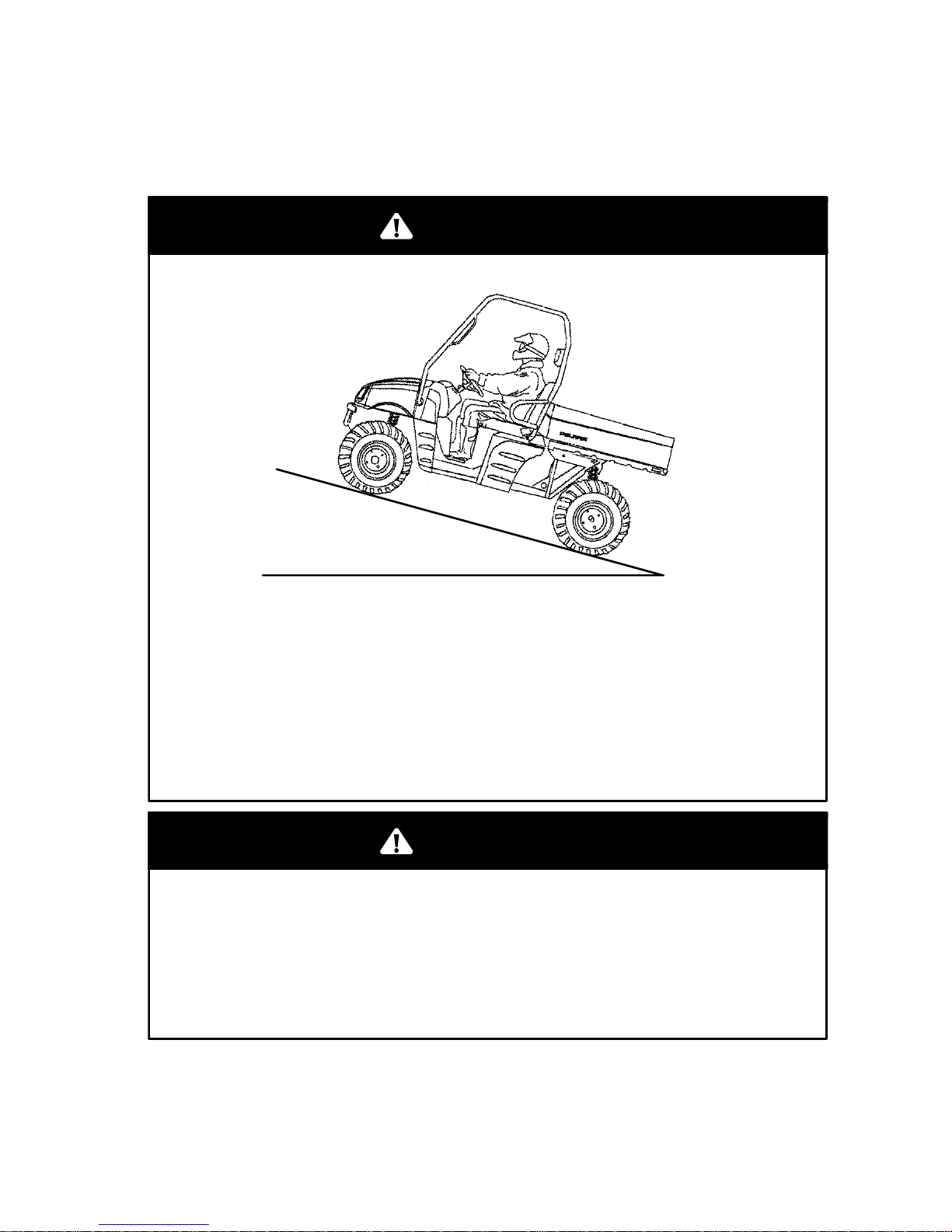
Operating on Hills
Braking and handling are greatly affected when operating in hilly
terrain. Loss of vehicle control or overturning of the vehicle could
occur.
Avoid climbing steep hills (15_ maximum).
Use extreme care when operating your vehicle in hilly terrain.
WARNING
15_ Maximum
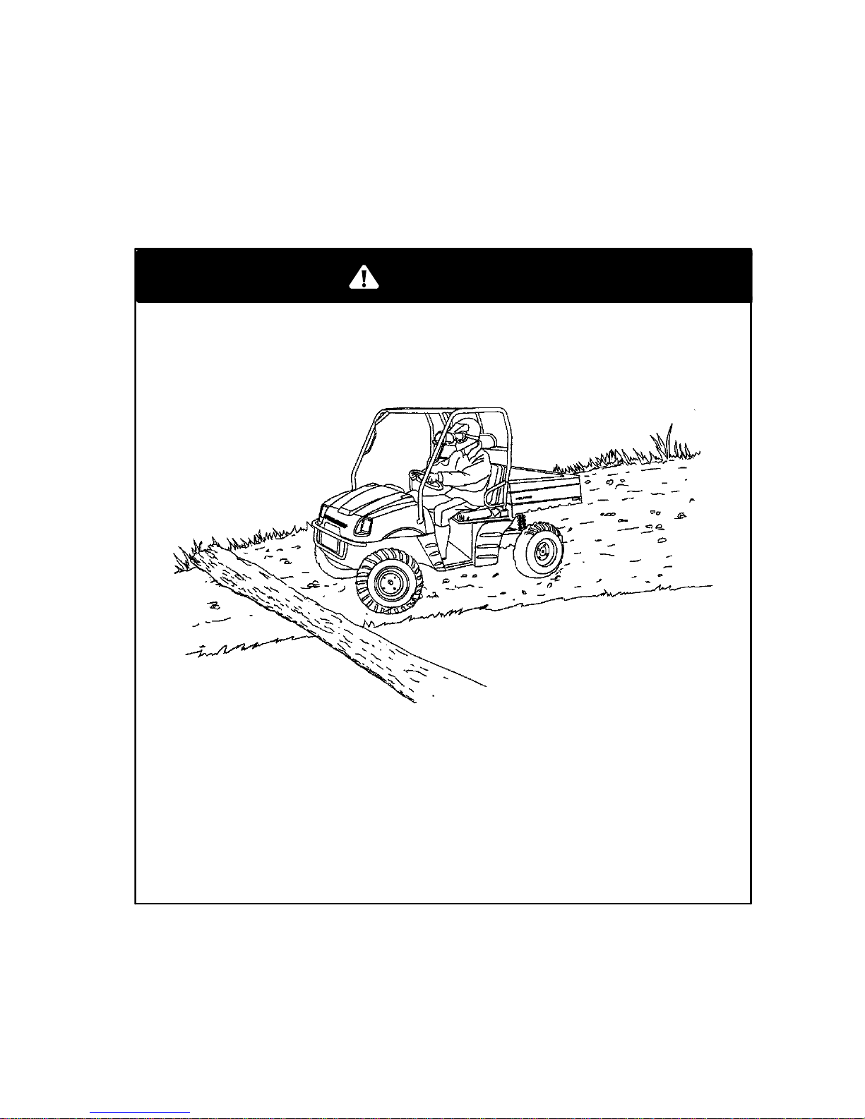
Improperly crossing hills or turning on hills could cause loss of
control or vehicle overturn.
If at all possible, avoid crossing the side of a steep hill. Avoid
hills with excessively slippery or loose surfaces.
WARNING
Page 26
24
SAFETY
Operator Safety
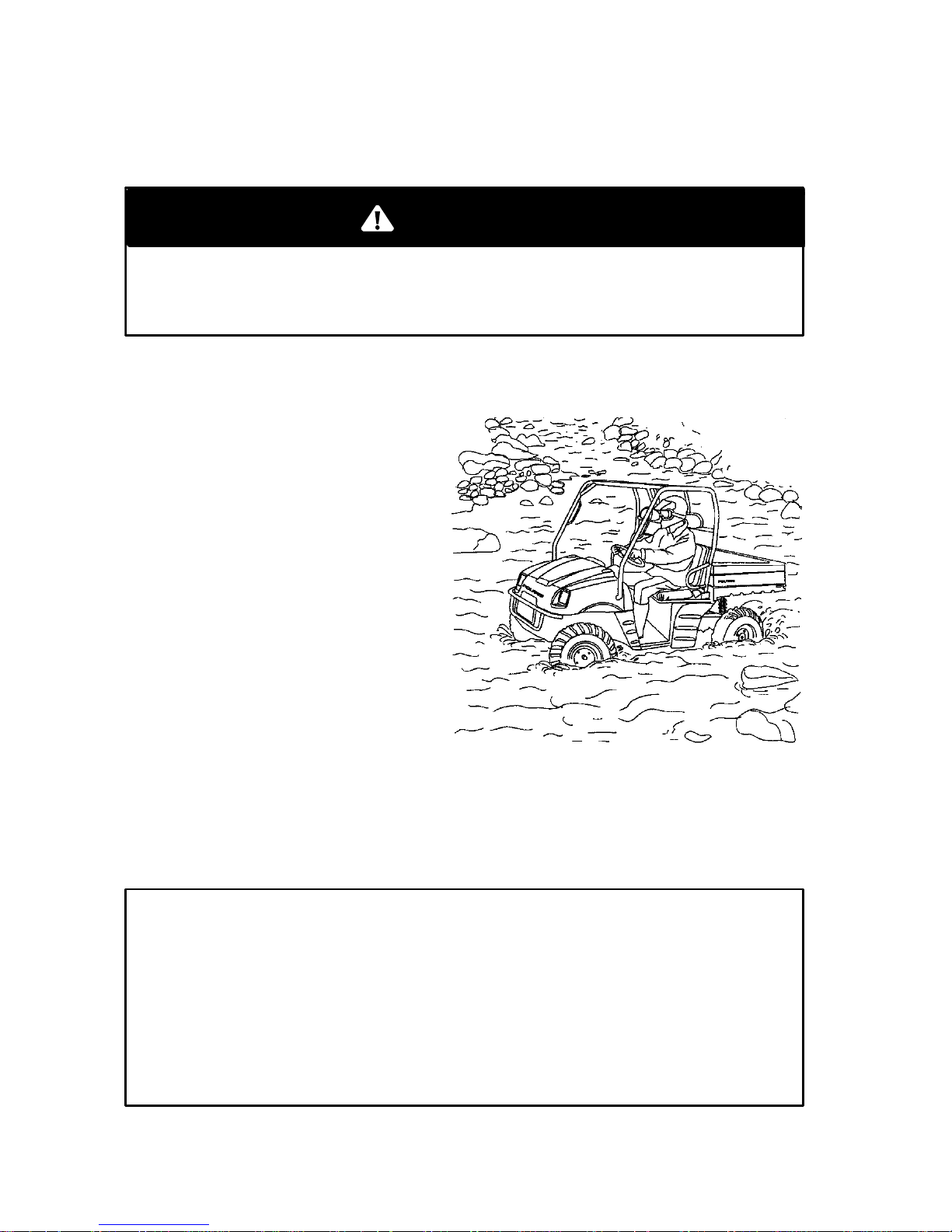
Crossing Streams
Never try to cross a deep or fast-flowing stream. The large tires
can cause the vehicle to float, resulting in loss of control.
WARNING
Your Polaris UTV can operate through water up to depths reaching the
floorboards. Before fording streams:
1. Always determine water
depths and current.
2. Always choose a crossing
where both banks have
gradual inclines.
3. Always proceed slowly,
avoiding rocks and
obstacles.
4. After crossing, always dry
the brakes by applying
light pressure to the lever
until braking action is
normal.
NOTE: After running the vehicle in water, it is critical that your
machine is serviced as outlined in the Periodic Maintenance Schedule
beginning on page 56. Give special attention to engine oil,
transmission oil, front and rear gearcases, and all grease fittings.
CAUTION
Should your vehicle become immersed, take it to your dealer as
soon as possible for service. Do not start the engine!
Immersion can result in major damage if not correctly serviced.
If this is impossible, service your machine as outlined on page
72, and take the machine to your dealer at your first opportunity.
Page 27
25
SAFETY
Operator Safety
Trail Obstacles
Stay alert! Look ahead and learn to read the trail as you drive. Stay on
the righthand side of the trail and be constantly alert for hazards such
as logs, rocks and low hanging branches.
Hidden or unseen hazards on the trail can be dangerous.
Personal injury or the vehicle overturning can occur from unseen
obstacles.
Stay alert and constantly look for obstacles on the trail.
WARNING
Page 28
26
SAFETY
Operator Safety
Operating in Reverse
1. When backing up, always avoid backing downhill.
2. Back slowly.
3. When in reverse, apply the brakes lightly for stopping.
4. Avoid turning at sharp angles in reverse.
5. Never open the throttle suddenly while backing.
6. Always inspect left and right fields of vision before backing.
Backing your UTV can be dangerous! You could collide with an
obstacle or person behind you, or the vehicle could overturn on a
steep incline.
Always back slowly, avoiding excessive speed.
Avoid backing on steep inclines.
WARNING
Page 29
27
SAFETY
Operator Safety
ParkingOnAnIncline
1. Place the transmission in gear.
2. Set the parking brake.
3. Avoid parking on an incline. If it is necessary to park on an
incline, always block the rear wheels on the downhill side.
Always check to be sure that the parking brake has been
disengaged before operating the vehicle. An accident could result
if the parking brake is left on while the vehicle is operated.
Always block the downhill side of the wheels if leaving the vehicle
on a hill, or park the vehicle in a sidehill position.
WARNING
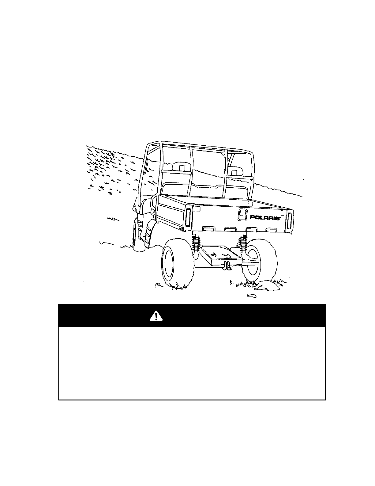
Page 30
28
SAFETY
Operator Safety
Carrying Loads
The UTV has been designed to carry or tow specific capacities. Always
read and understand the load distribution warnings listed on the
warning labels. Never exceed the following capacities.
Maximum Capacities
(Level Ground)
Cargo Box
UTV 2X4 1350 lbs. (614 kg) 850 lbs. (386 kg)
UTV 4X4 1500 lbs. (681 kg) 1000 lbs. (454 kg)
Load Distribution
1. Always load the cargo box with the load as far forward as possible.
2. Always operate the vehicle with extreme care when hauling or
towing loads.
3. Slow down and drive in low gear.
Never operate this vehicle with the cargo box in the raised
position. The cargo box could close unexpectedly while driving,
severely injuring the driver. The rear tires will catch the rear of
the box, damaging the vehicle and creating hazardous driving
conditions.
Do not overload the vehicle.
WARNING
Page 31

29
SAFETY
Operator Safety
Dumping the Ca rgo Box
1. Select a level site to dump the cargo box. Do not attempt to dump
or unload the vehicle while parked on an incline.
2. Set the parking brake.
3. Press and hold the cargo box dump switch in the upward position
to dump.
4. Press and hold the cargo box dump switch in the downward
position to return the box to a l evel position.
Never carry passengers in the cargo box.
Passengers should always ride in the cab with seat belts
fastened securely.
WARNING
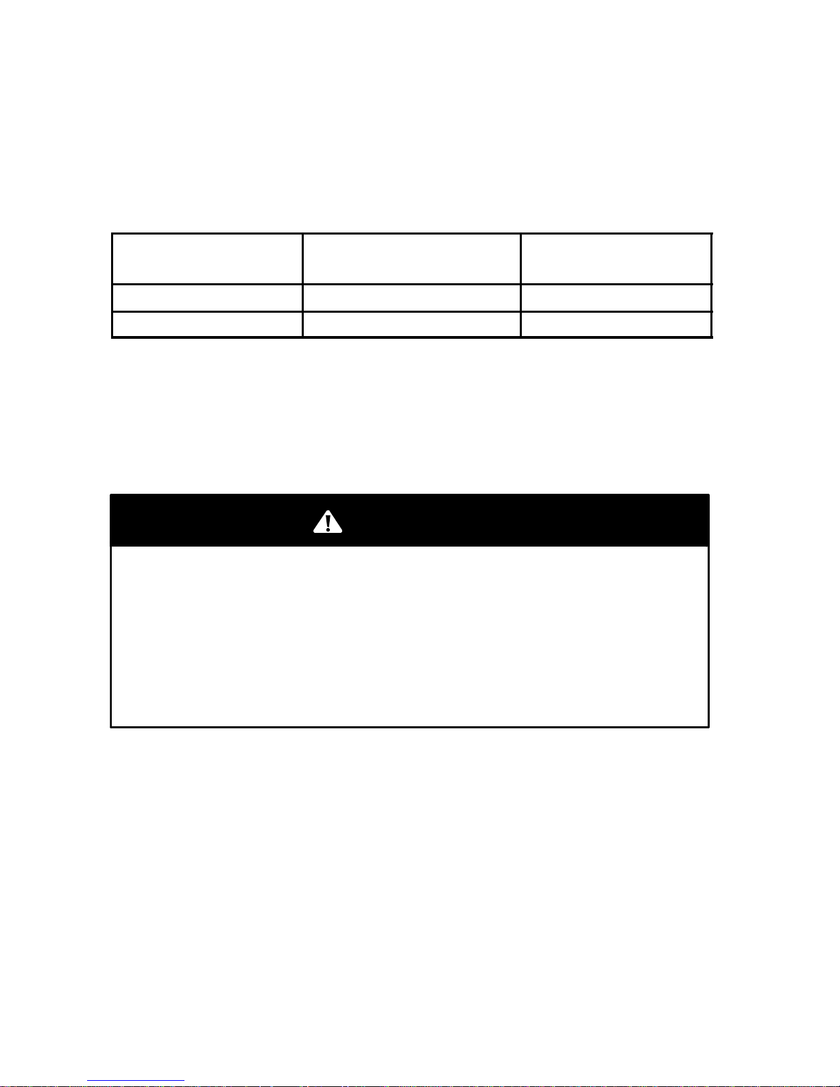
Page 32

30
SAFETY
Operator Safety
Towing Loads
Maximum Towing Capacities (Level Ground)
Total Towed
Load Weight
(level ground)
Total Towed
Load Weight
(15° grade)
Total Hitch
Vertical
Weight
Towing
Speed
UTV 2X4 1400 lbs.
(636 kg)
800 lbs.
(364 kg)
150 lbs
(68.1 kg)
10 mph
(16 kph)
or less
UTV 4X4 1500 lbs.
(681 kg)
850 lbs.
(386 kg)
150 lbs
(68.1 kg)
10 mph
(16 kph)
or less
Do not tow in high gear. Drive belt life will be affected.
Maximum grade while trailer towing is 15°. Do not tow any trailer on
a grade steeper than 15°.
Never carry a passenger in a trailer.
Never load more than 150 lbs. (68.1 kg) tongue weight on the
towing bracket.
Do not operate the vehicle faster than 10 mph (16 km/h) when
towing. Towing a trailer increases braking distance.
Do not tow more than the recommended weight. See page 96.
Attach a trailer to the trailer hitch bracket only. Do not attach a
trailer to any other location or you may lose control of the
vehicle.
WARNING
Page 33

31
SAFETY
Operator Safety
Parking the UTV
1. Stop the vehicle on a level surface.
2. When the engine has stopped, apply the parking brake to help
prevent the vehicle from rolling.
Always apply the parking brake before leaving the vehicle. If the
vehicle should roll, it may cause damage or injury.
WARNING
3. Remove the ignition switch key to prevent unauthorized use.
NOTE: When parking inside a garage or other structure, be sure that
the structure is well ventilated and that the vehicle is not close to any
source of flame or sparks, including any appliance with pilot lights.
Gasoline is extremely flammable and can be explosive under
certain conditions.
WARNING
Page 34

32
SAFETY
Safety Decals and Locations
S VEHICLE ROLLOVER could cause severe injury or death
This cab frame is not designed or intended to provide rollover protection.
S ALWAYS WEAR YOUR SEAT BELT for maximum protection.
WARNING
IMPROPER TIRE PRESSURE OR OVERLOADING can cause loss of
control resulting in SEVERE INJURY OR DEATH.
TIRE PRESSURE (PSI): FRONT 10 REAR 10
MAXIMUM WEIGHT CAPACITY (Gross Vehicle Weight)
INCLUDING MACHINE, DRIVER AND CARGO IS 2750 LBS.
Reduce speed and allow greater distance for braking when carrying
cargo. Overloading or carrying tall, off-center, or unsecured loads
will increase your risk of losing control. Loads should be centered
and carried as low as possible in box. For stability on rough or hilly
terrain, reduce speed and cargo. Be careful if load extends over the
side of the box.
Read Owner’s Manual for more detailed loading information.
7079424
7079425
Location 1
S Moving parts hazard under belt-clutch guard. To
prevent serious injury, do not operate vehicle with
guard removed.
S Do not modify engine or clutch. Doing so can
cause part failure, possibleimbalance, and excessive engine RPM which can result in serious injury
or death.
WARNING
7078689
NO STEP
Location 2
Location 3
Page 35

33
SAFETY
Safety Decals and Locations
1
2
3
ATTENTION
D Operation of this vehicle without
the filter element will severely
damage the engine.
D Clean air filter often, more
frequent cleaning required in
dusty conditions
D Operation of this vehicle without
engine breather filter(s) can
cause engine damage. Consult
owner’s manual for details.
D Specific
carburetor jetting and
adjustments are required depending on
temperature and altitude. See your
Owner’s Manual.
Factory setting:
40_ to 80_ F. at 0-3000 feet
(5_ to 27_ C. at 0-900 meters).
7079902
4
Location 4
Page 36

34
SAFETY
Safety Decals and Locations
MANUFACTURED
BY: POLARIS IND INC.
DATE:
VIN:
THIS VEHICLE IS A GENERAL PURPOSE OFF-ROAD
UTILITY VEHICLE AND IS NOT INTENDED FOR USE ON
PUBLIC ROADS.
PRINTED IN U.S.A.
7078472
CE VÉHICULE USAGE GENERAL VEHICULE UTILITAIRE POUR SERVICE HORS
ROUTE QUI NEST PAS DESTINE A ETRE UTILISE SUR LES
CHEMINS PUBLICS.
Remove flammable containers from box before refueling.
Location 5 (under hood)
Location 6 (inside, front of box)
5
6
Fuel / Passenger Warning Decal Text
Remove flammable containers from box before refueling.
S Passengers can be thrown off. This can cause serious injury or
death.
S Never carry passengers in cargo box.
Maximum2x4BoxLoad850lbs.
Maximum4x4BoxLoad1000 lbs.
Page 37

35
SAFETY
Safety Decals and Locations
WARNING
Location 7
7
Warning Decal Text
Improper vehicle use can result in SEVERE INJURY or DEATH.
NEVER:
S Operate on public roads. A collision can occur with another vehicle.
S Carry more than two passengers, or passengers under age five.
S Use ALCOHOL or DRUGS before or while operating this vehicle.
S Operate at speeds too fast for your skills or the conditions.
S Operate this vehicle on HILLS steeper than 15 degrees. To prevent
flipover on hilly terrain, use throttle and brakes gradually.
ALWAYS:
S Avoid paved surfaces which may adversely affect handling and con-
trol.
S Use proper RIDING TECHNIQUES to avoid vehicle overturns on
hills and rough terrain and in turns.
S Wear eye protection.
REVERSE operation can be dangerous, even at low speeds. Steering
becomes difficult. To prevent flipover, avoid sharp turns.
The park/emergency brake lever will supply increased braking, but
should be used as an emergency or parking brake only.
READ OWNER’S MANUAL. FOLLOW ALL INSTRUCTIONS
AND WARNINGS. IF OWNER’S MANUAL IS MISSING,
CONTACT A POLARIS DEALER FOR A REPLACEMENT.
THIS GENERAL PURPOSE OFF-ROAD UTILITY VEHICLE DOES
NOT MEET FEDERAL MOTOR VEHICLE SAFETY STANDARDS
FOR ON ROAD VEHICLES.
Page 38

36
FEATURES AND CONTROLS
Features
1. Cab Frame
2. Cab Frame Hand Hold
3. Dashboard
4. Steering Wheel
5. Seat
6. Cargo Box
7. Seat Belts
8. Fuel Tank Cap / Fuel Gauge
9. Battery (under seat)
1
4
7
5
6
2
3
8
9
Page 39

37
FEATURES AND CONTROLS
Features
12
11
10
10
13
13
10. Headlights
11. Radiator
12. Front Bumper/Brush Guard
13. Hood Hold Down Strap
Page 40

38
FEATURES AND CONTROLS
Features
16
16
22
20
18
15
23
14
21
21
19
17
14. Oil Tank
15. Battery (Under Seat)
16. Tail Lights
17. Tail Gate
18. Tailgate Latch Release
19. Airbox (under cargo box)
20. Muffler (Spark Arrester)
21. Rear Caliper
22. Trailer Hitch Receiver
23. Engine Oil Plug
Page 41

39
FEATURES AND CONTROLS
Features
Auxiliary Lighting/Electrical Accessory Terminals
The 12-volt receptacle (1) has
spade connections on the back that
may be used to power an auxiliary
light or other optional lights or
accessories.
To locate these connections, lift the
hood and look behind the dash
board.
Trailer Hitch Bracket
This vehicle is equipped with a
receiver hitch bracket for a trailer
hitch. Trailer towing equipment is
not supplied with this vehicle.
To avoid injury and property damage, observe the precautions on page 30.
Seat Belts
The vehicle is equipped with lap-style seat belts for the operator and
passenger.
Seat belts reduce injury. Always wear your seat belt.
Minimum age recommendation for passengers is five years old.
Passengers under five years of age require special restraints,
which are not available with this vehicle.
WARNING
To wear the seat belt properly, follow this procedure:
1. Place the belt across your lap as low on your hips as possible,
taking care that t he belt is not twisted.
2. Push the latch plate into the buckle until it clicks.
3. Release the strap, it will self tighten. NOTE: The center belt must
be tightened manually by pulling on the strap.
To unfasten, press the square red button in the buckle’s center.
1
Page 42

40
FEATURES AND CONTROLS
Features
Seat Removal
Pull up on the front of the
seat and slide it toward the
front of the vehicle.
Install the seat by sliding
the tabs into the rear of the
seat base. Push down
firmly on the front of the
seat until the pins are fully
seated into the grommets.
Fuel Cap/Fuel Gauge
The fuel tank filler cap (1) is
located on the righthand side
of the vehicle near the
passenger seat. It has a
built-in fuel gauge that
indicates the amount of fuel
remaining in the tank.
When the indicator needle
nears the E (empty) mark,
refuel at the earliest
opportunity.
When refueling, always use
either leaded or unleaded
gasoline with a minimum
pump octane number of 87
R+ M/2 octane.
1
Page 43

41
FEATURES AND CONTROLS
Controls
7
2
1
3
4
5
9
8
6
10
1. Choke Knob
2. Ignition Switch
3. Hour Meter
4. Indicator Lights
5. 12V Accessory Plug
6. Fog/High Beam Light S witch
7. AWD (All Wheel Drive) Switch (if equipped)
8. Shift Lever
9. Differential Lock Lever
10. Cargo B ox Dump Switch
Page 44

42
FEATURES AND CONTROLS
Controls
Transmission Gear Selector Operation
The transmission gear selector
(1) is located on the console to
the right of the steering wheel.
It has four positions (2): high,
low, neutral and reverse.
NOTE: Low is the primary
driving range for this vehicle.
High is intended for use on hard
packed surfaces with light loads.
To change gears, stop the
vehicle and with the engine
idling, move the lever to the
desired gear. Do not attempt to
shift gears with engine speed above idle or while the vehicle is moving.
Always place the transmission in gear with the parking brake locked
whenever the vehicle is left unattended.
Maintaining shift linkage adjustment is important to assure proper
transmission function. See your dealer if you experience any shifting
problems.
NOTE: This vehicle is equipped with a reverse alarm. The alarm is
activated when the transmission is shifted to reverse.
Do not attempt to shift the transmission while the vehicle is
moving or damage to the transmission could result.
Always place the transmission in gear with the parking brake
applied and turn the vehicle off whenever the vehicle is left
unattended.
CAUTION
H
L
N
R
1
2
Page 45

43
FEATURES AND CONTROLS
Controls
Brake Pedal
The brake pedal (1) is the left
pedal on the foot board.
Depress the brake pedal to
slow or stop the vehicle.
Throttle Pedal
The throttle pedal (2) is the
right pedal on the floor board.
Push the pedal down to
increase engine speed. Spring
pressure returns the pedal to
the rest position when released. Always check that the throttle pedal
returns normally before starting the engine. In addition, there must be
adequate throttle pedal play. Refer to page 79 for throttle pedal
adjustment procedure.
Indicator Lights
There are indicator lights on the dash panel
for the following:
1. High
2. Low
3. Neutral
4. Reverse
5. High Temperature
6. Brakes
1
2
H
L
N
R
1
3
5
6
BRAKE
4
2
Page 46

44
FEATURES AND CONTROLS
Controls
Ignition Switch (1)
The ignition switch is a three-position, key-operated switch. The key
can be removed from the switch when it is in the OFF position.
Light Switch (2)
Turn the headlights and taillights on by flipping the light switch up (the
ignition switch key must be in the ON position). Flip the switch down
to turn the lights off.
AWD Switch (3)
Vehicles equipped with AWD can be operated in either 2WD or AWD.
Flip the AWD switch up to engage the AWD. Flip the switch down to
return to 2WD.
Under some conditions, it’s possible for the AWD to remain engaged.
See page 99 for manual disengagement instructions.
Cargo Box Dump Switch (4)
The cargo box can be dumped or lowered by holding the dump switch
down (to dump) or up (to lower).
OFF
ON
START
Engine off. All electrical circuits are off except Acc. 12V.
Electrical circuits are on. Electrical equipment can be used.
Electric starter is engaged by holding ignition switch key
in this position. Upon release, the key will return to the ON
position.
CAUTION
Do not operate the starter continuously for more than five seconds
or the starter will overheat and the battery power will drop
temporarily. Wait at least five seconds between each operation of
the starter to allow it to cool and to allow battery power recovery.
Do not turn the ignition switch key to the START position while the
engine is running. Damage to the starter can result.
Page 47

45
FEATURES AND CONTROLS
Controls
1
3
4
2
All Wheel Drive (AWD)
Your Polaris UTV 4X4 is equipped with an exclusive Polaris All
Wheel Drive (AWD) system that can be activated by a switch on the
dash. When the switch is off, the UTV is in two-wheel drive at all
times. When the switch is on, the UTV is in AWD, and the front
wheels will automatically engage any time the rear wheels lose
traction. When the rear wheels regain traction, the front wheels will
automatically disengage.
The AWD switch position indicates when the vehicle is in AWD.
There is no limit to the length of time the vehicle may remain in AWD.
The AWD switch may be turned on or off while the vehicle is moving.
If the switch is turned off when the front hubs are driving they will not
release until the rear wheels regain traction.
CAUTION
If the rear wheels are spinning, release the throttle before turning
the AWD switch on. If AWD is engaged while the wheels are
spinning, severe drive shaft and clutch damage could result.
Page 48

46
FEATURES AND CONTROLS
Controls
Parking Brake Lever
The parking brake (1) is
located below t he dash in the
center of the vehicle. It will
help prevent the vehicle from
rolling while parked.
To apply the parking brake,
push down on the pedal with
your foot.
To release, pull the release
handle (2), which is located
below the dash. Spring
pressure helps return the lever
to the released position.
Make sure the parking brake
lever is functioning properly
before each operation.
Differential Lock
The rear axle is equipped with
a lockable differential that
allows the operator to choose
between an open differential
or a closed differential. It’s
beneficial to lock the
differential in low traction
situations.
The differential lever is
located on the console (3).
Pull the lever down to lock.
1
3
2
CAUTION
Damage to the differential can occur if it is engaged when the
vehicle is traveling at high speeds or while the rear wheels
are spinning.
Page 49

47
OPERATION
Before You Ride
Daily Pre-operation Inspection
If a proper inspection is not performed, serious injury or death
can result. Always inspect your UTV before operating.
WARNING
Inspect your vehicle before each operation to ensure it’s in proper
working order.
Before operating your vehicle, inspect all operating controls and parts.
Item/Inspection Procedure
1. Tires - check condition and pressures
2. Fuel and oil tanks - fill both t anks to their proper levels
3. All brakes - check operation, adjustment and fluid level (includes
emergency/parking brake)
4. Throttle - check for free operation and closing
5. Headlight/Taillight/Brakelight - check operation of all indicator
lights and switches
6. Engine ignition switch - check for proper function
7. Wheels - check for tightness of wheel nuts and axle nuts; check
that axle nuts are secured by cotter pins
8. Air cleaner element - check for dirt; clean or replace
9. Steering - check for free operation noting any unusual looseness in
any area
10. Loose parts - visually inspect vehicle for any damaged or loose
nuts/bolts or fasteners
11. Operator and passenger should be properly dressed.
12. Engine coolant - check for proper level in the overflow bottle.
13. Check condition and operation of the dump box/bed latch
mechanism.
Page 50

48
OPERATION
Vehicle Break-In Period
The break-in period for your new Polaris UTV is the first twenty hours
of operation, or the time it takes to use the first two tanks full of
gasoline. No single action on your part is as important as a proper
break-in period. Careful treatment of a new engine will result in more
efficient performance and longer life for the engine. Perform the
following procedures carefully.
1. Fill the fuel tank with
either unleaded or leaded
fuel that has a minimum
pump octane number of
87= (R+ M)/2.
2. Check oil reservoir level
indicated on dipstick.
Add oil if necessary.
3. Drive slowly at first.
Select an open area t hat
will give you room to familiarize yourself with vehicle operation
and handling.
4. Vary the throttle positions. Do not operate at sustained idle.
5. Perform regular checks on fluid levels, controls and other
important areas on the vehicle as outlined on the daily
pre-operation inspection checklist found on page 47.
6. Pull only light loads.
7. Break in oil and filter. Change both at 25 hours.
CAUTION
Mixing oil brands or using non-recommended oil may cause engine
damage. If using non-recommended engine oil is determined to
have caused engine damage, repair and/or replacement will not be
covered under Polaris warranty.
We recommend the use of Polaris Premium 4 All Season Synthetic
Oil or API certified “SH” oil. Never mix oil brands.
ADD 8 OZ. NORMAL FULL
Maintain Oil Level In Normal Range
CAUTION
Operating at full throttle or high speeds for extended periods
during the first three hours of use may cause excessive heat,
resulting in damage to close-fitted engine parts.
Page 51

49
OPERATION
Starting the Engine
Do not start or operate this vehicle with sticking or improperly
operating throttle pedal. Doing so could cause an accident leading
to severe injury or death.
Always contact your dealer for service repairs if throttle problems
arise.
Failure to check or maintain proper operation of the throttle system
can result in an accident if the throttle pedal sticks during operation.
Always check the pedal for free movement and return before
starting the engine and occasionally during operation.
WARNING
Procedure for Starting a Cold Engine
1. Place the transmission in neutral.
2. Lock the parking brake.
3. Sit in the driver’s seat and fasten
your seat belt.
4. Pull the choke knob all the way out.
5. Turn the ignition key to START.
6. If the engine does not start within
five seconds, release the ignition
switch and wait five seconds. Turn
the ignition switch to START for
another five seconds. Repeat this
procedure until engine starts.
NOTE: Do not press the throttle pedal while starting t he engine.
7. If the engine slows or stops, push the choke knob in half way.
8. Vary the engine RPM slightly with the throttle to aid in warm up
until the engine idles smoothly. Then push the choke all the way
in.
Page 52

50
OPERATION
Starting the Engine
CAUTION
Improper engine warm-up may cause engine damage. Follow
recommended engine starting procedures.
Carbon monoxide exhaust gas is poisonous!
Always start the vehicle outdoors.
Never run the engine in an enclosed area.
WARNING
The engine exhaust from this
product contains chemicals
known to cause cancer, birth de-
fects or other reproductive harm.
WARNING
Page 53

51
OPERATION
Starting the Engine
Procedure for Starting a Warm Engine
Warm engines do not normally require the use of the choke. Overuse of
the choke can cause the spark plug to become wet fouled.
1. Place the transmission in neutral and move the vehicle to a level
surface.
2. Lock the parking brake.
3. Sit in the driver’s seat with the seat belt fastened.
4. Turn the ignition key to START.
5. If the engine has cooled and does not readily start, intermittent use
of the choke knob (pulled half way out) may be necessary.
6. If the engine is over-choked when warm, depress the throttle lever
fully while cranking to aid in starting.
7. Release the throttle lever immediately after the engine starts.
NOTE: If the engine does not start and all conditions are favorable,
change the spark plug.
Page 54

52
OPERATION
Driving the UTV
1. Sit in the driver’s seat with the seat belt fastened.
2. After starting the engine and allowing it to warm up, shift the
transmission into gear.
3. Check your surroundings and determine your path of travel.
4. Release the parking brake.
5. Keeping both hands on the steering wheel, slowly depress the
throttle with your right foot and begin driving. Vehicle speed is
controlled by the amount of throttle opening and Polaris Variable
Transmission (PVT) shifting is automatic.
6. Drive slowly. Practice maneuvering and using the throttle and
brakes on level surfaces.
Braking
1. Release the throttle pedal completely
2. Press on the brake pedal evenly and firmly.
NOTE: Practice starting and stopping (using the brakes) until you are
familiar with the controls.
NOTE: When the throttle pedal is released completely and the engine
speed drops near an idle, the vehicle has no engine braking.
CAUTION
Low is the primary gear for operating this vehicle. High gear is
intended for use on hard-packed surfaces with light loads.
Premature belt wear may result from operating in a gear that’s
unsuitable for the terrain.
When carrying cargo or towing a trailer, load weight will increase
braking distances. Failure to allow for increased braking distance
may result in accident and injury.
WARNING
Page 55

53
OPERATION
Stopping the Engine
1. Release the throttle pedal completely and brake t o a complete stop.
2. Put the gear shift lever into neutral.
3. Apply the parking brake to help prevent the vehicle from rolling.
Always apply the parking brake before leaving the vehicle.
Movement may result in damage or personal injury.
WARNING
Page 56

54
OPERATION
Refueling
Gasoline and Alcohol Blends
Blends of gasoline and alcohol called “gasohol” may be used on an
occasional basis, but continued use is not recommended. Immediately
switch back to gasoline, which does not contain alcohol, if you
experience any operating irregularities. Any deterioration of fuel
system components or degradation of performance resulting from the
use of gasohol is not covered by Polaris Warranty.
n Never use gasohol with an octane rating lower than the minimum
octane rating specified for this product. Always use either leaded or
unleaded gasoline with a minimum pump octane number of 87 R+
M/2 octane.
n Never use gasohol containing more than 10% ethanol (grain
alcohol).
n Never use gasohol containing more than 5% methanol (wood
alcohol). Gasoline containing methanol must also be blended with
cosolvents and corrosion inhibitors.
n Never use gasohol for extended periods and never store this vehicle
with gasohol in the fuel system.
n Gasoline containing alcohol can cause paint damage. Do not spill
gasohol during refueling.
Gasoline is highly flammable and is explosive under certain
conditions. Always exercise extreme caution whenever handling
gasoline.
Always stop the engine when refueling.
Always refuel outdoors or in a well ventilated area.
Do not smoke or allow open flames or sparks in or near the
refueling area or where gasoline is stored.
Do not over fill the tank. Do not fill the tank neck.
If gasoline spills on your skin or clothing, immediately wash it off
with soap and water and change clothing.
Never start the engine or let it run in an enclosed area. Gasoline
powered engine exhaust fumes are poisonous and can cause loss
of consciousness and death in a short time.
WARNING
Page 57

55
NOISE EMISSION CONTROL SYSTEM
REGULATION
TAMPERING WITH NOISE CONTROL SYSTEM PROHIBITED!
U.S. Federal law prohibits the following acts or the causing thereof:
1. The removal or rendering inoperative by any person other than for
purposes of maintenance, repair, or replacement of any device or
element of design incorporated into any new vehicle for the
purpose of noise control prior to its sale or delivery t o the ultimate
purchaser or while it is in use or
2. The use of the vehicle after such device or element of design has
been removed or rendered inoperative by any person.
“AMONG THOSE ACTS PRESUMED TO CONSTITUTE
TAMPERING ARE THE ACTS LISTED BELOW.”
1. Removal or alteration or the puncturing of the muffler or any
engine component which conducts removal of engine exhaust
gases.
2. Removal or alteration or the puncturing of any part of the engine
air induction system.
3. Replacement of any vehicle parts with parts not in compliance with
federal regulations.
4. Lack of proper maintenance.
Do not touch hot exhaust system components. Serious burns can
result.
Use extra caution when traveling through tall grass. The potential for
fire exists.
USFS Approved Spark Arrestor
The muf fler on this vehicle was tested and approved in accordance with
the USFS Forest S ervice Standard 5100-1A.
CAUTION
Exhaust system components are very hot during and after use of
the vehicle and will cause burns if they come in contact with
skin.
Page 58

56
MAINTENANCE AND LUBRICATION
Periodic Maintenance Schedule
Careful periodic maintenance will help keep your vehicle in the safest,
most reliable condition. Inspection, adjustment and lubrication
intervals of important components are explained in the following
schedule.
Maintenance intervals are based upon average operating conditions.
Vehicles subjected to severe use, such as operation in wet or dusty
areas, should be inspected and serviced more frequently. If you are not
familiar with safe service and adjustment procedures, have a qualified
dealer perform these operations.
Inspect, clean, lubricate, adjust or replace parts as necessary.
NOTE: When inspection reveals the need for replacement parts, use
genuine Polaris parts available from your Polaris dealer.
Item Frequency Remarks
Brake System Pre-operation Inspect
Tires Pre-operation Inspect
Wheels Pre-operation Inspect
Frame nuts, bolts,
fasteners
Pre-operation Inspect
Parking Brake Pre-operation Check lever adjustment daily; ad-
just
Throttle Cable Pre-operation Inspect
Steering Pre-operation Inspect
Coolant/Level Daily Replace coolant every two years
Headlamp Daily Inspect operation daily; apply Po-
laris dielectric grease to connector
when replaced
" More often under severe use, such as dirty or wet conditions
L Emission Control System Service (California)
CAUTION
Due to the nature of adjustments indicated by a J,itis
recommended that service be performed by an authorized
Polaris dealer. Do not attempt to perform this work unless you
are familiar with mechanical repair.
Page 59

57
MAINTENANCE AND LUBRICATION
Periodic Maintenance Schedule
Item Frequency Remarks
Tail lamp Daily Check daily; apply Polaris dielectric
grease to socket when replaced
"LAirFilter-MainEle-
ment
Weekly Inspect; replace if necessary
" Transmission Oil 25 hrs Check level; change oil annually
Battery 25 hrs Check terminals; clean; check fluid
level
J Brake pad wear 25 hrs Inspect periodically
"LEngine breather filter 25 hrs Inspect, replace annually and as
needed
" General Lubrication 25 hrs Lubricate all fittings, pivots, cables,
etc.
Engine Cylinder
Head/Cylinder Base
Fasteners
25 hrs Re-torque required at first service
only
" Engine Oil - Level 25 hrs Check level daily; break-in service
at 25 hours.
"LEngine Oil - Change
(4-Cycle)
100 hrs Change oil at 100 hours, more often
in cold weather use.
"LOil Filter 100 hrs Replace with oil change
L Engine breather
hose
100 hrs Inspect
J Carburetor Float
Bowl
50 hrs Drain bowl periodically and prior to
storage
J Throttle Cable 50 hrs Inspect; adjust, lubricate, replace if
necessary
L Choke (Enricher)
Cable
50 hrs Inspect; adjust, lubricate, replace if
necessary
Shift linkage 50 hrs Inspect; adjust
J Drive belt 50 hrs Inspect; adjust, replace if necessary
" More often under severe use, such as dirty or wet conditions
L Emission Control System Service (California - 4-Cycle)
Page 60

58
MAINTENANCE AND LUBRICATION
Periodic Maintenance Schedule
Item Frequency Remarks
J Steering 50 hrs Inspect; lubricate
" Front Suspension 50 hrs Inspect; lubricate, tighten fasteners
" Rear Suspension 50 hrs Inspect, tighten fasteners
Coolant strength/
pressure test system
100 hrs Inspect strength seasonally; pres-
sure test system annually
Engine Mounts 100 hrs Inspect
JLValve Clearance 100 hrs Inspect; adjust
L Spark Plug 100 hrs Inspect; replace if necessary
JLIgnition Timing 100 hrs Inspect and adjust as needed
J Front Hub Bearings 100 hrs Check at 100 hours and replace as
required
JLFuel System 100 hrs Check for leaks at fuel cap, lines,
fuel valve, filter, pump and carburetor. Replace lines every two years.
J Fuel Filter 100 hrs Replace annually
Cooling System
hoses
100 hrs Inspect
Spark arrestor 100 hrs Clean out
" Front Gearcase Oil 100 hrs Check monthly; change annually
J Clutches (drive and
driven)
100 hrs Inspect, clean
J Brake fluid 200 hrs Change every two years
J Front wheel bearings 300 hrs Inspect; replace if necessary
L Idle Speed As Required Adjust
Engine side cover As required Drain moisture after driving in water
J Toe adjustment As required Periodic inspection, adjust when
parts are replaced
Headlight Aim As required Adjust if necessary
" More often under severe use, such as dirty or wet conditions
L Emission Control System Service (California)
Page 61

59
MAINTENANCE AND LUBRICATION
Lubrication Recommendations
Item Lube Method Frequency*
Engine Oil Polaris Pre-
mium 4 Synthetic 0W40
Add to proper level on dipstick. See page 64.
Check level
daily.
Brake Fluid DOT 3 Only Maintain level between fill
lines. See page 81.
As required;
change every
200 hours
Transmission Oil
Polaris Premium Synthetic chain
case lube
Maintain level at the bottom
of the fill plug threads. See
page 65.
Change at 100
hours
1. Front Gearcase Oil
Premium
Hub Lube
Fill to bottom thread of filler
hole. Make certain machine
is on level surface.
Change annually
2. Prop Shaft
U-joints
Grease+ Locate Fittings and Grease 50 hours
Front Propshaft Yoke
Grease+ Locate fittings and grease (3
pumps maximum)
50 hours
Front Drive
Axle (U
Joint)
Grease+ Locate grease fitting and
grease with grease gun.
50 hours
Ball Joint Grease** Locate fitting on back side of
struts and grease with grease
gun.
50 hours
3. Swing Arm
Bushings
Grease** Locate fittings on swing arm
and grease with grease gun.
25 hours
Rear angle
drives
GL5 80-90
weight gear
lube
Fill to bottom thread of filler
hole. Make certain machine
is on a level surface.
50 hours
4. Front A
Arm Pivot
Shaft
Grease**∆ Locate fitting on pivot shaft
and grease with grease gun.
50 hours
* More often under severe use, such as wet or dusty conditions.
**Polaris Premium all Season Grease or grease conforming to NLGI No. 2, such as
Conoco Superlube M or Mobilegrease Special.
+ Grease every 50 hours, or after submerging in water or before long periods of storage or
after pressure washing. We recommend use of Polaris Premium U-Joint Lube for maximum service of these driveline components (PN 2871515 3 oz.)(PN 2871551 14 oz.).
∆ When suspension action becomes stiff or after washing.
NOTE: Hours are based on 10 mph average.
Page 62

60
MAINTENANCE AND LUBRICATION
Lubrication Recommendations
1.
2.
3.
4.
Page 63

61
MAINTENANCE AND LUBRICATION
Oil System
Checking the Oil
The oil tank is located
under the seat. To check
the oil:
1. Position the machine
on a level surface.
2. Start the engine and let
it idle for 20-30
seconds.
3. Stop the engine and
remove the seat as
described on page 40.
4. Remove the dipstick
(1) and wipe it dry with
a clean cloth.
5. Replace the dipstick
and screw it in
completely. NOTE: The dipstick must be screwed in to keep the
angle and depth of stick consistent.
6. Remove the dipstick and check to see that the oil level is between
the full and add marks (2). Add oil if necessary. Do not overfill.
ADD 8 OZ. NORMAL FULL
1
2
CAUTION
Mixing oil brands or using non-recommended oil may cause engine
damage. If using non-recommended engine oil is determined to
have caused engine damage, repair and/or replacement will not be
covered under Polaris warranty.
We recommend the use of Polaris Premium 4 All Season Synthetic
Oil or API certified “SH” oil. Never mix oil brands.
Vehicle operation with insufficient, deteriorated, or contaminated
engine oil will cause accelerated wear and may result in engine
seizure, accident, and injury.
WARNING
Page 64

62
MAINTENANCE AND LUBRICATION
Oil System
Oil and Filter Change
Maintain the engine oil at the proper level to ensure a properly
functioning engine, and change the oil and oil filter in accordance with
the Periodic Maintenance Schedule. Dirt and metal particles collect in
the oil, and oil loses its lubricative quality if used too long.
The recommended oil change interval is 100 hours or every six
months, whichever comes first. Suggested break-in oil change is at 25
hours, or one month, whichever comes first. Severe use operation
requires more frequent service. Severe use includes continuous duty in
dusty or wet conditions, and cold weather operation. NOTE: Severe
use/cold weather operation is when all operating is at below 10° F.
and/or when operating between 10° F and 30°F if most trips are slow
speed and less than five miles. Always change the oil filter when
changing oil.
PROCEDURE:
1. Position the vehicle on a level surface.
2. Clean the area around the drain plug at the bottom of the oil tank.
3. Run the engine for two to three minutes until warm. Turn engine
off.
4. Place a drain pan beneath the oil tank and remove the drain plug.
5. Allow oil to drain completely.
6. Install a new sealing washer (PN 5850135) on oil drain plug.
NOTE: The sealing surfaces on the drain plug and the oil tank
should be clean and free of burrs, nicks or scratches.
7. Reinstall drain plug and torque to 14-17 ft. lbs. (1.93-2.35 kg/m).
CAUTION
Oil may be hot. Do not allow hot oil to come into contact with skin.
Serious burns may result.
Page 65

63
MAINTENANCE AND LUBRICATION
Oil System
Oil and Filter Change (con t .)
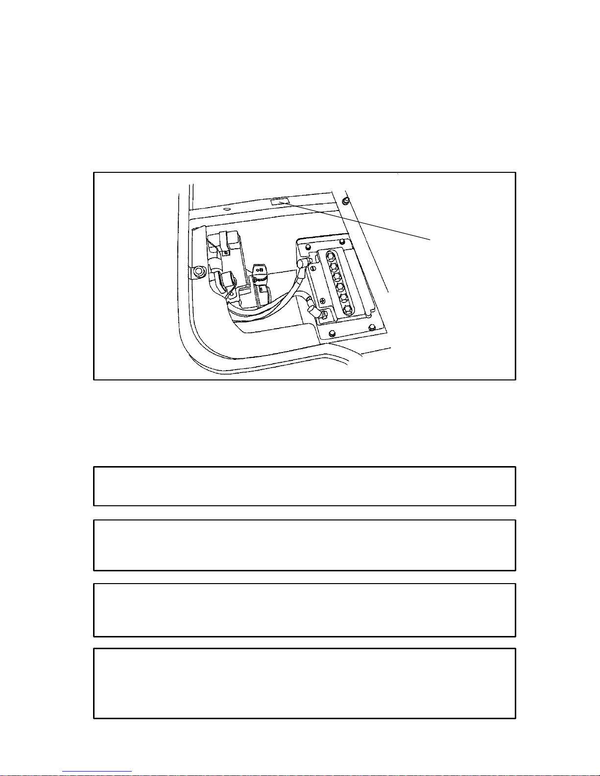
8. Disconnect the lower
oil delivery hose.
Remove the fitting (1)
from the oil tank.
Clean the fitting
screen. Reinstall the
fitting screen, torquing
to 14-17 ft. lbs.
Reattach the oil line.
Torque the banjo fitting
(2) to 14-17 ft. lbs.
9. Place shop towels
beneath the oil filter.
Using an oil filter
wrench, t urn t he filter
(3) counterclockwise to
remove.
10. Using a clean dry cloth,
clean the filter sealing
surface on the
crankcase.
11. Lubricate the o-ring on
the new filter with a
film of new engine oil.
Check to make sure the
o-ring is in good
condition. Also make
sure the o-ring from the
old filter is not still on
the engine.
12. Install the new filter (3) and tighten by hand 1/2 to 3/4 turn after
gasket contact.
13. Approximately one cup of engine oil will remain in the crankcase.
To drain, remove drain plug found on lower right side of
crankcase. NOTE: The sealing surfaces on the drain plug and
crankcase should be clean and free of burrs, nicks or scratches.
1
2
1
Page 66

64
MAINTENANCE AND LUBRICATION
Oil System
Oil and Filter Change (con t .)
14. Reinstall drain plug.
15. Remove dipstick and add two quarts (1.9 l.) of Polaris Premium 4
synthetic oil. Reinstall dipstick. NOTE: If sump is not drained,
add about 1 3/4 quarts initially.
16. Place gear selector in neutral and set parking brake.
17. Start engine and let it idle for one to two minutes. Stop engine and
inspect for leaks.
18. Re-check oil level on the dipstick and add oil as necessary to bring
the level to the upper mark on the dipstick.
19. Dispose of used filter and oil properly.
4 Cycle Premium 4 Synthetic Lubricant
Polaris Premium 4 All Season Synthetic engine oil has been specially
formulated for use in Polaris 4 cycle engines. It is a fully synthetic,
high performance, multi-viscosity oil designed to provide the ultimate
in lubrication performance and protection.
Premium 4 possesses unsurpassed film strength over the widest
possible temperature range. It resists viscosity and frictional
breakdown in ambient temperatures from -40° F. to 120° F. Its
exceptional frictional properties result i n more efficient operation, more
power output and lower fuel consumption.
Although Polaris Premium 4 is the only oil recommended for use in
this engine, use of any API certified “SH” oil is allowable. Oil may
need to be changed m ore frequently if Polaris Premium 4 is not used.
Follow the manufacturer’s recommendations for ambient temperature
operation.
Fuel Filter
Your Polaris UTV is equipped with an in-line fuel filter that should be
replaced by your dealer after every 100 hours of operation.
Do not attempt to clean these filters.
Page 67

1
65
MAINTENANCE AND LUBRICATION
Transmission Oil
The transmission lubricant level
should be checked at 25 hours or
monthly, whichever comes first.
Transmission oil should be changed
annually.
1. Position the vehicle on a level
surface.
2. Remove the fill plug (1), which
is located on the righthand side
of the machine.
3. Check the lubricant level.
Lubricant should be kept at the
bottom of the fill plug threads.
NOTE: We recommend the use of Polaris Premium Synthetic
Gearcase Lubricant for optimum performance.
CAUTION
Do not allow dirt or foreign materials to enter the transmission case.
Page 68

66
MAINTENANCE AND LUBRICATION
Front Gearcase
Gearcase Lubrication
The front gearcase lubricant level should be checked every six months
or 100 hours, whichever comes first. Front gearcase oil should be
changed annually as outlined in the Periodic Maintenance Schedule.
If the machine is used in wet conditions, the oil should be checked
more frequently.
If the oil has a milky appearance, it should be changed as soon as
possible.
Failure to properly maintain this important area can result in premature
wear or possible failure of the front grease components.
NOTE: We recommend the use of Polaris Premium Hub Oil for
optimum performance.
The front gearcase fill plug (1) is located on the right side of the front
gearcase.
1. With the UTV on a level
surface, remove fill plug and
check the lubricant level.
Lubricant should be kept at
the bottom thread of the fill
plug hole.
2. Support vehicle securely
with a jack stand.
3. Remove the front tire on the
driver’s side.
4. Remove fill plug.
5. Remove gearcase drain plug
(2) located on the bottom
right hand side and drain the
oil. Catch and discard used
oil properly.
6. Clean and reinstall the drain plug.
7. Add hub oil to the bottom thread of the fill plug hole.
8. Check for leaks.
1
2
Page 69

67
MAINTENANCE AND LUBRICATION
Cooling System
Operation
The overflow bottle (1) is
located in front of the right
front tire of the machine.
The coolant level must be
maintained between the
minimum and maximum
marks on the overflow
bottle.
The engine coolant level is
controlled or m aintained
by the recovery system.
The recovery system
components are the
overflow bottle, radiator
filler neck, radiator pressure cap and connecting hose.
As coolant operating temperature increases, the expanding (heated)
excess coolant is forced out of the radiator, past the pressure cap, and
into the overflow bottle. As engine coolant temperature decreases, the
contracting (cooled) coolant is drawn back up from the tank, past the
pressure cap, and into the radiator.
NOTE: Some coolant level drop on new machines is normal as the
system is purging itself of trapped air. Observe coolant levels and
maintain as recommended by adding coolant to the overflow bottle.
1
Page 70

68
MAINTENANCE AND LUBRICATION
Cooling System
Coolant Level Inspection
NOTE: Check the coolant
level when the engine is cold
(room or atmospheric
temperature).
1. Situate the vehicle on
level ground.
2. Check the coolant level
by looking at the
overflow bottle located in
front of the right front
wheel. The coolant level
should be between the
minimum mark (1) and
the maximum mark (2).
3. If the amount of coolant
is not within the operating
range, lift the hood and locate the overflow bottle lid. Remove the
lid and use a funnel to add coolant through the filler opening until
the fluid level has reached the maximum mark. Reinstall the cap.
NOTE: Polaris recommends the use of Polaris Premium 60/40
anti-freeze/coolant or a 50/50 mixture of high quality aluminum
compatible anti-freeze/coolant and distilled water. NOTE: Polaris
Premium 60/40 is already premixed and ready to use. Do not dilute
with water.
NOTE: Always follow the manufacturer’s mixing recommendations
for the freeze protection required in your area.
NOTE: In an emergency you can add water alone to the overflow
bottle, but it must be returned to the correct mixture ratio by adding
antifreeze concentrate as soon as possible.
1
2
CAUTION
If coolant must be added often, or if the overflow bottle runs
completely dry, there may be a leak in the system. Have the
cooling system inspected by your Polaris UTV dealer.
Page 71

69
MAINTENANCE AND LUBRICATION
Cooling System
Radiator Coolant Level Inspection
1. Lift the hood and locate the
radiator cap(1).
2. Visually inspect the level of
coolant in the radiator.
3. Using a funnel, slowly add
coolant if necessary.
NOTE: This procedure is only
required if t he cooling system has
been drained for maintenance
and/or repair. However, if the
overflow bottle has run dry, the
level in the radiator should be
inspected and coolant added if necessary.
NOTE: Use of a non-standard pressure cap will not allow the
recovery system to function properly. If the cap should need
replacement, contact your dealer for the correct replacement part.
Changing Coolant
To ensure that the coolant m aintains its ability to protect the engine,
the system be completely drained every two years, and a fresh mixture
of antifreeze and water should be added. Polaris recommends the use
of Polaris Premium 60/40 anti-freeze/coolant or a 50/50 mixture of
high quality aluminum compatible anti-freeze/coolant and distilled
water.
NOTE: Polaris Premium 60/40 is already premixed and ready to use.
Do not dilute with water.
NOTE: Always follow the manufacturer’s mixing recommendations
for the freeze protection required in your area.
Never remove the pressure cap when the engine is warm or hot.
Escaping steam can cause severe burns. The engine must be
cool before removing the pressure cap.
WARNING
1
Page 72

70
MAINTENANCE AND LUBRICATION
Cooling System
Radiator and Cooling Fan
Check and clean the screen and radiator fins for obstructions caused by
insects or mud as outlined in the Periodic Maintenance Schedule.
Do not obstruct or deflect air flow through the radiator by installing
unauthorized accessories in front of the radiator or behind the cooling
fan. Interference with the radiator air flow can lead to overheating and
consequent engine damage.
Coolant absorbs excessive heat from the engine and transfers it to the
air at the radiator. If the coolant level becomes low, the engine
overheats and may suffer damage. Check the coolant level each day
before operating the vehicle, and replenish coolant if the level is low.
Change the coolant as outlined in the Periodic Maintenance Schedule.
CAUTION
Using high-pressure water, as from a car wash facility, could
damage the radiator fins and impair the radiator’s effectiveness.
Page 73

71
MAINTENANCE AND LUBRICATION
Polaris Variable Transmission (PVT) System
The PVT system rotates at high speeds, creating large amounts
of force on clutch components. Extensive engineering and
testing have been conducted to ensure the safety of this product.
However, as the owner you have the following responsibilities to
make sure this system remains safe:
Do not modify any component of the PVT system. Doing so may
reduce its strength so that a failure may occur at high speeds.
This system has been precision balanced. Any modification will
cause the system to be out of balance, creating vibration and
additional loads on components.
Routine maintenance is the responsibility of the owner. Always
follow recommended maintenance procedures. See your dealer!
This PVT system is intended for use on Polaris products only.
The PVT housing must be securely in place during operation.
Failure to comply with this warning can result in severe injury or
death.
WARNING
PVT Drying
There may be some instances when water is accidently ingested into
the PVT system. Use the following instructions to dry it out before
operating.
1. Shift the transmission into neutral and apply full throttle for no
longer than 10 seconds and repeat as necessary. This will expel the
moisture and air dry the belt and clutches.
2. Allow the engine RPM to settle to idle speed, then shift the
transmission to the lowest available range.
3. Test for belt slippage. If the belt slips, repeat the process.
4. Take the vehicle to your dealer for service as soon as possible.
Page 74

72
MAINTENANCE AND LUBRICATION
Vehicle Immersion
If it’s impossible to take your UTV to a dealer before starting it, follow
the steps outlined below.
1. Move the vehicle to dry land, or at
the very least, to a water level below
the floor.
2. Disconnect the fuel pump wires.
3. Remove the spark plug.
4. Loosen the carburetor drain screw (1).
5. Turn the engine over several times
with electric start.
6. Dry the spark plug and reinstall, or
install a new plug.
7. Tighten the carburetor drain screw.
8. Reconnect the fuel pump wires.
9. Attempt to start the engine. If necessary, repeat the drying
procedure.
10. Take the machine t o your dealer for s ervice as soon as possible
whether you succeed in starting it or not.
NOTE: If water has been ingested into the PVT follow the procedure
on page 71 for drying.
If your vehicle becomes immersed, take it to your dealer before
starting the engine. Major engine damage can result if the
machine is not thoroughly inspected.
CAUTION
1
Page 75

73
MAINTENANCE AND LUBRICATION
Air Filter Service
We recommended that the air
filter be replaced annually.
When operating in extremely
dusty conditions, replacement
will be required more often.
1. Lift the box.
2. Remove the cover and
inspect the gasket. It
should adhere tightly to
the cover and seal all the
way around.
3. Remove the air filter. Do
not attempt to clean the
main element.
4. Install a new air filter.
NOTE: Apply a small
amount of general purpose
grease t o the sealing edges
of the filter before
installing.
5. Check the air box. If oil
or water deposits are
found, drain them into a
suitable container.
NOTE: Service more frequently if vehicle is operated in wet
conditions or at high throttle openings for extended periods.
Page 76

74
MAINTENANCE AND LUBRICATION
Breather Filter and Hoses
1. Lift the box and l ocate
the airbox (1).
2. Follow the righthand
breather line out of the
side of the airbox and
locate the filter (2).
3. Remove and inspect
the filter for debris.
Blow gently through
the filter in the
direction of the arrow
to check for clogging.
Replace as needed.
4. Check hoses for
cracks, deterioration,
abrasion, or leaks.
Replace as needed.
5. Reinstall the filter and clamps with the arrow pointing toward the
engine.
Do not perform this operation immediately after the engine has
been run. The exhaust system becomes very hot and can cause
severe burns.
WARNING
1
2
CAUTION
Operation of your vehicle without a breather filter can cause
engine damage.
Page 77

75
MAINTENANCE AND LUBRICATION
Spark Plugs
S Use NGK BKR5E spark plugs.
S Proper electrode gap is .036″ (.90 mm).
S Spark plug torque is 14 ft. lbs.(19 Nm).
Spark plug condition is indicative of engine operation. The spark plug
firing end condition should be read after the engine is warmed up and
the vehicle is driven at higher speeds. Immediately check the spark
plug for correct color.
Normal Plug
On a normal plug, the insulator tip is gray, tan or light brown. There
will be few combustion deposits, and the electrodes will not be burned
or eroded. This indicates the proper type and heat range for the engine
and the service.
NOTE: The tip should not be white. A white insulator tip indicates
overheating, caused by an improper spark plug or incorrect carburetion
adjustments.
Wet Fouled Plug
On a wet fouled plug, the insulator tip is black. A damp oil film
covers the firing end. There may be a carbon layer over the entire
nose. Generally, the electrodes are not worn. General causes of
fouling are excessive oil, improper use of the choke, or incorrect
carburetion adjustments.
Page 78

76
MAINTENANCE AND LUBRICATION
Spark Plug Removal and Replacement
1. Remove the seat to access the engine compartment.
2. Remove the spark plug cap.
3. Using the spark plug wrench provided in the tool kit, remove the
spark plug by rotating it counterclockwise.
4. Reverse the procedure for spark plug installation. Torque to 17 ft.
lbs. (2.3 kg/m).
Cylinder Head/Cylinder Base F asten er Torque
Have your dealer check the UTV cylinder head and cylinder base
fasteners for proper torque at the first service or after 25 hours.
The exhaust system or engine can cause serious burns.
Always wait for the engine to cool before removing spark plugs.
WARNING
CAUTION
Always use the spark plugs recommended in this Owner’s
Manual. Using the wrong plugs can cause engine damage.
Page 79

77
MAINTENANCE AND LUBRICATION
Spark Arrestor
The exhaust pipe must be periodically purged of accumulated carbon as
follows. Use the following procedure.
Do not perform this operation immediately after the engine has
been run. Exhaust system temperatures can reach 1000° F.
Because of the increased fire hazard, make sure there are no
combustible materials in the area when purging the spark arrestor.
Wear eye protection.
Do not stand behind or in front of the vehicle while purging the
carbon from the spark arrestor.
Never run the engine in an enclosed area. The exhaust contains
poisonous carbon monoxide gas.
Do not go under the machine while it is inclined.
Failure to heed these warnings could result in serious personal injury
or death.
WARNING
1. Remove the arrestor
clean-out plugs (1)
located on the bottom of
the muffler.
2. Place the transmission in
neutral and start the
engine. Purge
accumulated carbon from
the system by
momentarily revving the engine several times.
3. If some carbon is expelled, cover the exhaust outlet and rap on the
pipe around the clean-out plugs while revving the engine several
more times.
4. If particles are still suspected to be in the muffler, back the
machine onto an incline so the rear of the machine is one foot
higher than the front. Set the parking brake and block the wheels.
Make sure the machine is in neutral and repeat steps 2 and 3.
NOTE: See WARNING above.
1
Page 80

78
MAINTENANCE AND LUBRICATION
Spark Arrestor (cont.)
5. If particles are still suspected to be in the muffler, drive the
machine onto the incline so the front of the machine is one foot
higher than the rear. Set the parking brake and block the wheels.
Make sure the machine is in neutral and repeat steps 2 and 3.
NOTE: See WARNING above.
6. Repeat steps 2 through 5 until no more particles are expelled when
the engine is revved.
7. Stop the engine and allow the arrestor to cool.
8. Reinstall the arrestor plugs.
Page 81

79
MAINTENANCE AND LUBRICATION
Throttle Pedal
Throttle Freeplay
If the throttle pedal (1) has
excessive play due to cable
stretch or cable misadjustment,
it will cause a delay in throttle
response, especially at low
engine speed. The throttle may
also not open fully. If the
throttle pedal has no play, the
throttle may be hard to control,
and the idle speed may be
erratic. Check the throttle
pedal play periodically as
outlined in the Periodic
Maintenance Schedule. Adjust
the play if necessary.
Throttle Fr eeplay Inspection
1. Apply the parking brake (2).
2. Put the gear shift lever in the neutral position.
3. Start the engine and warm it up thoroughly.
4. Measure the distance the throttle pedal moves before the engine
begins to pick up speed. Freeplay should be 1/16 to 1/8 inches.
Adjustment
1. Slide the boots (1) off the inline cable adjuster sleeve (2). Loosen
the adjuster locknut (3).
2. Turn the adjuster until 1/16 to 1/8 inch freeplay is achieved.
NOTE: While adjusting freeplay, you must flip the throttle lever back
and forth.
3. Tighten the locknut and slide the boots over the cable adjuster until
they touch at the midpoint of adjuster.
1
2
11
2
3
Page 82

80
MAINTENANCE AND LUBRICATION
Carburetor/Engine Idle RPM Adjustment
The idle speed adjustment should be performed as outlined in the
Periodic Maintenance Schedule, or whenever the idle speed is changed.
Recommended engine idle RPM is 1200 +/- 200. If the engine idle
speed is not satisfactory, and all other conditions are favorable, the
carburetor can be adjusted with the following procedure.
1. Apply the parking brake.
2. Place the gear shift lever in the
neutral position.
3. Warm up the engine by
running the vehicle
approximately five minutes.
4. Remove the the seat and locate
theidlescrew(1).
5. Place the transmission in gear
(with the parking brake
applied.)
6. Adjust the carburetor idle
screw in or out until the
desired idle RPM is reached.
Turn the screw in (clockwise)
to raise RPM. Turn the screw
out (counterclockwise) to
lower RPM.
1
Page 83

81
MAINTENANCE AND LUBRICATION
Brakes
Front and Rear Brake In sp ectio n
The front and rear brakes are
hydraulic disc type brakes and are
activated by the brake pedal. See
page 43.
Routine inspections are recommended
to keep the brake system in good
operating condition. Inspect the level
of the brake fluid before each
operation.
Change the brake fluid as outlined in
the Periodic Maintenance Schedule.
The brake fluid should also be
changed if it becomes contaminated
with dirt or water.
Inspection Procedure:
1. Position the vehicle on level ground.
2. Inspect the brake fluid by looking at the reservoir (1) under the
hood. The level should be between the upper (MAX) and lower
(MIN) level lines.
3. If the fluid level is lower than the lower level line, add brake fluid
to the upper (MAX) line.
4. Apply the brake forcefully for a few seconds and check for fluid
leakage around the fittings.
1
CAUTION
Change the fluid in the brake system completely if the fluid level is
below the minimum, or if the type and brand of the fluid already in
the reservoir are unknown.
Once a bottle of brake fluid is opened, use what is necessary and
discard the rest. Do not store or use a partial bottle of brake fluid.
Brake fluid is hygroscopic, meaning it rapidly absorbs moisture
from the air. This causes the boiling temperature of the brake fluid
to drop, which can lead to early brake fade and the possibility of
serious injury.
Page 84

82
MAINTENANCE AND LUBRICATION
Brakes
Front and Rear Brake In sp ectio n
Check brake system for fluid leaks.
Check brake for excessive travel or
spongy feel.
Check friction pads for wear, damage and
looseness.
Inspect the brake disc spline and pad wear
surface for excessive wear.
Change pads when worn to 3/64″ (.1 cm),
about the thickness of a dime.
Brake Lig ht Insp ectio n
When the brake pedal is depressed, the console brake light comes on.
Check the brake light before each ride.
1. Turn the ignition switch to the ON position.
2. Depress the brake pedal. The brake light should come on after
about 10mm (0.4 in.) of pedal travel. If the light doesn’t come on,
check the bulb.
3/64″ (.1 cm)
If the brake pedal has a “spongy” feeling when applied, there
may be air in the brake lines, or the brake may be defective. Do
not operate the vehicle under these conditions. Have the brake
system serviced by an authorized Polaris dealer immediately.
WARNING
Headlight and taillight lenses may become dirty. Wash frequently
to maintain lighting quality. Poor lighting while operating can result
in severe injury or death.
WARNING
CAUTION
Do not service while lights are hot. Serious burns may result.
Page 85

83
MAINTENANCE AND LUBRICATION
Brakes
Parking Brake Inspectio n
1. Slowly push the parking brake
down with your foot.
2. After 8 to 12 clicks of lever
travel, check the vehicle for
movement. The vehicle should
not roll while parked. If the
vehicle moves, adjustment is
necessary
Parking Brake Adjustment
1. Place the vehicle in neutral on a
flat level surface.
2. Carefully lift the rear of the vehicle off the ground and stabilize on
jack stands.
3. Loosen the locknut on the rear caliper adjustment bolt.
4. Tighten the adjustment bolt until the rear tire will not rotate.
5. Back the adjustment bolt out 1/4 turn.
6. Tighten the jam nut while holding the adjustment nut in place.
7. Repeat this procedure on t he other rear tire.
1
Page 86

84
MAINTENANCE AND LUBRICATION
Steering Wheel Inspection
Check the steering wheel for specified freeplay and smooth operation
as outlined in the Periodic Maintenance Schedule.
1. Park the vehicle on level ground.
2. Lightly turn the steering wheel left and right.
3. There should be 0.8 - 1.0 in (20 - 25 mm) of free play.
4. If there is excessive freeplay or strange noises, or the steering feels
rough or “catchy,” have the steering system inspected by an
authorized Polaris dealer.
Rear Spring Adjustment
The rear shock absorber springs
are adjusted by rotating the
adjustment cam (1) i n the
direction required to increase or
decrease spring tension.
1
Page 87

85
MAINTENANCE AND LUBRICATION
Seat Belts
Inspect all three seat belts for proper operation before each use of the
vehicle.
1. Push the latch plate into the buckle until it clicks. The latch plate
must slide smoothly into the buckle. A click indicates that it’s
securely latched.
2. Push the red button in the middle of the buckle to make sure it
releases freely .
3. Check the belt webbing for wear, cuts or damage. If any
irregularities are found, have the seat belt system checked and/or
replaced by an authorized Polaris dealer.
The UTV seat belt is adjustable
and should be adjusted for both
the operator and passenger
before driving. Although
having the belt at 30° is typical
for many people, it will not
accommodate all body sizes
and shapes. Make sure the
seat belt is adjusted to the
lowest possible lap position
before riding.
1. To adjust, loosen the bolts
(1).
2. Reposition both the buckle
and retractor. Tighten
bolts.
NOTE: The center belt does not self adjust. Before riding, pull on the
strap to secure the belt on the lap of the center passenger.
1
Riding as a passenger in this vehicle is not safe for anyone under
the age of five. Do not allow anyone under five to ride as a
passenger. Serious injury or death could result.
WARNING
Page 88

86
MAINTENANCE AND LUBRICATION
Tires
Tire Tread Depth
Always replace tires when
tread depth i s worn to 1/8″
(.3 cm) or less.
Axle and Wheel Nut Torque Specifications
Inspect the following items occasionally for tightness, and if they’ve
been loosened for maintenance service.
Front Spindle Nut(s) Dealer Performed Service
Front Wheel Nuts 35 ft. lbs.
Center and Rear Hub
Retaining Nut(s)
120 ft. lbs.
Rear Wheel Nuts 35 ft. lbs.
Operating your vehicle with worn tires will increase the possibility of
skidding, loss of control, and an accident.
Always replace tires when the tread depth measures 1/8″ (.3 cm) or
less.
WARNING
CAUTION
Always maintain proper tire pressure. Improper tire inflation may
affect vehicle maneuverability.
When replacing tires, always use original equipment size and
type. The use of non-standard size or type tires may adversely
affect vehicle handling.
1/8I (.3 cm)
Page 89

87
MAINTENANCE AND LUBRICATION
Wheels
Wheel Removal
1. Stop the engine, place the transmission in gear and lock the
parking brake.
2. Loosen the wheel nuts slightly.
3. Elevate the side of the vehicle by placing a suitable stand under the
frame.
4. Remove the wheel nuts and washers. Remove the wheel.
Wheel Installation
1. With the transmission in
gear and the parking brake
locked, place the wheel in
the correct position on the
wheel hub. Be sure the
valve stem is toward the
outside and rotation arrows
on the tire point toward
forward rotation.
2. Attach the wheel nuts and
washers and finger tighten.
3. Carefully lower the vehicle t o the ground.
4. Torque the wheel nuts according to the specifications on page 86.
CAUTION
If wheels are improperly installed, you may experience an adverse
effect on vehicle handling and/or tire wear. Both could lead to loss
of control, overturn, and injury.
Page 90

88
MAINTENANCE AND LUBRICATION
Lights
Headlight Beam Adjustment
1. Place the vehicle on a
level surface with the
headlight approximately
25 ft. (7.6 m) from a
wall.
2. Measure the distance
from the floor to the
center of the headlight
and make a mark on the
wall at the same height.
3. Start the engine and
switch on the headlight.
4. Observe the headlight
aim. The most intense
part of the headlight beam should be aimed 8″ (20.3 cm) below
the mark placed on the wall in step 2. NOTE: Include the weight
of a rider on the seat while performing this step.
5. Adjust beam to desired position by turning adjustment screws (1)
in headlight cover as follows:
Turn the right screw clockwise to adjust to the left.
Turn the left screw clockwise to adjust to the right.
Turn the bottom s crew clockwise to adjust upward.
1
1
Page 91

89
MAINTENANCE AND LUBRICATION
Lights
Indicator Lamp Replacement
1. Lift the hood.
2. Reach in behind the dash panel
and lift the release (1) to
unplug the light from the
harness.
3. Using a flathead screwdriver,
press on the tab (2) on the top
of the light to remove the
indicator light assembly from
the dash panel.
4. Using a screwdriver, turn the
light that needs to be replaced
1/4 turn counterclockwise.
5. Grip the light with a needle nose plier and remove the light from
the assembly.
6. Install the new light and use a small flat head screwdriver to seat it
into place, 1/4 turn clockwise.
7. Snap the assembly back into the dash panel and reconnect the
harness.
8. Close the hood.
Tool Kit
To help you perform routine maintenance, a tool kit is provided with
your vehicle. Items included in the kit are:
S A screwdriver
S An open-end wrench (8-10 mm)
S An open-end wrench (12-14 mm)
S A tire pressure gauge
S A spark plug wrench and handle
NOTE: Additional tools will be necessary to perform routine
maintenance.
1
2
Page 92

90
MAINTENANCE AND LUBRICATION
Cleaning Your UTV
Keeping your vehicle clean will not only improve its appearance but it
can also extend the life of various components. With a few
precautions, your vehicle can be cleaned much like an automobile.
The best and safest way to clean your vehicle is with a garden hose and
a pail of mild soap and water. Use a professional type washing mitten,
cleaning the upper body first and the lower parts last. R inse with water
frequently and dry with a chamois to prevent water spots. NOTE: If
warning labels are damaged, contact your Polaris dealer for free
replacement.
If a high pressure type car wash system is used, extreme care must be
taken to avoid water damage to the wheel bearings, transmission seals,
body panels, brakes, headlights and warning labels. Many expensive
repair bills can result from using high pressure detergent systems.
NOTE: If a high pressure car wash is used, grease all zerk fittings
immediately after washing. Also run the vehicle to evaporate any
water that may have entered the engine or exhaust system.
Page 93

91
MAINTENANCE AND LUBRICATION
Storage
If your vehicle is to be placed in extended or off season storage, the
following steps should be taken to preserve its condition.
1. Perform all necessary repairs and thoroughly clean the vehicle.
2. Remove the spark plug and pour approximately one ounce of
Premium 4 oil into the cylinder. Operate the starter for a few
seconds and reinstall the spark plug.
3. Remove the battery. Store it in a cool, dry place out of the sun.
4. Lubricate s uspension pivot points, lower steering post and rear axle
fittings.
5. Drain the engine side cover.
6. Block the vehicle so all tires are suspended off the ground.
7. Spray oil on all unpainted metal surfaces to prevent rusting. Avoid
getting oil on rubber parts or in the brakes.
8. Lubricate all cables.
9. Tie a plastic bag over the exhaust pipe and air cleaner inlet to
prevent moisture or small animals from entering.
10. Cover the vehicle with a canvas cover. Do not use plastic or coated
materials since they do not allow ventilation for the vehicle.
Page 94

92
MAINTENANCE AND LUBRICATION
Removal from Storage:
1. Check the battery electrolyte level and charge the battery if
necessary. Install it in the vehicle. Make sure the battery vent hose
is routed properly and that it’s not pinched or restricted in any way.
2. Make sure the spark plug is tight.
3. Fill the fuel tank with fuel.
4. Check all the points listed in the Daily Pre-Operation Inspection
section beginning on page 47.
NOTE: Tightness of the bolts, nuts and other fasteners should be
checked by an authorized Polaris dealer.
5. Lubricate as outlined in the Periodic Maintenance Schedule.
Do not run the engine in a closed area. Exhaust gases contain
carbon monoxide; a colorless, odorless, poisonous gas.
Breathing exhaust gas leads to carbon monoxide poisoning,
asphyxiation and death.
WARNING
Page 95

93
MAINTENANCE AND LUBRICATION
Battery
Replenishing Battery Fluid
A poorly maintained battery will
deteriorate rapidly. Check the battery
fluid level often. The fluid level
should be kept between the upper and
lower level marks (1).
Battery Connections
Battery terminals and connections should be kept free of corrosion.
If cleaning is necessary, remove the corrosion with a stiff wire brush.
Wash with a solution of one tablespoon baking soda and one cup water.
Rinse well with tap water and dry off with clean shop towels. Coat the
terminals with dielectric grease or petroleum jelly.
CAUTION
Whenever removing the battery, always disconnect the negative
(black) cable first. When reinstalling the battery, always connect
the negative (black) cable last.
1
CAUTION
Use only distilled water when refilling a battery. Tap water
contains minerals that are harmful to a battery.
Allowing cleaning solution or tap water to enter the battery will
shorten the life of the battery.
CAUTION
Vehicle lamps may burn out if the battery is disconnected during
vehicle operation. The reverse speed limiter may also be damaged.
Page 96

94
MAINTENANCE AND LUBRICATION
Battery
Battery Removal
1. Remove the seat to
access the battery.
2. Remove the battery
vent tube from the
battery.
3. Disconnect the black
(negative) battery cable
first.
4. Disconnect the red
(positive) battery cable
next.
5. Lift the battery out of
the vehicle, being
careful not to tip it
sideways and spill any
electrolyte.
Battery electrolyte is poisonous. It contains sulfuric acid.
Serious burns can result from contact with skin, eyes or
clothing. Antidote:
External: Flush with water.
Internal: Drink large quantities of water or milk. Follow with
milk of magnesia, beaten egg, or vegetable oil. Call physician
immediately.
Eyes: Flush with water for 15 minutes and get prompt medical
attention.
Batteries produce explosive gases. Keep sparks, flame,
cigarettes, etc. away. Ventilate when charging or using in an
enclosed space. Always shield eyes when working near
batteries. KEEP OUT OF REACH OF CHILDREN.
WARNING
Page 97

95
MAINTENANCE AND LUBRICATION
Battery
Battery In stallation
1. Set the battery in its holder.
2. Install the battery vent tube. It must be free from obstructions and
securely installed. If not, battery gases could accumulate and cause
an explosion. The tube should be routed away from the frame and
body to prevent corrosion. Avoid skin contact with electrolyte as
severe burns could result.
3. First connect and tighten the red (positive) cable.
4. Second connect and tighten the black (negative) cable.
5. Verify that cables are properly routed.
NOTE: When your UTV is placed in storage for three months or
more, the battery should be removed, charged to proper level, and
stored in a cool dry place. Before reusing, take the battery to your
dealer for testing and recharging.
CAUTION
If electrolyte spills, immediately wash it off with a solution of one
tablespoon baking soda and one cup water to prevent damage to
the UTV.
To avoid the possibility of explosion, always connect battery
cables in the order specified. Red (positive) cable first; black
(negative) cable last.
WARNING
Page 98

96
SPECIFICATIONS
UTV2X4 UTV4X4
Gross Vehicle Weight 2500 lbs. 2700 lbs.
Fuel Capacity 8.0 Gallons 8.0 Gallons
Towing Capacity 1400 lbs. 1500 lbs.
Maximum Cargo Box Load 850 lbs. 1000 lbs.
Overall Length 113 in. 113 in.
Overall Width 58 in (tires) 60 in (box) 58 in (tires) 60 in (box)
Overall Height 74 in. 75 in.
Wheelbase 76 in. 76 in.
Ground Clearance 5.8 in. 7in.
Dry Weight 1196 lbs. 1263 lbs.
Cargo Box (L x W x H) 58 x 46 x 10 in. 58 x 46 x 10 in.
Minimum Turning Radius 132 in. 132 in.
Engine Oil Capacity 2qts. 2qts.
Coolant Capacity 2.25 qts. 2.25 qts.
Engine 4valve4strokesingle
cylinder with counter
balance
4valve4strokesingle
cylinder with counter
balance
Displacement 425 cc 499 cc
Bore x Stroke 87.9 x 70 92 x 75
Pilot Jet 42.5 42.5
Main Jet 135 142.5
Needle Jet P-6 (829) P-6 (829)
Jet Needle 4LC38-3 4MB32-3
Air Screw 21/4 21/2
Alternator Output 250 W 250 W
Compression Ratio 9.2 10.2:1
Starting System Electric Electric
Carburetor 34 mm - CV Mikuni 34 mm - CV Mikuni
Ignition System CDI CDI
Ignition Timing 30_ @ 5000 rpm 30_ @ 5000 rpm
Spark Plug NGK BKR5E NGK BKR5E
Page 99

97
SPECIFICATIONS
UTV2X4 UTV4X4
Lubrication System Dry Sump Dry Sump
Engine Oil 0W/40 0W/40
Driving System Type PVT PVT
Shift Type Single Lever on dash Single Lever on dash
Gear Reduction - Low 8.6:1 8.6:1
Gear Reduction - Reverse 5.9:1 5.9:1
Gear Reduction - High 4.6:1 4.6:1
Drive Ratio - Front: NA 3.83:1
Drive Ratio - Final 3.70:1 3.70:1
Tire Size - Front 23 x 8.5 - 12 (Turf) 25 x 10 - 12
Tire Size - Rear 23 x 10 - 12 (Turf) 25 x 11 - 12
Tire Pressure - Front 10 psi 10 psi
Tire Pressure - Rear 10 psi 10 psi
Brake Foot Activated, 4 Foot Activated, 4
BrakeFootActivated,
4
wheel hydraulic disc
FootActivated,4
wheel hydraulic disc
Front Hydraulic disk, float-
ing caliper
Hydraulic disk, floating caliper
Rear Hydraulic disk, float-
ing caliper with me-
chanical parking
brake
Hydraulic disk, floating caliper with mechanical parking
brake
Parking Brake Foot activated
mechanical
Foot activated
mechanical
mechanicalmechanica
l
Hood Headlight (watts) 2 dual beam - 35W -
quartz / halogen
2 dual beam - 35W -
quartz / halogen
Taillights (watts) 2 single beam, 5W 2 single beam, 5W
Brake Light (watts) 2 single beam, 5W 2 single beam, 5W
Indicator Light (watts) 1.0 1.0
Page 100

98
TROUBLESHOOTING
ENGINE CRANKS BUT FAILS TO START
No Fuel Water in Fuel Spark Plug
Drain System
No Spark to
Spark Plug
Contact Your
Dealer
ENGINE STOPS OR LOSES POWER
No Fuel
Contact Your
Dealer
Contact Your
Dealer
Overuse of
Choke
Spark Plug
Fouled
Engine
Overheated
Clean Engine
Exterior
Water in Fuel
Air Filter
Clogged
Fuel Vent Line
Kinked or
Plugged
Clean Radiator
screen
Fuel Pump
Faulty
Contact Your
Dealer
Plugged fuel
line or fuel
filter
 Loading...