

Page 1

2003 SNOWMOBILES
Universal Owner's Maintenance
and Safety Manual
Page 2

Read, understand, and follow all of the instructions
and safety precautions in this manual and on all
product labels.
Failure to follow the safety precautions could result
in serious injury or death.
PROPOSITION 65
WARNING
Snowmobile engines discharge fuel
and exhaust, which contain chemicals
known to the State of California to
cause cancer and birth defects or other
reproductive harm, onto the snow on
which they operate. Keep this engine
properly tuned and avoid unnecessary
idling and spillage during fueling.
WARNING
The engine exhaust from this
product contains chemicals known
to cause cancer, birth defects or
other reproductive harm.
Page 3

What’s the hottest thing on snow?
Our new web site. It’s designed just for YOU!
S Technical tips
S New product introductions
S Event schedules
S Parts and Service Manual information
S Exciting details about The Way Out
Check it out...
www.polarisindustries.com/owner
1
Page 4

-NOTES-
2
Page 5

WELCOME
Thank you for purchasing a Polaris snowmobile, and welcome to our
world-wide family of Polaris enthusiasts. Polaris proudly produces an
exciting line of recreational products, including snowmobiles,
all-terrain vehicles, personal watercraft, utility vehicles, and Victory
motorcycles.
We believe Polaris sets the standard of excellence for all snowmobiles
manufactured in the world today. Many years of experience in
engineering, design, and development have gone into making your
Polaris snowmobile the finest machine we’ve ever produced.
Follow the instructions and recommendations in this Owner’s Manual
for safe and enjoyable operation of your vehicle. Your Owner’s Manual
contains instructions for minor maintenance, but major repairs are
covered in the Polaris Service Manual and should be performed by a
Factory Certified MSD (Master Service Dealer) Technician.
Your Polaris snowmobile dealer knows your vehicle best and is
interested in your complete satisfaction. Return to your dealership for
all of your service needs during, and after, the warranty period.
Polaris also takes great pride in our PAA (Parts Apparel and
Accessories) which are available on our online store
www.purepolaris.com. Have your accessories and clothing delivered
right to your door!
Polaris and Polaris The Way Out are registered trademarks of P olaris
Industries Inc.
Copyright 2001
Polaris Industries Inc.
All Rights Reserved Printed in the U.S.A.
3
Page 6

TABLE OF CONTENTS
Section 1 - Introduction 5 - 9..................
This section contains helpful information for owners and drivers and
illustrates the location of important identification numbers that should
be recorded in your Owner’s Manual.
Section 2 - Safety 1 1 - 33.....................
This section describes safe vehicle operation and identifies warning
decals and their locations.
Section 3 - Features and Controls 36 - 41......
This section illustrates the locations of your snowmobile’s controls and
features.
Section 4 - The Perfect Fit 43 - 74..............
This section explains how to tailor the suspension and other features
for an optimum riding experience.
Section 5 - Getting Ready to Ride 75 - 81.......
This section explains procedures that must be performed before riding.
Section 6 - Operation 83 - 103.................
This section explains proper engine break-in, operation of features, and
operating procedures.
Section 7 - Maintenance 105 - 165.............
This section defines your role, and your dealer’s role, in your
snowmobile’s regular maintenance.
Section 8 - Troubleshooting 167 - 175..........
This section is a quick reference guide to solving problems.
Section 9 - Warranty 178 - 183.................
This section contains specific warranty information.
4
Page 7

SECTION 1 - INTRODUCTION
Important Notes for Drivers 6.................
Preservation Of The Environment 7 - 8........
Vehicle Identification Numbers 9..............
Section 1 contains helpful information for owners and drivers and
illustrates the location of important identification numbers that should
be recorded in your Owner’s Manual. It also defines your role in
protecting and respecting your environment while experiencing The
Way Out.
5
Page 8

INTRODUCTION
Important Notes For Owners And Drivers
n After reading this manual, store it in the snowmobile for
convenient reference. It should remain with the snowmobile when
sold.
n This manual contains the latest information at the time of printing.
We reserve the right to make product changes and improvements
without notice.
n The illustrations and photos used in this manual are general
representations. Your model may differ.
n Follow the maintenance program outlined in this manual.
Preventive maintenance ensures that critical components of the
snowmobile are inspected by your dealer at specific mileage
intervals.
n You and your dealer must complete the registration form included
with your snowmobile and forward it to us. This completed
form is necessary to ensure warranty coverage.
n Protect and preserve your right to ride by joining your local trail
riding clubs.
6
Page 9

INTRODUCTION
Preservation Of The Environment
Please operate your snowmobile with consideration for the protection
and preservation of our environment.
Noise Level
One of the most publicized issues about snowmobiles is noise. The
Society of Automotive Engineers (SAE), the standard-setting body for
snowmobile development, recommends that snowmobiles conform to
prescribed sound levels.
Polaris snowmobiles are engineered to conform t o these SAE
standards. Our muffler systems are designed to reduce noise levels and
must not be altered or removed. The sound of your snowmobile may
not be welcome to non-snowmobilers, so you have a responsibility to
operate your snowmobile with concern for others. We do our part by
manufacturing quieter machines; we ask your help to further reduce the
impact of noise by operating your snowmobile safely and responsibly.
Air Pollution
Polaris engineers continuously investigate ways to reduce emission
levels of two-stroke engines. We expect our efforts to lead to the
reduction of potential air pollution.
In addition to our technological research, we encourage government
agencies, manufacturers, distributors, dealers, ecologists, and other
interested parties to work together to develop data on environmental
topics.
7
Page 10

INTRODUCTION
Preservation Of The Environment
Polaris is committed to supporting an environmental education
campaign. We encourage state and provincial governments across the
snowbelt to adopt rigorous safety training programs t hat encourage
protection of our environment, including wildlife and vegetation.
Snowmobile clubs and other organizations are working together to
protect our environment. Please support their efforts and do your part
to preserve and protect our environment.
Respect your snowmobile;
respect your environment;
and you will earn
the respect of everyone.
8
Page 11

INTRODUCTION
Vehicle Identification Numbers
Please record your snowmobile identification numbers below for future
reference:
Tunnel VIN (lower right side of the tunnel)
Engine Serial Number (right front side of engine crankcase)
Remove the spare key and store it in a safe place. Your key can be
duplicated only by obtaining a key blank from Polaris and mating it
with your existing key.
The VIN and engine serial numbers are necessary for model
identification when registering your vehicle and obtaining insurance,
or when replacement parts are required. If your snowmobile is stolen,
these numbers are essential to its recovery and identification.
Dealer Imprint
9
Page 12

-NOTES-
10
Page 13

SECTION 2 - SAFETY
Operator Safety 12 - 27.......................
Safety Decals and Locations 28 - 33...........
Section 2 describes safe vehicle operation and identifies warning decals
and their locations.
11
Page 14
SAFETY
Operator Safety
The following two pages identify signal words and symbols that appear
in this manual. Your safety is involved when these words and symbols
are used. Become familiar with their m eanings before reading the
manual.
The safety alert symbol, on your snowmobile or in this manual,
alerts you to the potential for personal injury.
WARNING
Indicates a potential hazard that could result in serious injury or
death.
CAUTION
Indicates a potential hazard that may result in minor personal
injury or damage to the machine.
CAUTION
Indicates a situation that may result in damage to the machine.
NOTE
“NOTE:” will alert you to important information or instructions.
12
Page 15

SAFETY
Operator Safety
WARNING
Driving a snowmobile requires your full attention. DO NOT drink
alcohol or use drugs or medications before or while driving. They will
reduce your alertness and slow your reaction time. In most states and
provinces, it’s prohibited by law to drive while intoxicated or under the
influence of drugs.
Polaris produces high performance snowmobiles capable of traveling at
high speeds. Extra caution must be observed to ensure operator safety.
Make sure your snowmobile is in excellent operating condition at all
times. We strongly recommend that the operator check major and vital
safety components before every ride.
All Polaris snowmobiles are designed and tested to provide safe
operation when used as directed. Failure of critical machine
components may result from operation with any modifications,
especially those that increase speed or power. DO NOT MODIFY
YOUR MACHINE. The snowmobile may become aerodynamically
unstable at speeds higher than those for which it is designed. Loss of
control may occur at higher speeds. Modifications may also create a
safety hazard and lead to bodily injury.
The warranty on your entire machine is terminated if any equipment
has been added, or any modifications have been made, to increase the
speed or power of the snowmobile.
13
Page 16
SAFETY
Operator Safety
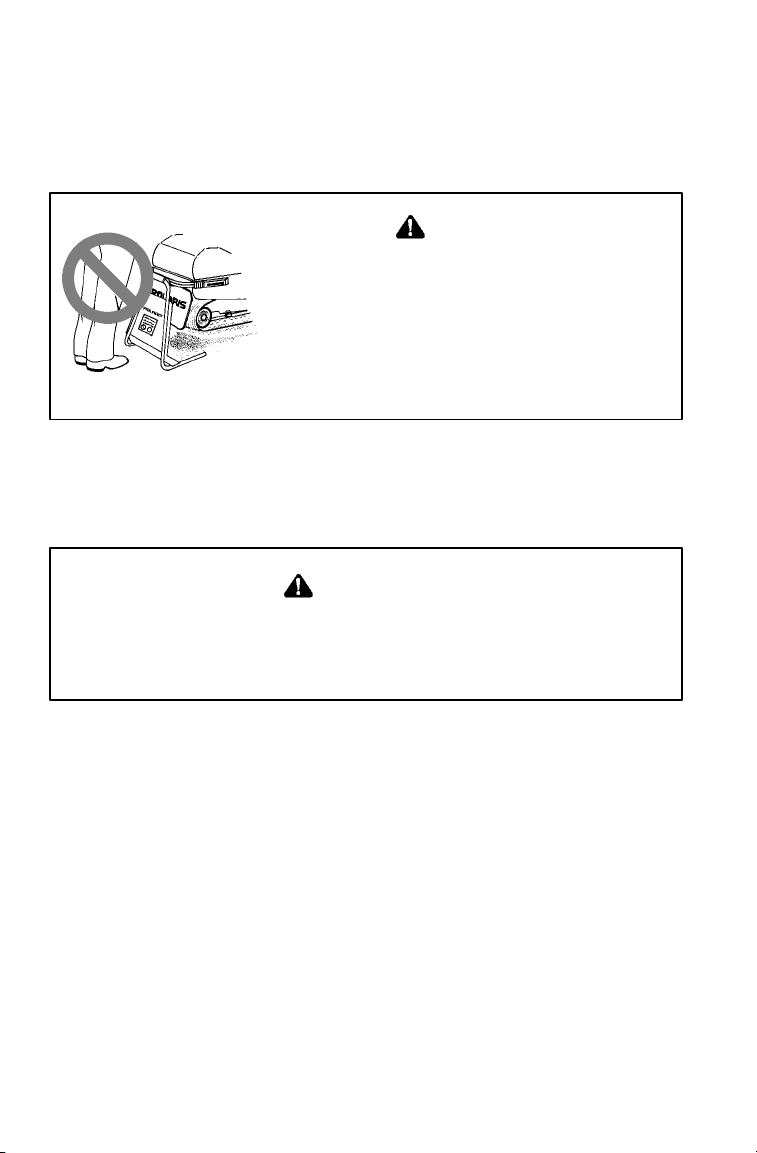
Stay Away From Moving Parts
WARNING
Never hold the snowmobile up or stand
behind it while warming up the track. A
loose track or flying debris could cause
serious personal injury or death.
We recommend having your dealer perform
track service and alignment procedures.
Be alert when riding, and remain properly seated to stay clear of the
track. Your snowmobile is propelled by a revolving track that must be
partially exposed for proper operation. Serious injuries may result if
hands, feet, or clothing become entangled in the track.
WARNING
Stop the engine before attempting adjustments. If contact is
made with fingers or clothing, the moving parts of an engine
can cause serious injury.
Never attempt adjustments with the engine running. Turn off the
ignition, raise the hood, make the adjustment, secure shields and
guards, secure the hood, and then restart the engine to check its
operation.
14
Page 17
SAFETY
Operator Safety
Be Seated and in Position to Control the Vehicle
WARNING
Improper riding position may seriously reduce your ability to
control the machine and may result in serious injury or death.
Always be properly seated and in position to control your vehicle.
Operating a snowmobile requires skill and balance for proper control.
Rider positions may vary from person to person as each becomes more
skilled; but under most conditions, the proper position is to be seated
with feet on the running boards, and comfortably positioned for proper
throttle, brake, and steering control.
WARNING
Use of a backrest may hinder your weight shifting ability. This
could affect your ability to control this rider-active vehicle in
certain extreme driving situations.
Be Prepared fo r the Unexpected
For your safety, always ride in a group of other snowmobilers. Always
tell someone where you’re going and how long you expect to be gone.
If it isn’t possible to ride with others, and you must travel into remote
areas, always carry survival equipment that’s appropriate to the
conditions you may encounter. Such equipment may include, but is
not limited to: extra clothing, a sleeping bag, a flashlight, food and
water, a signaling mirror, a means of building a fire, and a two-way
radio or cellular t elephone.
15
Page 18
SAFETY
Operator Safety
Do Not Overload Cargo Carrier
Too much weight on the rear of the machine may reduce your ability to
steer. Do not exceed carrier and rack weight limits, and do not allow a
passenger to sit on the seat back or the cargo carrier.
WARNING
Control becomes more difficult with two people on board. More
space is required to make turns, and longer distances are needed
for stopping. Make sure the passenger remains seated behind the
driver, facing forward, with both feet placed firmly on the running
boards. Slow down and avoid “jumping” your snowmobile.
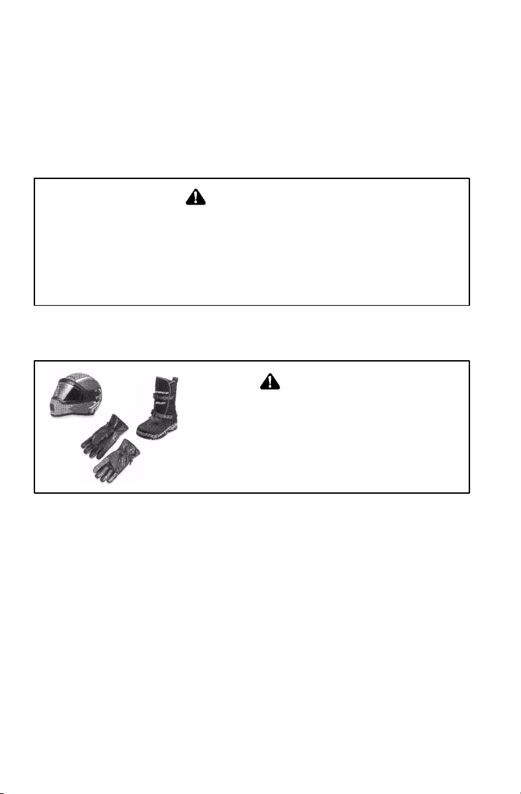
Always Wear Clothing Designed f or Snowmobiling
WARNING
Loose clothing or long scarves may
easily become entangled in moving
parts and cause serious personal injury .
Always wear an approved helmet and
eye protection.
Be aware of the weather forecast and especially the wind chill. A table
is provided on page 26 for your reference. To better enjoy your ride,
be prepared, warm, and comfortable.
16
Page 19
SAFETY
Operator Safety
Disabled Operators
Safe operation of this rider-active vehicle requires good judgement and
physical skills. Operators with cognitive or physical disabilities have
an increased risk of loss of control, which could result i n serious injury
or death.
Know the Limitations of the Machine
and Yo ur Skills as a Driver
WARNING
High speed driving, especially at night, is dangerous and unwise
and could result in serious personal injury or death.
Observe all state and local laws governing snowmobile operation.
They’ve been established for your protection.
Always be alert and pay attention to the trail ahead of you.
Multiplying speed (MPH) by 1.5 will equal the approximate number of
feet per second your machine travels. If your speed is 40 MPH, your
machine is traveling about 60 feet per second. If you look back for
only two seconds, your machine will travel about 120 feet. If your
speed is 60 MPH, your machine will travel about 180 feet in two
seconds.
Traveling at night requires extra caution. Check headlight and taillight
to ensure proper operation, and don’t “over drive” your headlight
beam. Always be able to bring your machine to a stop in the distance
illuminated by the headlight.
17
Page 20
SAFETY
Operator Safety
Know the Limitations of the Machine
and Yo ur Skills as a Driver
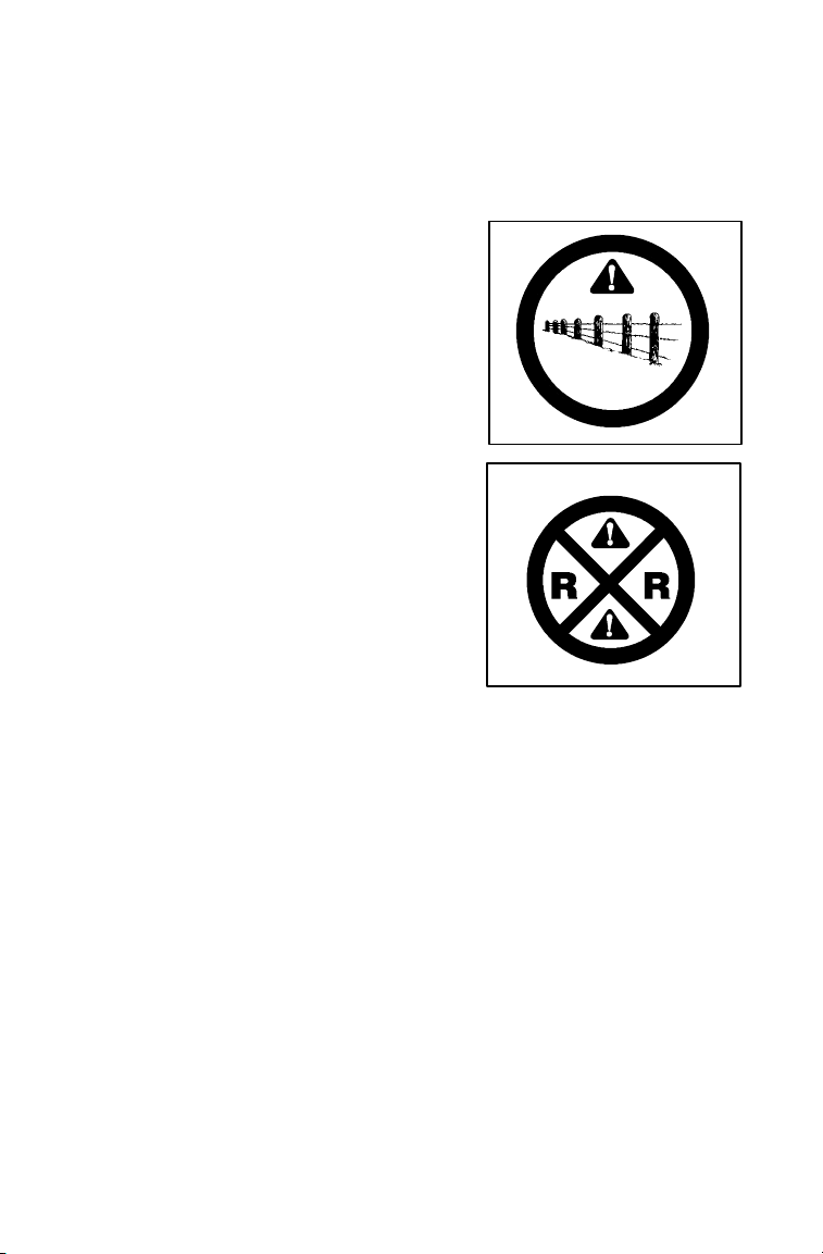
Slow down when traveling near poles,
posts, or other obstacles. Be especially
alert if you’re snowmobiling after dark.
Always be on the alert for wire fences.
Single strands are especially dangerous,
since there may be a great distance
between posts. Guy wires on utility poles
are also difficult to distinguish.
Make sure the way is clear before crossing
railroads and other roads and highways.
The noise of your machine will drown out
the sound of approaching vehicles. Look
ahead, behind, and to both sides before
turning or crossing railroad tracks or
highways. Steep embankments may also
hide your view. Always leave yourself a
way out.
Variances in snow depth and/or water
currents may result in uneven ice
thickness. Always check with local
residents or authorities for general information on conditions when
traveling on lakes and streams that are strange to you. Before riding
your machine on a frozen body of water, be sure the ice is thick enough
to support the machine and its operator, as well as the force created by
a moving vehicle. You may drown if you and the snowmobile break
through the ice.
When teaching inexperienced operators to ride, set up a predetermined
course for practice. Make sure they know how to drive and control the
snowmobile before allowing them to make longer trips. Teach them
proper snowmobile courtesy, and enroll them in driver’s training and
safety courses sponsored by local or state organizations.
18
Page 21
SAFETY
Operator Safety
Ice and Snow Build -up
WARNING
Ice and snow build-up may interfere with the steering of your
machine, resulting in serious injury or death. Keep the underhood
area free of snow and ice.
Before driving, manually turn the skis to t he left and right to be sure
ice and snow are not interfering with full left and right steering. If
difficulty is encountered, check for ice and snow build-up that may be
obstructing the steering linkage. Snow screens and bib kits are
available through your dealer to help reduce snow and ice build-up.
Operation on Hard -Packed Snow or Slippery Surfaces
WARNING
Driving on ice or hard-packed snow reduces steering and braking
control, which may result in serious injury or death. Slow down
and use caution.
Excessive shifting of operator body weight when turning on
hard-packed snow or ice may lead to loss of vehicle control and result
in serious injury or death. Slow down to maintain control under these
conditions.
It’s dangerous to drive on ice or other slippery surfaces. If it’s
unavoidable, use extreme caution and operate at speeds no faster than a
walk. Never attempt an abrupt change of direction. The chance of
“spin-out” increases under these conditions.
19
Page 22

SAFETY
Operator Safety
Driving in Hilly Terrain
WARNING
Climbing a hill or crossing the face of a slope may result in loss
of balance and machine roll-over, causing serious injury or death.
Use caution and good judgement when driving in hilly terrain.
Operating in hilly terrain requires extreme caution to maintain balance
and avoid roll-over. If climbing a hill is unavoidable, keep all your
weight low and forward.
If you must cross the face of a slope, keep your weight on the uphill
side of the machine to maintain proper balance and avoid possible
roll-over.
Slow down when reaching the crest of a hill. Be prepared to react to
obstacles, sharp drops, or other people or vehicles that may be on the
other side of the hill.
If you’re unable to continue up a hill, turn the machine downhill before
it loses momentum. If this isn’t possible, spin the track just enough to
dig in to prevent it from rolling back down the hill. Stop the engine
and set the parking brake (if equipped). Keeping away from the
downhill side of the machine, pull the rear of the snowmobile around
and point the front end and skis downhill. Remount the machine,
restart the engine, release the parking brake, and descend the hill
carefully.
20
Page 23

SAFETY
Operator Safety
Riding Downhill
When riding downhill, shift your weight to the rear of the machine and
reduce your speed to a minimum. Apply just enough throttle to keep
the clutch engaged, allowing the engine’s compression to help slow the
machine and keep it from rolling freely downhill.
WARNING
When driving on long downhill stretches, pump the brakes. Riding
the brakes may cause the brake system to overheat, which may
result in brake failure.
Excessive or repetitive use of the brakes for high speed stops will
also cause an overheated brake system. This condition may lead
to a sudden loss of brakes and/or fire and may result in serious
injury or death.
Do Not Operate Engine With Clutch Guard Removed
The clutch guard is designed to protect the operator from metal parts if
the clutch should fail. Although the chance of failure is extremely
remote, don’t defeat the purpose of the guard by removing it. It’s
provided for your safety.
Do Not Operate Engine With Drive Belt Removed
Any servicing that requires operation without a belt must be performed
by your dealer. Operation of the engine with the belt removed may
result in personal injury or damage to the engine.
21
Page 24

SAFETY
Operator Safety
Do Not Operate Engine With Intake Silencer or Filter
Removed
Damage to the engine may occur if the intake silencer or filter are
removed.
Do Not Service Clutches You rself
All clutch service must be performed by your dealer. The clutch is a
complex mechanism that rotates at high speeds. Each clutch is
dynamically balanced before installation. Any tampering may disrupt
this precision balancing and create an unstable condition.
Cold Weather Drive-Away
Whenever your snowmobile has been parked for a length of time,
especially overnight, always make sure the skis and track are loosened
from ice and snow before attempting to drive. Apply the throttle with
enough authority to put the machine into motion, but always operate
within safety limits and, on 2-Up machines, with respect for a
passenger. See page 84 for more detailed instructions on cold weather
drive-away.
Machine Maneuverability
Control and maneuverability comes not only through the steering and
skis, maximum control is achieved by shifting of body weight.
Maneuverability will change for lighter operators or machines designed
to carry a load or a passenger.
22
Page 25
SAFETY
Operator Safety
Powder Snow Operation
Moveable hood closures are included on some Polaris snowmobiles.
They are normally left open and are located on the front upper and
lower hood openings. If operating in deep snow or in extreme cold
conditions (below -20_F ), Polaris recommends closing the upper hood
closure.
WARNING
Do not drive for prolonged periods on blacktop, gravel, or ice.
Doing so could cause irreversible track damage and lead to serious
personal injury.
Since snow provides the only lubrication for the power slide
suspension and, on liquid cooled models, cooling for the engine,
adequate snow cover is a requirement for operation of your machine.
Driving in too little snow will result in excessive wear and damage to
the slide rail, track and/or engine.
If the machine becomes stuck in snow, clear the running board area of
snow, then step down the snow in front of the machine so that when
the throttle is opened, the snowmobile will be able to climb up and
over. You may then mount the machine and continue riding.
CAUTION
When operating on icy surfaces or hard-packed snow, avoid
overheating the slide rail and track. Lack of lubrication and cooling
will cause overheating of the slide rail and track, resulting in
premature wear and failure. If frequently operating in low cooling
conditions, see your dealer for an optional wheel kit that will reduce
the wear from overheating.
23
Page 26

SAFETY
Operator Safety
Your Polaris snowmobile is a well-engineered and well-constructed
recreational vehicle. Follow the recommended maintenance program
outlined beginning on page 106 of this manual to ensure that all critical
components on the snowmobile are thoroughly inspected by your
dealer at specific mileage intervals.
Driving 1-Up - Some Polaris snowmobiles are designed for a single
rider only. A decal on the console of these models indicates single
rider operation. See page 30 for decal location.
Driving 2-Up - Some Polaris snowmobiles are designed for two riders.
A decal on the hood of these models indicates that the vehicle is
designed for one operator and one passenger only. See page 30 for
decal location.
Machines designed for two riders should never be operated with more
than two people on board. When traveling with a passenger, it’s the
driver’s responsibility to operate the machine safely.
Slow down! Control becomes more difficult with two people on board.
More space is required to make turns, and longer distances are
necessary for stopping.
24
Page 27

SAFETY
Operator Safety
Responsible Driving
Every snowmobile handles differently, and even the most docile
conditions may become dangerous if operators drive improperly. If
you’re new to snowmobiling, acquaint yourself with the machine and
with what it will and won’t do under various conditions. Even
seasoned drivers should spend some time getting the feel for a machine
before attempting ambitious maneuvers.
n A snowmobile depends on the rider’s body position for proper
balance in executing turns, traversing hills, etc. Always start on a
smooth, level area to begin building your operating experience.
n Before allowing someone else use your snowmobile, know the
extent of their operating skills. Check to see if they’ve taken a
snowmobile safety course and have an operator’s certificate. For
their protection, as well as yours, make sure they take a
snowmobile safety course. Everyone can benefit from the course.
n Don’t “jump” your snowmobile. Jumping may injure your back
because of spinal compression. The seat and suspension of your
snowmobile have been designed to provide protection under
normal riding conditions. Your snowmobile is not intended for
this kind of use.
n Be courteous to oncoming traffic by dimming your headlights and
reducing your speed. Your snowmobile is equipped with a high
output headlamp system that may cause discomfort to operators of
oncoming vehicles when on high beam.
n When traveling in a group of snowmobiles, don’t tailgate (follow
too closely). Allow ample stopping distances, and keep track of
those following you. Drive defensively to avoid accidents.
n Don’t tempt anyone to steal your snowmobile or ride it without
permission. Remove the key from the ignition.
25
Page 28

SAFETY
inMPH
t
tleAdde
d
ect
Clo
the
dPers
on)
LittleAddedEffectClothedPerson)
Operator Safety
Windchill/Temperature Ch arts
The following information is provided to help you determine when
temperatures become dangerous for riding.
WIND CHILL CHART (°F)
Estimated Wind Speed
50 40 30 20 10 0 -10 -20 -30 -40 -50 -60
Calm 50 40 30 20 10 0 -10 -20 -30 -40 -50 -60
5 48 37 27 16 6 -5 -15 -26 -36 -47 -57 -68
10 40 28 16 4 -9 -21 -33 -46 -58 -70 -83 -95
15 36 22 9 -5 -18 -36 -45 -58 -72 -85 -99 -11
20 32 18 4 -10 -25 -39 -53 -67 -82 -96 -110-12
25 30 16 0 -15 -29 -44 -59 -74 -88 -104-118-13
30 28 13 -2 -18 -33 -48 -63 -79 -94 -109-125-14
35 27 11 -4 -20 -35 -49 -67 -82 -98 -113-129-14
40 26 10 -6 -21 -37 -53 -69 -85 -100-116-132-14
Wind Speeds Greater
Than 40 MPH Have
Li
Eff
Little Danger
(For Properly
Actual Thermometer Reading (°F)
Equivalent Temperature (°F)
Increasing
Danger
Danger From Freezing of Exposed Flesh
Great
Danger
2
4
3
0
5
8
26
Page 29

Operator Safety
inKPH
A
f
f
C
)
WIND CHILL CHART (°C)
SAFETY
Estimated Wind Speed
0 5 0 -5 -10 -15 -20 -25 -30 -35 -40
10 1 -4 -11 -16 -22 -27 -33 -38 -45 -50
20 -4 -9 -17 -23 -29 -36 -42 -48 -54 -61
30 -7 -13 -21 -28 -35 -42 -48 -55 -63 -69
40 -9 -16 -24 -32 -39 -47 -53 -61 -69 -76
50 -11 -18 -26 -34 -41 -49 -57 -64 -73 -80
60 -12 -19 -27 -35 -43 -51 -59 -66 -75 -82
70 -13 -20 -28 -36 -44 -52 -60 -68 -76 -84
Wind Speeds Greater
Than 70 KPH Have Little
dded E
ect
Actual Thermometer Reading (°C)
5 0 -5 -10 -15 -20 -25 -30 -35 -40
Equivalent Temperature (°C)
Little Danger
(For Properly
lothed Person
Increasing
Danger
Danger From Freezing of Exposed Flesh
Great
Danger
27
Page 30

SAFETY
Safety Decals And Locations
NOTE: Warning decals have been placed on the vehicle for your
protection. Read and follow the instructions on each decal carefully. If
any safety decal becomes illegible or comes off, contact your Polaris
dealer for a free replacement. The part number is printed on the decal.
Clutch Cover Warning Decal - 1
This warning decal is found under the hood on the clutch cover:
Do not operate engine with hood open.
Do not attempt adjustment with engine running.
Do not operate engine with this guard open.
Never run engine with drive belt removed.
Never service clutches yourself - see your dealer.
Airbox Warning Decal - 2
This warning decal is found under the hood on specific models:
Do not operate above 40 mph with hood-to-airbox foam removed or
engine failure will result.
Pressure Cap Warning Decal - 3
This warning decal is found under the hood on the pressure cap of
specific liquid cooled models:
Do not open hot. Test or replace when changing coolant. Press down
and turn to release cap. 13 PSI
28
1, 2, 3
Page 31

SAFETY
Safety Decals And Locations
Track Warning Decal - 4
The track warning decal is on the rear of
the tunnel (4):
Stay clear of track.
Do not sit on seat back or cargo area.
Combined cargo and tongue weight
should not exceed 40 lbs. (18 kg).
Cargo load affects machine steering
response.
OR
Stay clear of track. Do not sit on seat
back. Entanglement with the track or
a fall from seat back may result in
severe injury or death.
NOTE: Edge RMK models have a maximum capacity of 15 lbs (7 kg).
Cargo Carrier Warning Decal - 5
Machines with a cargo carrier will have
this warning decal on the rear rack or
on the taillight:
Do not sit in or on cargo area.
Cargo load should not exceed 40 lbs.
(18 kg).
Cargo load affects machine steering
and response.
Never allow person(s) to use carrier
as a means of hand support, (skiing,
skidding or dragging).
Severe injury may result due to track entanglement, falling off, or loss
of steering control if warnings are not followed.
4
5
29
Page 32

SAFETY
Safety Decals And Locations
Passenger Warning - 5
Some snowmobiles are
designed for the operator
only, while others are
designed for the operator and
one passenger. A warning
decal on either the console or
the hood of your machine
indicates whether it’s
designed for the operator only
(1-Up) or the operator and a
passenger (2-Up). For more
information on operating capacities, see page 24.
Decal text found on 1-Up Models:
This vehicle is designed for operator only . “NO PASSENGER”
Decal text found on 2-Up Models:
This vehicle is designed for operator and “ONE” passenger only.
5
30
Page 33

SAFETY
Safety Decals And Locations
Standard Reverse Warning Decal - 6
Some Polaris snowmobiles are equipped with reverse. These m odels
will have a reverse warning decal(s) above the instrument housing.
The decals shown here are provided for identification and location
purposes only. The text found on the decals is:
VEHICLE CAPABLE OF EXCESSIVE REVERSE SPEED!
Reverse operation may be
dangerous even at low
speeds. Steering control
becomes difficult in
reverse. Misuse of
reverse may result in
injury. Avoid turning at
sharp angles in reverse.
Transmission may not
always be in the gear
indicated by the shift lever.
Always apply throttle
slowly.
On machines with reverse it is especially important to maintain
track tension as specified in the Owner’s Manual. If specified track
tension is not maintained severe damage to the machine may
occur, which may result in loss of vehicle control. Loss of vehicle
control may result in severe personal injury or death.
For more information: See Operator’s Safety and Maintenance
Manual supplied with reverse kit.
SHIFT PATTERN
Make sure lever is shifted completely to forward or reverse
position. Do not force into reverse. If not able to shift to reverse,
apply throttle gently to move vehicle. CAUTION: Do not attempt
to shift until machine has come to a complete stop or chaincase
damage may occur.
6
31
Page 34

SAFETY
Safety Decals And Locations
Reverse Warning Decal - 7
Some Polaris snowmobiles are
equipped with electronic reverse
and will have this electronic
reverse decal:
Reverse operation, even at
low speeds, may cause loss
of control resulting in serious
injury or death. To avoid loss
of control, always:
S Look behind before and
while backing
S Avoid sharp turns.
S Shift to or from reverse only when stopped.
S Apply throttle slowly.
For more information, see your Owner’s Manual.
If electric reverse:
S Machine stopped and engine at idle, push yellow button on LH
control to reverse. Flashing light on dash indicates reverse operation.
S Push button again to return to forward.
S Elevation setting (above 6000 feet): push and hold for longer than
5 seconds to set. Let go of button at desired setting-fast flash for
high elevation, slower flash for low. Setting will remain until
changed.
7
Operation Warning Decal - 8
The console of your machine has
a WARNING decal. The location
of this decal will depend on the
model you own.
The decals shown here are offered
for identification purposes only.
The text of the decal is printed on
the next page.
32
8
Page 35

SAFETY
Safety Decals And Locations
Operation Warning Decal T ext:
S
To avoid serious injury or death, read and understand all warnings
and the Owner’s Manual before operation. If the manual is missing,
contact a Polaris dealer for a replacement.
S This vehicle is capable of high speeds. Buried objects or uneven
terrain can cause loss of control. Reduce speed and use extreme
caution when operating in unfamiliar terrain.
S Excessive speed, especially at night or with limited visibility , can
result in insufficient time for you to react to terrain changes, to
avoid unexpected obstacles, or to stop safely.
S Never consume alcohol or drugs before or while operating this ve-
hicle.
S In an emergency, push down the Auxiliary Shut-Off Switch, located
on the top of the throttle control assembly, to stop the engine. Then
pull the brake lever to stop.
S Always wear an approved helmet, eye protection, and adequate
clothing while operating this vehicle.
S This vehicle is designed for adult use only. Check local laws for age
requirements.
S When operating with a passenger (on approved models only , re-
duce speed and allow extra space for steering and stopping. A
passenger reduces your ability to control the vehicle.
S When operating on hard-packed snow, ice, or when crossing roads,
steering and braking ability are greatly reduced. Reduce speed and
allow extra space to turn or stop.
S To maintain vehicle control on ice or hard-packed surfaces, you
should have a proper balance of ski carbides to track studs. See
Owner’s Manual for proper use of traction products.
S Repeated stops from high speed may cause fading or sudden loss
of braking ability.
S Parking brake may relax when used for long periods. Do not leave
brake engaged for more than five minutes.
S Before starting the engine, check throttle, brake, and steering for
proper operation. Make sure hood is latched. Be seated and in
position to control the vehicle.
Oil injection system: Use unmixed fuel only. Check oil level when
refueling.
33
Page 36

-NOTES-
34
Page 37

SECTION 3 - FEATURES AND CONTROLS
Location of Controls 36 - 38...................
Features 39 - 41..............................
Section 3 illustrates the locations of your snowmobile’s controls and
features.
35
Page 38

FEATURES AND CONTROLS
Location of Controls
NOTE: Your machine may not look exactly like the illustration, but
these controls are found in the same general area on all machines.
45
6
3
7
8
2
1
10
9
1. Fuel Filler Cap (some models have a fuel gauge in the cap)
2. Ignition Switch
3. Brake Lever
4. Speedometer (may include indicator/warning lights)
5. Tachometer (may include indicator/warning lights)
6. Engine Stop Switch (Push/Pull) Operation found on page 96.
7. Throttle Control
8. Hood Hold Down Straps
9. Recoil Starter Handle
10. Choke Control
36
Page 39

FEATURES AND CONTROLS
Location of Controls
NOTE: Some Polaris
snowmobiles are
equipped with special
features. Controls for
these features are illustrated on this page. Not
all models come with
these features. Refer to
your Owner’s Manual
Supplement for a list of
features on your
machine. Accessories
are available from your
Polaris dealer.
1. Headlight Dimmer
Switch (2 Position)
2. Park Brake
3. Handlebar Grip
Warmer Switch
4. Thumbwarmer
Switch
5. Electronic Reverse
Button
6. Electronic Shock
Control Button
7. Tether Switch
2
3
1
6
1
3
4
5
3
7
37
Page 40

FEATURES AND CONTROLS
Location of Controls
NOTE: Some P olaris snowmobiles are equipped with special features.
Controls for these features are illustrated on this page. Not all models
come with these features. Refer to your Owner’s Manual Supplement
for a list of features on your machine. Accessories are available from
your Polaris dealer.
1. Reverse Indicator
Light
2. Electronic Fuel
Gauge
3. Temperature Light
4. Electric Shock
Absorber Gauge
12
3
1
3
4
38
Page 41

Features
16
FEATURES AND CONTROLS
3
2
1
4
5
10
17
19
8
6
7
18
15
13
14
12
11
9
1. Hood 12. Suspension
2. Headlight 13. Nosepan
3. Windshield 14. Trailing Arm
4. Handlebar 15. Skis
5. Seat 16. Front Bumper
6. Storage/Rear 17. Console
7. Taillights 18. Rear Bumper
8. Backrest 19. Lifting Hand Hold
9. Tunnel Extension 20. Snow Flap
10. Passenger Hand Hold Strap
11. Track
20
39
Page 42

FEATURES AND CONTROLS
Features
16
15
22
3
2
1
13
14
4
5
12
6
18
7
20
11
1. Hood 12. Suspension
2. Headlight 13. Nosepan
3. Windshield 14. Trailing Arm
4. Handlebar 15. Skis
5. Seat 16. Front Bumper
6. Storage/Rear 17. Console
7. Taillights 18. Rear Bumper
8. Backrest 19. Passenger Hand Hold
9. Tunnel Extension 20. Lifting Hand Hold
10. Passenger Hand Hold Strap 21. Snow Flap
11. Track 22. Hood Closures (Edge
Models Only)
40
Page 43

Features
FEATURES AND CONTROLS
15
3
2
1
16
14
13
17
11
8
19
6
7
9
20
4
10
5
12
1. Hood 12. Suspension
2. Headlight 13. Nosepan
3. Windshield 14. Trailing Arm
4. Handlebar 15. Skis
5. Seat 16. Front Bumper
6. Storage/Rear 17. Console
7. Taillights 18. Rear Bumper
8. Backrest 19. Passenger Hand Hold
9. Tunnel Extension 20. Lifting Hand Hold
10. Passenger Hand Hold Strap 21. Snow Flap
41
Page 44

-NOTES-
42
Page 45

SECTION 4 - THE PERFECT FIT
Front Suspension Adjustments 44 - 48.........
Rear Suspension Adjustments 49 - 58.........
M-10 Suspension 59 - 68......................
Handlebar Adjustment 69.....................
Backrest Adjustment 70......................
Accessories 71 - 74..........................
Polaris offers a wide range of adjustments so that every machine may
be set up to suit individual needs. This section explains how to tailor
the suspension and other features for an optimum riding experience.
43
Page 46

THE PERFECT FIT
Front Suspension Adjustments
Break in the suspension for approximately 150 miles (240 km) and
re-grease all suspension parts before fine-tuning adjustments are made.
Settings will vary from rider to rider, depending on rider weight,
vehicle speed, riding style, and trail conditions. We recommend
starting with factory settings and then customizing each adjustment
individually to suit rider preference. The machine should be
methodically tested under the same conditions after each adjustment
(trail and snow conditions, vehicle speed, riding position, etc.) until the
best ride is achieved. Adjustments should be made to one area at a
time in order to properly evaluate the change.
All snowmobile suspensions have a front and a rear suspension, each
of which has adjustment options.
Independent Front Suspension (IFS)
The IFS is made up of the skis
(1), front shocks and springs
(2), and the components that
connect these parts to both the
steering, such as the tie rods
(3), and to the machine itself,
such as the trailing arms (4).
Front suspension adjustments
include shocks, springs, toe,
and camber.
NOTE: Although the front suspension on your machine may
not look exactly like the illustration, it will have the same
parts and functions as those
illustrated.
1
2
3
4
IFS Adjustment Options
D Front shock spring preload
D Optional springs
D Optional valving (if equipped with RYDE FX
D Indy Select (if equipped)
44
t or Foxt Shocks)
Page 47

THE PERFECT FIT
Front Suspension Adjustments
WARNING
Always verify ski alignment before making adjustments to the IFS.
See page155 to check alignment. If the skis are misaligned, see
your dealer, as the camber adjustment may also be affected.
The tension at which the shock coil spring is set is called spring
preload. For the best ride, the spring preload should be set as low as
possible to use the full travel of the ski shock, with occasional light
bottoming. To determine if your machine is using full travel of the ski
shock, push the jounce bumper down as far as it will go on the shock
rod and test ride the machine. The bumper will move up on the rod in
direct relation to the amount of travel. If the shock travel is full, the
bumper will be seated at the top of the shock.
Shock Absorber Components
1. Retainer
2. Shock Rod
3. Jounce Bumper
4. Body
5. Threaded Spring Preload Adjuster Nut
1
2
3
4
5
45
Page 48

THE PERFECT FIT
Front Suspension Adjustments
Adjusting Front Shock Spring Preload
Increasing spring preload will increase
ski-to-ground pressure. Decreasing
spring preload will decrease
ski-to-ground pressure. When
adjusting, be sure springs on both the
left and right sides of the machine are
at the same adjustment.
To increase front shock spring preload,
grasp the spring and turn it to the
right. Turn it to the left to decrease
preload. In the illustrations at right, B
indicates high preload and C indicates
low preload.
Increasing the spring preload too much may adversely affect the
handling of the snowmobile and the performance of the rear
suspension. Decreasing the spring preload too much may allow the
upper spring retainer to fall off. Always leave at least one thread
showing above the nut (A).
A
B
C
CAUTION
Always leave one thread showing above the adjuster nut.
On models equipped with a plastic adjuster nut, if the nut is
unscrewed from the threaded body, the nut will break.
46
Page 49

THE PERFECT FIT
Front Suspension Adjustments
If the spring preload is at its maximum and you want more adjustment:
D Remove the existing spring and install the next highest rate spring,
or
D Change the shock valving on Fox
Evanst shocks, or
D Increase compression damping on Indy Select shocks (PE 52)
See your dealer for details.
NOTE: Some models do not have shocks with thread adjustable spring
preload.
Changing Shock Valving
If you find that spring preload adjustment alone is not sufficient,
changing the valving of your Fox
you the ride adjustment you want. The purpose of shock valving is to
control the stiffness of the shock’s movement.
t, RYDE FXt, and Walker/
t or RYDE FXt shocks may give
WARNING
Changing shock valving on Foxt and RYDE FXt shocks
requires special tools and a sound knowledge of mechanical
theory, tool use, and shop procedures to perform the work safely
and correctly. Shocks contain high-pressure nitrogen gas. Use
extreme caution when handling high-pressure service equipment.
This work should be performed by a Polaris dealer.
47
Page 50

THE PERFECT FIT
Front Suspension Adjustments
Indy Select IFS Shock
Some snowmobiles are equipped with Indy Select IFS shocks, which
allow you to make adjustments to the compression valving of the front
shocks by turning adjustment screws (A) located near the base of the
shocks.
By turning the screw clockwise, the compression of the shock
increases, stiffening the ride. By turning counterclockwise, the
compression decreases, softening the ride.
The factory setting is in the softest position (screw all the way out counterclockwise). If bottoming occurs, the Indy Select feature should
be used to achieve the desired ride effect. One-half turn will affect the
ride considerably. There are about three turns of adjustment available.
If experimenting with this adjustment feature, turn the screw only 1/4
turn at a time. And always adjust both shocks equally.
48
A
Page 51

THE PERFECT FIT
Rear Suspension Adjustments
Rear Suspensions
Polaris has a suspension t o meet your needs. Each is designed and set
up to deliver a soft ride under average riding conditions. Rider weight,
riding style, trail conditions, and vehicle speed all affect suspension
action.
Each rear suspension can be adjusted to suit rider preference and
deliver excellent performance for a given set of conditions. However,
all suspension designs and adjustments involve a compromise, or
trade-off. For example, a suspension set up for snow-cross racing
would provide a very stiff ride on the trail. A suspension set up for
trail riding would bottom out harshly on a snow-cross course.
A decal outlining rear suspension set-up options is located either under
the hood or on the clutch cover. It provides a guideline for initial
suspension set-up. Additional adjustments can be made from this
point. Make adjustments to one area at a time so you can evaluate the
change. For further assistance, see your dealer.
Suspension Performance Tips
D Rider weight usually determines the position at which the spring
preload should be set. However, this may vary with riding style.
With a little experimentation, each rider can find a preferred set-up.
These adjustments are easy to make, involve very little time or effort, and greatly affect the ride.
D In deep snow, a new Hi-fax will offer improved performance over
worn Hi-fax. It can also improve top speed.
D When riding on ice or hard-packed snow, adding a set of bogie
wheels to the rail may enhance the machine’s performance. Bogie
wheel kits are available from your dealer.
D Polaris offers track kits for improved flotation in deep snow. See
your dealer for assistance.
NOTE: Keep the suspension pivot points lubricated. This will reduce
moisture and rust build-up and ensure proper function of the
suspension components. Grease rear suspension pivots before
adjusting the rear suspension. Refer to Suspension Maintenance on
pages 158-159.
49
Page 52

THE PERFECT FIT
Rear Suspension Adjustments
Rear Suspension Initial Spring Preload Setting
EDGE RMK (Sag Method)
T o set up the EDGE RMK rear
suspension torsion spring preload,
measure the distance between the
ground and rear bumper. This is
measurement X.
Take this measurement with no rider
and with the rear suspension at full
extension. NOTE: The rear bumper
may need to be lifted upward
slightly to fully extend the
suspension.
Next, have the rider drop down hard
on the seat and bounce up and down
several times, collapsing t he rear
suspension. With the rider seated,
measure the distance between the
ground and the rear bumper at the
exact location used for measurement
X. This is measurement Y.
To determine sag, commonly
referred to as ride-in, subtract
measurement Y from X (Sag=X-Y). Adjust sag by rotating the torsion
spring preload cams located on the rear torque arm. Use the illustration
or the decal found under the hood for reference. The ideal amount of
sag for the EDGE RMK rear suspension is four inches (X-Y=4).
If the rear suspension rides in less than three inches or more than five
inches with the torsion spring preload cams at their maximum range of
adjustment, optional torsion springs (softer or stiffer, respectively) may
be required. This is only an initial setup, and final spring preload may
vary based on rider preference and riding conditions.
X
Y
50
Page 53

THE PERFECT FIT
Rear Suspension Adjustments
Rear Spring Tension
To adjust rear torsion spring tension, rotate the three-position cam
using the engine spark plug tool.
Different rate torsion springs are available if a firmer ride is desired.
Contact your dealer for more information.
The following information is provided only as a guideline to be used
for initial suspension set-up. Your set-up may vary based on your
desired riding style.
3a
2a
2b
1
3b
4a
4b
1 - Turn screw clockwise to stiffen compression
2a - Limiter strap in high position increases ski pressure
2b - Limiter strap in low position decreases ski pressure
3a - Turn the knob to the left for a softer ride
3b - Turn t he knob to the right for a stiffer ride
4a - Soft Tension - long end of cam to front
4b - Medium tension - short end of cam up
4c - Firm tension - long end of cam up
4c
51
Page 54

THE PERFECT FIT
Rear Suspension Adjustments
Rear Suspension Initial Spring Preload Setting
Xtra-10, EDGE and Xtra Lite (Sag Method)
To set up the EDGE rear suspension
torsion spring preload, measure the
distance between the ground and rear
bumper. This is measurement X.
Take the first measurement with no
rider and with the rear suspension at
full extension. NOTE: The rear
bumper may need to be lifted upward
slightly to fully extend the rear
suspension.
Next, have the rider drop down hard
on the seat and bounce up and down
several times, collapsing t he rear
suspension. With the rider seated,
measure the distance between the
ground and the rear bumper at the
exact location used for measurement
X. This is measurement Y.
To determine sag, commonly referred
to as ride-in, subtract measurement Y
from X (Sag=X-Y). Adjust sag by
rotating the torsion spring preload cams located on the rear torque arm.
Use the illustration or the decal found under the hood for reference.
The ideal amount of Sag for the EDGE rear suspension is four inches
(X-Y=4).
If the rear suspension rides in less than three inches or more than five
inches with the torsion spring preload cams at their maximum range of
adjustment, optional torsion springs (softer or stiffer, respectively) may
be required. This is only an initial set-up, and final spring preload may
vary based on rider preference and riding conditions.
X
Y
52
Page 55

THE PERFECT FIT
Rear Suspension Adjustments
Rear Torsion Spring Adjustment - Xtra-12
To adjust rear torsion spring tension,
rotate the t wo-position cam using the
engine spark plug tool.
1a - Soft Tension - long end of cam to
front
1b - Medium Tension - short end of cam
up
Different rate torsion springs are available
if greater tension is desired. Contact your
dealer for more information.
1a
1b
53
Page 56

THE PERFECT FIT
Rear Suspension Adjustments
Indy Select Front Track Shock
Some snowmobiles are equipped with the Indy Select front track
shock, which allows the driver to make adjustments to the compression
valving by turning the screw located near the base of the shock.
Adjustment
Locate the adjustment screw (A) near the base of the shock. In
half-turn increments, turn the screw clockwise to increase compression
valving and stiffen the ride, or counterclockwise to reduce compression
and soften the ride. There are approximately three full turns of
adjustment available.
A
54
Page 57

THE PERFECT FIT
Rear Suspension Adjustments
Indy Select Rear Shock
Some snowmobiles are equipped with the Indy Select rear shock,
which allows for adjustments to the compression valving by turning
the adjustment screw located near the base of the shock.
Adjustment
Locate the adjustment screw (A) near the base of the shock. In
half-turn increments, turn the screw clockwise to increase compression
valving and stiffen the ride, or counterclockwise to reduce compression
and soften the ride. There are approximately three full turns of
adjustment available.
If bottoming continues after the screw has been turned fully clockwise,
the torsion spring should be adjusted (see page 53). Return the screw
to its original starting position after the torsion spring has been
tightened.
A
55
Page 58

THE PERFECT FIT
Rear Suspension Adjustments
Optional Coil Springs
Different rate coil springs are available for some shocks if a firmer ride
is desired. Contact your dealer for more information.
Position Sensitive Shock (PPS)
There are no external adjustments on the position sensitive shock.
There is a performance PPS kit available for increasing damping. If
you desire to have the internal valving changed, consult your dealer, or
refer to the suspension troubleshooting decal located under your hood
or on the clutch guard.
Suspension Coupling
On all Polaris snowmobile rear suspensions, there are two torque arms
that control the movement of the rail beam. Prior to the advent of
suspension coupling, these torque arms could move independently of
each other. Rear suspension coupling links the movement of the front
and rear torque arms to each other. There are two types of rear
suspension coupling.
Front To Rear Coupling and the Front Rear Scissor
Stop (FRSS)
The front rear scissor stop (FRSS) couples the movement of the front
torque arm with the rear torque arm and limits the amount of
independence between the movement of the front torque arm and the
rear torque arm.
When hitting a bump, the front torque arm starts to compress. The
FRSS links that movement to the rear torque arm, causing it to
compress and raise the rear suspension up as one, allowing the
suspension to hit the bump only once and eliminating kickback. Your
FRSS is preset at the factory.
56
Page 59

THE PERFECT FIT
Rear Suspension Adjustments
Rear To Front Coupling and the Rear Rear Scissor
Stop (RRSS)
The rear rear scissor stop (RRSS) couples the movement of the rear
torque arm with the front torque arm and limits the amount of
independent movement between the rear torque and the front torque
arm.
Adjusting the RRSS either allows more weight to transfer to the rear
for more traction, or allows less weight to transfer to the rear, resulting
in improved cornering performance. An adjustment dot is located on
the RRSS. This dot is on the longest end of the scissor stop.
Rear Rear Scissor Stop (RRSS) - Attributes
Moving the RRSS to a higher position, or forward hole, will have the
following effects on the suspension:
D Reduced weight transfer.
D Improved chatter bump ride.
D Improved cornering performance.
57
Page 60

THE PERFECT FIT
Rear Suspension Adjustments
Weight Transfer During Acceleration
Xtra-10 and EDGE Rear Rear Scissor Stop (RRSS)
The preferred method for controlling
weight transfer during acceleration of
the EDGE rear suspension is by
adjusting the rear rear scissor stop
(RRSS). The RRSS is located in the
best overall trail riding position when
delivered from the factory.
To decrease weight transfer under
acceleration (for improved cornering),
rotate the RRSS to a higher position
with the scissor stop tool (1) located in
your tool kit.
To increase weight transfer or ski lift
during acceleration, move the RRSS to
the rearward hole on high position. The
RRSS may also be rotated to a lower
position for even more weight transfer
if desired.
A - Stock Position - This setting is
most desirable for trail riding.
B - Medium or High Position (standard
hole location) - This setting will
decrease weight transfer.
C - Rearward Upper Position (optional
hole location - This setting will
increase weight transfer.
NOTE: Your dealer can help you with initial set-up and additional setup instructions to help you achieve your optimum ride.
Xtra-12 Rear Rear Scissor Stop (RRSS)
The RRSS on Xtra-12 suspensions is not adjustable.
1
A
B
C
58
Page 61

THE PERFECT FIT
M-10 Suspension
Before proceeding with the tuning of your M-10 suspension, you
should familiarize yourself with the following terms:
Description of M-10 Features
Long Travel - Refers to the over 10″ of REAL travel that the M-10 has
between the rear arm cross-shaft and the slide rail. this is the location
to measure suspension vertical travel. In the Edge Chassis, the rear axle
travel is 13.9”.
Biased Couple - Describes the linked relationship between the front
and rear arms of the M-10. When the M-10’s front arm contacts a
bump, the couple forces the rear arm to react instantly. This limits the
angle of incidence between the rail and bump as the rear arm crosses it.
the flatter this angle is kept, the less secondary reaction (kick) the rider
will feel, and better maintenance of TRACK TENSION can be attained
through the full 10″ travel.
Couple Blocks - Are the plastic sliding blocks located at the rear of the
rail. These pieces facilitate the M-10’s actual couple function.
Advanced Ride Control (ARC) - ARC geometry decelerates shock
and spring speed throughout compression travel making the shocks
very sensitive to sled speed. This enables large strokes to be used in
nearly all conditions, high or low speed, delivering huge benefits in
rider comfort.
On return travel, the shock speed or rate is increased, which in effect
delivers “RISING RATE” on the rebound stroke. The mechanical
advantage of the system over the stored spring energy is very high,
especially when compared with conventional systems. The result is
excellent control of the “kick” and normal return forces which FAST
has identified as being the most upsetting to the rider during travel over
rough conditions.
Full Range Adjuster (FRA) - FRA refers to the adjustable lower rear
shock attachments. Major adjustments in rider weights can be made
from 100 lbs. at the rear (#1 SOFT position of the slot) to 350 lbs at
the front (#4 FIRM position of the slot). Changing this location has
two effects on tuning. Moving the shock forward increases shock
speed, resulting in firmer damping on both compression and rebound.
It also increases the effect of the rear spring by displacing it further.
The adjuster is infinitely variable between those settings. Using a
9/16″ wrench, adjustments are made quickly and easily.
59
Page 62

THE PERFECT FIT
M-10 Suspension
NOTE: The M-10 has been designed to be very sensitive to rider
weight. Changes in rider weight of 25 lbs. or more might require appropriate changes in FRA settings. Refer to the chart on page 64 for
specifications.
Internal Floating Piston Shock - A high-pressure gas shock absorber,
with its gas reservoir inside the main shock body. Shock oil, is kept
separate from the gas by m eans of a floating internal piston. The shock
used on the front arm of the M-10 is of this type. The advantages of
these shocks are consistency and reduced fade performance.
Remote Reservoir Shock - When a shock’s nitrogen and oil are
separated by a floating piston or bladder in an external chamber, they
are referred to as REMOTE RESERVOIR shocks. Some advantages of
this type of shock are consistency in shock performance, reliability, and
reduced fade performance. The M-10’s rear shock absorber is of this
type.
Threaded Preload Adjuster - The top section of the X-OVER TUBE
(back tube at the top of the rear shock) has a threaded collar on it. The
rear spring has a lock tab that fits into the collar to allow easy
PRELOAD adjustment.
T o increase PRELOAD, use a kit spanner wrench to rotate the
X-OVER TUBE towards the PTO side of the sled (clockwise when
viewed from below). Rotate towards the MAG side to decrease
PRELOAD (counter-clockwise when viewed from below). For more
information, refer to page 65.
DEFINITION OF TUNING TERMS
Spring Rates - Describes how many pounds of force it takes to
compress a spring one inch. Therefore, if a 250 lb weight was set on
top of a spring and it compressed one inch, it would be rated at 250
lbs/inch.
60
Page 63

THE PERFECT FIT
M-10 Suspension
Optional S pring Rates - Optional springs have been designed to allow
adaptation of the M-10 to the varied needs of our customers. The 140
lb/in option front arm spring would be used when very light loads are
encountered such as very smooth trails, deep powder or by very light
riders.
The 235/415 lb rear arm spring option would be used by riders in high
load situations such as heavy riders on rough trails or combined total
rider weight of over 350 lbs.
The available springs for M-10 are as listed below.
Location Spring Rate Polaris PN
Front Arm Std
Soft
Firm
Rear Arm Std
Soft
Firm
Overload 1000 7041936--067
Preload - Is basically the pretensioning of a spring by installing it on a
shock at less than its free length - Free Length -- installed Length =
Inches of PRELOAD OR 10.5″ -- 9.75″ =.75″ of PRELOAD
Dual Rate - Refers to 2 different SPRING RATES designed into one
spring. Notice that M -10 coil springs are often “dual rate” having a
soft (closely wound) area and a firm (loosely wound) area.
Over Load Spring - Located inside the main rear spring, contact is
made with this spring only when the X-OVER tube comes in contact
with it towards the end of the travel, reducing bottoming of the rear
suspension.
X-OVER or CROSS OVER - Describes the transition from one
spring rate to another. during compression travel, the space between
the closely wound coils eventually disappears. At this point, the spring
“CROSSES OVER” from the soft to the firm rate. This term also
includes the transition that occurs when the overload s pring is engaged
by the “X-Over Tube” on the rear shock.
160 lb/in
140 lb/in
180 lb/in
210/278 lb/in
135/240 lb/in
300 lb/in
7041671-216
7041677-067
7041672-067
7041935-216
7042010-067
704201 1-067
61
Page 64

THE PERFECT FIT
M-10 Suspension
SAG SETTINGS - Describes the difference in height of the rear
bumper from the sleds fully extended position to its loaded height with
the rider seated on the sled.
A good initial starting point is 4″ of SAG. Note that this measurement
is at the rear bumper. Too much SAG will result in bottoming and too
little SAG will result in reduced rider comfort.
SAG travel i s used to control ride quality and rebound travel and off
the tops of bumps. SAG is controlled by FRA and PRELOAD
settings. For more information, refer to the INITIAL SET-UP
REFERENCE CHART found on page 64, or the suspension set up
decal located under the hood of the snowmobiles.
INITIAL SET UP AND CALIBRATION
Your M-10 is a precision instrument which MUST be optimized for
your specific needs and riding conditions. The following introduction
and information has been compiled to assist you in tuning your M-10
to its maximum potential.
62
Page 65

THE PERFECT FIT
M-10 Suspension
Rear Suspension Setup
1. Adjusting the Full Range Adjuster (F.R.A.)
1. Refer to the initial set-up reference chart (located under the hood of
your snowmobile and on page 64) to determine the desired F.R.A.
position.
2. To adjust, loosen the hex bolts (A)attaching the rear lower shock cross
shaft to the rail beam.
3. Using a 9/16” wrench, loosen the jam nuts (B) on the preload bolts.
4. Adjust the preload bolts (C) to the desired F.R.A. position.
5. Tighten the jam nuts (B). NOTE: Make certain the preload bolt is
contacting the slide block before tightening the jam nut.
6. Tighten the hex bolts (A) and torque to 35 ft. lbs.
NOTE: The FRA setting is the primary rear suspension adjustment. It
will have the MOST effect on the rear suspension performance.
If the M-10 is new, it will take anywhere from 25 to 200 miles to
properly break in the springs and shocks. At the time of break-in, the
suspension will get softer and may require the FRA to be re-adjusted
A
B
C
63
Page 66

THE PERFECT FIT
g
A
A
Leng
g
fullridin
g
PositionPositionPreloadLengthSettings
M-10 Suspension
INITIAL SET-UP REFERENCE CHART
This chart is a guideline to be used for initial suspension setups. Your setup
may vary based on your desired riding style.
FRA Location A DimensionBDimension
C
Rider
Weight with
full ridin
gear
100 Lbs 1 11/4 005 5/8 143 4/4 3/3
125 Lbs 1 11/2 005 13/16 148 4/4 3/3
150 Lbs 1 11/2 5/16 8 5 13/16 148 4/4 3/3
175 Lbs 11/2 2 5/16 8 5 13/16 148 4/4 3/3
200 Lbs 2 21/2 5/16 8 5 3/4 146 4/4 3/3
225 Lbs 21/2 3 5/16 8 5 5/8 143 4/4 3/3
250 Lbs 3 31/2 5/16 8 5 9/16 141 4/4 3/3
275 Lbs 3 31/2 1/2 13 5 7/16 138 4/4 3/3
300 Lbs 3 31/2 1/2 13 5 3/16 132 4/4 3/3
325 Lbs* 3 31/2 5/8 16 5 3/16 132 4/4 3/3
350 Lbs* 31/2 4 5/8 16 5 3/16 132 4/4 3/3
375 Lbs* 4 5 7/8 22 5 3/16 132 4/4 3/3
SOFT
FR
Position
FIRM
FR
Position
Rear
Spring
Preload
In / mm In / mm Light / Firm
X-over
Tube
th
Settings
Limiter/Ski
Pressure
Settin
s
TUNING NOTE: These positions are only preliminary.
Experimentation should follow INITIAL SETUP to obtain optimum
results. Refer to the suspension trouble shooting decal for additional
set-up tips.
* Optional spring suggested. Refer to the list on page 61.
64
Page 67

THE PERFECT FIT
M-10 Suspension
Setting the Rear Compression Spring Preload
Dimension B
1. Using the spanner
wrenches in your tool kit,
rotate the x--over tube
assembly to achieve the
desired spring preload
setting. Be certain the
aluminum locknut and
adjuster collar are locked
against each other before
starting adjustment.
2. While adjusting, keep in
mind that spring preload
is a FINE adjustment.
COARSE adjustments
should be made using the
FRA.
NOTE: Preload is set “softest” when the preload dimension (B) is
equal to zero. Adjusting spring preload beyond this could cause damage to the threads.
B
C
Adjusting the X-over Tube Length - Dimension C
1. Use the spanner wrenches located in the tool kit to unlock the upper
lock nut from the adjuster collar.
2. Turn the adjuster collar to the appropriate or desireddimension for the
rider’s weight (refer to the initial set-up reference chart located under
the hood of your snowmobile). Tighten the upper lock nut firmly
against the adjuster collar using the spanner wrenches.
NOTE: The correct setting of the X-Over tube length enables the M-10
to deliver superior performance in “bottoming” situations. This
adjustment has no effect on spring pre-load or general ride
characteristics of your M-10 rear suspension, only bottoming
resistance.
65
Page 68

THE PERFECT FIT
M-10 Suspension
SETTING LIMITER / SKI PRESSURE
Your M-10 rear
suspension has come
from the factory set up
to delivery the optimum
balance between ride
and handling. If a rider
4
3
2
1
prefers more ski
pressure for improved
steering performance,
adjustments can be
made to the front limiter
strap.
2
3
4
1. To set t he limiter, determine if the rider prefers comfort or control.
Lean toward the #4 setting for comfort and towards the #3 settings for
aggressive riding.
2. For full hole adjustments remove the 5/16” nut and flat washers from
the lower attachments of the limiter straps and relocate straps to the
desired position (i.e. position 4 to 3). Replace the nut and washer and
re-tighten.
For half-hole increments
(such as 3/4), the limiter
straps have slots at the
B
A
upper pinch bolt. These
slots allow the bolts to
be loosened (rather than
removed) for half-step
adjustments. It is now
easy to change to half-step hole positions (re-tighten pinch bolts if
loosened).
3. FRONT ARM MOUNTING HOLES. There are also 2 front arm
mounting holes in the slide rail that can adjust ski pressure. The lower
hole (A) increases ski pressure while the upper hole (B) decreases ski
pressure.
NOTE: By design, the B IASED COUPLE suspension system
displaces the rear arm as the front arm is compressed. This means that
when you raise the front limiter strap at some point you will collapse
the rear suspension arm, which will affect SAG height, and reduce rear
suspension travel.
66
Page 69

THE PERFECT FIT
M-10 Suspension
SAG / RIDE HEIGHT SETTINGS
1. To check if the FRA settings are close before riding, check the SAG
settings. Raise the rear bumper until the suspension i s fully extended
(rearshock will not extend any further) and measurethe distance from
the ground to the bottom of the bumper as shown to attain dimension
X and record it.
2. Next, have the rider sit on the sled and bounce on the seat a couple of
times to set in the M-10. While the rider remains seated, m easure the
distance from the ground to the top of the bumper to attain dimension
Y and record it.
3. Next subtract Y from X and you will have the S AG settings (X -- Y =
SAG SETTING or 21 -- 17 = 4). The correct amount of SAG for the
M-10 rear suspension is 3” - 5”.
NOTE: The FRA setting is the primary rear suspension adjustment. It
will have the MOST effect on the rear suspension performance.
Unloaded
Loaded
X
Y
67
Page 70

THE PERFECT FIT
M-10 Suspension
TRACK TENSION
Track adjustment is
critical for proper
handling. Always
maintain correct tension
and alignment.
Tension adjustments
should be made only after
the track is warmed up
and limber.
1. Turn the machine off.
2. Lift the rear of the
machine and safely
support it off the
ground.
NOTE: Measure at a
point 16” ahead of the
center of the rear idler
wheel.
3. Check for 1/2 - 3/4” free-hanging slack between the wear surface of
the track clip and the plastic hi-fax (C).
If the t rack needs adjustment:
4. Loosen rear idler shaft bolts (D) and locknuts (A).
5. Tighten or loosen the track adjusting screws (B) as necessary to
provide equal adjustment on both sides of the track.
6. Tighten Locknuts (A). Then tighten the idler shaft bolts (D) to 35 ft.
lbs.
NOTE: Always inspect track alignment after track tension adjustment.
Track alignment affects track tension. misalignment will cause
excessive wear to the track and slide rail. Excessive Hi Fax wear will
appear on units with track tension set too tight. Refer to the Master
Repair Manual for track alignment procedure.
Hi-fax
C
Track
A
B
D
68
Page 71

THE PERFECT FIT
Standard Handlebar Adjustment
Follow these steps to adjust the handlebars for a personal fit.
1. Remove the handlebar cover to
expose the handlebar and the four
adjuster block bolts (A).
2. Using a 7/16″ (11 mm) wrench,
loosen the four nuts on the bottom
of the adjuster block (turn handlebar
to left or right for access to back
nuts).
NOTE: It may be necessary to pry the
adjuster blocks apart with a screw driver.
3. Adjust the handlebar to the desired height. Be sure handlebars,
brake lever and t hrottle lever operate smoothly and do not hit the
gas tank, windshield or any other part of the machine when turned
fully to the left or right.
4. Torque the handlebar adjuster block bolts to 11-13 ft. lbs. (1.5-1.8
kg/m).
5. Replace handlebar cover.
Vertical Handlebar Adjustment
1. Remove the handlebar cover to
expose the handlebar.
2. Using a 7/16” (11 mm) wrench,
loosen either two nuts on the bottom
of the riser OR two nuts on the top
of the riser, depending on the
adjustment required.
3. Adjust the handlebar to the desired
height. Be sure handlebars, brake
lever and throttle lever operate
smoothly and do not hit the gas
tank, windshield or any other part of the machine when turned
fully to the left or right.
4. Torque the handlebar adjuster block bolts to 11-13 ft. lbs. (1.5-1.8
kg/m).
5. Replace handlebar cover.
A
69
Page 72

THE PERFECT FIT
Backrest Adjustment
The passenger backrest on some
models is adjustable.
To move the backrest forward or
backward, lift the adjustment
lever on the left side (1).
When adjusting the backrest from
a passenger position to a single
rider position, rotate the backrest
cushion adjustment knobs (2)
until the proper angle is reached.
Thegrabbarshavefiveheight
adjustments. To raise or l ower the
grab bar, remove the grab bar
adjuster knob (3), position t he grab bar at the desired height, and
reinstall the knob.
Some models are also equipped with passenger handwarmers. The
switch (4), located under the left--hand wind deflector, has three
settings: High, Off, and Low.
To lengthen or shorten the backrest cable, lift the cable until spring
tension is felt and lock the jam nut.
4
3
2
1
70
Page 73

THE PERFECT FIT
Accessories
Polaris offers a wide range of accessories for your snowmobile. From
map light to electric start, Polaris has the accessories that will help
make each ride more enjoyable. See your dealer for a list of
accessories.
NOTE: The accessory tether switch is available for all models. Order
PN 2870668.
Use only Polaris parts and accessories on your Polaris snowmobile.
Use of unapproved parts and accessories may result in:
D Non-compliance with government/industry requirements
D Voiding of warranty
D Personal injury to self or others
This applies t o, but is not limited to the following areas: brakes,
clutches, fuel systems, and exhaust systems.
NOTE: Exhaust systems are critical safety areas that must use ap-
proved Polaris parts. Please see your Polaris dealer for service.
71
Page 74

THE PERFECT FIT
Accessories
Traction Products
Another way to tailor your machine is to install traction products. See
your dealer about installing studs and/or carbides. Many tracks with
deep lug designs cannot be studded, but your dealer will be able to
offer advice and assistance.
NOTE: Polaris does not recommend the use of traction products on
WideTrak snowmobiles.
Traction Products
NOTE: Before equipping your machine with traction products, be
aware of the laws in your area pertaining to the use of traction
products.
Track studding will enhance braking control on hard-packed snow or
ice, but extreme caution is still required on such surfaces. Steering
ability may be reduced on hard-packed snow or ice.
A skag is a replaceable bar attached to the underside of the ski to assist
in turning the snowmobile and to prevent ski wear caused by contact
with roads and other bare terrain. The addition of carbide skags is
recommended with studded tracks to help maintain proper vehicle
steering and control. Similarly, if your machine is equipped with
carbide skags or you’re adding them, it may be necessary to add track
studs to maintain proper vehicle control. Proper balance must be
maintained between the number of studs and the length of carbide on
skags. The more studs used, the longer the carbide on the skags should
be. See your dealer’s track studding chart for recommended studding
and skags.
Inspect skags and studs frequently. Worn studs or skags may reduce
steering and braking control on hard-packed snow and ice. Replace
worn studs and skags to maintain proper balance and vehicle control.
When studded tracks are used, increased wear to the brake pads will
result from increased braking. Extended-wear brake pad kits are
available. See your dealer for more information.
72
Page 75

THE PERFECT FIT
Accessories
CAUTION
Aggressive studding patterns may require grinding protruding stud
bolts flush to prevent idler wheel damage. Maintain track tension
on studded tracks on the tight side of the spec to prevent heat
exchanger damage. Center of stud must be at least 1 1/8″ (2.86
cm) from outside edge of the track.
CAUTION
If traction products are added to the track, wear strips must be
installed in the tunnel to avoid excessive wear.
Never add shims to the wear strip. Track damage will result
because of lack of clearance between upper carrier wheels and
track.
Use of studs longer than 1″ (2.5 cm) on machines equipped with
center coolers will result in center cooler damage or damage to
the tunnel.
Use only Polaris traction products on your snowmobile. Track
warranties are void if track damage or failure results from improper or
excessive stud installation or the use of non-Polaris t raction products.
WARNING
Loss of control can result in serious personal injury or death.
Proper balance of traction products on the skis and track must be
maintained to obtain proper vehicle control on hard-packed snow
or ice. See your dealer for assistance.
73
Page 76

THE PERFECT FIT
Accessories
Wear Strips
To avoid excessive tunnel wear, tunnel wear strips must be installed
whenever track studding is used. Several wear strips are available.
See your dealer for more information.
Some models are manufactured with tunnel wear strips or wear strip
coolers installed. Refer to your Owner’s Manual Supplement to
determine if your model has wear strips.
Wear strips are designed for a specific stud length. See your dealer’s
studding chart for recommended traction accessories.
Components as viewed from the rear of the track:
1. Top of tunnel
2. Wear strip
3. Track
4. Wearstrip mounting holes
1
2
4
3
CAUTION
Whenever wear strips are relocated, be sure there’s adequate
stud clearance to the heat exchangers. Lack of clearance may
result in damage to heat exchangers.
74
Page 77

SECTION 5 - GETTING READY TO RIDE
Check Before Starting Engine 76 - 80..........
D Throttle Freeplay
D Brake
D Fluid Levels
D Steering
D Mirrors
D Gear
Start the Engine and Check 81................
D Lights
D Stop Switch
D Skis and Track (cold/warm)
D Pre-ride warm-up
Certain items must be checked before each ride. This section explains
procedures that must be performed before riding.
75
Page 78

GETTING READY TO RIDE
Check Before Starting Engine
WARNING
Worn, damaged, or malfunctioning components may cause
serious injury or death. Before starting the engine, check all
components to be sure of proper operation.
Read and Understand Your Owner’s Manual
Read the Owner’s Manual completely and refer to it often. We’ve
attempted to provide as much information as possible to alert you to
the safety requirements of snowmobiling.
Check Throttle and Brake for Proper Operation
The throttle and brake are the primary controls of your snowmobile. If
either should malfunction, loss of control could result.
Make sure the throttle lever compresses evenly and smoothly. The
lever should immediately return to the idle position without binding or
hesitation. If the throttle does not function smoothly, DO NOT start
the engine. Have the throttle serviced immediately.
The need for a properly functioning brake is critical. Your snowmobile
is equipped with the highest quality brake system available. Check the
brakes for correct operation before starting the engine.
Throttle Safety Switch
Test the throttle safety switch system daily, before the machine is
operated.
76
Page 79

GETTING READY TO RIDE
Check Before Starting Engine
Hydraulic Brakes
Properly functioning brakes
are critical to your safety.
Always check the following
items to assure proper
operation before starting the
engine.
Brake Lever Travel
When the brake lever is
squeezed, it should move no
closer to the handgrip than
1/2″ (1.3 cm) (A). A
distance less than this indicates low brake fluid level or air in the
hydraulic system. Refer to the brake bleeding information on page 137.
Lever Feel
A hydraulic system multiplies the force of your hand squeezing the
brake lever. P roper operation depends on an adequate supply of air and
moisture-free hydraulic brake fluid in the system. If the brake lever
feels “spongy” when squeezed, check the level and condition of the
fluid. Also check for the presence of air in the fluid system. Refer to
page 137 for more information, or see your dealer for service.
Replace brake fluid at least every two years with Polaris DOT 3 high
temperature brake fluid. All DOT 3 brake fluid is not alike. Use only
Polaris brake fluid (PN 2870990).
A
WARNING
Continued use of “spongy” brakes may cause a complete
loss of brakes, which could result in serious injury or death.
77
Page 80

GETTING READY TO RIDE
Check Before Starting Engine
Mechanical Brakes
Brake Lever Travel
Firmly depress the brake lever.
Measure the distance (A)
between the lever and brake
block. The distance should be
no more than 3/4″ (1.9 cm).
If the distance is greater than
this recommendation, the brake
cable must be adjusted. Refer to
mechanical brake adjustment
information on page 138.
A
78
Page 81

GETTING READY TO RIDE
Check Before Starting Engine
Park Brake Lever Lock
Your snowmobile may have a park brake lever lock located over the
brake lever. Use the brake lever lock only when you want the machine
to remain stationary; for example, when parked on an incline for a
period of five minutes or less. To apply the lock, squeeze the brake
handle and push forward on the brake lever lock. Hold the lock
forward and release the brake handle.
If the brake handle is squeezed tightly enough, the lock will move
freely into place. Do not force the lock or it may break. To release the
lock, squeeze the brake handle until the lever returns to the unlock
position. The park brake light on the console will light up when the
park brake lever lock is set and the engine is running. It will also be lit
when the service brake is in use. If the park brake light does not come
on when the park brake or service brake is in use, have it serviced by
your dealer.
1. Brake Handle
2. Park Brake Lever Lock (not
all models have a park
brake)
3. Master Cylinder Reservoir /
Cover
4. Fluid Level Indicator
3
2
1
4
WARNING
If the park brake lever lock is partially or entirely engaged while
riding, overheating of the brakes could occur, resulting in brake
damage. In extreme cases it could cause a fire, which could result
in serious injury or death.
79
Page 82

GETTING READY TO RIDE
Check Before Starting Engine
Check for Proper Op eration o f Steering System
Manually turn the skis completely to the right and to the left. If any
difficulty is encountered, check for ice and snow build-up that may be
obstructing the steering linkage. Make sure all greasable components
are properly lubricated.
Track Inspection
WARNING
Always inspect the track for damage before using the vehicle.
Operating the snowmobile with a damaged track increases
the possibility of track failure, which could cause loss of
control resulting in serious injury or death.
Use of t raction products such as studs increases the possibility of track
damage and/or failure. Driving at high speeds for extended periods of
time in marginal lubrication could severely damage track rods, break
track edges, and cause other track damage. Examples of m arginal
lubrication would include frozen bodies of water without snow cover,
icy trails, and no-snow conditions.
NOTE: Track damage or failure caused by operation on ice or poor
lubrication conditions voids the track warranty.
Check for Securely Latched Hood
The hood of the snowmobile protects the operator from moving parts
as well as aiding in sound emission control and other functions. Under
no circumstances should your snowmobile be operated with the hood
open or removed.
80
Page 83

GETTING READY TO RIDE
Start the Engine and Check
n Transmission: Make sure the reverse is not engaged before
starting your machine.
n Engine Stop Switch: Check the auxiliary shut-off switch for
proper operation. Push down to stop the engine. Pull up to release
and start the engine.
n Tether Switch: If your machine has a tether switch, make sure the
engine shuts off when the tether is removed from the switch.
n Lighting Check: Check the headlight (high and low beam),
taillight, and brake light for normal operation.
n Mirror Adjustment: Adjust your mirrors so they can be used to
their full advantage.
n Check Surroundings to Verify Clear Operating Area
Make sure you have a clear area all around your snowmobile, including
an area clear of bystanders. There’s always the possibility of some
sideways vehicle movement, of applying a little more throttle than
intended, or of debris being thrown by the track. If the surrounding
area is clear you before you start, you can devote your full attention to
operating the snowmobile.
81
Page 84

-NOTES-
82
Page 85

SECTION 6 - OPERATION
Starting Your Engine 84 - 85..................
Engine Break-In 86 - 87.......................
Track Warm-Up 88 - 89.......................
Fuel 90 - 92..................................
Oil 93 - 94...................................
Carburetion 95...............................
Engine Stop Switch 96.......................
Throttle Safety Switch 96.....................
Throttle Lever 97.............................
Emergency Stopping and Starting 98 - 99......
Reverse Operation 100 - 102..................
Daily Storage 102............................
Towing 103..................................
Section 6 explains proper engine break-in, operation of features, and
operating procedures.
83
Page 86

OPERATION
Starting Your Engine
WARNING
Before starting the engine, always refer to all safety warnings
pertaining to snowmobile operation. Never start your snowmobile
without checking all components to be sure of proper operation.
See Check Before Starting the Engine beginning on page 76.
Starting a Cold Engine (Manual Start)
Do not depress the throttle until the engine starts.
1. Turn key to “ON.”
2. Pull kill switch (shut-off switch) up to “RUN.”
3. Flip choke toggle to “FULL ON.”
4. Grasp starter handle and pull slowly until recoil engages; then pull to
start.
CAUTION
Don’t pull the starter rope to full extended position or allow it to
snap back into the housing. Damage may result.
5. After the engine starts, flip the choke toggle to the “OFF” position. If
the engine slows or wants to stop, use intermittent choking to the
“HALF ON” position.
CAUTION
To avoid personal injury and/or engine damage, do not operate
the electric starter or pull-rope starter while the engine is
running.
84
Page 87

Starting Your Engine
Starting a Cold Engine (Electric Start)
OPERATION
Do not depress the throttle
until the engine starts.
CHOKE TOGGLE POSITIONS
1. Flip choke toggle to
“FULL ON.”
2. Pull kill switch (shut-off
Off
or
switch) up to “RUN.”
3. Turn key to “START”
and crank engine.
4. After the engine starts,
Half On
or
release the key to “ON”
and flip the choke toggle
to “OFF.” If the engine
On
or
slows or wants to stop,
use intermittent choking
to “HALF ON.”
5. WideTrak models can also be warmed up with the transmission in
neutral and the brake engaged. This will allow the engine to warm
without engaging the drive system.
NOTE: Don’t leave the machine in this position for more than five
minutes. Engine RPM should be at idle before shifting the transmission.
Starting a Warm Engine
1. Turn key to “ON.”
2. Pull kill switch (shut-off switch) up to “RUN.”
3. Grasp starter handle and pull slowly until recoil engages; then pull
to start.
If the engine does not start on the first pull, slightly depress the throttle
with your left hand (no more than 1/4″ open), and pull the rope with
your right hand. When the engine starts, immediately release the
throttle.
85
Page 88

OPERATION
Engine Break-In
No single action on your part is as important to long, trouble-free
machine life as proper break-in of a new or rebuilt engine. Premix the
first tank of gasoline with one pint of Polaris injection oil for each five
gallons of fuel. This, in addition to the lubrication supplied by the
injection system, will assure proper engine break-in.
CAUTION
Never mix brands of two cycle oil. Serious chemical reactions
can cause injection system blockage, resulting in serious engine
damage and the voiding of engine warranty. The only oil
recommended for this system is Polaris injection oil. This oil
has been specially formulated for all temperatures and has
extreme cold flow characteristics.
Do not operate at prolonged full throttle for the first three hours
of operation. Vary the throttle openings and machine speeds to
reduce friction on all close fitting machined parts and allow them
to break in slowly without damage.
Adequate snow coverage is necessary to properly break in your
machine. Avoid operating on ice, hard-packed surfaces, or
roads. Snow will provide the lubrication and cooling your
snowmobile needs for proper break-in. Inadequate cooling and
lubrication will lead to overheating of the slide rail and track,
resulting in premature wear and failure. Reduce speeds and
frequently drive into fresh snow to allow adequate cooling and
polishing of the slide rail and track surfaces.
Drive with extra caution during the break-in period. Perform
regular checks on fluid levels, lines, and all other important
areas of the machine.
86
Page 89

OPERATION
Engine Break-In
Oil Injection System
CAUTION
Check the oil tank level often during the first tankful of
fuel. If the oil level doesn’t go down, contact your dealer
immediately.
Always fill the oil reservoir when refueling. Fuel-to-oil mix ratios are
controlled by the oil pump and correspond to the engine’s RPM and
throttle valve opening.
Variable Exhaust System
All snowmobile engines equipped with variable exhaust valves should
use VES 2 Cycle Oil (see chart on page 87).
Lubrication
The only source of engine lubrication for your engine comes from
lubrication added to the fuel and oil injection systems. Use only
Polaris products. We are continuously testing lubricants and provide
the highest performance products available for your engine. Please
refer to the table below to determine the preferred and acceptable oils
for use in your engine.
Never mix other brands of oil. They may be incompatible and the
result could be sludge formation, filter blockage, and reduced cold
weather flow rates. All Polaris oils are compatible with each other.
Premium
2Cycle
Fan Cooled Good Better N/A
Liquid Cooled Good Better N/A
Liquid VES Good Better Best
Premium
Gold
VES
2Cycle
87
Page 90

OPERATION
Track Warm-Up
WARNING
A loose track or flying debris could cause serious personal
injury or death. Stand clear of the front of the machine and
the moving track. Never hold the snowmobile up or stand
behind it while performing this procedure. Do not use too
much throttle during warm up or when track is free-hanging.
Be sure the rear support is stable.
NOTE: The outside temperature will
determine the amount of track warm-up
required.
With the snowmobile securely
supported by the rear bumper, and the
track approximately 4″ (10 cm) off the
ground, follow these steps t o ensure
proper warm-up of the engine, drive
train, and track.
1. Start the engine and allow it to warm up two to three minutes.
2. Depress the throttle abruptly and allow the track to rotate several
revolutions.
3. Release the throttle, apply the brakes, shut off the engine and lower
the machine to the ground.
4. Grasp the skis by their front loops and move them from side to side.
This will loosen frozen snow from the ski bottoms, allowing the
machine to move forward more easily .
88
Page 91

OPERATION
Track Warm-Up
5. The engine, drive system and track are now properly warmed up and
the machine may be driven following normal safety practices.
WARNING
Always inspect for track damage before operating the snowmobile.
Use of traction products such as studs, ice growsers, etc. will
increase the possibility of track damage and/or failure. This could
cause loss of control, resulting in serious injury or death.
89
Page 92

OPERATION
Fuel
Gasoline is extremely flammable and explosive under certain conditions.
Always stop the engine and refuel outdoors or in a well ventilated
area.
Do not smoke or allow open flames or sparks in or near the area
where refueling is performed or where gasoline is stored.
Do not overfill the tank. Do not fill the tank neck.
If you get gasoline in your eyes or if you swallow gasoline, see
your doctor immediately.
If you spill gasoline on your skin or clothing, immediately wash
it off with soap and water and change clothing.
Never start the engine or let it run in an enclosed area. Gasoline
powered engine exhaust fumes are poisonous and can cause loss
of consciousness and death in a short time.
90
WARNING
The engine exhaust from this
product contains chemicals known
to cause cancer, birth defects or
other reproductive harm.
Page 93

OPERATION
Fuel
The fuel used in your Polaris engine is as important to engine life and
performance as the lubricant used.
Most Polaris engines are designed to run on 87 octane non-oxygenated
or 89 octane oxygenated pump gasoline. There’s a great deal of
variability in the quality of the 87 octane gasoline available across the
country, so we encourage the use of premium fuel when possible.
NOTE: Some Polaris snowmobiles require premium gasoline. Check
your Owner’s Manual Supplement to determine what type of fuel your
machine requires.
Premium Fuel Switch
Some Polaris snowmobiles are
equipped with a key function to
adjust the timing on the machine as
you change fuels. It’s very important
to the life of your engine that you
use this feature.
When using fuels with a
pump-posted octane rating of 91 or
higher, turn the key switch to
“ON/PREM.” When the engine is
started, a yellow “Premium Fuel”
light illuminates on the instrument
panel. When the key is in this
position, the fuel must be a
minimum of 91 octane.
Most high performance machines
require the use of premium fuels.
Substituting other fuels may cause
engine damage.
Premium Fuel Setting
Regular Fuel Setting
CAUTION
Using lower than the recommended octane fuels or operating with
obstructed fuel systems will lead to costly engine damage.
91
Page 94

OPERATION
Fuel
Premium Fuel Switch
If you’re uncertain about the quality or octane rating of the fuel you
use, turn your key switch to “ON/REG.” The “Premium fuel” light
will go out. This setting will adjust the timing of your engine to run on
fuels with 87 octane or higher. Polaris does not recommend using fuel
with lower than 87 octane. Running your machine on “ON/REG” will
help protect your engine from damage caused by low octane fuels.
Fuel Reserve Capacity
On models equipped with fuel reserve, there are approximately two
gallons of fuel left in the tank when the fuel gauge reads “RES.”
Fuel System Deicers
If you use non-oxygenated fuel, Polaris recommends the regular use of
isopropyl-based fuel system deicer (Polaris PN 2870505). Add one to
two ounces per gallon (8-16 milliliters per liter) of gasoline to prevent
engine damage resulting from fuel system icing and lean fuel mixtures.
Never use deicers or additives containing methanol.
If you use oxygenated fuel containing ethanol, additional alcohol
deicers or water absorbing additives are not required and should not be
used.
CAUTION
Prolonged exposure to petroleum based products may damage
paint. Always protect painted surfaces when handling fuel.
92
Page 95

OPERATION
Oil
Low Oil Indicator Light
The low oil indicator light (standard on most models) will indicate
when to add oil. However, always check the oil level when refueling.
CAUTION
When the low oil indicator light is on, oil should be added before
further operation of the snowmobile. Visually check the oil level
in the bottle. The engine may be operated as long as oil is
visible in the oil tank. If oil is not visible, continued operation
may cause serious engine damage.
Never mix brands of two cycle oil. Serious chemical reactions
may occur, causing injection system blockage This may result
in serious engine damage and the voiding of engine warranty.
Always maintain the oil level above the tank’s low level line. This
is especially important when the machine is operated in
mountainous terrain. Maintaining the proper oil level will prevent
system aeration and possible loss of pumping action, which
could result in engine damage.
93
Page 96

OPERATION
Oil
Low Oil Level
Always do a visual check of the oil level when refueling. In the
illustration, * indicates a low oil level. When the oil reaches the low
level mark, add one U.S. quart of oil to the tank.
Always use a Polaris oil cap, never substitute. Your Polaris oil cap
may be vented to allow proper oil flow.
NOTE: Not all models have a coolant bottle attached to the oil tank.
*
*
94
*
Page 97

OPERATION
Carburetion
Proper carburetor adjustment is critical. A lean mixture (too much air,
too little fuel) may result in piston burning, bearing failure, or
complete engine failure. A rich mixture (too much fuel, too little air)
may foul plugs and cause generally poor engine performance.
A lean mixture may be caused by things like fuel line restrictions,
foreign matter in the carburetor, or clogged fuel filters. A rich mixture
may be caused by snow build-up on t he pre-filter in the air intake
system. Either condition may be caused by improper carburetor
adjustment.
All carburetors have been preset at the factory for adequate fuel supply.
Higher altitude operation may require different adjustments and
settings. NOTE: RMK models are preset to operate at altitudes of
6000-9000 feet above sea level. See page 128 for more information.
Your dealer has the training and tools required to perform any
adjustments for you.
WARNING
Carburetor adjustments must be performed by your dealer, since
mistakes may result in possible operator safety hazards as well
as serious engine damage.
95
Page 98

OPERATION
Engine Stop Switch
Push down on t he engine stop
switch (A) to stop the engine in an
emergency. This will ground out
the ignition and bring the engine to
a quick stop. To restart the engine,
the switch must be pulled up to
“ON.”
Throttle Safety Switch
Test the throttle safety switch
system daily before operation.
While seated in a normal riding
position, and with the engine
idling, hold the throttle lever pin
stationary by exerting pressure on
the pivot pin in the direction shown
in the illustration (B). Apply a
slight amount of throttle. A
properly functioning switch must
shut down the engine.
The throttle safety switch is designed to stop the engine whenever all
pressure is removed from the throttle lever and the throttle cable or
valves do not return to the normal closed position.
A
B
WARNING
If the throttle safety switch does not shut off the engine during a
carburetor/throttle system malfunction, immediately push down
the engine stop switch. Do not start the engine until the
malfunction has been corrected by your dealer.
96
Page 99

OPERATION
Throttle Lever
WARNING
An improperly functioning throttle lever may cause erratic machine
behavior and loss of control, which could result in serious injury or
death. If the throttle lever does not work properly, DO NOT start
the engine.
If the engine stops abruptly when the throttle lever is released:
1. Turn the i gnition switch to “OFF.”
2. Visually inspect the throttle cable and carburetor(s) t o determine what
caused the safety switch to activate.
3. Test the throttle lever by compressing and releasing it several times.
The lever and cable must return to the idle position quickly and
completely.
4. If the throttle lever operates properly, turn the ignition switch on and
go through normal starting procedures.
5. If the engine doesn’t start, take the snowmobile to an authorized
Polaris dealer for service.
Excessive free play in the throttle cable may cause the safety switch to
activate, preventing the engine from starting. If this occurs, return the
machine to an authorized Polaris dealer for service.
If an emergency exists and it’s necessary to start the engine, the throttle
safety switch and engine stop switch may be disconnected from the
wire harness. When these switches are disconnected, the ignition key
switch must be used to shut off the engine. DO NOT continue to
operate the machine with the throttle safety switch disconnected.
Return the machine to an authorized Polaris dealer for service as soon
as possible.
97
Page 100

OPERATION
Emergency Stopping And Starting
Stopping
The following chart lists methods for stopping the snowmobile in the
event of an emergency. Refer to page 96 for more information about
the engine stop switch and throttle safety switch.
SYSTEM WHAT IT DOES THROTTLE
CONDITION
Ignition Switch Interrupts ignition circuit All
Brake Slows jack shaft All
Choke Floods engine Half throttle or less
Engine Stop Switch Interrupts ignition circuit All
Throttle Safety Switch Interrupts ignition circuit All
Tether Switch (Option) Interrupts ignition circuit All
WARNING
Excessive or repetitive use of brakes for high speed stops will
cause an overheated brake system. This overheated condition
could cause sudden loss of brakes and/or fire, resulting in
serious injury or death.
When traveling on long downhill stretches, pump the brakes.
Riding the brakes may cause the brake system to overheat,
resulting in brake failure.
98
 Loading...