

Page 1

WARNING
The engine exhaust from this
product contains chemicals
known to cause cancer, birth defects or other reproductive harm.
PROPOSITION 65
WARNING
Snowmobile engines discharge fuel
and exhaust, which contain chemicals
known to the State of California to
cause cancer and birth defects or other
reproductive harm, onto the snow on
which they operate. Keep this engine
properly tuned and avoid unnecessary
idling and spillage during fueling.
Page 2

¯ Adult Vehicle Onl y : This vehicle is designed f or adult use only. The vehicl e
size, s peed c apabilit ies and control requirement prohibit operat i on by children.
¯ Operating With A Passenger: (On approved models only) Operating a vehicle
with a passenger reduces your ability to control the vehicle due t o the added weight and
change in weight distribution. Generally, reduce vehicle speeds and provide added space
for maneuvering, since steering control may be reduced.
¯ Excessive speeds: This vehicle is capable of high speeds. Exercise extreme
caution when operating in unfamiliar terrain. Buried objects or uneven terrain can cause
loss of control.
¯ Body Protection: Always wear an approved helmet, eye protection and
adequate clothing while operating this vehicle.
¯ Alcohol Or Drugs: Never consume alcohol or drugs before or while operating
this vehicle.
¯ Night Riding and Limited Visibility: Limited visibility or excessiv e speeds may
cause over-driving of headlights resulting in insufficient time to react to terrain changes or
avoidance of unexpected obstacles.
¯ Auxiliary Shut Off Switch: This switch is the primary means of stopping this
vehicle in case of an emergency and is located on the top of the throttle control assembly.
Depress the switch for proper function with the engine idling.
¯ Safety Throttle System: This system is a supplementary safety device which
stops the engine automatically in the event of a throttle system malfunction. See the
Owner’s Manual for procedure to ensure proper system operation.
¯ Vehicle Control: The Steering and braking ability are greatly reduced when
operating on hardpacked snow, ice or when crossing roads. Reduced speed and extra
care are required to maintain vehicle control.
¯ Ski Skag Inspection: Inspect ski skags for wear every 500 miles or more often
when operating on abrasive surface conditions. Replace ski skags when worn to 1/2 of
original diameter.
¯ Carbide Skags and Studs: These items enhance vehicle control on ice or
hardpacked surfaces. Care must be taken to maintain a proper balance of ski carbides to
track studs to maintain proper vehicle control. (See the Owner’ s Manual for proper use of
traction accessories.)
¯ Cargo Rack: If this vehicle is equipped with a cargo rack, do not sit in or on the
cargo rack. The combined cargo load and tongue weight on the hitch should not exceed
75 lbs . (34 kgs.) Cargo load affects machine steering and braking response.
¯ Rotating Track: Stay clear of the rotating track assembly. Entanglement may
result.
¯ Unfamiliar Rider: Never permit a guest to operate this vehicle unless the guest
has read the Owner’s Manual and warnings.
¯ Adjustment andService: If you are not familiarwith safeadjustment and service
procedures, bring your vehicle to a qualified dealer for servicing or adjustment.
¯ Read and understand warnings and the Owner’s Manual before operation.
Severe injury or death can result from not heeding the warnings or understanding the
Owner’s Manual.
OIL INJEC T IO N SYST EM. UNMIXED FUEL O NLY. CHECK OIL LEVEL WHEN
REFUELING.
WARNING
2000
Universal
Snow
Part No. 9915247 Rev 02
PRINTED IN THE U.S.A.
Owner’s Safety
and Maintenance Manual
Page 3

FOREWORD
Thank you for purchasing a Polaris snowmobile. We believe it is the standard of
excellence for all snowmobiles manufactured in the world today. Many years of
experience in engineering, design, and development have gone into making your
Polaris snowmobile the finest machine we have ever produced.
All machines, no matter how well engineered, require a certain amount of maintenance. Before using your snowmobile, take a few minutes to read through this
manual and familiarize yourself with maintenance and operation procedures. It
may be the most important time spent in knowing how to keep your machine running perfectly every day.
If the registration form included with your snowmobile has not been completed by you and your dealer, be certain that it is; and make sure that it is
forwardedtous. This completed form is necessary to insure warranty coverage.
This manual also contains important pages devoted to safety and environment.
Whether you are a long-time snowmobiler or a newcomer to this exciting winter
sport, we urge you to seriously read this information.
Remember, your snowmobile is capable of traveling at high speeds. This performance has been engineered into your Polaris to allow you the ultimatesnowmobiling experience. Operators must be aware of risks involved when traveling at high
speeds, on iced or hard packed surfaces, at night or in unfamiliar terrain. In addition, young or novice riders who do not have the ability or experience to physically
controlthemachine in difficult situationsshould be instructed to reduce their speed
until they become skilled riders.
On machines designated for two passengers it is most important that the operator
and rider communicate well and practice cornering techniques, rough terrain riding, etc., so that each is contributing to a safe, enjoyable ride. Keep the running
board non-skid pads freeof ice and snow and in good condition for increased safety and passenger comfort. The safe and courteous operation of your snowmobile
- with respect for the environment - will insure you the continued enjoyment of the
sport of snowmobiling.
If you s hould experience any problems with your snowmobile, please return it to
your dealer. He has received trainingwhich willenablehimto performany required
repairs. Should any additional assistance be required, your dealer will work with
our technical services department to resolve any problems.
All of us at Polaris would like to extend to you our best wishes for plenty of fun-filled,
safe snowmobiling pleasure with your new Polaris.
All information in this manual is based upon the latest product data and specifications available at the time of printing. Polaris Industries Inc. reserves the right to
make product changes and improvements which may affect illustrations or explanations.
No part of this manual shall be reproduced or used without the written permission
of Polaris Industries Inc.
Illustrations included in this manual are general representations of parts having a
similar function. Your model may differ.
Page 4

The Polaris Preferred
Registered Owners
(PRO) Family
Your Owners Program
As the owner of a new Polaris vehicle, you are entitled to a FREE two- year membership in the Polaris PRO Family---the Preferred Registered Owners Family. It’s
an owners program for Polaris owners like you, people who have chosen the finest
recreational vehicle available, people who share an interestin Polarisand its products.
Once your new vehicle’s warranty is registered, you will receive a PRO Family
membership packet that will include:
A letter of welcome to the PRO Family
A PRO Family card with your name and membership number
A colorful sticker of the PRO logo
A PRO merchandise brochure and order form.
As a PRO Family member, you’re entitled to opportunities such as:
A free subscription to PRO Spirit, the official magazine of the PRO Family
The chance to buy insurance for you Polaris vehicle. The toll-free insurance
telephone number is: 1-800-473-0111
The chance to arrange travel through the Polaris Travel Center. The toll-free
travel telephone number is: 1-800-267-1915
The chance to apply to serve on PRO Consumer Councils that provide input
into the Polaris vehicles of the future
The chance to serve as a PRO Field Evaluator and provide feedback on your
new vehicle
The chance to take part in national PRO snowmobile, ATV or personal water-
craft rides
The chance to purchase exclusive PRO Family merchandise
And more!
To order PRO merchandise, you’ll complete the order form you receive with your
membership packet, take the form to your Polaris dealer and pay for the merchandise. The merchandise will be shipped directly to your home from the PRO merchandise fulfillment center.
Watch for your PRO membership packet and the next issue of PRO Spirit magazine. This quarterly magazine will keep you informed about Polaris news and
events, and special PRO merchandise, travel, and ride opportunities.
Enjoy your new Polaris vehicle and welcome to the family--The Polaris PRO Family.
Page 5

TABLE OF CONTENTS
UNDERSTANDING WARNINGS 1................................
SAFETY WARNING AND OPERATION DECALS 2-9...............
OPERATION WARNINGS 10-24.................................
PRESERVATION OF THE ENVIRONMENT 25.....................
IDENTIFICATION AND SPECIFICATIONS 26-30...................
OPERATION 31-44.............................................
BATTERY 45-47................................................
MAINTENANCE 48-105.........................................
SUSPENSION 106-134........................................
TROUBLESHOOTING 135-141.................................
ACCESSORIES 142...........................................
SERVICE AND WARRANTY 143................................
WARRANTY 144-147..........................................
INDEX 148-149...............................................
Page 6
UNDERSTANDING WARNINGS
SAFETY ALERT
The following precautionary signal words are used throughout this manual to convey the following messages:
This is the safety alert symbol. When you see this
symbol on your machine or in this manual, be alert
to the potential for personal injury. Your safety is
involved!
Indicates a potential haz-
WARNING
CAUTION
ard which could result in
serious injury or death.
Indicates a potential hazard
which may result in minor personal injury or damage to the
snowmobile.
NOTE
The word “NOTE:” in this manual will
alert you to key information or
instructions.
1
Page 7

SAFETY WARNING AND OPERATION DECALS
WARNING
Driving a snowmobile requires your
full attention. Do
not drink alcohol or
use drugs or medications before or
while driving as they will reduce your
alertness and slow your reaction
time. In most states and provinces it
is prohibited by law to drive while intoxicated or under the influence of
drugs.
Be smart, be safe, don’t drink and
drive!
2
Page 8

SAFETY WARNING AND OPERATION DECALS
WARNING
Polaris Indys are high performance snowmobiles capable of traveling at very high
speeds. Because of this, extra caution must be observed to ensure operator safety. Particular caution must be taken to make sure that the snowmobile is in excellent operating condition at all times. As with any performance snowmobile, we
strongly recommend the operator check major and vital safety components each
time before riding.
All Polaris snowmobiles have been designed and tested to provide safe operation
when used as directed. Failure of critical machine components may result from
operation with any modification; especially those which increase speed or power.
The machines may become aerodynamically unstable at speeds above those for
which they are designed. There is also a s ignificant possibility of loss of control at
higher speeds.
Due to our concern for the safety of our customers and the general public, Polaris
hereby strongly recommends and requests that consumers do not install on a Polaris snowmobile any equipment which is intended to increase the speed or power
of the machine, or make any other modifications to the machines for these purposes. Any modifications to the original equipment or the s nowmobiles substantially increase the risk of bodily injury. Be aware that these modifications may
create a substantial safety hazard.
Polaris hereby informs you that the warranty on a snowmobile is terminated on the
entiremachineifany such equipment has been added to the machine or any modifications have been made to the machine which increase its speed or power.
We also advise you to strictly follow the recommended maintenance program outlined on pages 48-100. This preventative maintenance program is designed to ensure that all critical components on the snowmobile are thoroughly inspected by
your dealer at various mileage intervals.
3
Page 9

SAFETY WARNING AND OPERATION DECALS
Your snowmobile is not a toy. It is a well-engineered and well constructed recreational vehicle. The following information is provided to aid you in its safe operation.
NOTE: Warning decals have been placed on the vehicle for your protection. Read
and follow the instructions on each decal carefully. In the event any decal becomes
illegible or comes off,contactyour Polaris dealerfor a replacement. Any safety decal needing replacementwillbeprovidedby Polarisat no charge. The part number
is printed on the decal.
CAUTION: Although your Polaris has been designed to provide you with a safe,
reliable snowmobile, much of its safety depends on the operator. Improper use of
this snowmobile or failure to maintain it in good operating condition can result in
injury. To reduce this possibility, read the following important safety information.
4
Page 10
SAFETY WARNING AND OPERATION DECALS
(Text Below)
WARNING
D Read and understand warnings and the Owner’s Manual before
operation. Severe injury or death can result from not heeding the warnings.
D Never consume alcohol or drugs before or while operating this vehicle.
D Night riding, limited visibility, or excessive speeds may cause
over-driving of headlights resulting in insufficient time to react to terrain
changes or avoid unexpected obstacles.
D This vehicle is capable of high speeds. Buried objects or uneven terrain
can cause loss of control. Exercise extreme caution when operating in
unfamiliar terrain.
D This vehicle is designed for adult use only. The vehicle size, speed
capabilities and control requirement prohibit operation by children.
D Operating this vehicle with a passenger (On approved models only)
reduces your ability to control the vehicle due to the added weight and
change in weight distribution. Reduce vehicle speeds and allow added
space for maneuvering, since steering control may be reduced.
D Always wear an approved helmet, eye protection and adequate clothing
while operating this vehicle.
D The Auxiliary Shut Off Switch is the primary means of stopping this
vehicle in case of an emergency and is located on the top of the throttle
control assembly. Depress the switch to stop the engine and vehicle.
Routinely check this switch for proper function with the engine idling.
D The steering and braking ability are greatly reduced when operating on
hard packed snow, ice or when crossing roads. Reduced speed and extra
care are required to maintain vehicle control.
D Carbide skags and studs enhance vehicle controlon ice or hard-packed
surfaces. Care must be taken to maintaina proper balance of ski carbides to
track studs to maintain proper vehicle control. (See the Owner’s Manual for
proper use of traction accessories.
D Never permit a guest to operate this vehicle unless the guest has read
the Owner’s Manual and warnings.
5
Page 11
SAFETY WARNING AND OPERATION DECALS
(Text Below)
BEFORE STARTING ENGINE: Check throttle and brake for proper operation.
Check to see that hood is securely latched. Check surroundings to verify clear operation area. Determine that steering is free and functional.
BRAKE LEVER LOCK: May relax when used for long periods. Do not leave brake
engaged for more than five minutes.
ALWAYS:Be seated and in position to control vehicle. Stop engine beforeattempting adjustments. Know the limitations of the vehicle and your skills as a driver. Understand your Owner’s Manual. Wear clothing designed for snowmobiling. Stops
from high speed may cause fading or unexpected loss of braking ability.
Oil injection system: Unmixed fuel only. Check oil level when refueling.
If you do not have the Owner’sManual for this vehicle, call 1-800-324-3764to have
one provided at no charge.
7075457
6
Page 12
SAFETY WARNING AND OPERATION DECALS
Do not operate engine with hood open.
WARNING
Do not attempt adjustment with engine running.
Do not operate engine with this guard open.
Never run engine with drive belt removed.
Never service clutches yourself - see your dealer.
N’opérez pas le moteur lorsque le capot est ouvert.
N’effectuez aucun ajustement lorsque le moteur est en marche.
Ne faites pas fonctionner le moteur lorsque ce garde de sécurité es t ouvert.
Ne jamais laisser le moteur en marche lorsque la corroie d’entraînement est enlevée.
Ne réparez jamais l’embrayage vous-mêmes, voir votre conc ess ionnaire.
AVERTISSEMENT
Do not operate engine with hood open.
Do not attempt adjustment with engine running.
Do not operate engine with this guard open.
Never run engine with drive belt removed.
Never service clutches yourself - see your dealer.
STAY CLEAR OF TRACK. DO NOT SIT ON SEAT BACK. ENTANGLEMENT WITH THE
TRACK OR A FALL FROM SEAT BACK CAN RESULT IN SEVERE INJURY OR DEATH.
WARNING
1. Stay clear of track. • Ne pas s’approcher de la chenille
2. Do not sit on seat back or cargo area. • Ne pas s’assoir s ur le siège à l’arrière du
compartiment à bagages.
3. Combined cargo and tongue weight should not exceed 40 lbs. (18 kg). Cargo load affects
machine steer ing response. • Le poids combiné des bagages et de la barre d’attelage ne
doit pas dépasse r 18 kg (40 livres). Le poids des bagages a ffecte la réponse de la direction
de la machine.
A VERTISSEMENT
7073290
1. Stay clear of track.
2. Do not sit on seat back or cargo area.
3. Combined cargo and tongue weight should not exceed 40 lbs. (18 kg). Cargo
load affects machine steering response.
7
Page 13
SAFETY WARNING AND OPERATION DECALS
Models Equipped With Reverse Only
(Text Below)
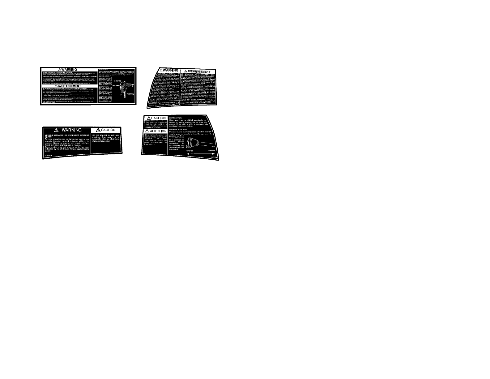
NOTE: Illustration of shift pattern may vary. Your model may differ.
VEHICLE CAPABLE OF EXCESSIVE REVERSE SPEED!
Reverse operation can be dangerous even at low speeds. Steering control
becomes difficult in reverse. Misuse of reverse can result in injury. Avoid
turning at sharp angles in reverse.
Transmission may not always be in the gear indicated by the shift lever. Always apply throttle slowly.
On machines with reverse it is especially important to maintain track tension
as specified in the owner’s manual. If specified track tension is not maintained severe damage to the machine may occur, which can result in loss of
vehicle control. Loss of vehicle control can result in severe personal injury or
death.
For More Info: See Operator’s Safety and Maintenance Manual supplied
with reverse kit.
SHIFT PATTERN
Make sure lever is shifted completely to forward or reverse position. Do not
force into reverse. If not able to shift to reverse, apply throttle gently to move
vehicle. CAUTION: Do not attempt to shift until machine has come to a
complete stop or chaincase damage may occur.
8
Page 14
SAFETY WARNING AND OPERATION DECALS
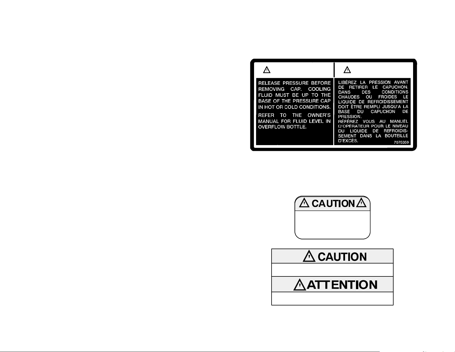
Some Liquid Cooled Models
CAUTION
Release pressure before removing cap. Cooling fluid must be
up to the base of the pressure cap in hot or cold conditions.
Refer to the Owner’s Manual for fluid level in overflow bottle.
Do not operate above 40 mph with
hood to air box foam removed or
engine failure will result.
ATTENTION
DO NOT OPERATE WITH INTAKE SILENCER
REMOVED.
NE PAS OPERER LORSQUE LE SILENCIEUX
DE LA PRISE D’AIR EST ENLEVE.
9
Page 15
OPERATION WARNINGS
Before Starting The Engine
Read and Understand Your Owner ’s Manual
Read the Owner’s Manual completely now, and re-read it occasionally. We have
attempted to provide you with as much information as possible to alert you to the
safety requirements of snowmobiling.
Check Throttle and Brake for Proper Operation
The throttleandbrake are the primary controlsof your snowmobile. If eithershould
malfunction, a serious loss of control could result.
When checking the throttle, make sure the control lever will compress evenly and
smoothly. When the lever is released, it should immediately return to the idle position without binding or hesitation. If the throttle does not function smoothly, do not
attempt to start the engine. Have the throttle serviced before starting the engine.
The need for a properly functioning brake is vital. This snowmobile is equipped
with the highest quality brake system available. The brake must be checked for
correct operation before starting the engine. See page 13 for details.
Check for Proper Operation of Steering System
Check for proper operation of the steering system by manually turning the skis
completely to the right and to the left. If difficulty is encountered, check for ice and
snow buildup which may be obstructing the steering linkage. Make certain all
greasable components are properly lubricated.
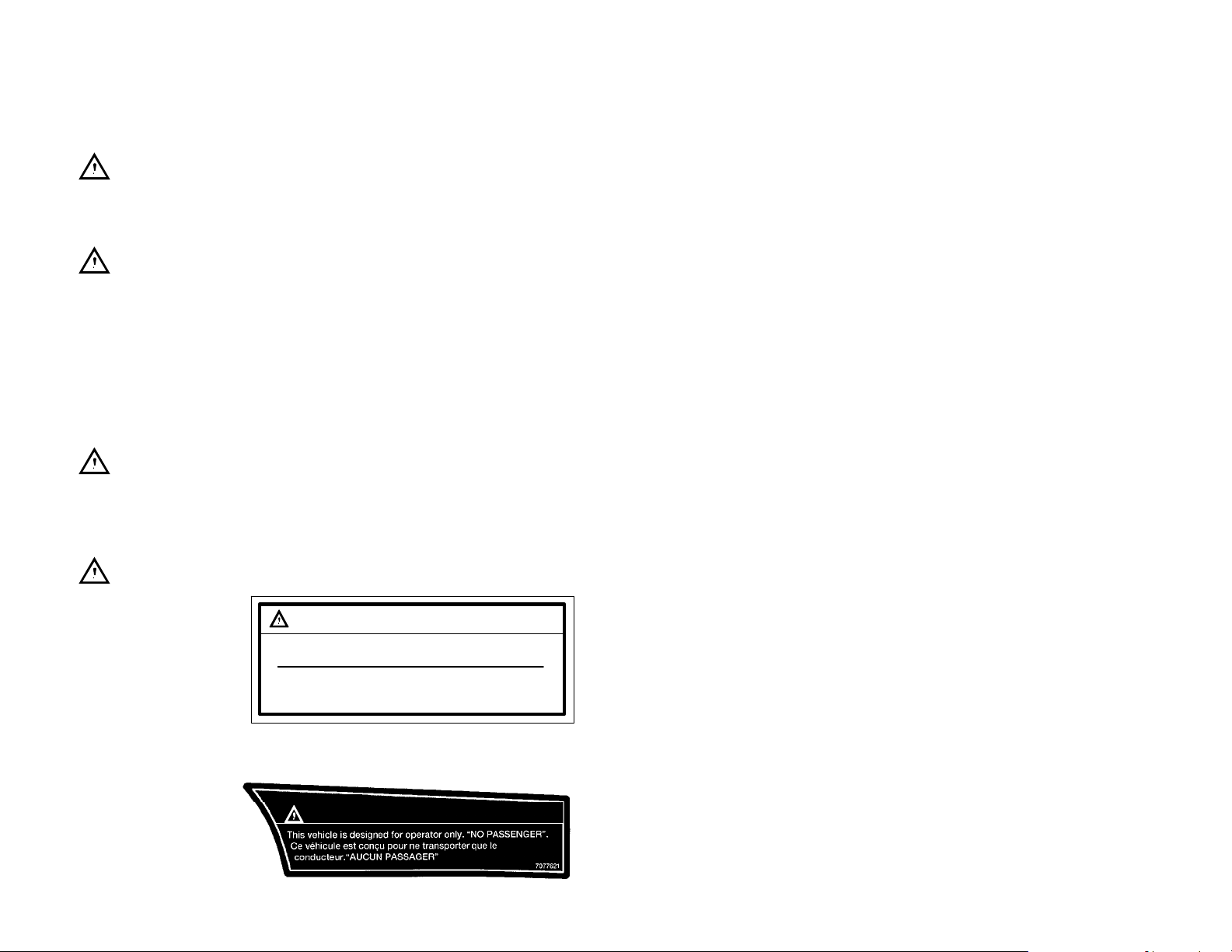
Single Rider Snowmobiles
Some Polaris snowmobile models are designed for a single occupant only. A decal on
the console of these
models indicates single
occupant operation.
10
W ARNING/AVERTISSEMENT
This vehicle is designed for operator only.
Ce vehicule est concu pour ne transporter
“NO PASSENGER”
que le conducteur.
“AUCUN PASSAGER”
OR
W ARNING/AVERTISSEMENT
Page 16
OPERATION WARNINGS
Driving 2-Up
When operating a 2-Up machine with a passenger, the driver should be aware that
more space will be required to make turns, and a longer distance will be necessary
for stopping. Lower speeds should be observed whenever riding 2-Up.
CAUTION: Always make certain the passenger remains seated behind the driver,
facing forward, with both feet placed firmly on the running boards. Reduce operating speed and be particularly careful to avoid “jumping” your snowmobile.
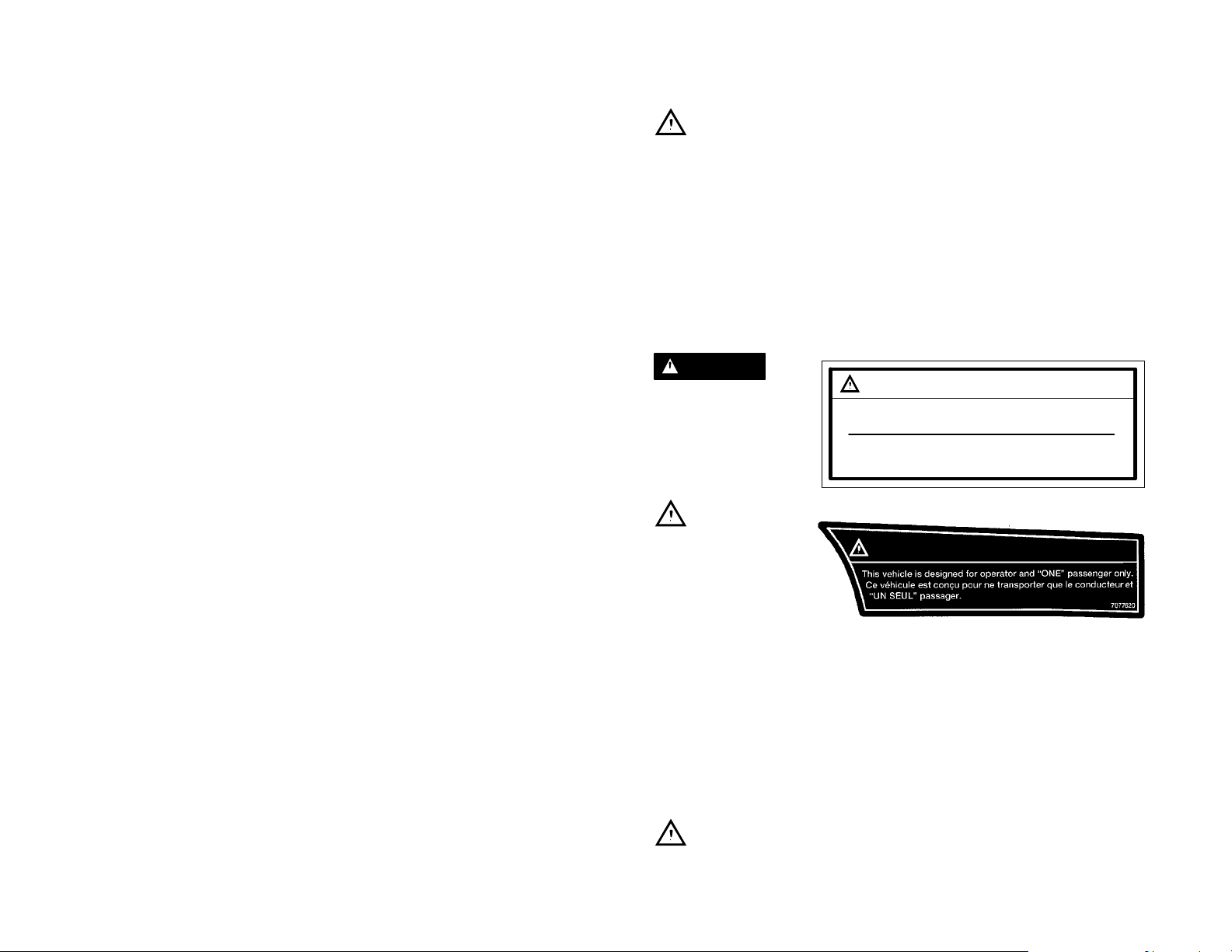
Some Polaris snowmobile models are designed for two occupants. A decal on the
hood of these models indicates that the vehicle is designed for one operator and
one passenger only. Machines designated as double occupant should never be
operated with more than two people on board. When traveling with a passenger
aboard, it is the driver’s responsibility to operate the machine in a safe manner.
Remember that control becomes more difficult with two people on board. Reduce
speeds to retain control!
WARNING
Use of a backrest can hinder operator weight shifting. This may affect control of this rider-active
vehicle in certain extreme
driving situations.
W ARNING/AVERTISSEMENT
This vehicle is designed for operator and
“ONE” passenger only.
Ce vehicule est concu pour ne transporter
que le conducteur et “UN SEUL” passager.
Track
or
Inspection
Driving at wide-open
throttle for extended periods of time in marginal lubrication could severely
damage track rods, break
track edges, and cause
other track damage. Examples of marginal lubrication would include lakes without snow cover, icy trails
and no-snow conditions.
Always inspect for damage before using the vehicle. Use of traction products such
as studs, ice growsers, paddles, etc. will increase the possibility of track damage
and/or failure. Operating the snowmobile with a damaged track will increase the
possibility of track damage and/or failure, which could cause loss of control
resulting in severe injury or death.
NOTE: Track damage or failure caused by operation on ice or poor lubrication
conditions will void the track warranty.
W ARNING/AVERTISSEMENT
Do Not Operate Engine With Intake Silencer or Filter Removed
When operatingengine with intakesilenceror filterremoved,damage to theengine
may occur.
11
Page 17

OPERATION WARNINGS
Stay Clear of Track
During warm-up and operation, stand clear of the rotating track. Do not use too
much throttle during warm-up or when track is free hanging. Entanglement and
serious injury or death may result.
Do Not Operate Engine With Clutch Guard Removed
The clutch guard is designed to protect the operator from metal parts in the event
the clutch should fail. Although the chance of failure is extremely remote, do not
defeat the purpose of the guard by removing it. It is provided for your safety.
Never Run Engine With Drive Belt Removed
Operation of the engine with the belt removed can result in serious over-speed
condition. Any servicing which requires operation without a belt must be done by
your dealer.
Never Service Clutches Yourself - See Your Dealer
The clutch is a complex mechanism which operates at high rotational speeds.
Each clutch is dynamically balanced before installation. Any tampering by the
owner may disrupt this precision balancing and create an unstable condition.
Seat Back/Cargo Carrier
Do not sit on seat back or cargo area. Do not exceed carrier and rack weight limits.
Cargo load affects machine steering response.
Disabled Operators
Safe operation of this rider-active vehicle requires good judgement and physical
skills. Persons with cognitive or physical disabilities who operate this vehicle have
an increased risk of overturnsand loss of control whichcouldresultin serious injury
or death.
12
Page 18
OPERATION WARNINGS
Hydraulic Brakes
The need for a properly functioning brake is vital. Polaris snowmobiles are
equipped with the highest quality hydraulic disc brake system available. The following items must be checked each time before startingthe engine to assure proper operation.
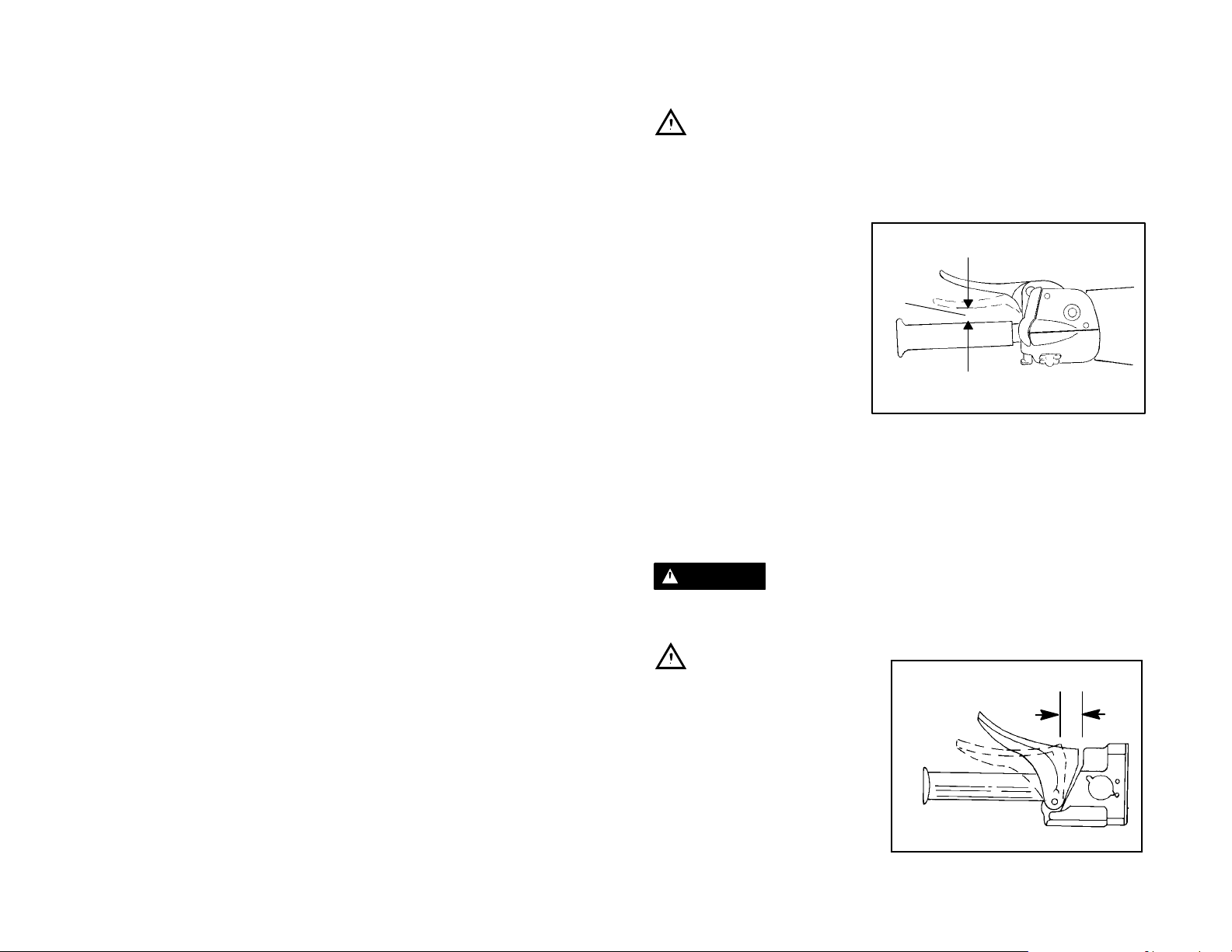
Brake Lever Travel
When the brake handle is depressed (A) , it should move no
closer than 1/2″ (1.3 cm) from the
handgrip. Excessive travel indicates low fluidlevelorair in thehydraulic system. If the lever travel
is excessive, refer to the brake
bleeding information on page 69.
Lever Feel
A hydraulic system multiplies the force of your hand squeeze on the brake lever.
Proper operation depends upon an adequate air and moisture-free supply of hydraulic brake fluid in the system. If the brake lever feels “spongy” when squeezed,
the level and condition of the fluid must be checked; as well as checking for the
presence of air in the fluid system. Refer to page 69 for more information orcontact
your dealer for service. Replace brake fluid at least every two years with Polaris
DOT 3 high temperature brake fluid. All DOT 3 brake fluid is not alike. We recommend the use of Polaris brake fluid (PN 2870990).
A
WARNING
Continued abusive brake application with a “spongy” brake condition may cause
a complete loss of brakes; which could result in severe injury or death.
Mechanical Brakes
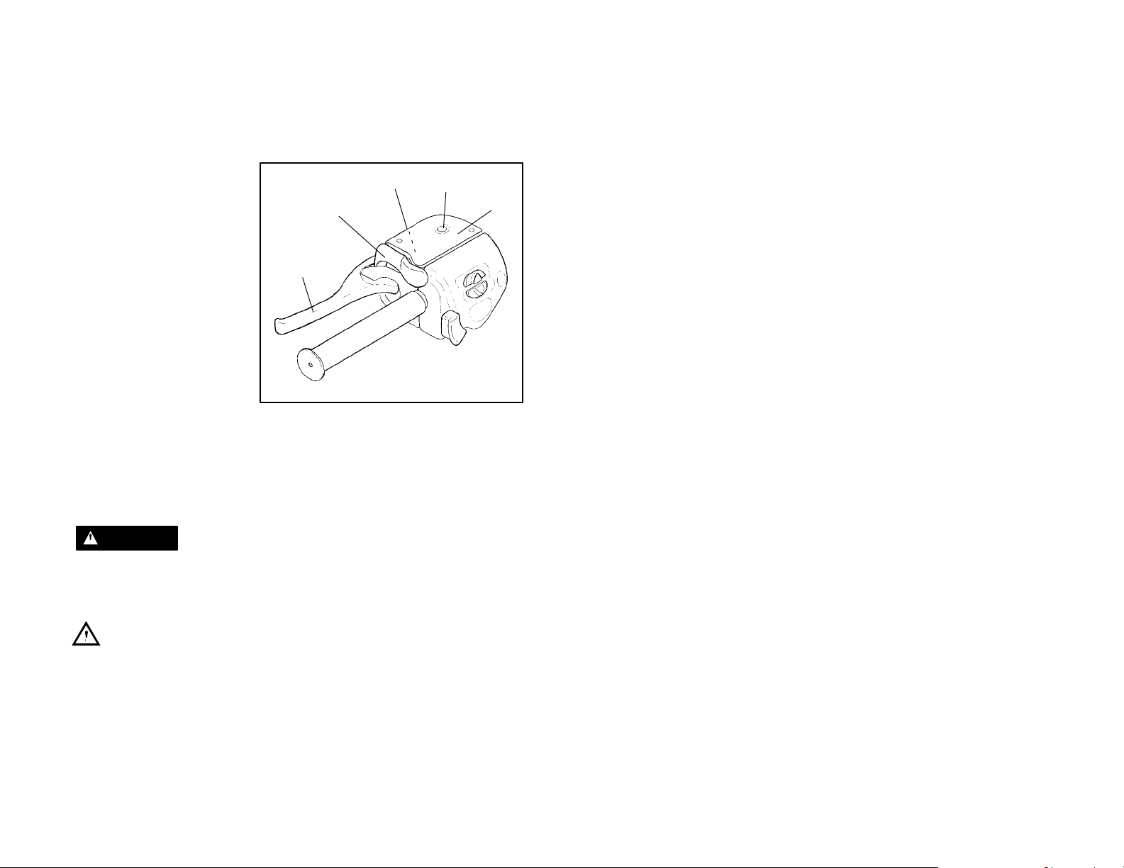
Brake Lever Travel
Measure the clearance between the
lever and brake block. Inspection
should be made with the lever firmly
depressed. Distance B should be no
more than 3/4″ (1.9 cm).
Excessive travel indicates a need to
adjust the brake cable adjuster. Refer to the mechanical brake adjustment information on page 72.
B
13
Page 19
OPERATION WARNINGS
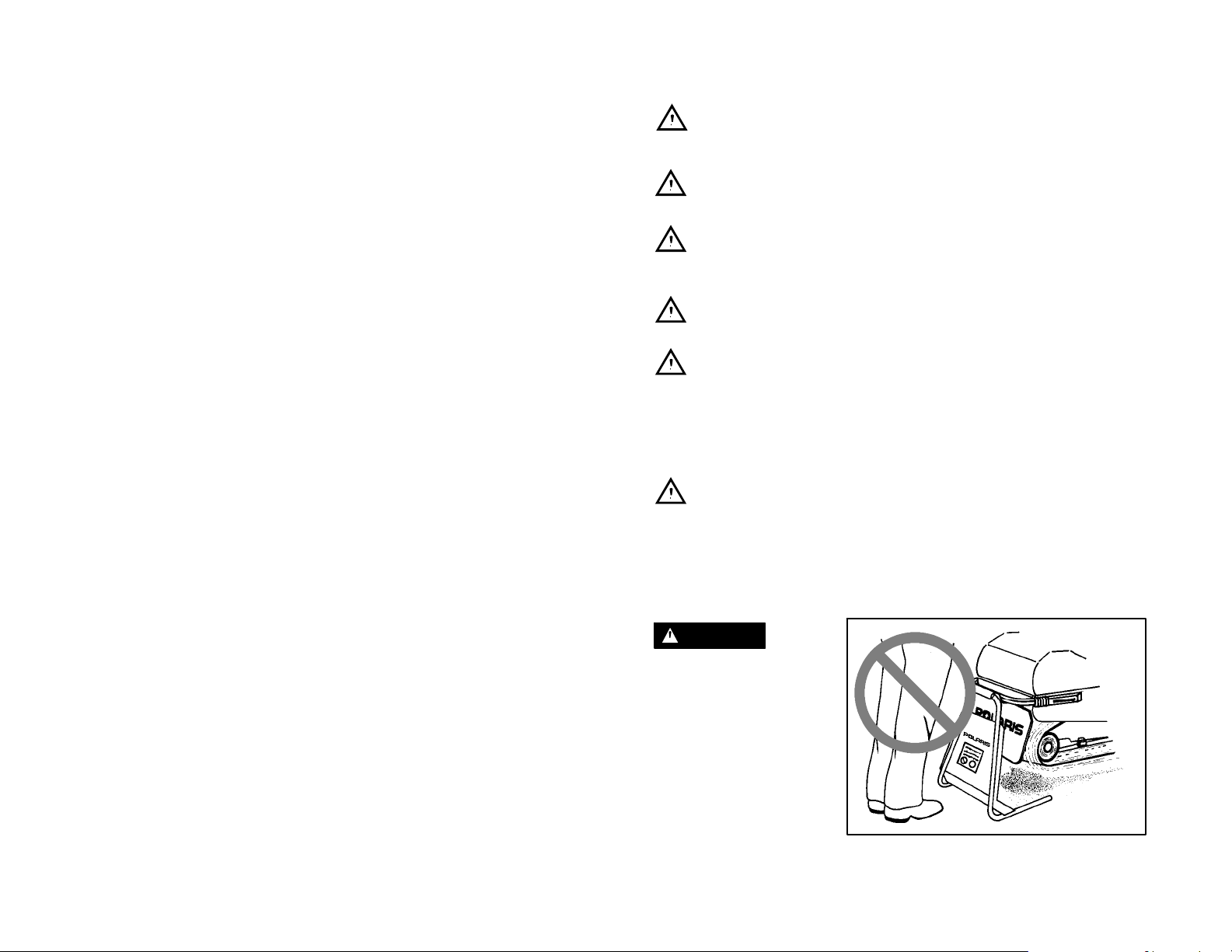
Park Brake Lever Lock
1. Brake Handle
2. Park Brake Lever Lock
(Not all models are
equipped with a park
brake)
3. Master Cylinder
Reservoir
4. Master Cylinder Cover
5. Fluid Level Indicator
Your snowmobile has a brake
brake lever lock. It is located
over the brake lever. Use the
brake lever lock only when you
want the machine to remain
stationary (e.g. when parked
on an incline) for a period of
five minutes or less. To apply
lock, squeeze brake handle
and push forward on brake lever lock. Hold lock forward and release brake handle.
To release lock, squeeze brake handle until lever returns to the unlock position.
The park brake light on the console will be lit when the park brake lever lock is set
and the engine is running. It is also lit when the service brake is in use. If the park
brake light does not come on when park brake or service brake is in use, have it
serviced by your dealer.
2
1
3
5
4
WARNING
If the park brake lever lock is left partially or entirelyengaged while riding the snowmobile, it could cause overheating of the brakes which could result in damage to
the brake caliper. In extreme cases it could cause a fire which could result in serious injury or death.
Check to See That the Hood is Securely Latched
The hood of the snowmobile protects the operator frommoving partsaswellasaiding in sound emission control and various other functions. Under no circum-
stances should your snowmobile be operated with the hood open or removed.
14
Page 20
OPERATION WARNINGS
Auxiliary Shut-Off Switch
Check auxiliary shut-off switch for proper operation. Push down to stop engine.
Pull up to release and start engine.
Tether Switch (accessory on all models)
Check tether switch for proper operation.
Remove Ignition Key
Don’t tempt anyone to steal or ride your snowmobile without permission by leaving
the key in the ignition.
Lighting Check
Check headlight high and low beam, taillight and brake light for normal operation.
Check Surroundings to Verify Clear Operating Area
It is most important to assure yourself that you have a clear area all around your
snowmobile, including an area clear of bystanders. Remember that the possibility
always exists of some sideways vehicle movement, or a little more throttle than intended; or debris may be thrown by the track. If you are assured of a clear area
surrounding you before you start, you can devote your full attention to operating
the snowmobile.
Be Seated and in Position to Control the Vehicle
Improper operator position on the snowmobile can be the source of serious injury.
Remember that operating a snowmobile does require skill and balance for proper
control, and an improper position can seriously reduce your ability to control your
snowmobile. The style of positioning will vary from person to person as they become more skilled; but under most conditions the proper position is to be seated,
feet on the running boards, and in a comfortable position for proper throttle,brake,
and steering control.
WARNING
Your snowmobile is propelled by a revolving track
which must be partially exposed for proper operation.
Serious injuries may be
caused by operator carelessness resulting in hands,
feet, or clothing becoming
entangled in the track. Be
alert. Remember, being
properly seated keeps you
clear of the track.
Never hold the snowmobile up or stand behind it while warming up the track. A
loose track or flying debris could cause serious personal injury or death.
15
Page 21
OPERATION WARNINGS
Stop Engine Before Attempting Adjustments
WARNING
The snowmobile engine compartment contains moving parts. Shields and guards
have been provided for your safety, but it is still possible to carelessly get your
hands or fingers into a moving belt or a rotating shaft. For this reason never attempt
adjustments with the engine running. Serious personal injuries can result. The
proper method is to turn off the ignition, raise the hood, make the adjustment, secure shields and guards, secure the hood, and then re-start the engine to check
its operation. The same is true of track alignment. If the track must be re-aligned,
it is recommended that this service be performed by your dealer.
Always Wear Clothing Designed f or Snowmobiling
Clothing designed for snowmobiling is warm, comfortable and safe.
WARNING
Always wear an approved helmet
and eye protection. Don’t wear
loose clothing or long scarves because they can easily become entangled in moving parts. Also, be
aware of the weather forecast and
especially the wind chill. A table is
provided on page 19 for your reference. Be prepared. Be warm and
comfortable.
Know the Limitations of the Machine and Your Skills as a
Driver
D Observe state and local laws governing snowmobile operation. They have
been established for your protection.
D Traveling at night requires extra caution. Check both headlight and taillight to
ensure proper operation. Do not “over-drive”your headlight beam. A good rule
to follow is to be able to bring your machine to a stop in the distance illuminated
by the headlight. High speed driving at night is dangerous and unwise, and
could result in severe personal injury or death.
D Be courteous to oncoming traffic by dimming your headlights and lowering your
vehicle speed. Your snowmobile is equipped with a high output head lamp system that can cause discomfort to operators of oncoming vehicles if the headlight
is not dimmed.
16
Page 22
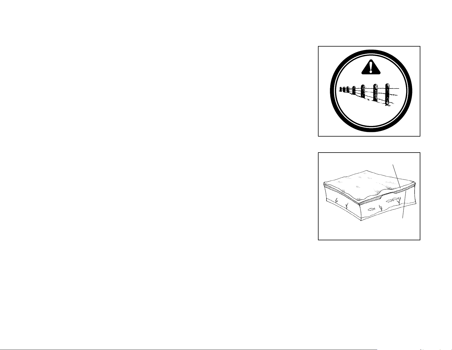
D Wire fences are a serious
hazard. Unless you are thoroughly familiar with an area,
you should always be on the
alert for fences. Single
strands are especially dangerous, since there can be a
great distance between
posts. Guy wires on utility
poles are also difficult to distinguish. Reduce speed
when traveling near poles,
posts, or other obstacles. Be
especially alert if y ou are
snowmobiling after dark.
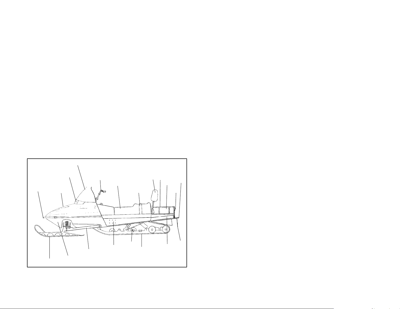
D When travelling on lakes and
streams that are strange to
you, always check with local
residents or authorities for
general information on conditions. Thin ice, open water,
and snowmobiles are not
compatible. Before riding
your machine on a frozen
body of water,be sure that the
ice is thick enough to support
the machine and its operator
as well as the force created by
a moving vehicle. Variances
in snow depth and/or water
currents can result in uneven
ice thickness. Use common
sense and good judgment at
all times as drowning may result ifyou and the snowmobile
break through the ice.
OPERATION WARNINGS
Snow
Ice
17
Page 23

OPERATION WARNINGS
D Remember, the sound of your ma-
chine will drown out the sound of
approaching vehicles. Look ahead,
behind, and to the sides before turning or crossing railroad crossings or
highways. Steep embankments
may also hide your view. Always
leave yourself a way out. Make
sure the way is clear before you
cross railroads and other roads and
highways.
D Drive defensively when traveling in a group of snowmobiles to avoid accidents.
Don’t tailgate. Allow ample stopping distances.
D Always be alert and pay attention to the trail ahead of you. Multiplying speed
(MPH) by 1.5 will equal the approximate number of feet per second your machine travels. If your speed is 40 MPH, your machine is travelling approximately
60 feet per second. This means that if you look back for only two seconds, your
machine will travel about 120 feet. If your speed is 60 MPH, your machine will
travel approximately 180 feet in two seconds.
D When teaching inexperienced operators to ride, set up a nearby predetermined
course. Make sure they know how to drive and control the snowmobile before
you allow them to make longer distance runs. Teach them proper snowmobile
courtesy. Enroll them in a driver’s training and safety course sponsored by a
local or state organization.
18
Page 24

OPERATION WARNINGS
W
ind
S
d
i
40MPHHave
ClothedPerson
)
W
ind
S
d
i
70KPHHave
ClothedPerson
)
Windchill/Temperature Charts
The following information is provided as a guide to determine what temperatures
are dangerous when riding your snowmobile.
WIND CHILL CHART (°F)
Estimated
pee
n
MPH
Calm 50 40 30 20 10 0 -10 -20 -30 -40 -50 -60
5 48 37 27 16 6 -5 -15 -26 -36 -47 -- 5 7 -68
10 40 28 16 4 -9 -21 -33 -46 -58 -70 -83 -95
15 36 22 9 -5 -18 -36 -45 -58 -72 -85 -99 -112
20 32 18 4 -10 -25 -39 -53 -67 -82 -96 -110 -124
25 30 16 0 -15 -29 -44 -59 -74 -88 -104 -118 -133
30 28 13 -2 -18 -33 -48 -63 -79 -94 -109 -125 -140
35 27 11 -4 -20 -35 -49 -67 -82 -98 -113 -129 -145
40 26 10 -6 -21 -37 -53 -69 -85 -100 -116 -132 -148
Wind Speeds
Greater Than
40 MPH Have
Little Added
Effect
50 40 30 20 10 0 -10 -20 -30 -40 -50 -60
Little Danger
(For Properly
Clothed Person)
Actual Thermometer Reading (°F)
Equivalent Temperature (°F)
Increasing
Danger
Danger From Freezing of Exposed Flesh
Great
Danger
WIND CHILL CHART (°C)
Estimated
pee
n
KPH
0 5 0 -5 -10 -15 -20 -25 -30 -35 -40
10 1 -4 -11 -16 -22 -27 -33 -38 -45 -50
20 -4 -9 -17 -23 -29 -36 -42 -48 -54 -61
30 -7 -13 -21 -28 -35 -42 -48 -55 -63 -69
40 -9 -16 -24 -32 -39 -47 -53 -61 -69 -76
50 -11 -18 -26 -34 -41 -49 -57 -64 -73 -80
60 -12 -19 -27 -35 -43 -51 -59 -66 -75 -82
70 -13 -20 -28 -36 -44 -52 -60 -68 -76 -84
Wind Speeds
Greater Than
70 KPH Have
Little Added
Effect
5 0 -5 -10 -15 -20 -25 -30 -35 -40
Little Danger
(For Properly
Clothed Person)
Actual Thermometer Reading (°C)
Equivalent Temperature (°C)
Increasing
Danger
Danger From Freezing of Exposed Flesh
Great
Danger
19
Page 25

OPERATION WARNINGS
Cold Weather Driveaway
Whenever the machine has been parked for some length of time, especially overnight, always shake loose the skis and track before attempting to put the machine
into motion. The throttle should always be opened with enough authority to put the
machine into motion, staying within safety limits and with respect to a passenger,
on a two passenger machine.
Powder Snow Operation
Your Polaris is designed to operate best on snow. Maneuverability is attained by
the steering, skis, and the shifting of your body weight. Maximum control will be
attained by shifting body weight. Maneuverability will change for lighter operators
or machines carrying a load or a passenger where allowed.
CAUTION: Do not operate for prolongedperiods on blacktop,
gravel, or glare ice.
It is essential that your machine be operated under conditionswith adequate snow
cover, as snow provides the only lubrication for the power slide suspension and,
on liquid cooled models, coolingfortheengine. Failure to do so will result in excessive wear and damage to the slide rail and track and/or engine.
If the machine becomes stuck in snow, free the running board area, and step down
the snow in front of the machine so that when the throttle is opened the machine
will be able to climb up and over. The operator can then mount the machine and
continue.
WARNING: Snow and ice buildup in the underhood area can
cause interference with the steering function.
Before driving, be sure that ice and snow are not interfering with full left and right
steeringby manuallyturning the skis to the left and right. Ifdifficulty is encountered,
check for ice and snow buildup which may be obstructing the steering linkage.
Snow screen and bib kits are available through your dealer to help reduce snow
and ice buildup.
NOTE: The ability of the machine to travel in adverse conditions will improve as
the operator gains experience.
20
Page 26

OPERATION WARNINGS
Hard Packed Snow
WARNING
Steering and braking control are substantially reduced under
packed snow or icy conditions.
Excessive shifting of operator body weight when turning on hard packed snow or
slippery surfaces can result in loss of vehicle control and serious injury. Reduce
speed as required to maintain control under these conditions.
Ice
It is dangerous to operate on ice or under slippery conditions. If ice or slip-
speeds no faster than a walk. Never attempt an abrupt change of direction on a
slippery surface. The chance of “spin-out” increases under these conditions.
Before riding your snowmobile on a frozen body of water, be sure that the ice is
thick enough to support the machine and its occupant(s) as well as the force that
is created by a moving vehicle. Severe injury or death can result if the snowmobile
and/or its occupant(s) break through the ice.
pery conditions are unavoidable, use extreme caution and operate at
21
Page 27

OPERATION WARNINGS
Hilly Terrain
Exercise caution and good judgement when travelling in hilly terrain.
Crossing a Slope (Sidehilling)
WARNING
Sidehilling can be very dangerous and is not recommended for inexperienced
snowmobilers.
Crossing the face of a slope (sidehilling) requires the operator to position his/her
weight in order to maintain proper balance. Kneel with the knee of the downhill leg
on the seat and the foot of the uphill leg on the running board. This position makes
it easier to shift your weight as needed. As you travel across the slope, lean uphill
to position your weight on the uphill side.
22
Page 28

OPERATION WARNINGS
Riding Uphill
Hill climbing may be accomplished by using one of two methods, depending upon
the steepness of the hill.
Sidehilling may be used if there are few obstacles on the hill. The operator should
assume a kneeling position (as in Sidehilling), keeping body weight on the uphill
side at all times. Maintaining a steady, s afe speed, approach the hill at an angle,
continuing as far as possible in this direction; then switch to the opposite angle and
riding position.
The direct climb method requires extreme caution. The operator should assume
a standing position with body weight kept low and forward, accelerating before the
start of the climb and then releasing throttle pressure enough to prevent track slippage.
In either type of climb, the operator must slow down when reaching the crest of the
hill. Be prepared to react to obstacles, sharp drops, or other people or vehicles
which may be on the other side of the hill.
If you are unable to continue up a hill, turn the machine downhill before it
in so the machine won’t roll back down the hill. Stop the engine and set the parking
brake (if equipped). Keeping away from the downhill side of the machine, pull the
rear of the snowmobile around, pointing the machine back downhill. Once the
snowmobileis pointeddownhill, mount the machine,restart theengine,releasethe
parking brake, and descend the hill.
Riding Downhill
When riding downhill, keep speed at a minimum. It is important to apply just
enough throttletokeep the clutchengaged whiledescendingthehill. This will allow
use of the engine’s compression to help slow the machine, and keep the snowmobile from rolling freely downhill.
loses momentum. If this is not possible, spin the track just enough to dig
WARNING
Use extreme caution when applying the brake during a descent. Excessive braking will cause the track to lock, resulting in loss of control.
23
Page 29

OPERATION WARNINGS
Responsible Driving
If you operate the snowmobile improperly, you will cause situations which will exceed your driving skills. Each snowmobile handles differently, and even if you are
a seasoned driver, it is strongly recommended that you spend some time getting
the feel for this particular machine before attempting ambitious maneuvers. If you
are new to snowmobiling, take enough time to acquaint yourself with the machine
and what it will and won’t do under various conditions.
Acquire a feel for your machine before attempting ambitious maneuvers.
The snowmobile depends on your body position for proper balance in
executing turns, traversing hills, etc. It’s best to start on a smooth level area to begin building your operating experience.
Before you let someone else use your snowmobile, be sure you know the
extent of their operating skills. Check to see if they have taken a snowmobile safety course and have an operator’s certificate. For their protection, as well
as yours, make sure they take a snowmobile safety course. Everyone can benefit
from the course.
Don’t “jump” your snowmobile. Jumping can injure your back because of
been designed and constructed to give you protection, but they do have limits.
Your snowmobile is not intended for this kind of use.
spinal compression. The seat and suspension of your snowmobile have
24
Page 30

PRESERVATION OF THE ENVIRONMENT
We recommend that you drive your snowmobile with consideration for the protection and preservation of our environment.
Noise Level
Probably the most publicizedsubjectwithregard to snowmobiles is noise. The Society of Automotive Engineers (SAE), which is the standard-setting body for snowmobiles,has recommendedthatsnowmobilesconform to prescribed sound levels.
Your Polaris snowmobile has been engineered to conform to these SAE standards.
In order to be meaningful,allregulations requirethecooperationofthe snowmobile
driver. Muffling systems, designed to reduce noise levels, should not be altered
or removed. Snowmobile drivers must be aware that they have a public responsibilityto operate their snowmobiles with concern for others. As a snowmobile operator you may not realize the sound of your snowmobile may annoy non-snowmobilers. We are attempting to do our part through the manufacture of quieter
machines, and we also ask your help in the effort to further reduce the impact of
noise.
Air Pollution
As a part of Polaris’ plan for the snowmobile’s compatibility within the environment,
our engineers are investigating ways to reduce emission levels of two-stroke engines. We expect our efforts to lead to the reduction of potential air pollution.
In addition to technological research, we also suggest that governmental agencies, manufacturers, distributors, dealers, ecologists, and other interested parties
work together to develop data on environmental topics. We will continue to participate in this type of study so that someday we may find the answers to these difficult
issues.
Environmental Protection
As part of the continuing environmental education campaign, we are encouraging
state and provincial governments across the snowbelt to adopt rigorous safety
training programs which also encourage protectionof ourenvironment,wildlifeand
vegetation. Snowmobile clubs and other organizations are working together to
protect our environment. It is very important that we encourage them as well as
become actively involved ourselves.
Respect your snowmobile;
respect your environment;
and you will earn
the respect of everyone.
25
Page 31
IDENTIFICATION AND SPECIFICATIONS
Vehicle Nomenclature
Refer to illustrations on following pages. NOTE: Illustrations are a general representation. Your model may differ.
1. Hood 13. Suspension
2. Headlight 14. Nosepan
3. Windshield 15. Trailing Arm
4. Handlebar 16. Skis
5. Seat 17. Front Bumper
6. Storage/Rear 18. Console
7. Taillights 19. Vehicle I.D. Number (Right Side)
8. Backrest 20. Rear Bumper
9. Tunnel Extension 21. Passenger Hand Hold
10. Passenger Hand Hold Strap 22. Lifting Hand Hold
11. Track 23. Snow Flap
24. Mountain Bar
Vehicle Nomenclature, Cont.
3
26
17
16
2
1
14
15
4
5
10
19
13
11
8
22
20
6
7
23
9
Page 32

IDENTIFICATION AND SPECIFICATIONS
Vehicle Nomenclature, Cont.
3
2
1
22
17
18
4
5
6
8
20
16
16
17
14
14
13
10
5
13
11
8
11
18
18
19
4
19
15
3
2
1
15
23
22
6
7
9
23
27
Page 33

IDENTIFICATION AND SPECIFICATIONS
Vehicle Nomenclature, Cont.
17
16
3
2
1
14
15
24
19
5
4
6
7
20
23
13
11
28
Page 34

IDENTIFICATION AND SPECIFICATIONS
Controls and Instruments
General Representations
Your Model May Differ
1. Headlight Dimmer Switch (2
Position)
2. Fuel Filler Cap/Gas Gauge
3. Auxiliary Shut-Off Switch
(Push/Pull). Operation found
on page 40.
4. Throttle Control
5. Recoil Starter Handle
6. Choke Control
7. Ignition Switch
8. Tachometer (may include indicator
/ warning lights)
9. Speedometer (may include indicator / warning lights)
10. Brake Lever
11. Low Oil Warning,Brake Light,
High Beam, Temp, premium fuel
options
12. Accessory Indicators
13. Safety Decals
14. Hood Hold Down
15. Handlebar Grip Warmer Switch
16. Thumbwarmer Switch
17. Thumbwarmer/Handwarmer
Switch
18. Reverse Lever
19. Fuel Gauge
20. Temperature Light
21. Tether Switch
22. Power Plug
23. Electric Shock Absorber Gauge
10
16
1
10
6
15
1
10
17
1
20
9
3
13
7
2
12
20
11
19
9
16
2
9
2
7
21
8
15
7
6
8
22
6
4
14
13
3
4
23
13
3
4
5
18
29
Page 35

IDENTIFICATION AND SPECIFICATIONS
Backrest
1. Backrest Cushion Adjuster
2. Backrest Adjuster Cable
3. Grab Bar Adjustment Knob
4. Passenger Handwarmer Switch
5. Wind Deflector
6. Backrest Adjustment Lever
7. Passenger Hand Hold
5
7
1
2
4
6
3
30
Page 36

OPERATION
Carburetion
Proper carburetor adjustment is critical, since a mixture too lean (too much air, too
little fuel) will result in overheating of the combustion chamber causing pre-ignition
of the fuel. This results in piston burning, bearing failure, or complete engine failure. A lean mixture can be the result of fuel line restrictions, foreign matter in the
carburetor, clogged fuel filter, etc.
A mixture too rich (too much fuel, too little air) is also unfavorable because it can
foul plugs and cause generally poor engine performance.
All carburetors have been pre-set at the factory for adequate fuel supply. Higher
altitude operation may require different adjustment and settings.
RMK models are pre-set to operate at altitudes of 6000-9000 feet above sea level.
WARNING
Carburetoradjustments must be performed by your dealer, since mistakes can result in possible operator safety hazards as well as serious engine damage.
Remember, correct setup provides engine RPM within its given power band at full
throttle settings and also provides maximum efficiency and operation at all other
throttle openings. Your dealer has the training and tools required to perform any
adjustments for you.
WARNING
Engine damage may result if jetting or clutching is wrong. Never service clutches
yourself. See your dealer.
Drive System
1. Engine
2. Torque Converter
(Drive Clutch)
3. Driven Clutch
4. Drive Belt
(Neutral Position)
5. Drive Belt
(Full Upshift Position)
6. Upper Chaincase
Sprocket
7. Chain
8. Lower Chaincase
Sprocket
9. Chaincase Oil Level
10. Drive Shaft
11. Tr ac k
3
4
1
5
2
10
11
6
7
8
9
31
Page 37

OPERATION
Lubrication
The fuel and oil which enter the engine through the fuel and oil injection systems
provide the only source of engine lubrication, and must be of the highest quality.
You can understand the importance of proper lubrication when you realize that at
6000 RPM the crankshaft is rotating 100 revolutions per second.
Premium 2-Cycle Lubricant
The only oil recommended for this fuel system is Polaris brand oil. CAUTION: En gine warranty coverage may become void if other brands are substituted.
Polaris Premium Gold Synthetic Lubricant is the most advanced formulation of oil
available for today’s 2-cycle engines. Over twenty months of lab and field tests
have resulted in a new generation of 2-cycle lubricant. Polaris Premium 2-Cycle
Lubricant addresses the problem of lower quality fuel; keeping ring grooves cleaner with less ring sticking and providing improved overall engine cleanliness. With
new generation lubricity technology, it excels in meeting the lubricity demands of
today’sfaster,more precisely engineered 2-cycle engines. Itis theoptimum oil recommended for liquid 2-cycle engines and performs well in all air cooled 2-cycle engines. We believe this oil is the best product available in the market today, and
strongly recommend its use in all of our products.
Never mix other brands of oil since they may be incompatible, resulting in sludge
formation, filter blockage and reduced cold weather flow rates.
Oil Injection System
The fuel-to-oil mix ratios are controlled by the oil pump and the movement of the
oil pump arm. The fuel-to-oilmix ratiocorresponds to the engine’s RPM and throttle
valve opening.
Always fill the oil reservoir when refueling.
NOTE: Mix two pints of Polarisinjection oiltothefirst tankfulof gasoline. In addition
to the lubrication supplied by the injection system, this will ensure proper engine
break-in.
CAUTION:
Check the oil tank level often during the first tankful of fuel. If the oil level doesn’t
go down, contact your dealer immediately. Continue using premixed fuel until the
oil injection system can be inspected.
Low Oil Indicator Light
The low oil indicator light is standard on most models.
CAUTION:
When the low oil indicator light is on, it indicates that oil must be added before further operation of the snowmobile. Visually check the oil level in the bottle. The engine can be operated as long as oil is v isible in the oil tank. If oil is not visible, continued operation may cause severe engine damage.
32
Page 38

OPERATION
WARNING
Never mix brands of two cycle oil. Serious chemical reactions can occur, causing
injection system blockage resulting in severe engine damage and voiding of engine warranty.
CAUTION:
Always maintain the oil level in the oil tank above the low level line. The low oil indicator light will indicate when to add oil. However, the oil level should always be
checked when refueling. NOTE: In the illustration,
This is especially important when the machine is operated in mountainous terrain.
Maintaining the proper oil level will prevent system aeration and possible loss of
pumping action, which c ould result in engine damage.
NOTE: Always use a Polaris oil cap, never substitute. Your Polaris oil cap may
be vented to allow proper oil flow.
* indicates low oil level.
NOTE: Not all models
have a coolant bottle attached to the oil tank.
*
*
At low level mark add 1 U.S. quart.
*
33
Page 39

OPERATION
Fuel
WARNING
Gasoline is extremely flammable and explosive under certain conditions.
Always stop the engine and refuel outdoors or in a well ventilated area.
Do not smoke or allow open flames or sparks in or near the area where refueling is performed or where gasoline is stored.
Do not overfill the tank. Do not fill the tank neck.
If you get gasoline in your eyes or if you swallow gasoline, see your doctor
immediately.
If you spill gasoline on your skin or clothing, immediately wash it off with
soap and water and change clothing.
Never start the engine or let it run in an enclosed area. Gasoline powered
engine exhaust fumes are poisonous and can cause loss of consciousness and death in a short time.
34
WARNING
The engine exhaust from this
product contains chemicals
known to cause cancer, birth de-
fects or other reproductive harm.
Page 40

OPERATION
Fuel
The fuel used in the Polaris engine is as important to engine life and performance
as the lubricant used.
Most Polaris engines are designed to run on 87 octane non oxygenated or 89 octane oxygenated pump gasoline. There is a great deal of variability in the quality
of the 87 octane gasoline available across the country. We encourage the use of
premium fuel when possible. NOTE: XCR models require premium gasoline.
Consult your Owner’s Manual Supplement for specific minimum octane requirements.
Premium Fuel Switch
Some Polaris snowmobiles are
equipped with a key function that will
adjust the timing on the machine as
you change fuels.
Most high performance machines require the use of premium fuels. When
premiumfuelisnot available,thereis a
risk of engine damage when other
fuels are substituted.
When using fuels with a pump posted
octane rating of 91 or higher, turn the
key switch to “ON/PREM”. When the
engine is started a yellow “Premium
Fuel” light illuminates on the instrument panel. When the key is in this
position, the fuel must be a minimum
of 91 octane.
Premium Fuel Setting
Regular Fuel Setting
If you are uncertain about the quality or octane rating of the fuel you are using, turn
your key switch to “ON/REG”. The “Premium fuel” light will go out. This setting will
adjust the timing of your engine to run on fuels with 87 octane or higher. Polaris
does not recommend using fuel with lower than 87 octane.
Running your machine on “ON/REG” will protectyour engine from damage caused
by low octane fuels. It is very important to the life of your engine that you are aware
of and use this feature.
35
Page 41

OPERATION
Fuel Reserve Capacity
On equipped models, when the fuel gauge reads “RES”, there are approximately
2 gallons of fuel left in the tank.
Fuel System Deicers
If you are using non-oxygenated fuel, Polaris recommends the regular use of Isopropyl base fuel system deicer (Polaris PN 2870505). Add 1 to 2 ounces per gallon
(8-16 milliliters per liter) of gasoline to prevent engine damage resulting from fuel
system icing and lean mixtures. Never use deicers or additivesthatcontainme tha-
nol. Use only isopropyl fuel system deicers.
If using oxygenated fuel containing ethanol, additional alcohol deicers or water absorbing additives are not required and should not be used.
CAUTION:
Prolonged exposure to petroleumbased productsmay damage paint. Always protect painted surfaces when working with fuel.
It is recommended that plastic side panels be removed whenever servicing requires tipping the machine on its side for a period of fifteen minutes or more.
Tool Pouch Clip
Some Polaris snowmobiles are equipped
with a tool pouch clip which is located inside
of the flap on the back of the seat. Using this
clip will secure the tools, preventing them
from freely bouncing around during s nowmobile use.
Tool Pouch
36
Tool Clip
Page 42

OPERATION
Engine Break-In
No single action on your part is as important to long, trouble-free machine life as
proper break-infor a new or rebuiltengine. Familiarize yourself and others with the
following procedure for your Polaris snowmobile.
Premix the first tank of gasoline with one pint of Polaris injection oil for each 5 gallons of fuel. This, in addition to the lubrication supplied by the injection system, will
assure proper engine break-in. IMPORTANT: Before operatingwithunmixed fuel,
make sure oil is being drawn from the oil tank.
WARNING
D Never mix brands of two cycle oil. Serious chemical reactions can cause injec-
tion system blockage, resulting in s evere engine damage and voiding of engine
warranty. The only oil recommended for this system is Polaris injectionoil. This
oil has been specially formulated forall temperatures and has extreme cold flow
characteristics.
D Do not operate at prolonged full throttlefor the first threehoursof operation. Vary
the throttle openings and machine speeds. This will reduce friction on all close
fitting machined parts and allow them to break in slowly without damage.
D Avoid operating on ice or hard-packed surfaces, roads, etc. The absence of lu-
brication and cooling by snow will lead to overheating of the slide rail and track
resulting in premature wear and failure. Reduce speeds and frequently drive
into freshsnow to allow adequate cooling and polishing of the slide rail and track
surfaces.
D Drive with extra caution during the break-in period. Perform regular checks on
fluid levels, lines, and all important areas of the machine.
With a basic understanding of how the snowmobile works, and with close attention
paid to maintenance tips, you will be ready to ride. Keep in mind these recommendations as well as those covered throughout this manual.
37
Page 43

OPERATION
Pre-Starting
WARNING
Before starting the engine, always refer to all safety warnings pertaining to snowmobile operation. Never start your snowmobile without checking all components
to be sure of proper operation. See Operation Warnings beginning on page 10.
Important safety items include, but are not limited to:
D Throttle system
D Brake system
D Steering system
These systems must be checked each time before starting the engine. Incorrect
adjustments, damage, or excessive wear due to neglect could result in personal
injury and/or damage to the snowmobile.
Starting a Cold Engine (Manual Start)
1. Turn key to “On”.
2. Pull kill switch (shut-off switch) up to “run” position.
3. Flip choke toggle to “Full On” position.
4. Grasp starter handle and pull slowly until recoil engages; then pull to start.
CAUTION:
Do not pull the starter rope to its full extended position or allow it to snap back into
the housing as damage can result.
NOTE: Do not depress throttle until engine starts.
5. After engine starts, the choke toggle should be flipped to “Off” position. If the
engine slows or wants to s top, intermittent choking to the “Half On” position is
helpful.
Starting a Cold Engine (Electric Start)
1. Flip choke toggle to “Full On” position.
2. Pull kill switch (shut-off switch) up to “run” position.
3. Turn key to “Start” position and crank engine.
4. Afterenginestarts, release key to “On” positionandflipchoke toggleto“Off”. If
the engine slows or wants to stop, intermittent choking to the “Half On”position
is helpful.
NOTE: Do not depress throttle until engine starts.
38
Page 44

OPERATION
Starting a Warm Engine
1. Turn key to “On”.
2. Pull kill switch (shut-off switch) up to “run” position.
3. Grasp starter handle and pull slowly until recoil engages; then pull to start.
If the engine does not start on the first pull, slightly depress the throttle with your
left hand (no more than 1/4″ open), and pull the rope with your right hand. As soon
as the engine starts release the throttle.
CHOKE TOGGLE POSITIONS
Off or
Half On or
On or
39
Page 45

OPERATION
Auxiliary Engine Shut-Off Switch
To stop the engine in an emergency, push down on the auxiliary shut-off switch (A). This will
ground out the ignition and bring
the engine to a quick stop. To restart the engine the switch must
be pulled up to the “On” position.
A
Throttle Safety Switch
Test the throttle safety switch
system on a daily basis before
the machine is used.
While seated in a normal riding
position, and with the engine idling, hold the throttle lever pin
stationary by exerting pressure
on the pivot pin in the direction
shown in the illustration (B). Apply a slight amount of throttle
opening. A properly functioning
switch must shut down the engine.
B
The throttle safety switch is designed to stop the engine whenever all pressure is
removed from the throttle lever and the throttle cable or valves do not return to the
normal closed position.
WARNING
If the throttle safety switch does not shut off the engine in the event of a carburetor/
throttle system malfunction, immediately push down the auxiliary shut-off switch.
Do not start the engine until the malfunction has been corrected by your dealer.
If the snowmobile engine stops abruptly when the throttlelever is released, use the
following procedure.
1. Turn the ignition switch to “Off”.
2. Visually inspect the throttlecable and carburetor(s) to determine what caused
the safety switch to activate.
3. Test the throttle lever by compressing and releasing itseveraltimes. The lever
and cable must return to the idle position quickly and completely.
40
Page 46

OPERATION
WARNING
If the throttle lever does not work properly, do not start the engine.
4. If the throttle lever operatesproperly, turn the ignitionswitchon and go through
normal starting procedures.
5. If the engine does not start, take the snowmobile to an authorized Polaris
dealer for service.
If excessive play develops in the throttle cable, the safety switch may be activated,
preventing the engine from starting. Contact your dealer.
If the engine does not start, and throttle safety switch malfunction is suspected, returnthe machine to an authorized Polarisdealerfor service. If an emergency exists
and it is necessary to start the engine, the throttle safety switch and auxiliary shutoff switch may be disconnected from the wire harness.
WARNING
With the throttle safety switch and auxiliary shut-off switch disconnected, the ignition key s witch must be used to shut off the engine. Do not continue to operate the
machine with the throttle safety switch disconnected. Return the machine to an
authorized Polaris dealer for service as soon as possible.
41
Page 47

OPERATION
Emergency Stopping Procedures
The following chart lists methods for stopping the engine in the event of an emergency.
SYSTEM
Ignition Switch Interrupts ignition circuit All
Brake Slows drive shaft All
Choke Floods engine 1/2 throttle or less
Auxiliary Shut-Off Switch Interrupts ignition circuit All
Throttle Safety Switch Interrupts ignition circuit All
Tether Switch (Option) Interrupts ignition circuit All
Refer to page 40 for more information on the auxiliary shut-off and throttle safety
switches.
WHAT IT DOES THROTTLE
CONDITION
Emergency Starting Procedure
Your machine comes with a tool kit containing essential tools for emergency use.
In the event the recoil starter system should fail, take the emergency start strap
from the kit and proceed as follows:
1. Open clutch guard.
2. Push on the inner sheave
of the secondary clutch and
rotate clockwise slightly to
relieve belt tension. This
allows for easier starting.
3. Starting at one of the tower
struts, wind the strap
counterclockwise around
the clutch as shown.
WARNING
Do not wind the strap around your hand. Severe injury could result.
4. Pull the strap using a sharp, crisp pull so the strap comes free of the clutch.
CAUTION:
Keep all people clear of the snowmobile when using the emergency starting procedure.
42
Page 48
OPERATION
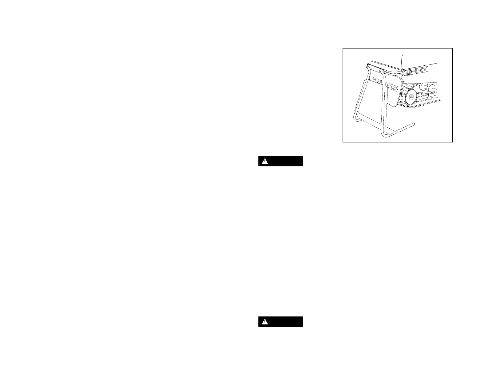
Pre-ride Warm Up
The following steps must be
taken to ensure proper warm
up of the engine, drive train and
track.
With the snowmobile securely
supported by the rear bumper,
and approximately 4″ (10 cm)
off the ground, use the following procedure.
1. Start the engine and allow
it to warm up two to three
minutes.
WARNING
Be sure the rear support is stable. Stand clear of the front of the machine and the
moving track. Never hold the snowmobile up or stand behind it while performing
this procedure. Do not use too much throttle during warm up or when track is freehanging. A loose track or flying debris could cause serious personal injury or
death.
2. Engage the drive system abruptly and allow it to rotate the track several
revolutions. NOTE: The outside temperature will determine the amount of
track warm-up required.
3. Shut off the engine and remove the rear support.
4. Grasp the skis by their front loops and move from side to side. This will loosen
frozensnow from the ski bottoms, allowing the machine to move forward more
easily.
5. The engine, drive system and track are now properly warmed up and the
machine can be driven following normal safety practices.
6. WideTrakmodels can also be warmed up with the transmission in neutral and
the brake engaged. This will allow the engine to warm without engaging the
drive system. NOTE: This should not last more than five minutes.
WARNING
Engine RPM should be at idle before shifting the transmission.
43
Page 49

OPERATION
Towing
WARNING
For your safety, the proper function of a tow hitch must be understood before attempting its use.
Do not tow toboggans, sleds, saucers, or any type of vehicle with a rope. No braking power can be applied to an object being towed with a rope.
Only a stiff metal pole connecting the towed object and tow hitch on the snowmobile should be used. If passengers are to be towed on a toboggan or sled, ensure
that the stiff connecting pole is at least four feet (1.2 meters) long to prevent any
possibility of contact between the vehicle track and a person riding in the towed
object.
Reduced speeds are required when towing to aid in maintaining steering and general vehicle control. Braking ability is also reduced when towing loads. Reduce
speed and use caution, as braking distances will increase. Tipover can occur resulting in severe injury or death.
If a situation arises requiring the snowmobile to be towed by another snowmobile,
attach the tow rope to the spindles, not the ski loops.
WARNING
Always remove the drive belt from a disabled snowmobile or shift the transmission
to neutralbeforetowingtoprevent serious damage to the engine and drive system.
Daily Storage
Whenever your machine is placed in overnight or daily storage the following steps
must be taken:
D Park the snowmobile on a
level surface and support it
at the rear so the track is suspended approximately 4″
(20 cm) off the ground.
D Remove the key and cover
the machine using the Polaris cover available for your
model. See your dealer for
more information.
44
Page 50

BATTERY
Battery Fluid
A poorly maintained battery will
deteriorate rapidly. Check the
battery fluid level often. The
fluid level should be kept between the upper (1) and lower
(2) level marks.
To refill use only dis-
tilled water. Tap water
contains minerals which are
harmful to a battery.
Battery Connections
Battery terminals and connections should be kept free of corrosion.
If cleaning is necessary, remove the corrosion with a stiff wire brush. Wash termi-
nals and connections with a solution of one tablespoon baking soda and one cup
water. Rinse well with tap water and dry with clean rags. Coat the terminals with
dielectric grease or petroleum jelly.
Do not allow cleaning solution or tapwaterto enter the battery. It willshorten
the life of the battery.
WARNING
1
2
Battery electrolyte is poisonous. It contains acid!
Serious burns can result from contact with the skin, eyes, or clothing.
ANTIDOTE:
EXTERNAL: Flush with water.
INTERNAL: Drink large quantities of water or milk. Follow with milk of mag-
nesia, beaten egg, or vegetable oil. Call physician immediately.
EYES: Flush with water for 15 minutes and get prompt medical attention.
Batteries produce explosive gases. Keep sparks, flame, cigarettes, etc.
away. Ventilate when charging or using in closed space. Always shield
eyes when working near batteries.
KEEP OUT OF REACH OF CHILDREN.
45
Page 51

BATTERY
Battery Removal
CAUTION:
Whenever removing or reinstalling the battery, disconnect the negative (black)
cable first and reinstall the negative cable last to avoid the possibility of explosion.
1. Disconnect hold down straps holding battery in position.
2. Remove battery vent tube from battery.
3. Disconnect black (negative) battery cable first.
4. Disconnect red (positive) battery cable second.
5. Liftthebattery out of the snowmobile, being careful not to tip it sideways or spill
electrolyte.
CAUTION:
If electrolyte spills, immediately wash it off with a solution of 1 tablespoon baking
soda and one cup water to prevent damage to the snowmobile.
When your snowmobile is placed in storage for one month or more:
D Remove the battery.
D Charge it to the proper level.
D Store it in a cool dry place.
It is possible for batteries to freeze at the following charge conditions, resulting in
cell damage.
D 100% Charged -75° F(--59° C)
D 75% Charged -24° F(--31° C)
D 50% Charged 0° F(--18° C)
D 25% Charged +13° F (-11° C)
D 0% Charged +18° F(--8° C)
Before using the battery, take it to your dealer for testing and recharging.
46
Page 52

BATTERY
Battery Installation
WARNING
To avoid the possibility of explosion, always connect battery cables in the order
specified. Red (positive) cable first, black (negative) cable last.
1. Set the battery in its holder. Attach the hold down strap.
2. Install the battery vent line. It must be free from obstructions and securely
installed. Route the vent line away from the frame and body to prevent
corrosion.
WARNING
If the batteryventtubeis pinched or kinked, batterygases could accumulate resulting in an explosion. Avoid skin contact with electrolyte as severe burns can result.
3. Connect and tighten the red (positive) cable first.
4. Connect and tighten the black (negative) cable last.
5. Verify that cables and vent hose are properly routed.
47
Page 53

MAINTENANCE
Polaris Recommended Owner Maintenance Program
Your Polarissnowmobile has been engineered and manufactured by skilled Polaris personnel to the highest degree of performance and reliability possible. In order
to maintain this high degree of performance and reliability your Polaris must be given regular service and maintenance inspections.
We are interested in ensuring your continued enjoyment in snowmobiling with Polaris. To assure you of trouble-free enjoyment, the Polaris Owner Maintenance
Program has been developed. If the recommended regular maintenance and service checks are followed, you will be doing your part in keeping your snowmobile
in excellent operating condition at all times.
The recommended maintenance schedule on your snowmobile calls for a service
and maintenance inspection at 150 miles (240 km), 1000 miles (1600 km), and
2000 miles (3200 km). These inspections should be performed by a qualifiedservice technician. All necessary replacement parts and labor incurred, with the ex -
ception of authorized warranty repairs, become the responsibility of the registered
owner.
If during the course of the warranty period parts failures occur as a result of owner
neglect in performing the recommended periodic maintenance,thecostof such repairs shall be borne by the owner. Please c onsider the recommended maintenance program illustrated on the following pages as a preventative maintenance
program designed to maintain the performance and reliability of your snowmobile
in the years to follow.
Weekly Maintenance Check
For best machine performance and safe operation, check these points
weekly and before any long distance trip:
1. Track alignment and adjustments
2. Chain (if applicable)
3. Gearcase oil level (if applicable)
4. Drive chain tension (rotate driven clutch back and forth, checking for
excessive deflection)
5. Drive belt condition/tension
6. Brake operation, adjustment (Mechanical), fluid level (Hydraulic)
7. Headlights, tail and stop lights
8. Emergency shut off switch operation and throttle safety switch function
9. Suspension mounting bolts (tighten)
10. Steering arm and tie rod ends (check for play or looseness)
11. Ski saddle and spindle bolts (tighten)
12. Suspension front limiter strap bolts (tighten)
13. Condition of front limiter strap
14. Throttle cable condition
15. Coolant level
16. Battery fluid level
48
Page 54

MAINTENANCE
Carefulperiodic maintenance willhelpkeepyour vehicleinthe safest, most reliable
condition. Inspection,adjustmentand lubricationof importantcomponents are explained on the following chart and maintenance pages of this manual.
For continued maximum machine performance and component life, it is recommended that maintenance c hecks be performed at 1000 mile (1600 km) intervals.
Service and adjustments are critical. If you are not familiar with safe service and
adjustment procedures, have a qualified dealer perform these operations.
NOTE: The followingchartisaguide based on average ridingconditions. Youmay
need to increase frequency based on riding conditions. Inspection may reveal the
need for replacement parts. Always use genuine Polaris parts available from your
Polaris dealer.
ITEM WEEKLY
Check brake operation and
adjustment
Test auxiliary shut-off switch Daily 40
Test throttle safety switch Daily 40
Throttle lever operation Daily 10, 40
Check track alignment X 92
Check track tension X 90
Check chaincase oil level X 67
Check gearcase oil level X 68
Check drive chain
tension
Check drive belt condition X 80
Check operation of headlights, taillight, brakelight
Check and tighten loose suspension mounting bolts
Tighten ski saddle and
spindle bolts
Check front limiter strap
condition, tighten bolts
Check ski skags- replace
when worn to 1/2 original diameter
Check hi-fax thickness
Replace when worn (Dealer)
Tighten rear idler wheel bolts X 92
Tighten idler adjusting bolt
jam nuts
Check spark plug condition X 56
OR
BEFORE
LONG
TRIP
Daily 69
X 67
X 15
X 101
X 101
X 126
X 100
X 101
X 92
150MI.
(240 KM)
1000 MI.
(1600 KM)
2000 MI.
(3200 KM)
SEE
PAGE
75
49
Page 55

MAINTENANCE
ITEM WEEKLY
OR
BEFORE
LONG
TRIP
Inspect coolant filter and replace
Grease ski pivots X X X 52
Grease center steering arm(s) X X X 52
Lubricate steering post support bracket and pivot (aerosol)
Check cylinder base stud
torque on all 600 and 700 Polaris engines. (Specification:
32 ft. lbs ± 2 ft. lbs.) (Dealer)
Grease ski spindles X X X 52
Grease lower steering post
pivot
Grease driveshaft bearing X
Check and drain water trap X X
Grease rear suspension pivot
shafts
Grease jackshaft bearing X
Lubricate throttle cable X X 66
Lubricate choke slide and
cable
Check clutch alignment and
offset
Check cooling system level
and specific gravity
Inspect oil filter and replace X X
Inspect oil line condition X 60
Inspect fuel filter and replace X X 60
Check brake fluid level X X 70
Inspect fuel lines and replace X 60
Inspect exhaust system for
weak or missing retaining
springs
Inspect exhaust pipe for
cracks or damage
Inspect clutch sheaves for
damage, wear, belt residue
150MI.
(240 KM)
X X X
X X X 52
X X X -
X X X 52
1000 MI.
(1600 KM)
(and before
storage)
X X 53
(and before
storage)
X X 66
X X 81
X X 64
2000 MI.
(3200 KM)
X 53
X 53
X 63
X 63
X 80
SEE
PAGE
50
Page 56

MAINTENANCE
Present this section of your manual to your dealer each time your snowmobile is
serviced. This will provide you and future owners with an accurate log of maintenance and services performed on the unit.
150 Mile (240 km) Initial Maintenance Inspection
Authorized Polaris Servicing Dealer
Servicing Technician
Date Mileage
1000 Mile (1600 km) Maintenance Inspection
Authorized Polaris Servicing Dealer
Servicing Technician
Date Mileage
2000 Mile (3200 km) Maintenance Inspection
Authorized Polaris Servicing Dealer
Servicing Technician
Date Mileage
Additional Services Performed
Authorized Polaris Servicing Dealer
Servicing Technician
Date Mileage
Type of Service
Additional Services Performed
Authorized Polaris Servicing Dealer
Servicing Technician
Date Mileage
Type of Service
51
Page 57

MAINTENANCE
Adjustments
It is your responsibility as the snowmobile owner to perform preventative maintenance and periodic adjustments. Many of the items listed in this section you can
perform yourself. However, at times your snowmobile may need service requiring
special tools and technical skills. In these situations, we recommend you contact
your Polaris dealer.
Loose nuts and bolts can reduce your snowmobile’s reliability and cause needless
repairs and down time. Before beginning any snowmobile trip, a quick inspection
of these areas will uncover potential problems.
Lubrication
Lubricate the following fittings with Polaris Premium grease (PN 2871066) annually or approximately every 1000 miles (1600 km). The
grease points.
D Spindles, left and right. The front end of the machine should be raised to permit
better grease entry into the spindle area.
D Rear suspension pivot shafts. Raise the rear of unit.
D Lubricate both frontskipivotsatfitting as shown using Polaris All Season grease.
D Grease jackshaft and driveshaft clutch side bearings.
D Use an aerosol lubricant on the steering post support bracket.
D Grease center steering arms.
D Grease steering post lower pivot.
Refer to suspension section of this manual for locations of these components.
NOTE: A grease gun kit complete with grease and adaptors is available to lubri-
cate all fittings on Polaris s nowmobiles. Order PN 2871312.
+ in the illustration indicates
52
+
+
+
+
+
+
+
Aerosol
+
+
Page 58
Coupler Greasing - WideTrak
Grease couplers on driveshaft and jackshaft
+
1
MAINTENANCE
+
2
NOTE: Grease points in the illustrations are indicated by a
1. Jackshaft
2. Driveshaft
3. Transmission
3
1
Jackshaft Bearing Greasing
Loosen driven clutch retaining bolt and pull
clutch outward to expose bearing and grease
fitting. Inject grease into grease fitting in flangette until grease purges out, inside or outside the bearing seal (this should take only 2
pumps). Push clutch back onto s haft and replace clutch retaining bolt. Torque to 18 ft. lbs.
(2.48 kg/m).
Driveshaft Bearing Greasing
Inject grease into fitting on speedometer drive
adaptor until grease purges out inside or outside bearing seal (this should take only 2
pumps).
2
+.
+
+
+
53
Page 59
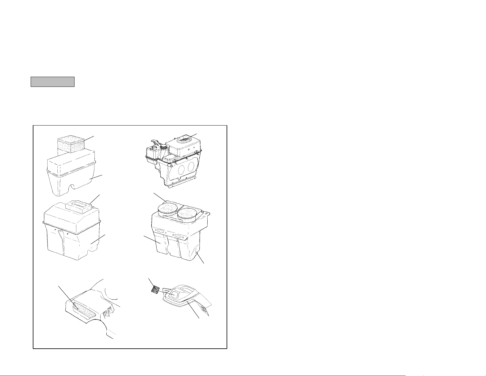
MAINTENANCE
Intake Filter
The intake foam filterlimits snow ingestion into the intake system. When operating
in loose powder snow, check top of foam filter periodically to remove any accumulation of snow.
Do not operate machine with the intake filters removed. This
CAUTION:
Refer to the next page for the location of the following components. NOTE: These
are general representations, y our model may differ.
1. Intake Foam Filter 2. Air Intake box 3. Air Plenum
4. Dash Cowl
can cause carburetor icing resulting in poor fuel economy or
carburetor malfunction.
1
2
1
2
1
1
2
1
1
3
54
4
Page 60

Under Hood Air Intake System
The Indy 340s are equipped
with an under hood air intake
system which should normally
be left open. The door should
be closed and latched above
35° F(2° C) for maximum perfor-
mance during warm weather
operation. Simply pull the strap
out and up to latch the door and
reverse the procedure to open
it.
MAINTENANCE
55
Page 61

MAINTENANCE
Spark Plug Selection
Original equipment parts or their equivalent should always be used. However, the
heat range of spark plugs is of utmost importance. A spark plug with a heat range
which is too high will cause engine damage. A spark plug with a heat range which
is too low will cause excessive fouling and malfunction.
In selecting a spark plug heat range for production, a manufacturer is forced to assume that the engine is going to operated under extreme heavy duty conditions.
This protectsthe engine frominternal damage in the event that the purchaseractually does operate the engine in this manner. This selection however, could cause
the customer who normallyoperatestheengine under medium or lightduty to have
spark plug failure. Refer to your Owner’s Manual Supplement for the specific spark
plug to be used in your machine.
CAUTION:
A plug with a heat range which is too high will always cause engine damage if the
engine is operated in conditions more severe thanthatforwhich the spark plug was
intended.
A new engine can cause temporary spark plug fouling even though the heat range
is proper, due to the preservative which has been added during assembly of the
engine to combat rust and corrosion. Avoid prolonged idle speeds, as plug fouling
and carbonization will result.
D Use recommended spark plugs
D Proper electrode gap is .028″/0.7mm
D Spark plug torque is 18-22 ft. lbs. (2.5-3 kg/m)
D Always carry spare spark plugs in case of an emergency
NOTE: Incorrect fuel mixture can often cause a spark plug to appear to be too dark
or too light in color. Before changing spark plug heat ranges, be sure the correct
main jet is installed in the carburetor(s).
The spark plug and its condition is indicative of engine operation. The spark plug
firing end condition should be read after the engine is warmed up and the vehicle
is driven at higher speeds. Immediately check the spark plug for correct color.
Normal
The insulator tip is gray, tan, or light brown. There will be a few combustion deposits. The electrodes are not burned or eroded. This indicates the proper type and
heat range for the engine and the service.
NOTE: The tip should not be white. A white insulator tip indicates overheating,
caused by use of an improper spark plug or incorrect carburetion adjustments.
Wet Fouled
The insulator tip is black. A damp oily film covers the firing end. There may be a
carbon layer over the entire nose. Generally, the electrodes are not worn. General
causes are excessive oil, use of non-recommended injection oil, excessive idling,
idle too low or too rich, or weak ignition output.
56
Page 62
Spark Plug Removal and Replacement
WARNING
Never attempt to remove the spark plug while
the engine is warm. The exhaust system or engine could burn you, causing severe injury.
The spark plug is removed by using the special
wrench (1) provided in the tool kit. Remove the
spark plug c ap. Remove the spark plug by rotating counterclockwise.
Reverse the procedure for spark plug installation. Torque to 18-22 ft. lbs. (2.5-3 kg/m).
NOTE: Always check the gap on new spark
plugs with a wire gauge.
MAINTENANCE
1
57
Page 63

MAINTENANCE
Water Pump Belt Inspection
Some liquid cooled models will
require an inspection of the waterpump belt. This belt inspection interval is 1500 miles (2400
km). Inspect belt width and condition as illustrated and replace
if cracking or worn past the
width service limit (.250″ /
6.35mm). If the belt needs to be
replaced, see your Polaris dealer.
Replace if width is less
than .25″ (6.35mm).
Nominal new width is
.345″ (8.75mm).
58
Page 64

MAINTENANCE
Water/Sediment Trap Service
Most Polaris snowmobiles incorporate patented carburetor bowl water/sediment
traps which are located at the bottom of each carburetor. The trap consists of a
hose with a plug, which should be inspected for contamination and drained at least
every 2000 miles (3200 km).
WARNING
When draining the traps, fuel spillage will occur. Be sure to work in a well ventilated
area away from anything which may cause the fuel to ignite such as open flames,
sparks, heaters, trouble lights, cigarettes, etc.
Cleaning Procedure - Plug
1. Turn the fuel tank supply valve off.
2. Position a container or shop towels
to catch the contaminated
gasoline.
Heed the gasoline warnings
found on page 34.
3. Slide the clamp (1) away from the
drain plug (2) and remove the drain
plug from the sediment tube.
4. Wipe off residue from plug and
reinstall with clamps. Continue
until all the traps have been
emptied.
Cleaning Procedure - Nipple
1. Turn the fuel tank supply valve off.
2. Position a container or shop towels
to catch the contaminated
gasoline.
3. Slide the clamp (1) away from the
nipple (3) and remove the nipple.
Empty the tube and reinstall.
Continue until all the traps have
been emptied.
2
1
1
3
59
Page 65

MAINTENANCE
Fuel Filter/Fuel Lines
CAUTION:
The fuel filter (3 - external fuel filter) (4 - in-tank
fuel filter) and fuel lines should be inspected
regularly. Special attention should be given to
the system’s fuel line condition after periods of
storage. Normal deterioration from weather
and fuel compounds can occur.
Oil Filter
The oil filter (5) is of a special design and must
not be substituted. This filter should be
changed annually or every 1200 miles (1920
km). Inspect oil line condition at 2000 miles
(3200 km).
NOTE: The direction of the arrows indicates
the direction of the flow through the filters.
NOTE: After changing the oil filter, the oil injection system must be bled of all trapped air. See
your dealer for instructions or have your dealer
perform the filter change and bleeding operation for you.
The only oil recommended for this system is
Polaris brand oil.
3
4
5
60
Page 66

MAINTENANCE
General Carburetor Information
The number size stamped in the end of the main jet indicatesthe jet size which was
installed at the time of manufacture.
The installed main jet is not necessarily correct for your elevation.
It is the Polaris dealer’s responsibility to ensure that the correct main jets are
installed in each machine for your area of operation.
WARNING
Carburetor adjustments should be performed only by a knowledgeable service
technician at a Polaris servicing dealer using the proper tools, procedures and
specifications.
Carburetor Adjustments
Proper carburetor adjustments include the following:
D Carburetor component changes for specific altitude and ambient temperatures;
D Choke adjustment and synchronization;
D Air screw settings, if applicable;
D Idle RPM adjustments;
D Equalizing air flow at idle;
D Equalizing air flow at off idle;
D Throttle safety switch checks and servicing;
D Throttle block to throttle flipper clearance adjustment; and
D Oil pump lever and cable adjustment, where applicable.
The frequency at which the carburetorsare synchronized or balanced is important.
Properlyadjustedcarburetors can greatly improve engine performance, fuel economy, engine life and reliability.
Improperly adjusted or unsynchronized carburetors can lead to one or more of the
following:
D Hard starting.
D Poor idle.
D Overheated pistons and cylinder walls.
D Plug fouling.
D Poor engine response to various throttle valve openings.
61
Page 67

MAINTENANCE
ACCS
1
3
2
1. Air Box
2. Vent Line Attachment
3. ACCS Valve
Some models are equipped with the Polaris ACCS (Altitude Compensating Carburetor System). The ACCS is designed to compensate automatically for changes
in altitude without having to change carburetor jets. See your dealer for ACCS service or adjustment.
2
62
Page 68

MAINTENANCE
Carburetor Protection During Off Season Storage
Whenever the machine is stored for a period of more than 60 days it is highly recommended that the engine be fogged with Polaris PN 2870791. Follow the engine
fogging instructions provided on the can. See pages 85-86 for more complete information about storing your machine during the off s eason.
When preparing your snowmobile for off season storage we recommend that you
add a fuel conditioner/stabilizer or Premium Carbon Clean (2871326) to the fuel
tank. Follow the instructions on the can. Run the engine for five minutes to get additives through the entire fuel system. Then top off with fresh fuel.
If stabilizer is not used, the carburetors should be drained by removing the water
trap drain plugs. Catch fuel in a container or shop cloth. Reinstall plugs securely.
Observe all fire safety rules when draining carburetors. See gasoline warnings on
page 34.
CAUTION:
Using lower than the recommended octane fuels or operating with obstructed fuel
systems will lead to costly engine damage.
Exhaust System
At approximately 2000 miles (3200 km) it is a good idea to check the exhaust system forwear or damage. To inspect,allowengineand exhaust system to cool completely. Open the hood and inspect the muffler and pipes for cracks or damage.
Check for weak or missing retaining springs or damper/support grommets.
WARNING
Exhaust system temperatures can exceed 900° F (500° C). Serious burns may
occur if this inspection is performedwithoutallowing adequate time for the exhaust
system to cool. Never perform this procedure with the engine running.
63
Page 69

MAINTENANCE
Engine Cooling - Liquid Cooled Models
The cooling system on the liquid cooled Indy consists of the following major components: recovery tank, water pump, cylinders, heads, inlet and outlet manifolds,
pressurecap and heat exchangers. The heat exchangers are located beneath the
running boards and front close-off panel in front of the drive shaft and/or under the
seat. Coolant is pumped through the cylinders,heads,and manifolds. The coolant
is then pumped through the heat exchangers, where it is cooled as snow comes
in contact with the fins on each exchanger. The “cooled down” fluid then returns
to the water pump and is re-circulated.
Coolant Mixture
The coolant supplied in the system is a 50-50 mixture of ethylene-glycol and distilled water. This mixture will provide protection against freezing at temperatures
down to -34° F (-37° C). If greater protection against freezing is required, the percentage of antifreeze to water may be increased. Use Premium 60/40 anti-freeze
coolant. Never exceed a 60% antifreeze, 40% water mixture. Contact you dealer
if greater protection is required.
NOTE: Never add tap water to the cooling system. Minerals cause deposits and
may react adversely with the metals in the engine and cooling system.
Coolant High Temperature Indicator Light
The high temperature indicator light is controlled by a switch installed into the engine coolant system. If the engine coolant reaches a certain temperature, depending on the model, the switch completes a circuit which turns the light on.
If you must drive the machine back to your starting point, drive slowly and stop frequently to allow normal cool down of the engine. Contact your dealer.
Coolant Level
The engine coolant level is controlled or maintained by the recovery system. The
recovery system components are: the coolant tank or overflow tank, engine filler
neck, pressure cap (in some models), and connecting hoses.
As coolant operating temperature increases, the expanding excess coolant is
forced out of the engine, past the pressure cap (if applicable), and into the overflow
tank. As engine coolant temperature decreases, this contracting coolant is drawn
back up from the tank, past the pressure cap or filter and check valve, and back
into the engine.
CAUTION:
The coolant reservoir or surge tank must be maintained between the minimum and
maximum levels to prevent overheating and serious engine damage. Some models, maintain coolant level at the “full cold” line on the coolant tank with the engine
cold.
Flushing the Cooling System
To ensure that the coolant maintains its ability to protect the engine, the system
should be completely drained every two years and a fresh 50/50 or 60/40 mixture
of antifreeze and distilled water should be added. This service must be done when
the engine is cold.
64
Page 70

MAINTENANCE
Bleeding the Cooling System
WARNING
Never bleed the cooling system when the engine
is hot. Severe personal injury could result from
steam or hot liquid.
Never remove the pressure cap (1) when the engine is warm or hot. If the pressure cap is to be removed, the engine must be cool.
Use of a non-standard pressure cap will not allow
the recovery system to function properly. If the cap
should need replacement contact your dealer for
the correct replacement part and pressure rating.
Recovery System Models
If the coolant level becomes low in the recovery
tank, the system should be bled of any trapped air
using the following procedure:
1. Fill the recovery tank with coolant to the
maximum indicated mark.
2. Elevate front end of machine slightly to aid
bleeding of the heat exchangers.
3. With pressure cap removed, add coolant and
fill to the top of the filler neck.
4. Install the pressure cap with the lever lock up
in its release position.
5. Run the engine at slow (600 RPM) for two to three minutes. This will purge the
system of trapped air.
6. Close the lever lock and check recovery tank fluid level.
1
2
CAUTION:
Most cooling systems are equipped with a filter (2) which should be periodically inspected or replaced. If coolant flow becomes restricted or plugged, coolant loss,
air lock or engine damage may result.
65
Page 71

MAINTENANCE
SurgeTankModels
1. Remove the pressure cap from the recovery tank and fill with properly mixed
coolant to the maximum indicated mark.
2. Elevate front end of machine slightly to aid bleeding of the heat exchangers.
3. Remove the bleed screw from the water outlet manifold and/or the thermostat
housing. Allow the coolant to bleed through the system until it runs out the
bleed holes. Reinstall the bleed screw into the manifold.
4. Fill the recovery tank back to the maximum indicated mark.
5. Start the engine and run at a fast idle for two to three minutes. Occasionally
loosen the bleed screw to purge any trapped air in the system.
6. Shut off engine and check the recovery tank level. Fill as required.
7. Feel the heat exchangers under the running boards. If the system is bled
properly, they will be warm to the touch. If they are not, repeat step four and lift
the front of the machine slightly to assist in the bleeding.
Throttle Cable Lubrication
With the engine off, lubricate the
throttle cable occasionally with Polaris Cable Lubricant (PN 2870510).
Turn the handlebars to the left and lubricate liberally as shown.
Choke and Cable Lubrication
Lubricate the choke slide and cables
occasionally as shown with Polaris
Cable Lubricant(PN2870510). Operate the choke intermittently before
turning the machine off. This draws
moisture out of the choke plunger
area and reduces the possibility of the
choke becoming frozen.
66
Page 72

MAINTENANCE
Chaincase Oil Level
The drive chain is continuously immersed in oil. Proper oil level is determined by
checking the level on the dipstick (C) with machine placed on a level surface. The
oil level should be between the “safe” marks on the dipstick. Add oil through dipstick opening to maintain proper level. Use Polaris chaincase oil (PN 2871280).
Do not overfill.
NOTE: Clean the magnetic plug (D) every 500 miles (800 km) and whenever
checking or changing lubricant.
CAUTION:
Do not mix or use other types of lubricant. Excessive wear to chain, sprockets and
bearings will result.
It is the owner’s responsibility to maintain proper lubrication of the chaincase.
Drive Chain Tension
To obtain correct chain tension:
1. Rotate driven clutch
counterclockwise to move all
chain slack to the tensioner
side. Lock the brake lever lock
or have an assistant hold the
brake lever firmly.
2. Loosen the adjuster bolt jam
nut (A).
3. Finger tighten the adjuster bolt
(B) until it can no longer be
adjusted by hand.
4. Back off the adjuster bolt by 1/4
turn.
5. Tighten the jam nut while
holding the adjuster bolt.
6. The chain is now tensioned.
Release the brake lever lock.
D
C
B
A
67
Page 73

MAINTENANCE
Gearcase Oil Level (WideTrak Models)
Using Polaris Chaincase Oil (PN
2871281), maintain the proper oil level. Proper oil level is determined by
checking the level on the dipstick (A)
with machine placed on a level surface. The oil level should be between
the “safe” marks on the dipstick. Add
oil through dipstick opening to maintain proper level. Do not overfill.
NOTE: Clean the magnetic plug (B)
every 500 miles (800 km) and whenever checking or changing lubricant.
CAUTION:
Do not mix or use other types of lubricant. Excessive wear to chain,
sprockets and bearings will result.
It is the owner’s responsibility to maintain properlubrication of the gearcase.
A
B
68
Page 74
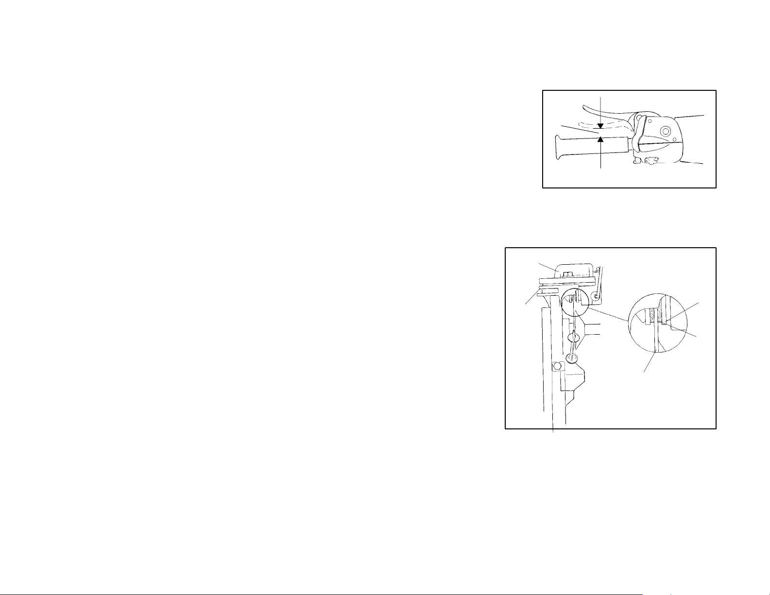
Brake Inspection
The brake lever reserve should
be inspected frequently. Measure the clearance between the
lever and handlebar grip. Inspection should be made with
the lever firmly depressed. Lever reserve (A) should be no
less than 1/2″ (1.3 cm).
Replacement of brake pads will
be necessary when the brake
pad material is thinner than the
backing plate approximately
(1/16″). A kit is available for replacing brake pads. See your
dealer.
1. Brake Caliper
2. Chaincase
3. Brake Disc
4. Backing Plate
5. Brake Pad Materi-
al (Replace when
thickness is less than
1/16″.
2
MAINTENANCE
A
1
4
5
3
Excessive Lever Travel
The snowmobile’s hydraulic brakes are self-adjusting. If excessive brake pad
clearance should develop, the machine should be returned to an authorized Polaris dealer for inspection and adjustment.
69
Page 75

MAINTENANCE
Replenishing Brake Fluid
CAUTION:
Brake fluid is a hazardous material. Contact with decals, paint, and many plastics
will cause damage. Use proper precautions when handling brake fluid.
Remove brake fluid master cylinder reservoir cover. Add Polaris brake fluid (PN
2870990) as required to bring the level up to the top of the fluid level mark on the
inside of the reservoir. The proper fluid level is 1/4-5/16″ (.6-.8 cm) below the lip
of the reservoir opening on most models.
NOTE: On some models, the brake fluid level can be seen through a plastic sight
glass in the brake reservoir. If the fluid is sufficient, the sightglass will be black. If
the sight glass is any color other than black, you will need to add brake fluid.
On all models, frequently check the reservoir to be sure it contains the correct
amount of fluid.
Use only Polaris DOT 3 high temperature brake fluid (PN 2870990). Polaris brake
fluidissoldin12oz.bottles.
WARNING
Do not over fill the master cylinder. Fluid expansion could cause brakes to lock,
resulting in serious injury or death. Once a bottle of brake fluid is opened, use what
is necessary and discard the rest. Do not store or use a partial bottle of brake fluid.
Brake fluid is hygroscopic, meaning it rapidly absorbs moisture from the air. This
causes the boiling temperature of the brake fluid to drop, leading to early brake
fade and the possibility of serious injury.
Dirt and debris should be kept off the master cylinder cover. The cover has vent
slits to allow for diaphragm movement. If these vents become plugged, movement
of brake fluid below the diaphragm may be restricted, altering brake function.
70
Page 76

MAINTENANCE
Bleeding the Hydraulic Brake System
Air in the hydraulic brake system will cause a springy or spongy brake lever action.
Bleeding is necessary to remove air from the system. Refer to illustration on page
69.
1. Remove brake fluid master cylinder reservoir cover and gasket.
CAUTION:
Brake fluid is a hazardous material. Contact with decals, paint, and many plastics
will cause damage. Use proper precautions when handling brake fluid.
2. Fill the master cylinder reservoir (B) and replace gasket and cover. Keep the
fluid level 1/4-5/16″ (.6-.8 cm) below lip of reservoir opening.
3. Fill the master cylinder reservoir (B) and replace gasket and cover. Keep the
fluid level between the max and min marks on the side of the reservoir.
WARNING
Do not over fill the master cylinder. Fluid expansion could cause brakes to lock,
resulting in serious injury or death.
4. Slip a rubber tube over the ball of the bleeder valve and direct the flow of fluid
into an approved container.
WARNING
Never re-use brake fluid. Brake fluid is hygroscopic, meaning it rapidly absorbs
moisture from the air. This causes the boiling temperature of the brake fluid to drop,
leading to early brake fade and the possibility of serious injury.
5. Squeeze brake lever a full stroke. Then unscrew bleeder valve 3/4 of a turnto
release air.
6. Close bleeder valve and release brake lever.
Repeat steps 4 and 5 until fluid flows from bleeder valve in a solid stream free of
air bubbles.
7. Re-fill reservoir to proper level after bleeding operation. See Replenishing
Brake Fluid on page 70. Do not overfill the master cylinder.
8. Replace gasket and cover.
During the bleeding procedure make sure to keep the brake handle in as level a
position as possible. The hydraulic fluid reservoir must be in this position to minimize the possibility of air entering the system through the reservoir vent.
WARNING
Excessive or repetitive use of brakes for high speed stops will cause an overheated brake system. This overheated condition could cause sudden loss of
brakes and/or fire, resulting in severe injury or death.
When traveling in long downhill stretches remember to use a pumping brake action. Riding the brakes can cause the brake system to overheat, resulting in brake
failure.
71
Page 77
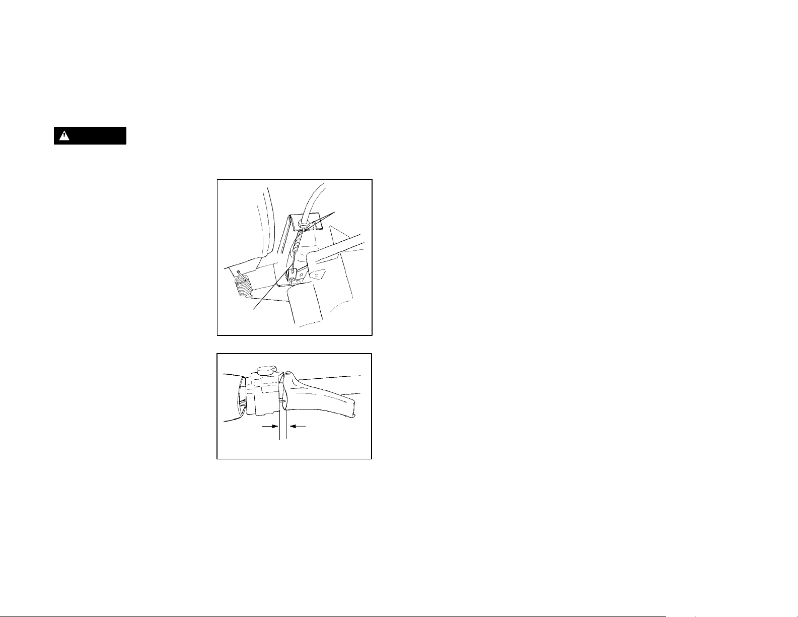
MAINTENANCE
Brake Adjustment - Mechanical Brakes
Ifexcessive brake lever to brake block clearance is evident, the brake cable or caliper should be adjusted using the following methods. When adjusting calipers,adjust caliper adjuster bolt only. Do not adjust cable or cable sleeve length.
WARNING
Improperbrakeadjustment could resultin brake failure which could resultin severe
injury or death.
Cable Adjustment
1. Make sure floating parts move
freely and all parts are mounted
securely. Tighten hardware as
required.
2. Check actuator linkage to ensure
there is adequate freedom of
movement for positive brake
operation.
3. Loosen lock nuts (A).
4. To increase brake lever free play,
turn nuts counterclockwise to
move cable (B) down in bracket.
To decrease lever free play move
cable up in bracket. Tighten lock
nuts.
5. If cable adjuster has reached
maximum, the lever arm can be
re-indexed twice before
brakepads require replacement.
When pads are replaced, brake
lever arm must be re-indexed to
obtain proper freeplay. Brake
lever free play should be 1/4 - 3/8″
(6-10 mm).
6. Loosen lock nuts and turn counterclockwise (as viewed from the top) to obtain
the maximum amount of cable freeplay. Straighten tab on tab washer and
loosen bolt enough to disengage actuator lever spline.
B
1/4-3/8″ (6-10 mm)
A
72
Page 78
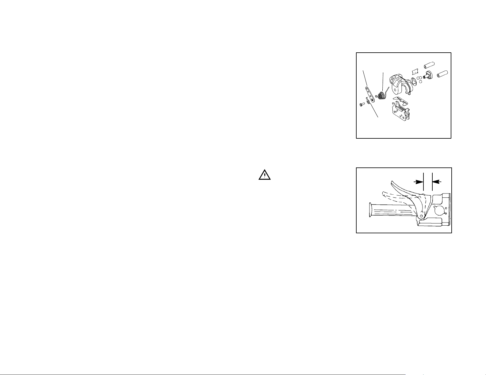
MAINTENANCE
Cable Adjustment (Cont.)
7. Slip long leg of lever spring (D) off
caliper and rotate to the side.
8. Rotate lever (E) one tooth in the
direction opposite the actuation
direction and tighten bolt. Make
sure spline teeth are properly
engaged.
9. Bend up a tab (C) aligning with one
of the bolt head flats to prevent bolt
rotation.
10. Return the spring to its original
position on the caliper. Both lever
and linkage must be free to return
to original position.
11. Perform steps 3. and 4. to adjust lever freeplay.
12. Verify proper brake operation. Disc should rotate freely without drag.
13. Check disc surface condition.
E
D
C
Mechanical Brakes
Brake Lever Travel
Measure the clearance between the
lever and brake block. Inspection
should be made with the lever firmly
depressed. Distance B should be no
more than 3/4″ (1.9 cm).
Excessive travel indicates a need to
adjust the brake cable adjuster. Refer to the mechanical brake adjustment information on page 72.
B
73
Page 79
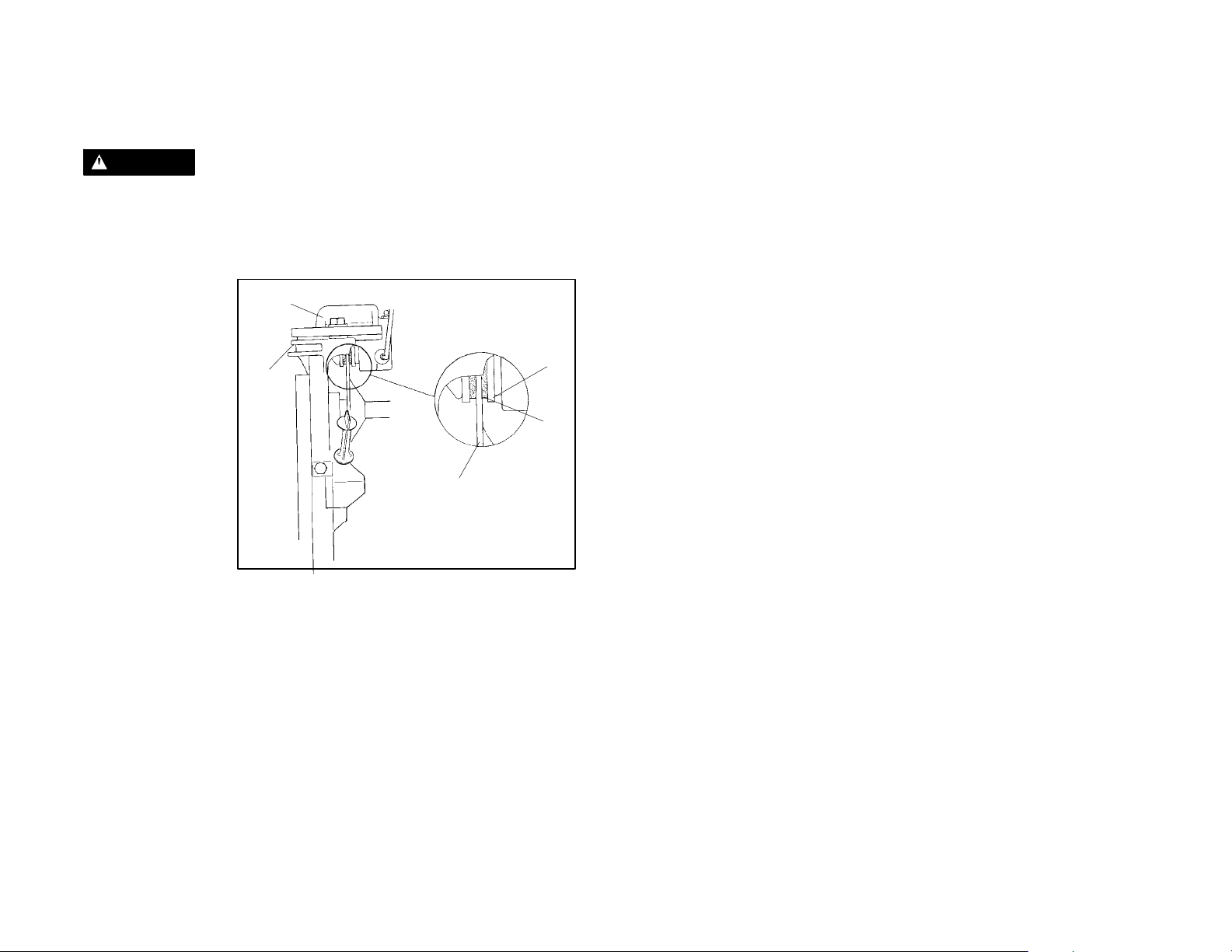
MAINTENANCE
Brake Inspection
WARNING
Be certain brake pads do not drag on disc and brake lever travel is not excessive.
Replacement of brake pads will be necessary when the brake pad material is thin-
ner than the backing plate approximately (1/16″). A kit is available for replacing
brake pads. See your dealer.
1. Brake Caliper
2. Chaincase
3. Brake Disc
4. Backing Plate
5. Brake Pad Material (Replace when
thickness is less
than 1/16″.
1
2
3
4
5
74
Page 80

Headlight Adjustment
The headlight can be adjusted for vertical
aim using the following procedure:
1. Place snowmobile on a level surface
with headlight approximately 25’
(7.6m) from a wall.
2. Measure distance from floor to
center of headlight and make a mark
on the wall.
3. Start engine and turn headlight
switch to high beam.
4. Observe headlight aim. The most
intense part of the headlight beam
should be aimed 2″ (5.1 cm) below
the mark placed on the wall in Step 2.
NOTE: Rider weight must be
included on the seat.
5. On evolved models, turn the
adjustment knob (B) located inside
the hood just below the headlamp
opening. Turn knob in or out as
needed for proper aim. On
aggressive models, insert a Phillips
screwdriver into the access hole (C)
on the top of the instrument housing
and turning the screw until correct
adjustment is achieved.
MAINTENANCE
25’ (7.6 m)
Lamp Center
Height
2″ (5.1 cm)
B
OR
C
75
Page 81

MAINTENANCE
NOTE: Do not touch a halogen bulb with bare fingers. Oil from skin leaves a resi-
due, causing a hot spot which will shorten the life of the lamp.
Removing Halogen Bulbs - Low Beam
1. Pinch ends of the spring (1) together
and liftuntilit releases from the spring
retainer.
2. Lift spring carefully around wire
harness (2) and flip to outside of
housing.
3. With the wire harness attached to the
bulb (3), withdraw bulb from housing.
4. Grasp bulb by metal base and
carefully separate bulb from
harness.
Installing the Bulb
1. Hold bulb by metal base and install into wire harness.
2. Insert bulb into housing.
3. Carefully flip spring back into housing placing it around wire harness.
4. Squeeze spring together until it is over the spring retainer and release.
5. Verify headlight aim.
2
3
1
Removing Halogen Bulbs - High Beam
1. Remove the wire harness
2. Gasp the bulb firmly and twist it 1/2
turn counterclockwise.
NOTE: Do not touch a halogen bulb with
bare fingers. Oil from skin leaves a residue, causing a hot spot which will shorten
thelifeofthelamp.
3. Remove the bulb from housing and
replace with new bulb.
4. Place the bulb and housing back
inside the hole and turn the housing
1/2turnclockwisetolockintoplace.
5. Reinstall the wire harness to the
housing.
76
Page 82

MAINTENANCE
NOTE: Do not touch a halogen bulb with bare fingers. Oil from skin leaves a resi-
due, causing a hot spot which will shorten the life of the lamp.
Removing the Side Bulbs
1. Disconnect terminal from back of bulb.
2. Turn bulb assembly 1/4 turn to right and withdraw from housing.
Installing the Side Bulbs
1. Hold bulb assembly by plastic base and plug into wire terminal.
2. Insert bulb assembly into housing.
3. Turn bulb assembly 1/4 turn to left to secure in housing.
4. Verify headlight operation.
Wrap Around Taillight Bulb Replacement
1. Remove Phillips screws from
taillight lens (A).
A
2. Working from front to back,
carefully pry lens away from seal
and remove lens.
3. Pull bulb(s) (B) straight out from
socket and insert new bulb.
4. Reinstall lens.
B
77
Page 83

MAINTENANCE
Handlebar Adjustment - All Other Models
Your snowmobile has handlebars
which may be adjusted for your personal fit.
2
1. Remove handlebar cover and
foam.
1
2. Usinga7/16″ (11 mm) wrench,
loosen four nuts on bottom of
adjuster block. NOTE: Turn
handlebar to left or right for access
to back nuts.
3. Adjust handlebar to the desired height. Be sure that handlebars, brake lever
and throttle lever operate smoothly and do not hit the gas tank, windshield or
any other part of the machine when turned fully to the left or right.
4. Torque the handlebar adjuster block bolts to 11-13 ft. lbs. (1.5-1.8 kg/m).
5. Replace handlebar cover and foam.
3
4
78
Page 84

MAINTENANCE
Backrest Adjustment
The passenger backrest on s ome models is adjustable. To move the backrest forward or backward, lift the adjustment lever on the left side (A).
To lengthen or shorten the backrest cable, lift the cable until spring tension is felt
and lock the jamb nut.
When adjusting the backrest from a passenger position to a single rider position,
rotatethebackrestcushionadjustmentknobs (B) until the proper angle is reached.
The grab bars have five height adjustments. To raise or lower the grab bar, remove
the grab bar adjuster knob (C), positionthe grab bar at the desired height, and reinstall the knob.
Some models are also equipped with passenger handwarmers. The switch (D),
located under the left hand wind deflector, has three settings: High, Off, and Low.
B
D
A
C
79
Page 85

MAINTENANCE
Drive Belt
WARNING
Periodically check the condition and tension of the drive belt. Always carry a spare
belt. Inspect clutch sheaves for damage, wear, or belt residue. Clean with non-oil
base cleaner such as isopropyl alcohol.
To ensure satisfactory belt life, install belts so they operate in the same direction
of rotation. Position the identification numbers so that you can read them. This will
keep the belt rotating in the same direction.
For improved drive away during extreme cold temperatures, remove the belt and
warm it up to room temperature. Reinstall it before starting the vehicle.
Belt Removal - A
1. Be sure key switch is off and
engine has come to a complete
stop. Remove the retaining
knob or pin and open the clutch
guard.
2. Apply brake (or lock parking
brake if so equipped).
3. Grasp belt firmly midway
between clutches and pull
upward and rearward. Remove
the belt.
Belt Installation - B
1. Drop the drive belt over the
drive clutch and pull back the
slack. Numbers should be
readable from right side of unit.
2. Turn the driven clutch
moveable sheave clockwise
while at the same time pushing
inward and forcing the belt
down between the sheaves.
3. Hold the belt down between the
sheaves and roll the bottom
portion over the outer clutch
sheave. Once installed, be sure
to work the belt to the outer
edge of the sheave. Be sure to
release parkingbrakeifapplied.
4. Close the clutch guard and
reinstall the retaining knob or
pin.
80
A
A.3
B
B.1
B.3
Page 86

MAINTENANCE
Clutch System
Do not lubricate clutchbushings. The bushings in the weights and rollers of Polaris
clutches are made of a material which may be damaged if lubricated. Clean clutch
sheaves periodically to maintain optimum performance.
WARNING
All clutch maintenance and repairs
must be performed by an authorized
Polaris servicing dealer. Any unauthorized modifications to clutches,
such as adding or removing weights
will void the warranty.
If you become aware of higher than
normal engagement, an unusual
vibration, or an unusual shift pattern,
contact your dealer immediately. Do
not operate the machine until corrections have been made.
Clutch Alignment and Offset
The primary drive belt is a very important part of the drive train. Proper adjustment of the two clutches (torque
converter assembly) is necessary to
obtain proper belt life. The information on this page is most important in
maintaining proper tolerances. If you
desire more information, consult your
dealer.
See Owner’s
Manual Specification Supplement for
specification
Clutch Alignment
The recommended offset between the drive and driven clutches with the belt removed is found on the Owner’s Manual Specification Supplement.
Clutch center distance and alignment are crucial in maintaining optimum performance. The drive belt is a very important part of the drive system. Belt to sheave
clearance in the drive clutch should be kept at a minimum. With a new belt, the
least amount of clearance will provide the best throttle response. See your dealer
for adjustments. Belt width and length must match the c enter distance of the
clutches and sheave width of the drive clutch. For this reason, Polaris recommends that only O.E.M. belts be used. Other belts may match the dimensions, but
can drastically change the shift pattern, resulting in poor performance characteristics.
NOTE: A worn belt will continue to function, but will not deliver maximum performance. Always carry a spare belt in case of an emergency. Belt removal and
installation are covered on page 80.
81
Page 87

MAINTENANCE
Clutch Center Distance
Measure belt deflection with both
clutches at rest and in their full neutral
position.
Place a straight edge on the belt and
apply downward pressure while measuring at the point shown.
The recommended center distance
for your machine can be found on the
Owner’s Manual Specification Supplement.
Due to tolerances in belt length, it may
be necessary for your dealer to make
minoradjustments in the driven clutch
to achieve c orrect belt tension.
Measure at
this point
Belt Tension
Straight Edge
Belt Deflection Adjustment (P-85 System)
Adjustment can be done on P-85 clutches without removing the clutch from the
jackshaft.
1. Pull belt into driven clutch to slightly open sheaves.
2. Loosen the three bolts on the adjustment cam.
3. To reduce distance between sheaves, turn cam counterclockwise. Torque
bolts to 10 ft. lbs. (1.4 kg/m)
NOTE: If your model has a P-90 clutch, any adjustments must be performed by
your dealer.
82
Page 88

MAINTENANCE
Torque Stop
If your machine is equipped with a torque stop, periodically check torque stop
clearance. Before this procedure it will be necessary to ensure the clutches are
properly aligned. The torque stop clearance should be a minimum of .010″ to a
maximum of .030″ from the engine case. Adjust if necessary and lock jam nut.
Reverse Kit Maintenance
If your machine is equipped with reverse or if you have a reverse kit installed, it is
especially important to maintain track tension as specified on page 89.
WARNING
If specified track tension is not maintained severe damage to the machine may occur,which can result in loss of vehicle control. Loss of control can result in severe
personal injury or death.
D Never attempt to shift into reverse while machine is moving.
D Allow engine to reach idle speed before attempting to shift into or out of reverse.
CAUTION:
If machine has not come to a complete stop before shifting, damage will occur to
chaincase or transmission.
If you have had a reverse kit installed on your snowmobile, some maintenance will
be required. Follow these recommendations:
Chain Tension
Maintain the proper chain tension. See page 67.
Oil Level
Maintain the oil level between the safe marks on the dipstick.
Oil Change
Change the oil annually.
83
Page 89

MAINTENANCE
Reverse Operation
WARNING
This snowmobile is capable of excessive reverse speed! Reverse operation can
be dangerous even at moderate speeds. Steering control becomes difficult in reverse. Misuse of reverse can result in serious injury or death.
The transmission may not always be in the gear indicated by the shift lever. Apply
the throttle slowly until the correct gear is assured.
Make sure the shift lever is shifted completely into forward or reverse position. Do
not force the shift lever into reverse if resistance is felt.
The gears may not always be aligned for shifting into reverse. Forcing the lever
may cause the cable to bend. If resistance is felt, apply the throttle to move the
gears to a different position and try to shift again.
Sometimes the drive belt will drag in the drive clutch causing slight tension in the
transmission, making it hard to shift. Shuttingthe engineoffwill remove thistension
and ease shifting. This should only happen during the break in of a new belt or if
the drive/driven clutch center distance is too long. If this is the case, belt tension
adjustments s hould be made by your dealer.
84
Page 90

MAINTENANCE
Extended Storage
Offseason or extended storage of your snowmobile requires you to take preventative measures to aid against deterioration and to prolong the useful life of many
components.
Cleaning and Preservation of Hood, Chassis, and Trim
Proper storage starts by cleaning, washing, and waxing the hood, chassis, upholstery, and plastic parts. Clean and touch up with paint any rusted or bare metal
surfaces. Be sure that corrosive salt and acids are removed from surfaces before
beginning preservation with waxes and rust inhibitors (grease, oil or paint).
The machine should be stored in a dry garage or shed out of direct sunlight and
covered with a fabric snowmobile cover. Plastic tarp c an cause condensation to
form and damage some snowmobile components.
Controls and Linkage
All bushings, spindle shafts, and tie rod ends should be coated with a light coat of
oil or grease. Throttle controls and cables should be lubricated with Polaris cable
lubricant (PN 2870510). Force a small amount of lubricant down the cable.
Bearings
To prevent corrosion which will destroy the bearings, always grease jackshaft and
drive s haft clutch side bearings with a high quality bearing grease. See page 52.
Electrical Connections
Separate electrical connector blocks and clean corrosive build up from connectors. Lubricate or pack connector blocks with dielectric grease (PN 2871044) and
re-connect. Replace worn or frayed electricalwire and connectors. Be sure wiring
harness is properly secured away from sharp edges, steering linkage, moving
parts, and hot exhaust.
Clutch and Drive System
Remove drive belt and store in cool dry location. Lubricate sheave faces of drive
and driven clutches with a light coat of oil or Polaris Cable Lubricant (PN 2870510).
Do not lubricate clutch components except driven clutch shaft bushing as outlined
in Snow Repair Manual.
Battery
Battery must be prepared and maintained as outlined on page 45.
Front Suspension
To minimize fatigue on the front shocks and springs, it is recommended that the
front end of the machine be safely blocked off the ground, removing tension from
the shocks and springs.
85
Page 91

MAINTENANCE
Engine and Carburetor
Proper off season preparation of the engine and fuel system is vital to the prevention of rust and corrosion formation on precision engine parts during storage.
Without proper storage, jet restriction can cause lean conditions and very poor
slow speed driving quality.
D When preparing your snowmobile for off-season storage we recommend that
you add fuel conditioner/stabilizer or Premium Carbon Clean ( PN 2871326) to
the fuel tank. Follow the instructions on the can. Run the engine for five minutes
to get additives through the entire fuel system. Then top off the tank with fresh
fuel.
D Fog the engine with Polaris Fogging Oil (PN 2870791). This is available from
your Polaris dealer. Followthe recommended procedures indicated on the can.
D If stabilizer is not used the carburetors should be drained by removing the the
drain plugs or nipples. Refer to page 59 for procedure. Catch fuel in a container
or shop cloth. Reinstall and tighten drain plugs securely. Observe all fire safety
rules when draining carburetors. See gasoline warning on page 34.
Engine and Carburetor
Using a fuel stabilizer and topping off the fuel tank eliminates the need to drain the
fuel system. If you prefer to drain the fuel tank, use the following procedure:
1. Transfer unused fuel from the fuel tank to an approved fuel container using a
siphon pump. Do not re-use fuel after storage.
2. Securely supportthe frontof the snowmobile with a jack stand so the engine is
tilted rearward.
3. Remove the spark plug(s).
4. Rotate the engine slowly,watching the piston until it is at BDC - lowest position
in the cylinder. On twin cylinder models the opposite piston will be up.
5. Pour approximately two ounces of Polaris injector oil into the s park plug hole.
6. Wait one to two minutes and perform steps 4-6. on remaining cylinders.
7. Replace the spark plugs and set machine on floor
NOTE: This procedure is performedbestwhen the frontof the machine is elevated
and the engine is tilted rearward.
Track and Suspension
Under normal conditions moderate
track tension should be maintained
during summer storage. The rear of
the machine should be supported off
the ground to allow free hanging of the
track.
HINT: For easier starting after extended storage, add Polaris Premium 2 cycle lubricant to the fuel in the tank at a 40:1 ratio and run the engine for three to five minutes before storage. This will lubricate the fuel pump diaphragm to keep it flexible
and help prevent loss of prime.
86
Page 92

MAINTENANCE
Transporting the Snowmobile
Whenever the snowmobile is transportedthe following measures should be taken:
1. Turnthefuelvalveto“Off”.
2. Be certain the fuel cap and oil cap are installed correctly.
3. Always tie the snowmobile to the transporting unit securely using suitable
straps.
87
Page 93

MAINTENANCE
Fall Tune Up
To obtain maximum performance and use from your snowmobile, we encourage
you to arrange for a fall service tune-up with your Polaris dealer. He has an experienced and trained service technician who is interested in keeping your machine
in peak operating condition.
Towing
If a situation arises requiring the snowmobile to be towed by another snowmobile,
attach the tow rope to the spindles, not the ski loops.
WARNING
Always remove the drive belt from a disabled snowmobile before towing to prevent
serious damage to the engine and drive system.
Tool Kit
To help you perform emergency and routine maintenance, a tool kit is included with
your machine. Items included in the kit are:
D Tubular Socket
D Phillips Screwdriver
D Emergency Start Strap
D Tubular Socket Handle
D Wrench
D Shielded screwdriver (only with
models that have indy select or
AFX shocks)
Remember, always keep tools
with the machine.
NOTE: Other tools are also neces-
sary to perform maintenance work.
They are called out throughout this
manual.
If necessary a replacementtoolkitmay be purchased fromyourPolarisdealer. Ask
for PN 3083227.
For Your Protection
For your added protection it is a good idea to carry the following items with your
snowmobile at all times:
S Spare Drive Belt S Extra Set of Spark Plugs
S Tow Rope S Extra Oil
S Fuel Deicer S Winter Survival Kit
S Trail Map S Owner’s Manual
S First Aid Kit
88
Page 94

Track Tension Data
MAINTENANCE
Suspension
(Refer to Specifi-
cation Supple-
ment for type)
XTRA 12 121″ none 2″ behind rail
XTRA 12 133″ none 16″ ahead of rear
XTRA 10 121″
and 133″
WideTrak Type 10 lbs. (4.54 kg) 16″ ahead of rear
XTRA Lite 121″,
133″ and 136″
XL 136″ 10 lbs. (4.54 kg) 16″ ahead of rear
Weight Measurement
Location
bumper
idler shaft
10 lbs. (4.54 kg) 16″ ahead of rear
idler shaft
idler shaft
10 lbs. (4.54 kg) 16″ ahead of rear
idler shaft
idler shaft
Measurement
1/2″ (1.27 cm)
free hanging
1-1 1/8″ (2.54 -
2.86 cm)
free hanging
3/8 - 1/2″ (1 - 1.3
cm)
3/4 - 1″ (1.9 - 2.5
cm)
3/8 - 1/2″ (1 - 1.3
cm)
3/8 - 1/2″ (1 - 1.3
cm)
WARNING
When performing the checks and adjustments recommended on the following
pages, stay clear of all moving parts to avoid serious personal injury. Do not perform track measurement or adjustments with engine running.
89
Page 95

MAINTENANCE
Track Te nsi on
Track adjustment is critical for proper handling. Always maintain correct tension
and alignment.
Tension adjustments should be
made only after the track is
warmed up and limber.
1. Turn the machine off.
2. Lift the rear of the machine
and safely support it off the
ground.
3. Place the recommended
weight or downward
pressure on the track at the
specified distance (see
chart) ahead of the center of
the rear idler wheel.
NOTE: Measure at the point
where the weight is hanging.
4. Check for specified slack
between the wear surface of
the track clip and the plastic
hi-fax (C).
If the track needs adjustment:
5. Loosen rear idler shaft bolt
(D).
6. Loosen locknuts (A) (except on models with Xtra Lite suspension).
7. Tightenorloosenthetrackadjusting screws (B) as necessary to provide equal
adjustment on both sides of the track.
8. Repeat measurement on the other side of the track. NOTE: Check more
frequently when machine is new.
9. Start machine and slowly rotate the track at least five revolutions, let the track
stop rotating by itself (do not apply brakes).
10. Check track alignment (side to side) by comparing the distance from the guide
clip to Hi-fax on both sides. Readjust until centered.
11. Tighten Locknuts (A)
12. Tighten Idler Shaft Bolt (D)
weight
C
XTRA 10
Hi-fax
C
Track
WIDETRAK
weight
B
B
A D
A
D
90
Page 96

XTRA LITE
Hi-fax
MAINTENANCE
10 lb. Weight
(4.5 kg)
B
C
Track
D
XTRA 12
2″
Track
adjusting
bolt
Rail bumper
Rear
idler
shaft
bolt
Track
Hi-fax
121″ =1/2″
133″ =1-11/8″
measured 16″ahead
of rear idler center
91
Page 97

MAINTENANCE
WARNING
When performing the following checks and adjustments, stay clear of all moving
parts to avoid serious personal injury.
Track Alignment
A periodic check should be made to see that the track is centered and running
evenly on the slide rails. Misalignment will cause excessive wear to the track and
slide rail. NOTE: If excessive hi-fax wear occurs due to poor snow conditions,
additional wheel kits are available. Consult your dealer.
1. Safely support the rear of the machine with the track off the ground.
2. Starttheengineand apply a small amount of throttleuntilthetrack turns slowly
at least five complete revolutions. Stop the engine.
3. Inspect track alignment by
looking through the track
window to make sure the
rails are evenly spaced on
each side. If the track runs to
the left, loosen left locknut
and tighten the left adjusting
bolt. If the track runs to the
right, loosen right locknut
and tighten the right
adjusting bolt.
4. After adjustments are
complete, be sure to tighten
locknuts and idler shaft
bolts. Torque to 35-40 ft. lbs.
(4.8-5.5 kg/m).
5. Repeat step 2 to verify
proper alignment.
Rail
Looking through
track window,
make sure the
rails are evenly
spaced on each
side.
Hi-fax
92
Page 98

Track Warm Up
When storing your snowmobile
outside overnight, it is recommended that the track be warmed
up prior to driving the snowmobile. This reduces belt and drive
clutch wear. To warm up the
track, safely support the rear of
the snowmobile off the ground,
start the engine and abruptly en-
gage the clutch. Allow the track to
turn for a short time. Release the
throttle, apply the brakes and
shut the engine off prior to lowering it to the ground.
WARNING
Your snowmobile is propelled by
a revolving track which must be
partially exposed for proper operation. Serious injuries may be
caused by operatorcarelessness
resulting in hands, feet, or clothing becoming entangled in the
track. Be alert. Remember,being
properly seated keeps you clear
of the track.
Never hold the snowmobile up or
stand behind it while warming up
the track. A loose track or flying
debris could cause serious personal injury or death.
MAINTENANCE
93
Page 99

MAINTENANCE
Track Inspection
WARNING
Never make this maintenance
check with the engine running, as
serious personalinjury can result.
Using a hoist, safely lift and support the rearof the snowmobile off
the ground. Rotate the track by
hand to check for any possible
damage.
To inspect track rods, carefully
examine the track along the entire length of each rod, bending
the track and inspecting for
breakage. The three most common places where breakage occurs are shown in the illustration.
If any rod damage is found, the
track should be replaced.
WARNING
Broken track rods are a serious
hazard, since they can cause a
rotating track to come off the machine. Never operate or rotate a
torn or damaged track under
power. Serious personal injury or
death may occur.
Lug
21312
Track window
94
Page 100

MAINTENANCE
Track Lubrication
WARNING
Track failure, loss of vehicle control and braking ability can result from extended
use of this vehicle on surfaces providing marginal lubrication between hi-fax and
track guide clips. Examples of marginal lubrication would include lakes without
snow cover, icy trails and no-snow conditions.
The slide rail is designed to operate in conditions with adequate snow cover in order to provide sufficient lubrication. Excessive wear indicates insufficient lubrication. New hi-fax can cause faster heat build up in limited lubrication than used hifax, resulting in excessive wear. NOTE: If excessive hi-fax wear occurs due to
poor snow conditions, additional wheel kits are available. Consult your dealer.
CAUTION:
Track damage or failure caused by operation on ice or poor lubrication conditions
will void the track warranty.
Traction Products
NOTE: Tracks with deep lug design cannot be studded.
CAUTION:
Polaris does not recommend the use of traction products on WideTrak snowmobiles.
CAUTION:
If traction products are to be added to the track, wear strips must be installed in the
tunnel to avoid excessive wear. This applies to all models.
Shims should never be added to the wear strip or track damage will result due to
lack of clearance between upper carrier wheels and track.
Use of studs greater than 1″ (2.5 cm) on machines equipped with center coolers
will result in center cooler damage, or damage to tunnel.
Always inspect for track damage before using the vehicle. Use of traction products
such as studs, ice growsers, paddles, etc. will increasethe possibility of track damage and/or failure, which could cause loss of control resulting in severe injury or
death.
In the event you wish to install studs, carbides or ice growsers, contact your Polaris
dealer for advice.
Track damage or failure resulting from improper or excessive stud installation
voids any track warranty, as does installation of the Hooker™ stud system.
95
 Loading...