

Page 1
2007 SPORTSMAN 450 / 500 EFI / 500 X2 EFI
SERVICE MANUAL
FOREWORD
This service manual is designed prim arily for use by ce rtified Polaris Mas ter Service Dealer technicians in a properly
equipped shop and should be kept available for reference. All references to left and right side of the vehicle are from
the operator's perspective when seated in a normal riding position.
Some procedures outlined in this manual require a sound knowledge of mechanical theory, tool use, and shop
procedures in order to perform the work safely and correctly. Technicians should read the text and be familiar with
service procedures before starting the work. Certain pro cedur es require the use of special tools. Use only the proper
tools as specified.
Comments or suggestions about this manual may be d irected to: Service Publications Dept. @ Polaris Sales Inc. 2100
Hwy 55 Medina Minnesota 55340.
2007 Sportsman 450 / 500 EFI / 500 X2 EFI Service Manual PN 9920560
© Copyright 2006 Polaris Sales Inc. All information contained within this publication is based on the latest product information at the time of publication . Due to constant
improvements in the design and quality of production component s, some minor discrep ancies may result between t he actual vehicle and the inf ormation presented in t his
publication. Depictions and/or procedures in this publ ication are intended f or reference use only. No liability can be accepted for omission s or inaccuracies. Any r eprinting
or reuse of the depictions and/or procedures contained within, whether whole or in part, is expressly prohibited. Printed in U.S.A.
Page 2
UNDERSTANDING MANUAL SAFETY LABELS AND DIRECTIONS
Throughout this manual, important information is brought to your attention by the following symbols:
WARNING
SAFETY ALERT WARNING indicates a potential hazard that may result in severe injury or death to the operator, bystander or
person(s) inspecting or servicing the vehicle.
CAUTION
SAFETY ALERT CAUTION indicates a potential hazard that may result in minor personal injury or damage to the vehicle.
CAUTION
CAUTION indicates special precautions that must be taken to avoid vehicle damage or property damage.
NOTE:
NOTE provides key information by clarifying instructions.
IMPORTANT:
IMPORTANT provides key reminders during disassembly, assembly and inspection of components.
TRADEMARKS
POLARIS ACKNOWLEDGES THE FOLLOWING PRODUCTS MENTIONED IN THIS MANUAL:
Loctite, Registered Trademark of the Loctite Corporation
Nyogel, Trademark of Wm. F. Nye Co.
Fluke, Registered Trademark of John Fluke Mfg. Co.
Mity-Vac, Registered Trademark of Neward Enterprises, Inc.
Torx, Registered Trademark of Textron
Hilliard, Trademark of the Hilliard Corporation
Warn, Trademark of Warn Industries
Some Polaris factory publications can be downloaded from www.polarisindustires.com, purchased from www.purepolaris.com or
by contacting the nearest Polaris dealer.
Page 3

GENERAL
1
MAINTENENCE
ENGINE
FUEL SYSTEM
BODY / SUSPENSION
CLUTCH
2
3
4
5
6
TRANSMISSION
FINAL DRIVE
BRAKES
ELECTRICAL
INTERNATIONAL
7
8
9
10
11
Page 4

NOTES
Page 5

GENERAL INFORMATION
CHAPTER 1
GENERAL INFORMATION
MODEL NUMBER INFORMATION . . . . . . . . . . . . . . . . . . . . . . . . . . . . . . . . . . . . . . . . . . 1.2
MODEL NUMBER. . . . . . . . . . . . . . . . . . . . . . . . . . . . . . . . . . . . . . . . . . . . . . . . . . . . . . .1.2
ENGINE DESIGNATION NUMBERS. . . . . . . . . . . . . . . . . . . . . . . . . . . . . . . . . . . . . . . .1.2
VEHICLE IDENTIFICATION NUMBER (VIN). . . . . . . . . . . . . . . . . . . . . . . . . . . . . . . . . .1.2
TRANSMISSION I.D. LOCATION. . . . . . . . . . . . . . . . . . . . . . . . . . . . . . . . . . . . . . . . . . .1.2
ENGINE AND MACHINE SERIAL NUMBERS. . . . . . . . . . . . . . . . . . . . . . . . . . . . . . . . .1.2
PUBLICATIONS . . . . . . . . . . . . . . . . . . . . . . . . . . . . . . . . . . . . . . . . . . . . . . . . . . . . . . . .1.3
PAINT CODES . . . . . . . . . . . . . . . . . . . . . . . . . . . . . . . . . . . . . . . . . . . . . . . . . . . . . . . . .1.3
REPLACEMENT KEYS . . . . . . . . . . . . . . . . . . . . . . . . . . . . . . . . . . . . . . . . . . . . . . . . . .1.3
SPORTSMAN ‘DELUXE’ AND ‘STANDARD’ MODEL COMPONENT COMPARISON . .1.4
SPORTSMAN X2 ‘DELUXE’ AND ‘STANDARD’ MODEL COMPONENT COMPARISON1.5
2007 SPORTSMAN 450 . . . . . . . . . . . . . . . . . . . . . . . . . . . . . . . . . . . . . . . . . . . . . . . . . . 1.6
MODEL NUMBER: A07MH46AA, AZ . . . . . . . . . . . . . . . . . . . . . . . . . . . . . . . . . . . . . . .1.6
2007 SPORTSMAN 500 EFI . . . . . . . . . . . . . . . . . . . . . . . . . . . . . . . . . . . . . . . . . . . . . . . 1.8
MODEL NUMBER: A07MH50AX, AY, AZ / A07MN50AQ, AF / A07MH50FC. . . . . . . . .1.8
2007 SPORTSMAN X-2 500 EFI. . . . . . . . . . . . . . . . . . . . . . . . . . . . . . . . . . . . . . . . . . . 1.10
MODEL NUMBER: A07TH50AU, AZ / A07TN50AF, AQ / A07TH50EA . . . . . . . . . . . .1.10
MISC. NUMBERS/CHARTS . . . . . . . . . . . . . . . . . . . . . . . . . . . . . . . . . . . . . . . . . . . . . . 1.12
STANDARD TORQUE SPECIFICATIONS. . . . . . . . . . . . . . . . . . . . . . . . . . . . . . . . . . .1.12
SAE TAP DRILL SIZES . . . . . . . . . . . . . . . . . . . . . . . . . . . . . . . . . . . . . . . . . . . . . . . . .1.13
METRIC TAP DRILL SIZES . . . . . . . . . . . . . . . . . . . . . . . . . . . . . . . . . . . . . . . . . . . . . .1.13
DECIMAL EQUIVALENTS . . . . . . . . . . . . . . . . . . . . . . . . . . . . . . . . . . . . . . . . . . . . . . .1.13
CONVERSION TABLE. . . . . . . . . . . . . . . . . . . . . . . . . . . . . . . . . . . . . . . . . . . . . . . . . .1.14
GLOSSARY OF TERMS. . . . . . . . . . . . . . . . . . . . . . . . . . . . . . . . . . . . . . . . . . . . . . . . .1.15
1
1.1
Page 6
GENERAL INFORMATION
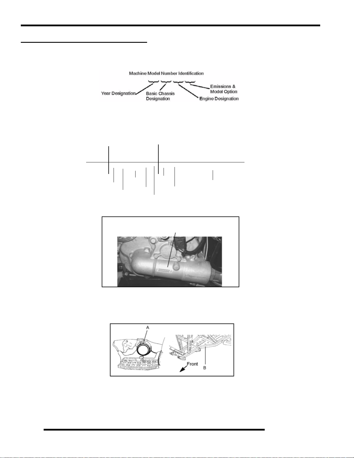
MODEL NUMBER INFORMATION
Model Number
The machine model number must be used with any correspondence regarding warranty or service.
A07 MN 50 AU
Engine Designation Numbers
EH50PLE - Single Cylinder, Liquid Cooled,4 Stroke, Electric Start
V ehicle Identification Number (VIN)
World
Mfg. ID
1 2 3 4 5 6 7 8 9 10 11 12 13 14 15 16 17
4 X A M N 5 0 A * 7 P 0 0 0 0 0 0
Vehicle Descriptor
}
Vehicle Identifier
Body Style
Transmission I.d. Location
Engine And Machine Serial Numbers
The machine model number and serial number are important for vehicle identification. Be sure to refer to the engine model number
and serial number whenever corresponding about an engine. This information can be found on the sticker applied to the top side
of the crankcase (A). An additional number is stamped on the side of the crankcase beneath the cylinder coolant elbow.
Engine
Powertrain
Emissions
The transmission I.D.number is located on top of
the transmission snorkel, right side of machine.
Model
Year
Check Digit
Plant No
Individual Serial Number
* This could be either
a number or a letter
The machine serial number is stamped on the lower left side of the frame tube (B).
1.2
Page 7
Publications
GENERAL INFORMATION
Table 1-1: Publications
Year Model Model No.
A07MN50A
2007 Sportsman 500 EFI
2007 Sportsman X2 500 EFI
2007 Sportsman 450 EFI A07MH46A 9920629 9920557 N/A
2007
Sportsman X2 500 EFI
Quadricycle
A07MH50A (Standard)
A07MH50F (Standard Intl’)
A07TN50A
A07TH50A (Standard)
A07MH46E 9920650 9920899 N/A
(Deluxe)
(Deluxe)
Owner's
Manual PN
9920364 9920365 N/A
9920632 9920902 N/A
Parts
Manual PN
Paint Codes
Table 1-2: Paint Codes
PAINTED PART
Sportsman Frame Black 9440 P-067
COLOR
DESCRIPTION
DITZLER
NUMBER
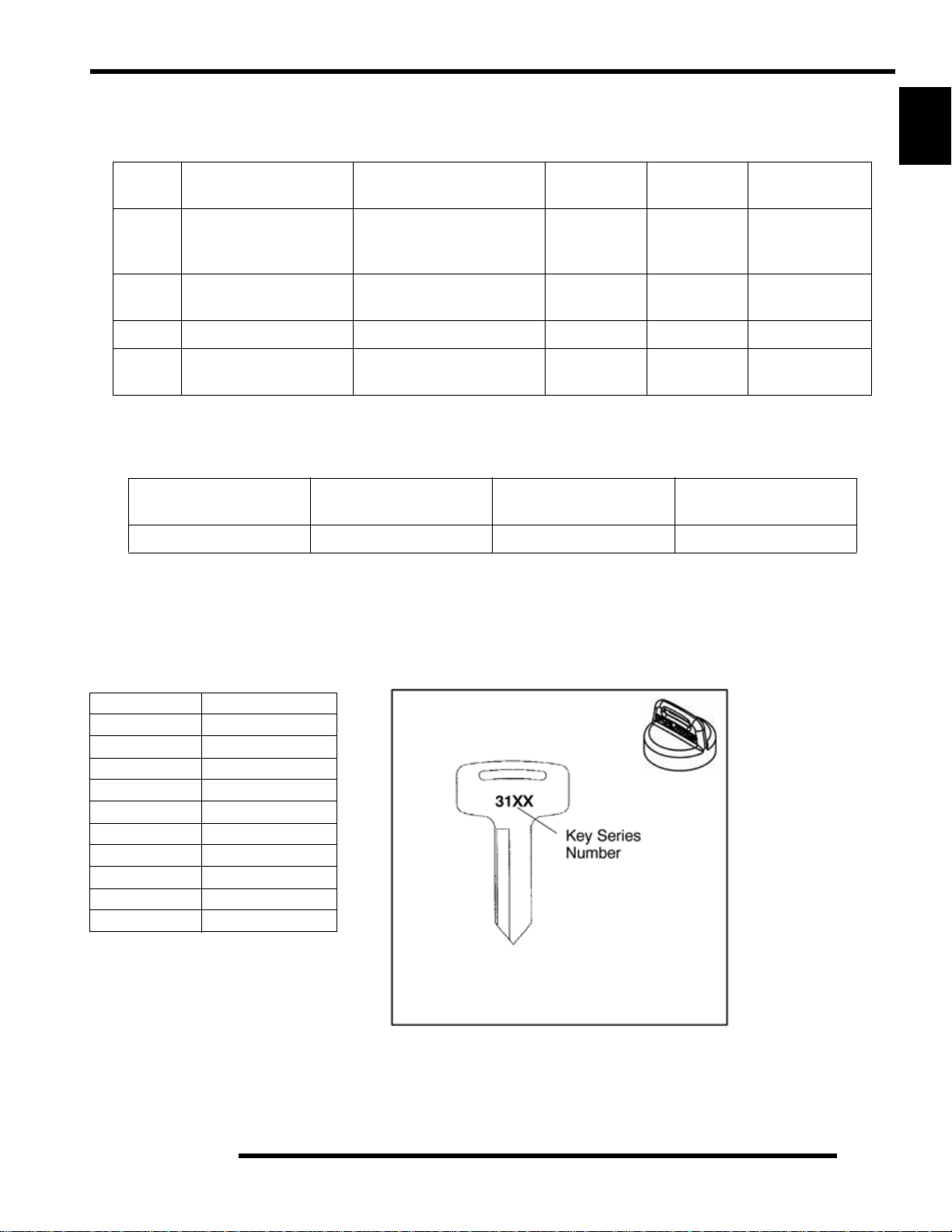
Replacement Keys
1
Parts
Micro Fiche PN
POLARIS
NUMBER
Replacement keys can be made from the original key (Phoenix excluded). To identify which series the key is, take the first two digits
on the original key and refer to the chart to the right for the proper part number. Should both keys become lost, ignition switch
replacement is required.
Table 1-3: Key Numbers
Series # Part Number
20 4010278
21 4010278
22 4010321
23 4010321
27 4010321
28 4010321
31 4110141
32 4110148
67 4010278
68 4010278
Key Cover
PN 5433534
1.3
Page 8
GENERAL INFORMATION
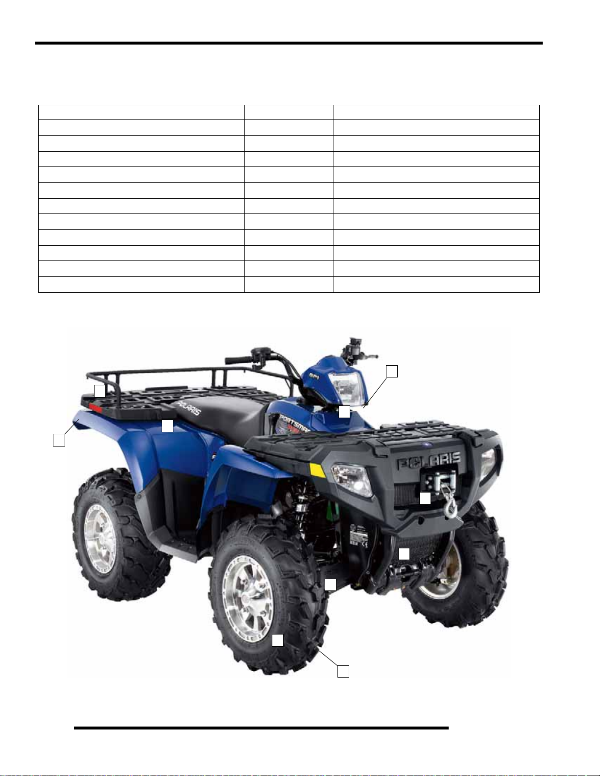
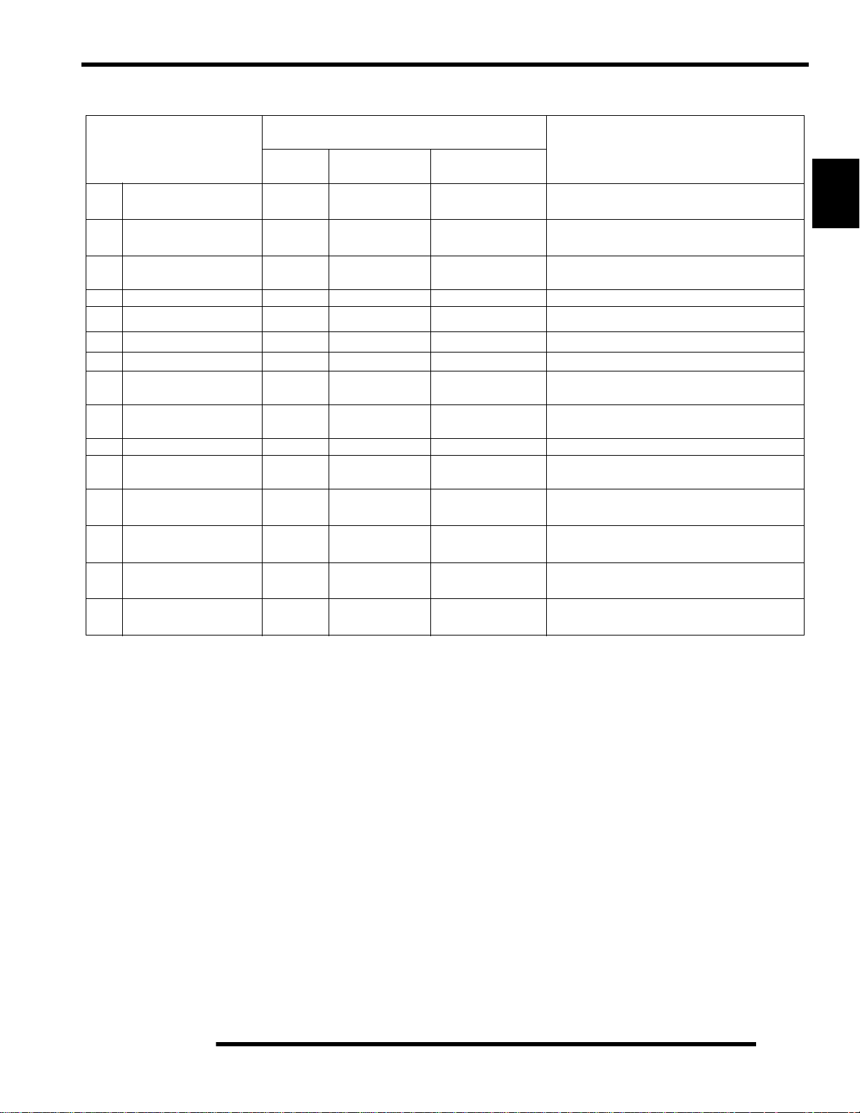
Sportsman ‘Deluxe’ and ‘Standard’ Model Component Comparison
For Model Year 2007, a Sportsman ‘Deluxe’ and ‘Standard’ model were offered. Use the following table as a guide:
SPORTSMAN ‘DELUXE’ MODEL Item Location SPORTSMAN ‘STANDARD’ MODEL
Winch 1 No Winch
PXT Tires 2 Titan Tires
PVT w/EBS 3 Non-EBS (X2 excluded)
Rear Work Lights 4 No Work Lights
Front Drive w/ Active Descent Control (ADC) 5 No Active Descent Control (ADC)
Speed Sensor Wiring for ADC 6 No Sensor Wiring Change
Rear Rack Extension 7 No Rack Extension
Cast Aluminum Wheels 8 Steel Wheels
Single Exhaust 9 Single Exhaust
Wire Harness w/ Active Descent Control (ADC) 10 Standard Wire Harness
PDM w/ Active Descent Control (ADC) 10 Standard PDM
3
7
10
9
4
1
5
6
Deluxe Model Pictured
8
1.4
2
Page 9
GENERAL INFORMATION
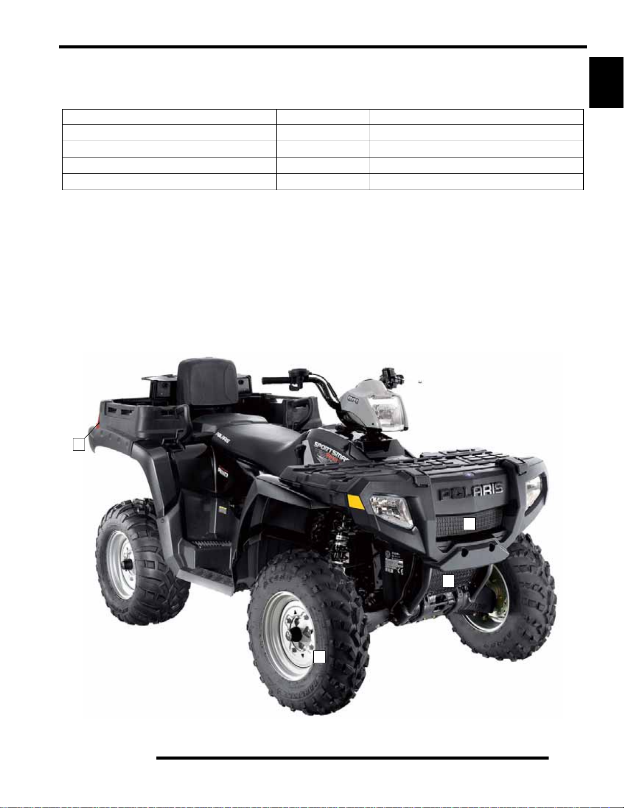
Sportsman X2 ‘Deluxe’ and ‘Standard’ Model Component Comparison
For Model Year 2007, an X2 ‘Deluxe’ and ‘Standard’ model were offered. Use the following table as a guide:
X2 ‘DELUXE’ MODEL Item Location X2 ‘STANDARD’ MODEL
Winch 1 No Winch
Rear Work Lights 2 No Work Lights
Front Drive w/ Active Descent Control (ADC) 3 No Active Descent Control (ADC)
Cast Aluminum Wheels 4 Steel Wheels
1
2
1
3
Standard Model Pictured
4
1.5
Page 10
GENERAL INFORMATION
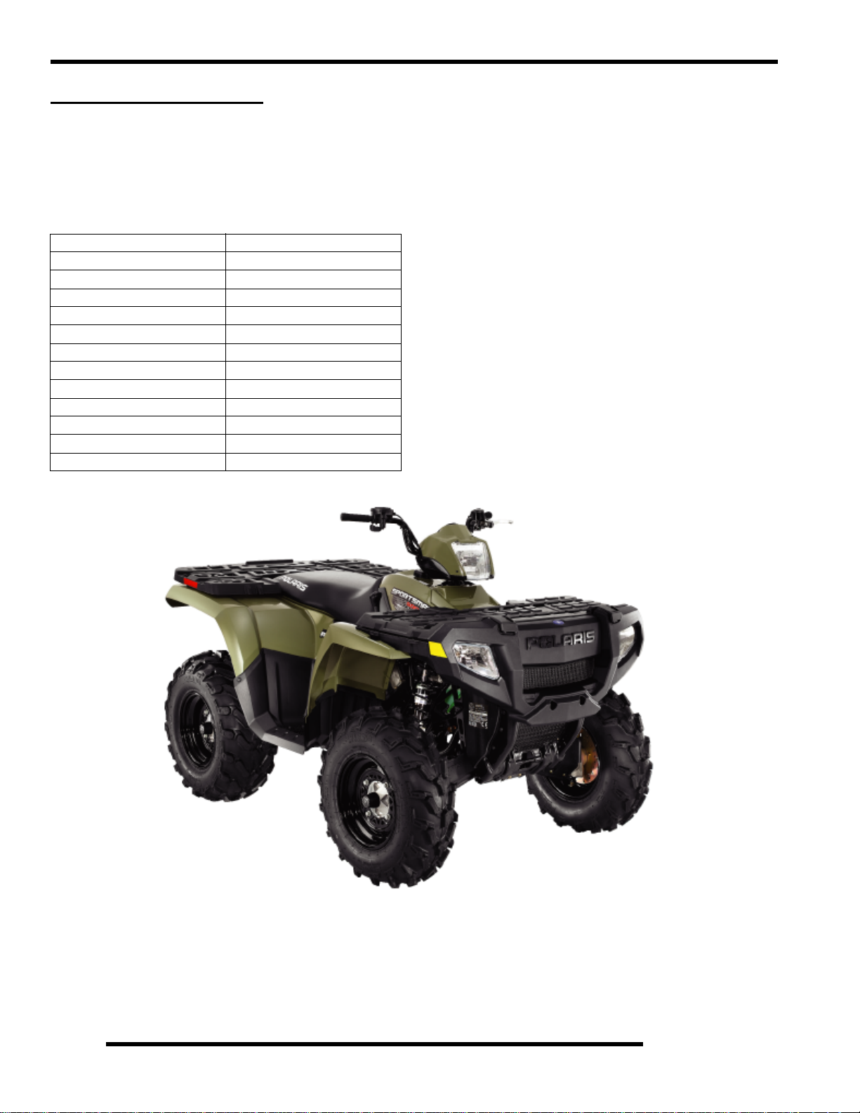
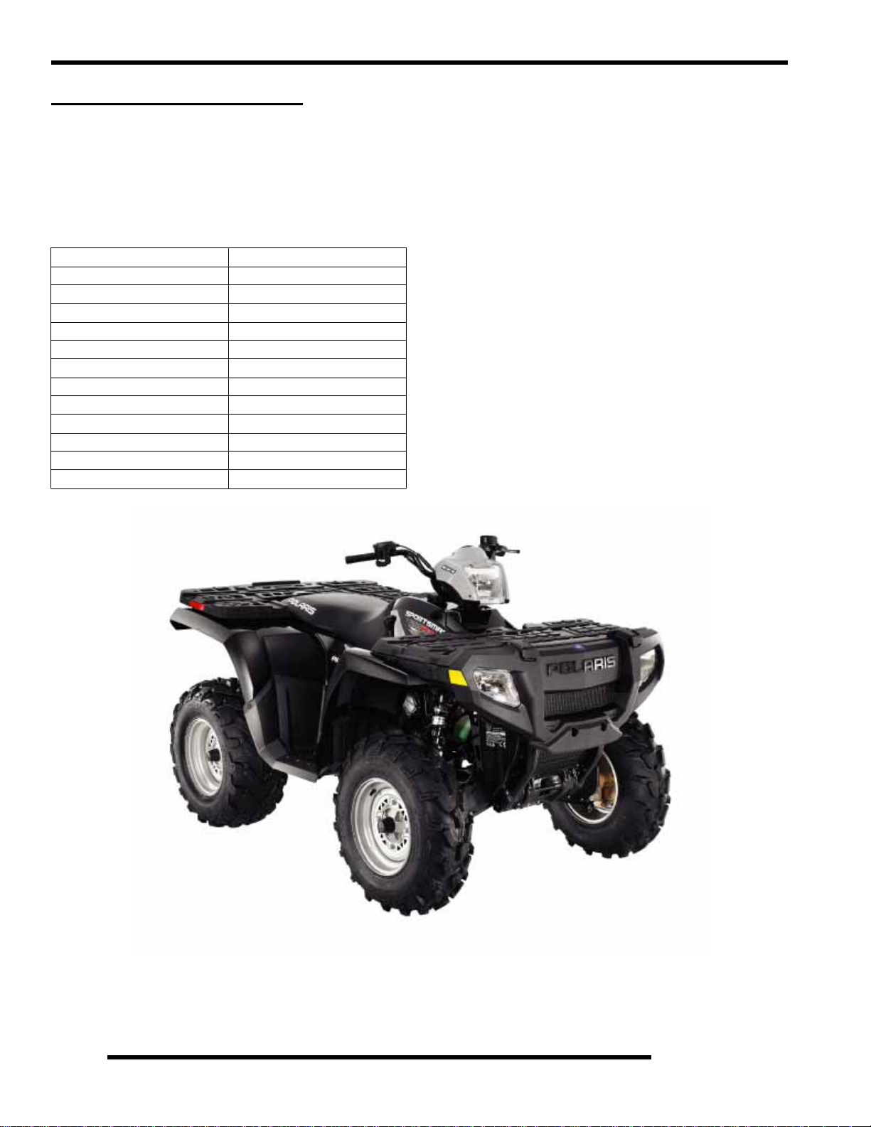
2007 SPORTSMAN 450
Model Number: A07MH46AA, AZ
Engine Model: EH46PLE
Table 1-4: Sportsman 450 General
Specifications
Category Dimension / Capacity
Length 83 in./211 cm
Width 48 in./122 cm
Height 48 in./122 cm
Wheel Base 50.5 in./128.3 cm
Ground Clearance 11 in./27.94 cm
Dry Weight 715 lbs./324 kg
Gross Vehicle Weight 1210 lbs./549 kg
Front Rack Capacity 90 lbs./40.8 kg
Rear Rack Capacity 180 lbs./81.6 kg
Towing Capacity 1225 lbs./555.6 kg
Body Style Spirit
Hitch Tongue Capacity 120 lbs./54.4 kg
1.6
Page 11
GENERAL INFORMATION
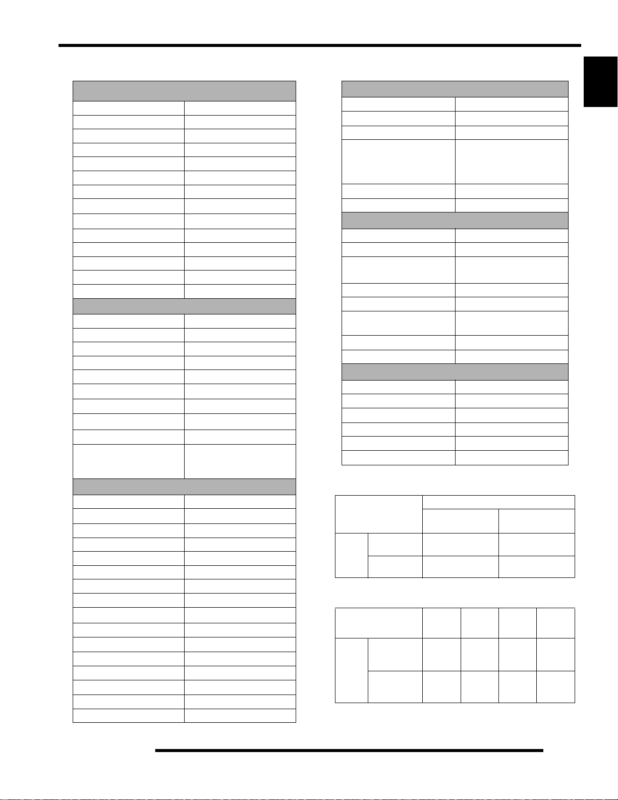
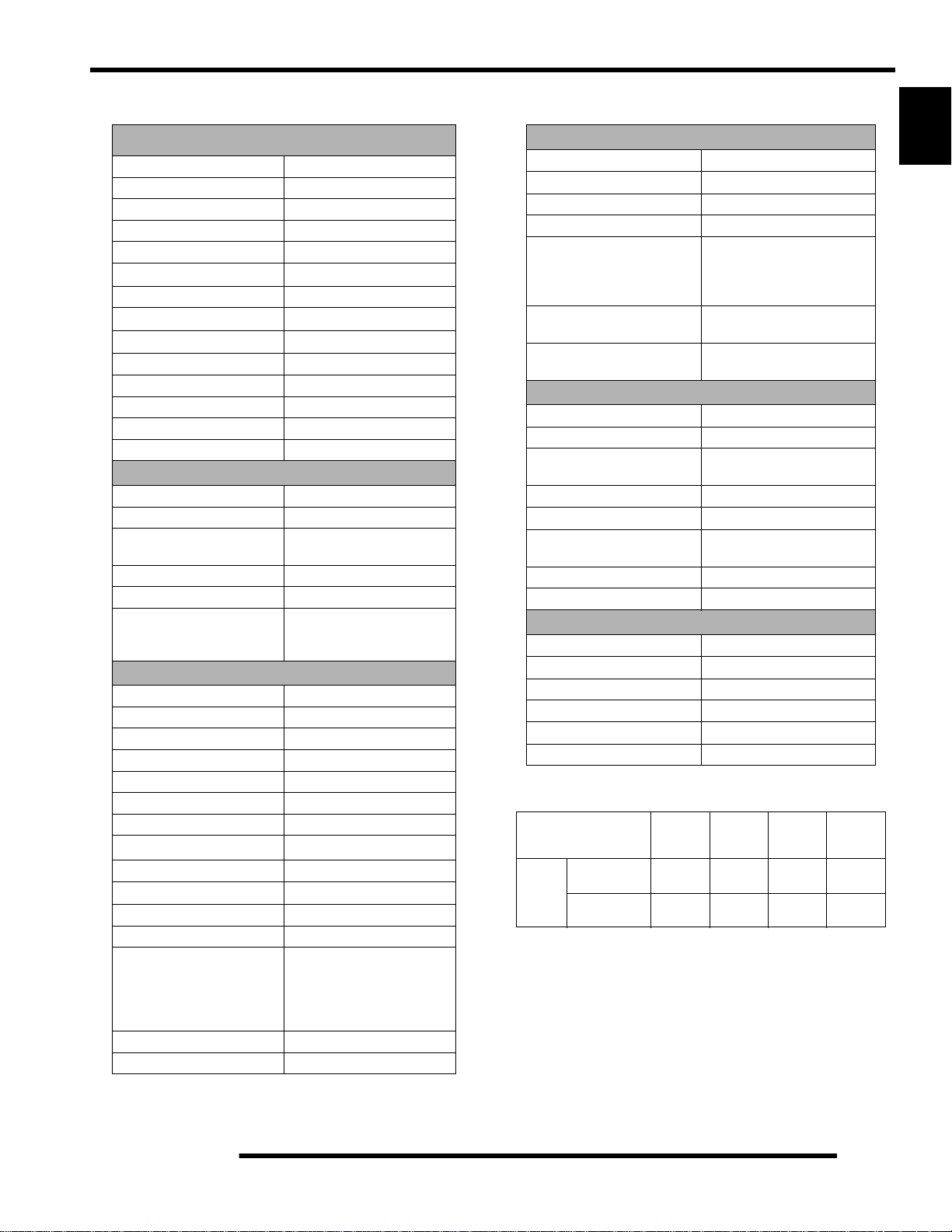
Table 1-5: Sportsman 450
ENGINE
Platform Fuji Single Cylinder
Engine Model Number EH46PL E010
Engine Displacement 455cc
Number of Cylinders 1
Bore & Stroke (mm) 87.9 x 75 mm
Compression Ratio 9.8:1
Compression Pressure 50-90 psi
Engine Idle Speed
Engine Max Operating Rpm
Cooling System / Capacity Liquid - 2.25 qt / 2.1 ltr
Overheat Warning HOT on Instrument Cluster
Lubrication Pressurized Dry Sump
Oil Requirements / Capacity Polaris 0W-40 2 qt. / 1.9 ltr
Exhaust System Single Pipe USFS Approved
Fuel System
Carburetor Mikuni BST 34mm
Main Jet 167.5
Pilot Jet 42.5
Jet Needle / Clip Position 4IB33 - 3
Needle Jet P-6M (829)
Pilot Screw 2 3/4 Turns Out (initial)
Pilot Air Jet 1.3
Float Height
Fuel Delivery Fuel Pump
Fuel Capacity / Requirement 4.25 gal US / 19.9 liters
Electrical
Alternator Output 260 w @ 3000 RPM
Voltage Regulator 3-phase - PDM
Lights : Pod 50 watts
Grill 2 x 37 watts
Brake 26.9 watts
Tail 8.26 watts
Worklight 13 watts
Indicator 1 watt
Operating RPM
Ignition System DC/CDI Ignition
Ignition Timing
Spark plug / Gap BKR6E / .035 in. / 0.9 mm
Battery / Amp Hr Maintenance-Free / 12 Amp Hr.
Circuit Protection Solid State - PDM
Starting Electric / Recoil
Instrument Cluster Analog Speedo w/ LCD
6000 RPM
30
W/Compression Release
1100
50 RPM
6000 Rpm
13mm
87 Octane (minimum)
200 Rpm
1 (.51 0.40")
or 89 Oxygenated
°2° BTDC @ 5000 RPM
Table 1-6: Sportsman 450
Drivetrain
Transmission Type Drumshift - H/L/N/R/P
Transmission Capacity 32 oz. / 948 ml
Front Gearcase Capacity 8.97 oz. / 265 ml
Gear Ratio : Low
Rev
High
Front Drive
Clutch Type PVT Non-EBS
Belt 3211077
23.91:1
16.30:1
10.49:1
3.82:1
Steering / Suspension
Front Suspension / Shock A-arm / MacPherson Strut
Front Travel 8.2 in. / 20.8 cm
Rear Suspension / Shock Progressive Rate Independent -
w/ 2
" Coil-over shock
Rear Travel 9.5 in. / 24.13 cm
Ground Clearance 11 in. / 27.94 cm
Shock Preload Adjustment
Front / Rear
Turning Radius 65 in./165.10 cm unloaded
Toe Out 0-1/16 in / .0 - .159 mm
Front -Non Adjustable.
Rear - Ratchet Style- Std.
Wheels / Brakes
Wheel / Tire Size / Pattern - Front Steel 25x8 - 12 / 4-156
Wheel / Tire Size / Pattern - Rear Steel 25x11 - 12 / 4-156
Recommended Air Pressure Front & Rear - 5 psi
Brake - Front Dual Hydraulic Disc
Brake - Rear Single Hydraulic Disc
Brake Fluid DOT - approved only
Table 1-7: Sportsman 450 Jetting
AMBIENT TEMPERATURE
M e t e r s
(Feet)
Altitude
0-1800
(0-6000)
1800-3700
(6000-12000)
Below 40
Below 5 ° C
° F
+40 to +80 ° F
+5 to +28 ° C
175 167.5
162.5 157.5
Table 1-8: Sportsman 450 Clutching
M e t e r s
(Feet)
Altitude
0-1800
(0-6000)
1800-3700
(6000-12000)
Shift
Weight
10 WH
(5630710)
20-40
(5631356)
Drive
Clutch
Spring
Blu/Grey
(7042202)
Blu/Grey
(7042202)
Driven
Clutch
Spring
Black
(7041782)
Black
(7041782)
Driven-
Helix
40
2+2
(5131446)
40
2+2
(5131446)
1
°
°
1.7
Page 12
GENERAL INFORMATION
2007 SPORTSMAN 500 EFI
Model Number: A07MH50AX, AY, AZ, AQ / A07MN50AL, AF / A07MH50FC
(Standard Models) (Deluxe Models) (International)
Engine Model: EH50PLE
Table 1-9: Sportsman 500 EFI General
Specifications
Category Dimension / Capacity
Length 83 in./211 cm
Width 48 in./122 cm
Height 48 in./122 cm
Wheel Base 50.5 in./128.3 cm
Ground Clearance 11.25 in./28.6 cm
Dry Weight 715 lbs./324 kg
Gross Vehicle Weight 1200 lbs./544 kg
Front Rack Capacity 90 lbs./40.8 kg
Rear Box Capacity 180 lbs./81.6 kg
Towing Capacity 1225 lbs./555.6 kg
Body Style Spirit
Hitch Tongue Capacity 120 lbs./54.4 kg
1.8
Page 13
GENERAL INFORMATION
Table 1-10: Sportsman 500 EFI
ENGINE
Platform Fuji Single Cylinder
Engine Model Number EH50PL E210
Engine Displacement 499cc
Number of Cylinders 1
Bore & Stroke (mm) 92 x 75 mm
Compression Ratio
Compression Pressure 50-90 psi W/Compression Release
Engine Idle Speed
Engine Max Operating Rpm
Cooling System / Capacity Liquid - 2.5 qt / 2.4 ltr
Overheat Warning HOT on Instrument Cluster
Lubrication Pressurized Dry Sump
Oil Requirements / Capacity Polaris 0W-40 2 qt. / 1.9 ltr
Exhaust System Single Pipe USFS Approved
Fuel System
Fuel System Electronic Fuel Injection (EFI)
Fuel Pump (in tank assembly) 25L per hr. at 39 psi
Fuel Filter(s) 10 micron in-line
30 micron in tank Fuel Injector(s) Visteon
EFI Controller Visteon VP5U1U-12A650-AA
Fuel Capacity / Requirement 6 gal US / 22.7 liters
Electrical
Alternator Output 350 w @ 6000 RPM
Lights : Pod 50 watts
Grill 2 x 37 watts
Brake 2 x 8.26 watts
Tail 2 x 26.9 watts
Worklight 2 x 13 watts
Indicator 1 watt
Operating RPM
Ignition System DC/CDI Ignition
Ignition Timing
Spark plug / Gap BKR6E / .035 in. / 0.9 mm
Battery / Amp Hr Lead Acid / 30 Amp Hr.
Circuit Breakers Fan 12 amp / Switched Power 10
Starting Electric / Recoil
Instrument Cluster Analog Speedo w/ LCD
6000 RPM
13
amp / Fuel Pump 10 amp / ECU
15 amp / Ignition Coil 10 amp /
Accessory Power 10 amp /
10.2:1
1100
200 RPM
6000 Rpm
87 Octane (minimum)
200 Rpm
(not replaceable)
or 89 Oxygenated
° BTDC @ 1150 RPM
Lights 20 Amp
Table 1-11: Sportsman 500 EFI
Drivetrain
Transmission Type Drumshift - H/L/N/R/P
Transmission Capacity 32 oz. / 948 ml
Front Gearcase Capacity- CH 8.97 / 265 ml
Front Gearcase Capacity- ADC 9.3 / 275 ml
Gear Ratio : Low
Rev
High
Front Drive
Clutch Type PVT (Standard Models)
PVT w/EBS (Deluxe Models)
Belt 3211113 EBS
23.91:1
21.74:1
10.57:1
3.82:1
3211077 Non-EBS
Steering / Suspension
Front Suspension / Shock A-arm / MacPherson Strut
Front Travel 8.2 in. / 20.8 cm
Rear Suspension / Shock Progressive Rate Independent -
Coil - over shock
Rear Travel 9.5 in. / 24.13 cm
Ground Clearance 11 in. / 27.94 cm
Shock Preload Adjustment
Front / Rear
Turning Radius 65 in./165.10 cm unloaded
Toe Out 0-1/16 in / .0 - .159 mm
Front -Non Adjustable.
Rear - Ratchet Style- Std.
Wheels / Brakes
Wheel/Tire Size / Pattern - Front 26 x 8 - 12 / 4-156
Wheel/Tire Size / Pattern - Rear 26 x 11 - 12 / 4-156
Recommended Air Pressure Front & Rear - 5 psi
Brake - Front Dual Hydraulic Disc
Brake - Rear Single Hydraulic Disc
Brake Fluid DOT - approved only
Table 1-12: Sportsman 500 EFI Clutching
Altitude Shift
M e t e r s
(Feet)
0-1800
(0-6000)
1800-3700
(6000-12000)
Weight
10 WH
(5630710)
10 RH
(5630709)
Drive
Clutch
Spring
Blu/Green
(7041157)
Blu/Green
(7041157)
Driven
Clutch
Spring
White/Yel
(7041635)
White/Yel
(7041635)
Helix*
*No
Adjustment
EBS
(5131674)
EBS
(5131674)
1
1.9
Page 14
GENERAL INFORMATION
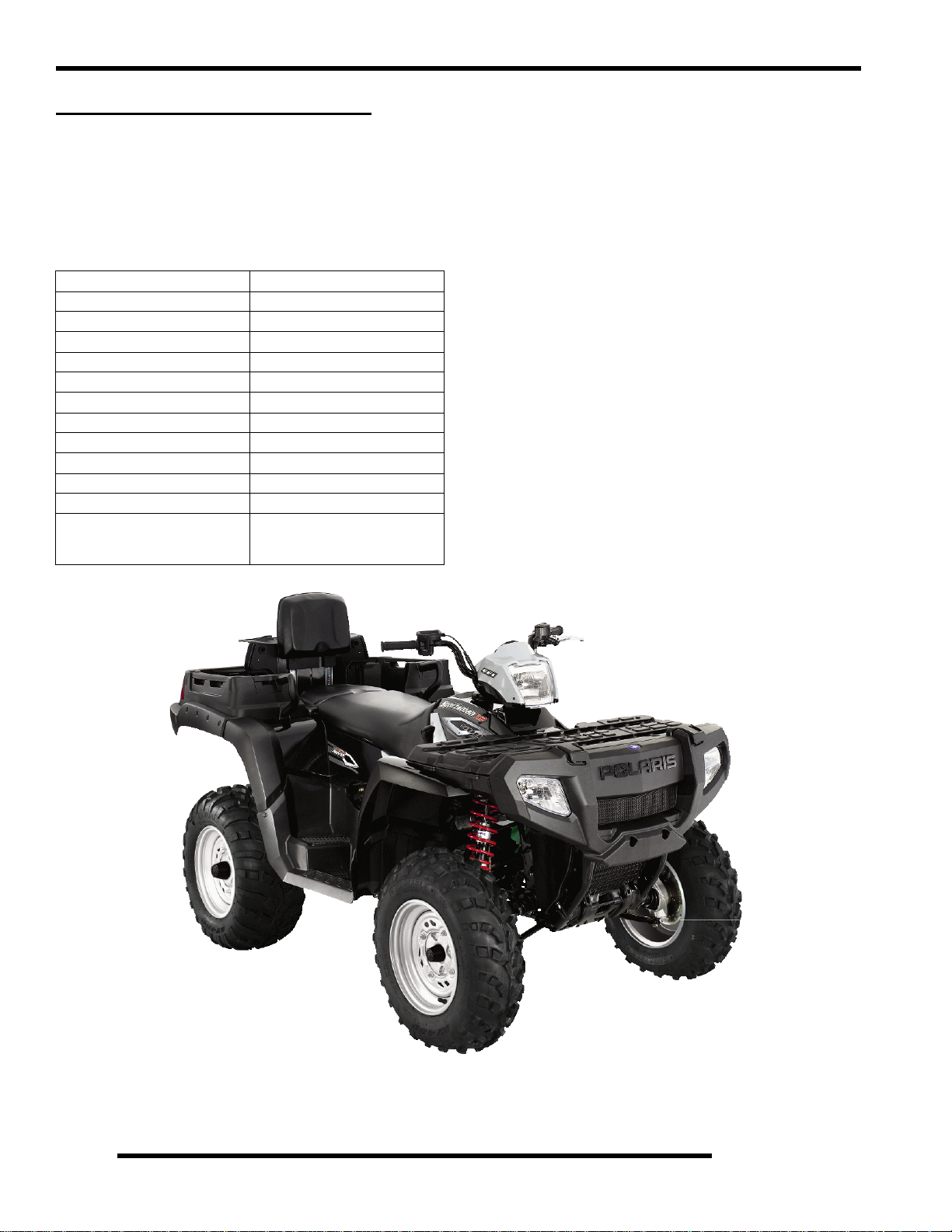
2007 SPORTSMAN X-2 500 EFI
Model Number: A07TH50AU, AZ, AQ / A07TN50AF / A07TH50EA
(Standard Models) (Deluxe Model) (Intl’ Quadricycle)
Engine Model: EH50PLE
Table 1-13: Sportsman X-2 500 EFI General
Specifications
Category Dimension / Capacity
Length 93 in./236 cm
Width 48 in./122 cm
Height 48 in./122 cm
Wheel Base 57 in./145 cm
Ground Clearance 11 in./28 cm
Dry Weight 798 lbs./362 kg
Gross Vehicle Weight 1500 lbs./680 kg
Front Rack Capacity 90 lbs./40.8 kg
Rear Box Capacity 400 lbs./81.6 kg
Towing Capacity 1225 lbs./555.6 kg
Body Style Spirit
Hitch Tongue Capacity 120 lbs./54.4 kg
Rear box capacity and tongue weight
not to exceed 400 lbs./181kg
1.10
Page 15
GENERAL INFORMATION
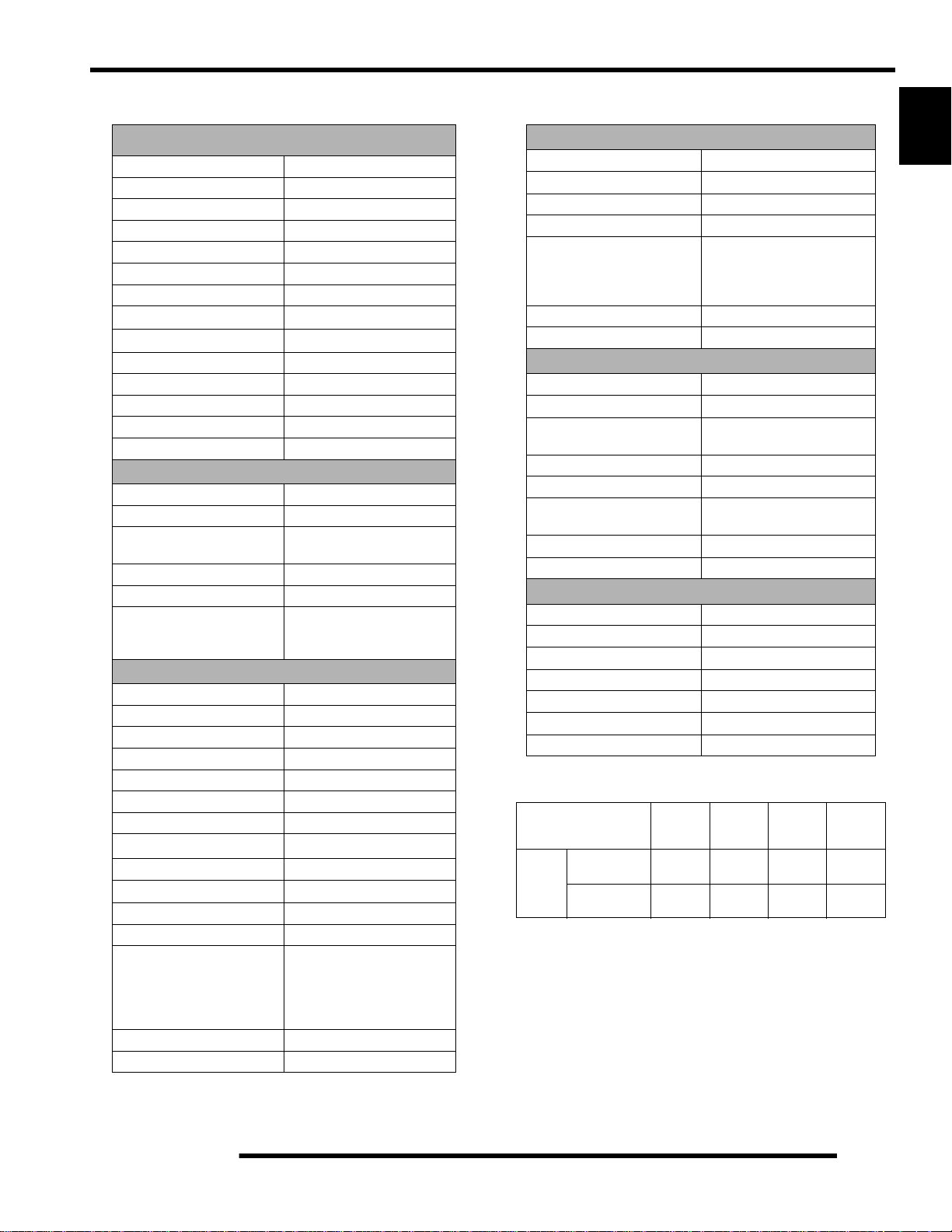
Table 1-14: Sportsman X2 500 EFI
ENGINE
Platform Fuji Single Cylinder
Engine Model Number EH50PL E210
Engine Displacement 499cc
Number of Cylinders 1
Bore & Stroke (mm) 92 x 75 mm
Compression Ratio 10.2:1
Compression Pressure 60-90 psi
Engine Idle Speed
Engine Max Operating Rpm
Cooling System / Capacity Liquid - 2.5 qt / 2.4 ltr
Overheat Warning HOT on Instrument Cluster
Lubrication Pressurized Dry Sump
Oil Requirements / Capacity Polaris 0W-40 2 qt. / 1.9 ltr
Exhaust System Single Pipe USFS Approved
Fuel System
Fuel System Electronic Fuel Injection (EFI)
Fuel Pump (in tank assembly) 25L per hr. at 39 psi
Fuel Filter(s) 10 micron in-line
30 micron in tank Fuel Injector(s) Visteon
EFI Controller Visteon VP5U1U-12A650-AA
Fuel Capacity / Requirement 6 gal US / 22.7 liters
Electrical
Alternator Output 350 w @ 6000 RPM
Lights : Pod 50 watts
Grill 2 x 37 watts
Brake 2 x 8.26 watts
Tail 2 x 26.9 watts
Worklight 2 x 13 watts
Indicator 1 watt
Operating RPM
Ignition System DC/CDI Ignition
Ignition Timing
Spark plug / Gap BKR6E / .035 in. / 0.9 mm
Battery / Amp Hr Lead Acid / 30 Amp Hr.
Circuit Breakers Fan 12 amp / Switched Power 10
Starting Electric / Recoil
Instrument Cluster Analog Speedo w/ LCD
6000 RPM
10
amp / Fuel Pump 10 amp / ECU
15 amp / Ignition Coil 10 amp /
W/Compression Release
1150
50 RPM
6000 Rpm
87 Octane (minimum)
200 Rpm
(not replaceable)
or 89 Oxygenated
° BTDC @ 1150 RPM
Accessory Power 10 amp /
Lights 20 Amp
Table 1-15: Sportsman X2 500 EFI
Drivetrain
Transmission Type Drumshift - H/L/N/Rev/Park
Transmission Capacity 32 oz. / 948 ml
Front Gearcase Capacity- CH 8.97 / 265 ml
Front Gearcase Capacity- ADC 9.3 / 275 ml
Gear Ratio : Low
Rev
High
Front Drive
Clutch Type PVT w/EBS
Belt 3211113
23.91:1
21.74:1
10.57:1
3.82:1
Steering / Suspension
Front Suspension / Shock A-arm / MacPherson Strut
Front Travel 8.2 in. / 20.8 cm
Rear Suspension / Shock Progressive Rate Independent -
Coil - over shock
Rear Travel 8.75 in. / 22.2 cm
Ground Clearance 11 in. / 28 cm
Shock Preload Adjustment
Front / Rear
Turning Radius 82 in./208 cm unlocked
Toe Out 0-1/16 in / .0 - .159 mm
Front -Non Adjustable.
Rear - Ratchet Style- Std.
Wheels / Brakes
Wheel Size / Pattern - Front Steel 12x6 / 4-156
Wheel Size / Pattern - Rear Steel 12x8 / 4-156
Front Tire Size 25x8-12
Rear Tire Size 25x11-12
Recommended Air Pressure Front & Rear - 5 psi
Brake - Front Dual Hydraulic Disc
Brake - Rear Dual Hydraulic Disc
Table 1-16: Sportsman X2 500 EFI
Altitude Shift
M e t e r s
(Feet)
0-1800
(0-6000)
1800-3700
(6000-12000)
Weight
10 WH
(5630710)
10 RH
(5630709)
Drive
Clutch
Spring
Blu/Green
(7041157)
Blu/Green
(7041157)
Driven
Clutch
Spring
White/Yel
(7041635)
White/Yel
(7041635)
Helix*
*No
Adjustment
EBS
(5131674)
EBS
(5131674)
1
1.11
Page 16
GENERAL INFORMATION
MISC. NUMBERS/CHARTS
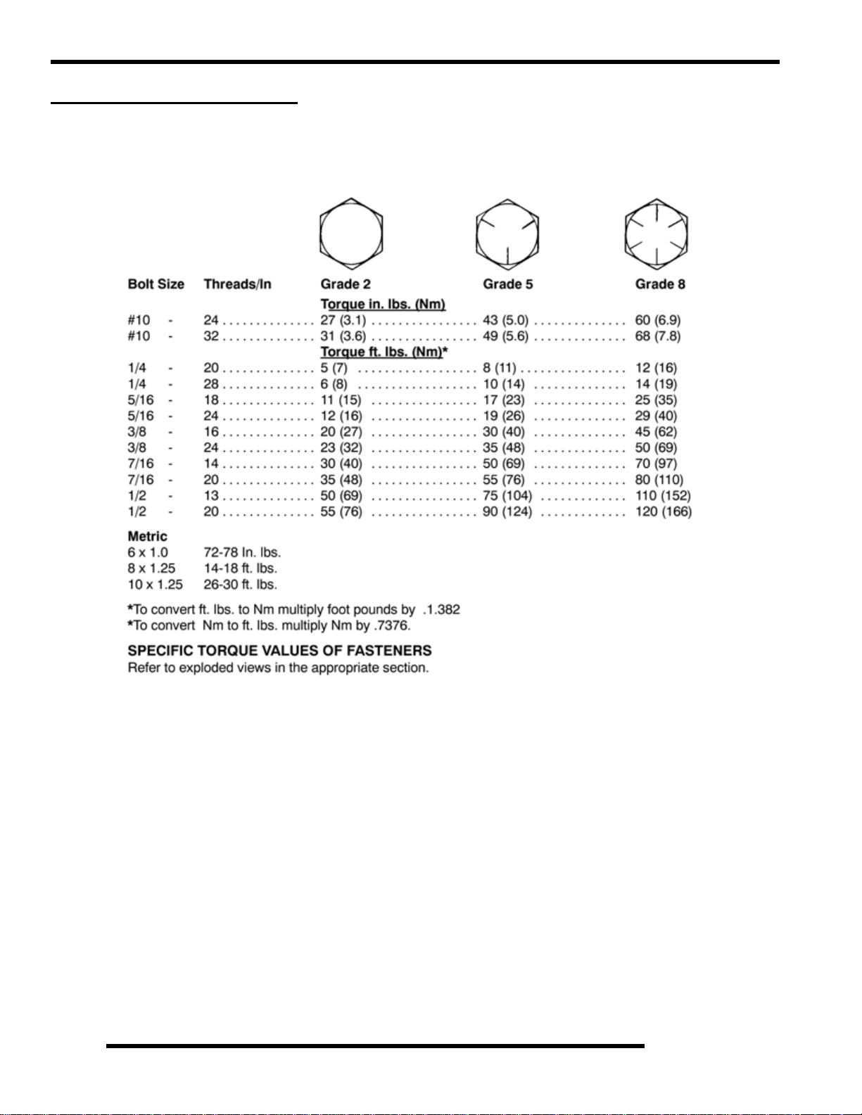
Standard Torque Specifications
The following torque specifications are to be used as a general guideline. There are exceptions in the steering, suspension, and engine
areas. Always consult the exploded views in each manual section for torque values of fasteners before using standard torque.
1.12
Page 17
GENERAL INFORMATION
SAE Tap Drill Sizes
Thread Size/ Drill Size Thread Size / Drill Size
#0-80 3/64 1/2-13 27/64
#1-64 53 1/2-20 29/64
#1-72 53 9/16-12 31/64
#2-56 51 9/16-18 33/64
#2-64 50 5/8-11 17/32
#3-48 5/64 5/8-18 37/64
#3-56 45 3/4-10 21/32
#4-40 43 3/4-16 11/16
#4-48 42 7/8-9 49/64
#5-40 38 7/8-14 13/16
#5-44 37 1-8 7/8
#6-32 36 1-12 59/64
#6-40 33 1 1/8-7 63/64
#8-32 29 1 1/8-12 1 3/64
#8-36 29 1 1/4-7 1 7/64
#10-24 24 1 1/4-12 1 11/64
#10-32 21 1 1/2-6 1 11/32
#12-24 17 1 1/2-12 1 27/64
#12-28 4.6mm 1 3/4-5 1 9/16
1/4-20 7 1 3/4-12 1 43/64
1/4-28 3 2-4 1/2 1 25/32
5/16-18 F 2-12 1 59/64
5/16-24 I 2 1/4-4 1/2 2 1/32
3/8-16 O 2 1/2-4 2 1/4
3/8-24 Q 2 3/4-4 2 1/2
7/16-14 U 3-4 2 3/4
7/16-20 25/64
Metric Tap Drill Sizes
Tap Size Drill Size
3x.50 #39 0.0995 3/32
3x.60 3/32 0.0937 3/32
4x.70 #30 0.1285 1/8
4x.75 1/8 0.125 1/8
5x.80 #19 0.166 11/64
5x.90 #20 0.161 5/32
6x1.00 #9 0.196 13/64
7x1.00 16/64 0.234 15/64
8x1.00 J 0.277 9/32
8x1.25 17/64 0.265 17/64
9x1.00 5/16 0.3125 5/16
9x1.25 5/16 0.3125 5/16
10x1.25 11/32 0.3437 11/32
10x1.50 R 0.339 11/32
11x1.50 3/8 0.375 3/8
12x1.50 13/32 0.406 13/32
12x1.75 13/32 0.406 13/32
Decimal
Equivalent
Nearest
Fraction
Decimal Equivalents
1/64 . . . . . . . . . . .. . . . . . . .0156
1/32 . . . . . . .. . . . . . . .0312 . . 1 mm= .0394"
3/64 . . . . . . . . . . .. . . . . . . .0469
1/16 . . . . . . .. . . . . . . .0625
5/64 . . . . . . . . . . .. . . . . . . .0781 . . 2 mm = .0787"
3/32 . . . . . . .. . . . . . . .0938
7/64 . . . . . . . . . . .. . . . . . . .1094 . . 3 mm =.1181"
1/8 . . . . . . . . .1250
9/64 . . . . . . . . . . .. . . . . . . .1406
5/32 . . . . . . .. . . . . . . .1563 . . 4 mm = .1575"
11/64 . . . . . . . . . . .. . . . . . . .1719
3/16 . . . . . . .. . . . . . . .1875 . . 5mm= .1969"
13/64 . . . . . . . . . . .. . . . . . . .2031
7/32 . . . . . . .. . . . . . . .2188
15/64 . . . . . . . . . . .. . . . . . . .2344 . . 6 mm = .2362"
1/4 . . . . . . . . .25
17/64 . . . . . . . . . . .. . . . . . . .2656 . . 7 mm = .2756"
9/32 . . . . . . .. . . . . . . .2813
19/64 . . . . . . . . . . .. . . . . . . .2969
5/16 . . . . . . .. . . . . . . .3125 . . 8mm= .3150"
21/64 . . . . . . . . . . .. . . . . . . .3281
11/32 . . . . . .. . . . . . . .3438 . . 9 mm = .3543"
23/64 . . . . . . . . . . .. . . . . . . .3594
3/8 . . . . . . . . .375
25/64 . . . . . . . . . . .. . . . . . . .3906 . . 10 mm = .3937"
13/32 . . . . . .. . . . . . . .4063
27/64 . . . . . . . . . . .. . . . . . . .4219 . . 11 mm =.4331"
7/16 . . . . . . .. . . . . . . .4375
29/64 . . . . . . . . . . .. . . . . . . .4531
15/32 . . . . . .. . . . . . . .4688 . . 12 mm = .4724"
31/64 . . . . . . . . . . .. . . . . . . .4844
1/2 . . . . . . . . .5 . . . . . . . . . . . 13mm = .5118"
33/64 . . . . . . . . . . .. . . . . . . .5156
17/32 . . . . . .. . . . . . . .5313
35/64 . . . . . . . . . . .. . . . . . . .5469 . . 14 mm = .5512"
9/16 . . . . . . .. . . . . . . .5625
37/64 . . . . . . . . . . .. . . . . . . .5781 . . 15 mm = .5906"
19/32 . . . . . .. . . . . . . .5938
39/64 . . . . . . . . . . .. . . . . . . .6094
5/8 . . . . . . . . .625 . . . . . . . . . 16mm=. 6299"
41/64 . . . . . . . . . . .. . . . . . . .6406
21/32 . . . . . .. . . . . . . .6563 . . 17 mm =.6693"
43/64 . . . . . . . . . . .. . . . . . . .6719
11/16 . . . . . .. . . . . . . .6875
45/64 . . . . . . . . . . .. . . . . . . .7031 . . 18 mm = .7087"
23/32 . . . . . .. . . . . . . .7188
47/64 . . . . . . . . . . .. . . . . . . .7344 . . 19 mm = .7480"
3/4 . . . . . . . . .75
49/64 . . . . . . . . . . .. . . . . . . .7656
25/32 . . . . . .. . . . . . . .7813 . . 20 mm = .7874"
51/64 . . . . . . . . . . .. . . . . . . .7969
13/16 . . . . . .. . . . . . . .8125 . . 21 mm =.8268"
53/64 . . . . . . . . . . .
27/32 . . . . . .. . . . . . . .8438
55/64 . . . . . . . . . . .. . . . . . . .8594 . . 22 mm = .8661"
7/8 . . . . . . . . .875
57/64 . . . . . . . . . . .. . . . . . . .8906 . . 23 mm = .9055"
29/32 . . . . . .. . . . . . . .9063
59/64 . . . . . . . . . . .. . . . . . . .9219
15/16 . . . . . .. . . . . . . .9375 . . 24 mm = .9449"
61/64 . . . . . . . . . . .. . . . . . . .9531
31/32 . . . . . .. . . . . . . .9688 . . 25 mm = .9843"
63/64 . . . . . . . . . . .. . . . . . . .9844
1. . . . . . . . . . 1.0
. . . . . . . .8281
1
1.13
Page 18

GENERAL INFORMATION
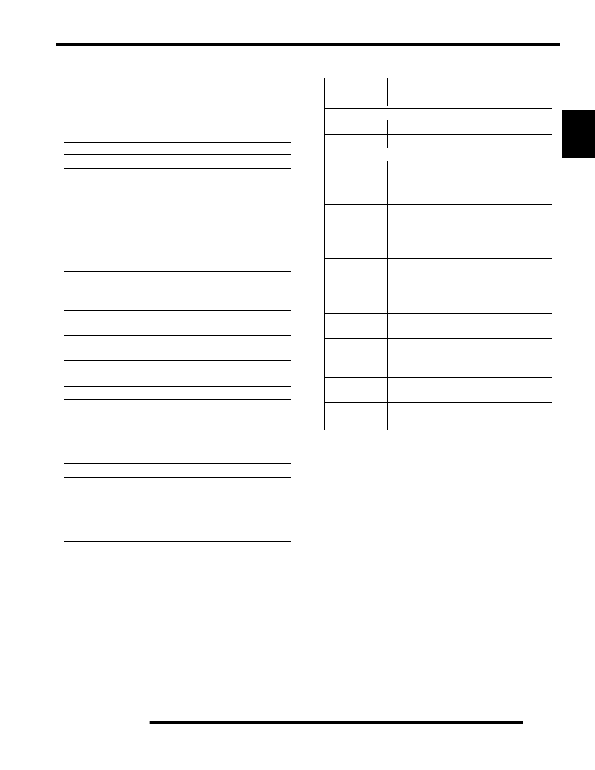
Conversion Table
Unit of Measure Multiplied by Converts to
ft. lbs. x 12 = in. lbs.
in. lbs. x .0833 = ft. lbs.
ft. lbs. x 1.356 = Nm
in. lbs. x .0115 = kg-m
Nm x .7376 = ft. lbs.
kg-m x 7.233 = ft. lbs.
kg-m x 86.796 = in. lbs.
kg-m x 10 = Nm
in. x 25.4 =mm
mm x .03937 = in.
in. x 2.54 = cm
mile (mi.) x 1.6 = km
km x .6214 = mile (mi.)
Ounces (oz.) x 28.35 = Grams (g)
Fluid Ounces (fl. oz.) x 29.57 = Cubic Centimeters (cc)
Cubic Centimeters (cc) x .03381 = Fluid Ounces (fl. oz.)
Grams (g) x 0.035 = Ounces (oz.)
lb. x .454 = kg
kg x 2.2046 = lb.
Cubic inches (cu. in) x 16.387 = Cubic centimeters (cc)
Cubic centimeters (cc) x 0.061 = Cubic inches (cu. in)
Imperial pints (Imp pt.) x 0.568 = Liters (l)
Liters (l) x 1.76 = Imperial pints (Imp pt.)
Imperial quarts (Imp qt.) x 1.137 = Liters (l)
Liters (l) x 0.88 = Imperial quarts (Imp qt.)
Imperial quarts (Imp qt.) x 1.201 = US quarts (US qt.)
US quarts (US qt.) x 0.833 = Imperial quarts (Imp qt.)
US quarts (US qt.) x 0.946 = Liters (l)
Liters (l) x 1.057 = US quarts (US qt.)
US gallons (US gal) x 3.785 =Liters (l)
Liters (l) x 0.264 = US gallons (US gal)
Pounds - force per square inch (psi) x 6.895 = Kilopascals (kPa)
Kilopascals (kPa) x 0.145 = Pounds - force per square inch (psi)
Kilopascals (kPa) x 0.01 = Kilograms - force per square cm
Kilograms - force per square cm x 98.1 = Kilopascals (kPa)
(3.14)xR
2
x H (height) = Cylinder Volume
°C to °F: 9 (°C + 40) 5 - 40 = °F
°F to °C: 5 (°F + 40)
9 - 40 = °C
1.14
Page 19

Glossary Of Terms
GENERAL INFORMATION
ABDC: After bottom dead center.
ACV: Alternating current voltage.
ADC: Active Descent Control.
Alternator: Electrical generator producing voltage alternating current.
ATDC: After top dead center.
BBDC: Before bottom dead center.
BDC: Bottom dead center.
BTDC: Before top dead center.
CC: Cubic centimeters.
Center Distance: Distance between center of crankshaft and center of driven clutch shaft.
Chain Pitch: Distance between chain link pins (No. 35 = 3/8, or 1 cm). Polaris measures chain length in number of pitches.
Crankshaft Run-Out: Run-out or "bend" of crankshaft measured with a dial indicator while crankshaft is supported between
centers on V blocks or resting in crankcase. Measure at various points especially at PTO.
DCV: Direct current voltage.
Electrical Open: Open circuit. An electrical circuit which isn't complete.
Electrical Short: Short circuit. An electrical circuit which is completed before the current reaches the intended load. (i.e. a bare
wire touching the chassis).
Engagement RPM: Engine RPM at which the drive clutch engages to make contact with the drive belt.
ft.: Foot/feet.
Ft. lb. / Foot Pound: A force of one pound at the end of a lever one foot in length, applied in a rotational direction.
g: Gram. Unit of weight in the metric system.
gal.: Gallon.
ID: Inside diameter.
in.: Inch/inches.
Inch Pound: In. lb. 12 in. lbs. = 1 ft. lb.
kg/cm: Kilograms per square centimeter.
kg-m: Kilogram meters.
Kilogram/meter: A force of one kilogram at the end of a lever one meter in length, applied in a rotational direction.
l or ltr: Liter.
Left Side: Always referred to based on normal operating position of the driver.
m: Meter/meters.
Mag: Magneto.
Magnetic Induction: As a conductor (coil) is moved through a m agnetic field, a voltage will be generated in the windings.
Mechanical energy is converted to electrical energy in the stator.
mi.: Mile/miles.
mm: Millimeter. Unit of length in the metric system. 1mm = approximately .040,.
Nm: Newton meters.
OD: Outside diameter.
Ohm: The unit of electrical resistance opposing current flow.
oz.: Ounce/ounces.
PDM: Power Distribution Module.
Piston Clearance: Total distance between piston and cylinder wall.
psi.: Pounds per square inch.
PTO: Power take off.
qt.: Quart/quarts.
RPM:
Revolutions per minute.
Regulator: Voltage regulator. Regulates battery charging system output at approx. 14.5 DCV as engine RPM increases.
Resistance: In the mechanical sense, friction or load. In the electrical sense, ohms. Both result in energy conversion to heat.
Right Side: Always referred to based on normal operating position of the driver.
RPM: Revolutions per minute.
Seized Piston: Galling of the sides of a piston. Usually there is a transfer of aluminum from the piston onto the cylin der wall.
Possible causes: 1) improper lubrication; 2) excessive temperatures; 3) insufficient piston clearance; 4) stuck piston rings.
Stator Plate: The plate mounted under the flywheel supporting the battery charging coils.
TDC: Top dead center. Piston's most outward travel from crankshaft.
Volt: The unit of measure for electrical pressure of electromotive force. Measured by a voltmeter in parallel with the circuit.
Watt: Unit of electrical power. Watts = amperes x volts.
WOT: Wide open throttle.
1
1.15
Page 20

GENERAL INFORMATION
NOTES
1.16
Page 21

MAINTENANCE
CHAPTER 2
MAINTENANCE
MAINTENANCE. . . . . . . . . . . . . . . . . . . . . . . . . . . . . . . . . . . . . . . . . . . . . . . . . . . . . . . . . 2.3
PERIODIC MAINTENANCE CHART . . . . . . . . . . . . . . . . . . . . . . . . . . . . . . . . . . . . . . . .2.3
MAINTENANCE CHART KEY . . . . . . . . . . . . . . . . . . . . . . . . . . . . . . . . . . . . . . . . . . . . .2.3
PERIODIC MAINTENANCE CHART . . . . . . . . . . . . . . . . . . . . . . . . . . . . . . . . . . . . . . . .2.4
LUBRICATION / FLUIDS. . . . . . . . . . . . . . . . . . . . . . . . . . . . . . . . . . . . . . . . . . . . . . . . . . 2.7
SPORTSMAN COMPONENT LOCATIONS. . . . . . . . . . . . . . . . . . . . . . . . . . . . . . . . . . .2 .7
SPORTSMAN X2 COMPONENT LOCATIONS . . . . . . . . . . . . . . . . . . . . . . . . . . . . . . . .2.8
POLARIS LUBRICANTS, MAINTENANCE AND SERVICE PRODUCTS . . . . . . . . . . . .2.9
POLARIS LUBRICANT SYMBOL IDENTIFICATION. . . . . . . . . . . . . . . . . . . . . . . . . . .2.10
PRE-RIDE / DAILY INSPECTION . . . . . . . . . . . . . . . . . . . . . . . . . . . . . . . . . . . . . . . . .2.10
LUBRICATION COMPONENTS. . . . . . . . . . . . . . . . . . . . . . . . . . . . . . . . . . . . . . . . . . .2.11
FRONT GEARCASE LUBRICATION. . . . . . . . . . . . . . . . . . . . . . . . . . . . . . . . . . . . . . .2.12
TRANSMISSION LUBRICATION. . . . . . . . . . . . . . . . . . . . . . . . . . . . . . . . . . . . . . . . . .2.13
ADC DIFFERENTIAL HYDRAULIC CIRCUIT FLUID CHANGE. . . . . . . . . . . . . . . . . . .2.14
VEHICLE INSPECTION. . . . . . . . . . . . . . . . . . . . . . . . . . . . . . . . . . . . . . . . . . . . . . . . . . 2.14
SHIFT LINK ROD INSPECTION. . . . . . . . . . . . . . . . . . . . . . . . . . . . . . . . . . . . . . . . . . .2.14
THROTTLE INSPECTION . . . . . . . . . . . . . . . . . . . . . . . . . . . . . . . . . . . . . . . . . . . . . . .2.15
THROTTLE CABLE / ELECTRONIC THROTTLE CONTROL ADJUSTMENT . . . . . . .2.15
FUEL SYSTEM. . . . . . . . . . . . . . . . . . . . . . . . . . . . . . . . . . . . . . . . . . . . . . . . . . . . . . . .2.16
FUEL LINES . . . . . . . . . . . . . . . . . . . . . . . . . . . . . . . . . . . . . . . . . . . . . . . . . . . . . . . . . .2.16
VENT LINES. . . . . . . . . . . . . . . . . . . . . . . . . . . . . . . . . . . . . . . . . . . . . . . . . . . . . . . . . .2.16
FUEL FILTER. . . . . . . . . . . . . . . . . . . . . . . . . . . . . . . . . . . . . . . . . . . . . . . . . . . . . . . . .2.17
COMPRESSION TEST. . . . . . . . . . . . . . . . . . . . . . . . . . . . . . . . . . . . . . . . . . . . . . . . . .2.17
ENGINE MOUNTS . . . . . . . . . . . . . . . . . . . . . . . . . . . . . . . . . . . . . . . . . . . . . . . . . . . . .2.17
SPARK PLUG. . . . . . . . . . . . . . . . . . . . . . . . . . . . . . . . . . . . . . . . . . . . . . . . . . . . . . . . .2.18
ACTIVE DESCENT CONTROL (ADC) RESERVOIR LEVEL. . . . . . . . . . . . . . . . . . . . . 2.18
BATTERY MAINTENANCE . . . . . . . . . . . . . . . . . . . . . . . . . . . . . . . . . . . . . . . . . . . . . .2.18
LIQUID COOLING SYSTEM OVERVIEW . . . . . . . . . . . . . . . . . . . . . . . . . . . . . . . . . . .2.19
COOLANT STRENGTH / TYPE. . . . . . . . . . . . . . . . . . . . . . . . . . . . . . . . . . . . . . . . . . .2.19
COOLING SYSTEM HOSES . . . . . . . . . . . . . . . . . . . . . . . . . . . . . . . . . . . . . . . . . . . . .2.19
RADIATOR/GRILL SCREEN . . . . . . . . . . . . . . . . . . . . . . . . . . . . . . . . . . . . . . . . . . . . .2.19
COOLING SYSTEM PRESSURE TEST. . . . . . . . . . . . . . . . . . . . . . . . . . . . . . . . . . . . .2.20
COOLANT LEVEL INSPECTION . . . . . . . . . . . . . . . . . . . . . . . . . . . . . . . . . . . . . . . . . .2.20
RADIATOR COOLANT LEVEL INSPECTION . . . . . . . . . . . . . . . . . . . . . . . . . . . . . . . .2.20
AIR FILTER/PRE-FILTER SERVICE . . . . . . . . . . . . . . . . . . . . . . . . . . . . . . . . . . . . . . .2.20
AIR BOX SEDIMENT TUBE. . . . . . . . . . . . . . . . . . . . . . . . . . . . . . . . . . . . . . . . . . . . . .2.21
BREATHER FILTER INSPECTION . . . . . . . . . . . . . . . . . . . . . . . . . . . . . . . . . . . . . . . .2.22
BREATHER HOSE. . . . . . . . . . . . . . . . . . . . . . . . . . . . . . . . . . . . . . . . . . . . . . . . . . . . .2.22
RECOIL HOUSING. . . . . . . . . . . . . . . . . . . . . . . . . . . . . . . . . . . . . . . . . . . . . . . . . . . . .2.22
ENGINE OIL LEVEL. . . . . . . . . . . . . . . . . . . . . . . . . . . . . . . . . . . . . . . . . . . . . . . . . . . .2.23
OIL AND FILTER CHANGE . . . . . . . . . . . . . . . . . . . . . . . . . . . . . . . . . . . . . . . . . . . . . .2.23
OIL PUMP PRIMING PROCEDURE . . . . . . . . . . . . . . . . . . . . . . . . . . . . . . . . . . . . . . .2.25
VALVE CLEARANCE . . . . . . . . . . . . . . . . . . . . . . . . . . . . . . . . . . . . . . . . . . . . . . . . . . .2.25
INTAKE VALVE CLEARANCE ADJUSTMENT . . . . . . . . . . . . . . . . . . . . . . . . . . . . . . .2.26
EXHAUST VALVE CLEARANCE ADJUSTMENT . . . . . . . . . . . . . . . . . . . . . . . . . . . . .2.26
STEERING . . . . . . . . . . . . . . . . . . . . . . . . . . . . . . . . . . . . . . . . . . . . . . . . . . . . . . . . . . .2.26
TIE ROD END/STEERING INSPECTION . . . . . . . . . . . . . . . . . . . . . . . . . . . . . . . . . . .2.27
CAMBER AND CASTER . . . . . . . . . . . . . . . . . . . . . . . . . . . . . . . . . . . . . . . . . . . . . . . .2.27
WHEEL ALIGNMENT. . . . . . . . . . . . . . . . . . . . . . . . . . . . . . . . . . . . . . . . . . . . . . . . . . .2.27
TOE ALIGNMENT ADJUSTMENT. . . . . . . . . . . . . . . . . . . . . . . . . . . . . . . . . . . . . . . . .2.28
EXHAUST PIPE . . . . . . . . . . . . . . . . . . . . . . . . . . . . . . . . . . . . . . . . . . . . . . . . . . . . . . .2.28
BRAKE SYSTEM INSPECTION. . . . . . . . . . . . . . . . . . . . . . . . . . . . . . . . . . . . . . . . . . .2.29
BRAKE PAD INSPECTION . . . . . . . . . . . . . . . . . . . . . . . . . . . . . . . . . . . . . . . . . . . . . .2.30
HOSE/FITTING INSPECTION . . . . . . . . . . . . . . . . . . . . . . . . . . . . . . . . . . . . . . . . . . . .2.30
2
2.1
Page 22

MAINTENANCE
AUXILIARY BRAKE TESTING. . . . . . . . . . . . . . . . . . . . . . . . . . . . . . . . . . . . . . . . . . . .2.30
AUXILIARY BRAKE ADJUSTMENT (HYDRAULIC) . . . . . . . . . . . . . . . . . . . . . . . . . . . 2.30
SUSPENSION SPRING PRELOAD ADJUSTMENT . . . . . . . . . . . . . . . . . . . . . . . . . . . 2.31
FRONT SUSPENSION. . . . . . . . . . . . . . . . . . . . . . . . . . . . . . . . . . . . . . . . . . . . . . . . . . 2.31
CV SHAFT BOOT INSPECTION . . . . . . . . . . . . . . . . . . . . . . . . . . . . . . . . . . . . . . . . . . 2.31
CONTROLS . . . . . . . . . . . . . . . . . . . . . . . . . . . . . . . . . . . . . . . . . . . . . . . . . . . . . . . . . . 2.31
WHEELS. . . . . . . . . . . . . . . . . . . . . . . . . . . . . . . . . . . . . . . . . . . . . . . . . . . . . . . . . . . . .2.31
WHEEL, HUB, AND SPINDLE TORQUE TABLE. . . . . . . . . . . . . . . . . . . . . . . . . . . . . .2.32
WHEEL REMOVAL FRONT OR REAR . . . . . . . . . . . . . . . . . . . . . . . . . . . . . . . . . . . . . 2.32
WHEEL INSTALLATION . . . . . . . . . . . . . . . . . . . . . . . . . . . . . . . . . . . . . . . . . . . . . . . . 2.32
TIRE PRESSURE. . . . . . . . . . . . . . . . . . . . . . . . . . . . . . . . . . . . . . . . . . . . . . . . . . . . . . 2.32
TIRE INSPECTION. . . . . . . . . . . . . . . . . . . . . . . . . . . . . . . . . . . . . . . . . . . . . . . . . . . . . 2.33
FRAME, NUTS, BOLTS, FASTENERS . . . . . . . . . . . . . . . . . . . . . . . . . . . . . . . . . . . . .2.33
STORAGE COMPARTMENTS. . . . . . . . . . . . . . . . . . . . . . . . . . . . . . . . . . . . . . . . . . . . 2.33
WINCH OPERATION (IF EQUIPPED). . . . . . . . . . . . . . . . . . . . . . . . . . . . . . . . . . . . . .2.34
ATV CLEANING & STORAGE . . . . . . . . . . . . . . . . . . . . . . . . . . . . . . . . . . . . . . . . . . . .2.36
MAINTENANCE SCHEDULE. . . . . . . . . . . . . . . . . . . . . . . . . . . . . . . . . . . . . . . . . . . . .2.38
2.2
Page 23
MAINTENANCE
MAINTENANCE
Periodic Maintenance Chart
Careful periodic maintenance will help keep your vehicle in the safest, most reliable condition. Inspection, adjustment and lubrication
of important components are explained in the periodic maintenance chart.
Inspect, clean, lubricate, adjust and replace parts as necessary. When inspection reveals the need for replacement
parts, use genuine Polaris parts available from your Polaris dealer.
NOTE: Service and adjustments are critical. If you’re not familiar with safe service and adjustment procedures, have a
qualified dealer perform these operatio ns.
Maintenance intervals in the following chart are based upon average riding conditions and an average vehicle speed of approximately
10 miles per hour. Vehicles subjected to severe use must be inspected and serviced more frequently.
Severe Use Definition
• Frequent immersion in mud, water or sand
• Racing or race-style high RPM use
• Prolonged low speed, heavy load operation
• Extended idle
• Short trip cold weather operation
Pay special attention to the oil level. A rise in oil level during cold weather can ind icate contaminants collecting in the
oil sump or crankcase. Change oil immediately if the oil level begins to rise. Monitor the oil level, and if it continues to
rise, discontinue use and determin e th e cau se or se e you r dea ler.
Maintenance Chart Key
The following symbols denote potential items to be aware of during maintenance :
= CAUTION: Due to the nature of these adjustments, it is recommended this service be performed by an
authorized Polaris dealer.
= SEVERE USE ITEM --If vehicle is subjected to severe use, decrease interval by 50%
(Severe Use is defined as frequent vehicle immersion in mud, water or sand, racing or race-style high rpm
use, prolonged low speed - heavy load operation or e xte nded idle. M ore preven tat ive maint ena nce is r equire d
under these conditions. Fluid changes, cable and chassis lubrication are required more frequently. For
engine oil, short trip cold weather riding also constitutes se vere use. Pay specia l attention to oil lev el. A rising
oil level in cold weather can indicate contaminants collecting in the oil sump or crankcase. Change oil immediately and monitor level. If oil level begins to rise, discontinue use and determine cause.)
2
E= Emission Control System Service (California).
NOTE: Inspection may reveal the need for replacement parts. Always use genuine Polaris parts.
WARNING
Improperly performing the procedures marked with
a
could result in component failure and lead to
serious injury or death. Have an authorized Polaris
dealer perform these services.
2.3
Page 24
MAINTENANCE
Periodic Maintenance Chart
Item Maintenance Interval
(whichever comes first)
Hours Calendar Miles
(KM)
Steering - Pre-Ride -
Front-suspension - Pre-Ride -
Rear-suspension - Pre-Ride -
Tires - Pre-Ride Brake fluid level - Pre-Ride -
Brake lever travel - Pre-Ride -
Brake systems - Pre-Ride Wheels /fasteners - Pre-Ride Frame fasteners - Pre-Ride -
Engine oil level - Pre-Ride -
E
Passenger Seat Lock Out - Pre-Ride - Verify Seat is secured
Dump Box Operation - Pre-Ride - Verify Box is latched
Air filter, pre-filter - Daily - Inspect; clean often
E
Air box sediment tube - Daily - Drain deposits when visible
E
Coolant - Daily -
Headlamp/tail lamp - Daily Air filter,
main element
E
Recoil housing - Weekly -
Brake pad wear 10 H Monthly 60 (100) Inspect periodically
Battery 20 H Monthly 125 (200) Check terminals; clean; test
Front gearcase oil (if
equipped)
Middle gearcase oil (if
equipped)
Rear gearcase oil
(if equipped)
Transmission oil 25 H Monthly 155 (250) Inspect level; change yearly
- Weekly - Inspect; replace as needed
25 H Monthly 155 (250) Inspect level; change yearly
25 H Monthly 155 (250) Inspect level; change yearly
25 H Monthly 155 (250) Inspect level; change yearly
Make adjustments as needed.
Check level daily, change coolant every 2
years
Check operation; apply dielectric grease if
replacing
Drain water as needed, check often if
operating in wet conditions
Remarks
Perform these procedures more often for vehicles subjected to severe use.
E Emission Control System Service (California)
Have an authorized Polaris dealer perform these services.
2.4
Page 25
Periodic Maintenance Chart
MAINTENANCE
Item Maintenance Interval
(whichever comes first)
Hours Calendar Miles
(KM)
Engine breather
filter (if equipped)
E
Engine oil change
(break-in)
E
General
lubrication
Shift Linkage 50 H 6 M 310 (500) Inspect, lubricate, adjust
Steering 50 H 6 M 310 (500) Lubricate
Front suspension 50 H 6 M 310 (500) Lubricate
Rear suspension 50 H 6 M 310 (500) Lubricate
Throttle Cable/ETC
E
Switch
Air intake ducts/
E
flange
Drive belt 50 H 6 M 310 (500) Inspect; adjust; replace as needed
Cooling system
(if applicable)
Engine oil change
E
Oil filter change 100 H 6 M 620 (1000) Replace with oil change
E
Oil tank vent hose 100 H 12 M 620 (1000) Inspect routing, condition
E
Valve clearance 100 H 12 M 620 (1000) Inspect; adjust
E
25 H Monthly 155 (250) Inspect; replace if necessary
25 H 1 M 155 (250)
50 H 3 M 310 (500)
50 H 6 M 310 (500)
50 H 6 M 310 (500)
50 H 6 M 310 (500)
100 H 6 M 620 (1000)
Perform a break-in oil change at one
month
Lubricate all grease fittings, pivots,
cables, etc.
Inspect; adjust; lubricate; replace if
necessary
Inspect ducts for proper sealing/air
leaks
Inspect coolant strength seasonally;
pressure test system yearly
Perform a break-in oil change at 25
hours/one month
Remarks
2
Perform these procedures more often for vehicles subjected to severe use.
E Emission Control System Service (California)
Have an authorized Polaris dealer perform these services.
2.5
Page 26

MAINTENANCE
Periodic Maintenance Chart
Item Maintenance Interval
(whichever comes first)
Hours Calendar Miles
(Km)
Fuel system 100 H 12M
E
Fuel Filter 100 H 12M
E
Radiator
(if applicable)
Cooling hoses
(if applicable)
Engine mounts 100 H 12M
Exhaust muffler /
pipe
Spark plug 100 H 12M
E
Ignition Timing 100 H 12M
E
Wiring 100 H 12M
Clutches (drive
and driven)
Front wheel
bearings
Brake fluid 200 H 24M
Spark arrestor 300 H 36M
Toe adjustment - Inspect periodically; adjust when part s are replaced
Auxiliary brake - Inspect daily; adjust as needed
Headlight aim - Adjust as needed
100 H 12M
100 H 12M
100 H 12M
100 H 12M
100 H 12M
620
(1000)
620
(1000)
620
(1000)
620
(1000)
620
(1000)
620
(1000)
620
(1000)
620
(1000)
620
(1000)
620
(1000)
1000
(1600)
1240
(2000)
1860
(3000)
Check for leaks at tank cap, lines, fuel valve, filter,
pump, carburetor; replace lines every two years
Replace yearly
Inspect; clean external surfaces
Inspect for leaks
Inspect
Inspect
Inspect; replace as needed
Inspect
Inspect for wear, routing, security; apply dielectric
grease to connectors subjected to water, mud, etc.
Inspect; clean; replace worn parts
Inspect; replace as needed
Change every two years
Clean out
Remarks
Perform these procedures more often for vehicles subjected to severe use.
E Emission Control System Service (California)
Have an authorized Polaris dealer perform these services.
2.6
Page 27
LUBRICATION / FLUIDS
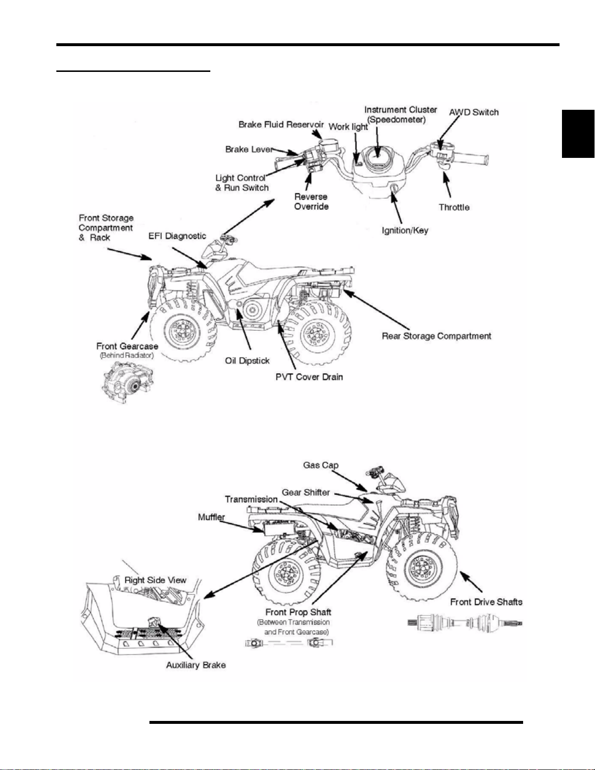
SPORTSMAN Component Locations
MAINTENANCE
(Deluxe)
2
(Sportsman Only)
2.7
Page 28
MAINTENANCE
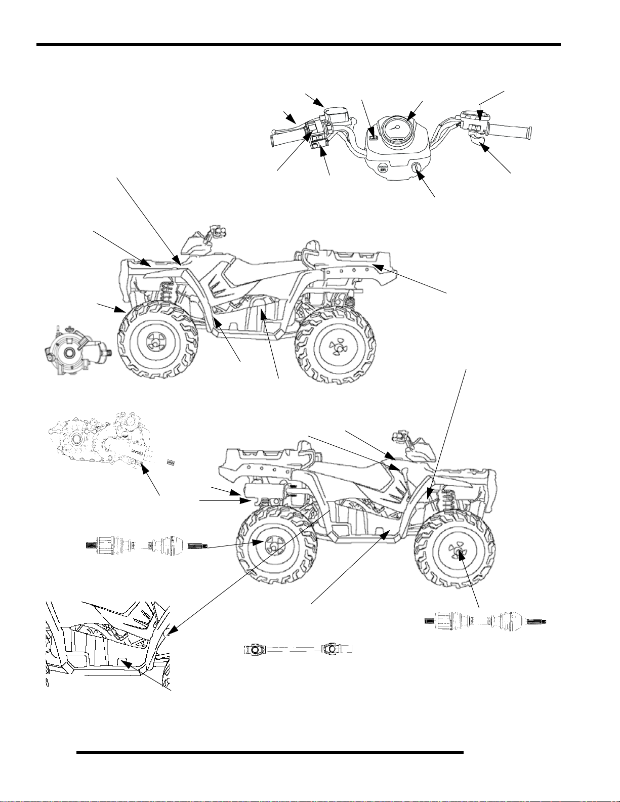
SPORTSMAN X2 Component locations
Brake Fluid Reservoir
Brake Lever
Worklight
Instrument Cluster
(Speedometer)
AWD/Turf Switch
Diagnostic
Port (under access panel)
Front St orage
Compartment
& Rack
Front Demand
Drive Unit
(Behind Radiator)
Light Control
& Run Switch
Oil Dipstick
PVT Cover
Gear Shifter
Reverse
Override
Gas Cap
Throttle
Ignition/Key
Rear Dump Box / Passenger Area
Battery (Under Tank)
2.8
Transmission
Rear Drive CV Shafts
Right Side View
Muffler
Auxiliary Brake
Front Prop Shaft
(Between Transmission
and Front Gearcase)
Front Drive CV Shafts
Page 29
MAINTENANCE
Polaris Lubricants, Maintenance and Service Products
Table 2-1:
PART
NUMBER
Engine Lubricant
2870791 Fogging Oil (12 oz. Aerosol)
2871281
2871844
2871567
Gearcase / Transmission Lubricants
2876251 Demand Drive L T Premium Hub Fluid
3234438 Polaris ADC Hydraulic Fluid
2873602
2873603
2876160
2872276
2870465 Oil Pump for 1 Gallon Jug
2871322
2871423
2871460 Starter Drive Grease (12 count)
2871515
2871551
2871312 Grease Gun Kit
2871329
Engine Oil (Quart) Premium Synthetic
Engine Oil (Gallon) Premium Synthetic
Engine Oil (16 Gallon) Premium 4
Premium Synthetic AGL Gearcase Lube
Premium Synthetic AGL Gearcase Lube
Premium ATV Angle Drive Fluid
Premium ATV Angle Drive Fluid
Grease / Specialized Lubricants
DESCRIPTION
0W-40 (4-cycle) (12 count)
0W-40 (4-cycle) (4 count)
Synthetic 0W-40 (4-cycle)
(12 oz. bottle) (12 count)
(1 Gal. bottle) (4 count)
(32 oz.) (12 count)
(2.5 Gal.) (2 count)
Premium All Season Grease
(3 oz. cartridge) (24 count)
Premium All Season Grease
(14 oz. cartridge) (10 count)
Premium U-Joint Lube
(3 oz.) (24 Count)
Premium U-Joint Lube
(14 oz.) (10 count)
Dielectric Grease (Nyogel
Table 2-1:
PART
NUMBER
2871323 60/40 Coolant (Gallon) (6 count)
2871534 60/40 Coolant (Quart) (12 count)
Additives / Sealants / Thread Locking Agents / Misc.
2874275
2871956
2871950
2871951
2871953
2871557
2871326
2870652 Fuel Stabilizer (16 oz.) (12 count)
2871957
2871958
2870990 DOT 3 Brake Fluid (12 count)
2871557 Crankcase Sealant, 3 Bond 1215 (5 oz.)
DESCRIPTION
Coolant
Loctite
Primer N, Aerosol
Loctite
Thread Sealant 565
(50 ml.) (6 count)
Loctite
Threadlock 242
(6 ml.) (12 count)
Loctite
Threadlock 262
(50 ml.) (10 count)
Loctite
Threadlock 271
(6 ml.) (12 count)
3-Bond 1215
Premium Carbon Clean
(12 oz.) (12 count)
Black RTV Silicone Sealer
(3 oz. tube ) (12 count)
Black RTV Silicone Sealer
(11 oz. cartridge) (12 count)
Sealant
(5 oz.)
2
2.9
Page 30
MAINTENANCE
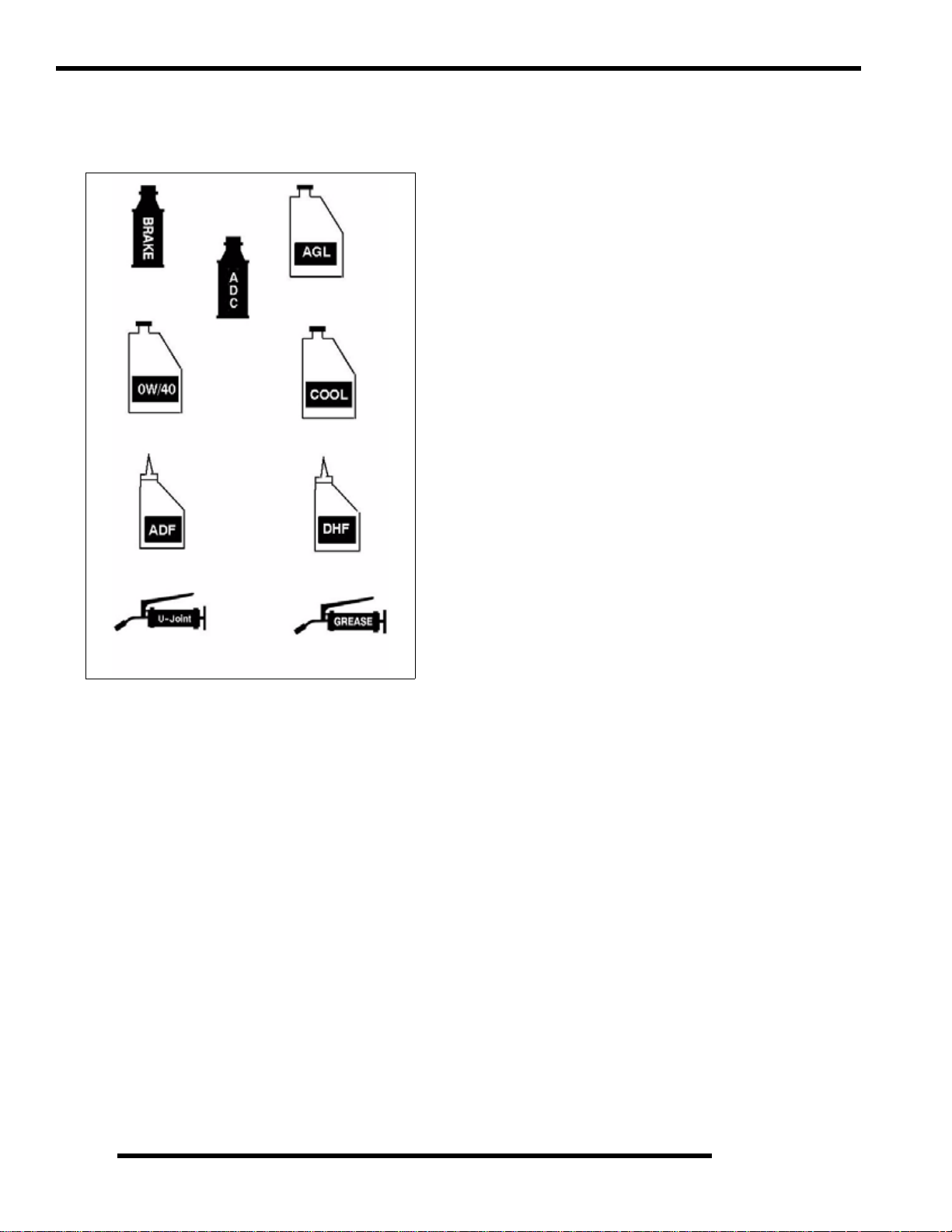
Polaris Lubricant Symbol Identification
NOTE: The symbols used are for quick reference in identifying
which lubricant/grease to use on each component.
Polaris DOT
Brake Fluid
Polaris ADC
Hydraulic Fluid
Polaris Synthetic
0W/40
Polaris ATV Angle
Drive Fluid
Polaris Synthetic AGL
Gearcase Lube
Polaris 60/40
Coolant
Polaris Demand Drive
LT Hub Fluid
Pre-ride / Daily Inspection
Perform the following pre-ride inspection daily, and when
servicing the vehicle at each scheduled maintenance.
• Verify seat lock-out operation
• Verify box lock-out operation
• Tires - check condition and pressures
• Fuel and oil tanks - fill both tanks to their proper level;
Do not overfill oil tank
• All brakes - check operation and adjustment (includes
auxiliary brake)
• Throttle -check for free operation
• Headlight/Taillight/Brakelight - check operation of all
indicator lights and switches
• Engine stop switch - check for proper function
• Wheels - check for loose wheel nuts and axle nuts;
check to be sure axle nuts are secured by cotter pins
• Air cleaner element - check for dirt or water; clean or
replace
• Steering - check for free operation, noting any unusual
looseness in any area
• Loose parts - visually inspect vehicle for any damaged
or loose nuts, bolts or fasteners
Polaris U-Joint Lube
Polaris All
Season Grease
• Engine coolant - check for proper level at the recovery
bottle
• ADC Fluid Level - check for proper level
2.10
Page 31

Lubrication Components
1. Engine Oil
3. Front Gearcase
2. Transmission Fluid
5. Brake Fluid
8. Front Propshaft
MAINTENANCE
4. Rear Gearcase
2
6. Front A-Arm
7. Rear A-Arm
#I
1. Engine Oil Polaris 0W/40
2. Transmission
3A.
3B.
4. Rear Gearcase ATV Angle Drive Fluid
5. Brake Fluid Polaris Dot 3 Brake Fluid
6. Front A-Arm Polaris All Season Grease Locate fitting and grease.
7. Rear A-Arm Polaris All Season Grease Locate fitting and grease
5. Front Propshaft
* More often under severe use, such as operated in water or under severe loads.
1 Semi-annually or 50 hours of operation (refer to Maintenance Schedule for additional information)
More often under severe conditions (operating in water or hauling heavy loads)
2 Annually or 100 hours of operation (refer to Maintenance Schedule for additional information)
More often under severe conditions (operating in water or hauling heavy loads)
3 Grease conforming to NLGI No. 2, such as Polaris Premium All Season Grease, Conoco Superlube M or
Mobilegrease Special
TEM LUBE METHOD
Check dipstick and add to
Front Gearcase
ADC Fluid
Polaris AGL Synthetic
Gearcase Lube
Demand Drive LT
Premium
Polaris ADC Hydraulic
Polaris U-Joint Grease
Add lube to bottom fill hole.
Drain completely . Add l ube to
specified quantity.
Drain completely . Add l ube to
specified quantity.
Fill master cylinder reservoir
Locate fitting and grease.
p
proper level.
to indicated level
FREQUENCY*
Change after 1st month, 6 months, or 100
hours thereafter; Change more often (25-50
hours) in extremely dirty conditions, or short
trip cold weather operation.
Change annually
Gearcase - Change annually
ADC - Change fluid every 2 years
Change annually
As required, change fluid every 2 years
Semi-annually
Semi-annually
Semi-annually
o
o
o
n
n
n
2.11
Page 32

MAINTENANCE
Front Gearcase Lubrication
The front gearcase lubricant level should be checked and
changed in accordance with the maintenance schedule.
• Be sure vehicle is level before proceeding and in PARK
• Check vent hose to be sure it is routed properly and
unobstructed
• The correct front gearcase lubricant to use is Polaris
Premium Demand Hub Fluid.
FRONT GEARCASE
Fill Plug
8-10 ft.lbs.
(11-14 Nm)
Drain Plug
11 ft.lbs. (15 Nm)
To Change Gearcase Lubricant:
Drain Plug
1. Remove gearcase drain plug (A) located on the bottom of
the gearcase and drain oil. (The drain plug is accessible
through the skid plate.) Catch and discard used oil
properly.
2. Clean and reinstall drain plug (A) using a new sealing
washer (B). Torque to specification.
=
Specified Lubricant:
Demand Drive LT Premium Hub Fluid
(PN 2876251)
CH Gearcase Capacity: 8.97 oz. (265 ml.)
ADC Gearcase Capacity: 9.3 oz. (275 ml.)
= T
Fill Plug Torque: 8-10 ft.lbs. (11-14 Nm)
Drain Plug Torque: 11 ft.lbs. (15 Nm)
To Check the Lubricant Level:
The front and rear gearcase lubricant level cannot be checked
with a dipstick. The gearcase must be drained and re-filled with
the proper amount of lubricant or be filled to the bottom of the
fill plug hole threads. Refer to procedures.
Fill Plug
Left Side View
3. Remove fill plug. Inspect the O-ring.
4. Fill with th e recommended fluid amount or to the bottom
of the fill plug hole threads. (See Illustration below).
Front Gearcase
Fill -
Demand Drive LT
Premium
Hub Fluid
2.12
5. Install / torque fill plug and check for leaks.
Page 33

MAINTENANCE
Transmission Lubrication
=
Transmission - Specified Lubricant:
Polaris AGL Gearcase Lubricant
(Gallon - PN 2873603) (12 oz. - PN 2873602)
Transmission - Capacity:
32 oz. (948 ml)
= T
Transmission Drain / Fill Plug Torque:
20-25 ft.lbs. (27-34 Nm)
The transmission lubricant level should be checked and changed
in accordance with the maintenance schedule.
To check the level:
1. Be sure vehicle is level before proceeding
2. Clean around fill plug area.
3. Remove fill plug located on the left side of the ATV.
4. Fluid should be fil led to bottom of fill plug hole threads.
Add the proper lubricant as required to bring level into
operating range as shown.
To change lubricant:
1. Place a drain pan beneath the transmission oil drain plug
area.
2. Clean around the drain plug and remove the drain plug and
wipe the magnetic end clean to remove all accumulated
metallic filings.
2
Drain Plug
3. After the oil h as drained completel y, install a new sealing
washer (if installed) and install the drain plug. Torque to
specification.
4. Add the proper lubricant through the fill plug hole until the
oil level is to the bottom of the fill plug hole threads. Do
not overfill.
Oil Fill Plug
Oil Fill LevelBottom Fill Plug
Hole Threads
5. Install the check plug and torque it to specification
Oil Fill Plug
Oil Fill LevelBottom Fill Plug
Hole Threads
5. Check for leaks.
2.13
Page 34

MAINTENANCE
ADC Differential Hydraulic Circuit Fluid Change
1. Make sure vehicle is parked on flat ground and allowed to
sit at least 30 minutes prior to bleeding hydraulic circuit.
2. Thoroughly clean area around and on remote reservoir and
bleeder valves.
3. Remove reservoir cap and diaphragm assembly.
4. Make sure hydraulic oil inside reservoir is free of debris.
If any debris is found, use clean rag or suction device to
remove from the reservoir.
NOTE: Debris in reservoir may block porting and
produce inadequate bleeding of the system.
Decreased performance may be encountered with
inadequate bleed of the hydraulic circuit.
5. Begin the bleeding process by filli ng reservoir to ‘MAX’
line with clean Polaris ADC hyrdraulic fluid. (AW ISO 10
hydraulic fluid equivalent).
6. Locate bleeder valves found on either side of differential
and remove the protective caps.
7. Turn bleeder valves counter-clockwise to loosen. Loosen
bleeder screw slowly, allowing oil and any trapped air to
flow out of fitting.
IMPORTANT: Do not allow hydraulic fluid in reservoir
to drain below minimum fill line. Close bleeder valve
before oil level falls below minimum fill line. Refilling
empty reservoir will result in air pockets becoming
trapped.
VEHICLE INSPECTION
Shift Link Rod Inspection
NOTE: Shift rod is preset at time of manufacturer.
1. Inspect shift link tie rod ends and replace if worn or
damaged. Lubricate pivot points with a light aerosol
lubricant or grease if desired.
Shift Mount
Shifter
Shift Link Rod
NOTE: If empty reservoir is encountered, filling of
fluid is still possible. Verify air is not trapped before
proceeding with step 7.
8. Continue steps 6 -8 on both sides in sequence until clean
fluid is seen when bleeding occurs.
9. Re-torque both bleeder valves to specification and reinstall
cover caps.
= T
Bleeder Valve Torque:
80 in. lbs. (9 Nm)
10. Fill reservoir with to a level midway between ‘MAX’ and
‘MIN’ fill lines. Verify no debris is found in reservoir oil.
11. Replace reservoir cap securely and wipe clean any residue.
2.14
Page 35

MAINTENANCE
Throttle Inspection
Check for smooth throttle opening and closing in all handlebar
positions. Throttle lever operation should be smooth and lever
must return freely without binding.
1. Place the gear selector in Park.
2. Set parking brake.
3. Start the engine and let it idle.
4. Turn handlebars from full right to full left. If idle speed
increases at any point in the turning range, inspect throttle
cable routing and condition. Adjust cable tension as needed
until lock-to-lock turning can be accomplished with no rise
in engine rpm.
5. Replace the throttle cable if worn, kinked, or damaged.
2
1
4
ETC Cover
Removal Sequence
III. 1
3
6
5
Throttle Cable / Electronic Throttle Control (ETC Switch) Adjustment
1. Slide boot off throttle cable adjuster and jam nut.
2. Place shift selector in neutral and set parking brake.
3. Loosen lock nut on in-line cable adjuster (Ill. 1).
Boot
Adjuster Sleeve
4. Turn adjuster until specified freeplay is achieved at thumb
lever. (see illustration). After making adjustments, quickly
actuate the thumb lever several times and reverify freeplay.
Lock Nut
Boot
2
To remove the ETC cover:
1. Use a medium flat blade screwdriver and insert blade into
the pocket of the cover starting on the #1 position.
2. Twist screwdriver slightly while lifting on the cover to
release snap.
3. Repeat procedure at the other five locations as show n.
NOTE: Do not attempt to remove cover until all latch
points are released.
Direction of Travel
1/16-1/8” Freeplay
= In. / mm.
Throttle Freeplay:
.0625 - .1250" (1.58 - 3.17mm)
5. Tighten lock nut securely and slide boot completely in
place to ensure a water-resistant seal.
6. Turn handlebars from left to right through the entire turning
range. If idle speed increases, check for proper cable
routing. If cable is routed properly and in good condition,
repeat adjustment procedure
2.15
Page 36

MAINTENANCE
Fuel System
WARNING
* Gasoline is extremely flammable and explosive
under certain conditions.
* EFI components are under high pressure. Verify
system pressure has been relieved before
disassembly.
* Never drain the fuel system when the engine is
hot . Sev ere burn s may res u lt
* Do not overfill the tank. The tank is at full capacity
when the fuel reaches the bottom of the filler neck.
Leave room for expansion of fuel.
* Never start the engine or let it run in an enclosed
area. Gasoline powered engine exhaust fumes are
poisonous and can cause loss of consciousness
and death in a short time.
* Do not smoke or allow open flames or sparks in
or near the area where refueling is performed or
where gasoline is stored.
* If you get gasoline in your eyes or if you should
swallow gasoline, seek medical attention
immediately.
* If you spill gasoline on your skin or clothing,
immediately wash with soap and water and change
clothing.
* Always stop the engine and refuel outdoors or in
a well ventilated area.Keep away from open flames
and electrical components when removing fuel
filter.
• Always stop the engine and refuel outdoors or in a well
ventilated area.
Fuel Lines
EFI Example
1. Check fuel lines for signs of wear, deteri oration, damage,
or leakage. Replace if necessary.
2. Be sure fuel lines are routed properly, the connectors
latched and the lines secured with cable ties.
CAUTION
Make sure lines are not kinked or pinched
3. Replace all fuel lines every two years.
NOTE: See Chapter 4 for fuel line routing diagram.
Vent Lines
Check fuel tank, oil tank, crankcase, carburetor, battery and
transmission vent lines for signs of wear, deterioration, damage
or leakage. Replace every two years.
Be sure vent lines are routed properly and secured with cable
ties.
• Do not smoke or allow open flames or sparks in or near
the area where refueling is performed or where gasoline
is stored.
• Do not overfill the tank. Do not fill the tank neck.
• If you get gasoline in your eyes or if you swallow
gasoline, seek medical attention immediately.
• If you spill gasoline on your skin or clothing,
immediately wash it off with soap and water and change
clothing.
• Never start the engine or let it run in an enclosed area.
Engine exhaust fumes are poisonous and can result loss
of consciousness or death in a short time.
• Never drain the system when the engine is hot.
Severe burns may result.
2.16
CAUTION
Make sure lines are not kinked or pinched
Page 37

MAINTENANCE
Fuel Filter
The fuel filter should be replaced in accordance with the
Periodic Maintenance Chart.
EFI Example
1. Locate filter at the front of the ATV. NOTE: Remove
access panels if necessary.
2. Remove fuel lines from filter.
3. Install new filter onto fuel lines with arrow pointed in
direction of fuel flow.
4. Install clamps on fu el line (if required).
5. Turn ignition to “ON”.
6. Start engine and inspect for leaks.
Compression Test
NOTE: 450/500 4-Stroke engines are equipped with an
automatic decompressor. Compression readings will
vary in proportion to cranking speed during the test.
Average compression (measured) is about 60-90 psi
during a compression test.
2
Smooth idle generally indicates good compression. Low engine
compression is rarely a factor in running condition problems
above idle speed. Abnormally high compression can be caused
by a decompressor malfunction, or worn or damaged exhaust
cam lobes. Inspect camshaft and automatic decompression
mechanism if compression is abnormally high.
A cylinder leakage test is the best indication of engine condition
on models with automatic decompression. Follow
manufacturer’s instructions to perform a cylinder leakage test.
(Never use high pressure leakage testers as crankshaft seals may
dislodge and leak).
Cylinder Compression
Standard 60-90 PSI
Cylinder Leakage
Service Limit: 10%
(Inspect for cause if leakage exceeds 10%)
Engine Mounts
Inspect rubber engine mounts (A) for cracks or damage. Check
engine fasteners and ensure they are tight.
A
A
A
2.17
Page 38

MAINTENANCE
Spark Plug
1. Remove spark plug high tension lead. Clean plug area so
no dirt and debris can fall into engine when plug is
removed.
2. Remove spark plug.
3. Inspect electrodes for wear and carbon buildup. Look for a
sharp outer edge with no rounding or erosion of the
electrodes.
4. Clean with electrical contact cleaner or a glass bead spark
plug cleaner only. CAUTION: A wire brush or coated
abrasive should not be used.
5. Measure gap with a wire gauge. Refer to specifications for
proper spark plug type and gap. Adjust gap if necessary by
bending the side electrode carefully.
Spark Plug Gap
Active Descent Control (ADC) Reservoir Level
The Active Descent Control reservoir (DELUXE Models Only)
is located by the radiator fill cap. Check the level and verify it
is between the ‘MAX’ and ‘MIN’ lines. Add only Polaris ADC
fluid when required.
Battery Maintenance
Complete battery servicing information for both conventinoal
and sealed batteries can be found in Chapter 10 of this
manual.
.036” (0.9 mm)
6. If necessary, replace spark plug with proper type.
CAUTION
Severe engine damage may occur if the incorrect
spark plug is used.
7. Apply a small amount of anti-seize compound to the spark
plug threads.
8. Install spark plug and torque to specification.
= T
Recommended Spark Plug
Refer to the Specifications page in
Chapter 1 for spark plug type.
Spark Plug Torque: 14 Ft. Lbs. (19 Nm)
WARNING
Battery electrolyte is poisonous. It contains sulfuric
acid. Serious burns can result from contact with
skin, eyes or clothing. Antidote:
External: Flush with water.
Internal: Drink large quantities of water or milk.
Follow with milk of magnesia, beaten egg, or
vegetable oil. Call physician immediately.
Eyes: Flush with water for 15 minutes and get
prompt medical attention.
Batteries produce explosive gases. Keep sparks,
flame, cigarettes, etc. away. Ventilate when
charging or using in an enclosed space. Always
shield eyes when working near batteries.
KEEP OUT OF REACH OF CHILDREN.
NOTE: Expected battery shelf life is 6-8 months
depending on storage conditions. As a general rule
before placing the battery into service, check the
battery condition and charge accordingly.
2.18
Page 39

MAINTENANCE
New Batteries: Batteries must be fully charged
before use or battery life can be reduced by 10-30%
of full potential. Charge battery for 3-5 hours at a
current equivalent of 1/10 of the battery’s rated amp/
hour capacity (i.e. 12amp hr x .10 = 1.2 amp charging). Do not use the alternator to charge a new battery.
Liquid Cooling System Overview
The engine coolant level is controlled or maintained by the
recovery system. The recovery system components are the
recovery bottle, radiator filler neck, radiator pressure cap and
connecting hose.
As coolant operating temperature increases, the expanding
(heated) excess coolant is forced out of the radiator past the
pressure cap and into the recovery bottle. As engine coolant
temperature decreases the contracting (cooled) coolant is drawn
back up from the tank past the pressure cap and into the radiator.
Some coolant level drop on new machines is normal as the
system is purging itself of trapped air. Observe coolant levels
often during the break-in period.
Overheating of engine could occur if air is not fully purged from
system.
Polaris Premium 60/40 is already premixed and ready to use. Do
not dilute with water.
Coolant Strength / Type
Cooling System Hoses
2
1. Inspect all hoses for cracks, deterioration, abrasion or
leaks. Replace if necessary.
2. Check tightness of all hose clamps.
CAUTION
Do not over-tighten hose clamps at radiator,
or radiator fitting may distort,
causing a restriction to coolant flow.
Radiator hose clamp torque is 36 in. lbs. (4 Nm).
T est the strength of the coolant using an antifreeze hydrometer.
Antifreeze Hydrometer
• A 50/50 or 60/40 mixture of antifreeze and distilled
water will provide the optimum cooling, corrosion
protection, and antifreeze protection.
• Do not use tap water, straight antifreeze, or straight
water in the system. Tap water contains minerals and
impurities which build up in the system.
• Straight water or antifreeze may cause the system to
freeze, corrode, or overheat.
Polaris 60/40 Anti-Freeze/ Coolant
(PN 2871323)
Radiator/Grill Screen
A
B
1. Check radiator (A) air passages for restrictions or damage .
Check and clean the radiator screen (B).
2. Carefully straighten any bent radiator fins.
3. Remove any obstructions with compressed air or low
pressure water.
2.19
Page 40

MAINTENANCE
Cooling System Pressure Test
Refer to Chapter 3 for pressure test procedure.
Coolant Level Inspection
The recovery bottle, located on the left side of the machine, must
be maintained between the minimum and maximum levels
indicated on the recovery bottle.
Recovery Bottle
With the engine at operating temperature, the coolant level
should be between the upper and lower marks on the coolant
reservoir. If not:
1. Remove reservoir cap. Inner splash cap vent hole must be
clear and open.
2. Fill reservoir to upper ma rk with Polaris Premium 60/40
Anti Freeze / Coolant or 50/50 or 60/40 mixture of
antifreeze and distilled water as required for freeze
protection in your area.
3. Reinstall cap.
NOTE: Use of a non-standard pressure cap will not
allow the recovery system to function properly.
Remove
Cover
Radiator
Cap
To access the radiator pressure cap:
1. Open the front cargo storage.
2. Remove the inside cover over the radiator cap.
Air Filter/Pre-Filter Service
It is recommended that the air filter and pre filter be replaced
annually. When riding in extremely dusty conditions,
replacement is required more often.
The pre filter should be cleaned before each ride using the
following procedure:
1. Lift up on the rear of the seat.
2. Pull the seat back and free of the tabs. NOTE: When
reinstalling seat, make sure the slots in the seat engage the
tabs in the fuel tank.
3. Remove clips (A ) from air box cover and remove cover.
Inspect the gasket. It should adhere tightly to the cover and
seal all the way around.
NOTE: If overheating is evident, allow system to cool
completely and check coolant level in the radiator and
inspect for signs of trapped air in system.
Radiator Coolant Level Inspection
NOTE: This procedure is only required if the cooling
system has been drained for maintenance and/or repair.
However, if the recovery bottle has run dry, or if
overheating is evident, the level in the radia to r sh ou ld be
inspected and coolant added if necessary.
WARNING
Never remove the pressure cap when the engine is
warm or hot. Escaping steam can cause severe burns.
The engine must be cool before removing the
pressure cap.
2.20
A
Page 41

4. Loosen clamp and remove air filter assembly.
Cover
Pre-Filter
Gasket
Main Element
Proper Filter Placement
Filter Support
Air Box
MAINTENANCE
Main Filter
2
Carb Boot
Cleaning:
5. Slip the pre-filter element off of main element. Clean the
pre filter with high flash point solvent, followed by hot
soapy water.
6. Rinse and dry thoroughly.
7. Inspect element for tears or damage.
8. Apply foam filter oil or clean engine oil and squeeze until
excess oil is removed.
9. Inspect main filter and replace if necessary. If the filter has
been soaked with fuel or oil it must be replaced.
Installation:
10. Reinstall pre-filter element over main filter. Be sure the
element covers entire surface of main filter without folds,
creases, or gaps.
11. Reinstall filter on main filter mount. Place filter clamp over
the assembly and tighten.
NOTE: Apply a small amount of general purp ose grease
to the sealing edges of the filter before reinstalling.
Filter Clamp
Front
NOTE: The air filter should rest on the filter support.
Proper placement of the air filter is important to prevent
rattles and air leaks. See Illustration above.
12. Install air box cover and secure with clips.
Air Box Sediment Tube
Periodically check the air box drain tube located toward the rear
of the machine. Drain whenever deposits are visible in the clear
tube.
1. Remove drain plug from end of sediment tube.
2. Drain tube.
3. Reinstall drain plug.
Sediment Tube
Drain Plug
NOTE: The sediment tube will require more frequent
service if the vehicle is operated in wet conditions or at
high throttle openings for extended periods.
2.21
Page 42

MAINTENANCE
Breather Filter Inspection
Four-cycle A TV engines are equipped with a breather filter . The
in-line filter is similar in appearance to a fuel filter, and is visible
on the left side (Location A).
In-line breather filters can be installed in either direction.
Typical Breather Filter Location
In-Line Breather Filter
Location A
Breather Hose
Recoil Housing
B
Recoil Drain
• Drain the housing periodically to remove moisture.
• Drain the recoil housing after operating the ATV in
very wet conditions. This should also be done before
storing the ATV. The drain screw is located at the
bottom of the recoil housing. Remove the screw with a
10 mm wrench. Reinstall screw once housing has been
drained.
1. Be sure breather line is routed properly and secured in
place. CAUTION: Make sure lines are not kinked or
pinched.
NOTE: In-line breather filter service life is extended
when the foam air box pre-filter is in place and
maintained properly. Never operate the engine without
the pre-filter.
• CAUTION: Make sure the manual start handle (B) is
fully seated on the recoil housing, especially when
travelling in wet areas. If it is not sealed properly, water
may enter the recoil housing and damage components.
• Water will enter the recoil housing if the starter handle
(B) is disengaged from the rope guide when under
water.
• After travelling in wet areas the recoil housing and
starter should always be drained completely by
removing the recoil.
• Do not open the crankcase drain unless the engine has
ingested water. Some engine oil will be lost if crankcase
drain is opened.
• If recoil handle (B) seal has been damaged, the handle
should be replaced.
2.22
Page 43

MAINTENANCE
Engine Oil Level
A
The oil tank is located on the left side of the vehicle. To check
the oil level:
1. Set machine on a level surface.
2. Clean the area around the dip stick.
3. Start and run engine for 20-30 seconds. This will return oil
to its true level in the oil tank.
4. Stop engine, remove dipstick (A) and wipe dry with a clean
cloth.
5. Reinstall dipstick, screw the dipstick into place.
NOTE: The dipstick must be screwed completely in to
ensure accurate measurement.
ADD 8 OZ.
Maintain Oil Level In Normal range
Screw Dipstick in completely to check
NORMAL
FULL
Oil and Filter Change
Oil Filter Torque:
Turn by hand until filter gasket
contacts sealing surface, then
turn an additional 1/2 turn
Oil Filter Wrench:
(PV-43527)
Oil Tank Screen Fitting Torque:
25 ft-lb (34Nm)
Recommended Engine Oil:
Polaris Premium 4 All Season
Synthetic, 0W-40
WARNING
Personal injury can occur when handling used
oil. Hot oil can cause burns or skin damage.
NOTICE: Care must be taken to ensure that the fluids are
contained. Be prepared to collect the fluid with suitable
containers before opening any compartment or disassembly of
any component containing fluids.
1. Place vehicle on a level surface.
2. Clean area around drain plug (A) at bottom of oil tank.
3. Run engine two to three minutes until the engine is warm.
4. After two or three minutes stop the engine.
2
6. Remove dipstick and check to see that the oil level is in the
normal range. The oil should be between the top line and
the bottom line on the dipstick. Add oil as indicated by the
level on the dipstick. Do not overfill.
NOTE: Rising oil level between checks in cool weather
driving, can indicate moisture collecting in the oil
reservoir. If the oil level is over the full mark, change the
oil.
2.23
Page 44

MAINTENANCE
5. Place a drain pan beneath oil tank and remove the drain plug
(A). CAUTION: Oil m ay be hot. Do not allow hot oil to
come into contact with skin as serious burns may result.
D
B
A
C
Reference mark
C
6. Allow oil to drain completely.
7. Replace sealing washer (B) on drain plug (A).
NOTE: The sealing surfaces on the drain plug and
the oil tank should be clean and free of burrs, nicks
or scratches.
8. Reinstall the drain plug (A) and torqu e it to sp ecification.
E
= T
Oil Tank Drain Plug Torque:
14 ft. lbs. (19 Nm)
14. Install oil hose (E) on fitting (C) and re-install clamp (D).
15. Place shop towels beneath oil filter. Use Oil Filter Wrench
(PV-43527), turn filter counterclockwise to remove.
Oil Filter
16. Using a clean dry cloth, clean filter sealing surface on the
crankcase.
17. Lubricate the o-ring on new filter with a thin film of engine
oil. Check to make sure the O-ring is in good condition.
18. Install the new filter and turn it by hand until the filter
gasket contacts the sealing surface, then turn an additional
1/2 of a turn.
19. Approximately 1 cup of engine oil will remain in the
crankcase. To drain, remove drain plug found on lower
right side of crankcase.
Crankcase Drain Plug Torque:
14 ft. lbs. (19 Nm)
9. Loosen clamp (D).
10. Remove oil hose (E) from screen fitting (C) on bottom of
oil tank.
11. Remove screen fitting (C) and clean the screen.
12. Apply Loctite™ thread sealant 505 or an equivalent pipe
thread sealant or PTFE sealant tape to clean, oil free threads
of fitting (C).
13. Install screen fitting (C) and rotate a minimum of 2 1/2 turns
(clockwise) into the tank threads. Then rotate the screen
fitting clockwise until the nipple of the screen fitting aligns
with the reference marking on the tank.
CAUTION
Maximum torque for the screen fitting
is 25 ft-lb (34Nm), do not over tighten.
NOTE: Maximum torque for the screen fitting is 25
ft-lb (34Nm), do not over tighte n.
Engine Sump
Drain
Engine Sump Drain Plug- Bottom View
NOTE: The sealing surfaces on the drain plug and
crankcase should be clean and free of burrs, nicks or
scratches.
20. Reinstall drain plug and torque to specification.
21. Remove dipstick and fill tank with 2 quarts (1.9 L) of
Polaris Premium 4 Synthetic Oil.
22. Place gear selector in Park and set parking brake.
NOTE: Clamp or pinch off the vent line 2” from the oil
tank as shown in the Oil Pump Priming Procedure for th e
450/500 engine.
2.24
Page 45

MAINTENANCE
23. Re-check the oil level on the dipstick and add oil as
necessary to bring the level to the upper mark on the
dipstick.
24. Dispose of used filter and oil properly.
Oil Pump Priming Procedure
NOTE: This priming procedure must be performed
whenever the oil hose connection between the oil
tank and pump inlet has been disconnected.
1. Clamp or pinch off vent line (A) approximately 2” from oil
tank to avoid the end of oil tank vent fi tting, and the vent
line’s pressure relief slit
Slit
(A)
Valve Clearance
Inspect and adjust valve clearance while the engine is cold and
the piston positioned at Top Dead Center (TDC) on compression
stroke.
1. Remove the seat.
2. Remove body panels and fu el tank as necessary to gain
access to valve cover.
3. Remove the spark plu g high tension lead and remove the
spark plug. CAUTION: Place a clean shop towel into the
spark plug cavity to prevent dirt from entering.
4. Remove rocker cover bolts, cover and gasket.
NOTE: It may be necessary to tap cover lightly with a
soft-faced hammer to loosen it from the cylinder head.
5. Remove timing inspection plug from recoil housing.
CAUTION
Failure to position the crankshaft at TDC on
compression stroke will result in improper valve
adjustment.
Sprocket alignment pin facing up
2
2. Run engine at IDLE for 10-20 seconds.
3. Remove the vent line clamp. The oil pump wil l now be
properly primed and ready for field operation. Note: If the
system is primed properly you should hear some air
release. If you do not, the system has not primed. Repeat
the process if necessary.
(A) Vent Hose to Air Box
Oil Lines
To Engine
Crankshaft-to-Camshaft Centerline
6. Rotate engine slowly with recoil rope, watching the intake
valve(s) open and close.
NOTE: At this point watch the camshaft sprocket
locating pin and slowly rotate engine until locating pin is
facing upward, directly in line with the crankshaft to
camshaft center line as shown. The camshaft lobes
should be pointing downward.
2.25
Page 46

MAINTENANCE
7. Verify accurate TDC positioning by observing the “T”
mark aligned with the pointer in the timing inspection hole.
In this position there should be clearance on all valves.
Intake Valve Clearance Adjustment
1. Insert a .006" (.15mm) feeler gauge between end of intake
valve stem and clearance adjuster screw.
2. Using a 10 mm wrench and a screwdriver, loosen adjuster
lock nut and turn adjusting screw until there is a slight drag
on the feeler gauge.
3. Hold adjuster screw and tighten adjuster lock nut securely.
4. Re-check the valve clearance.
5. Repeat adjustment procedure if necessary until clearance is
correct with locknut secured.
6. Repeat this step for the other intake valve.
INTAKE VALVE CLEARANCE
1. Insert a .006" (.15mm) feeler gauge between end of
exhaust valve stem and adjuster screw(s).
2. Loosen locknut(s) and turn adjuster screw(s) until there is
a slight drag on feeler gauge(s). The V alve/Clutch Adjuster
Tool (PA-44689) can be used to adjust the engines valves.
NOTE: Both feeler gauges should remain inserted
during adjustment of each valve.
EXHAUST VALVE CLEARANCE
.006” (.15 mm)
3. When clearance is correct, hold adjuster screw and tighten
locknut securely.
4. Re-check the valve clearance.
5. Repeat adjustment procedure if necessary until clearance is
correct with locknut secured.
Steering
The steering components should be checked periodically for
loose fasteners, worn tie rod ends, and damage. Also check to
make sure all cotter pins are in place. If cotter pins are removed,
they must not be re-used. Always use new cotter pins.
Replace any worn or damaged steering components. Steering
should move freely through entire range of travel without
binding. Check routing of all cables, hoses, and wiring to be sure
the steering mechanism is not restricted or limited. NOTE:
Whenever steering components are replaced, check front end
alignment. Use only genuine Polaris parts.
.006” (.15 mm)
Exhaust Valve Clearance Adjustment
Feeler gauge for both valves
NOTE: The exhaust valves share a common rocker
arm, and must be adjusted using two feeler gauges.
WARNING
Due to the critical nature of the procedures outlined in
this chapter, Polaris recommends steering com ponent
repair and adjustment be performed by a n authorized
MSD-certified technician when replacing worn or
damaged steering parts.
Use only genuine Polaris replacement parts.
2.26
Page 47

MAINTENANCE
Tie Rod End/Steering Inspection
• To check for play in the tie rod end, grasp the steering
tie rod, pull in all directions feeling for movement.
• Repeat inspection for inner tie rod end on steering post.
• Replace any worn steering components. Steering should
move freely through entire range of travel without
binding.
• Elevate front end of machine so front wheels are off the
ground. Check for any looseness in front hub / wheel
assembly by grasping the tire firmly at top and bottom
first, and then at front and rear. Try to move the wheel
and hub by pushing inward and pulling outward.
• If abnormal movement is detected, inspect the hub and
wheel assembly to determine the cause ( possible loose
wheel nuts or loose front hub components).
Wheel Alignment
1. Place machine on a smooth level surface.
2. Set handlebars in a straight ahead position and secure
handlebars in this position. NOTE: The steering arm center
section can be used as an indicator of whether the
handlebars are straight. The center section should always
point straight back from the steering post.
3. Place a chalk mark on the center line of the front tires
approximately 10" (25.4 cm) from the floor or as close to
the hub/axle center line as possible. NOTE: It is important
that the height of both marks be equally positioned in order
to get an accurate measurement.
4. Measure the distance between the marks and record the
measurement. Call this measurement “A”.
5. Rotate the tires 180
backward. Position chalk marks facing rearward, even with
the hub/axle centerline.
6. Again measure the distance between the marks and record.
Call this measurement “B”. Subtract measurement “B”
from measurement “A”. The difference between
measurements “A” and “B” is the vehicle toe alignment.
The recommended vehicle toe tolerance is 1/8" to 1/4" (.3
to.6 cm) toe out. This means the measurement at the front
of the tire (A) is 1/8" to 1/4" (.3 to .6 cm) wider than the
measurement at the rear (B)
III. 1
o
by moving vehicle forward or
2
Check for Loose Wheel or Hub
• Refer to the Body/Steering Chapter 5 or Final Drive
Chapter 7 for service procedures.
Camber and Caster
The camber and caster are non-adjustable.
Chalk Line
Measurement
“A”
(A) - (B) = 1/8 - 1/4" (.3 to .6 cm)
Measurement “B”
= In. / mm.
Wheel Toe-Out:
2.27
Page 48
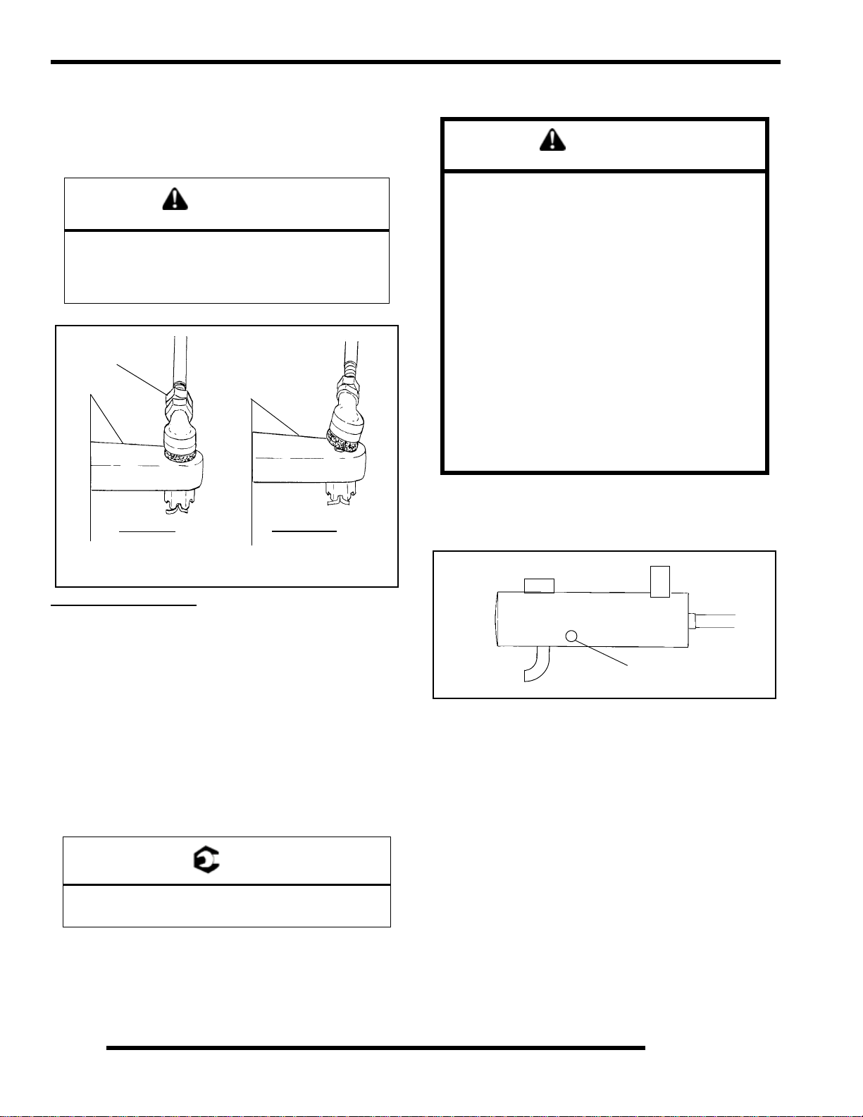
MAINTENANCE
Toe Alignment Adjustment
If toe alignment is incorrect, measure the distance between
vehicle center and each wheel. This will tell you which tie rod
needs adjusting. NOTE: Be sure handlebars are straight ahead
before determining which tie rod(s) need adjustment.
CAUTION
During tie rod adjustment, it is very important that the
following precautions be taken when tightening tie
rod end jam nuts. If the rod end is positioned
incorrectly it will not pivot, and may break
Hold
Rod End
Correctly
Tightened
Jam Nut
III. 2
Incorrectly
Tightened
Jam Nut
Exhaust Pipe
WARNING
• Do not perform clean out immediately after the
engine has been run, as the exhaust system
becomes very hot. Serious burns could result
from contact with exhaust components.
• To reduce fire hazard, make sure that there are no
combustible materials in the area when purging
the spark arrestor.
• Wear eye protection.
• Do not stand behind or in front of the vehicle
while purging the carbon from the spark arrestor.
• Never run the engine in an enclosed area.Exhaust
contains poisonous carbon monoxide gas.
• Do not go under the machine while it is
inclined.Set the hand brake and block the wheels
to prevent roll back.
Failure to heed these warnings could result in serious
personal injury or death.
The exhaust pipe must be periodically purged of accumulated
carbon as follows:
1. Remove the clean out plugs located on the bottom of the
muffler.
To adjust toe alignment:
• Hold tie rod end to keep it from rotating.
• Loosen jam nuts at both end of the tie rod.
• Shorten or lengthen the tie rod until alignment is as
required to achieve the proper toe setting as specified in
Method 1 or Method 2.
• IMPORTANT: When tightening the tie rod end jam
nuts, the rod ends must be held parallel to prevent rod
end damage and premature wear. Damage may not be
immediately apparent if done incorrectly. See
illustration 2.
• After alignment is complete, torque jam nuts to
specification.
= T
Tie Rod Jam Nut Torque:
12-14 ft. lbs. (16-19 Nm)
Clean Out Plug
III. 1
2. Place the transmission in Park and start the engine. Purge
accumulated carbon from the system by momentarily
revving the engine several times.
2.28
Page 49

MAINTENANCE
3. If some carbon is expelled, cover the exhaust outlet and
lightly tap on the pipe around the clean out plugs with a
rubber mallet while revving the engine several more times.
4. If particles are still suspected to be in the muffler, back the
machine onto an incline so the rear of the machine is one
foot higher than the front. Set the hand brake and block the
wheels. Make sure the machine is in Park and repeat Steps
2 and 3. SEE WARNING
5. If particles are still suspected to be in the muffler, drive the
machine onto the incline so the front of the machine is one
foot higher than the rear. Set the hand brake and block the
wheels. Make sure the machine is in Park and repeat Steps
2 and 3. SEE WARNING
Brake System Inspection
The following checks are recommended to keep the brake
system in good operating condition. Service life of brake system
components depends on operating conditions. Inspect brakes in
accordance with the maintenance schedule and before each ride.
• Keep fluid level in the master cylinder reservoir to the
indicated level inside reservoir.
• Use Polaris DOT 3 Brake Fluid
Sight Glass
Parking Lock Brake
• Use Polaris DOT 3 Brake Fluid
2
1 ft.
6. Repeat steps 2 through 5 until no more particles are
expelled when the engine is revved.
7. Stop the engine and allow the arrestor to cool.
8. Reinstall the clean out plugs.
• Check brake for excessive travel or spongy feel.
• Check brake system for fluid leaks.
• Check friction pads for wear, damage or looseness.
• Check surface condition of the disc.
2.29
Page 50

MAINTENANCE
Brake Pad Inspection
Pads should be changed when the friction material i s worn to
.180” / 4.6 mm, or about the thickness of a dime.
.180” / 4.6 mm,
Minimum
Thickness
= In. / mm.
Brake Pad Service Limit:
.180" (4.6 mm)
2. While turning the rear wheels by hand, apply the auxiliary
foot brake. This brake should not stop the wheels from
turning until the lever is half way between its rest position
and bottoming on the footrest.
Auxiliary Foot Brake Pedal
Full Height
Floor
Board Surface
Full
Engagement
Auxiliary Brake Adjustment (Hydraulic)
Use the following procedure to inspect the hydraulic auxiliary
(foot) brake system and adjust or bleed if necessary:
First, check foot brake effectiveness by applying 50 lb.
(approx.) downward force on the pedal. The top of the pedal
should be at least 1 inch, (25.4mm) above the surface of the
footrest.
Hose/Fitting Inspection
Check brake system hoses and fittings for cracks, deterioration,
abrasion, and leaks.Tighten any loose fittings and replace any
worn or damaged parts.
Auxiliary Brake Testing
The auxiliary brake should be checked for proper function.
Auxiliary Brake
1. Support the rear wheels off the ground.
1/8, to 1/4,
Free Play
If less than one inch, two things must be examined:
Free Play:
50 lbs
1” or
greater
Floorboard
= In. / mm.
Foot Brake Freeplay:
1/8 - 1/4 inch (3.2 - 6.35 mm)
If free play is excessive, inspect pedal, linkage, and master
cylinder for wear or damage and replace any parts as needed.
Bleeding:
If free play is correct and brake pedal travel is still excessive, air
may be trapped somewhere in the system. Bleed the hydraulic
auxiliary brake system in a conventional manner, following the
procedure outlined in Brake Chapter 9.
2.30
Page 51

MAINTENANCE
Suspension Spring Preload Adjustment
Center Spring
Adjustment Ring
1
2
Shock Spanner Wrench
(PN 2871095)
Operator weight and vehicle loading affect suspension spring
preload requirements. Adjust as necessary, using the spanner
wrench (2) to turn the adjustment cam (1).
Controls
2
Check controls for proper operation, positioning and
adjustment.
Brake control and switch must be positioned to allow brake
lever to travel throughout entire range without contacting switch
body.
Throttle
assembly
clamp
Front Suspension
Compress and release front suspension. Damping
should be smooth throughout the range of travel.
Check all front suspension components for wear or damage.
Inspect front strut cartridges for leakage.
CV Shaft Boot Inspection
Inspect the CV shaft boots in the front and rear of the ATV for
damage, tears, wear, or leaking grease. If the rubber boot
exhibits any of these symptoms, replace the boot. Refer to
Chapter 7 for CV boot replacement.
Inspect Boots
Align clamp
edge with
knurl
Align throttle control assembly clamp with knurl on handlebar.
Wheels
Inspect all wheels for runout or damage. Check wheel nuts and
ensure they are tight. Do not over tighten the wheel nuts.
WARNING
Operating an ATV with worn tires will increase the
possibility of the vehicle skidding and possible loss
of control.
Worn tires can cause an accident.
Always replace tires when the tread depth
measures 1/8” (.3 cm) or less.
Inspect all wheels for runout or damage. Check wheel nuts and
ensure they are tight. Do not over tighten the wheel nuts.
2.31
Page 52

MAINTENANCE
Wheel, Hub, And Spindle Torque Ta ble
Item Specification
Steel - Front Wheel Nuts 27 Ft. Lbs. (37 Nm)
Steel - Rear Wheel Nut s 27 Ft. Lbs. (37Nm)
Aluminum
Front Wheel Nuts
Aluminum
Rear Wheel Nuts
Front Hub Retaining Nut 70 ft.lbs. (90 Nm)
Rear Hub Retaining Nut 80 Ft. Lbs. (108 Nm)
90 Ft. Lbs. (122 Nm)
90 Ft. Lbs. (122 Nm)
Wheel Removal Front or Rear
Front & Rear Wheels
Front & Rear
Wheel Nuts (4)
See table Below
Wheel Installation
1. With the transmission in Park and the parking brake
locked, place the wheel in the correct position on the wheel
hub. Be sure the valve stem is toward the outside and
rotation arrows on the tire point toward forward rotation.
2. Attach the wheel nuts and finger tighten them.
3. Lower the vehicle to the ground.
4. Securely tighten the wheel nu ts to th e proper torqu e li sted
in the table.
Steel Wheel Aluminium Wheel
Front Hub Nut
70 ft. lbs. (95 Nm)
Rear Hub Nut
80 ft. lbs. (108 Nm)
1. Stop the engine, place the transmission in Park and lock
the parking brake.
2. Loosen the wheel nuts slightly.
• Elevate the side of the vehicle by placing a suitable
stand under the footrest frame.
CAUTION
If wheels are improperly installed it could affect
vehicle handling and tire wear. On vehicles with
tapered rear wheel nuts, make sure tapered end of
nut goes into taper on wheel.
Tire Pressure
CAUTION
Maintain proper tire pressure. Refer to the warning tire
pressure decal applied to the vehicle.
Tire Pressure Inspection (PSI - Cold)
Front Rear
55
3. Remove the wheel nuts and remove the wheel.
2.32
Page 53

MAINTENANCE
Tire Inspection
• Improper tire inflation may affect ATV
maneuverability.
• When replacing a tire always use original equipment
size and type.
• The use of non-standard size or type tires may affect
ATV handling.
Tire Tread Depth
Always replace tires when tread depth is worn to 1/8" (3 mm)
or less.
Tread
Depth 1/8” (3 mm)
Storage Compartments
The storage compartments are easily accessible. To open the
front compartment turn the latch handle to the horizontal
position on both sides. To close the storage compartment turn
the latch handles just past the vertical position. Use the arrow
located on top of the latch as a reference.
2
Unlatch
WARNING
Operating an ATV with worn tires will increase the
possibility of the vehicle skidding easily with
possible loss of control.
Worn tires can cause an accident.
Always replace tires when the tread depth
measures 1/8” (.3 cm) or less.
Frame, Nuts, Bolts, Fasteners
Periodically inspect the torque of all fasteners in accordance
with the maintenance schedule. Check that all cotter pins are in
place. Refer to specific fastener torques listed in each chapter.
Latch
2.33
Page 54

MAINTENANCE
Winch Operation (If Equipped)
This information is for Sportsman models equipped with a
winch in the front.
Winch Handlebar Control
The winch is located in the front bumper area.
s
The mini-rocker (IN/OUT) control controls the direction of the
cable for the winch. IN pulls the cable into the winch and OUT
feeds the cable out of the winch.
Winch Control
The winch control located on the side of the winch gives the
operator easy access to switch between ENGAGED and
FREESPOOL.
When the winch is ENGAGED, the winch only allows the cable
to be pulled IN or released OUT via the mini-rocker switch on
the handlebar.
When the winch is FREESPOOL, the winch allows the cable to
be pulled out freely.
NOTE: The switch on the handlebar does not have to be in
the OUT position.
L
FREESPOOL
ENGAGE
Winch Wire Locations
The winch wires can be located under the front cab area. Locate
the wires, remove the cap and hook up to winch the Blue an d
2.34
Page 55

MAINTENANCE
Yellow (6 Ga.) wires to the winch. Refer to the installation
instructions for more details.
Winch Connector
Splash Guard for Contactor mount
Winch Connecting
Harness
The Orange/White wires are located under the front cover
(under headlight pod). The Orange/White wires supply the
control power to the winch.
2
Right Side Front Fender
Locate the Red wire (6 Ga.) with the yellow crimp cover is
located in the rear fender area. The red wire connects to the
battery.
Winch Connecting Wire
2.35
Page 56

MAINTENANCE
ATV Cleaning & Storage
Cleaning the ATV
Keeping your ATV clean will not only improve its appearance
but it can also extend the life of various components. With a few
precautions, your A TV can be cleaned much like an automobile.
Washing the ATV
The best and safest way to clean your A TV is with a garden hose
and a pail of mild soap and water. Use a professional type
washing mitten, cleaning the upper body first and the lower parts
last. tRinse with water frequently and dry with a chamois to
prevent water spots. NOTE: If warning and safety labels are
damaged, contact your a Polaris dealer for free replacement.
Polaris does not recommend the use of a high pressure type car
wash system for washing the ATV. If a high pressure system is
used, exercise extreme care to avoid water damage to the wheel
bearings, transmission seals, body panels, brakes and warning
labels. NOTE: Grease all zerk fittings immediately after
washing, and allow the vehicle to run for a while to evaporate
any water that may have entered the engine or exhaust system.
Waxing the ATV
Your ATV can be waxed with any non-abrasive automotive
paste wax. A void the use of harsh cleaners since they can scratch
the body finish. Polaris offers a detailing kit for ATVs.
CAUTION
Certain products, including insect repellents and
chemicals, will damage plastic surfaces. Use caution
when using these products near plastic surfaces.
Storage Tips
See Page 2.9 for the part numbers of Polaris products .
CAUTION
Starting the engine during the storage period will
disturb the protective film created by fogging and
damage could occur. Never start the engine during
the storage period.
Clean the Exterior
Make necessary repairs and then clean the ATV thoroughly with
mild soap and warm water to remove all dirt and grime. Don’t
use harsh detergents or hig h pressure washers. Some deter gents
deteriorate rubber parts. Use dish soap type cleaners only . High
pressure washers may force water past seals.
Stabilize the Fuel
Fill the fuel tank. Add Polaris Carbon Clean Fuel Treatment or
Polaris Fuel Stabilizer . Follow the instructions on the container
for the recommended amount. (Carbon clean will also reduce
the possibility of bacterial growth in the fuel system). Allow 1520 minutes of operation for the stabilizer to disperse through the
fuel in the tank and EFI sytem / carburetor. Turn the fuel valve
off and drain the carburetor bowl (450 only).
Oil and Filter
Warm the engine and change the oil and filter. Follow the
procedure in this chapter for proper oil change.
Air Filter / Air Box
Inspect and clean or replace the pre-cleaner and air filter. Clean
the air box and drain the sediment tube.
Breather Filter
Inspect and clean or replace the breather filter.
Fluid Levels
Inspect the following fluid levels and change if necessary: front
gearcase; transmission; brake fluid (change every two years or
as required if fluid looks dark or contaminated).
Drain the Recoil Housing
Remove the recoil housing drain plug and drain any moisture.
Storage Kits
Polaris offers storage kits for ATVs. See a Polaris dealer or visit
www.purepolaris.com.
Fog the Engine
To properly store the engine, us e Polaris Fogging Oil according
to the directions.
If you choose not to use Polaris Fogging Oil, perform the
following procedure:
1. Support the front end of the machine so the engine is level
or tilted slightly rearward.
2. Treat the fuel system with Polaris Carbon Clean according
to the directions.
3. Remove the spark plug and add 2-3 tablespoons of
Premium 4 Synthetic 0W-40 engine oil. To access the plug
hole, use a section of clear 1/4” hose and a small plastic
squeeze bottle filled with the pre-measured amount of oil.
Note: Do this carefully! If you miss the plug hole, oil will
drain from the spark plug cavity into the hole at the front
of the cylinder head, and appear to be an oil leak. Install
the spark plug and pull the engine over slowly with the
recoil starter. Oil will be forced in and around the piston
rings and ring lands, coating the cylinder with a protective
film of fresh oil.
4. Apply dielectric grease to the inside of the spark plug cap
and install the cap onto the plug.
2.36
Page 57

MAINTENANCE
5. Turn the engine over sev eral ti mes with the recoil only to
ensure coverage of piston rings, cylinder walls and
crankshaft bearings.
6. If Polaris fuel system additive is not used, fuel tank, and fuel
lines should be completely drained of gasoline.
Lubricate
Inspect all cables and lubricate with Polaris Cable Lubricant.
Follow lubrication guidelines in the maintenance section of the
service or owner’s manual to completely grease and lubricate
the entire vehicle with Polaris Premium All Season Grease.
Storage Tips
Battery Storage
Remove the battery from the vehicle and ensure that it’s fully
charged before placing it in storage. See Chapter 10 for
instructions.
Engine Anti-Freeze
Test engine coolant strength and change if necessary. Coolant
should be replaced every two years.
Storage Ar ea/Covers
Set the tire pressure and safely support the A TV with the tires 12” off the ground. Be sure the storage area is well ventilated, and
cover the machine with a genuine Polaris ATV cover. NOTE:
Do not use plastic or coated materials. They do not allow enough
ventilation to prevent condensation, and may promote corrosion
and oxidation.
Transporting the ATV
Follow these procedures when transporting the vehicle.
1. Turn off the engine and rem ove the key to prevent loss
during transporting.
2. Always place the transmission in park and lock the parking
brake.
3. Turn the fuel valve off.
4. Be sure the fuel cap, oil cap and seat are installed correctly.
5. Always tie the frame of the ATV to the transporting unit
securely using suitable straps or rope.
2
2.37
Page 58

MAINTENANCE
Maintenance Schedule
Service Date Hours / Miles Service Performed Serviced By:
2.38
Page 59

ENGINE
CHAPTER 3
ENGINE
SPECIFICATIONS. . . . . . . . . . . . . . . . . . . . . . . . . . . . . . . . . . . . . . . . . . . . . . . . . . . . . . . 3.3
TORQUE SPECIFICATIONS . . . . . . . . . . . . . . . . . . . . . . . . . . . . . . . . . . . . . . . . . . . . . .3.3
SPECIAL TOOLS . . . . . . . . . . . . . . . . . . . . . . . . . . . . . . . . . . . . . . . . . . . . . . . . . . . . . . .3.3
ENGINE FASTENER TORQUE PATTERNS. . . . . . . . . . . . . . . . . . . . . . . . . . . . . . . . . .3.3
ENGINE SERVICE DATA. . . . . . . . . . . . . . . . . . . . . . . . . . . . . . . . . . . . . . . . . . . . . . . . .3.4
ENGINE SERVICE DATA. . . . . . . . . . . . . . . . . . . . . . . . . . . . . . . . . . . . . . . . . . . . . . . . .3.5
GENERAL ENGINE SERVICE . . . . . . . . . . . . . . . . . . . . . . . . . . . . . . . . . . . . . . . . . . . . . 3.6
PISTON IDENTIFICATION . . . . . . . . . . . . . . . . . . . . . . . . . . . . . . . . . . . . . . . . . . . . . . . .3.6
COOLING SYSTEM SPECIFICATIONS. . . . . . . . . . . . . . . . . . . . . . . . . . . . . . . . . . . . . .3.6
COOLING SYSTEM . . . . . . . . . . . . . . . . . . . . . . . . . . . . . . . . . . . . . . . . . . . . . . . . . . . . .3.7
ACCESSIBLE COMPONENTS. . . . . . . . . . . . . . . . . . . . . . . . . . . . . . . . . . . . . . . . . . . . .3.8
ENGINE REMOVAL (TYPICAL). . . . . . . . . . . . . . . . . . . . . . . . . . . . . . . . . . . . . . . . . . . .3.8
ENGINE INSTALLATION NOTES . . . . . . . . . . . . . . . . . . . . . . . . . . . . . . . . . . . . . . . . . .3.9
CYLINDER HONE SELECTION/ HONING PROCEDURE. . . . . . . . . . . . . . . . . . . . . . . .3.9
HONING TO OVERSIZE . . . . . . . . . . . . . . . . . . . . . . . . . . . . . . . . . . . . . . . . . . . . . . . . .3.9
CLEANING THE CYLINDER AFTER HONING . . . . . . . . . . . . . . . . . . . . . . . . . . . . . . .3.10
CRANKSHAFT STRAIGHTENING. . . . . . . . . . . . . . . . . . . . . . . . . . . . . . . . . . . . . . . . .3.10
ENGINE LUBRICATION - EH 50PL. . . . . . . . . . . . . . . . . . . . . . . . . . . . . . . . . . . . . . . .3.11
OIL PRESSURE TEST - EH 50PL . . . . . . . . . . . . . . . . . . . . . . . . . . . . . . . . . . . . . . . . .3.11
OIL PUMP PRIMING PROCEDURE . . . . . . . . . . . . . . . . . . . . . . . . . . . . . . . . . . . . . . .3.11
OIL FLOW - EH50PL . . . . . . . . . . . . . . . . . . . . . . . . . . . . . . . . . . . . . . . . . . . . . . . . . . .3.11
EH50PL OIL FLOW DIAGRAM. . . . . . . . . . . . . . . . . . . . . . . . . . . . . . . . . . . . . . . . . . . .3.12
EH50PL ENGINE EXPLODED VIEWS. . . . . . . . . . . . . . . . . . . . . . . . . . . . . . . . . . . . . .3.13
ENGINE DISASSEMBLY. . . . . . . . . . . . . . . . . . . . . . . . . . . . . . . . . . . . . . . . . . . . . . . . . 3.14
CAM CHAIN TENSIONER/ROCKER ARM/ CAMSHAFT REMOVAL . . . . . . . . . . . . . .3.14
CAM CHAIN TENSIONER INSPECTION. . . . . . . . . . . . . . . . . . . . . . . . . . . . . . . . . . . .3.14
ROCKER ARM/SHAFT INSPECTION . . . . . . . . . . . . . . . . . . . . . . . . . . . . . . . . . . . . . .3.15
CAMSHAFT REMOVAL . . . . . . . . . . . . . . . . . . . . . . . . . . . . . . . . . . . . . . . . . . . . . . . . .3.16
AUTOMATIC COMPRESSION RELEASE REMOVAL/INSPECTION . . . . . . . . . . . . . .3.17
AUTOMATIC COMPRESSION RELEASE INSTALLATION. . . . . . . . . . . . . . . . . . . . . .3.18
CAMSHAFT INSPECTION. . . . . . . . . . . . . . . . . . . . . . . . . . . . . . . . . . . . . . . . . . . . . . .3.18
CYLINDER HEAD REMOVAL . . . . . . . . . . . . . . . . . . . . . . . . . . . . . . . . . . . . . . . . . . . .3.19
CYLINDER HEAD EXPLODED VIEW, EH50PL. . . . . . . . . . . . . . . . . . . . . . . . . . . . . . .3.20
CYLINDER HEAD INSPECTION . . . . . . . . . . . . . . . . . . . . . . . . . . . . . . . . . . . . . . . . . .3.21
CYLINDER HEAD WARP. . . . . . . . . . . . . . . . . . . . . . . . . . . . . . . . . . . . . . . . . . . . . . . .3.21
CYLINDER HEAD DISASSEMBLY . . . . . . . . . . . . . . . . . . . . . . . . . . . . . . . . . . . . . . . .3.21
VALVE INSPECTION. . . . . . . . . . . . . . . . . . . . . . . . . . . . . . . . . . . . . . . . . . . . . . . . . . .3.22
COMBUSTION CHAMBER. . . . . . . . . . . . . . . . . . . . . . . . . . . . . . . . . . . . . . . . . . . . . . .3.23
VALVE SEAT RECONDITIONING . . . . . . . . . . . . . . . . . . . . . . . . . . . . . . . . . . . . . . . . .3.23
CYLINDER HEAD ASSEMBLY . . . . . . . . . . . . . . . . . . . . . . . . . . . . . . . . . . . . . . . . . . .3.26
VALVE SEALING TEST . . . . . . . . . . . . . . . . . . . . . . . . . . . . . . . . . . . . . . . . . . . . . . . . .3.26
VALVE CLEARANCE ADJUSTMENT . . . . . . . . . . . . . . . . . . . . . . . . . . . . . . . . . . . . . .3.26
CYLINDER/PISTON REMOVAL AND INSPECTION. . . . . . . . . . . . . . . . . . . . . . . . . . .3.27
PISTON REMOVAL . . . . . . . . . . . . . . . . . . . . . . . . . . . . . . . . . . . . . . . . . . . . . . . . . . . .3.28
CYLINDER INSPECTION. . . . . . . . . . . . . . . . . . . . . . . . . . . . . . . . . . . . . . . . . . . . . . . .3.28
PISTON-TO-CYLINDER CLEARANCE . . . . . . . . . . . . . . . . . . . . . . . . . . . . . . . . . . . . .3.29
PISTON/ROD INSPECTION. . . . . . . . . . . . . . . . . . . . . . . . . . . . . . . . . . . . . . . . . . . . . .3.29
PISTON RING INSTALLED GAP. . . . . . . . . . . . . . . . . . . . . . . . . . . . . . . . . . . . . . . . . .3.30
CRANKCASE DISASSEMBLY. . . . . . . . . . . . . . . . . . . . . . . . . . . . . . . . . . . . . . . . . . . .3.30
STARTER DRIVE REMOVAL/INSPECTION . . . . . . . . . . . . . . . . . . . . . . . . . . . . . . . . .3.31
FLYWHEEL/STATOR REMOVAL/INSPECTION. . . . . . . . . . . . . . . . . . . . . . . . . . . . . .3.31
CAM CHAIN/TENSIONER BLADE. . . . . . . . . . . . . . . . . . . . . . . . . . . . . . . . . . . . . . . . .3.32
ONE WAY VALVE REMOVAL . . . . . . . . . . . . . . . . . . . . . . . . . . . . . . . . . . . . . . . . . . . .3.32
CRANKCASE SEPARATION . . . . . . . . . . . . . . . . . . . . . . . . . . . . . . . . . . . . . . . . . . . . .3.33
3
3.1
Page 60

ENGINE
OIL PUMP REMOVAL/INSPECTION. . . . . . . . . . . . . . . . . . . . . . . . . . . . . . . . . . . . . . .3.33
OIL PUMP ASSEMBLY . . . . . . . . . . . . . . . . . . . . . . . . . . . . . . . . . . . . . . . . . . . . . . . . . 3.34
COUNTER BALANCER SHAFT REMOVAL/INSPECTION. . . . . . . . . . . . . . . . . . . . . . 3.34
CRANKSHAFT REMOVAL/INSPECTION . . . . . . . . . . . . . . . . . . . . . . . . . . . . . . . . . . . 3.35
CRANKCASE BEARING INSPECTION. . . . . . . . . . . . . . . . . . . . . . . . . . . . . . . . . . . . .3.36
PUMP SHAFT OIL SEAL/WATER PUMP MECHANICAL SEAL REMOVAL . . . . . . . . 3.36
CRANKCASE INSPECTION . . . . . . . . . . . . . . . . . . . . . . . . . . . . . . . . . . . . . . . . . . . . . 3.36
BEARING INSTALLATION. . . . . . . . . . . . . . . . . . . . . . . . . . . . . . . . . . . . . . . . . . . . . . .3.37
END PLAY INSPECTION/ADJUSTMENT . . . . . . . . . . . . . . . . . . . . . . . . . . . . . . . . . . . 3.37
CRANKSHAFT END PLAY ADJUSTMENT . . . . . . . . . . . . . . . . . . . . . . . . . . . . . . . . . . 3.37
COUNTER BALANCER SHAFT END PLAY ADJUSTMENT. . . . . . . . . . . . . . . . . . . . . 3.38
OIL PUMP SHAFT END PLAY ADJUSTMENT . . . . . . . . . . . . . . . . . . . . . . . . . . . . . . . 3.39
ENGINE REASSEMBLY . . . . . . . . . . . . . . . . . . . . . . . . . . . . . . . . . . . . . . . . . . . . . . . . . 3.40
PUMP SHAFT OIL SEAL INSTALLATION. . . . . . . . . . . . . . . . . . . . . . . . . . . . . . . . . . . 3.40
CRANKSHAFT/COUNTER BALANCE/OIL PUMP INSTALLATION . . . . . . . . . . . . . . . 3.40
CRANKCASE ASSEMBLY. . . . . . . . . . . . . . . . . . . . . . . . . . . . . . . . . . . . . . . . . . . . . . .3.41
WATER PUMP MECHANICAL SEAL INSTALLATION . . . . . . . . . . . . . . . . . . . . . . . . . 3.41
WATER PUMP MECHANICAL SEAL REMOVAL - ENGINE INSTALLED . . . . . . . . . .3.41
ONE WAY VALVE INSTALLATION . . . . . . . . . . . . . . . . . . . . . . . . . . . . . . . . . . . . . . . . 3.42
CAM CHAIN DRIVE SPROCKET INSTALLATION . . . . . . . . . . . . . . . . . . . . . . . . . . . .3.43
TENSIONER BLADE INSTALLATION. . . . . . . . . . . . . . . . . . . . . . . . . . . . . . . . . . . . . .3.43
PISTON RING INSTALLATION . . . . . . . . . . . . . . . . . . . . . . . . . . . . . . . . . . . . . . . . . . . 3.43
PISTON INSTALLATION . . . . . . . . . . . . . . . . . . . . . . . . . . . . . . . . . . . . . . . . . . . . . . . . 3.44
CYLINDER INSTALLATION. . . . . . . . . . . . . . . . . . . . . . . . . . . . . . . . . . . . . . . . . . . . . . 3.44
CYLINDER HEAD INSTALLATION . . . . . . . . . . . . . . . . . . . . . . . . . . . . . . . . . . . . . . . .3.45
CAM CHAIN/CAMSHAFT INSTALLATION . . . . . . . . . . . . . . . . . . . . . . . . . . . . . . . . . .3.45
CAMSHAFT TIMING . . . . . . . . . . . . . . . . . . . . . . . . . . . . . . . . . . . . . . . . . . . . . . . . . . . 3.46
CAMSHAFT TIMING . . . . . . . . . . . . . . . . . . . . . . . . . . . . . . . . . . . . . . . . . . . . . . . . . . . 3.48
CAM CHAIN TENSIONER INSTALLATION. . . . . . . . . . . . . . . . . . . . . . . . . . . . . . . . . .3.49
STATOR, FLYWHEEL AND STARTER DRIVE INSTALLATION. . . . . . . . . . . . . . . . . .3.49
ROCKER SHAFT/ROCKER ARM ASSEMBLY INSTALLATION. . . . . . . . . . . . . . . . . . 3.50
THERMOSTAT INSTALLATION . . . . . . . . . . . . . . . . . . . . . . . . . . . . . . . . . . . . . . . . . .3.50
OIL PIPES . . . . . . . . . . . . . . . . . . . . . . . . . . . . . . . . . . . . . . . . . . . . . . . . . . . . . . . . . . .3.50
RECOIL . . . . . . . . . . . . . . . . . . . . . . . . . . . . . . . . . . . . . . . . . . . . . . . . . . . . . . . . . . . . . . 3.51
RECOIL DISASSEMBLY/INSPECTION. . . . . . . . . . . . . . . . . . . . . . . . . . . . . . . . . . . . .3.51
RECOIL ASSEMBLY . . . . . . . . . . . . . . . . . . . . . . . . . . . . . . . . . . . . . . . . . . . . . . . . . . .3.52
TROUBLESHOOTING. . . . . . . . . . . . . . . . . . . . . . . . . . . . . . . . . . . . . . . . . . . . . . . . . . . 3.53
SPARK PLUG FOULING . . . . . . . . . . . . . . . . . . . . . . . . . . . . . . . . . . . . . . . . . . . . . . . .3.53
ENGINE . . . . . . . . . . . . . . . . . . . . . . . . . . . . . . . . . . . . . . . . . . . . . . . . . . . . . . . . . . . . .3.53
COOLING SYSTEM . . . . . . . . . . . . . . . . . . . . . . . . . . . . . . . . . . . . . . . . . . . . . . . . . . . .3.54
3.2
Page 61

ENGINE
SPECIFICATIONS
Torque Specifications
TORQUE SPECIFICATIONS
Fastener Size EH50PLE
Ft. Lbs. (Nm)
Blind Plug (Oil
Pressure)
Camshaft S procket 6mm 5-6.5 (7-9 Nm)
Camshaft Chain
Tensioner Lever
Camshaft Chain
Tensioner
Camshaft Chain
Tensioner Cap
Carburetor Adaptor 8mm 12-14 (16-20 Nm)
Crankcase 8mm 14-15 (19-21 Nm)
Crankshaft Slotted Nut
(Cam Chain Drive
Sprocket)
Cylinder Base Bolts 10mm
Cylinder Head Bolts 11mm
Drive Clutch Bolt 7/16 - 20 40 (55 Nm)
Flywheel 16mm 58-72 (78-98 Nm)
Oil Delivery Pipe 12mm 11-15 (15-21 Nm)
Oil Drain Bolt
(Crankcase)
Oil Filter Pipe Fitting 20mm 36-43 (49-59 Nm)
Oil Hose Fitting 1/8 Pipe
Hard Metal Oil Line
Banjo Fitting
Oil Pump 6mm 5-6.5 (7-9 Nm)
Oil Pump Case Screw 5mm 1.5-2 (2-3 Nm)
One Way Valve 11mm 14-19 (20-25 Nm)
Recoil Housing 6mm 5-6.5 (7-9 Nm)
Rocker Cover 6mm 7-8 (9-11 Nm)
Rocker Support 8mm 8-10 (11-13 Nm)
Rocker Adjuster Screw 6mm 6-7 (8-10 Nm)
Water Pump Impeller
Nut
Water Pump Housing
Cover
Stator Plate 6mm 5- 6.5 (7-9 Nm)
Starter Motor 6mm 5-6.5 (7-9 Nm)
Spark Plug 14mm 9-11 (12-15 Nm)
Thermistor -- 26 ± 2.1 (35 ± 3 Nm)
1/8 PT
(28tpi)
6mm 5-6.5 (7-9 Nm)
6mm 5-6.5 (7-9 Nm)
11mm 14-19 (20-25 Nm)
28mm 35-51 (47- 69 Nm)
6mm
6mm
14mm 14-17 (19- 23 Nm)
Thread
N/A 11-16 ft.lbs. (15-21
6mm 5-6.5 (7-9 Nm)
6mm 5-6.5 (7-9 Nm)
6.5-11 (9-15 Nm)
45-49 (61-67 Nm)
6-8 (9-11 Nm)
Refer to Engine
Assembly for torque
procedure
6.5-11 (9-15 Nm)
Nm)
Special Tools
PART NUMBER TOOL DESCRIPTION
2200634
2870390 Piston Support Block
2871043 Flywheel Puller
2871283
5131135 Water Pump Install Kit
2870569 Crankshaft Truing Stand
2870975
PV-43527 OIl Filter Wrench
Valve Seat Reconditioning
Kit
Crankshaft/Water Pump
Seal Install Kit
Mity Vac™ Pressure Test
Tool
Engine Fastener Torque Patterns
Tighten cylinder head, cylinder base, and crankcase fasteners in
3 steps following the sequence outlined.
6mm
3
1
Cylinder Head
Cylinder Base
Pattern
7
3
2
4
2
4
5
1
Crankcase
Pattern
5
6
9
10
8
6
3
3.3
Page 62

ENGINE
Engine Service Data
Cylinder Head / Valve
Rocker Arm Rocker arm ID .8669-.8678" (22.020-22.041 mm)
Rocker shaft OD .86 56-.8661" (21.987-22.0 mm)
Rocker shaft Oil Clearance Std .0008-.0021" (.020-.054 mm)
Limit .0039" (.10 mm)
Camshaft Cam lobe height In Std 1.2884-1.2924” (32.726-32.826 mm)
Limit 1.2766" (32.426 mm)
Ex Std 1.2884-1.2924” (32.726-32.826 mm)
Limit 1.2766" (32.426 mm)
Camshaft journal OD Mag 1.4935-1.4941” (37.935-37.950 mm)
PTO 1.4935-1.4941” (37.935-37.950 mm)
Camshaft journal bore ID Mag 1.4 963-1.4970” (38.005-38.025 mm)
PTO 1.4963-1.4970” (38.005-38.025 mm)
Camshaft Oil clearance Std .022-.0035”(.055-.090 mm)
Limit .0039" (.10 mm)
Cylinder Head Surface warpage limit .0020" (.05 mm)
Standard Height 3.870" (98.3 mm)
Valve Seat Contacting width In Std .028" (.7 mm)
Limit .055" (1.4 mm)
Ex Std .039" (1.0 mm)
Limit .071" (1.8 mm)
Valve Guide Inner diameter .2362-.2367" (6.0-6.012 mm)
Protrusion above head .689-.709" (17.5-18.0 mm)
Valve Margin Thickness In Std .039" (1.0 mm)
Limit .031" (.8 mm)
Ex Std .047" (1.2 mm)
Limit .031" (.8 mm)
Valve Stem diameter In .2343-.2348" (5.950-5.965 mm)
Ex .2341-.2346" (5.945-5.960 mm)
Stem Oil Clearance Std In .0014-.0024" (.035-.062 mm)
Ex .0016-.0026" (.040-.067 mm)
Limit .0059" (.15 mm)
Overall length In 3.976" (101.0 mm)
Ex 3.984" (101.2 mm)
Valve Spring Overall Length Std 1.654" (42.0 mm)
Limit 1.575" (40.0 mm)
Squareness .075” (1.9 mm)
EH50PLE
3.4
Page 63

Engine Service Data
Cylinder / Piston / Connecting Rod EH50PLE
Cylinder Surface warpage limit (mating with cylinder
head)
Cylinder bore Std 3.6221-3.6228” (92.00-92.02 mm)
Tap er limit .0020” (0.05 mm)
Out of round limit .0020” (0.05 mm)
Piston clearance Std .0006-.0018" (0.015-0.045 mm)
Boring Limit .020” (.5 mm)
Piston Outer diameter Std 3.6204-3.6215” (91.970-91.985mm)
Standard inner diameter of piston pin bore .9055-.9057” (23.0-23.006 mm)
Piston Pin Outer diameter .9053-.9055” (22.994-23.0 mm)
Standard clearance-piston pin to pin bore .0002-.0003” (.004-.008 mm)
Degree of fit
Piston Ring Piston Ring Installed
gap
.0020” (0.05 mm)
Limit .0024” (0.060 mm)
.0098" (.25 mm) OS 3.6304-3.6310” (92.21-92.23 mm)
.0197" (.50 mm) OS 3.6403-3.6407” (92.46-92.47 mm)
Piston Pin must be a push (by hand) fit at 68
Top ring Std .0079-.0138" (.20-.36 mm)
Limit .039” (1.0 mm)
ENGINE
o
F (20o
3
Second
ring
Oil ring Std .0079-.0276" (0.20-0.70 mm)
Piston Ring Standard clearance -
piston ring to ring
groove
Connecting
Rod
Crankshaft Crankshaft runout limit .0024” (.06 mm)
Connecting rod small end ID .9058- .9063” (23.007 - 23.020 mm)
Connecting rod small end radial
clearance
Connecting rod big end side
clearance
Connecting rod big end radial
clearance
Top ring Std .0016-.0031" (0.040.-080 mm)
Second
ring
Std .0079-.0138" (.20-.36 mm)
Limit .039” (1.0 mm)
Limit .059" (1.5 mm)
Limit .0059" (.15 mm)
Std .0012-.0028" (0.030-0.070 mm)
Limit .0059" (.15 mm)
Std .0003-.0010” (.007-.026 mm)
Limit .0020 (.05 mm)
Std .0039-.0256” (.1-.65 mm)
Limit .0315” (.80 mm)
Std .0004-.0015” (.011-.038 mm)
Limit .0020” (.05 mm)
KEY - Std: Standard; OS: Oversize; ID: Inner Diameter; OD: Outer Diameter; Mag: Magneto Side;
PTO: Power Take Off.
3.5
Page 64

ENGINE
GENERAL ENGINE SERVICE
Piston Identification
The piston may have an identification mark or the piston may
not have an identification mark for piston placement. If the
piston has an identification mark, follow the directions for
piston placement below. If the piston does not have an
identification mark, the direction for placement of the piston
does not matter.
Note the directional and identification marks when viewing the
pistons from the top. The letter “F”, “
be toward the flywheel side of the engine. The other numbers are
used for identification as to diameter, length and design. Four
stroke engine rings are rectangular profile. See text for oil
control ring upper rail installation. Use the information below to
identify pistons and rings.
Engine
Model No.
EH50PLE .25
EH42PLE .25
*Pistons and rings marked 25 equal .25mm (.010”) oversized
*Pistons and rings marked 50 equal .50mm (.020”) oversized
Oversize
Available* (mm)
.50
.50
J ”,“ X” or : must always
Piston
Length
72 mm C
66 mm B
Standard
Piston
Identification
Cooling System Specifications
Sensor
18.5 +
ft. lbs.
(25 Nm)
THERMISTOR READING DURING OPERATION
Condition
Temperature 37.3 - 39.2 k Ω 68° F (20° C)
System
Capacity
Radiator Cap
Relief
Pressure
Approx. Reading
(Min-Max)
2.25 Quarts
(2.13L)
13 PSI (89.6 kpa)
Temperature
3.6
Page 65

ENGINE
Cooling System
WARNING
Never remove radiator cap when engine is warm or hot.
The cooling system is under pressure and serious burns
may result. Allow the engine and cooling system to cool
before servicing.
FLOW
Radiator
Thermostat
Cylinder
Head
Water Pump
Cylinder
System Pressure Test
1. Remove radiator cap cover located in storage box.
2. Remove recovery bottle hose from coolant filler.
3. Connect a Mity Vac™ (PN 2870975) to radiator and
pressurize system to 10 PSI (68.9 kpa). The system must
retain 10 lbs of pressure for five minutes or longer. If
pressure loss is evident within five minutes, check radiator,
all cooling system hoses and clamps, or water pump seal.
Radiator Cap Pressure Test
1. Remove radiator cap and test using a cap tester
(commercially available).
2. The radiator cap relief pressure is 13 lbs (89.6 kpa).
3
Fan
Lower Hose
Overflow Bottle
Upper Hose
Filler Neck
Radiator
To p
Bottom
Radiator
Left Side
View
Radiator
Front
View
3.7
Page 66

ENGINE
RECOMMENDED COOLANT
Use only high quality antifreeze/coolant mixed with distilled
water in a 50/50 or 60/40 ratio, depending on freeze protection
required in your area..
CAUTION
Using tap water in the cooling system will lead to a
buildup of deposits which may restr ict co olant flow
and reduce heat dissipation, resulting in possible
engine damage. Polaris Premium 60/40 Antifree ze/
Coolant is recommended for use in all cooling
systems, and comes pre-mixed, ready to use.
Accessible Components
The following components can be serviced or removed with the
engine installed in the frame:
• Flywheel
• Alternator/Stator
• Starter Motor/Starter Drive
• Cylinder Head
• Cylinder
• Piston/RIngs
• Camshaft
• Rocker Arms
• Cam Chain and Sprockets
• Water Pump / Water Pump Mechanical Seal*
The following components require engine removal for
service:
Engine Removal (TYPICAL)
1. Clean work area.
2. Thoroughly clean the ATV engine and chassis.
3. Disconnect battery negative(-) cable.
4. Remove the following parts as required.
•Seat
• Left and Right Side Covers (Refer to Chapter 5)
• Fuel Tank Cover / Front Cab (Refer to Chapter 5)
• Fuel Tank (Refer to Chapter 4)
5. Disconnect spark plug high tension lead.
6. Remove springs from exhaust pipe and remove pipe.
7. Drain coolant and engine oil.
8. Remove air pre-cleaner and duct.
9. Remove airbox.
10. Remove carburetor. Insert a shop towel into the carburetor
flange to prevent dirt from entering the intake port.
11. Remove center chain guard on chain drive AWD models.
12. Remove center drive and driven sprocket bolts and remove
chain and sprockets as an assembly.
13. R efer to PVT System to remove outer clutch cover, drive
belt, drive clutch, driven clutch, and inner cover.
14. Starter motor. Note ground cable location. Mark positive
(+) cable mounting angle and remove cable.
15. Remove transmission linkage rod(s) from gear selector and
secure out of the way.
16. Disconnect coolant temperature sensor wire.
17. Remove engine to chassis ground cable.
18. Remove all engine mount nuts and / or engine mount plates.
19. Remove engine through right side of frame.
• Oil pump / Oil Pump Drive Gear
• Counterbalance Shaft or Bearing(s)
• Connecting Rod
• Crankshaft
• Crankshaft Main Bearings
• Crankcase
*It may be necessary to loosen engine mounts and move
engine slightly to access water pump. Use the Water
Pump Mechanical Seal Puller (PN 2872105) to replace
mechanical seal with engine in frame.
3.8
Page 67

ENGINE
Engine Installation Notes
After the engine is installed in the frame, review this checklist
and perform all steps that apply.
General Items
1. Install previously removed components using new gaskets,
seals, and fasteners where applicable.
2. Perform regular checks on fluid levels, controls, and all
important areas on the vehicle as outlined in the daily preride inspection checklist (refer to Chapter 2 or the Owner’s
Safety and Maintenance Manual).
PVT System
1. Adjust center distance of drive and driven clutch. (Chapter
6)
2. Adjust clutch offset, alignment, and belt deflection.
(Chapter 6)
3. Clean clutch sheaves thoroughly and inspect inlet and
outlet ducts for proper routing and sealing. (Chapter 6)
Transmission
1. Inspect transmission operation and adjust linkage if
necessary. Refer to Chapter 2 and Chapter 8.
Exhaust
1. Replace exhaust gaskets. Seal connections with high temp
silicone sealant if required.
2. Check to be sure all springs are in good cond ition.
Cylinder Hone Selection/ Honing Procedure
CAUTION
Selecting a hone which will straighten as well as
remove material from the cylinder is very important.
Using a common spring loaded finger type glaze
breaker for honing is never advised. Polaris
recommends using a rigid hone or arbor honing
machine which also has the capability of oversizing.
3
Cylinders may be wet or dry honed depending upon the
hone manufacturer’s recommendations. Wet honing
removes more material faster and leaves a more distinct
pattern in the bore.
NOTE: See next page for more information on honing.
Honing To Oversize
CAUTION
If cylinder wear or damage is excessive, it will be
necessary to oversize the cylinder using a new oversize
piston and rings. This may be accomplished by either
boring the cylinder and then finish honing to the final bore
size, or by rough honing followed by finish honing.
Bleed Cooling System
1. Remove radiator cap and slowly add coolant to top of filler
neck.
2. Fill coolant reservoir tank to ful l mark.
3. Install radiator cap and squeeze coolant lines to force air out
of system.
4. Again remove radi ator cap and slowly add coolant to top
of fill neck.
5. Start engine and observe coolant level in the radiator. Allow
air to purge and top off as necessary. Reinstall radiator cap
and bring engine to operating temp. Check level in reservoir
tank after engine is cool and add coolant if necessary.
Engine Break In Period
4 Cycle Engine Break-In Period is defined as the first 10
hours of engine operation or 2 full tanks of fuel.
1. Use only Polaris Premium 4 Al l Season synthetic oil, or
API certified “SH” oil.Never substitute or mix oil brands.
Serious engine damage can result.
2. Use fuel with a minimum octane of 87 (R+M)/2 met hod.
3. Change break-in oil and filter at 20 hours or 500 miles,
whichever comes first.
CAUTION
For oversize honing, always wet hone using honing oil
and a coarse roughing stone. Measure the piston (see
piston measurement) and rough hone to the size of the
piston. Always leave .002 - .003" (.05 - .07 mm) for finish
honing. Refer to piston-to-cylinder clearance
specifications before honing. Complete the sizing with
fine grit stones to provide the proper cross-hatch finish
and required piston clearance.
EXAMPLE OF CROSS HATCH PATTERN
3.9
Page 68

ENGINE
)
A finished cylinder should have a cross-hatch pattern to ensure
piston ring seating and to aid in the retention of the fuel/oil
mixture during initial break in. Hone cylinder according to hone
manufacturer’s instructions, or these guidelines:
• Use a motor speed of approximately 300-500
RPM, run the hone in and out of the cylinder
rapidly until cutting tension decreases. Remember
to keep the hone drive shaft centered (or cylinder
centered on arbor) and to bring the stones
approximately 1/2” (1.3 cm) above and below the
bore at the end of each stroke.
• Release the hone at regular intervals and inspect
the bore to determine if it has been cleared, and to
check piston fit. NOTE: Do not allow cylinder to
heat up during honing. The thinner areas of the
liner around the ports will expand causing uneven
bore.
• After honing has been completed inspect all port
opening areas for rough or sh arp edges. Apply a
slight chamfer to all ports to remove shar p edges
or burrs, paying particular attention to the corners
of the intake and exhaust ports.
Cleaning the Cylinder After Honing
It is very important that the cylinder be thoroughly cleaned after
honing to remove all grit material. Wash the cylinder in a
solvent, then in hot, soapy water. Pay close attention to areas
where the cylinder sleeve meets the aluminum casting (transfer
port area). Use electrical contact cleaner if necessary to clean
these areas. Rinse thoroughly, dry with compressed air, and oil
the bore immediately with Polaris 2 Cycle Lubricant.
Crankshaft Straightening
Lubricate the bearings and clamp the crankshaft securely in the
Crankshaft Truing Stand (PN 2870569). Refer to the
illustrations below.
Crankshaft Truing Stand
(PN 2870569)
NOTE: The rod pin position in relation to the dial
indicator position tells you what action is required to
straighten the shaft.
HIGH .004 (.1 mm)
HIGH .004 (.1 mm)
A
B
SUPPORT CRANKSHAFT
1. To correct a situation like the one shown in the illustration,
strike the shaft at point A with a brass hammer.
HERE
HIGH .002 (.05 mm)
HIGH .005 (.13 mm
A
2. To correct a situation like the one shown in the illustration,
squeeze the crankshaft at points A. (Use tool from
alignment kit).
HIGH .002 (.05 mm)
A
A
A
HIGH .005 (.13 mm)
3.10
Page 69

ENGINE
3. If the crank rod pin location is 180o from the dial indicator
(opposite that shown above), it will be necessary to spread
the crankshaft at position A as shown in the illustration at
right. When rebuilding and straightening a crankshaft,
runout must be as close to zero as possible.
NOTE: Maximum allowable runout is .0024”.
Engine LubricationEH 50PL
Oil Type:Polaris Premium 4 Synthetic
(PN 2871281); or API certified “SH” 0-40W oil
Capacity:. . . . . . . .Approximately 2 U.S. Quarts (1.9 l)
Filter Wrench . . . .(PV-43527)
*Drain Plug / Screen Fitting...14 ft. lbs. (19 Nm) (If fitting is
removed, follow oil pump priming procedure).
*Oil Pressure Specification...20 PSI @ 5500 RPM, Polaris
0W-40 Synthetic (Engine Hot)
Oil Pressure Test - EH 50PL
1. Remove blind plug on front left cyl ind er head.
2. Insert a 1/8 NPT oil pressure gauge adaptor into the cylinder
head and attach the gauge.
3. Start engine and allow it to reach operating temperature,
monitoring gauge indicator.
NOTE: Use only Polaris Premium 4 Synthetic Engine
Lubricant (PN 2871281).
Oil Pressure at 5500 RPM (Engine Hot):
Standard: 20 PSI
Minimum: 12 PSI
Oil Pump Priming Procedure
See “Oil Pump Priming Procedure” on page 2.25.
Oil Flow - EH50PL
The following chart describes the flow of oil through the
EH50PL engine. Beginning at the oil tank, the oil flows through
a screen fitting in the bottom of the tank and into the oil supply
hose. The feed side of the oil pump draws oil through the hose
and into the crankcase oil gallery, and then pumps the oil
through another passage to the one way valve. (When the engine
is off, the one way valve closes to prevent oil in the tank from
draining into the crankcase.) The oil is pumped through a
delivery pipe to the oil filter. If the oil filter is obstructed, a
bypass valve contained in the filter allows oil to bypass the filter
element.
At this point, the oil is diverted in two directions. Oil is supplied
to the camshaft through the left front cylinder stud, and an oil
passage in the head. Oil enters the camshaft through the PTO (L)
journal. The camshaft journals, cam lobes, and rocker arms are
lubricated through holes in the camshaft. The oil lubricates the
cam chain and sprocket and drains to the sump.
The other oil path from the filter leads through a del ivery pipe
to the crankcase main oil gallery, which leads to the stator plate
oil passage. Here it passes through the slotted friction bearing
(located in the stator plate) into the crankshaft. An oil seal on the
stator plate prevents oil from entering the stator/flywheel area.
Oil travels through the crankshaft to the crank pin, lubricating
the connecting rod large end bearing directly. Oil also passes
through an oil jet (drilled orifice) in the end of the crank pin to
the PTO end main bearings and counterbalancer gears.
Residual oil from the lubrication of the crankshaft and
connecting rod indirectly lubricates the cylinder wall, piston,
rings, connecting rod small end bearing, piston pin, oil/water
pump drive gears, cam chain and drive sprocket, and Magneto
end crankshaft main bearing.
The one-way valve is located on the front left (PTO) side of the
crankcase. The valve prevents oil in the tank from draining into
the engine sump when the engine is off. The valve mechanism
consists of a plunger, return spring, guide plug, and sealing
washer. When the engine is running, oil pressure lifts the
plunger off the seat, allowing oil flow. When the engine is off,
spring pressure forces the plunger against the oil passage seat,
preventing oil flow from the tank to the sump. The one-way
valve requires very little maintenance. If engine oil drains into
the sump when the engine is off, inspect the valve sealing
surface for debris or damage. Inspect the return spring for
distortion or damage.
3
3.11
Page 70

ENGINE
EH50PL Oil Flow Diagram
Internal passage to
camshaft (front left
head bolt)
Vent Hose
Oil Filter
Oil feed to filter
From filter to
crankshaft
Oil Tank
EH50PL Oil Flow Chart
Oil Tank
Union Fitting
(Upper)
Oil Hose
Crankcase
Oil Gallery
Oil Pump
Prevents oil from
draining into
crankcase with
engine off
(Feed)
One Way Valve
Top of Oil Tank
Oil Hose
Screen Fitting
(Bottom of Tank)
Cam Shaft
Journal
Bottom fitting is oil
exhaust or return
to tank
Union Fitting (Lower)
Crankcase
Oil Gallery
Chain Room
Rocker Arm
Rocker Shaft
Cam Lobe
One way valve
Top fitting is oil
feed or intake
from bottom of tank
Oil Pump
(Scavenging)
Sprocket
Chain
Indirect
Lubrication
Oil Strainer
Crankcase
Small End
Bearing
Cylinder Sleeve
Main Bearing
(PTO)
3.12
Bypass
Delivery Pipe
Oil Filter
Cam Shaft
Journal
Through Cylinder
Stud Front Lef t
Delivery Pipe
Delivery Pipe
Crankcase
Oil Gallery
Metal
Large End
Bearing
Oil
Jet
Crank Pin
Crankshaft
Page 71

EH50PL Engine Exploded Views
ENGINE
Crankcase
Cylinder/
Cylinder Head
3
Crankshaft
and Piston
Valvetrain
3.13
Page 72

ENGINE
ENGINE DISASSEMBLY
Cam Chain Tensioner/ROCKER ARM/ CAMSHAFT Removal
1. Remove ignition timing inspection plug from recoil
housing.
TDC “T” Mark
Rotation
To position crankshaft at Top Dead Center (TDC) on
compression stroke:
2. Rotate engine slowly in the direction o f rotation watch ing
intake valves open and start to close.
3. Continue to rotate engine slowly, watching camshaft
sprocket marks and the mark in the timing inspection hole.
Advance Marks
NOTE: The cam lobe should be pointing down and
valves should have clearance at this point.
5. Remove cam chain tensioner plug, sealing washer, and
spring.
CAUTION
The plug is under spring tension. Maintain inward
pressure while removing.
6. Remove the two 6x25 mm cam chain tensioner flange
bolts.
7. Tap lightly on tensioner body with a soft face hammer to
loosen and remove tensioner.
4. Align single (TDC) m ark on flywheel with projection in
inspection hole, and the cam sprocket pin (facing upward)
aligned with the camshaft to crankshaft center line.
Cam Chain Tensioner Inspection
1. Pull cam chain tensioner plunger outw ard to the end of its
travel. Inspect teeth on ratchet pawl (A) and plunger teeth
(B) for wear or damage.
A
B
3.14
Page 73

ENGINE
2. Push ratchet pawl and h old it. The plunger should move
smoothly in and out of the tensioner body.
3. Release ratchet pawl and push inward on plunger. It should
remain locked in position and not move inward.
Tensioner Spring Free Length:
2.02” (5.13 cm)
Limit 1.92 (4.88cm)
4. Measure free length of tensioner spring. Replace spring if
excessively worn. Compare to specifications.
5. Replace entire tensioner assembly if any part is worn or
damaged.
2. Inspect each rocker arm cam follower surface. If there is
any damage or uneven wear, replace the rocker arm.
NOTE: Always inspect camshaft lobe if rocker arms are
worn or damaged.
3
3. Measure O.D. of rocker shaft. Inspect it for wear or damage.
Compare to specifications.
Rocker Shaft O.D.:
.8656 - .8661 (21.987-22.0 mm)
Rocker Arm/Shaft Inspection
1. Mark or tag rocker arms to keep them in order for
assembly.
Rocker Arm & Support I.D.:
.8669 - .8678 (22.020-22.041 mm)
3.15
Page 74

ENGINE
4. Measure I.D. of each rocker arm and compare to
specifications.
Rocker Shaft Oil Clearance:
Std: .0008 - .0021 (.020-.054 mm)
Limit: .0039” (.10 mm)
5. Measure I.D. of both rocker arm shaft supports and visually
inspect surface. Compare to specifications.
6. Subtract rocker shaft O.D. from rocker arm & shaft support
I.D. This is the oil clearance. Compare to specifications.
7. Inspect rocker adjuster screws for wear, pitting, or damage
to threads of the adjuster or locknut. Replace all worn or
damaged parts. NOTE: The end of the adjuster screw is
hardened and cannot be ground or re-faced.
Camshaft Removal
1. Remove thermostat housing.
3. Loosen three camshaft sprocket bolts.
4. Remove camshaft end cap and O-Ring.
5. Inspect camshaft end cap (thrust face) for wear. Replace if
worn or damaged.
6. Place a clean shop towel in the area below cam chain
sprocket and remove sprocket retaining bolts.
2. Remove camshaft sprocket inspection cover.
3.16
7. Slide camshaft inward to allow removal of cam sprocket
and remove sprocket from camshaft and chain.
Page 75

ENGINE
8. Secure cam chain with a wire to prevent it from falling into
the crankcase.
Sprocket Teeth
Inspect for Areas of Tooth
Wear or Damage
9. Inspect cam sprocket teeth for wear or damage. Replace if
necessary.
Decompressor Shaft
Decompressor Ball
Retainer Sleeve
Automatic Compression Release Removal/ Inspection
NOTE: The automatic compression release mechanism can
be inspected and serviced without removing the camshaft from
the cylinder head. The actuator ball (C) in the camshaft is not
replaceable. Replace the camshaft as an assembly if the
actuator ball is worn or damaged.
C
3
A
B
1. Check release lever shaft (A) for smooth operation
throughout the entire range of rotation. The spring (B)
should hold the shaft weight against the stop pin. In this
position, the actuator ball (C) will be held outward in the
compression release mode.
2. Remove release lever shaft and return spring.
3. Inspect shaft for wear or galling.
4. Inspect lobe on end of release lever shaft and actuator ball
for wear and replace if necessary.
10. Slide camshaft out the PTO side of the cylinder head.
3.17
Page 76

ENGINE
Automatic Compression Release Installation
1. Slide spring onto shaft.
2. Apply engine oil to release lever shaft.
The actuator ball must be held outward to allow inst allation
of the release lever shaft.
Stop Pin
Spring in relaxed position
If Camshaft Is Removed From Engine:
3. Turn the camshaft until the actuator ball is in the lowest
position and install the release lever shaft.
Camshaft Inspection
1. Visually inspect each cam lobe for wear, chafing or
damage.
2. Thoroughly clean the cam shaft, making sure the oil feed
holes are not obstructed.
Lubrication holes
Lobe Height
Cam Lobe Height (Intake & Exhaust)
Std: 1.2884-102924” (32.726-32.826 mm)
Limit: 1.2766” (32.426 mm)
If Camshaft Is Installed In The Engine:
4. Use a small magnet to draw the actuator ball outward, or
rotate the engine until the cam lobes face upward and install
release lever shaft.
5. Position camshaft as shown at bottom of illustration at
right.
6. Place arm of spring under stop pin as shown and push
release lever inward until fully seated. Do not pre-wind the
spring one full turn or the compression release will not
disengage when the engine starts. Check operation of
mechanism as outlined in Step 1 of Removal (above).
NOTE: When shaft is properly installed, actuator ball will
be held in the “out” position. It is important to note that
spring pressure is very light.
3.18
Page 77
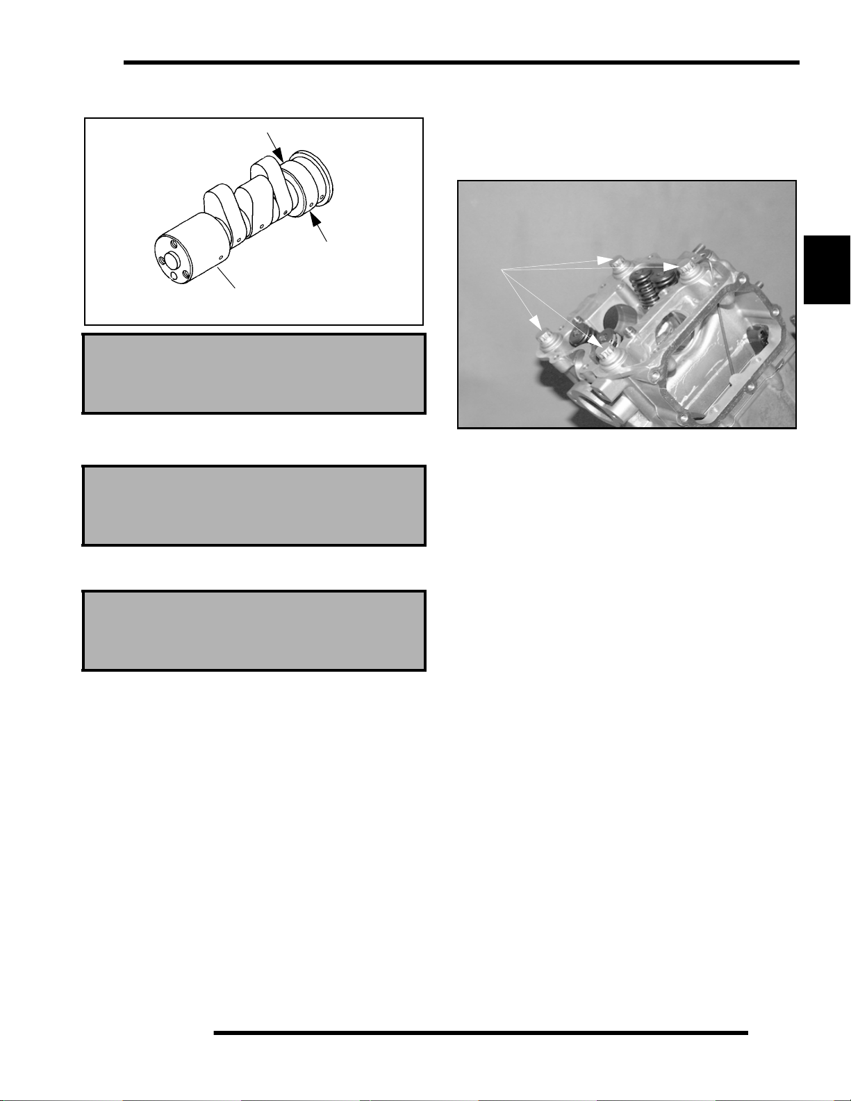
ENGINE
3. Measure height of each cam lobe using a micrometer.
Compare to specifications.
Journal O.D
Journal
Camshaft Journal O.D.:
Mag & PTO End: 1.4935-1.4941”
(37.935- 37.950 mm)
4. Measure camshaft journal outside diameter (O.D.)
5. Measure ID of camshaft journal bore.
Camshaft Journal I.D.:
Mag & PTO End: 1.4963-1.4970”
(38.005- 38.025 mm)
Cylinder Head Removal
1. Remove the two 6mm flange bolts (A) from cylinder head.
See next exploded view on next page.
2. Loosen each of the four cylinder head bolts (B) evenly 1/8
turn each time in a criss-cross pattern until loose.
B
3
3. Remove bolts (B) and tap cylinder head lightly with a
plastic hammer until loose. CAUTION: Tap only in
reinforced areas or on thick parts of cylinder head casting
to avoid damaging the thread.
4. Remove cylinder head and head gasket.
Calculate oil clearance by subtracting journal OD from
journal bore ID. Compare to specifications.
Camshaft Oil Clearance:
Std: .0022-.0035” (.055-.090 mm)
Limit: .0039” (.10 mm)
NOTE: Replace camshaft if damaged or if any part is
worn past the service limit.
NOTE: Replace cylinder head if camshaft jo urnal bore is
damaged or worn excessively.
3.19
Page 78

ENGINE
Cylinder Head Exploded View, EH50PL
EH50PL
A
3.20
Page 79

ENGINE
Cylinder Head Inspection
(A)
1. Thoroughly clean cylinder head (A) surface to remove all
traces of gasket material and carbon.
CAUTION
Use care not to damage sealing surface.
Cylinder Head Warp
Cylinder Head Disassembly
WARNING
Wear eye protection or a face shield d uring cylinder
head disassembly and reassembly.
NOTE: Keep all parts in order with respect to their
location in the cylinder head.
3
A
1. Using a valve spring compressor (A ), compress the valve
springs and remove the split keeper. NOTE: To prevent
loss of tension, do not compress the valve spring more than
necessary.
Cylinder Head Warp Limit:
.002” (.05 mm)
1. Lay a straight edge across the surface of the cylinder head
at several different points and measure warpage by
inserting a feeler gauge between the straight edge and the
cylinder head surface. If warpage exceeds the service limit,
replace the cylinder head.
A
2. Remove spring retainer and spring.
NOTE: The valve springs should be positioned with the
tightly wound coils against the cylinder head on
progressively wound springs (A).
3. Push valve out, keepin g it in order for reassembly in the
same guide.
3.21
Page 80

ENGINE
4. Measure free length of spring with a Vernier caliper. Check
spring for squareness. Compare to specifications. Replace
spring if either measurement is out of specification
5. Remove valve seals. CAUTION: Replace seals whenever
the cylinder head is disassembled. Hardened, cracked or
worn valve seals will cause excessive oil consumption and
carbon buildup.
seat area (B). NOTE: The valves cannot be re-faced or end
ground. V alves must be replaced if worn, bent, or damaged.
Measure valve stem in several places
Intake: .2343-.2348” (5.950-5.965 mm)
Exhaust: .2341-.2346” (5.945-5.960 mm)
5. Measure diameter of valve stem with a micrometer in three
places and in two different directions (six measurements
total). Compare to specifications.
Valve Stem Diameter:
Valve Inspection
1. Remove all carbon from valve with a soft wire wheel.
2. Check valve face for runout, pitting, and burnt spots. To
check for bent valve stems, mount valve in a drill or use “V”
blocks and use a dial indicator.
A
B
Valve Guide I.D.:
.2362-.2367” (6.0-6.012 mm)
6. Measure valve guide inside diameter at the top middle and
end of the guide using a small hole gauge and a micrometer.
Measure in two directions, front to back and side to side.
7. Subtract valve stem measurement to obtain stem to guide
clearance.
NOTE: Be sure to measure each guide and valve
combination individually
8. Replace valve and/or guide if clearance is
excessive.Compare to specifications.
NOTE: If valve guides are replaced, valve seats must be
reconditioned. Refer to Valve Seat Reconditioning for
procedure.
3. Check end of valve stem for flaring, pitting, wear or damage
(A).
4. Inspect split keeper groove for wear or flaring of the keeper
3.22
Page 81

ENGINE
Combustion Chamber
Clean all accumulated carbon deposits from combustion
chamber and valve seat area with a soft wire brush.
Valve Seat ReconditionING
Valve Seat Inspection
Inspect valve seat in cylinder head for pitting, burnt spot s,
roughness, and uneven surface. If any of the above
conditions exist, the valve seat must be reconditioned. If
the valve seat is cracked the cylinder head must be
replaced.
Cylinder Head Reconditioning
NOTE: Servicing the valve guides and valve seats
requires special tools and a thorough knowledge of
reconditioning techniques. Follow the instructions
provided in the cylinder head service tool kit.
CAUTION
3. Heat cylinder head in an oven or use a hot plate to bring
cylinder head temperature to 212
o
F (100o C).
CAUTION
Do not use a torch to heat cylinder head or warpage m ay
result from uneven heating. Head temperature can be
checked with a pyrometer or a welding temperature
stick. Wear the appropriate safety equipment for
working with heated metal.
Follow the manufacturers instructions provided with the
valve seat cutters in the Valve Seat Reconditioning Kit (PN
2200634). Abrasive stone seat reconditioning equipment
can also be used. Keep all valves in order with their
respective seat.
Too Uneven Good Too
Wide
NOTE: Valve seat width and point of contact on the
valve face is very important for proper sealing. The valve
must contact the valve seat over the entire
circumference of the seat, and the seat must be the
proper width all the way around. If the seat is uneven,
compression leakage will result. If the seat is too wide,
seat pressure is reduced, ca using carbon accumulation
and possible compression loss. If the seat is too narrow,
heat transfer from valve to seat is reduced and the valve
may overheat and warp, resulting in burnt valves.
Narrow
3
Wear eye protection when performing cylinder head
service. Valve guide replacement will require heating of
the cylinder head. Wear gloves to prevent burns.
Valve Guide Removal/Installation
1. Remove all carbon deposits from the combustion chamber,
valve seat and valve guide area before attempting to
remove valve guides.
CAUTION
Carbon deposits are extremely abrasive and may
damage the valve guide bore when guides are re moved.
2. Place new valve guides in a freezer for at least 15 minutes
while heating cylinder head.
1. When thoroughly heated, place cylinder head on blocks of
wood which will allow the old guides to be removed.
2. Using valve guide driver, drive guides out of the cylinder
head from the combustion chamber side. Be careful not to
damage guide bore or valve seat when removing guides.
3.23
Page 82

ENGINE
3. Place cylinder head on cylinder head table. NOTE: Be sure
cylinder head is still at 212
new guides.
Valve Guide Installed Height
Valve Guide Height:
.689-.709” (17.5-18.0 mm)
4. Place a new guide in the valve guide installation tool and
press guide in to proper depth. Check height of each guide
above the cylinder head (A). NOTE: The guide can also be
driven in to the proper depth. Inspect the guide closely for
cracks or damage if a driver is used.
Reaming The Valve Guide
o
F (100o C) before installing
8. Apply cutting oil to valve seat and cutter.
9. Place 46
10. Inspect the cut area of the seat.
• If the contact area is less than 75% of the
• If the cutter now contacts the uncut portion of the
• If the contact area of the cutter is in the same
o
cutter on the pilot and make a light cut.
circumference of the seat, rotate the pilot 180
make another light cut.
seat, check the pilot. Look for burrs, nicks, or
runout. If the pilot is bent it must be replaced.
place, the valve guide is distorted from improper
installation and must be replaced. Be sure the
cylinder head is at the proper temperature and
replace the guide.
o
and
5. Allow cylinder head to cool to room temperature. Apply
cutting oil to the reamer. Guides should be reamed from the
valve spring side of the cylinder head. Ream each guide to
size by turning the reamer clockwise continually. Continue
to rotate reamer clockwise during removal of the tool.
6. Clean guides thoroughly with hot soapy water and a nylon
brush. Rinse and dry with compressed air. Apply clean
engine oil to guides.
7. Install pilot in to valve guide.
• If the contact area of the initial cut is greater than
75%, continue to cut the seat until all pits are
removed and a new seat surface is evident.
NOTE: Remove only the amount of material
necessary to repair the seat surface.
(A)
11. To check the contact area of the seat on the valve face, apply
a thin coating of Prussian Blue™ paste to the valve seat. If
using an interference angle (46
marker to the entire valve face (A).
12. Insert valve into guide and tap valve lightly into place a few
times.
o
) apply black permanent
3.24
Page 83

ENGINE
13. Remove valve and check where the Prussian Blue™
indicates seat contact on the valve face. The valve seat
should contact the middle of the valve face or slightly
above, and must be the proper width.
• If the indicated seat contact is at the top edge of
the valve face and contacts the margin area(B) it is
too high on the valve face. Use the 30
lower the valve seat.
• If too low use the 60
seat. When contact area is centered on the valve
face, measure seat width.
• If the seat is too wide or uneven, use both top and
bottom cutters to narrow the seat.
• If the seat is too narrow, widen using the 45
and re-check contact point on the va lve face and
seat width after each cut.
Valve Seat Width:
Intake Std: .028” (.7 mm)
Limit: .055” (1.4 mm)
Exhaust Std: .039” (1.0 mm)
Limit: .071” (1.8 mm)
o
or 75o cutter to raise the
o
cutter to
o
cutter
NOTE: When using an interference angle, the seat
contact point on the valve will be very narrow, and is a
normal condition. Look for an even and continuous
contact point on the black marker, all the way around the
valve face.
14. Clean all filings from the area with hot soapy water, rinse,
and dry with compressed air.
15. Lubricate the valve guides with clean engine oil, and apply
oil or water based lapping compound to the face of the
valve. Lapping is not required with an interference angle.
16. Insert the valve into its respective guide and lap using a
lapping tool or a section of fuel line connected to the valve
stem.
17. Rotate the valve rapidly back and forth until the cut sounds
smooth. Lift the valve slightly off of the seat, rotate 1/4 turn,
and repeat the lapping process. Do this four to five ti mes
until the valve is fully seated, and repeat process for the
other valve(s).
A
3
Bottom - 60o or 75o
Seat
Width
Seat - 45
o
or 46
Top - 30
18. Clean cylinder head, valves, and camshaft oil supply
passage (A) thoroughly.
19. If oil passage blind plug was removed, apply Crankcase
o
o
Sealant (PN 2871557) or equivalent sealer to the threads
and install, torquing to 8 ft. lbs. (11 Nm).
CAUTION
Do not allow sealant to enter oil passage.
20. Spray electrical contact cleaner into oil passage and dry
using compressed air.
3.25
Page 84

ENGINE
Cylinder Head Assembly
CAUTION
Wear eye protection during assembly.
NOTE: Assemble the valves one at a time to maintain
proper order.
1. Install new valve seals on valve guides.
2. Apply engine oil to valve guides and seats.
3. Coat valve stem with molybdenum disulfide grease.
4. Install valve carefully with a rotating motion to avoid
damaging valve seal.
5. Dip valve spring and retainer in clean engine oil and install
spring with closely spaced coils toward the cylinder head.
Valve Sealing Test
1. Clean and dry the combustion chamber area.
2. Pour a small amount of clean, high flash point solvent into
the intake port and check for leakage around each intake
valve. The valve seats should hold fluid with no seepage.
3. Repeat for exhaus t valves by pouring fluid into exhaust
port.
Valve Clearance Adjustment
Feeler gauge for both valves
NOTE: The valves share a common rocker arm, and
must be adjusted using two feeler gauges.
1. Insert .006 feeler gauge(s) between end of exhaust valve
stem and adjuster screw(s).
2. Loosen locknut(s) and turn adjuster screw(s) until there is
a slight drag on feeler gauge(s). The Valve/Clutch Adjuster
Tool (PA-44689) can be used to adjust the 500 engines
valves.
NOTE: Both feeler gauges should remain inserted
during adjustment of each valve
6. Place retainer on springs and install valve spring
compressor. Compress spring only enough to allow split
keeper installation and prevent loss of spring tension.
Install split keepers with the gap even on both sides.
7. Repeat procedure for remaining valve.
8. When all valves are installed, tap lightly with soft faced
hammer on the end of the valves to seat the split keepers.
3.26
VALVE CLEARANCE
.006” (.15 mm)
3. When clearance is correct, hold adjuster screw and tighten
locknut securely
4. Re-check the valve clearance.
5. Repeat adjustment procedure if necessary until clearance is
correct with locknut secured.
Page 85

ENGINE
Cylinder/Piston Removal and Inspection
NOTE: Follow engine disassembly procedures to
remove valve cover, camshaft and rocker arms, and
cylinder head.
1. Remove cam chain guide at front of cylinder.
4. Remove the two 6 mm cylinder base bolts.
3
5. Loosen each of the four large cylinder base bolts 1/4 turn
at a time in a criss-cross pattern until loose and remove
bolts.
NOTE: The bolts are inside the water jacket.
2. Loosen all four oil pipe banjo bolts and then rem ove the
bolts and eight sealing washers. Remove the pipes.
3. Loosen hose clamps and remove coolant in let hose.
6. Tap cylinder lightly with a plastic hammer in the reinforced
areas only until loose.
7. Rock cylinder forward and backward and lift it from the
crankcase, supporting piston and connecting rod. Support
piston with Piston Support Block (PN 2870390).
8. Remove dowel pins from crankcase.
3.27
Page 86

ENGINE
Piston Removal
1. Remove circlip. Note piston directional arrow pointing
toward the right (Mag) side of engine.
1. Remove piston circlip and push piston pin out of piston. If
necessary, heat the crown of the piston slightly with a
propane torch.
2. Remove top compression ring.
*By hand: Placing both thumbs as shown, spread th e ring open
and push up on the opposite side. Do not scratch the ring lands.
A
3. Repeat procedure for second ring.
The oil control ring is a three piece design consisting of a top and
bottom steel rail and a center expander section. The top rail has
a locating tab on the end which fits into a notch (A) in the upper
oil ring land of the piston.
4. Remove the top rai l first followed by the bottom rail.
5. Remove the expander.
CAUTION
Do not apply heat to the piston rings. The ring may
lose radial tension
*Using a piston ring pliers: Carefully expand ring and lift it off
the piston.
CAUTION
Cylinder Inspection
1. Remove all gasket material from the cylinder sealing
surfaces.
2. Inspect the top of the cylinder for warpage using a straight
edge and feeler gauge.
Cylinder Warp Limit:
.002” (.05 mm)
Do not expand the ring more than necessary to
remove it from the piston or the ring may break
3.28
Page 87

ENGINE
3. Inspect cylinder for wear, scratches, or damage.
1/2” Down From Top of Cylinder
X
X
X
1/2” Up From Bottom
4. Inspect cylinder for taper and out of round with a
telescoping gauge or a dial bore gauge. Measure in two
different directions, front to back and side to side, on three
different levels (1/2” down from top, in the middle, and 1/
2” up from bottom).
5. Record measurements. If cylinder is tapered or out of round
beyond .002, the cylinder must be re-bored oversize or
replaced.
Y
Y
Y
2. Subtract this measurement from the maximum cylinder
measurement obtained in Step 5 above.
Piston to Cylinder Clearance
Std: .0006- .0018” (.015- .045 mm)
Piston O.D.:
Std: 3.6204- 3.6215” (91.970-91.985 mm)
Piston/Rod Inspection
Piston Pin Bore
Piston Pin Bore:
3
Cylinder Taper
Limit: .002 Max.
Cylinder Out of Round
Limit: .002 Max.
Standard Bore Size:
3.6221-3.6228” (92.00 - 92.012 mm)
Piston-to-Cylinder Clearance
Piston
40 mm
Piston Pin
1. Measure piston outside diameter at a point 40 mm down
from the top of the piston at a right angle to the direction
of the piston pin.
.9055-.9057” (23.0-23.006 mm)
1. Measure piston pin bore.
Piston Pin Measurement Locations
Piston Pin O.D.
.9053-.9055” (22.994-23.0 mm)
3.29
Page 88

ENGINE
Piston Ring Installed Gap
1. Place each piston ring inside cylinder using piston to push
ring squarely into place as shown at right.
Feeler Gauge
2. Measure piston pin O.D. Replace piston and/or piston pin
if out of tolerance.
3. Measure connecting rod small end ID.
Piston
Ring
Feeler Gauge
Piston Ring-to-Groove Clearance
Top Ring Std: .0016-.0031” (.040-.080 mm)
Limit: .0059” (15 mm)
Second Ring Std: .0012-.0028” (.030-.070 mm)
Limit: .0059” (15 mm)
4. Measure piston ring to groove clearance by placing the ring
in the ring land and measuring with a thickness gauge.
Replace piston and rings if ring-to-groove clearance
exceeds service limits
Cylinder
Piston Ring
Piston Ring Installed Gap
Top Ring
Std: .0079- .0138” (.20- .36 mm)
Limit: .039” (1.0 mm)
Second Ring
Std: .0079- .0138” (.20- .36 mm)
Limit: .039” (1.0 mm)
Oil Ring
Std: .0079- .0276” (.20- .70 mm)
Limit: .059” (1.5 mm)
2. Measure installed gap with a feeler gauge at both the top
and bottom of the cylinder.
NOTE: A difference in end gap indicates cylinder taper.
The cylinder should be measured for excessive taper
and out of round
3. If the bottom installed gap measurement exceeds the
service limit, replace the rings. If ring gap is below
specified limit, file ring ends until gap is within specifi ed
range.
NOTE: Always check piston ring installed gap after reboring a cylinder or when installing new rings. A re-bored
cylinder should always be scrubbed thoroughly with hot
soapy water, rinsed, and dried completely. Wipe cylinder
bore with an oil rag immediately to remove residue and
prevent rust.
25-50 mm
3.30
Crankcase Disassembly
NOTE: The recoil starter, starter motor , starte r drive, flywheel,
stator, cam chain and sprockets can be serviced with the engine
in the frame.
Page 89

ENGINE
Starter Drive Removal/Inspection
1. Remove recoil housing bol ts and rem ove housing.
2. Remove starter drive assembly. Note the thrust washer
located at the rear of the drive mechanism.
3. Inspect the thrust washer for wear or damage and replace
if necessary.
A
5. Measure the ID of the bushing in the recoil housing (A) and
in the crankcase and record. Measure in two directions 90
apart to determine if bushing is out of round. Calculate
bushing clearance. Replace bushing if clearance exceeds
the service limit.
6. Inspect gear teeth on starter drive. Replace starter drive if
gear teeth are cracked, worn, or broken.
Flywheel/Stator Removal/Inspection
1. Remove flywheel nut and washer.
2. Install Flywheel Puller (PN 2871043) and remove
flywheel.
CAUTION
Do not thread the puller bolts into the flywheel more
than 1/4" or stator coils may be damaged
3. Mark or note position of stator plate on crankcase.
4. Remove bolts and carefully remove stator assembly, being
careful not to damage crankshaft bushing on stator plate.
5. Replace crankshaft seal (A).
A
o
3
.4735”-.4740” (11.11-12.04 mm)
Std. Bushing ID:
Std. Shaft OD:
.470”-.472” (11.93-11.99 mm)
Starter Drive Bushing Clearance:
Std: .0015-.004” (.038-.102 mm)
Service Limit:
.008” (.203 mm)
4. Measure the OD of the starter drive shaft on both ends and
record.
6. Remove oil passage O-Ring (B).
B
3.31
Page 90

ENGINE
7. Remove large sealing O-Ring from outer edge of stator
plate.
Cam Chain/Tensioner Blade
1. Remove bolt securing tensioner blade to crankcase (A).
A
section of chain. Replace if worn past service limit.
Chain Service Limit: 5.407” (13.7 cm)
4. Using the special socket, remove the crankshaft slotted nut.
NOTE: The cran ksh a ft slot te d nu t is a left-hand thread.
5. Remove cam chain drive sprocket and woodruff key from
crankshaft.
6. Inspect sprocket teeth for wear or damage.
7. Inspect woodruff key for wear.
8. Replace any worn or damaged parts.
One Way Valve Removal
The one way valve prevents oil from draining ou t of the oil
tank and into the crankcase when the engine is off. It must
be clean and have adequate spring pressure in order to
seal properly.
D
C
B
A
2. Remove blade and inspect for cracks, wear, or damage.
B
20 Pitch Section
3. Remove cam chain (B ). Inspect chain for worn or missing
rollers or damage. Stretch chain tight on a flat surface and
apply a 10 lb. (4.53 kg) load. Measure length of a 20 pitch
1. Remove cap bolt (A), sealin g washer (B), spring (C), and
one way valve (D) from PTO side crankcase.
2. Inspect free length of spring and check coils for distortion.
One Way Valve Spring Free Length:
Std: 1.450” (3.68 cm)
3. Inspect valve for wear.
4. Check seat area for nicks or foreign material that may
prevent proper sealing of valve.
3.32
Page 91

ENGINE
Crankcase Separation
1. Remove flange bolts (10) from magneto side crankcase
evenly in a criss-cross pattern.
2. Separate crankcase by tapping with a soft faced hammer in
reinforced areas.
3. Tap lightly on balancer gear with a brass drift through th e
hole in the crankcase if necessary, to ensure the balancer
shaft stays in the PTO side crankcase. Watch the gap along
the crankcase mating surface and separate the crankcase
evenly. It may also be necessary to tap the oil pump shaft
lightly to separate the crankcase.
3. Inspect drive gear teeth for cracks, damage or excessive
wear.
3
4. Remove three oil pump retai ning bolts and pump.
5. Inspect mating surface of crankcase and oil pump. Check
for nicks, burrs, or surface irregularities.
CAUTION
Do not strike the oil pump shaft at an angle or the
shaft may bend, causing irreparable damage. Tap
only lightly on the pump shaft if necessary.
4. Remove the Mag (RH) crankcase from the PTO case.
Oil Pump Removal/Inspection
C
A
B
1. Remove pump shaft bearing (A) and thrust washer (B)
from pump shaft.
2. Remove (2) bolts holding pump drive gear (C).
6. Remove the three screws and strainer screen from pump.
7. Clean screen thoroughly.
8. Remove pump body screw and feed chamber cover.
3.33
Page 92

ENGINE
9. Measure pump end clearance using a feeler gauge and
straight edge.
Pump End Clearance:
Std: .001 -.003 (.0254-.0762 mm)
Wear Limit: .004 (.1016 mm)
10. Measure clearance between outer feed rotor and pump body
with a feeler gauge.
Oil Pump Assembly
1. Clean and dry all parts thoroughly. Apply clean engine oil
to all parts. Do not use gasket sealer on the pump body
mating surfaces or oil passages will become plugged.
2. Install pump shaft and scavenge rotor drive pin.
3. Install outer scavenge rotor, inner scavenge rotor, and
scavenge casing.
4. Install outer feed rotor and inner feed rotor drive pin.
5. Install inner feed rotor and feed chamber cover with screw.
6. Tighten screw securely.
7. Install screen on pump body.
8. Install oil pump on crankcase and torque bolts to 6 ft . lbs.
(8 Nm).
Oil Pump Attaching Bolt Torque:
6 ft. lbs. (8 Nm)
Counter Balancer Shaft Removal/Inspection
1. Remove the shim washer (A) from the counter balancer
shaft.
A
Rotor Tip Clearance:
Std: .005 (.127 mm)
Wear Limit: .008 (.2032 mm)
11. Measure rotor tip clearance with a feeler gauge.
12. Remove inner and outer feed rotor and pump chamber
body.
13. Repeat measurements for scavenge rotor.
14. Remove inner and outer scavenge rotor and inspect pump
shaft for wear.
3.34
2. Note the alignment dots on the balancer and crankshaft
gears, the marks must be aligned during reassembly.
Page 93
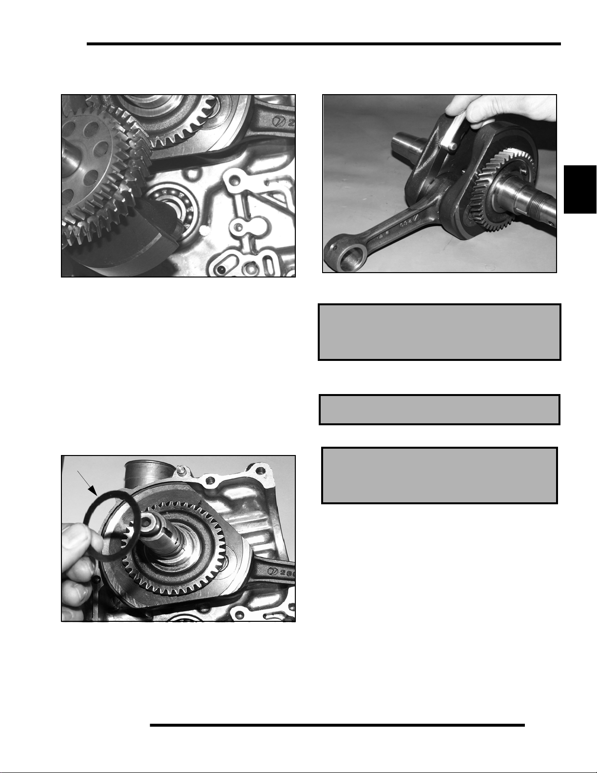
ENGINE
3. Turn the shaft until balancer counter weights clear the
crankshaft and remove the balancer shaft from the
crankcase.
4. Inspect the balancer drive gear and pump shaft drive gear.
5. Replace the shaft if gear teeth are abnormally worn or
damaged.
6. Inspect the balancer shaft bearings.
NOTE: Due to extremely close tolerances and minimal
wear, the balancer shaft ball bearings must be inspected
visually and by feel. Look for signs of discoloration,
scoring or galling. Turn the inner race of each bearing.
The bearings should turn smoothly and quietly. The outer
race of each bearing should fit tightly in the crankcase.
The inner race should be firm with minimal side to side
movement and no detectable up and down movement.
Crankshaft Removal/Inspection
A
8. Support the PTO side crankcase and crankshaft; press the
crankshaft out. Be careful not to damage the crankcase
mating surface or connecting rod.
3
9. Use a feeler gauge to measure the connecting rod big end
side clearance.
Connecting Rod Big End Side Clearance:
Std: .0039-.0256” (.1-.65 mm)
Limit: .0315” (.80 mm)
10. Place the crankshaft in a truing stand or V-blocks and
measure the runout on both ends with a dial indicator.
Max Runout: .0024” (.06 mm)
11. Measure the connecting rod big end radial clearance.
Big End Radial Clearance:
Std: .0004-.0015” (.011-.038 mm)
Limit: .0020” (.05 mm)
7. Remove the shim washer (A) from the crankshaft.
12. Inspect the crankshaft main bearing journals for scoring
and abnormal wear.
3.35
Page 94

ENGINE
Crankcase Bearing Inspection
1. Remove the seal from the PTO side crankcase.
2. Inspect the crankshaft main bearings, balancer shaft
bearings, and pump shaft bearing.
NOTE: Due to extremely close tolerances and minimal
wear, the bearings must be inspected visually, and by
feel. Look for signs of discoloration, scoring or galling.
Turn the inner race of each bearing. The bearings should
turn smoothly and quietly . The outer race of e ach bearing
should fit tightly in the crankcase. The inner race should
be firm with minimal side to side movement and no
detectable up and down movement.
3. Support the crankcase and drive or press the main bearings
out of each crankcase.
4. To remove balancer shaft bearings and pump shaft bearing
use a blind hole bearing puller.
NOTE: Bearings are stressed during the removal
process and should not be re-used!
Pump Shaft Oil Seal/W ater Pump Mechanical Seal Removal (Engine Disassembled)
NOTE: The water pump mechanical seal can be
removed without removing the engine. Refer to Water
Pump Mechanical Seal Installation.
Replace the pump shaft seal and water pump mechanical
seal whenever the crankcase is disassembled.
1. Remove the pump shaft bearing from the Magneto (right
hand) side crankcase.
2. Pry out the oil seal, noting the direction of installation with
the spring side facing IN (toward inside of case).
3. Drive the water pump mechanical seal out of the crankcase
from inside to outside. Note: The new mechanical seal must
be installed after
special tool. See Mechanical Seal Installation.
the crankcases are assembled, using a
Crankcase Inspection
1. Remove all traces of gasket sealer from the crankcase
mating surfaces. Inspect the surfaces closely for nicks,
burrs or damage.
2. Check the oil pump and oil passage mating surfaces to be
sure they are clean and not damaged.
3.36
Page 95

ENGINE
Bearing Installation
NOTE: To ease bearing installation, warm the
crankcase until hot to the touch. Place the bearings in a
freezer.
1. Install the bearings so the numbers are visible.
2. Drive or press new bearings into the crankcases, using the
proper driver.
CAUTION
Press only on outer race of bearing
to prevent bearing damage
• 70 mm (2.755") driver- For crankshaft main
bearings.
• 46 mm (1.810") For counter balancer bearings.
• 28 mm (1.100") For pump shaft bearing.
End Play Inspection/Adjustment
Before reassembling the crankcase,the following steps should
be performed to determine the amount of crankshaft, counter
balancer shaft, and pump shaft end play . Excessive end play may
cause engine noise at idle and slow speeds. Too little play will
side load the bearings which may lead to premature bearing
failure.
4. Measure the distance from the PTO crankcase mating
surface to the main bearing using a dial caliper and a
straight edge.
3
5. Subtract the thickness of the straightedge from the
measurement obtained in Step 2 and record.
Crankshaft End Play Adjustment
3. Make sure all bearings are firmly seated in the both Mag
and PTO crankcase.
PTO Case Depth_________________________
3.37
Page 96

ENGINE
6. Measure the distance from the Magneto crankcase mating
surface to the main bearing using the same method and
record.
7. Subtract the thickness of the straightedge from the
measurement obtained in Step 4 and record.
Mag Case Depth_______________
10. Subtract the Crankshaft Width measured in S tep 7 from the
Total Case Width recorded in Step 6, and record below.
Total End Play_____________
11. Subtract the thickness of the existing shim from the result
of Step 8 to determine if a different shim is required. The
result must be within the specified range listed.
Crankshaft End Play: .008-.016” (.02-.04 cm)
Counter Balancer Shaft End Play Adjustment.
8. Add the readings recorded in Step 3 and Step 5 and record
below.
Total Case Width_________________
9. Measure the width of the crankshaft at the bearing seats
with a micrometer or dial caliper and record.
12. Make sure all bearings are firmly seated in the crankcase.
13. Measure the width of the counter balancer shaft at the
bearing seats with a dial caliper or micrometer, and record
reading.
Crankshaft Width____________
3.38
Page 97

ENGINE
14. Measure the distance from the Mag crankcase mating
surface to the balance shaft bearing using a dial caliper and
a straight edge. Subtract the thickness of the straightedge
and record.
15. Measure the distance from the PTO crankcase mating
surface to the bearing using the same method outlined in
Step 1, 2, and-3.
16. Add the readings obtained in Step 3 and Step 4.
17. Subtract the counter balancer shaft width measured in Step
2 from the figure obtained in Step 5.
18. Subtract the thickness of the existing shim from the result
of Step 6 to determine if a different shim is needed. The
result must be within the specified range listed at below.
Counter Balance Shaft End Play:
.008”-.016” (.02-.04 cm)
Oil Pump Shaft End Play Adjustment
1. Make sure the pump shaft bearing is firm ly seated in the
Magneto side crankcase.
3. Install the gear on the oil pump and measure the width of
the pump and gear. Subtract this measurement from the
measurement recorded in Step 2.
4. Subtract the thickness o f the ex isting shim from th e result
of Step 3 to determine if a different shim is needed. See
Shaft End Play Spec.
Oil Pump Shaft End Play:
.008”-.016” (.02-.04 cm)
3
2. Measure the distance from the magneto crankcase mating
surface to the bearing using a dial caliper and a straight
edge. Subtract the thickness of the straightedge and record.
3.39
Page 98

ENGINE
ENGINE REASSEMBLY
Pump Shaft Oil Seal Inst allation
1. Install the seal from the outside of the crankcase (water
pump side) with the spring facing inward, toward the pump
shaft bearing.
2. Drive or press the seal into place using a 25 mm (.985") seal
driver, until flush with the outer edge of the seal bore.
3. Lubricate the seal lip with grease.
Crankshaft/Counter Balance/Oil Pump Installation
Lubricate all bearings with clean engine oil before
assembly.
Use the Crankshaft/Water Pump Installation Kit (PN
2871283) to prevent damage to the crankshaft and main
bearings during installation.
1. Install the crankshaft into the PTO side crankcase. Screw
the threaded rod into the crankshaft until the threads are
engaged a minimum of one inch (25.4mm).
2. Install the collar, washer, and nut onto the threaded rod.
Hold the crankshaft and tighten the nut to draw the
crankshaft into the main bearings until fully seated. Loosen
the nut and remove the threaded rod from the crankshaft.
If removal is difficult, install two nuts on the end of the
threaded rod and tighten against each other.
3. Install the proper shim on the magneto end of the
crankshaft.
4. Place the balancer shaft in the PTO crankcase aligning the
timing marks on the crankshaft and balancer gears. Install
the proper shim washer on the shaft.
5. Inspect the oil pump sealing surface on the crankcase.
Apply a light film of engine oil to the surface and install the
oil pump.
NOTE: Do not use gasket sealer on the pump mating
surfaces.
NOTE: After engine is assembled and machine is
readied for field operation, oil pump MUST be primed.
Follow oil pump priming procedure.
Oil Pump Bolt Torque:
6 ft. lbs. (8 Nm)
6. Align the drive gear with the drive pin on the pump shaft
and install the gear. Be sure the gear is fully seated and
properly engaged.
7. Install the proper shim washer on the pump shaft.
3.40
Page 99

ENGINE
Crankcase Assembly
1. Apply Crankcase Sealant (PN 2871557 ) to the crankcase
mating surfaces. Be sure the alignment pins are in place.
2. Set the crankcase in position carefully to avoid damaging
the pump shaft seal, and install the magneto end crankshaft
installation tool (follow instructions provided with the
Crankshaft/Water Pump Installation Kit (PN 2871283).
Draw the crankcase halves together by tightening the nut
on the tool and tapping lightly in the pump shaft area with
a soft faced hammer to maintain alignment. Continually
check alignment of the cases during installation, closing the
gap equally until the surfaces are tightly seated.
3. Remove the tool.
4. Install the crankcase flange bolts and tighten in 3 steps
following the pattern to specified torque.
Crankcase Bolt Torque:
14 ft. lbs. (19 Nm)
Crankcase Sealant:
(PN 2871557)
Water Pump Mechanical Seal Installation
Water Pump Mechanical Seal Removal Engine Installed
Water Pump Mechanical Seal
Puller: (PN 2872105)
Replacement T-Handle:
(PN 2872106)
This tool allows a technician to replace the mechanical
water pump seal on EH50PL engines without removing
the engine and splitting the cases.
3
CAUTION
Improper or careless use of this tool or procedure
can result in a bent water pump shaft.Pump shaft
replacement requires engine removal and
crankcase separation. Use caution while performing
this procedure. Make sure that the puller is parallel
to the shaft at all times. Do not place side loads on
the water pump shaft or strike the puller or shaft in
any way.
1. After the coolant has been drained, remove the water pump
cover, impeller and the sealing washer. (Ill. 1).
Sealing Washer
5. Clean the seal cavity to remove all traces of old sealer.
6. Place a new mechanical seal in the seal drive collar, and
install on the pump shaft.
7. Screw the guide onto the end of the pump shaft.
8. Install the washer and nut and tighten to draw seal into place
until fully seated.
9. Remove the guide adaptor using the additional nut as a jam
nut if necessary.
Sealing Washer
(Copper or Aluminium)
Coolant Drain
Bolt
III. 1
Oil
Seal
Impeller
Mechanical Seal
3.41
Page 100

ENGINE
2. Slide the main puller body over the outer portion of the
mechanical seal as shown in Ill. 2 and turn T-Handle
clockwise until it contacts water pump shaft. Continue
rotating until outer portion of mechanical seal is separated
from the metal seal body.
T-Handle
Main Puller Body
III. 2
3. Insert the puller legs between the water pump drive sh aft
and the remaining portion of the mechanical seal. Attach
the puller legs to the main puller body. Ill. 3
Main puller
body
5. Tighten the hex socket screws on the puller legs sufficiently
so the lip of the puller legs will grasp the mechanical seal.
Ill. 5.
T-Handle
Main Puller Body
III. 5
6. Turn the puller T-Handle clockwise unti l it contacts the
water pump shaft. Continue rotating until the remaining
portion of mechanical seal has been removed from the
cases. Ill. 6 Pump shaft oil seal can also be replaced at this
time if necessary.
7. The Water Pump Install Kit (PN 5131135) is required to
install the new mechanical seal. This tool is available
separately and it is also included in the Crankshaft/Water
Pump Seal Installation Kit (PN 2871283).
Position the split
o
to opening
90
on main puller
body
III.3
4. Ensure that the split between the puller legs are fully
supported by the main body of the tool (Ill 4).
Hex Socket Screws
Puller Legs
One Way Valve Installation
Install the one way valve plung er , spring, and plug using a
new sealing washer.
One Way Valve Plug Torque:
16 ft. lbs. (22 Nm)
III. 4
3.42
Lip must grasp inside of
mechanical seal
 Loading...