

Page 1

SCRAMBLER 50
SCRAMBLER 90
SPORTSMAN 90
PREDATOR 90
SERVICE MANUAL
PN 9918068
The Way Out.
Page 2

2003 Scrambler 50, Predator 90, Scrambler 90 , Sportsman 90
SERVICE MANUAL
Foreword
This manual is designed primarily for use by certified Polaris Master Service Dealer technicians in a properly
equipped shop and should be kept available for reference. All references to left and right side of the vehicle
are from the operator’s perspective when seated in a normal riding position.
Some procedures outlined in this manual require a sound knowledge of mechanical theory, tool use, and shop
procedures in order to perform the work safely and correctly. Technicians should read the text and be familiar
with service procedures before starting the work. Certain procedures require the use of special tools. Use
only the proper tools as specified.
This manual includes procedures for maintenance operations, component identification and unit repair, along
with service specifications for the 2003 Polaris Scrambler 50, Predator 90, Scrambler 90, and Sportsman 90.
Comments or suggestions about this manual may be directed to: Service Publications Dept. @ Polaris Sales
Inc. 2100 Hwy 55 Medina Minnesota 55340.
2003 Sportsman Youth ATV Service Manual (PN 9918068)
ECopyright 2002 Polaris Sales Inc. All information contained within this publication is based on the latest product information at the
time of publication. Due to constant improvement in the design and quality of production components, some minor descrepancies may
result between the actual vehicle and the information presented in this publication. Depictions and/or procedures in this publication are
intended for reference use only. No liability can be accepted for omissions or inaccuracies. Any reprinting or reuse of the depictions
and/or procedures contained within, whether whole or in part, is expressly prohibited. Printed in U.S.A.
Page 3

UNDERSTANDING SAFETY LABELS AND INSTRUCTIONS
Throughout these instructions, important information is brought to your attention by the following symbols:
The Safety Alert Symbol means ATTENTION! BECOME ALERT! YOUR SAFETY IS INVOLVED!
DANGER
Failure to follow DANGER instructions will result in severe injury or death to the operator, bystander or person
inspecting or servicing the ATV.
WARNING
Failure to follow WARNING instructions could result in severe injury or death to the operator, bystander or
person inspecting or servicing the ATV.
CAUTION:
A CAUTION indicates special precautions that must be taken to avoid personal injury, or ATV or property
damage.
NOTE:
A NOTE provides key information to clarify instructions.
Trademarks
Polaris acknowledges the following products mentioned in this manual:
FLEXLOC, Registered Trademark of SPS Technologies
Loctite, Registered Trademark of the Loctite Corporation
STA-BIL, Registered Trademark of Gold Eagle
FOX, Registered Trademark of Fox Shox
Nyogel, Trademark of Wm. F. Nye Co.
Fluke, Registered Trademark of John Fluke Mfg. Co.
Mity Vac, Registered Trademark of Neward Enterprises, Inc.
Ammco, Registered Trademark of Ammco Tools, Inc.
Torx, Registered Trademark of Textron
Page 4

Table of Contents
PN 9918068
Chapter 1 General Information Maintenance
Chapter 2 Engine / Transmission / CVT
Chapter 3 Carburetion
Chapter 4 Body / Steering suspension
Chapter 5 Electrical
Page 5

GENERAL INFORMATION
CHAPTER 1
GENERAL INFORMATION
MAINTENANC
Serial Number Location 1.2.......................
2003 Youth Models 1.3...........................
Specifications 1.4................................
Publication Numbers 1.5..........................
Paint Codes 1.5.................................
Inspection Schedule 1.5..........................
Standard Torque Specifications 1.6................
Lubricant and Maintenance Products 1.6............
Special Tools 1.6.................................
Unit of Measure Conversion Table 1.7..............
Tap Drill Charts 1.8...............................
Decimal Equivalent Chart 1.8......................
Glossary of Terms 1.9............................
2003 Models E.S.L.S. 1.10.........................
Vehicle Inspection/Adjustments 1.11--1.13.................
Transmission Lubrication 1.13--1.14......................
Throttle Operation / Air Screw Adjustment 1.14.......
Idle Speed Adjustment 1.14........................
Throttle Cable / ETC Adjustments 1.15--1.16..............
Oil Pump Adjustment / Bleeding 1.16................
Oil Pump Troubleshooting 1.17.....................
Fuel System 1.17--1.18.................................
Compression Testing 1.19..........................
Air Filter Service 1.19..............................
Wheels and Tires 1.19--1.21.............................
Steering / Alignment 1.21--1.22..........................
E
/
1
1.1
Page 6
GENERAL INFORMATION
MODEL IDENTIFICATION
The machine model number must be used with any correspondence regarding warranty or service.
Machine Model Number Identification
A03EA05CA
Emissions &
Year Designation
VIN IDENTIFICA
World Mfg. ID
1 2 3 4 5 6 7 8 9 10 11 12 13 14 15 16 17
RF 3 E A
Basic Chassis
Designation Engine Designation
TION
Vehicle Descriptor
05C* 3T 0 00 000
Vehicle Identifier
Model Option
Body Style
Powertrain
SERIAL NUMBER LOCA
Whenever corresponding about an engine, be sure to refer to the engine serial number. This information can be
found stamped on the transmission section located by the transmission oil fill plug(A). The machine model
number and serial number are important for vehicle identification. The machine serial number is stamped on the
front of the frame (B).
A
Emissions
Engine
Check Digit
TIONS
Model
Year
Plant No.
Individual Serial No.
B
* This could be either
a number or a letter
Front
1.2
Page 7

GENERAL INFORMATION
2003 YOUTH MODEL ATVS
SCRAMBLER 50
SCRAMBLER 90
SPORTSMAN 90
PREDATOR 90
NOTE: Colors will vary upon model.
1.3
Page 8

GENERAL INFORMATION
1.4
Page 9

GENERAL INFORMATION
SPECIFICATIONS
MODEL
ENGINE TYPE 2-Stroke Horizontal
NUMBER OF CYLINDERS 1 1 1 1
DISPLACEMENT 49.3 cc 89.2 cc 89.2 cc 89.2 cc
BORE AND STROKE 1.58x1.54² (40x39.2
COMPRESSION RATIO 6.8:1 7.7:1 7.7:1 7.7:1
SPARK PLUG BPR7HS BPR7HS BPR7HS BPR7HS
ALTERNATOR OUTPUT 70 Watts @ 4000 RPM 70 Watts @ 4000 RPM 70 Watts @ 4000 RPM 70 Watts @ 4000 RPM
IGNITION TIMING ** 14° @ 1500 RPM** 16° @ 1500 RPM** 16° @ 1500 RPM** 16° @ 1500 RPM**
MAX. TORQUE 4 ft.lbs (5.4 Nm) @
CARBURETOR Sunworld H68K Mikuni VM16 Mikuni VM16 Mikuni VM16
STARTING Electric/Kick Start Electric/Kick Start Electric/Kick Start Electric/Kick Start
BATTERY GTX5L--BS, 4.85 amp GTX5L--BS, 4.85 amp GTX5L--BS, 4.85 amp GTX5L--BS, 4.85 amp
LUBRICATION Oil Injection Oil Injection Oil Injection Oil Injection
OIL CAPACITY 1.057 Quarts (1 Liter) 1.057 Quarts (1 Liter) 1.057 Quarts (1 Liter) 1.057 Quarts (1 Liter)
TRANSMISSION Automatic (C.V.T. Sys-
FRONT SUSPENSION A-arm with 4.25² (10.8
REAR SUSPENSION Single Shock/Swing
FRONT BRAKE Drum Drum Drum Drum
REAR BRAKE Drum Drum Drum Drum
PARKING BRAKE Mechanical Lock Mechanical Lock Mechanical Lock Mechanical Lock
FRONT TIRES 16x8-7 18x7-7 18x7-7 19x7-8
REAR TIRES 16x8-7 18x9.5-8 18x9.5-8 18x9.5-8
TIRE PRESSURE 2psi 3psi 3psi 3psi
OVERALL DIMENSIONS 54.6x34x34.7²
WHEELBASE 35.4² (90 cm) 38.5² (98 cm) 38.5² (98 cm) 38.5² (98 cm)
TURNING RADIUS 74.8² (190 cm) 98.4² (250 cm) 98.4² (250 cm) 98.4² (250 cm)
SEAT HEIGHT 22.5² (57 cm) 24.5² (62 cm) 24.5² (62 cm) 24.5² (62 cm)
GROUND CLEARANCE 3² (8 cm) 4² (10 cm) 4² (10 cm) 5² (12 cm)
DRY WEIGHT 211.6 lbs. (96 kg) 233.7 lbs. (106 kg) 233.7 lbs. (106 kg) 238.1 lbs. (108 kg)
MAX. LOAD CAPACITY 100 lbs. (45.4 kg) 160 lbs. (72 kg) 160 lbs. (72 kg) 190 lbs. (86 kg)
FUEL REQUIREMENTS 87 Octane Unleaded 87 Octane Unleaded 87 Octane Unleaded 87 Octane Unleaded
FUEL CAPACITY 1.32 Gallons (5 Liters) 1.32 Gallons (5 Liters) 1.32 Gallons (5 Liters) 1.32 Gallons (5 Liters)
FRONT RACK CAPACITY N/A N/A N/A 10 lbs. (4.54 kg)*
REAR RACK CAPACITY N/A N/A N/A 20 lbs. (9.08 kg)*
SCRAMBLER 50 SCRAMBLER 90 PREDATOR 90 SPORTSMAN 90
(AR03--01)
mm)
6000 RPM
tem)
cm) Travel
Arm with 4.25² (10.8
cm) Travel
(138.7x86.3x88.2 cm)
2-Stroke Horizontal
(AR07--01)
2.05x1.65² (52x42
mm)
6.5 ft.lbs (8.82 Nm) @
6000 RPM
Automatic (C.V.T. Sys-
tem)
A-arm with 4.25² (10.8
cm) Travel
Single Shock/Swing
Arm with 4.25² (10.8
cm) Travel
57x35.75x36²
(145x91x91.8 cm)
2-Stroke Horizontal
(AR07--01)
2.05x1.65² (52x42
mm)
6.5 ft.lbs (8.82 Nm) @
6000 RPM
Automatic (C.V.T. Sys-
tem)
A-arm with 4.25² (10.8
cm) Travel
Single Shock/Swing
Arm with 4.25² (10.8
cm) Travel
57x35.75x36²
(145x91x91.8 cm)
2-Stroke Horizontal
(AR07--01)
2.05x1.65² (52x42
mm)
6.5 ft.lbs (8.82 Nm) @
6000 RPM
Automatic (C.V.T. Sys-
tem)
A-arm with 4.25² (10.8
cm) Travel
Single Shock/Swing
Arm with 4.25² (10.8
cm) Travel
57x35.75x36²
(145x91x91.8 cm)
1.5
Page 10
GENERAL INFORMATION
NOTE: * Check owner’s manual for loading requirements and restrictions.** Specification is reference only -- not
adjustable.
PUBLICATION
Model
Scrambler 50
Sportsman 90
Scrambler 90
Predator 90
When ordering service parts be sure to use the correct parts manual.
PAINT
Scrambler 50 Springs Yellow N/A P-216
Sportsman 90 Springs Medium Gloss Black 9440 P-067
Scrambler 90 Springs Yellow N/A P-216
Order direct from Midwest Industrial Coatings (952-242-2000).
CODES
PAINTED PART COLOR
Predator 90 Springs Indy Red N/A P-293
Frame -- All Medium Gloss Black 9440 P-067
NUMBERS
Model No. Owner’s Manual PN Parts
A03EA05 9917873 9917875 9917876
A03FA09 9917873 9917885 9917886
A03EA09 9917873 9917880 9917881
A03KA09 9918312 9918313 9918314
DITZLER
DESCRIPTION
NUMBER
Manual PN
Parts
Micro Fiche
PN
POLARIS
NUMBER
INSPECTION
Service Item
Air Cleaner C
Fuel Filter I
Fuel/Oil Lines I
Battery I I
Brake Shoes I
Spark Plug I
Chain Lubrication I
Steering Lubrication I
Carburetor C
Throttle Control I
Tire Pressure I
Fasteners T
Gear Oil R R
R = Replace C = Clean T =Tighten I = Inspect
NOTE: Inspection schedules are for reference only. If the vehicle is used often, more frequent
inspections will be required.
SCHEDULE
Initial Service
(After two weeks)
Monthly Every 6 Months Yearly
1.6
Page 11

GENERAL INFORMATION
STANDARD TORQUE
SPECIFICA
The following torque specifications are to be used as
a general guideline. There are exceptions in the
steering, suspension, and engine areas. Always
consult the exploded views in each manual section for
torque values of fasteners before using standard
torque.
FASTENER
5 mm bolts
and nuts
6 mm bolts
and nuts
8 mm bolts
and nuts
10 mm bolts
and nuts
12 mm bolts
and nuts
4 mm screws 22-30 in.lbs. 2.5-3.4 Nm
5 mm screws 30-43 in.lbs. 3.5-5 Nm
6mm
Hex bolts
8mm
Hex bolts
10 mm
Hex bolts
TIONS
TORQUE
(ft.lbs. / in.lbs.)
39-52 in.lbs. 4.5-6 Nm
69-104 in.lbs. 8-12 Nm
13-18 ft.lbs 18-25 Nm
22-29 ft.lbs. 30-40 Nm
36-43 ft.lbs. 50-60 Nm
87-121 in.lbs. 10-14 Nm
17-22 ft.lbs. 24-30 Nm
25-32 ft.lbs. 35-45 Nm
TORQUE (Nm)
SPECIAL TOOLS
DESCRIPTION
Crankshaft
Removal Tool
Flywheel Puller PA--45153
Oil Pump Drive
Gear Removal Tool
Crankcase
Separating Tool
Shock Spanner
Wrench
Shock Spring
Compressor Tool
Battery Charger PV--37453
PART NUMBER
0450697
0450699
0450700
2870872
2870623
NOTE: Special tools can be ordered by Polaris
Dealers only through SPX Corporation at (800)
328--6657.
POLARIS LUBRICANT
MAINTENANCE
Part No.
2870791 Fogging Oil
2871098 Premium 2 Cycle Engine Oil (Quart)
2871097 Premium 2 Cycle Engine Oil (Gallon)
2871240 Premium 2 Cycle Engine Oil (2.5 Gallon)
2871566 Premium 2 Cycle Engine Oil (16 Gallon)
2871385 Premium 2 Cycle Engine Oil (30 Gallon)
2871240 Premium 2 Cycle Engine Oil (55 Gallon)
2871721 Premium Gold 2 Cycle Synthetic
2871722 Premium Gold 2 Cycle Synthetic
2871477 Premium Synthetic Gearcase Lubricant
2871478 Premium Synthetic Gearcase Lubricant
2870465 Oil Pump for Gearcase Oil
2871322 Premium All Season Grease (3 oz..
2871423 Premium All Season Grease (14 oz..
2871460 Starter Drive Grease
2871312 Chain Lube (6.25 oz.)
2871312 Grease Gun Kit
2871329 Nyogelt Grease
Additives / Sealants / Thread Locking Agents / Misc.
2871326 Premium Carbon Clean 12 oz..
2870652 Fuel Stabilizer 16 oz..
Description
Engine Lubricant
Lubricant (Quart)
Lubricant (Gallon)
Gearcase / Transmission Lubricants
(1 Gal.)
(12 oz.. bottle)
Grease / Specialized Lubricants
cartridge)
cartridge)
PRODUCTS
AND
1.7
Page 12
CONVERSION TABLE
GENERAL INFORMATION
Unit of Measure
ft. lbs. x12 =in.lbs.
in. lbs. x .0833 = ft. lbs.
ft. lbs. x 1.356 =Nm
in. lbs. x .0115 =kg-m
Nm x .7376 = ft.lbs.
kg-m x 7.233 = ft. lbs.
kg-m x 86.796 =in.lbs.
kg-m x10 =Nm
in. x 25.4 =mm
mm x .03937 =in.
in. x2.54 =cm
mile (mi.) x1.6 =km
km x .6214 = mile (mi.)
Ounces (oz) x 28.35 = Grams (g)
Fluid Ounces (fl. oz.) x 29.57 = Cubic Centimeters (cc)
Cubic Centimeters (cc) x .03381 = Fluid Ounces (fl. oz.)
Grams (g) x 0.035 = Ounces (oz)
lb. x .454 =kg
kg x 2.2046 =lb.
Cubic inches (cu in) x 16.387 = Cubic centimeters (cc)
Cubic centimeters (cc) x 0.061 = Cubic inches (cu in)
Imperial pints (Imp pt) x 0.568 = Liters (l)
Liters (l) x1.76 = Imperial pints (Imp pt)
Imperial quarts (Imp qt) x 1.137 = Liters (l)
Liters (l) x0.88 = Imperial quarts (Imp qt)
Imperial quarts (Imp qt) x 1.201 = US quarts (US qt)
US quarts (US qt) x 0.833 = Imperial quarts (Imp qt)
US quarts (US qt) x 0.946 = Liters (l)
Liters (l) x 1.057 = US quarts (US qt)
US gallons (US gal) x 3.785 =Liters (l)
Liters (l) x 0.264 = US gallons (US gal)
Pounds - force per square inch (psi) x 6.895 = Kilopascals (kPa)
Kilopascals (kPa) x 0.145 = Pounds - force per square inch (psi)
Kilopascals (kPa) x0.01 = Kilograms - force per square cm
Kilograms - force per square cm x 98.1 = Kilopascals (kPa)
p (3.14) xR2x H (height) = Cylinder Volume
Multiplied by Converts to
TEMPERATURE CONVERSION °Cto°F: 9 (°C + 40) ¸ 5-40=°F
°Fto°C: 5 (°F + 40) ¸ 9-40=°C
1.8
Page 13
GENERAL INFORMATION
SAE TAP DRILL SIZES
Thread Size/Drill Size
#0-80 3/64
#1-64 53
#1-72 53
#2-56 51
#2-64 50
#3-48 5/64
#3-56 45
#4-40 43
#4-48 42
#5-40 38
#5-44 37
#6-32 36
#6-40 33
#8-32 29
#8-36 29
#10-24 24
#10-32 21
#12-24 17
#12-28 4.6mm
1/4-20 7
1/4-28 3
5/16-18 F
5/16-24 I
3/8-16 O
3/8-24 Q
7/16-14 U
7/16-20 25/64
Thread Size/Drill Size
1/2-13 27/64
1/2-20 29/64
9/16-12 31/64
9/16-18 33/64
5/8-11 17/32
5/8-18 37/64
3/4-10 21/32
3/4-16 11/16
7/8-9 49/64
7/8-14 13/16
1-8 7/8
1-12 59/64
1 1/8-7 63/64
1 1/8-12 1 3/64
11/4-7 17/64
1 1/4-12 1 11/64
11/2-6 111/32
1 1/2-12 1 27/64
13/4-5 19/16
1 3/4-12 1 43/64
2-4 1/2 1 25/32
2-12 1 59/64
2 1/4-4 1/2 2 1/32
21/2-4 21/4
23/4-4 21/2
3-4 2 3/4
METRIC TAP DRILL SIZES
Tap S ize
3x.50
3x.60
4x.70
4x.75
5x.80
5x.90
6 x 1.00
7 x 1.00
8 x 1.00
8 x 1.25
9 x 1.00
9 x 1.25
10 x 1.25
10 x 1.50
11 x 1.50
12 x 1.50
12 x 1.75
Drill Size Decimal
Equiva-
lent
#39
3/32
#30
1/8
#19
#20
#9
16/64
J
17/64
5/16
5/16
11/32
R
3/8
13/32
13/32
0.0995
0.0937
0.1285
0.125
0.166
0.161
0.196
0.234
0.277
0.265
0.3125
0.3125
0.3437
0.339
0.375
0.406
0.406
Nearest
Fraction
3/32
3/32
1/8
1/8
11/64
5/32
13/64
15/64
9/32
17/64
5/16
5/16
11/32
11/32
3/8
13/32
13/32
DECIMAL EQUIVALENTS
1/64 .0156................
1/32 .0312 1 mm = .0394²........... ...
3/64 .0469................
1/16 .0625...........
5/64 .0781 2 mm = .0787²................ ...
3/32 .0938...........
7/64 .1094 3 mm = .1181².............. ...
1/8. .1250...
9/64 .1406................
5/32 .1563 4 mm = .1575²........... ...
11/64 .1719...............
3/16 .1875 5 mm = .1969²........... ...
13/64 .2031...............
7/32 .2188...........
15/64 .2344 6 mm = .2362²............... ...
1/4 .25....
17/64 .2656 7 mm = .2756²............... ...
9/32 .2813...........
19/64 .2969...............
5/16 .3125 8 mm = .3150²........... ...
21/64 .3281...............
11/32 .3438 9 mm = .3543².......... ...
23/64 .3594...............
3/8 .375....
25/64 .3906 10 mm = .3937²............... ...
13/32 .4063.........
27/64 .4219 11 mm = .4331²............... ...
7/16 .4375...........
29/64 .4531...............
15/32 .4688 12 mm = .4724²......... ...
31/64 .4844...............
1/2 .5 13 mm = .5118.... ..............
33/64 .5156...............
17/32 .5313.........
35/64 .5469 14 mm = .5512²............... ...
9/16 .5625...........
37/64 .5781 15 mm = .5906²............... ...
19/32 .5938.........
39/64 .6094...............
5/8 .625 16 mm = .6299².... ............
41/64 .6406...............
21/32 .6563 17 mm = .6693²......... ...
43/64 .6719..............
11/16 .6875..........
45/64 .7031 18 mm = .7087²............... ...
23/32 .7188.........
47/64 .7344 19 mm = .7480²............... ...
3/4 .75....
49/64 .7656...............
25/32 .7813 20 mm = .7874²......... ...
51/64 .7969...............
13/16 .8125 21 mm = .8268²......... ...
53/64 .8281...............
27/32 .8438.........
55/64 .8594 22 mm = .8661²............... ...
7/8 .875....
57/64 .8906 23 mm = .9055²............... ...
29/32 .9063.........
59/64 .9219..............
15/16 .9375 24 mm = .9449²......... ...
61/64 .9531...............
31/32 .9688 25 mm = .9843......... ...
63/64 .9844...............
11.0.....
1.9
Page 14

GENERAL INFORMATION
GLOSSARY OF TERMS
ABDC: After bottom dead center.
ACV: Alternating current voltage.
Alternator: Electrical generator producing voltage alternating current.
ATDC: After top dead center.
BBDC: Before bottom dead center.
BDC: Bottom dead center.
BTDC: Before top dead center.
CC: Cubic centimeters.
Center Distance: Distance between center of crankshaft and center of driven clutch shaft.
Chain Pitch: Distance between chain link pins (No. 35 = 3/8² or 1 cm). Polaris measures chain length in number of pitches.
Crankshaft Run-Out: Run-out or “bend” of crankshaft measured with a dial indicator while crankshaft is supported
between centers on V blocks or resting in crankcase. Measure at various points especially at PTO.
DCV: Direct current voltage.
Electrical Open: Open circuit. An electrical circuit which isn’t complete.
Electrical Short: Short circuit. An electrical circuit which is completed before the current reaches the intended
load. (i.e. a bare wire touching the chassis).
End Seals: Rubber seals at each end of the crankshaft.
Engagement RPM: Engine RPM at which the drive clutch engages to make contact with the drive belt.
ft.: Foot/feet.
Foot Pound: Ft. lb. A force of one pound at the end of a lever one foot in length, applied in a rotational direction.
g: Gram. Unit of weight in the metric system.
gal.: Gallon.
ID: Inside diameter.
in.: Inch/inches.
Inch Pound: In. lb. 12 in. lbs. = 1 ft. lb.
2
kg/cm
kg-m: Kilogram meters.
Kilogram/meter: A force of one kilogram at the end of a lever one meter in length, applied in a rotational direction.
lorltr: Liter.
Left Side: Always referred to based on normal operating position of the driver.
m: Meter/meters.
Mag: Magneto.
Magnetic Induction: As a conductor (coil) is moved through a magnetic field, a voltage will be generated in the windings.
Mechanical energy is converted to electrical energy in the stator.
mi.: Mile/miles.
mm: Millimeter. Unit of length in the metric system. 1mm = approximately .040².
Nm: Newton meters.
OD: Outside diameter.
Ohm: The unit of electrical resistance opposing current flow.
oz.: Ounce/ounces.
Piston Clearance: Total distance between piston and cylinder wall.
psi.: Pounds per square inch.
PTO: Power take off.
qt.: Quart/quarts.
RPM: Revolutions per minute.
Regulator: Voltage regulator. Regulates battery charging system output at approx. 14.5 DCV as engine RPM increases.
Resistance: In the mechanical sense, friction or load. In the electrical sense, ohms. Both result in energy
conversion to heat.
Right Side: Always referred to based on normal operating position of the driver.
RPM: Revolutions per minute.
Seized Piston: Galling of the sides of a piston. Usually there is a transfer of aluminum from the piston onto the cylinder
wall. Possible causes: 1) improper lubrication; 2) excessive temperatures; 3) insufficient piston clearance; 4) stuck
piston rings.
Stator Plate: The plate mounted under the flywheel supporting the battery charging coils.
TDC: Top dead center. Piston’s most outward travel from crankshaft.
Vol t: The unit of measure for electrical pressure of electromotive force. Measured by a voltmeter in parallel with the circuit.
Watt: Unit of electrical power. Watts = amperes x volts.
WOT: Wide open throttle.
: Kilograms per square centimeter.
1.10
Page 15

GENERAL INFORMATION
2003 MODEL YOUTH ATV
SPEED
Per ANSI / SVIA--1--2001 (sec. 6.1.3)
AS DELIVERED TO THE CONSUMER
The speed of youth models is restricted
to under
and under
The dealer
stances, either prior to the sale or later
even at the consumers request
move or adjust any speed limiting device
These are to be adjusted/removed only
by the consumer. Speed limiting devices
can only be removed or adjusted by th
consumer
child is capable of the additional speed.
Per ANSI / SVIA--1--2001 (sec. 6.2) the
unrestricted
MPH for the 50 cc models and less than
30 MPH for the 90 cc models.
RESTRICTION
10 MPH for the 50 cc models
15 MPH for the 90 cc models.
CANNOT, under any circum-
,re-
when they determine their
top speed is less than 15
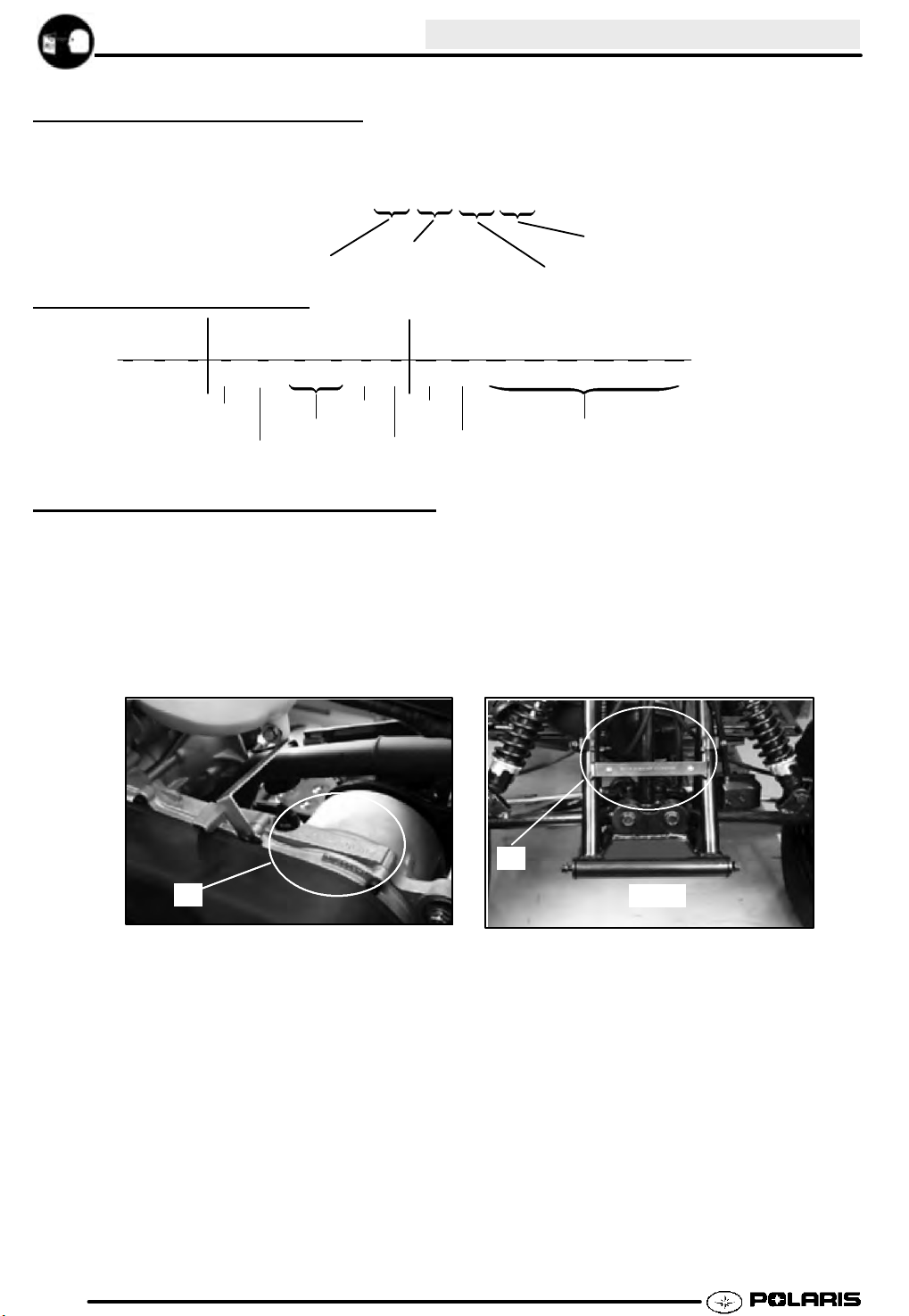
3. Reinstall the CDI and mounting strap onto the
mounting tab.
A
:
,
B
e
SPEED CONTROL SYSTEMS
Throttle Stop Speed Control System
SPEED CONTROL
Electronic Speed Control System
Your Polaris ATV is equipped with an electronic speed
control system, which controls the engine RPM and
speed of the ATV.
Speed can be adjusted by removing or installing the
jumper on the CDI (A). With the jumper installed, 50cc
models will travel no faster than 10 mph and 90cc
models will travel no faster than 15 mph. With the
jumper removed, 50cc models will travel no faster
than 15 mph and90cc models will travel no faster than
30 mph.
Jumper Removal and Installation
SYSTEMS
1. Remove the CDI and its rubber mounting strap
from the mounting tab, which is located on the
frame bulkhead near the steering post. It can be
accessed through the left front fender.
2. Remove the two screws (B) from the jumper to
remove or install the jumper. Reinstall the
screws.
Adjusting speed at the CDI is the recommended
method of speed control, but the throttle stop system
may also be used. Use the following procedure to
control how far the throttle opens.
1. Loosen the jam nut (A)
2. Turn the screw (B) inward to reduce speed or
outward to increase speed.
3. Tighten the jam nut after adjusting.
A
B
1.11
Page 16
GENERAL INFORMATION
VEHICLE INSPECTION
FRONT BRAKE
1. Each front brake has a cable connected to the right
hand brake lever.
2. Loosen the adjuster nuts at the right hand brake
lever. Turn the cable adjuster until the proper
brake setting is achieved. Tighten nuts.
REAR BRAKE
3. The rear brake is operated using the left hand brake
lever. To adjust the rear brake setting, turn the
rear brake adjuster nut until brake is set to
specification.
Rear Brake Lever Free Play:
.40-.80I (10-20 mm)
Front Brake Lever Free Play:
.40-.80I (10-20 mm)
Front Brake Lever Travel:
50 cc= 1 1/8I (28 mm)
90 cc = 1 3/4 (45 mm)
Rear Brake Lever Travel:
50 cc= 1 1/8I (28 mm)
90 cc = 2 1/2 (65 mm)
VEHICLE
INSPECTION
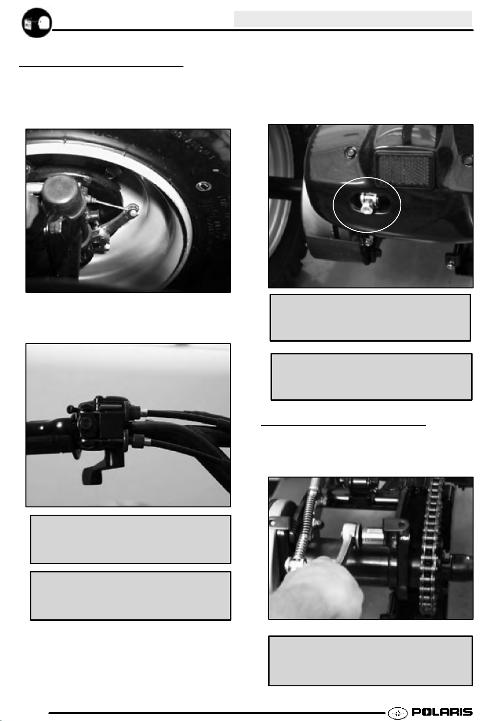
CHAIN ADJUSTMENT
1. Remove the rear cover and loosen the four bearing
housing bolts.
1.12
Chain Tension Specification:
1/4-1/2 (10-20 mm) Deflection
Page 17

GENERAL INFORMATION
2. Loosen the four bearing housing bolts. Loosen the
chain adjuster lock nut. Turn the chain adjuster
clockwise until chain is set to specification
1/4”--1/2” (6--12 mm). Tighten the chain adjuster
lock nut to specification.
Polaris Premium All Season Grease
14 oz. (PN 2871423)
Grease Gun Kit PN 2871312
Chain Adjuster Lock Nut Torque:
84 in.lbs (9.4 Nm)
3. Tighten the four bearing housing bolts to
specification. Re-install rear cover.
Bolts
Bearing Housing Bolt Torque:
43 ft.lbs (60 Nm)
LUBRICATION
1. Lubricate grease fittings on spindles monthly with
Polaris All Season Grease, or more frequently if
used often.
FRONT SHOCKS AND SPRINGS
1. Inspect the front shocks and springs to ensure
proper function. If the shock is leaking oil,
replace. The spring preload can be adjusted on
the Sportsman 90 by turning the adjuster nut.
Inspect the A-arm and weldments for any sign
damage.
REAR SHOCK AND SPRING
1. Inspect the rear shock and spring to ensure proper
function. If the shock is leaking oil, replace.
Inspect the swing arm and weldments for any sign
of damage.
1.13
Page 18

GENERAL INFORMATION
VEHICLE INSPECTION CONT’D
WHEEL NUTS
2. Inspect the front and rear wheel nuts for tightness.
Re-torque wheel nuts monthly to specification.
GFollow instructions to check /
change transmission lubricant.
Fill Plug
TRANSMISSION SPECIFICATIONS
Specified Lubricant:
Polaris Premium Synthetic Gearcase Lubricant
(PN 2871477) (Gallon) (PN 2871478) (12 oz..)
Capacity:10 fl.oz. / 300 ml.
Capacity at Change: ..... 7 oz. / 200ml
Operating Range: Oil level visible in sight
glass safe zone.
Wheel Nut Torque:
22-29ft.lbs(30-40Nm)
TRANSMISSION
LUBRICA
The transmission lubricant level should be checked
and changed in accordance with the maintenance
schedule.
Remember to:
GBe sure vehicle is level before
proceeding.
GCheck vent hose to be sure it is
routed properly and unobstructed.
TION
Drain Plug Torque:
14 ft. lbs. (19.4 Nm)
To check the level:
The gearcase fill plug (A) is located on the top of the
gearcase. The sight glass (B) is on the right-hand side
of the gearcase. The oil level must be maintained in
the safe zone of the sight glass. It should be checked
monthly and changed annually.
With the ATV on a level surface, check the oil level
through the sight glass. If the level is low, add Polaris
Premium Synthetic Gearcase Lubricant. See page
1.6 for the part numbers of Polaris-recommended
products.
A
B
1.14
Page 19

GENERAL INFORMATION
To change lubricant:
1. Place a drain pan beneath the transmission
lubricant drain plug area.
2. Remove the drain plug and wipe the magnetic end
clean to remove accumulated metallic filings.
Vent Hose
Drain Plug
Air Screw Adjustment:
50 cc: 1/2 Turn Out from Lightly Seated
90 cc: 1 Turn Out from Lightly Seated
2. Warm up the engine to operating temperature
(about 10 minutes).
3. Set idle speed to 800 RPM.
NOTE: Adjusting the air screw may affect idlespeed.
Always check throttle cable freeplay after adjusting
idle speed and adjust if necessary.
4. Turn the screw in (to richen) or out (to lean) the
mixture. Adjust air screw for best throttle
response and smooth idle.
5. Re-adjust idle speed if necessary.
3. After the lubricant has drained completely, install a
new sealing washer and install the drain plug.
Torque to 14 ft. lbs. (19.3 Nm).
4. Add the proper lubricant through the fill plug hole. Do
not overfill. An indication of over filling is lubricant
leaking from the vent hose after operation.
5. Check for leaks. Discard used lubricant properly.
THROTTLE OPERA
Check for smooth throttle opening and closing.
Throttle lever operation should be smooth and lever
must return freely without binding.
1. Start the engine and let it idle.
2. Turn handlebars from full right to full left. If idle
speed increases at any point in the turning range,
inspect throttle cable routing and condition.
3. Replace the throttle cable if worn, kinked, or
damaged.
AIR SCREW
1. Turn carburetor air screw in (clockwise) until lightly
seated. Back screw out the specified number of
turns.
ADJUSTMENT
TION
Air Screw
IDLE SPEED
1. Start engine and warm it up thoroughly.
Throttle Set Screw
2. Adjust idle speed by turning the idle adjustment
screw in (clockwise) to increase or out
(counterclockwise) to decrease RPM.
NOTE: Adjusting the idle speed affects throttle cable
freeplay and electronic throttle control (ETC)
adjustment. Always check throttle cable freeplay
after adjusting idle speed and adjust if necessary.
ADJUSTMENT
Idle Speed:
800 200 RPM
1.15
 Loading...