

Page 1

2014-2015 RZR XP 1000 / RZR XP4 1000
Service Manual
FOREWORD
The information printed within this publication includes the latest product information at time of print. The most recent
version of this Service Manual is available in electronic format at www.polarisdealers.com.
This Service Manual is designed primarily for use by certified Polaris Master Service Dealer
equipped shop and should be kept available for reference. All references to left and right side of the vehicle are from
the operator's perspective when seated in a normal riding position.
Some procedures outlined in this manual require a sound knowledge of mechanical theory, tool use, and shop
procedures in order to perform the work safely and correctly. Technicians should read the text and be familiar with the
service procedures before starting any repair. Certain procedures require the use of special tools. Use only the proper
tools as specified. If you have any doubt as to your ability to perform any of the procedures outlined in this Service
Manual, contact an authorized dealer for service.
We value your input and appreciate any assistance you can provide in helping make these publications more useful.
Please provide any feedback you may have regarding this manual. Authorized dealers can submit feedback using 'Ask
Polaris'. Click on 'Ask Polaris', and then click on 'Service Manual / Service Literature Question'.
Consumers, please provide your feedback in writing to: Polaris Industries Inc. ATTN: Service Publications Department,
2100 Hwy 55, Medina, MN 55340.
Publication Printed August 2014 (PN 9925724 R01)
®
technicians in a properly
© Copyright 2014 Polaris Industries Inc. All information contained within this publication is based on the latest product information at the time of publication. Due to
constant improvements in the design and quality of production components, some minor discrepancies may result between the actual vehicle and the information
presented in this publication. Depictions and/or procedures in this publication are intended for reference use only. No liability can be accepted for omissions or
inaccuracies. Any reprinting or reuse of the depictions and/or procedures contained within, whether whole or in part, is expressly prohibited. Printed in U.S.A.
Page 2

UNDERSTANDING SAFETY LABELS AND DIRECTIONS
Throughout this manual, important information is brought to your attention by the following symbols:
WARNING
SAFETY ALERT WARNING indicates a potential hazard that may result in severe injury or death to the operator,
bystander or person(s) inspecting or servicing the vehicle.
CAUTION
SAFETY ALERT CAUTION indicates a potential hazard that may result in minor personal injury or damage to the
vehicle.
CAUTION
CAUTION indicates special precautions that must be taken to avoid vehicle damage or property damage.
NOTE:
NOTE provides key information by clarifying instructions.
IMPORTANT:
IMPORTANT provides key reminders during disassembly, assembly and inspection of components.
Page 3

TRADEMARKS
POLARIS ACKNOWLEDGES THE FOLLOWING PRODUCTS MENTIONED IN THIS MANUAL:
Loctite, Registered Trademark of the Loctite Corporation
Nyogel, Trademark of Wm. F. Nye Co.
Fluke, Registered Trademark of John Fluke Mfg. Co.
Mity-Vac, Registered Trademark of Neward Enterprises, Inc.
Torx, Registered Trademark of Textron
Hilliard, Trademark of the Hilliard Corporation
Warn, Trademark of Warn Industries
FOX, Registered Trademark of FOX RACING SHOX
RydeFX, Registered Trademark of ArvinMeritor
Some Polaris factory publications can be downloaded from www.polarisindustries.com, purchased from
www.purepolaris.com or by contacting the nearest Polaris dealer.
Page 4

Page 5

GENERAL INFORMATION
1
MAINTENANCE
ENGINE / COOLING SYSTEM
FUEL SYSTEM
PVT SYSTEM
TRANSMISSION
FINAL DRIVE
STEERING / SUSPENSION
BRAKE SYSTEM
BODY / FRAME
2
3
4
5
6
7
8
9
10
ELECTRICAL
11
Page 6

Page 7

GENERAL INFORMATION
CHAPTER 1
GENERAL INFORMATION
VEHICLE IDENTIFICATION . . . . . . . . . . . . . . . . . . . . . . .. . . . . . . . . .. . . . . . . . . .. . . . . . . . . .. . . . . . . . . . . . . . . . . . . . . . . . . 1.2
MODEL NUMBER DESIGNATION. . . .. . . . . . . . . .. . . . . . . . . . . . . . . . . . . . . . . . . . . . . . . . . . . . . . . . . . . . . .. . . . . . 1.2
MODEL NUMBER DESIGNATION. . . .. . . . . . . . . .. . . . . . . . . . . . . . . . . . . . . . . . . . . . . . . . . . . . . . . . . . . . . .. . . . . . 1.2
VEHICLE IDENTIFICATION NUMBER.. . . . . . . . . . . . . . . .. . . . .. . . . .. . . . . . . . . .. . . . . . . . . . . . . . . . . . . . . . . . . 1.3
VEHICLE IDENTIFICATION NUMBER (VIN) DESIGNATION (2015+). .. . . . .. . . . . . . . . . . . . . . . . . . . . . . . . 1.3
VEHICLE AND ENGINE SERIAL NUMBER LOCATION . . .. . . . . . . . . .. . . . . . . . . . . . . . . . . . . . . . . . . . . . . . . . 1.4
VEHICLE INFORMATION . . . . . . . . . . . . . . . . . . . . . . . . . . . . . . . . .. . . . . . . . . .. . . . . . . . . .. . . . . . . . . .. . . . . . . . . . . . . . . . . 1.5
REPLACEMENT KEYS . . . . . . . . . . . . . . . . . . . . . . . . . . . . .. . . . . . . . . .. . . . . . . . . .. . . . . . . . . .. . . . . . . . . . . . . . . . . 1.5
PUBLICATION NUMBERS . . . .. . . . . . . . . .. . . . . . . . . .. . . . . . . . . . . . . . . . . . . . . . . . . . . . . . . . . . . . . . . . . . . . . . . . . 1.5
SPECIAL TOOLS . . . . . . . . . . . . . . . . . . . . . . . . . . . . . . . . . . . . . . . . . . . . . . . . . . . . . . . . . . . . .. . . . .. . . . .. . . . . . . . . . . 1.6
GENERAL SPECIFICATIONS. . . . . . .. . . . . . . . . .. . . . . . . . . .. . . . . . . . . . . . . . . . . . . . . . . . . . . . . . . . . . . . . . . . . . . . . .. .1.10
2014-2015 RZR XP 1000 / EPS. . . . . . . .. . . . . . . . . .. . . . . . . . . .. . . . . . . . . . . . . . . . . . . . . . . . . . . . . . . . . . . . . . . .1.10
RZR XP 1000 CLUTCH CHART . . . . . . . . . . . . . . . . . . . . . . . . . . . .. . . . . . . . . .. . . . .. . . . .. . . . . . . . . . . . . . . . . . . 1.11
2014-2015 RZR XP 4 1000 . . . . . . . . . . . . . . . . . . . . . .. . . . . . . . . .. . . . . . . . . .. . . . . . . . . .. . . . . . . . . . . . . . . . . . . .1.13
2014-2015 RZR 1000 XP4. . . . . . . . . . . . . . . . . . . . . . . . . . . . . . . . . . . . . . . . . . . . . . . . . . . . . . . . . . . .. . . . .. . . . .. . .1.14
2015 RZR XP 1000 EPS HIGH LIFTER . . . . . . . . . .. . . . . . . . . .. . . . . . . . . .. . . . . . . . . .. . . . . . . . . . . . . . . . . . . .1.16
2015 RZR XP 1000 HIGH LIFTER . . . . . . . . . . . . . . . . . . . . . . . . . . . . . . . . . . . . . . . . . .. . . . . . . . . .. . . . . . . . . .. . .1.18
2015 RZR XP 1000 DESERT EDITION . . . . . . . . . . . . . . . . . . . . . . . . . . . . . . . . .. . . . .. . . . .. . . . . . . . . . . . . . . . .1.18
2015 RZR XP 1000 DESERT EDITION CLUTCH CHART .. . . . .. . . . .. . . . . . . . . . . . . . . . . . . . . . . . . . . . . . .1.20
MISC. SPECIFICATIONS AND CHARTS . . . . . . . . . . . . . . . . . . . . . . . .. . . . . . . . . .. . . . .. . . . .. . . . . . . . . .. . . . . . . . .1.21
MASTER TORQUE TABLE... . . . . .. . . . . . . . . .. . . . . . . . . . . . . . . . . . . . . . . . . . . . . . . . . . . . . . . . . . . . . .. . . . . . . .1.21
CONVERSION TABLE . . . .. . . . . . . . . .. . . . . . . . . . . . . . . . . . . . . . . . . . . . . . . . . . . . . . . . . . . . . .. . . . . . . . . .. . . . . .1.23
STANDARD BOLT TORQUE SPECIFICATION.... . . . . . . . . .. . . . . . . . . . . . . . . . . . . . . . . . . . . . . . . . . . . . . . . .1.24
METRIC BOLT TORQUE SPECIFICATION . . . . .. . . . .. . . . .. . . . . . . . . .. . . . . . . . . . . . . . . . . . . . . . . . . . . . . . .1.24
SAE TAP / DRILL SIZES . . . . . . . . . . . . . . . . . . . . . . . . . . . . . . . . . . . . . . . . . . . . . . . . . . . . . . .. . . . . . . . . .. . . . . . . . .1.25
METRIC TAP / DRILL SIZES . . .. . . . . . . . . .. . . . . . . . . .. . . . . . . . . . . . . . . . . . . . . . . . . . . . . . . . . . . . . . . . . . . . . ..1.25
DECIMAL EQUIVALENTS.... . . . .. . . . . . . . . . . . . . . . . . . . . . . . . . . . . . . . . . . . . . . . . . . . . .. . . . . . . . . .. . . . . . . . .1.26
1
9925724 R01 - 2014-2015 RZR XP 1000 / RZR XP4 1000 Service Manual
© Copyright 2014 Polaris Industries Inc.
1.1
Page 8

GENERAL INFORMATION
VEHICLE IDENTIFICATION
Model Number Designation
Example: Z14ST1EAL
GROUP
1st digit
Z = RZR
* = digits that would transfer to 17 digit VIN and are used in digits 4-8 respectively
** = 9th digit will be used on color/featured versions of models (not including the base)
First 3 digits and 9th digit are used in model number only. They are not used with the 17 digit VIN.
MODEL
YEAR
2/3rd
digit
11
12
13
14
15
CHASSIS DRIVELINE ENGINE CATEGORY OPTION REGION
4th digit* 5th digit* 6th digit* 7th digit* 8th digit 9th digit** 10th digit
J = RZR XP
V = RZR
X = Multi-
pass RZR
E = 4x4 Shaft / IRS
H = 4x4 Shaft / IRS
T = 4x4 Shaft /
Trailing Arm
Displacement in cc
divided by 10 and
rounded to two digits
(i.e. 50 = 498cc)
- - OR - 6 = 570
7 = 760
9 = 875
E = EPS
F = D + E
A = ORV
E = EU On-road
F = INT’L
M = Military
S =
Scandinavian
V = EU On-road
C = Calif.
Model Number Designation
Example: A15SEA57AD
GROUP MODEL YEAR MAKE / CHASSIS CODE ENGINE CODE REGION OPTION
1st 2nd 3rd 4th* 5th* 6th* 7th* 8th* 9th 10th**
A 1
5
S E A
5
7
A D
* = digits that would transfer to 17 digit VIN and are used in digits 4-8 respectively
** = 10th digit will be used on color/featured versions of models (not including the base)
First 3 digits and 10th digit are used in model number only. They are not used with the 17 digit VIN.
Digits 1 through 8 determine Digital Wrench calibration.
1.2
9925724 R01 - 2014-2015 RZR XP 1000 / RZR XP4 1000 Service Manual
© Copyright 2014 Polaris Industries Inc.
Page 9

Vehicle Identification Number
Example: 4XAKA09A0F3000000
VEHICLE DESCRIPTORS VEHICLE IDENTIFIERS
GENERAL INFORMATION
1
WORLD MFG. ID
CHASSIS
DRIVELINE
1 2 3 4
4 X A K A 0 9 A 0 F 3 0 0 0 0 0 0
* Model Year: A = 2010; B = 2011; C = 2012; D = 2013; E = 2014; F = 2015
5 6 7 8 9 10 11 12 13 14 15 16 17
ENGINE SIZE
ENGINE
MODIFIER
CATEGORY
CHECK DIGIT
MODEL YEAR *
MFG. LOCATION
INDIVIDUAL SERIAL NO.
Vehicle Identification Number (VIN) Designation (2015+)
Example: 4XARH57A0F3000000
VEHICLE DESCRIPTORS VEHICLE IDENTIFIERS
WORLD MFG. ID
CHASSIS
DRIVELINE
1 2 3 4 5 6 7 8 9 10 11 12 13 14 15 16 17
4 X A R H 5 7 A 0 F 3 0 0 0 0 0 0
* Model Year: A = 2010; B = 2011; C = 2012; D = 2013; E = 2014; F = 2015
ENGINE SIZE
ENGINE MODIFIER
CATEGORY
CHECK DIGIT
MODEL YEAR *
MFG. LOCATION
INDIVIDUAL SERIAL NO.
9925724 R01 - 2014-2015 RZR XP 1000 / RZR XP4 1000 Service Manual
© Copyright 2014 Polaris Industries Inc.
1.3
Page 10

GENERAL INFORMATION
Vehicle and Engine Serial Number Location
Whenever corresponding about a Polaris ORV, refer to the vehicle identification number (VIN) and the engine serial
number.
The VIN can be found stamped on a portion of the left rear frame, behind the lower shock mounting location. Refer to
Figure 1-1.
The engine serial number can be found on a decal applied to the front of the engine crankcase (A) or stamped into the
crankcase on the PTO side of the engine (B). Refer to Figure 1-2.
1.4
9925724 R01 - 2014-2015 RZR XP 1000 / RZR XP4 1000 Service Manual
© Copyright 2014 Polaris Industries Inc.
Page 11

VEHICLE INFORMATION
GENERAL INFORMATION
Replacement Keys
Replacement keys can be made from the original key. To identify which series the key is, take the first two digits on the
original key and refer to the chart to the right for the proper part number.
SERIES# PART NUMBER
20 4010278
21 4010278
22
23 4010321
27 4010321
28 4010321
31 4110141
32 4110148
67 4010278
68 4010278
4010321
1
Publication Numbers
MODEL OWNER’S MANUAL PARTS MANUAL
2014 RZR XP 1000 9924687 9924688
2014 RZR XP 1000 EPS 9924687 9924688
2014 RZR XP 1000 INT’L 9924687 9924688
2014 RZR XP 4 1000 9924687 9924688
2015 RZR XP 1000 EPS 9925838 9925754
2015 RZR XP 1000 INT’L 9925838 9925858
2015 RZR XP4 1000 9925838 9925795
2015 RZR XP 1000 EPS High Lifter
NOTE: When ordering service parts be sure to use the correct parts manual.
Polaris factory publications can be found at www.polaris.com or purchased from www.purepolaris.com.
9925836 9925754
9925724 R01 - 2014-2015 RZR XP 1000 / RZR XP4 1000 Service Manual
© Copyright 2014 Polaris Industries Inc.
1.5
Page 12

GENERAL INFORMATION
SPECIAL TOOLS
Special tools may be required while servicing this vehicle. Some of the tools listed or depicted are mandatory, while
other tools may be substituted with a similar tool, if available. Polaris recommends the use of Polaris Special Tools
when servicing any Polaris product. Dealers may order special tools through Polaris’ official tool supplier.
Bosch Automotive Service Solutions:
1-800-345-2233 or http://polaris.service-solutions.com/
1.6
9925724 R01 - 2014-2015 RZR XP 1000 / RZR XP4 1000 Service Manual
© Copyright 2014 Polaris Industries Inc.
Page 13

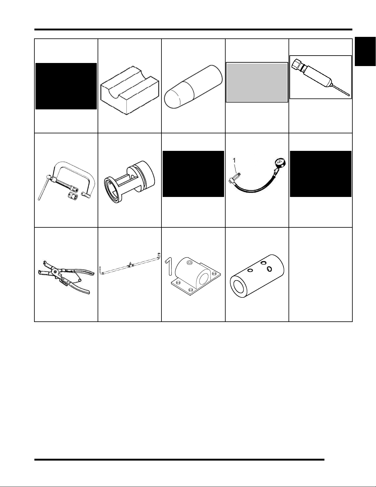
GENERAL INFORMATION
2200421
Gas Shock
Recharging Kit
2870910-A
Roller Pin Tool
2460761
Hall Sensor Probe
Harness
2870975
Mity-Vac Pressure
Test Tool
2870341-A
Drive Clutch Spider
Remover/Installer
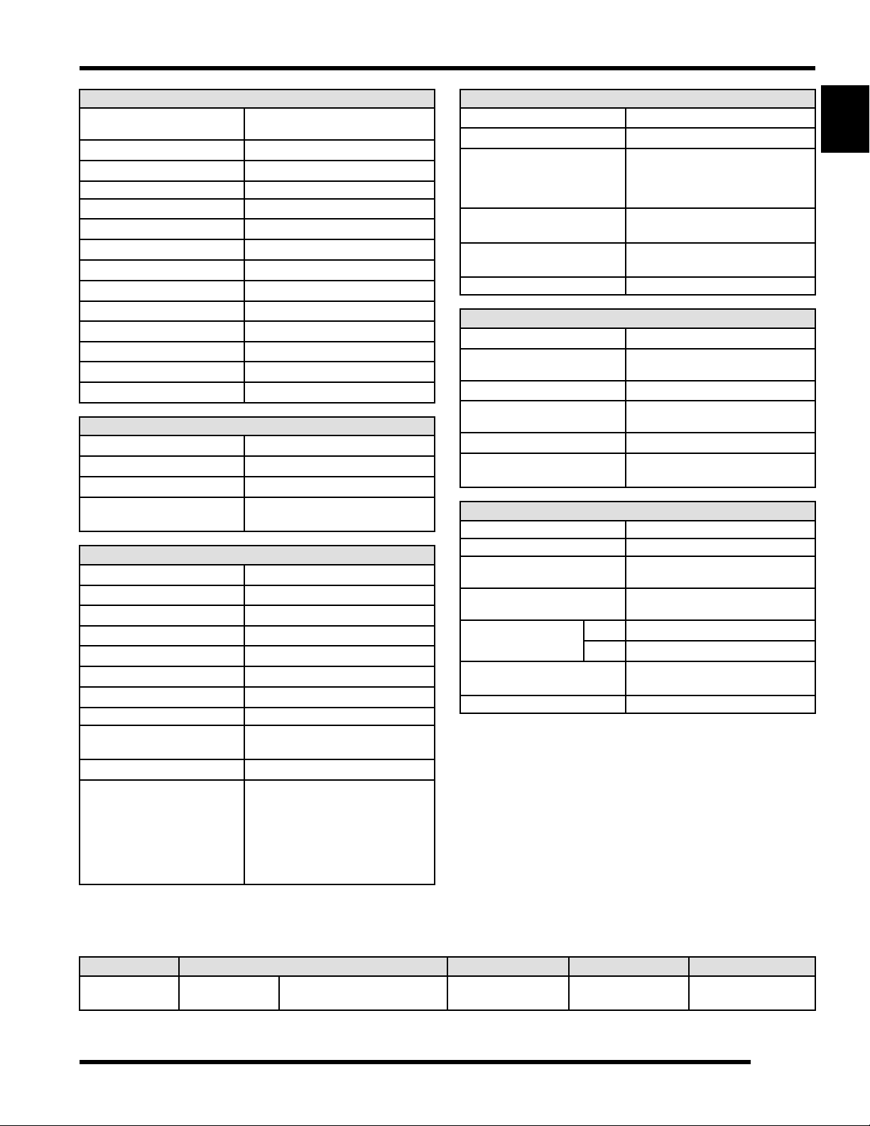
2871056
Driven Clutch Puller
2870386
Piston Pin Puller
2871226
Clutch Bushing
Replacement Tool Kit
2870630
Timing Light
2871282
Transmission Seal
Driver (50 MM)
1
2871351
IFP Depth Tool
2872608
Roll Pin Removal Tool
(27″)
2871358-B
Drive Clutch Holding
Fixture
2876389
Combination Pliers
2871702
Shaft Drive
Transmission and
Front Gearcase Tool
Kit
2877408
Spanner Wrench /
Clutch Spreader
2871745
Static Timing Light
Harness
8700226
CV Boot Clamp Pliers
(ear)
2872085
Drive Clutch Puller
9314177-A
Drive Clutch Holding
Tool
9925724 R01 - 2014-2015 RZR XP 1000 / RZR XP4 1000 Service Manual
© Copyright 2014 Polaris Industries Inc.
1.7
Page 14

GENERAL INFORMATION
PA-49316
Water Pump Drive &
Rotor Removal Tool
PU-47471
Smartlink Module Kit
PA-50231
Snorkel Driver
PU-48951
CV Boot Clamp Pliers
(Stepless)
PS-45908
T-Handle Tool
PU-49466
Relay Bypass
PU-43506-A
Fuel Pressure Gauge
Kit
PU-50105
Oil Filter Wrench
PU-45281–A
Shock Body Holding
Tool
PU-50296
Battery Tester
PU-50338
Hydrometer
PU-50565
Oil Pressure Gauge
Adapter (1/2 NPT)
PU-50518
Clutch Compressor
PU-50566
Transmission Nut
Socket
PU-50562
Engine Stand Adapter
PU-50578
Clutch Spider Nut
Socket
PU-50563
Cylinder Holding &
Camshaft Timing
Plate
PU-50624
Rolling Engine Stand
PU-50564
Water Pump Seal
Installer
PU-50625
Engine Stand Adapter
Sleeve (2″)
1.8
9925724 R01 - 2014-2015 RZR XP 1000 / RZR XP4 1000 Service Manual
© Copyright 2014 Polaris Industries Inc.
Page 15
GENERAL INFORMATION
PU-50658
Clutch Center
Distance Tool
PV-1253
Valve Spring
Compressor
PU-50931
Shock Rod Holding
Tool (3/4″)
PV-43513-A
Valve Spring
Compressor Adapter
PU-50939
Shock Seal Protector
Sleeve (5/8″)
PV-43526
Connector Test Kit
PU-51024
Shock Rod Holding
Tool
PV-43531
Oil Presure gauge
PU-51039
Gas Shock Fill Tool
PV-43568
Fluke Multimeter
1
PV-43570
Piston Ring
Compressor Pliers
PV-48656
Fuel Pressure Gauge
Adapter
PW-47053
Bench Mount Engine
Stand
PW-47054
Engine Stand Adapter
Sleeve (2 3/8″)
9925724 R01 - 2014-2015 RZR XP 1000 / RZR XP4 1000 Service Manual
© Copyright 2014 Polaris Industries Inc.
1.9
Page 16

GENERAL INFORMATION
GENERAL SPECIFICATIONS
2014-2015 RZR XP 1000 / EPS
CATEGORY DIMENSION / CAPACITY
Length
Width 64″ / 162.5 cm
Height
Wheel Base 90″ / 228.6 cm
Ground Clearance 13.5″ / 34.3 cm
Dry Weight 1379 lbs. / 625.5 kg
Gross Vehicle Weight 2200 lbs. / 998 kg
Cargo Box Capacity 300 lbs. / 136 kg
119″ / 302.2 cm
73.75″ / 187.3 cm
Maximum Weight Capacity (Payload)
Hitch Towing Capacity
Hitch Tongue Capacity
740 lbs. / 335.6 kg
(Includes riders, cargo and
accessories)
This vehicle is not equipped with
a hitch for towing loads. Do not
use this vehicle for towing. Do not
modify the vehicle by adding a
hitch.
1.10
9925724 R01 - 2014-2015 RZR XP 1000 / RZR XP4 1000 Service Manual
© Copyright 2014 Polaris Industries Inc.
Page 17
GENERAL INFORMATION
ENGINE
Platform
Engine Displacement
Number of Cylinders
Bore & Stroke 93 x 73.5 mm
Compression Ratio
Engine Idle Speed
Engine Max Speed
Valve Clearance (Intake) 0.005-0.007″ (0.125-0.175 mm)
Valve Clearance (Exhaust) 0.009-0.011″ (0.229-0.275 mm)
Engine Hot Light
Lubrication
Oil Requirements
Oil Capacity 2.5 qts. (2.4 L)
Coolant Capacity 5.44 qt (5.1 L)
Domestic Twin Cyl., 4–Stroke,
DOHC
999cc
2
11:1
1200 +/- 100 RPM
8800 RPM
Instrument Cluster Indicator
Wet Sump
PS4
FUEL SYSTEM
Type Bosch ME17 EFI
Fuel Delivery Electronic Fuel Pump (in-tank)
Fuel Pressure 58 ± 2 PSI (400 ± 14 kPa)
Fuel Capacity /
Requirement
9.5 gal. (36 L)
87 Octane (minimum)
ELECTRICAL
Alternator Max Output 560 Watts @ 3000 RPM
Lights: Main Headlights Dual Beam LED cluster
Taillights 0.2 Watt LED cluster
Brake Lights 2.9 Watt LED cluster
Ignition System ME17 ECU
Spark Plug / Gap XG4YCX / 0.7–0.8 mm
Battery / Amp Hr 12v Flooded, 575 CCA
DC Outlet Standard 12 Volt
Relays Fan, EFI, Fuel Pump, Chassis,
Circuit Breaker 20A Cooling Fan
Fuses 20A EFI
EPS (if appl.)
10A Fuel Pump
5A Brake Light
20A Accessory
10A Drive
10A Lights
20A EPS (if appl.)
DRIVETRAIN
Transmission Type
Shift Type
Transmission Gear Ratios:
High
Low
Reverse
Front Gearcase Lubricant
Requirement
Transmission Lubricant
Requirement
Drive Belt 3211148
Polaris Automatic PVT
In Line Shift - P/ H / L / N / R
10.73:1
22.79:1
20.41:1
Demand Drive
8.5 oz. (250 ml)
Full Synthetic AGL
44 oz. (1300 ml)
STEERING / SUSPENSION
Toe Out 1/8 - 3/16″ (3.2 - 4.8 mm)
Front Suspension Independent Dual A-arm
Front Travel 16″ (40.6 cm)
Rear Suspension Independent Trailing Arm
Rear Travel 18″ (45.7 cm)
Spring Adjustment Threaded Spanner Wrench
Walker Evans™ 2.0″
Walker Evans™ 2.5″
Adjustment
WHEELS / BRAKES
Front Rim / Size Aluminum 14 x 6
Rear Rim / Size Aluminum 14 x 8
Front Tire Make / Model /
Size
Rear Tire Make / Model /
Size
Tire Air Pressure
Brake System
Front & Rear
Brake Fluid DOT 4
Maxxis Bighorn
29 x 9 R14
Maxxis Bighorn
29 x 11 R14
Front 16 psi (110 kPa)
Rear 16 psi (110 kPa)
Foot Actuated 4 Wheel
Hydraulic – Dual Bore Caliper
1
RZR XP 1000 CLUTCH CHART
MODEL ALTITUDE SHIFT WEIGHT DRIVE SPRING DRIVEN SPRING
2014 XP 1000
Meters
(Feet)
0-1800
(0-6000)
26-61
(1323098)
White / Orange
(7043924)
Red
(3234452)
1.11
9925724 R01 - 2014-2015 RZR XP 1000 / RZR XP4 1000 Service Manual
© Copyright 2014 Polaris Industries Inc.
Page 18

GENERAL INFORMATION
MODEL ALTITUDE SHIFT WEIGHT DRIVE SPRING DRIVEN SPRING
2015 XP 1000
Meters
(Feet)
1800-3700
(6000 - 12000)
0-1800
(0-6000)
1800-3700
(6000-12000)
26-55
(1322982)
26-63
(1323176)
26-59
(1322981)
White / Orange
(7043924)
Orange / Black
(1323176)
Orange / Black
(7044338)
Red
(3234452)
Red
(3234452)
Red
(3234452)
1.12
9925724 R01 - 2014-2015 RZR XP 1000 / RZR XP4 1000 Service Manual
© Copyright 2014 Polaris Industries Inc.
Page 19

2014-2015 RZR XP 4 1000
CATEGORY DIMENSION / CAPACITY
Length
Width 64″ / 162.5 cm
Height
Wheel Base 117″ / 297.2 cm
Ground Clearance 13.5″ / 34.3 cm
Dry Weight 1596 lbs. / 724 kg
Gross Vehicle Weight 2560 lbs. / 1161 kg
Cargo Box Capacity 300 lbs. / 136 kg
146″ / 370.8 cm
73.75″ / 187.3 cm
GENERAL INFORMATION
1
Maximum Weight Capacity (Payload)
Hitch Towing Capacity This vehicle is not equipped with
Hitch Tongue Capacity
900 lbs. / 408 kg
(Includes riders, cargo and
accessories)
a hitch for towing loads. Do not
use this vehicle for towing. Do not
modify the vehicle by adding a
hitch.
9925724 R01 - 2014-2015 RZR XP 1000 / RZR XP4 1000 Service Manual
© Copyright 2014 Polaris Industries Inc.
1.13
Page 20

GENERAL INFORMATION
ENGINE
Platform
Engine Displacement
Number of Cylinders
Bore & Stroke 93 x 73.5 mm
Compression Ratio
Engine Idle Speed
Engine Max Speed
Valve Clearance (Intake) 0.005-0.007″ (0.125-0.175 mm)
Valve Clearance (Exhaust) 0.009-0.011″ (0.229-0.275 mm)
Engine Hot Light
Lubrication
Oil Requirements
Oil Capacity 2.5 qts. (2.4 L)
Coolant Capacity 6.08 qt (5.75 L)
Domestic Twin Cyl., 4–Stroke,
DOHC
999cc
2
11:1
1200 +/- 100 RPM
8800 RPM
Instrument Cluster Indicator
Wet Sump
PS4
FUEL SYSTEM
Type Bosch ME17 EFI
Fuel Delivery Electronic Fuel Pump (in-tank)
Fuel Pressure 58 ± 2 PSI (400 ± 14 kPa)
Fuel Capacity /
Requirement
9.5 gal. (36 L)
87 Octane (minimum)
ELECTRICAL
Alternator Max Output 560 Watts @ 3000 RPM
Lights: Main Headlights Dual Beam LED cluster
Taillights 0.2 Watt LED cluster
Brake Lights 2.9 Watt LED cluster
Ignition System ME17 ECU
Spark Plug / Gap XG4YCX / 0.7–0.8 mm
Battery / Amp Hr 12v Flooded, 575 CCA
DC Outlet Standard 12 Volt
Relays Fan, EFI, Fuel Pump, Chassis,
Circuit Breaker 20A Cooling Fan
Fuses 20A EFI
EPS (if appl.)
10A Fuel Pump
5A Brake Light
20A Accessory
10A Drive
10A Lights
20A EPS (if appl.)
DRIVETRAIN
Transmission Type
Shift Type
Transmission Gear Ratios:
High
Low
Reverse
Front Gearcase Lubricant
Requirement
Transmission Lubricant
Requirement
Drive Belt 3211148
Polaris Automatic PVT
In Line Shift - P/ H / L / N / R
12.05:1
25.59:1
22.92:1
Demand Drive
8.5 oz. (250 ml)
Full Synthetic AGL
44 oz. (1300 ml)
STEERING / SUSPENSION
Toe Out 1/8 - 3/16″ (3.2 - 4.8 mm)
Front Suspension Independent Dual A-arm
Front Travel 16″ (40.6 cm)
Rear Suspension Independent Trailing Arm
Rear Travel 18″ (45.7 cm)
Spring Adjustment Threaded Spanner Wrench
Walker Evans™ 2.0″
Walker Evans™ 2.5″
Adjustment
WHEELS / BRAKES
Front Rim / Size Aluminum 14 x 6
Rear Rim / Size Aluminum 14 x 8
Front Tire Make / Model /
Size
Rear Tire Make / Model /
Size
Tire Air Pressure
Brake System
Front & Rear
Brake Fluid DOT 4
Maxxis Bighorn
29 x 9 R14
Maxxis Bighorn
29 x 11 R14
Front 19 psi (131 kPa)
Rear 21 psi (145 kPa)
Foot Actuated 4 Wheel
Hydraulic – Dual Bore Caliper
2014-2015 RZR 1000 XP4
MODEL ALTITUDE SHIFT WEIGHT DRIVE SPRING DRIVEN SPRING
2014 XP4 1000
Meters
(Feet)
0-1800
(0-6000)
26-67
(1323177)
White / Orange
(7043924)
Red
(3234452)
1.14
9925724 R01 - 2014-2015 RZR XP 1000 / RZR XP4 1000 Service Manual
© Copyright 2014 Polaris Industries Inc.
Page 21

GENERAL INFORMATION
MODEL ALTITUDE SHIFT WEIGHT DRIVE SPRING DRIVEN SPRING
2015 XP4 1000
Meters
(Feet)
1800-3700
(6000 - 12000)
0-1800
(0-6000)
1800-3700
(6000 - 12000)
26-61
(1323098)
26-65
(1323260
26-59
(1322981)
White / Orange
(7043924)
White / Orange
(7043924)
White / Orange
(7043924)
Red
(3234452)
Red
(3234452)
Red
(3234452)
1
9925724 R01 - 2014-2015 RZR XP 1000 / RZR XP4 1000 Service Manual
© Copyright 2014 Polaris Industries Inc.
1.15
Page 22

GENERAL INFORMATION
2015 RZR XP 1000 EPS High Lifter
CATEGORY DIMENSION / CAPACITY
Length
Width 66″ / 167.6 cm
Height
Wheel Base 90″ / 228.6 cm
Ground Clearance 14.25″ / 36.2 cm
Dry Weight 1545 lbs. / 701 kg
Gross Vehicle Weight 2470 lbs. / 1120 kg
Cargo Box Capacity 300 lbs. / 136 kg
122″ / 310 cm
74.5″ / 189.2 cm
Maximum Weight Capacity (Payload)
Hitch Towing Capacity The tow loop on the rear of the
Hitch Tongue Capacity
740 lbs. / 335.6 kg
(Includes riders, cargo and
accessories)
vehicle is provided for recovery
use ONLY. Tow a vehicle ONLY of
equal or lesser size and weight.
When towing a disabled RZR
vehicle, place the disabled
vehicle’s transmission in neutral.
Do not operate the vehicle faster
than 10 MPH (16 km/h) when
towing.
1.16
9925724 R01 - 2014-2015 RZR XP 1000 / RZR XP4 1000 Service Manual
© Copyright 2014 Polaris Industries Inc.
Page 23

GENERAL INFORMATION
ENGINE
Platform
Engine Displacement
Number of Cylinders
Bore & Stroke 93 x 73.5 mm
Compression Ratio
Engine Idle Speed
Engine Max Speed
Valve Clearance (Intake) 0.005-0.007″ (0.125-0.175 mm)
Valve Clearance (Exhaust) 0.009-0.011″ (0.229-0.275 mm)
Engine Hot Light
Lubrication
Oil Requirements
Oil Capacity 2.5 qts. (2.4 L)
Coolant Capacity 5.44 qt (5.1 L)
Domestic Twin Cyl., 4–Stroke,
DOHC
999cc
2
11:1
1200 +/- 100 RPM
8800 RPM
Instrument Cluster Indicator
Wet Sump
PS-4 5W-50 4-Cycle Oil and
PS-4 Extreme Duty 10W-50 4Cycle Oil
FUEL SYSTEM
Type Bosch ME17 EFI
Fuel Delivery Electronic Fuel Pump (in-tank)
Fuel Pressure 58 ± 2 PSI (400 ± 14 kPa)
Fuel Capacity /
Requirement
9.5 gal. (36 L)
87 Octane (minimum)
ELECTRICAL
Alternator Max Output 560 Watts @ 3000 RPM
Lights: Main Headlights Dual Beam LED cluster
Taillights 0.2 Watt LED cluster
Brake Lights 2.9 Watt LED cluster
Ignition System ME17 ECU
Spark Plug / Gap XG4YCX / 0.7–0.8 mm
Battery / Amp Hr 12v Flooded, 575 CCA
DC Outlet Standard 12 Volt
Relays Fan, EFI, Fuel Pump, Chassis,
Circuit Breaker 20A Cooling Fan
Fuses 10A EFI
EPS (if appl.)
10A Fuel Pump
5A Brake Light
10A Accessory
10A Drive
10A Lights
20A EPS (if appl.)
DRIVETRAIN
Transmission Type
Shift Type
Transmission Gear Ratios:
High
Low
Reverse
Front Gearcase Lubricant
Requirement
Transmission Lubricant
Requirement
Drive Belt 3211148
Polaris Automatic PVT
In Line Shift - P/ H / L / N / R
12.05:1
25.59:1
22.92:1
Demand Drive
8.5 oz. (250 ml)
Full Synthetic AGL
44 oz. (1300 ml)
STEERING / SUSPENSION
Toe Out 1/8 - 3/16″ (3.2 - 4.8 mm)
Front Suspension Independent Dual A-arm
Front Travel 16″ (40.6 cm)
Rear Suspension Independent Trailing Arm
Rear Travel 18″ (45.7 cm)
Spring Adjustment Threaded Spanner Wrench
Walker Evans™ 2.0″
Walker Evans™ 2.5″
Adjustment
WHEELS / BRAKES
Front Rim / Size Aluminum 14 x 6
Rear Rim / Size Aluminum 14 x 6
Front Tire Make / Model /
Size
Rear Tire Make / Model /
Size
Tire Air Pressure
Brake System
Front & Rear
Brake Fluid DOT 4
High Lifter Outlaw
29.5 x 9.5 R14
High Lifter Outlaw
29.5 x 9.5 R14
Front 18 psi (124 kPa)
Rear 18 psi (124 kPa)
Foot Actuated 4 Wheel
Hydraulic – Dual Bore Caliper
2
2
1
9925724 R01 - 2014-2015 RZR XP 1000 / RZR XP4 1000 Service Manual
© Copyright 2014 Polaris Industries Inc.
1.17
Page 24

GENERAL INFORMATION
2015 RZR XP 1000 High Lifter
MODEL ALTITUDE SHIFT WEIGHT DRIVE SPRING DRIVEN SPRING
High Lifter
Edition
Meters
(Feet)
0-1800
(0-6000)
2015 RZR XP 1000 Desert Edition
26-61
(1323260)
White / Orange
(7043924)
Red
(3234452)
1.18
9925724 R01 - 2014-2015 RZR XP 1000 / RZR XP4 1000 Service Manual
© Copyright 2014 Polaris Industries Inc.
Page 25

CATEGORY DIMENSION / CAPACITY
Length
Width 64″ / 162.5 cm
Height
Wheel Base 90″ / 228.6 cm
Ground Clearance 13.5″ / 34.3 cm
Dry Weight 1379 lbs. / 625.5 kg
Gross Vehicle Weight 2200 lbs. / 998 kg
Cargo Box Capacity 300 lbs. / 136 kg
119″ / 302.2 cm
73.75″ / 187.3 cm
GENERAL INFORMATION
1
Maximum Weight Capacity (Payload)
Hitch Towing Capacity This vehicle is not equipped with
Hitch Tongue Capacity
740 lbs. / 335.6 kg
(Includes riders, cargo and
accessories)
a hitch for towing loads. Do not
use this vehicle for towing. Do not
modify the vehicle by adding a
hitch.
9925724 R01 - 2014-2015 RZR XP 1000 / RZR XP4 1000 Service Manual
© Copyright 2014 Polaris Industries Inc.
1.19
Page 26

GENERAL INFORMATION
ENGINE
Platform
Engine Displacement
Number of Cylinders
Bore & Stroke 93 x 73.5 mm
Compression Ratio
Engine Idle Speed
Engine Max Speed
Valve Clearance (Intake) 0.005-0.007″ (0.125-0.175 mm)
Valve Clearance (Exhaust) 0.009-0.011″ (0.229-0.275 mm)
Engine Hot Light
Lubrication
Oil Requirements
Oil Capacity 2.5 qts. (2.4 L)
Coolant Capacity 5.44 qt (5.1 L)
Domestic Twin Cyl., 4–Stroke,
DOHC
999cc
2
11:1
1200 +/- 100 RPM
8800 RPM
Instrument Cluster Indicator
Wet Sump
PS4
FUEL SYSTEM
Type Bosch ME17 EFI
Fuel Delivery Electronic Fuel Pump (in-tank)
Fuel Pressure 58 ± 2 PSI (400 ± 14 kPa)
Fuel Capacity /
Requirement
9.5 gal. (36 L)
87 Octane (minimum)
ELECTRICAL
Alternator Max Output 560 Watts @ 3000 RPM
Lights: Main Headlights Dual Beam LED cluster
Taillights 0.2 Watt LED cluster
Brake Lights 2.9 Watt LED cluster
Ignition System ME17 ECU
Spark Plug / Gap XG4YCX / 0.7–0.8 mm
Battery / Amp Hr 12v Flooded, 575 CCA
DC Outlet Standard 12 Volt
Relays Fan, EFI, Fuel Pump, Chassis,
Circuit Breaker 20A Cooling Fan
Fuses 20A EFI
EPS (if appl.)
10A Fuel Pump
5A Brake Light
20A Accessory
10A Drive
10A Lights
20A EPS (if appl.)
DRIVETRAIN
Transmission Type
Shift Type
Transmission Gear Ratios:
High
Low
Reverse
Front Gearcase Lubricant
Requirement
Transmission Lubricant
Requirement
Drive Belt 3211148
Polaris Automatic PVT
In Line Shift - P/ H / L / N / R
10.73:1
22.79:1
20.41:1
Demand Drive
8.5 oz. (250 ml)
Full Synthetic AGL
44 oz. (1300 ml)
STEERING / SUSPENSION
Toe Out 1/8 - 3/16″ (3.2 - 4.8 mm)
Front Suspension Independent Dual A-arm
Front Travel 16″ (40.6 cm)
Rear Suspension Independent Trailing Arm
Rear Travel 18″ (45.7 cm)
Spring Adjustment Threaded Spanner Wrench
Walker Evans™ 2.0″
Walker Evans™ 2.5″
Adjustment
WHEELS / BRAKES
Front Rim / Size Aluminum 14 x 6
Rear Rim / Size Aluminum 14 x 8
Front Tire Make / Model /
Size
Rear Tire Make / Model /
Size
Tire Air Pressure
Brake System
Front & Rear
Brake Fluid DOT 4
Maxxis Bighorn
29 x 9 R14
Maxxis Bighorn
29 x 11 R14
Front 16 psi (110 kPa)
Rear 16 psi (110 kPa)
Foot Actuated 4 Wheel
Hydraulic – Dual Bore Caliper
2015 RZR XP 1000 Desert Edition Clutch Chart
DRIVEN
SPRING
Red
(323445-
2)
MODEL
Desert
Edition
ALTITUDE
Meters
(Feet)
0-1800
(0-6000)
SHIFT
WEIGHT
26-61
(13231-
76)
DRIVE
SPRING
White /
Orange
(70439-
24)
1.20
9925724 R01 - 2014-2015 RZR XP 1000 / RZR XP4 1000 Service Manual
© Copyright 2014 Polaris Industries Inc.
Page 27
MISC. SPECIFICATIONS AND CHARTS
GENERAL INFORMATION
Master Torque Table
ITEM
A-Arm Bolt
(front)
Ball Joint Fasteners
Battery Mount Bracket
Fasteners
Battery Terminal Fasteners 60 in-lbs (7 Nm)
Beadlock Screws
Brake Disc Mounting Bolts 30 ft-lb (41 Nm)
Brake Bleed Screws
Brake Caliper Mounting
Bolts
Brake Line Banjo Bolts 15 ft-lbs (20 Nm)
Brake Line Flare Fittings 15 ft-lbs (20 Nm)
Brake Pedal Mount Bracket
Bolts
Brake Switch
Cab Frame Bolts
Cam Chain Tensioner
Camshaft Carrier Bolts
Camshaft Sprocket Bolts 14 ft-lb (19 Nm)
Clutch Cover (outer)
Screws
Connecting Rod Bolts
Step 3: Tighten add’n 105°
Coolant Bleed Screw
Coolant Temperature
Sensor
CPS Retaining Bolt 9 ft-lb (12 Nm)
Crankcase Bolts M10
Step 3: Tighten add’n 90°
Crankcase Bolts M8
Crankcase Bolts M6
Crankcase Oil Gallery Plug 11 ft-lbs (15 Nm)
Cylinder Head Bolts
Step 4: M6 bolts: 7 ft-lb (10
Differential Cover Screws
(INTL)
Door Fasteners
Drive Clutch Retaining Bolt 96 ft-lb (130 Nm)
Drive Clutch Cover Plate
Screw
TORQUE
42 ft-lb (57 Nm)
42 ft-lbs (57 Nm)
8 ft-lbs (11 Nm)
Step 1: 24 in-lbs (3 Nm)
Step 2: 7 ft-lbs (10 Nm)
48 in-lb (5 Nm)
40 ft-lbs (54 Nm)
16 ft-lbs (22 Nm)
15 ft-lbs (20 Nm)
40 ft-lb (54 Nm)
29 ft-lb (40 Nm)
7 ft-lb (10 Nm)
50 in-lbs (5 Nm)
Step 1: 9 ft-lbs (12 Nm)
Step 2: 13 ft-lb (18 Nm)
89 in-lb (10 Nm)
17 ft-lb (23 Nm)
Step 1: 9 ft-lb (12 Nm)
Step 2: 21 ft-lb (28 Nm)
26 ft-lb (35 Nm)
9 ft-lb (12 Nm)
Torque in sequence
Step 1: 9 ft-lbs (12 Nm)
Step 2: 26 ft-lb (35 Nm)
Step 3: Additional 180°
Nm)
22 ft-lb (30 Nm)
8 ft-lb (11 Nm)
9 ft-lb (12 Nm)
ITEM
Drive Clutch Shift Weight
Fasteners
Drive Clutch Spider
Drive Clutch Spider Jamb
Nut
Driven Clutch Retaining
Bolt
Driven Clutch Helix
Retaining Screws
ECU Mounting Screws 24 in-lb (3 Nm)
Engine Mount (front) 40 ft-lbs (54 Nm)
Engine Oil Plug 12 ft-lbs (16 Nm)
Engine/Transmission
Mounting Bolts
ETC Mounting Bolts 7 ft-lb (10 Nm)
Exhaust Head Pipe Bolts 18 ft-lb (24 Nm)
Floor Screws
Flywheel Bolt 133 ft-lbs (180 Nm)
Frame Bolts (front to rear) 40 ft-lb (54 Nm)
Front Bumper / Fender
Screws
Front Gearcase Cover
Plate Screws
Front Gearcase Drain/Fill
Plugs
Front Gearcase Mounting
Bolts
Fuel Pump PFA Nut 70 ft-lbs (95 Nm)
Fuel Rail Mounting Screws 44 in-lb (5 Nm)
Fuel Tank Block-off Panel
Fuel Tank Strap Screw 8 ft-lbs (11 Nm)
Hip Bolster Bolts 14 ft-lb (19 Nm)
Hose Clamp 35 in-lb (4 Nm)
Hub Castle Nut (front and
rear)
Intake Plenum Mount
Screw
Master Cylinder Mount
Bolts
Oil Cooler Bolts
Oil Pump Mounting Bolts 7 ft-lbs (10 Nm)
Oil Pump Pickup Screws 7 ft-lb (10 Nm)
Oil Sump Cover M8 Bolts 26 ft-lb (35 Nm)
(Apply 0.4 mL Loctite® 7088
Primer and 0.4 mL Loctite®
(Apply 0.1 mL Loctite® 7088
Primer and 0.1 mL Loctite®
Step 1-2: 64 ft-lb (87 Nm)
Step 4-7: 44 ft-lb (60 Nm)
*see procedure for illustration
TORQUE
20 in-lb (2 Nm)
290 ft-lb (393 Nm)
620™)
250 ft-lb (339 Nm)
620™)
55 ft-lb (75 Nm)
48 in-lb (5 Nm)
Step 3: 5 ft-lb (7 Nm)
8 ft-lb (11 Nm)
8 ft-ln (11 Nm)
11 ft-lbs (15 Nm)
10 ft-lbs (14 Nm)
30 ft-lbs (41 Nm)
8 ft-lbs (11 Nm)
110 ft-lbs (149 Nm)
22 ft-lb (30 Nm)
23 ft-lbs (31 Nm)
7 ft-lb (10 Nm)
1
9925724 R01 - 2014-2015 RZR XP 1000 / RZR XP4 1000 Service Manual
© Copyright 2014 Polaris Industries Inc.
1.21
Page 28
GENERAL INFORMATION
ITEM
Oil Sump Cover M6 Bolts 106 in-lb (12 Nm)
Oxygen Sensor 13 ft-lb (18 Nm)
Parking Brake Caliper
Assembly Bolts
Parking Brake Disc
Mounting Bolts (INTL)
Parking Brake Lever
Mounting Bolts
Power Steering Cover
Screws
Power Steering Bracket to
Frame Nuts
Power Steering Unit to
Mount Bracket
Prop Shaft Support Bearing
Fasteners
PVT Inner Cover Bolts
PVT Outer Cover Screws
Radius Rod Fasteners
Seat Base to Seat Frame
Fasteners
Seat Base to Frame (front) 14 ft-lb (19 Nm)
Seat Base to Frame (rear) 30 ft-lb (41 Nm)
Seat Belt Mounting
Fasteners
Seat Slider Plate Screws
Shift Cable Bracket Bolts
Shock Guard Screws
Shock Mount (front) 44 ft-lb (60 Nm)
Shock Mount (rear) 70 ft-lbs (95 Nm)
Shock Reservoir Mounting
Clamps (rear)
Skid Plate Fasteners
Spark Plug 7 ft-lbs (10 Nm)
Speed Sensor Screw 12 ft-lb (16 Nm)
Stabilizer Bar Linkage
(rear)
Stabilizer Bar Mounting
Bracket Bolts (rear)
Stabilizer Bar Locating
Clamp Bolts
Starter Mounting Bolts 7 ft-lb (10 Nm)
Starter One-Way Clutch
Screws
Stator Cover Screws
Steering Tilt Shock
Fastener
Steering Pivot Tube
Fasteners
Steering Rack Mounting
Bolts
TORQUE
37 ft-lb (50 Nm)
14 ft-lb (20 Nm)
16 ft-lb (22 Nm)
8 ft-lb (11 Nm)
16 ft-lb (22 Nm)
30 ft-lb (41 Nm)
35 ft-lb (47 Nm)
12 ft-lb (16 Nm)
48 in-lb (5 Nm)
40 ft-lb (54 Nm)
8 ft-lbs (11 Nm)
40 ft-lbs (54 Nm)
4 ft-lb (5 Nm)
17 ft-lb (23 Nm)
14 in-lbs (2 Nm)
35 in-lb (4 Nm)
8 ft-lbs (11 Nm)
40 ft-lbs (54 Nm)
17 ft-lb (23 Nm)
10 ft-lb (14 Nm)
9 ft-lb (12 Nm)
9 ft-lb (12 Nm)
7 ft-lb (10 Nm)
8 ft-lb (11 Nm)
16 ft-lbs (22 Nm)
ITEM
Steering Shaft to EPS Unit 15 ft-lbs (20 Nm)
Steering Shaft to Steering
Thermostat Cover Bolts
Throttle Pedal Mounting
Tie Rod End to Knuckle
Trailing Arm to Frame 70 ft-lb (95 Nm)
Trailing Arm to Bearing
Transmission Bell Crank
Transmission Case Screws
Transmission Drain / Fill
Transmission Isolator Bolt
Transmission Rear Mount
Transmission Joint Bracket
Transmission Park Flange
Transmission Sector Gear
Transmission Shift Fork
Transmission Snorkel Tube
Visor Mounting Screws 8 ft-lb (11 Nm)
Water Pump Impeller
Water Pump Cover Bolts
Rack
Steering Wheel Nut 65 ft-lbs (88 Nm)
Fasteners
Tie Rod Jamb Nuts
Carrier Fasteners
Nut
Plugs
(rear)
Bracket Fasteners
Bolts
Screws
Cover
Screws
Locking Screw
Valve Cover Bolts
Voltage Regulator
Fasteners
(Apply Loctite® 204™ to bolt
(Apply Loctite® 204™ to bolt
Wheel Lug Nuts 120 ft-lbs (163 Nm)
TORQUE
42 ft-lb (57 Nm)
7 ft-lb (10 Nm)
18 ft-lb (24 Nm)
15 ft-lbs (20 Nm) + 90°
14 ft-lbs (19 Nm)
42 ft-lb (54 Nm)
18 ft-lb (24 Nm)
20 ft-lbs (27 Nm)
14 ft-lbs (19 Nm)
40 ft-lb (54 Nm)
17 ft-lb (23 Nm)
44 ft-lb (60 Nm)
10 ft-lb (14 Nm)
12 ft-lb (16 Nm)
10 ft-lb (14 Nm)
10 ft-lb (14 Nm)
7 ft-lbs (10 Nm)
5 ft-lb (7 Nm)
7 ft-lb (10 Nm)
threads)
7 ft-lb (10 Nm)
threads)
1.22
9925724 R01 - 2014-2015 RZR XP 1000 / RZR XP4 1000 Service Manual
© Copyright 2014 Polaris Industries Inc.
Page 29

Conversion Table
GENERAL INFORMATION
UNIT OF MEASURE MULTIPLIED BY CONVERTS TO
ft-lbs
in-lbs x 0.0833
ft-lbs x 1.356 = Nm
in-lbs x 0.0115 = kg-m
Nm x 0.7376 = ft-lbs
kg-m x 7.233 = ft-lbs
kg-m x 86.796 = in-lbs
kg-m x 10 = Nm
inch x 25.4
mm
inch x 2.54
mile (mi) x 1.6 = km
km x 0.6214 = mile
ounces (oz)
fluid ounces (fl oz)
x 12 = in-lbs
= ft-lbs
= mm
x 0.03937 = inch
= cm
x 28.35
x 29.57
= grams (g)
= cubic centimeters (cc)
1
cubic centimeters (cc) x .03381 = fluid ounces
grams (g)
pounds (lb)
kilogram (kg) x 2.2046 = lbs
cubic inches (cu in)
cubic centimeters (cc)
US quarts x 0.946 = liters (L)
liters (L)
US gallons
liters (L) x 0.264 = US gallons
PSI
kilopascals (kPa) x 0.145 PSI
π (3.14) x Radius² x Height =
°C to °F: 9/5 (°C + 32) = °F
°F to °C: 5/9 (°F − 32) = °C
x 0.035
x 0.454 = kg
x 16.387
x 0.061 = cubic inches
x 1.057
x 3.785
x 6.895
= ounces
= cc
= US quarts
= liters (L)
= kilopascals (kPa)
= cylinder volume
9925724 R01 - 2014-2015 RZR XP 1000 / RZR XP4 1000 Service Manual
© Copyright 2014 Polaris Industries Inc.
1.23
Page 30

GENERAL INFORMATION
Standard Bolt Torque Specification
BOLT SIZE
1/4-20
1/4-28
5/16-18
5/16-24
3/8-16
3/8-24
7/16-14
7/16-20
1/2-13
1/2-20
GRADE 2
FT. LBS. (NM)
5 (7) 8 (11) 12 (16)
6 (8) 10 (14) 14 (19)
11 (15) 17 (23) 25 (35)
12 (16) 19 (26) 29 (40)
20 (27) 30 (40) 45 (62)
23 (32) 35 (48) 50 (69)
30 (40) 50 (69) 70 (97)
35 (48) 55 (76) 80 (110)
50 (69) 75 (104) 110 (152)
55 (76) 90 (124) 120 (166)
Metric Bolt Torque Specification
BOLT
SIZE
4.6 4.8 8.8 / 8.9 10.9 12.9
GRADE 5
FT. LBS. (NM)
GRADE
FT.— LBS. (NM) DRY THREADS
GRADE 8
FT. LBS. (NM)
M3
M4
M5
M6
M8
M10
M12
M14
M16
M18
0.3 (0.5) 0.5 (0.7) 1 (1.3) 1.5 (2) 1.5 (2)
0.8 (1.1) 1 (1.5) 2 (3) 3 (4.5) 4 (5)
1.5 (2.5) 2 (3) 4.5 (6) 6.5 (9) 7.5 (10)
3 (4) 4 (5.5) 7.5 (10) 11 (15) 13 (18)
7 (9.5) 10 (13) 18 (25) 26 (35) 33 (45)
14 (19) 18 (25) 37 (50) 55 (75) 63 (85)
26 (35) 33 (45) 63 (85) 97 (130) 11 (150)
37 (50) 55 (75) 103 (140) 151 (205) 177 (240)
59 (80) 85 (115) 159 (215) 232 (315) 273 (370)
81 (110) 118 (160) 225 (305) 321 (435) 376 (510)
1.24
9925724 R01 - 2014-2015 RZR XP 1000 / RZR XP4 1000 Service Manual
© Copyright 2014 Polaris Industries Inc.
Page 31

GENERAL INFORMATION
SAE Tap / Drill Sizes
THREAD
SIZE DRILL SIZE
#0–80 3/64 1/2–13 27/64
#1–64
#1–72
#2–56
#2–64 50 5/8–11 17/32
#3–48 5/64 5/8–18 37/64
#3–56
#4–40 43 3/4–16 11/16
#4–48
#5–40
#5–44
#6–32
#6–40 33 1 1/8–7 63/64
#8–32 29 1 1/8–12 1 3/64
53
53
51
45
42
38
37 1–8
36 1–12
THREAD
SIZE DRILL SIZE
1/2–20 29/64
9/16–12 31/64
9/16–18 33/64
3/4–10 21/32
7/8–9 49/64
7/8–14 13/16
7/8
59/64
Metric Tap / Drill Sizes
NEAREST
TAP SIZE DRILL SIZE DECIMAL
3 x .50
3 x .60
4 x .70
4 x .75
5 x .80
5 x .90 #20 0.161 5/32
6 x 1.00 #9 0.196 13/64
7 x 1.00
8 x 1.00 J 0.277
8 x 1.25
9 x 1.00
9 x 1.25 5/16 0.3125 5/16
10 x 1.25 11/32 0.3437 11/32
10 x 1.50 R 0.339
#39
3/32
#30
1/8
#19
16/64
17/64
5/16
0.0995
0.0937
0.1285
0.125
0.166
0.234
0.265
0.3125
FRACTION
1
3/32
3/32
1/8
1/8
11/64
15/64
9/32
17/64
5/16
11/32
#8–36 29 1 1/4–7 1 7/64
#10–24
#10–32
#12–24
#12–28
1/4–20
1/4–28 3 2–4 1/2 1 25/32
5/16–18
5/16–24
3/8–16 O 2 1/2–4 2 1/4
3/8–24 Q 2 3/4–4 2 1/2
7/16–14
7/16–20 25/64
24
21
17
4.6 mm
7
F 2–12 1 59/64
I
U 3–4 2 3/4
1 1/4–12 1 11/64
1 1/2–6 1 11/32
1 1/2–12 1 27/64
1 3/4–5 1 9/16
1 3/4–12 1 43/64
2 1/4–4 1/2 2 1/32
11 x 1.50
12 x 1.50
12 x 1.75
3/8
13/32
13/32
0.375
0.406
0.406
3/8
13/32
13/32
9925724 R01 - 2014-2015 RZR XP 1000 / RZR XP4 1000 Service Manual
© Copyright 2014 Polaris Industries Inc.
1.25
Page 32

GENERAL INFORMATION
Decimal Equivalents
FRACTION DECIMAL MM TO INCHES
1/64
1/32 0.0312″ 1 mm = 0.0394″
3/64
1/16
5/64
3/32 0.0938″
7/64
1/8
9/64 0.1406″
5/32
11/64
3/16 0.1875″ 5 mm = 0.1969″
13/64
7/32
15/64
1/4 0.25″
17/64
9/32
19/64 0.2969″
5/16
21/64
11/32 0.3438″ 9 mm = 0.3543″
23/64
3/8
25/64 0.3906″ 10 mm = 0.3937″
13/32 0.4063″
27/64
7/16
29/64 0.4531″
15/32
31/64
1/2 0.500″ 13 mm = 0.5118″
33/64
17/32
35/64
9/16 0.5625″
37/64
19/32
39/64 0.6094″
5/8 0.625″ 16 mm = 0.6299″
0.0156″
0.0469″
0.0625″
0.0781″ 2 mm = 0.0787″
0.1094″ 3 mm = 0.1181″
0.1250″
0.1563″ 4 mm = 0.1575″
0.1719″
0.2031″
0.2188″
0.2344″ 6 mm = 0.2362″
0.2656″ 7 mm = 0.2756″
0.2813″
0.3125″ 8 mm = 0.3150″
0.3281″
0.3594″
0.375″
0.4219″ 11 mm = 0.4331″
0.4375″
0.4688″ 12 mm = 0.4724″
0.4844″
0.5156″
0.5313″
0.5469″ 14 mm = 0.5512″
0.5781″ 15 mm = 0.5906″
0.5938″
FRACTION DECIMAL MM TO INCHES
41/64
21/32 0.6563″ 17 mm = 0.6693″
43/64
11/16
45/64
23/32 0.7188″
47/64
3/4
49/64 0.7656″
25/32
51/64
13/16 0.8125″ 21 mm = 0.8268″
53/64 0.8281″
27/32
55/64
7/8 0.875″
57/64
29/32
59/64 0.9219″
15/16
61/64
31/32 0.9688″ 25 mm = 0.9843″
63/64
1 1.000″
0.6406″
0.6719″
0.6875″
0.7031″ 18 mm = 0.7087″
0.7344″ 19 mm = 0.7480″
0.750″
0.7813″ 20 mm = 0.7874″
0.7969″
0.8438″
0.8594″ 22 mm = 0.8661″
0.8906″ 23 mm = 0.9055″
0.9063″
0.9375″ 24 mm = 0.9449″
0.9531″
0.9844″
1.26
9925724 R01 - 2014-2015 RZR XP 1000 / RZR XP4 1000 Service Manual
© Copyright 2014 Polaris Industries Inc.
Page 33

MAINTENANCE
CHAPTER 2
MAINTENANCE
PERIODIC MAINTENANCE CHART.. . . . .. . . . . . . . . . . . . . . . . . . . . . . . . . . . . . . . . . . . . . . . . . . . . .. . . . . . . . . .. . . . . . . 2.3
PERIODIC MAINTENANCE OVERVIEW . . . . . . .. . . . . . . . . .. . . . . . . . . . . . . . . . . . . . . . . . . . . . . . . . . . . . . . . . . . 2.3
BREAK-IN PERIOD . . . .. . . . . . . . . .. . . . . . . . . . . . . . . . . . . . . . . . . . . . . . . . . . . . . . . . . . . . . .. . . . . . . . . .. . . . . . . . . . 2.3
MAINTENANCE CHART KEY . . . . . . . . .. . . . .. . . . .. . . . . . . . . . . . . . . . . . . . . . . . . . . . . . . . . . . . . . . . . . . . . . . . . . . 2.3
PRE-RIDE - 50 HOUR MAINTENANCE INTERVAL . . . . . . . . . . . . . . . . . . . . . . . . . . . . . . . . . . . . . . . . . . . . . . .. . 2.4
50 - 500 HOUR MAINTENANCE INTERVAL . . . . . . . . . . . . . . . . . . . . . . . . . . . . . . . . . . . . . . . . . . . . . . .. . . . .. . . . 2.5
MAINTENANCE QUICK REFERENCE . .. . . . .. . . . .. . . . . . . . . . . . . . . . . . . . . . . . . . . . . . . . . . . . . . . . . . . . . . . . . 2.6
MAINTENANCE QUICK REFERENCE, CONTINUED... . . . . . . . . . . . . . . . . . . . . . .. . . . . . . . . .. . . . . . . . . .. . . 2.7
GREASE LUBRICATION POINTS . . . . . . . . . . . .. . . . . . . . . .. . . . . . . . . .. . . . . . . . . . . . . . . . . . . . . . . . . . . . . . . . . . 2.8
LUBRICANTS / SERVICE PRODUCTS ..... . . . . . . . . .. . . . . . . . . .. . . . . . . . . .. . . . . . . . . . . . . . . . . . . . . . . . . . . . . . . 2.9
POLARIS LUBRICANTS, MAINTENANCE AND SERVICE PRODUCTS . . . . . . . .. . . . . . . . . . . . . . . . . . . . . 2.9
GENERAL VEHICLE INSPECTION AND MAINTENANCE . . . . .. . . . . . . . . .. . . . .. . . . .. . . . . . . . . . . . . . . . . . .2.10
PRE-RIDE / DAILY INSPECTION.. . . . . . . . . . . . . . . . . . . . .. . . . .. . . . .. . . . . . . . . .. . . . . . . . . . . . . . . . . . . . . . . .2.10
SHIFT CABLE INSPECTION / ADJUSTMENT . . . . . . . . .. . . . . . . . . .. . . . . . . . . . . . . . . . . . . . . . . . . . . . . . . . . .2.10
FUEL SYSTEM AND AIR INTAKE . .. . . . . . . . . .. . . . . . . . . . . . . . . . . . . . . . . . . . . . . . . . . . . . . . . . . . . . . .. . . . . . . . . .. .2.12
FUEL SYSTEM . . . . . . . . . . . . . . . . . . . . . . . . . . . . . . . . . . . . . . . . . . . . . . . . . . . . . . . . . . . . . . .. . . . .. . . . .. . . . . . . . . . 2.12
FUEL TANK VENT LINE . . . . . . . . . .. . . . . . . . . .. . . . . . . . . . . . . . . . . . . . . . . . . . . . . . . . . . . . . . . . . . . . . .. . . . . . . . .2.12
FUEL PUMP / FUEL FILTERS . . . . . . . . . . . . . . . . . . . . . . . . . . . . . . . . . . . . . . . . . . . . . . . . . . . . . .. . . . . . . . . .. . . . . 2.13
FUEL LINES . . . .. . . . . . . . . .. . . . . . . . . . . . . . . . . . . . . . . . . . . . . . . . . . . . . . . . . . . . . .. . . . . . . . . .. . . . . . . . . .. . . . . .2.13
THROTTLE PEDAL INSPECTION . . . . . . . . . . . . . . . . . . . . . . . . .. . . . . . . . . .. . . . . . . . . .. . . . . . . . . .. . . . . . . . . .2.14
ENGINE INTAKE PRE-FILTER SERVICE . . . . . . . . . . . . . . . . . . . . . . . . . . . . . . .. . . . .. . . . .. . . . . . . . . . . . . . . . .2.14
AIR FILTER SERVICE. . .. . . . . . . . . .. . . . . . . . . . . . . . . . . . . . . . . . . . . . . . . . . . . . . . . . . . . . . . . . . . . . . . . .. . . . . . . .2.15
INTAKE DUCT DRAIN INSPECTION . . . . . . .. . . . . . . . . . . . . . . . . . . . . . . . . . . . . . . . . . . . . . . . . . . . . .. . . . . . . . .2.15
AIR BOX / AIR FILTER ASSEMBLY VIEW . . . . . . . . . .. . . . . . . . . . . . . . . . . . . . . . . . . . . . . . . . . . . . . . . . . . . . . ..2.16
ENGINE . . . . . .. . . . . . . . . .. . . . . . . . . . . . . . . . . . . . . . . . . . . . . . . . . . . . . . . . . . . . . .. . . . . . . . . .. . . . . . . . . .. . . . . . . . . .. . . . . .2.17
ENGINE OIL LEVEL . . . . . . . . . . . . . . . . . . . . . . . . . . . . . . . . . . . . . . .. . . . . . . . . .. . . . .. . . . .. . . . . . . . . . . . . . . . . . .2.17
ENGINE OIL AND FILTER CHANGE . . . .. . . . . . . . . .. . . . . . . . . . . . . . . . . . . . . . . . . . . . . . . . . . . . . . . . . . . . . .. .2.18
ENGINE CRANKCASE BREATHER HOSE INSPECTION . .. . . . . . . . . . . . . . . . . . . . . . . . . . . . . . . . . . . . . . . .2.19
ENGINE CYLINDER LEAKDOWN TEST.. . . . . . . . . . . . . . . . . . . . .. . . . . . . . . .. . . . . . . . . .. . . . . . . . . . . . . . . . .2.20
VALVE CLEARANCE INSPECTION . . .. . . . . . . . . .. . . . . . . . . .. . . . . . . . . .. . . . . . . . . . . . . . . . . . . . . . . . . . . . . .2.20
TRANSMISSION AND FRONT GEARCASE . . . .. . . . . . . . . . . . . . . . . . . . . . . . . . . . . . . . . . . . . . . . . . . . . . . . . . . . . . .2.23
SPECIFICATION CHART. . . . . . . . . . . . . . . . . . . . . . . . . . . .. . . . . . . . . .. . . . .. . . . .. . . . . . . . . . . . . . . . . . . . . . . . . .2.23
TRANSMISSION LUBRICATION . . . .. . . . . . . . . . . . . . . . . . . . . . . . . . . . . . . . . . . . . . . . . . . . . . . . . . . . . . . . . . . . ..2.23
FRONT GEARCASE LUBRICATION... . . . . . . . . . . . . . . . . . . . . . . . . . . . . . .. . . . . . . . . .. . . . . . . . . .. . . . . . . . . . 2.24
COOLING SYSTEM . . . . . . . . . . . . . . . . . . . . . . . . . . .. . . . .. . . . .. . . . . . . . . . . . . . . . . . . . . . . . . . . . . . . . . . . . . . . . . . . . . . . .2.26
COOLING SYSTEM OVERVIEW . . . . . . . .. . . . .. . . . .. . . . . . . . . . . . . . . . . . . . . . . . . . . . . . . . . . . . . . . . . . . . . . . .2.26
COOLANT STRENGTH . . . .. . . . . . . . . .. . . . . . . . . . . . . . . . . . . . . . . . . . . . . . . . . . . . . . . . . . . . . .. . . . . . . . . .. . . . . 2.26
COOLANT LEVEL INSPECTION . . . .. . . . . . . . . . . . . . . . . . . . . . . . . . . . . . . . . . . . . . . . . . . . . . . . . . . . . . . . . . . . ..2.26
COOLING SYSTEM PRESSURE TEST . .. . . . . . . . . .. . . . . . . . . . . . . . . . . . . . . . . . . . . . . . . . . . . . . . . . . . . . . ..2.27
COOLING SYSTEM HOSES . . . . . . . . . . . . . . . . . . . . . . . . . . . . . . .. . . . . . . . . .. . . . .. . . . .. . . . . . . . . . . . . . . . . . .2.27
RADIATOR INSPECTION / CLEANING . . . . . . . . . . . . . . . . . . . . . . . . . . . . . . . . . . . . . . . . . . . .. . . . . . . . . .. . . . ..2.28
COOLANT DRAIN / FILL . . . . . . . . .. . . . . . . . . . . . . . . . . . . . . . . . . . . . . . . . . . . . . . . . . . . . . .. . . . . . . . . .. . . . . . . . .2.29
2
9925724 R01 - 2014-2015 RZR XP 1000 / RZR XP4 1000 Service Manual
© Copyright 2014 Polaris Industries Inc.
2.1
Page 34

MAINTENANCE
PVT / FINAL DRIVE / WHEEL AND TIRE... . . . . . . . . . . . . . . . . . . . . . . . . .. . . . . . . . . .. . . . . . . . . .. . . . . . . . . .. . . . . . . . . .2.30
DRIVE CLUTCH / DRIVEN CLUTCH / BELT SERVICE . . . . . . . . .. . . . . . . . . .. . . . . . . . . .. . . . . . . . . . . . . . . . . . . . .2.30
PVT INTAKE PRE-FILTER SERVICE . . . . . . . . .. . . . . . . . . .. . . . . . . . . . . . . . . . . . . . . . . . . . . . . . . . . . . . . . . . . . . . . .. .2.30
PVT DRYING . . . . . . . . . . . . . . . .. . . . . . . . . .. . . . .. . . . .. . . . . . . . . . . . . . . . . . . . . . . . . . . . . . . . . . . . . . . . . . . . . . . . . . . . . .2.30
DRIVE SHAFT BOOT INSPECTION . . . . . . . . . .. . . . . . . . . . . . . . . . . . . . . . . . . . . . . . . . . . . . . . . . . . . . . .. . . . . . . . . .. .2.31
WHEEL AND HUB TORQUE TABLE.. . . . .. . . . . . . . . . . . . . . . . . . . . . . . . . . . . . . . . . . . . . . . . . . . . .. . . . . . . . . .. . . . . .2.31
WHEEL REMOVAL . . . . . . . . . . . . . . . . . . . . . . . . . . . . . . . . . . . . . . . . . . . . . . . .. . . . .. . . . .. . . . .. . . . . . . . . . . . . . . . . . . . .2.31
WHEEL INSTALLATION . . . . . . . . . . . . . . . . . . . . . . . . . . . . . . . . . . . .. . . . . . . . . .. . . . . . . . . .. . . . . . . . . .. . . . . . . . . . . . . .2.32
TIRE INSPECTION . . . . . . . . . . . . . . . . . . . . . . . . . . . . . . . . . .. . . . .. . . . .. . . . . . . . . . . . . . . . . . . . . . . . . . . . . . . . . . . . . . . .2.32
TIRE PRESSURE . . . . . . . . . . . . . . . . . . . . . . . . . . . . . . . . . . . . . . . . . .. . . . . . . . . .. . . . . . . . . .. . . . . . . . . . . . . . . . . . . . . . . .2.32
BEADLOCK RIMS (DESERT EDITION).. . . . . . . . . . . . . . . .. . . . .. . . . .. . . . . . . . . .. . . . . . . . . . . . . . . . . . . . . . . . . . . .2.33
ELECTRICAL AND IGNITION SYSTEM .. . . . . . . . . . . . . . . . . . . . . . . . . . . . . . . . . . . . . . . . . . . . . . . . . . . . . . . .. . . . . . . . . .. .2.34
BATTERY MAINTENANCE . . . . . . . . . . . . . . . . . . . . . . . . . . . . . . . . . . . . . . . . . . . .. . . . . . . . . .. . . . . . . . . .. . . . . . . . . .. . .2.34
BATTERY CHARGING / OFF SEASON STORAGE . . . . . .. . . . . . . . . .. . . . . . . . . . . . . . . . . . . . . . . . . . . . . . . . . . . . .2.34
BATTERY REMOVAL . . . . . . . .. . . . . . . . . .. . . . . . . . . .. . . . . . . . . .. . . . . . . . . . . . . . . . . . . . . . . . . . . . . . . . . . . . . . . . . . . .2.34
BATTERY INSTALLATION . . . . . . . . . . . . .. . . . . . . . . .. . . . . . . . . .. . . . . . . . . .. . . . . . . . . . . . . . . . . . . . . . . . . . . . . . . . . .2.35
ENGINE / CHASSIS ELECTRICAL GROUND.. . . . . . . . . . .. . . . . . . . . .. . . . . . . . . .. . . . . . . . . .. . . . . . . . . . . . . . . . .2.35
SPARK PLUG SERVICE . . . .. . . . . . . . . . . . . . . . . . . . . . . . . . . . . . . . . . . . . . . . . . . . . . . . . . . . . . . .. . . . . . . . . .. . . . . . . . .2.36
STEERING . . . . . . . . . . . . . . . . . . . . . . . . . . . . . . . .. . . . . . . . . .. . . . . . . . . .. . . . . . . . . .. . . . . . . . . . . . . . . . . . . . . . . . . . . . . . . . . . . . . .2.37
STEERING INSPECTION . . . . . . . . . . . . . . . . . . . . . . . . . . . . . . . . . . . . . . . . . . . . . . . . . . . . . . .. . . . . . . . . .. . . . . . . . . .. . .2.37
STEERING WHEEL FREEPLAY. . . . . . . . . . . . . . . . . . . . . . . . . . . . . . . . . . . . . . . . . . . . . . . . . . . . . . .. . . . .. . . . .. . . . . . .2.37
TIE ROD END / WHEEL HUB INSPECTION .. . . . . . . . . . . . . . . . . . . . . . . . . . . . . . . . . . . . . . . . . . . . . . . . . . . . . . . . . . .2.38
WHEEL TOE ALIGNMENT INSPECTION . . . . . . . . . . . . . . . . . . . . . . . . . . . . . . . . . . . . . . .. . . . .. . . . .. . . . . . . . . . . . . .2.38
WHEEL TOE ADJUSTMENT . . . . . . . . . . . . . . . . . . . . . . . . . . . . . . . . . . . . . .. . . . . . . . . .. . . . . . . . . .. . . . . . . . . .. . . . . . .2.39
SUSPENSION (WALKER EVANS™) . . . . . . . .. . . . .. . . . .. . . . . . . . . . . . . . . . . . . . . . . . . . . . . . . . . . . . . . . . . . . . . . . . . . . . . .2.40
SPRING ADJUSTMENT.... . . . .. . . . . . . . . . . . . . . . . . . . . . . . . . . . . . . . . . . . . . . . . . . . . .. . . . . . . . . .. . . . . . . . . .. . . . . .2.40
SHOCK COMPRESSION ADJUSTMENT . . . . . . . . . . . . . . . . . . . .. . . . .. . . . .. . . . .. . . . . . . . . . . . . . . . . . . . . . . . . . . .2.41
BRAKE SYSTEM. . . . . . . . . . . . . . . . . . . . . . . . . . . . . . . . . . . . . . . . . . . . . . . . . . .. . . . .. . . . .. . . . .. . . . . . . . . . . . . . . . . . . . . . . . . . . .2.42
BRAKE FLUID INSPECTION . . . . . . . . . . . . . . . . . . . . . . . . . . . . . . . . . . . . . . . . . .. . . . . . . . . .. . . . . . . . . .. . . . . . . . . .. . .2.42
BRAKE PAD / DISC INSPECTION . . . . . . . . . . . . . . . . . . . . . . . . . . . . . . . . . . . . . . . . . . . . . . . . . . . . . . . . . .. . . . .. . . . .. .2.42
BRAKE HOSE AND FITTING INSPECTION . . . . . . . . . . . . . . . . . . . . . . . . . . . . . . . . . . . . . . . . .. . . . .. . . . .. . . . . . . . .2.43
2.2
9925724 R01 - 2014-2015 RZR XP 1000 / RZR XP4 1000 Service Manual
© Copyright 2014 Polaris Industries Inc.
Page 35

MAINTENANCE
PERIODIC MAINTENANCE CHART
Periodic Maintenance Overview
Inspection, adjustment and lubrication of important components are explained in the periodic maintenance chart.
Inspect, clean, lubricate, adjust and replace parts as necessary. When inspection reveals the need for replacement
parts, use genuine Pure Polaris parts available from your Polaris dealer.
NOTE: Service and adjustments are critical. If you’re not familiar with safe service and adjustment
procedures, have a qualified dealer perform these operations.
Maintenance intervals in the following chart are based upon average riding conditions and an average vehicle speed of
approximately 10 miles per hour. Vehicles subjected to severe use must be inspected and serviced more frequently.
Severe Use Definition
• Frequent immersion in mud, water or sand
• Racing or race-style high RPM use
• Prolonged low speed, heavy load operation
• Extended idle
• Short trip cold weather operation
2
Pay special attention to the oil level. A rise in oil level during cold weather can indicate contaminants collecting in the
oil sump or crankcase. Change oil immediately if the oil level begins to rise. Monitor the oil level, and if it continues to
rise, discontinue use and determine the cause or see your dealer.
Break-In Period
The break-in period consists of the first 25 hours of operation. Careful treatment of a new engine and drive
components will result in more efficient performance and longer life for these components.
• Drive vehicle slowly at first while varying the throttle position. Do not operate at sustained idle.
• Perform regular checks on fluid levels and other areas outlined on the daily pre-ride inspection checklist.
• Change both the engine oil and filter after 25 hours or one month.
• See “Owner’s Manual” for additional break-in information.
Maintenance Chart Key
The following symbols denote potential items to be aware of during maintenance:
■ = CAUTION: Due to the nature of these adjustments, it is recommended this service be performed by an
authorized Polaris dealer.
▶ = SEVERE USE ITEM: See information provided above.
E = Emission Control System Service (California).
NOTE: Inspection may reveal the need for replacement parts. Always use genuine Polaris parts.
WARNING
Improperly performing the procedures marked ■ could result in component failure and lead to serious injury or death.
Have an authorized Polaris dealer perform these services.
2.3
9925724 R01 - 2014-2015 RZR XP 1000 / RZR XP4 1000 Service Manual
© Copyright 2014 Polaris Industries Inc.
Page 36
MAINTENANCE
Pre-Ride - 50 Hour Maintenance Interval
MAINTENANCE INTERVAL
(WHICHEVER COMES FIRST)
ITEM
Steering
Front / Rear Suspension
Tires
Brake Fluid Level
Brake Pedal Travel
Brake System
Wheels / Fasteners
Frame Fasteners
Engine Oil Level
E
Engine Intake Pre-Filter
E
PVT Intake Pre-Filter
▶
Intake Baffle Box Drain
E
Coolant Level
Suspension Bushings
Spark Arrestor
Head Lights / Tail Lights
Power Steering (if
▶
equipped)
Brake Pad Wear / Inspect
▶
Parking Brake Pads (INT’L)
■
Fuel System
Parking Brake Cable
▶
Adjustment (INT’L)
■
▶
Air Filter 25 H
E
Engine Breather Filter (if
▶-
equipped)
E
Battery
Engine Oil & Filter Change
▶
(Break-In Period)
E
Front Gearcase Lubricant
▶
(Demand Drive)
Transmission Lubricant
▶
(AGL)
▶
General Lubrication 50 H 3 M
■
Throttle Cable / Throttle
E
Pedal
Throttle Body Intake Ducts/
E
Flange
Shift Cable / Linkage
Steering
■
Front / Rear Suspension
▶
HOURS CALENDAR
-
- -
- -
- -
- -
- -
- -
- -
- -
-
-
-
-
-
-
-
-
10 H
25 H
25 H
25 H
25 H
25 H 1 M
25 H 1 M
25 H 1 M
50 H 6 M
50 H 6 M
50 H 6 M
50 H 6 M
50 H 6 M
Pre-Ride
Daily
Daily
Daily
Daily
Daily
Daily
Daily
Daily
Monthly 100 (160) Inspect periodically
Monthly
Monthly 250 (400) Inspect; replace as needed
Monthly 150 (250) Inspect; replace if necessary
Monthly 250 (400)
MILES
(KM)
- -
250 (400)
250 (400) Initial fluid level inspection; add lubricant if needed
250 (400) Initial fluid level inspection; add lubricant if needed
500 (800) Lubricate all fittings, pivots, cables, etc.
500 (800) Inspect; adjust; replace if necessary
300 (500) Inspect ducts for proper sealing / air leaks
500 (800) Inspect; adjust as needed
500 (800) Lubricate (if applicable)
500 (800) Lubricate (if applicable)
REMARKS
-
Inspect or adjust as needed.
See Pre-Ride Checklist on Page 2.10.
Inspect and clean often
Inspect and clean often
Inspect drain at the bottom of the air intake baffle box
for obstructions
Check level daily
Lubricate daily or after each use in mud or water
Clean daily when driving in mud and water; replace a
cracked or damaged arrestor before operating
Check operation
-
Inspect daily; clean often
-
Inspect; cycle key to pressurize fuel pump; check
lines and fittings for leaks and abrasion
Inspect; adjust tension after first 25 hours
Check terminals; clean; test
Perform a break-in oil and filter change at 25 hours or
one month; perform every 50 hours or 6 months
thereafter
▶ Perform these procedures more often for vehicles subjected to severe use.
E Emission Control System Service (California)
■ Have an authorized Polaris dealer perform these services.
2.4
9925724 R01 - 2014-2015 RZR XP 1000 / RZR XP4 1000 Service Manual
© Copyright 2014 Polaris Industries Inc.
Page 37

50 - 500 Hour Maintenance Interval
MAINTENANCE INTERVAL
(WHICHEVER COMES FIRST)
ITEM
Cooling System
■
Engine Oil/Filter Change
▶
Engine Oil Lines/Fasteners
▶
Parking Brake Cable
▶
Adjustment (INT’L)
■
Front Gearcase Lubricant
▶
(Demand Drive)
Transmission Lubricant
▶
(AGL)
■
Fuel System
E
■
Spark Plug Inspection
E
▶
Radiator 100 H 12 M
Cooling Hoses
▶
Engine Mounts
▶
Exhaust Silencer / Pipe
Wiring
▶
Clutches (Drive and Driven)
■
■
Drive Belt 100 H 12 M
Front Wheel Bearings
■
▶
Shocks 100 H
▶
Shocks
■
■
Brake Fluid 200 H 24 M
Spark Arrestor
■
Valve Clearance 200 H
E
■
Spark Plug Replacement
E
▶
Coolant
Toe Adjustment
■
Headlight Aim
HOURS CALENDAR
50 H 6 M
50 H 6 M
50 H 6 M
100 H 6 M
100 H 12 M
100 H 12 M
100 H 12 M
100 H 12 M
100 H 12 M
100 H 12 M
100 H 12 M
100 H 12 M
100 H 12 M
100 H 12 M
-
200 H 24 M
500 H 36 M
-
1000 (1600)
1000 (1600) Inspect for leaks and loose fittings
1000 (1600) Inspect; adjust tension as needed
1000 (1600) Change lubricant
1000 (1600) Change lubricant
1000 (1600)
1000 (1600) Inspect; replace as needed; torque to specification
1000 (1600) Inspect; clean external surfaces
1000 (1600) Inspect for leaks; pressure test system
1000 (1600) Inspect, torque to specification
1000 (1600) Inspect
1000 (1600)
1000 (1600) Inspect; clean; replace worn parts
1000 (1600) Inspect; replace as needed
1000 (1600) Inspect; replace as needed
- -
12 M
-
60 M
-
-
1500 (2400) Change shock oil and inspect seals
2000 (3200) Change every two years (DOT 4)
2000 (3200)
2000 (3200) Inspect; adjust as needed
5000 (8000) Replace; torque to specification
MILES
(KM)
500 (800)
-
MAINTENANCE
REMARKS
Inspect coolant strength seasonally; pressure test
system yearly
Perform a break-in oil change at 25 hours or one
month
Check for leaks at fill cap, fuel line / rail, and fuel
pump.
Inspect for wear, routing, security; inspect
connectors subjected to water, mud, etc.
Visually inspect shock seals
Clean daily when driving in mud and water; replace
a cracked or damaged arrestor before operating
Replace coolant
Inspect periodically; adjust when parts are
replaced
Adjust as needed
2
▶ Perform these procedures more often for vehicles subjected to severe use.
E Emission Control System Service (California)
■ Have an authorized Polaris dealer perform these services.
9925724 R01 - 2014-2015 RZR XP 1000 / RZR XP4 1000 Service Manual
© Copyright 2014 Polaris Industries Inc.
2.5
Page 38

1
2
4
MAINTENANCE
Maintenance Quick Reference
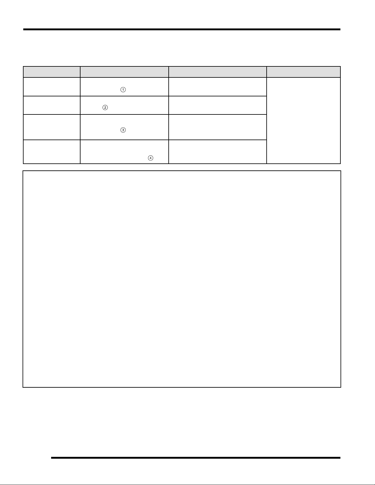
ITEM LUBE REC. METHOD
Oil Fill Cap
- Under Cargo Box Access Panel
Oil Filter
- Behind Engine Access Panel
Engine Coolant
- Under Front Hood / Access Panel
:
/ Dipstick3:
Polaris PS-4 or
Polaris PS-4
Extreme Duty
Polaris 60/40
Coolant
Add oil to proper level
on dipstick
Maintain coolant level
in coolant reservoir
bottle
.
* More often under severe use, such as operation in water or under severe loads.
FREQUENCY*
Perform a break-in oil and
filter change at 25 hrs or
one month; perform every
50 hrs thereafter
Check level daily; change
coolant every two years
2.6
9925724 R01 - 2014-2015 RZR XP 1000 / RZR XP4 1000 Service Manual
© Copyright 2014 Polaris Industries Inc.
Page 39

Maintenance Quick Reference, Continued...
1
2
3
MAINTENANCE
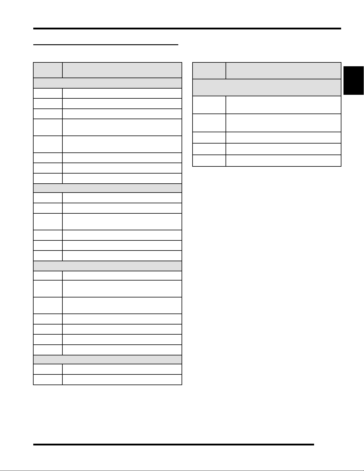
ITEM LUBE REC. METHOD
Brake Fluid
Front Gearcase
Transmission Polaris AGL
* More often under severe use, such as operation in water or under severe loads.
Polaris DOT 4 Brake
Fluid
Polaris Demand
Drive
Maintain fluid level between
“MAX and “MIN” lines on the
master cylinder reservoir
Add lubricant until it is visible at
the fill hole threads
oz. (250 ml))
Add lubricant until it is visible at
the fill hole threads
( 8.5
FREQUENCY*
Check level during pre-ride inspection;
change fluid every two years
Initial level check at 25 hours or 1
month; Change lubricant at 100 hours
or every 12 months, whichever comes
first
2
2.7
9925724 R01 - 2014-2015 RZR XP 1000 / RZR XP4 1000 Service Manual
© Copyright 2014 Polaris Industries Inc.
Page 40
1
2
3
4
MAINTENANCE
Grease Lubrication Points
There are grease fittings at each front A-arm pivot point, each rear torsion bar bushing and on the front propshaft
yokes. Apply grease until all traces of water have been purged out at each of these areas.
ITEM METHOD RECOMMENDED LUBE
Front A-arm
Pivot Bushings
Propshaft Yokes
Front Stabilizer
Bar Bushings
(INT’L)
Rear Torsion Bar
Bushings
Grease 3 fittings on each side
of the vehicle
Grease middle and rear
fittings
Grease the fitting on each side
of the vehicle
Grease 2 fittings through the
skid plate access holes on
each side of the vehicle
Polaris All Season Grease
Polaris Premium U-Joint Grease
Polaris All Season Grease
Polaris All Season Grease
FREQUENCY
Grease fittings every 500
miles (800 km); Grease
before long periods of
storage, and after
thoroughly washing or
submerging the vehicle
*There is no grease point on the upper control arm rear mount.
2.8
9925724 R01 - 2014-2015 RZR XP 1000 / RZR XP4 1000 Service Manual
© Copyright 2014 Polaris Industries Inc.
Page 41
LUBRICANTS / SERVICE PRODUCTS
Polaris Lubricants, Maintenance and Service Products
MAINTENANCE
PART
NO.
Engine Lubricant
2870791
2876244
2876245
2878920
2878919
2540086
2879723
2879324
Gearcase / Transmission Lubricants
2878068
2878069
2878070
2877922
2877923
2870465
Grease / Specialized Lubricants
DESCRIPTION
Fogging Oil (12 oz. Aerosol)
PS-4 Synthetic 4-Cycle Engine Oil (Quart)
PS-4 Synthetic 4-Cycle Engine Oil (Gallon)
PS-4 Extreme Duty Synthetic 4-Cycle
Engine Oil (Quart)
PS-4 Extreme Duty Synthetic 4-Cycle
Engine Oil (Gallon)
Engine Oil Filter
Engine Oil Change Kit (PS-4)
Engine Oil Change Kit (PS-4 Extreme Duty)
AGL (1 Qt.) (12 Count)
AGL (1 Gal.) (4 Count)
AGL Gearcase Lubricant (2.5 Gal.) (2
Count)
Demand Drive (Quart)
Demand Drive (2.5 Gallon)
Oil Pump for 1 Gallon Jug
PART
NO.
Additives / Sealants / Thread Locking Agents /
Misc.
2871950
2871326
2870652
2872189
2871557
NOTE: The number count indicated by each part
number in the table above indicates the number of
units that are shipped with each order.
DESCRIPTION
Loctite® Threadlock 242
(6 ml.) (12 count)
Premium Carbon Clean
(12 oz.) (12 count)
Fuel Stabilizer (16 oz.) (12 count)
DOT 4 Brake Fluid (12 count)
Crankcase Sealant, 3-Bond 1215 (5 oz.)
2
2871312 Grease Gun Kit
2871322
2871423
2871460
2871515
2871551
2871329
Coolant
2871323
2871534
NOTE: Each item can be purchased separately at
your local Polaris dealer.
Premium All Season Grease
(3 oz. cartridge) (24 Count)
Premium All Season Grease
(14 oz. cartridge) (10 Count)
Starter Drive Grease (12 Count)
Premium U-Joint Lube (3 oz.) (24 Count)
Premium U-Joint Lube (14 oz.) (10 Count)
Dielectric Grease (Nyogel™)
60/40 Coolant (Gallon) (6 Count)
60/40 Coolant (Quart) (12 Count)
9925724 R01 - 2014-2015 RZR XP 1000 / RZR XP4 1000 Service Manual
© Copyright 2014 Polaris Industries Inc.
2.9
Page 42

1
4
3
6
5
MAINTENANCE
GENERAL VEHICLE INSPECTION AND MAINTENANCE
Pre-Ride / Daily Inspection
Perform the following pre-ride inspection daily, and when
servicing the vehicle at each scheduled maintenance.
• Engine Oil - Check for proper level on dipstick (see
Chapter 2 – Engine Oil Level, page 2.17)
• Tires - check condition and pressures
• Fuel tank - fill to proper level
• All brakes - check operation and fluid level and
adjustment (includes parking brake on INT’L
Model)
• Headlights/Taillights/Brakelights - also check
operation of all indicator lights, instrument cluster
and switches
• Ignition switch - check for proper function
• Wheels - check for tightness of wheel nuts and
axle nuts; check to be sure axle nuts are secured
by cotter pins
• Engine Intake Pre-Filter - Inspect pre-filter and
clean with soapy water and low pressure
compressed air if necessary
• PVT Intake Pre-Filter - Inspect pre-filter and clean
with soapy water and low pressure compressed air
if necessary
• Steering - check for free operation noting any
unusual looseness in any area
• Loose parts - visually inspect vehicle for any
damaged or loose nuts, bolts or fasteners
• Engine coolant - check for proper level at the
recovery bottle
• Drive Shaft Boots - Inspect inner and outer boots
for tears or damage on both front and rear drive
shafts
• Check all front and rear suspension components
for wear or damage.
Shift Cable Inspection / Adjustment
Shift cable adjustment may be necessary if symptoms
include:
• No gear position or AWD display on instrument
cluster
• Ratcheting noise on deceleration
• Inability to engage into a gear
• Excessive gear lash (noise)
• Gear selector moving out of desired range
1. Locate the shift cable
case in the right rear wheel well area.
2. Inspect shift cable, clevis pin, pivot bushings
dust boot
. Replace if worn or damaged.
3. If adjustment is required, loosen the lower jam nut
and pull the cable out of the mount2to move the
upper jam nut
.
attached to the transmission
, and
4. Adjust the shift cable so there is the same amount of
cable travel when shifting slightly past HIGH gear
and PARK.
2.10
9925724 R01 - 2014-2015 RZR XP 1000 / RZR XP4 1000 Service Manual
© Copyright 2014 Polaris Industries Inc.
Page 43

5. Thread the upper or lower jam nut as required to
obtain proper cable adjustment.
NOTE: This procedure may require a few
attempts to obtain the proper adjustment.
MAINTENANCE
6. Once the proper adjustment is obtained, place the
shift cable and upper jam nut into the mount. Tighten
the lower jam nut against the mount.
7. Start engine and shift through all gears to ensure the
shift cable is properly adjusted. If transmission still
ratchets after cable adjustment, the transmission will
require service.
2
9925724 R01 - 2014-2015 RZR XP 1000 / RZR XP4 1000 Service Manual
© Copyright 2014 Polaris Industries Inc.
2.11
Page 44

MAINTENANCE
FUEL SYSTEM AND AIR INTAKE
Fuel System
WARNING
Gasoline is extremely flammable and explosive under
certain conditions.
Always stop the engine and refuel outdoors or in a well
ventilated area.
Do not smoke or allow open flames or sparks in or near
the area where refueling is performed or where
gasoline is stored.
Do not overfill the tank. Do not fill the tank neck.
If you get gasoline in your eyes or if you swallow
gasoline, seek medical attention immediately.
If you spill gasoline on your skin or clothing,
immediately wash it off with soap and water
and change clothing.
Never start the engine or let it run in an enclosed area.
Engine exhaust fumes are poisonous and can result in
loss of consciousness or
death in a short time.
Never drain the fuel when the engine is hot.
Severe burns may result.
Fuel Tank Vent Line
Symptoms of a restricted fuel tank vent include the
following: collapsing fuel tank, engine miss or hesitation,
loss of engine performance or high exhaust
temperatures.
1. Remove the seats and the engine service panel.
2. Check the fuel tank vent line for signs of wear,
deterioration or damage. Replace vent line if
necessary.
3. Be sure the vent line is routed properly and secured
with cable tie(s).
NOTE: Make sure vent line is not kinked or
pinched.
2.12
9925724 R01 - 2014-2015 RZR XP 1000 / RZR XP4 1000 Service Manual
© Copyright 2014 Polaris Industries Inc.
Page 45

2
MAINTENANCE
Fuel Pump / Fuel Filters
The fuel pump assembly1is located in the fuel tank
under the passenger seat.
The RZR XP 1000 EFI engine uses a serviceable, highvolume, high-pressure, fuel pump that includes a
preliminary filter
before the pump regulator.
NOTE: Neither filter is serviceable individually. Must
replace the fuel pump as an assembly.
and an internal fine filter3located
Fuel Lines
1. Check the quick-connect fuel line1at the fuel tank
for signs of wear, deterioration, damage or leakage.
Replace line(s) if necessary.
2
2. Locate the fuel supply fitting2through the right rear
wheel well on the upper right side of the engine.
Check the line and quick-connect fitting for signs of
wear, deterioration, damage or leakage. Replace line
if necessary.
3. Be sure fuel lines are routed and retained properly.
Refer to Chapter 4 for fuel pump replacement and all
other information related to the EFI System.
NOTE: Make sure lines are not kinked or
pinched.
2.13
9925724 R01 - 2014-2015 RZR XP 1000 / RZR XP4 1000 Service Manual
© Copyright 2014 Polaris Industries Inc.
Page 46

1
MAINTENANCE
Throttle Pedal Inspection
This vehicle is equipped with Pedal Position Sensor
used to detect when the throttle pedal2is pushed or
released.
The throttle pedal should move freely and always return
back to its idle position when released.
Check throttle pedal periodically.
Engine Intake Pre-Filter Service
It is recommended that the engine intake pre-filter be
inspected daily. The filter should be inspected using the
following procedure:
1. The engine intake pre-filter is located just above the
right rear wheel fender.
2. Loosen the knob on top of the assembly and lift up to
disengage the tab from the cargo box.
3. Inspect the pre-filter. If necessary, clean with soapy
water and dry with low pressure compressed air.
2.14
9925724 R01 - 2014-2015 RZR XP 1000 / RZR XP4 1000 Service Manual
© Copyright 2014 Polaris Industries Inc.
Page 47

1
1
MAINTENANCE
Air Filter Service
Inspect the air filter at the intervals outlined in the
Periodic Maintenance Chart. In extremely dusty
conditions, air filter replacement will be required more
often.
1. Remove the cargo box access panel
2. Disengage the four cover latches2.
.
4. Inspect the air box for oil or water deposits. Wipe
away any deposits with a clean shop towel.
NOTE: If the filter has been soaked with fuel or
oil it must be replaced.
5. Inspect the air filter and replace if necessary.
NOTE: DO NOT attempt to clean the air filter.
6. Place the air filter into the air box and reinstall the air
box cover.
NOTE: Be sure the lower tabs on the air box
cover are properly engaged into the airbox.
7. Engage the cover latches.
8. Reinstall the cargo box access panel.
Intake Duct Drain Inspection
It is recommended that the intake drain be inspected
daily.
1. Access the intake baffle box drain
rear wheel well.
through the left
2
3. Pull cover rearward far enough to remove air filter3.
2. Check the drain to ensure it is not plugged with
debris so it can drain properly. If needed, remove the
drain from the baffle box during inspection.
2.15
9925724 R01 - 2014-2015 RZR XP 1000 / RZR XP4 1000 Service Manual
© Copyright 2014 Polaris Industries Inc.
Page 48
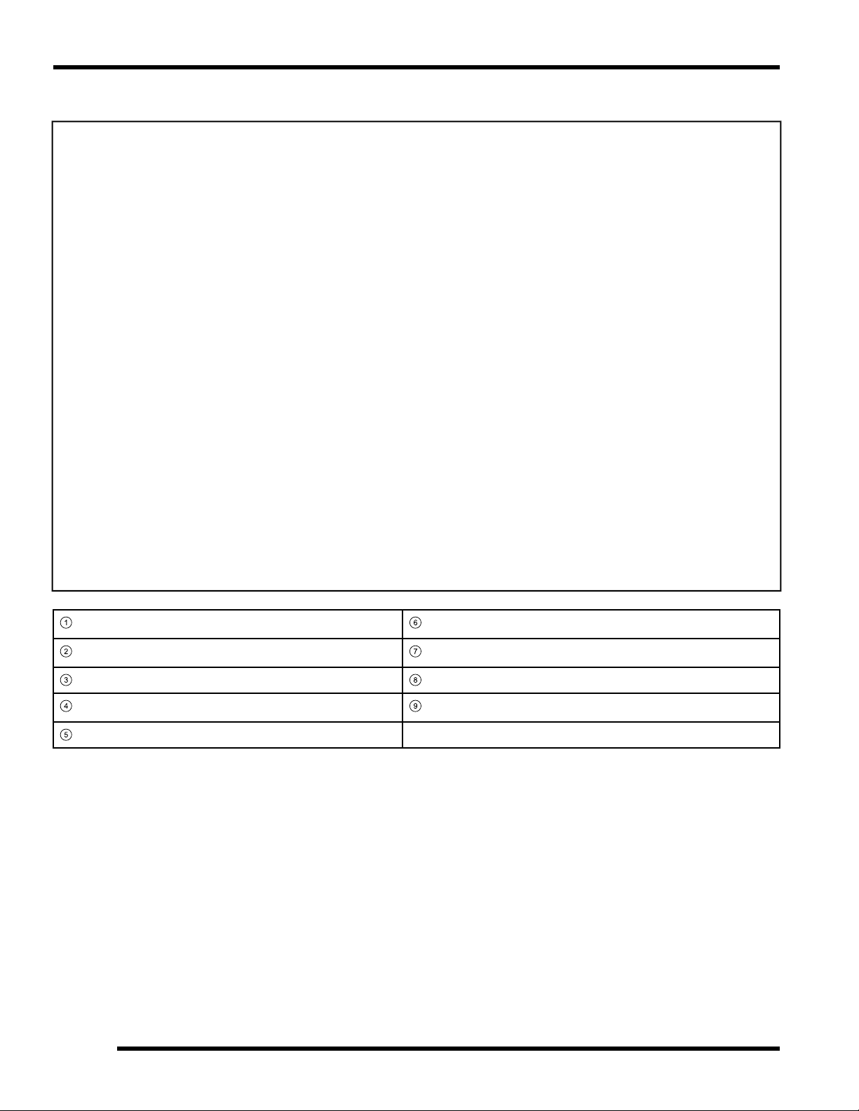
1
6
2
7
3
8
4
9
5
MAINTENANCE
Air Box / Air Filter Assembly View
Intake Airbox Hose
Drain Cap
Airbox
Air Filter
Airbox Cover
Airbox Clip (4)
Vent Hose
Intake Tubes
Engine Intake Housing
2.16
9925724 R01 - 2014-2015 RZR XP 1000 / RZR XP4 1000 Service Manual
© Copyright 2014 Polaris Industries Inc.
Page 49

ENGINE
1
2
MAINTENANCE
Engine Oil Level
The 2014 RZR XP 1000 engine has a wet-sump design,
meaning the engine oil is contained in the bottom of the
crankcase. To check the oil level, follow the procedure
listed below:
Access the oil dipstick through the opening in front of the
passenger rear tire.
Access the oil fill cap through the cargo box access
panel.
Polaris recommends the use of PS-4 Synthetic or PS-4
Extreme Duty Synthetic 4-Cycle Engine Oil.
Recommended Engine Oil:
PS-4 (PN 2876244)
Ambient Temp Range: -35° F to 100° F
PS-4 Extreme Duty (PN 2878920)
Ambient Temp Range: 0° F to 120° F
Capacity: 2.5 Quarts (2.4 L)
1. Position vehicle on a level surface and place the
transmission in PARK.
2. Stop the engine and allow it to cool down before
removing the dipstick.
3. Unlock the dipstick lever
wipe it dry with a clean cloth.
. Remove the dipstick and
4. Reinstall the dipstick and push it into place. Do not
lock the dipstick
NOTE: Make certain the dipstick is inserted all
the way into the dipstick tube to keep the depth
of the dipstick consistent.
5. Remove the dipstick and check the oil level.
6. Add the recommended oil as necessary to bring the
oil level within the SAFE range on dipstick. Do not
overfill (see NOTE below).
NOTE: A rising oil level between checks during
cold weather operation can indicate
contaminants such as gas or moisture collecting
in the crankcase. If the oil level is over the upper
mark, change the oil immediately.
7. Add engine oil through the oil fill cap
top of the valve cover, under the cargo box access
panel.
located on
2
8. When finished, reinstall dipstick and lock the lever.
2.17
9925724 R01 - 2014-2015 RZR XP 1000 / RZR XP4 1000 Service Manual
© Copyright 2014 Polaris Industries Inc.
Page 50

1
2
MAINTENANCE
Engine Oil and Filter Change
Always change engine oil and filter at the intervals
outlined in the Periodic Maintenance Chart. Always
change the oil filter whenever changing the engine oil.
The engine oil dipstick is located on the front side of the
engine. Access the dipstick through the engine service
panel.
The engine oil fill cap is located on top of the valve cover.
Access the oil fill cap through the cargo box access
panel.
The crankcase drain plug is located on the bottom of the
crankcase. Access the drain plug through the skid plate
access hole located directly under the crankcase.
1. Position vehicle on a level surface and place the
transmission in PARK.
2. Stop the engine and allow it to cool down.
3. Clean the area around the crankcase drain plug.
CAUTION
Use caution when performing this procedure.
Do not allow hot engine oil to come into contact with
skin, as serious burns may result.
4. Place a drain pan under the engine crankcase and
remove the drain plug
completely.
. Allow the oil to drain
6. Using the Oil Filter Wrench (PU-50105), turn the oil
filter
7. Using a clean dry cloth, clean the filter sealing
surface on the engine crankcase.
8. Lubricate the O-ring on the new oil filter with a film of
fresh engine oil. Check to make sure the O-ring is in
good condition. Install it by hand until the O-ring
contacts the sealing surface, then turn an additional
1/2 turn.
counter-clockwise to remove it.
Oil Filter Wrench:
PU-50105: 2.5″ (64 mm)
Oil Filter Torque:
Turn by hand until filter O-ring contacts sealing surface,
then turn an additional 1/2 turn.
9. Replace the sealing washer on drain plug.
NOTE: The sealing surface on the drain plug
should be clean and free of burrs, nicks or
scratches.
10. Reinstall the engine crankcase drain plug. Torque
drain plug to specification.
5. Remove the seats and engine service panel to
access the oil filter.
Engine Oil Drain Plug:
12 ft-lbs (16 Nm)
2.18
9925724 R01 - 2014-2015 RZR XP 1000 / RZR XP4 1000 Service Manual
© Copyright 2014 Polaris Industries Inc.
Page 51

1
MAINTENANCE
11. Remove oil fill cap (see Chapter 2 – Engine Oil
Level, page 2.17). Fill engine with 2.5 quarts (2.4 L)
of recommended engine oil.
Recommended Engine Oil:
PS-4 (PN 2876244)
Ambient Temp Range: -35° F to 100° F
PS-4 Extreme Duty (PN 2878920)
Ambient Temp Range: 0° F to 120° F
Capacity: 2.5 Quarts (2.4 L)
12. Verify the transmission is still in PARK.
13. Start the engine and allow it to idle for 30 seconds.
14. Stop the engine and inspect for oil leaks. Wait at
least 15 seconds before removing the dipstick.
15. Unlock the dipstick lever. Remove the dipstick and
wipe it dry with a clean cloth (see Chapter 2 –
Engine Oil Level, page 2.17).
16. Reinstall the dipstick and push it into place. Do not
lock the dipstick
Engine Crankcase Breather Hose Inspection
The engine crankcase is equipped with a breather hose.
Inspect the breather hose for possible kinks or wear. The
hose is form fitted for proper fit.
Follow the breather hose
engine intake duct.
NOTE: Make sure hoses are not kinked or pinched.
from the crankcase to the
2
NOTE: Make certain the dipstick is inserted all
the way into the dipstick tube to keep the depth
of the dipstick consistent.
17. Remove the dipstick and check the oil level.
18. Add the recommended oil as necessary to bring the
oil level within the SAFE range on dipstick. Do not
overfill.
19. When finished, reinstall the oil fill cap, oil dipstick and
lock the lever.
20. Reinstall the cargo box access panel, engine service
panel and seats.
21. Dispose of used oil and filter properly.
2.19
9925724 R01 - 2014-2015 RZR XP 1000 / RZR XP4 1000 Service Manual
© Copyright 2014 Polaris Industries Inc.
Page 52

MAINTENANCE
Engine Cylinder Leakdown Test
A cylinder leak-down test is the best indication of engine
condition. Follow tester manufacturer’s instructions to
perform a cylinder leak-down test. Never use high
pressure leakage testers as crankshaft seals may
dislodge and leak.
Cylinder Leakage Service Limit: 20%
If leakage exceeds service limit, inspect the engine
for the cause.
Valve Clearance Inspection
NOTE: Valve clearance inspection should be
performed on a cold engine, at room temperature.
1. Remove the driver’s seat. Disconnect the negative
(-) battery cable.
2. Remove the engine access panel.
3. Remove eight screws retaining the outer clutch
cover.
4. Maneuver the outer clutch cover to allow access to
the drive clutch, in order to rotate the engine.
NOTE: Removal of left rear wheel or left rear
shock is NOT necessary to perform this
procedure.
5. Remove the spark plug wires to gain access to valve
cover as shown below.
2.20
9925724 R01 - 2014-2015 RZR XP 1000 / RZR XP4 1000 Service Manual
© Copyright 2014 Polaris Industries Inc.
Page 53

13
14
MAINTENANCE
6. Remove the four T40 bolts retaining the valve cover.
7. The engine will need to be rotated four times to
inspect all eight valve clearances
be measured at each camshaft lobe position.
. Two valves can
9. Measure the valve clearance using a feeler gauge.
2
10. If the valve clearance is out of specification, see
Chapter 3 – Valve Clearance Adjustment, page
3.84.
Intake Valve Clearance (cold):
.006 ± .002″ (0.15 ± 0.05 mm)
Exhaust Valve Clearance (cold):
.008 ± .002″ (0.20 ± 0.05 mm)
NOTE: Remove spark plugs to aid engine
rotation.
8. Rotate the drive clutch counter-clockwise until the
cam lobes
are facing up.
above the valves you are inspecting
11. Repeat steps 18-20 until all eight valves have been
inspected.
12. If previously removed, apply anti-seize compound to
the spark plug threads and reinstall the spark plugs.
Torque spark plugs to specification.
Spark Plug Torque:
7 ft-lbs (10 Nm)
13. Inspect the valve cover seal and replace if
necessary.
14. Install NEW isolators on the valve cover bolts. Install
the valve cover and the four T40 bolts. Torque bolts
to specification.
Valve Cover Bolts:
7 ft-lbs (10 Nm)
2.21
9925724 R01 - 2014-2015 RZR XP 1000 / RZR XP4 1000 Service Manual
© Copyright 2014 Polaris Industries Inc.
Page 54

MAINTENANCE
15. Install the spark plug wires back into their correct
location.
16. Install the push rivet that retains the heat shield to
the frame cross member.
17. Install the spark plug wires. Ensure wires are
installed on their proper cylinder spark plug and
pushed down all the way so they engage onto the
spark plugs.
NOTE: The engine will misfire if the spark plug
wires are installed incorrectly. The spark plug
wires are marked with PTO and MAG and should
be installed to the corresponding cylinder.
18. Install outer clutch cover and eight retaining screws.
Torque screws to specification.
Outer Clutch Cover Screws:
50 in-lbs (5 Nm)
19. Connect the negative (-) battery cable to the battery
and install the seat.
20. Start the engine to ensure proper operation.
21. Install the engine access panel.
2.22
9925724 R01 - 2014-2015 RZR XP 1000 / RZR XP4 1000 Service Manual
© Copyright 2014 Polaris Industries Inc.
Page 55
TRANSMISSION AND FRONT GEARCASE
1
2
3
Specification Chart
MAINTENANCE
GEARCASE LUBRICANT CAPACITY
without turf mode:
44 oz. (1300 ml)
Transmission AGL
Front Gearcase Demand Drive
with turf mode:
40.5 oz. (1200 mL)
8.5oz. (250 ml) 10 ft-lbs (14 Nm)
Transmission Lubrication
NOTE: It is important to follow the transmission
maintenance intervals described in the Periodic
Maintenance Chart. Regular lubricant level
inspections should be performed as well.
The transmission lubricant level should be checked and
changed in accordance with the maintenance schedule.
• Be sure vehicle is positioned on a level surface
when checking or changing the lubricant.
• Check vent hose to be sure it is routed properly
and unobstructed.
Transmission Lubricant Level Check
The fill plug is located on the rear portion of the
transmission gearcase. Access the fill plug at the rear of
the vehicle. Maintain lubricant level even with the bottom
of the fill plug hole.
1. Position vehicle on a level surface.
2. Remove the fill plug
.
and check the lubricant level
FILL / DRAIN PLUG TORQUE
14 ft-lbs (19 Nm)
4. Reinstall the fill plug and torque to specification.
Transmission Fill / Drain Plug Torque:
14 ft-lbs (19 Nm)
Transmission Lubricant Change
The drain plug is located on the bottom of the
transmission gearcase. Access the drain plug
through the drain hole in the skid plate.
5. Remove the fill plug (see Chapter 2 – Transmission
Lubrication, page 2.23).
6. Place a drain pan under the transmission drain plug.
7. Remove drain plug
completely.
and allow lubricant to drain
2
8. Clean the drain plug magnetic surface.
9. Reinstall the drain plug and torque to specification.
3. If lubricant level is not even with bottom threads, add
recommended lubricant as needed. Do not overfill.
2.23
9925724 R01 - 2014-2015 RZR XP 1000 / RZR XP4 1000 Service Manual
© Copyright 2014 Polaris Industries Inc.
Page 56

1
MAINTENANCE
10. Add the recommended amount of lubricant through
the fill plug hole. Maintain the lubricant level at the
bottom of the fill plug hole when filling the
transmission. Do not overfill.
Recommended Transmission Lubricant:
AGL (PN 2878068) (Quart)
Capacity: 44 oz. (1300 ml)
Capacity (INT’L): 41 oz. (1200 ml)
11. Reinstall the fill plug and torque to specification.
Transmission Fill / Drain Plug Torque:
14 ft-lbs (19 Nm)
12. Check for leaks. Dispose of used lubricant properly.
Front Gearcase Lubrication
NOTE: It is important to follow the front gearcase
maintenance intervals described in the Periodic
Maintenance Chart. Regular fluid level inspections
should be performed as well.
The front gearcase fluid level should be checked and
changed in accordance with the maintenance schedule.
• Be sure vehicle is positioned on a level surface
when checking or changing the fluid.
• Check vent hose to be sure it is routed properly
and unobstructed.
Front Gearcase Fluid Level Check
The fill plug is located on the bottom right side of the front
gearcase. Access the fill plug through the right front
wheel well. Maintain fluid level even with the bottom of
the fill plug hole.
1. Position vehicle on a level surface.
2. Remove the fill plug
and check the fluid level.
3. If fluid level is not even with the bottom threads, add
the recommended fluid as needed. Do not overfill.
4. Reinstall the fill plug and torque to specification.
Front Gearcase Fill / Drain Plug Torque:
10 ft-lbs (14 Nm)
Front Gearcase Fluid Change:
The drain plug is located on the bottom of the front
gearcase. Access the drain plug through the access
hole in the frame underneath the front gearcase.
5. Remove the fill plug (see Chapter 2 – Front
Gearcase Lubrication, page 2.24).
2.24
9925724 R01 - 2014-2015 RZR XP 1000 / RZR XP4 1000 Service Manual
© Copyright 2014 Polaris Industries Inc.
Page 57

6. Place a drain pan under the front gearcase drain
2
plug.
7. Remove the drain plug
completely.
8. Clean the drain plug magnetic surface.
9. Reinstall the drain plug and torque to specification.
10. Add the recommended amount of fluid through the fill
hole. Maintain the fluid level even with the bottom
threads of the fill plug hole.
and allow fluid to drain
MAINTENANCE
2
Recommended Front Gearcase Fluid:
Polaris Demand Drive
(PN 2877922) (Quart)
Capacity: 8.5 oz. (250 mL)
11. Reinstall the fill plug and torque to specification.
Front Gearcase Fill / Drain Plug Torque:
10 ft-lbs (14 Nm)
12. Check for leaks. Dispose of used fluid properly.
2.25
9925724 R01 - 2014-2015 RZR XP 1000 / RZR XP4 1000 Service Manual
© Copyright 2014 Polaris Industries Inc.
Page 58

MAINTENANCE
COOLING SYSTEM
Cooling System Overview
The engine coolant level is controlled, or maintained, by
the recovery system. The recovery system components
are the recovery bottle, radiator filler neck, radiator
pressure cap and connecting hose.
As coolant operating temperature increases, the
expanding (heated) excess coolant is forced out of the
radiator past the pressure cap and into the recovery
bottle. As engine coolant temperature decreases the
contracting (cooled) coolant is drawn back up from the
tank past the pressure cap and into the radiator.
NOTE: Some coolant level drop on new machines is
normal as the system is purging itself of trapped air.
Observe coolant levels often during break-in period.
Overheating of engine could occur if air is not fully
purged from system.
Polaris Premium 50/50 Antifreeze is premixed and
ready to use. Do not dilute with water.
Coolant Strength
Test the strength of the coolant using an antifreeze
hydrometer.
Coolant Level Inspection
The pressure cap1and recovery bottle2are located
under the front hood of the vehicle. The coolant level
must be maintained between the minimum and
maximum levels indicated on the recovery bottle.
With the engine at operating temperature, the coolant
level should be between the upper and lower marks on
the coolant recovery bottle. If not, perform the following
procedure:
1. Position the vehicle on a level surface.
2. Remove the front hood.
3. View the coolant level in the recovery bottle.
4. If the coolant level is below the MIN line, inspect the
coolant level in the radiator.
• A 50/50 mixture of antifreeze and distilled water
will provide the optimum cooling, corrosion
protection, and antifreeze protection.
• Do not use tap water, straight antifreeze or straight
water in the system. Tap water contains minerals
and impurities which build up in the system.
• Straight water or antifreeze may cause the system
to freeze, corrode, or overheat.
Recommended Coolant:
Polaris Premium Pre-Mixed Antifreeze
(PN 2880514) (Quart)
(PN 2880513) (Gallon)
NOTE: If overheating is evident, allow system to
cool completely and check coolant level in the
radiator and inspect for signs of trapped air in
system.
WARNING
Never remove the pressure cap when the engine is
warm or hot. Escaping steam can cause severe burns.
The engine must be cool before removing the pressure
cap.
5. Remove the pressure cap. Using a funnel, add
coolant to the top of the filler neck.
6. Reinstall the pressure cap.
NOTE: Use of a non-standard pressure cap will
not allow the recovery system to function
properly.
7. Remove recovery bottle cap and add coolant using a
funnel.
2.26
9925724 R01 - 2014-2015 RZR XP 1000 / RZR XP4 1000 Service Manual
© Copyright 2014 Polaris Industries Inc.
Page 59
1
2
3
4
5
6
MAINTENANCE
8. Fill recovery bottle to MAX level with recommended
coolant or 50/50 or 60/40 mixture of antifreeze and
distilled water as required for freeze protection in
your area.
Recommended Coolant:
Polaris Premium Pre-Mixed Antifreeze
PN 2871534 (Quart)
PN 2871323 (Gallon)
9. Reinstall the recovery bottle cap.
10. If coolant was required, start engine and check for
leaks. Make sure radiator fins are clean to prevent
overheating.
Cooling System Pressure Test
Refer to ENGINE COOLING SYSTEM, page 3.13.
Cooling System Hoses
1. Inspect all vehicle hoses for cracks, deterioration,
abrasion or leaks. Replace if necessary.
2
ITEM
DESCRIPTION
Recovery Bottle
Engine Hoses
Radiator Hoses
To Thermostat Housing
To Waterpump
To Radiator
2.27
9925724 R01 - 2014-2015 RZR XP 1000 / RZR XP4 1000 Service Manual
© Copyright 2014 Polaris Industries Inc.
Page 60

7
8
9
10
1
2
3
MAINTENANCE
2. Inspect all engine hoses for cracks, deterioration,
abrasion or leaks. Replace if necessary.
ITEM
DESCRIPTION
Bypass Hose
Waterpump Outlet Hose
Oil Cooler Inlet Hose
Oil Cooler Outlet Hose
3. Check tightness and condition of all hose spring
clamps. Replace if necessary.
Radiator Inspection / Cleaning
1. Check radiator air passages for restrictions or
damage.
ITEM
2. Carefully straighten any bent radiator fins.
3. Remove any obstructions with low pressure
compressed air or low pressure water.
DESCRIPTION
Radiator
Shroud
Fan
CAUTION
Washing the vehicle with a high-pressure washer could
damage the radiator fins and impair the radiators
effectiveness. Use of a high-pressure washer is not
recommended.
2.28
9925724 R01 - 2014-2015 RZR XP 1000 / RZR XP4 1000 Service Manual
© Copyright 2014 Polaris Industries Inc.
Page 61

Coolant Drain / Fill
1
1. Remove the front hood.
WARNING
MAINTENANCE
Never drain the coolant when the engine and radiator
are warm or hot. Hot coolant can cause severe burns.
Allow engine and radiator to cool.
2. Slowly remove the pressure cap to relieve any
cooling system pressure.
3. Place a suitable drain pan underneath the radiator
fitting on the front right side of the vehicle.
4. Drain the coolant from the radiator by removing the
lower coolant hose from the radiator as shown
.
2
5. Allow coolant to drain completely. Properly dispose
of the used coolant.
6. Reinstall coolant hose and reposition the spring
clamp.
7. Remove the pressure cap. Using a funnel, add the
recommended coolant to the top of the filler neck
and fill the recovery bottle to the MAX level.
8. Refer to Cooling System Bleeding Procedure, page
3.18.
Recommended Coolant:
Polaris Premium Pre-Mixed Antifreeze
(PN 2871534) (Quart)
(PN 2871323) (Gallon)
2.29
9925724 R01 - 2014-2015 RZR XP 1000 / RZR XP4 1000 Service Manual
© Copyright 2014 Polaris Industries Inc.
Page 62

1
MAINTENANCE
PVT / FINAL DRIVE / WHEEL AND TIRE
Drive Clutch / Driven Clutch / Belt Service
Refer to PVT SYSTEM SERVICE, page 5.8 for service
and removal procedures.
PVT Intake Pre-Filter Service
It is recommended that the PVT intake pre-filter be
inspected daily. The filter should be inspected using the
following procedure:
1. The PVT intake pre-filter is located just above the left
rear wheel fender.
2. Loosen the knob on top of the assembly and lift up to
disengage the tab from the cargo box.
PVT Drying
NOTE: After operating in water, the vehicle’s PVT
system should be checked immediately. Use the
following instructions to dry it out before operating.
The PVT drain plug is located at the bottom of the outer
clutch cover. Access the drain plug through the left rear
wheel well.
1. Using a flat blade screwdriver, remove the PVT drain
plug
and O-ring from the outer clutch cover.
3. Inspect the pre-filter. If necessary, clean with soapy
water and dry with low pressure compressed air.
2. Allow the water to drain out completely.
3. Reinstall the drain plug and O-ring.
4. Place the transmission in PARK, apply the brake and
start the engine.
5. Apply varying throttle for 10-15 seconds to expel the
moisture and air-dry the belt and clutches.
NOTE: Do not hold the throttle pedal wide open
for more than 5 seconds.
6. Allow the engine RPM to return to idle, then shift the
transmission into low gear.
7. Test the PVT system for belt slippage. If the belt
slips, repeat the process or remove the outer clutch
cover to inspect the PVT system (see Chapter 4 –
PVT SYSTEM SERVICE, page 5.8 for service and
removal procedures).
NOTE: If the vehicle has ingested a large
amount of water into the PVT system and has not
been operated for a period of time, be sure to
check the PVT system components for water
damage.
2.30
9925724 R01 - 2014-2015 RZR XP 1000 / RZR XP4 1000 Service Manual
© Copyright 2014 Polaris Industries Inc.
Page 63

1
2
MAINTENANCE
Drive Shaft Boot Inspection
Inspect the front and rear drive shaft boots
damage, tears, wear or leaking grease. If the boots
exhibit any of these symptoms, they should be replaced.
Check to see the boot clamps
Refer to DRIVE SHAFT CV JOINT / BOOT
REPLACEMENT , page for drive shaft boot
replacement.
are properly positioned.
for
Wheel and Hub Torque Table
ITEM SPECIFICATION
Wheel Nuts
(Cast Aluminum Wheels)
Hub Retaining Nuts
(Front and Rear)
Beadlock Screws
NOTE: Do not lubricate the stud or the lug nut.
120 ft-lbs (163 Nm)
110 ft-lbs (149 Nm)
Step 1: 24 in-lbs (3 Nm)
Step 2: 7 ft-lbs (10 Nm)
Wheel Removal
1. Position the vehicle on a level surface.
2. Place the transmission in PARK and stop the engine.
3. Loosen the wheel nuts slightly. If wheel hub removal
is required, remove the wheel cap, cotter pin and
loosen the hub nut slightly.
4. Elevate the appropriate side of the vehicle by placing
a suitable stand under the frame.
5. Remove the wheel nuts and remove the wheel.
2
2.31
9925724 R01 - 2014-2015 RZR XP 1000 / RZR XP4 1000 Service Manual
© Copyright 2014 Polaris Industries Inc.
Page 64

5
2
1
3
4
MAINTENANCE
Wheel Installation
1. Verify the transmission is still in PARK.
2. Place the wheel in the correct position on the wheel
hub
outside and rotation arrows on the tire point toward
forward rotation.
3. Attach the wheel nuts
4. Carefully lower the vehicle to the ground.
5. Torque the wheel nuts and/or hub nut
proper torque specification (see Chapter 2 – Wheel
and Hub Torque Table, page 2.31).
6. If hub nut was removed, install a new cotter pin
after the hub nut has been tightened. If the holes do
not line up, turn the hub nut counter-clockwise until
the cotter pin can be installed.
. Be sure the valve stem
and finger tighten them.
is toward the
to the
Tire Inspection
• Improper tire inflation may affect vehicle
maneuverability.
• When replacing a tire always use original
equipment size and type.
• The use of non-standard size or type tires may
affect vehicle handling.
WARNING
Operating with worn tires will increase the possibility of
the vehicle skidding easily with possible loss of control.
Worn tires can cause an accident.
Always replace tires when the usable tread depth has
worn out.
Tire Pressure
Remove the valve stem cap and check tire pressure
using the tire pressure gauge included in the vehicle’s
tool kit.
CAUTION
If wheels are improperly installed it could affect vehicle
handling and tire wear. On vehicles with tapered wheel
nuts, make sure tapered end of nut goes into taper on
wheel.
CAUTION
Maintain proper tire pressure.
Refer to the warning tire pressure decal
applied to the vehicle.
TIRE PRESSURE INSPECTION (COLD)
Model Front Rear
XP
XP4
High Lifter 18 psi (124 kPa) 18 psi (124 kPa)
16 psi (110 kPa) 16 psi (110 kPa)
19 psi (131 kPa) 21 psi (145 kPa)
2.32
9925724 R01 - 2014-2015 RZR XP 1000 / RZR XP4 1000 Service Manual
© Copyright 2014 Polaris Industries Inc.
Page 65

Beadlock Rims (Desert Edition)
The RZR XP Desert Edition model comes with Walker
Evans™ beadlock rims. The beadlock does not come set
up from factory, but may be changed to use the beadlock
feature.
To make the beadlock rim functional:
1. Deflate the tire.
2. Remove the beadlock screws and beadlock ring.
MAINTENANCE
Beadlock Screws:
Step 1: 24 in-lbs (3 Nm)
Step 2: 7 ft-lbs (10 Nm)
2
3. Dismount the tire on the side with the beadlock holes.
4. Place the beadlock ring so the tire is sandwiched
between the rim and the ring making sure the valve
stem is aligned with the slot in the ring.
5. Install bolts and thread them to 24 in-lbs (3 Nm).
6. Tighten in a criss-cross pattern to 7 ft-lbs (10 Nm).
NOTE: Beadlock bolts should be checked and
retorqued every 300 miles (450 km).
7. Seat bead and inflate to 16 psi.
9925724 R01 - 2014-2015 RZR XP 1000 / RZR XP4 1000 Service Manual
2.33
© Copyright 2014 Polaris Industries Inc.
Page 66
2
MAINTENANCE
ELECTRICAL AND IGNITION SYSTEM
Battery Maintenance
Keep battery terminals and connections free of
corrosion. If cleaning is necessary, remove the corrosion
with a stiff wire brush. Wash with a solution of one
tablespoon baking soda and one cup water. Rinse well
with tap water and dry off with clean shop towels. Coat
the terminals with dielectric grease or petroleum jelly.
WARNING
CALIFORNIA PROPOSITION 65 WARNING:
Batteries, battery posts, terminals and related
accessories contain lead and lead compounds, and
other chemicals known to the State of California to
cause cancer and birth defects or other reproductive
harm.
WASH HANDS AFTER HANDLING.
WARNING
Battery Charging / Off Season Storage
Refer to Charging Procedure , page 11.37and Battery
Off Season Storage, page 11.36.
Battery Removal
1. Remove the driver’s seat to access the battery1.
NOTE: Battery is located under left rear seat on
RZR XP 4 1000
Battery electrolyte is poisonous. It contains sulfuric
acid. Serious burns can result from contact with skin,
eyes or clothing. Antidote:
External: Flush with water.
Internal: Drink large quantities of water or milk. Follow
with milk of magnesia, beaten egg, or vegetable oil. Call
physician immediately.
Eyes: Flush with water for 15 minutes and get prompt
medical attention.
Batteries produce explosive gases.
Keep sparks, flame, cigarettes, etc. away. Ventilate
when charging or using in an enclosed space. Always
shield eyes when
working near batteries.
KEEP OUT OF REACH OF CHILDREN.
NOTE: Batteries must be fully charged before use
or battery life will be reduced by 10-30% of full
potential. Charge battery according to “Charging
Procedure”, page 11.37. Do not use the vehicle’s
stator/alternator to charge a new battery.
2. Disconnect the black (negative) battery cable(s).
3. Disconnect the red (positive) battery cable(s).
CAUTION
To reduce the chance of sparks: Whenever removing
the battery, disconnect the black (negative) cable first.
When reinstalling the battery, install the black
(negative) cable last.
4. Remove the battery hold-down bracket
.
5. Lift the battery out of the vehicle.
2.34
9925724 R01 - 2014-2015 RZR XP 1000 / RZR XP4 1000 Service Manual
© Copyright 2014 Polaris Industries Inc.
Page 67

1
2
MAINTENANCE
Battery Installation
NOTE: Using a new battery that has not been fully
charged can damage the battery and result in a
shorter life. It can also hinder vehicle performance.
Refer to Charging Procedure , page 11.37before
installing the battery.
1. Ensure the battery is fully charged.
2. Place the battery in the battery holder and secure
with hold-down strap.
3. Coat the terminals with dielectric grease or
petroleum jelly.
4. Connect and tighten the red (positive) cable(s) first.
5. Connect and tighten the black (negative) cable (s)
last.
Engine / Chassis Electrical Ground
Inspect the ground cable connections. Remove ground
terminals and clean if necessary.
1. The chassis ground connection
start solenoid
rear wheel area.
2. Inspect the chassis ground terminals. Be sure the
grounds are clean and tight.
, can be accessed through the left
, located below the
2
6. Verify that cables are properly routed and reinstall
the driver’s seat.
2.35
9925724 R01 - 2014-2015 RZR XP 1000 / RZR XP4 1000 Service Manual
© Copyright 2014 Polaris Industries Inc.
Page 68
1
2
MAINTENANCE
Spark Plug Service
Inspect and replace the spark plugs at the intervals
outlined in the Periodic Maintenance Chart.
1. Remove the cargo box access panel
.
WARNING
A hot engine can cause serious burns. Allow engine to
cool or wear protective gloves when removing the spark
plugs.
2. Remove both spark plug caps
.
5. Remove spark plugs using a 5/8” spark plug socket
with an extension.
6. Inspect electrodes for wear and carbon buildup.
Look for a sharp outer edge with no rounding or
erosion of the electrodes.
7. Clean with electrical contact cleaner or a glass bead
spark plug cleaner only. CAUTION: A wire brush or
coated abrasive should not be used.
8. Measure gap with a wire gauge. Adjust gap if
necessary by carefully bending the side electrode.
9. If necessary, replace spark plug with proper type.
CAUTION: Severe engine damage may occur if the
incorrect spark plug is used.
NOTE: Note MAG and PTO reference decals on
spark plug wires for reassembly.
3. Clean out plug wells with compressed air to remove
any loose dirt or debris.
4. Rinse plug wells with water and dry with compressed
air.
NOTE: Spark plug wells have drain holes built
into the cylinder head to allow water to drain out.
Recommended Spark Plug:
Champion RG4YCX
10. Apply anti-seize compound to the spark plug
threads.
11. Install spark plugs and torque to specification.
Spark Plug Torque:
7 ft-lbs (10 Nm)
12. Install the plug caps to the appropriate cylinder by
referencing the MAG and PTO spark plug wire
decals. Ensure wires are pushed down all the way so
they engage onto the spark plugs.
13. Reinstall the cargo box access panel.
2.36
9925724 R01 - 2014-2015 RZR XP 1000 / RZR XP4 1000 Service Manual
© Copyright 2014 Polaris Industries Inc.
Page 69

1
2
3
MAINTENANCE
STEERING
Steering Inspection
The steering components should be checked periodically
for loose fasteners, worn tie rod ends, ball joints and
damage. Also check to make sure all cotter pins are in
place. If cotter pins are removed, they must be replaced.
Replace any worn or damaged steering components.
Steering should move freely through the entire range of
travel without binding. Check routing of all cables, hoses,
and wiring to be sure the steering mechanism is not
restricted or limited.
NOTE: Check front end alignment whenever
steering components are replaced.
WARNING
Due to the critical nature of the procedures outlined in
this chapter, Polaris recommends steering component
repair and adjustment be performed by an authorized
Polaris MSD certified technician.
Steering Wheel Freeplay
Check steering wheel for specified freeplay and
operation.
1. Position the vehicle on level ground.
2. Lightly turn the steering wheel left and right.
3. There should be 0.8-1.0″ (20-25 mm) of freeplay.
4. If there is excessive freeplay or the steering feels
rough, inspect the following components.
• Tie Rod Ends
• Steering Shaft U-Joints
• Steering Gearbox
2
2.37
9925724 R01 - 2014-2015 RZR XP 1000 / RZR XP4 1000 Service Manual
© Copyright 2014 Polaris Industries Inc.
Page 70

MAINTENANCE
Tie Rod End / Wheel Hub Inspection
• To check for play in the tie rod end, grasp the
steering tie rod, pull in all directions feeling for
movement.
• Replace any worn steering components. Steering
should move freely through entire range of travel
without binding.
• Elevate front end of machine so front wheels are
off the ground. Check for any looseness in front
wheel/hub assembly by grasping the tire firmly at
top and bottom first, and then at front and rear. Try
to move the wheel and hub by pushing inward and
pulling outward.
Wheel Toe Alignment Inspection
1. Place machine on a smooth level surface and set
steering wheel in a straight ahead position. Secure
the steering wheel in this position.
2. Place a chalk mark on the center line of the front
tires approximately 10” (25.4 cm) from the floor or as
close to the hub/axle center line as possible (1).
NOTE: It is important the height of both marks
be equally positioned to get an accurate
measurement.
3. Measure the distance between the marks and record
the measurement. Call this measurement “2”.
• If abnormal movement is detected, inspect the hub
and wheel assembly to determine the cause
(loose wheel nuts or loose front hub nut).
• Refer to Chapter 7 “Final Drive” for front hub
service procedures.
2.38
9925724 R01 - 2014-2015 RZR XP 1000 / RZR XP4 1000 Service Manual
4. Rotate the tires 180° by moving the vehicle forward.
Position chalk marks facing rearward, even with the
hub/axle center line.
© Copyright 2014 Polaris Industries Inc.
Page 71

MAINTENANCE
5. Again measure the distance between the marks and
record. Call this measurement “3”. Subtract
measurement “3” from measurement “2”. The
difference between measurements “2” and “3” is the
vehicle toe alignment. The recommended vehicle toe
tolerance is 1/8 to 3/16″ (3.2 to 4.8 mm) toe out. This
means the measurement at the front of the tire (2) is
1/8 to 3/16″ (3.2 to 4.8 mm) wider than the
measurement at the rear (3).
Wheel Toe-Out:
(2) - (3) = 1/8" to 3/16″ (3.2 to 4.8 mm)
Wheel Toe Adjustment
If toe alignment is incorrect, repeat steps 3-5 of “Wheel
Toe Alignment Inspection”, but instead measure the
distance between each wheel and the vehicle center.
This will tell you which tie rod needs adjusting.
2
NOTE: Be sure steering wheel is straight ahead
before determining which tie rod needs adjustment.
CAUTION
During tie rod adjustment, it is very important that the
following precautions be taken when tightening tie rod
end jam nuts.
If the rod end is positioned incorrectly it will not pivot,
and may break.
To adjust toe alignment:
• Hold tie rod end to keep it from rotating.
• Loosen jam nuts at both end of the tie rod.
• Shorten or lengthen the tie rod until alignment is
as required to achieve the proper toe setting as
specified in “Wheel Toe Alignment”.
• IMPORTANT: When tightening the tie rod end jam
nuts, the rod ends must be held parallel to prevent
rod end damage and premature wear. Damage
may not be immediately apparent if done
incorrectly.
• After alignment is complete, torque jam nuts to
specification.
Tie Rod Jamb Nut:
14 ft-lbs (19 Nm)
9925724 R01 - 2014-2015 RZR XP 1000 / RZR XP4 1000 Service Manual
© Copyright 2014 Polaris Industries Inc.
2.39
Page 72

1
MAINTENANCE
SUSPENSION (WALKER EVANS™)
Spring Adjustment
The front and rear shocks have a ride height adjustment.
Suspension springs may be adjusted to suit different
riding conditions or vehicle payloads.
WARNING
Uneven adjustment may cause poor handling of the
vehicle, which could result in an accident and serious
injury or death. Always adjust both the left and right
spring equally.
Spring Adjustment - Factory Setting
FRONT REAR
RZR XP 1000: 16.625″
(42.228 cm)
RZR XP 4 1000: 15.600″
(39.625 cm)
RZR XP High Lifter:
14.444″ (36.689 cm)
NOTE: Refer to the shock illustrations within this
procedure for spring measurement location.
RZR XP 1000: 22.430″
(56.972 cm)
RZR XP 4 1000: 21.918″
(55.671 cm)
RZR XP High Lifter:
21.547″ (54.73 cm)
2. Using the shock spanner/spreader tool (PN
2878925) included in the vehicle’s tool kit, turn the
adjustment collar
height.
Shock Spanner / Clutch Spreader Tool:
NOTE: DO NOT increase the spring adjustment
by more than one inch (25.4 mm) over the factory
setting.
to increase or decrease ride
PN 2878925
The factory setting is appropriate for nearly all riding
conditions. Since this vehicle is equipped with full skid
plates, adjustment is not necessary.
If desired, the spring setting may be adjusted to maintain
vehicle clearance height when carrying loads.
1. Raise and safely support front or rear of the vehicle
off the ground to allow the suspension to fully extend.
NOTE: Always return the spring preload to the
factory setting after the load is removed from the
vehicle. The increased suspension height will
negatively impact vehicle stability when
operating without a load.
2.40
9925724 R01 - 2014-2015 RZR XP 1000 / RZR XP4 1000 Service Manual
© Copyright 2014 Polaris Industries Inc.
Page 73

Shock Compression Adjustment
The compression damping adjustment is located on the
shock ‘Piggyback’ reservoir of each shock. Damping
adjustments can be made without using any tools.
NOTE: When the adjuster knob is turned counterclockwise until it stops, the damping is in the fully
open position (softest).
Turn the adjuster knob clockwise to increase
compression damping. Turn the adjuster knob counterclockwise to decrease compression damping.
NOTE: The recommended factory setting for the
front and rear shocks are provided in the following
compression adjustment tables.
Walker Evans™ 2.0" Front Shock:
Compression Adjustment Table
SETTING COMPRESSION DAMPING
MAINTENANCE
2
Softest
Factory
Firmest
Full counter-clockwise position
6 clicks from softest position
Full clockwise position
Walker Evans™ 2.5" Rear Shock:
Compression Adjustment Table
SETTING COMPRESSION DAMPING
Softest
Factory
Firmest
The rear shock adjuster can be found on the remote
reservoir. Clockwise will increase damping and counterclockwise will decrease damping.
Full counter-clockwise position
7 clicks from softest position
Full clockwise position
9925724 R01 - 2014-2015 RZR XP 1000 / RZR XP4 1000 Service Manual
© Copyright 2014 Polaris Industries Inc.
2.41
Page 74

1
1
1
MAINTENANCE
BRAKE SYSTEM
Brake Fluid Inspection
Always check the brake pedal travel and inspect the
brake fluid reservoir level before each operation. If the
fluid level is low, add DOT 4 brake fluid only.
Brake fluid should be changed every two years. The fluid
should also be changed anytime the fluid becomes
contaminated, the fluid level is below the minimum level,
or if the type and brand of the fluid in the reservoir is
unknown.
The brake fluid master cylinder reservoir can be
accessed through the left front wheel well.
1. Position the vehicle on a level surface.
2. Place the transmission in PARK.
3. View the brake fluid level in the reservoir
level should be between the MAX and MIN level
lines.
. The
Brake Pad / Disc Inspection
1. Check the brake pads for wear, damage, or
looseness
2. Inspect the brake pad surface for excessive wear.
3. Pads should be changed when the friction material
is worn to 0.040″ (1 mm).
.
4. If the fluid level is lower than the MIN level line, add
brake fluid until it reaches the MAX level line.
5. Install the reservoir cap and apply the brake pedal
forcefully for a few seconds and check for fluid
leakage around the master cylinder fittings and the
brake caliper fittings.
Brake Pad Thickness
Service Limit: 0.040” (1 mm)
4. Check surface condition of the brake discs.
5. Measure the thickness of the front and rear brake
discs.
2.42
9925724 R01 - 2014-2015 RZR XP 1000 / RZR XP4 1000 Service Manual
© Copyright 2014 Polaris Industries Inc.
Page 75

MAINTENANCE
6. The disc (s) should be replaced if thickness is less
than 0.170″ (4.32 mm).
Brake Disc Thickness
Service Limit: 0.170” (4.32 mm)
Brake Hose and Fitting Inspection
Check brake system hoses and fittings for cracks,
deterioration, abrasion, and leaks. Tighten any loose
fittings and replace any worn or damaged parts.
2
9925724 R01 - 2014-2015 RZR XP 1000 / RZR XP4 1000 Service Manual
© Copyright 2014 Polaris Industries Inc.
2.43
Page 76

MAINTENANCE
NOTES
2.44
9925724 R01 - 2014-2015 RZR XP 1000 / RZR XP4 1000 Service Manual
© Copyright 2014 Polaris Industries Inc.
Page 77

ENGINE / COOLING SYSTEM
CHAPTER 3
ENGINE / COOLING SYSTEM
GENERAL INFORMATION . . . . . . . . . .. . . . . . . . . . . . . . . . . . . . . . . . . . . . . . . . . . . . . . . . . . . . . .. . . . . . . . . .. . . . . . . . . .. . . 3.3
SPECIAL TOOLS . . . . . . . . . . . . . . . . . . . . . . . . . . . . . . . . . . . . . . . . . . . . . . . . . . . . . . . . . . . . .. . . . .. . . . .. . . . . . . . . . . 3.3
ENGINE LUBRICATION SPECIFICATIONS.. . . . . . . . . . . . . . . . . . . . . . . . . . . . . . . . . . . .. . . . . . . . . .. . . . . . . . . . 3.3
OIL PRESSURE TEST . . . . . . . .. . . . . . . . . .. . . . . . . . . .. . . . . . . . . . . . . . . . . . . . . . . . . . . . . . . . . . . . . . . . . . . . . . . . . 3.4
ENGINE OIL FLOW CHART . . . . . . . . . . . . . . . . . . . . . . . . . . . . . . . . . . . . . . . . . . . . . . . . .. . . . . . . . . .. . . . . . . . . .. . . 3.5
ENGINE SERVICE SPECIFICATIONS . . . . . . . .. . . . . . . . . .. . . . . . . . . .. . . . . . . . . . . . . . . . . . . . . . . . . . . . . . . . . . . . . . 3.6
ENGINE SPECIFICATIONS . . .. . . . . . . . . .. . . . . . . . . .. . . . . . . . . . . . . . . . . . . . . . . . . . . . . . . . . . . . . . . . . . . . . . . . . 3.6
ENGINE DETAIL - TORQUE VALUES / SEQUENCES / ASSEMBLY NOTES . . . . . . . .. . . . . . . . . .. . . . . . . 3.8
MAIN ENGINE COMPONENTS - TORQUE SPECIFICATION AND SEQUENCE . . . . . . . . . . . . . . . . . . . . . 3.8
BALANCE SHAFT / CONNECTING RODS / CRANKCASE / CRANKSHAFT / PISTONS . . .. . . . . . . . . . 3.9
CYLINDER / OIL COOLER / OIL FILTER / OIL PUMP / OIL SUMP / WATER PUMP . . . . . . . .. . . . . . . . .3.10
CAMSHAFTS / CYLINDER HEAD / FLYWHEEL / IDLER GEARS / STATOR COVER . . . . .. . . . . . . . . . 3.11
SPARK PLUGS / STARTER / THERMOSTAT HOUSING / THROTTLE BODY / VALVE COVER . . . . .3.12
ENGINE COOLING SYSTEM . . . . . . . .. . . . . . . . . .. . . . . . . . . .. . . . . . . . . . . . . . . . . . . . . . . . . . . . . . . . . . . . . . . . . . . . . ..3.13
COOLING SYSTEM PRESSURE TEST . .. . . . . . . . . .. . . . . . . . . . . . . . . . . . . . . . . . . . . . . . . . . . . . . . . . . . . . . ..3.13
COOLING SYSTEM PRESSURE CAP TEST . . . . . . . . . . . . . . . . . . . . . . . . . . . . . . . . . . . . . . . . . . . . . . . . . . . . . .3.14
RADIATOR REMOVAL / INSTALLATION.. . . . . . . . . . . . . . . . . . . . . . . . . . . . . . . . . . . .. . . . .. . . . .. . . . . . . . . . . .3.14
THERMOSTAT REPLACEMENT . . . . . . . . . . . . .. . . . .. . . . .. . . . . . . . . . . . . . . . . . . . . . . . . . . . . . . . . . . . . . . . . . .3.15
COOLING SYSTEM ASSEMBLY VIEW . . . . . . . . . . . . . . . . . . . . . . . . . . . . . . . . . .. . . . . . . . . .. . . . . . . . . .. . . . . .3.17
COOLING SYSTEM BLEEDING PROCEDURE . . . . .. . . . . . . . . .. . . . . . . . . . . . . . . . . . . . . . . . . . . . . . . . . . . . .3.18
WATER PUMP REMOVAL..... . . . . . . . . . . . . . . . . . . . . . . . . . . . . . . . . . . . . . . . . . . . . . . . . . . . . . . .. . . . .. . . . .. . .3.19
WATER PUMP INSTALLATION.. . . . . .. . . . . . . . . .. . . . . . . . . .. . . . . . . . . . . . . . . . . . . . . . . . . . . . . . . . . . . . . . . . .3.19
WATER PUMP SERVICE. . . . . . . . . . . . . . . .. . . . .. . . . .. . . . . . . . . . . . . . . . . . . . . . . . . . . . . . . . . . . . . . . . . . . . . . . .3.21
ENGINE SERVICE . . . . . . . .. . . . . . . . . . . . . . . . . . . . . . . . . . . . . . . . . . . . . . . . . . . . . . . . . . . . . . . .. . . . . . . . . .. . . . . . . . . .. . .3.24
ACCESSIBLE ENGINE COMPONENTS . . . . . . . . . . . . . . . . . . . . . . . . . . . . . . . . . . . . . . . . . . . . . . .. . . . . . . . . .. .3.24
TOP-END SERVICE (ENGINE IN CHASSIS) . . . . . . . . . . . . . . . . . . . . . . . . . . . . . . . . . . . . . . . . . . . . . .. . . . . . . .3.24
ENGINE REMOVAL . . . . . . . . . . . . . . .. . . . . . . . . .. . . . . . . . . .. . . . . . . . . .. . . . . . . . . . . . . . . . . . . . . . . . . . . . . . . . . .3.24
ENGINE INSTALLATION . . . . . . . . . .. . . . . . . . . .. . . . . . . . . .. . . . . . . . . .. . . . . . . . . . . . . . . . . . . . . . . . . . . . . . . . . .3.28
ENGINE MOUNTING AND TORQUE VALUES. . . . . . . . . . . . . . . . . . . . . . .. . . . . . . . . .. . . . . . . . . .. . . . . . . . . . 3.31
ENGINE BREAK-IN PERIOD . . . . . . . . . . . . . . . . . . . . . . . . . . . . . . . . . . . . . . . . . . . . . . . . . . . . . . . . . . . . . .. . . . .. . .3.32
ENGINE LUBRICATION SPECIFICATIONS.. . . . . . . . . . . . . . . . . . . . . . . . . . . . . . . . . . . .. . . . . . . . . .. . . . . . . . .3.32
ENGINE DISASSEMBLY / INSPECTION - TOP END . . . .. . . . .. . . . .. . . . .. . . . .. . . . . . . . . . . . . . . . . . . . . . . . . .3.33
VALVE COVER REMOVAL . .. . . . .. . . . .. . . . .. . . . . . . . . . . . . . . . . . . . . . . . . . . . . . . . . . . . . . . . . . . . . . . . . . . . . . .3.33
CAMSHAFT REMOVAL . . . . . . . .. . . . .. . . . .. . . . . . . . . . . . . . . . . . . . . . . . . . . . . . . . . . . . . . . . . . . . . . . . . . . . . . . ..3.33
CAMSHAFT SPROCKET INSPECTION . . . . . . . . . . . . . . . . . . . . . . . . . . . . . . . . . . . .. . . . . . . . . .. . . . . . . . . .. . .3.35
CAMSHAFT / CAMSHAFT BORE INSPECTION . . . . . . . . . . . . . . . . . . . . . . . . . . . .. . . . . . . . . .. . . . . . . . . .. . .3.35
CYLINDER HEAD REMOVAL . . . .. . . . .. . . . .. . . . . . . . . . . . . . . . . . . . . . . . . . . . . . . . . . . . . . . . . . . . . . . . . . . . . . .3.37
CYLINDER HEAD WARP INSPECTION . . . . . . . . . . . . .. . . . . . . . . .. . . . .. . . . .. . . . . . . . . . . . . . . . . . . . . . . . . .3.37
CYLINDER HEAD DISASSEMBLY . . . . . . . . . . . . . . . . . . . . . . . . . . . . . . .. . . . . . . . . .. . . . . . . . . .. . . . . . . . . .. . .3.38
VALVE INSPECTION . . . . . . . . . . . . . . . . . . . . . . . . . . . . . . . . . . . . . . . . . . . . . . . . . . .. . . . .. . . . .. . . . . . . . . . . . . . . . .3.39
COMBUSTION CHAMBER CLEANING . . . . . . . . . . . . . . . . . . . . . . . . . . . . . .. . . . . . . . . .. . . . . . . . . .. . . . . . . . . . 3.40
VALVE SEALING TEST . . . . . . . .. . . . . . . . . .. . . . . . . . . .. . . . . . . . . . . . . . . . . . . . . . . . . . . . . . . . . . . . . . . . . . . . . ..3.40
3
9925724 R01 - 2014-2015 RZR XP 1000 / RZR XP4 1000 Service Manual
© Copyright 2014 Polaris Industries Inc.
3.1
Page 78

ENGINE / COOLING SYSTEM
VALVE SEAT RECONDITIONING . . . . . . . . . . . . . . . . . . . . . .. . . . .. . . . .. . . . . . . . . .. . . . . . . . . . . . . . . . . . . . . . . . . . . .3.41
ENGINE DISASSEMBLY / INSPECTION - LOWER END . . .. . . . . . . . . .. . . . . . . . . . . . . . . . . . . . . . . . . . . . . . . . . . . . . .3.44
STATOR COVER REMOVAL / INSPECTION . . . . . .. . . . . . . . . .. . . . . . . . . .. . . . . . . . . .. . . . . . . . . . . . . . . . . . . . . . . .3.44
WATER PUMP HOUSING REMOVAL . . . . . . . . . . . . . . . . . . . . . . .. . . . .. . . . .. . . . .. . . . . . . . . . . . . . . . . . . . . . . . . . . .3.45
FLYWHEEL REMOVAL.. . . . . . . . . . . . . . . . . . . . . . . . . . . . . . . . . . . . . . . . . . . . . . . . . . . . . . . . . . . . .. . . . . . . . . .. . . . . . . . .3.46
STARTER ONE-WAY CLUTCH DISASSEMBLY.. . . . . . . . . . . . . . . . . . . . . . . . . .. . . . . . . . . .. . . . . . . . . .. . . . . . . . . .3.47
CRANKCASE DISASSEMBLY / INSPECTION . . . . . . .. . . . . . . . . .. . . . . . . . . .. . . . . . . . . .. . . . . . . . . . . . . . . . . . . . .3.48
BALANCE SHAFT REMOVAL / INSPECTION. .. . . . . . . . . .. . . . . . . . . .. . . . . . . . . .. . . . . . . . . . . . . . . . . . . . . . . . . . .3.50
CRANKSHAFT REMOVAL / INSPECTION . . . . . . . . . . . . . . . . . . . . . . . . . . . . . . . . . . . . . . . . . . .. . . . . . . . . .. . . . . . . . .3.51
CRANKCASE INSPECTION.... . . . . . . . . . . . . . . . . . . . . . . . . . . . . . . . . . . . . . . . . . . . . . . . . . . . . . . .. . . . .. . . . .. . . . . . .3.54
CYLINDER INSPECTION . . . . . . . . . . . . . . . . . . . . .. . . . . . . . . .. . . . . . . . . .. . . . . . . . . . . . . . . . . . . . . . . . . . . . . . . . . . . . .3.55
CYLINDER / PISTON REMOVAL . . . . .. . . . . . . . . . . . . . . . . . . . . . . . . . . . . . . . . . . . . . . . . . . . . . . . . . . . . . . . . . . . .. . . . .3.56
PISTON DISASSEMBLY / INSPECTION . . . . . . . . . . . . . . . . . . . . . . . . . . . .. . . . . . . . . .. . . . . . . . . .. . . . . . . . . .. . . . . .3.57
PISTON RING REMOVAL . . . . . . . . . . . . . . . . . . . .. . . . . . . . . .. . . . . . . . . .. . . . . . . . . .. . . . . . . . . . . . . . . . . . . . . . . . . . . .3.58
PISTON RING TO GROOVE CLEARANCE INSPECTION . . . . . . . . . . . . . . . . . . . . . . . . . . . . . . .. . . . . . . . . .. . . . . .3.58
PISTON RING INSTALLED GAP . . . . . . . . .. . . . . . . . . .. . . . . . . . . . . . . . . . . . . . . . . . . . . . . . . . . . . . . . . . . . . . . . . . . . . .3.59
PISTON-TO-CYLINDER CLEARANCE . . . . . . . . . . . . . . . . . . . . .. . . . . . . . . .. . . . . . . . . .. . . . . . . . . . . . . . . . . . . . . . . .3.59
CONNECTING ROD INSPECTION . . . . . . . . . . . . . . . . . . . . . . . . . . . . . . . . . . . . . . . . . . . . . . . . . . . . . . . . .. . . . .. . . . .. .3.60
ENGINE ASSEMBLY - LOWER END . . . . . . . . . . . . . . . . . . . . . . . . . . . . . . . . . . . . . .. . . . . . . . . .. . . . . . . . . .. . . . . . . . . . . . . .3.62
BEARING SELECTION IDENTIFICATION LETTERS AND NUMBERS . . .. . . . .. . . . .. . . . . . . . . . . . . . . . . . . . .3.62
CONNECTING ROD BEARING SELECTION . . . . . . . . . . . . . . . . . . . . . . . . . . . . . . . . . . . . . . . .. . . . . . . . . .. . . . . . . . .3.63
CRANKSHAFT MAIN BEARING SELECTION . . . . . . . . . . . . . . . . . . . . . . . . . . . . . . . . . . . . . . . . . . . . . . . . . . . . .. . . . .3.63
UPPER CRANKCASE PREPARATION . . . . . . . . . . . . . . . . . . . . . . . . . . . . . . . . . . . . . . . . . .. . . . . . . . . .. . . . . . . . . .. . .3.64
PISTON RING INSTALLATION . . . . . . . . . . . . . . .. . . . . . . . . .. . . . . . . . . .. . . . . . . . . .. . . . . . . . . . . . . . . . . . . . . . . . . . . .3.64
PISTON / CONNECTING ROD ASSEMBLY.. . . . . . . . . . . . . . . . . . . . . . . . . . . . . . . . . . . . . . . . . . . . . . . . . . .. . . . . . . . .3.66
CYLINDER / PISTON INSTALLATION . . . . .. . . . . . . . . .. . . . . . . . . . . . . . . . . . . . . . . . . . . . . . . . . . . . . . . . . . . . . .. . . . .3.67
CRANKSHAFT INSTALLATION . . . . . . . . . . . . . . . . . . . . . . . . . . . . . . . . . . . . . . . . . . . . . . . . . . . . . . . . . . . .. . . . .. . . . .. .3.68
BALANCE SHAFT INSTALLATION . . . . . . . . . . . . . . . . . . . . . . . . . . . . . . . . . . . . . . . . . .. . . . . . . . . .. . . . . . . . . .. . . . . . .3.70
LOWER CRANKCASE PREPARATION . . . . . . . . . . . . . . . . . . . . . . . . . . . . . . . . . . . . . . . . . . . . . .. . . . .. . . . .. . . . . . . . .3.70
CRANKCASE ASSEMBLY . . . . . .. . . . . . . . . .. . . . . . . . . .. . . . . . . . . .. . . . . . . . . . . . . . . . . . . . . . . . . . . . . . . . . . . . . . . . .3.71
STARTER ONE-WAY CLUTCH ASSEMBLY . . .. . . . .. . . . . . . . . . . . . . . . . . . . . . . . . . . . . . . . . . . . . . . . . . . . . . . . . . . .3.75
FLYWHEEL INSTALLATION . . . .. . . . . . . . . .. . . . . . . . . .. . . . . . . . . . . . . . . . . . . . . . . . . . . . . . . . . . . . . . . . . . . . . . . . . . . .3.76
STATOR COVER INSTALLATION . . . . . . . .. . . . . . . . . .. . . . . . . . . . . . . . . . . . . . . . . . . . . . . . . . . . . . . . . . . . . . . .. . . . . .3.76
ENGINE ASSEMBLY - TOP END . . . . . . . . . . . . . . . . . . . . . . . . . . . . . . . .. . . . . . . . . .. . . . . . . . . .. . . . . . . . . .. . . . . . . . . . . . . .3.77
CYLINDER HEAD ASSEMBLY . . . . . . . .. . . . . . . . . .. . . . . . . . . . . . . . . . . . . . . . . . . . . . . . . . . . . . . . . . . . . . . . . . . . . . . . .3.77
CYLINDER HEAD INSTALLATION . . . .. . . . . . . . . .. . . . . . . . . . . . . . . . . . . . . . . . . . . . . . . . . . . . . . . . . . . . . .. . . . . . . . .3.78
CAMSHAFT INSTALLATION / TIMING. . . . . . . . . . . . . . . . . . . . . . . . . . . . . . . . . . . . . . . . . . . . . . .. . . . . . . . . .. . . . . . . . .3.79
CAMSHAFT TIMING - QUICK REFERENCE.. . . . . . . . . . . . . . . .. . . . . . . . . .. . . . . . . . . .. . . . . . . . . .. . . . . . . . . . . . .3.83
VALVE CLEARANCE ADJUSTMENT . . . . . . . . . . . . . . . . . . . . . . . .. . . . . . . . . .. . . . .. . . . .. . . . . . . . . . . . . . . . . . . . . . .3.84
INTAKE VALVE LASH - TAPPET SELECTION MATRIX . . . . . . . . .. . . . . . . . . .. . . . . . . . . . . . . . . . . . . . . . . . . . . . . .3.86
EXHAUST VALVE LASH - TAPPET SELECTION MATRIX. . . . . . . . . . .. . . . . . . . . .. . . . . . . . . .. . . . . . . . . .. . . . . .3.87
VALVE COVER INSTALLATION . . . . . . .. . . . . . . . . .. . . . . . . . . . . . . . . . . . . . . . . . . . . . . . . . . . . . . . . . . . . . . .. . . . . . . . .3.88
TROUBLESHOOTING.. . . . . . . . . . . . . . . . . . . . . . . . . . . . . . . . . . . . . . . . . . . . . .. . . . .. . . . .. . . . . . . . . .. . . . . . . . . . . . . . . . . . . . .3.89
ENGINE . .. . . . . . . . . .. . . . . . . . . . . . . . . . . . . . . . . . . . . . . . . . . . . . . . . . . . . . . . . . . . . . . . . .. . . . . . . . . .. . . . .. . . . .. . . . . . .3.89
COOLING SYSTEM . . . . . . . . . .. . . . .. . . . .. . . . .. . . . . . . . . . . . . . . . . . . . . . . . . . . . . . . . . . . . . . . . . . . . . . . . . . . . . . . . . . .3.90
3.2
9925724 R01 - 2014-2015 RZR XP 1000 / RZR XP4 1000 Service Manual
© Copyright 2014 Polaris Industries Inc.
Page 79

ENGINE / COOLING SYSTEM
GENERAL INFORMATION
Special Tools
TOOL DESCRIPTION PART NUMBER
Bench Mount Engine Stand
Adapter
Clutch Center Distance Tool PU-50658
Cylinder Holding & Camshaft
Timing Plate
Engine Stand (2″ Bore)
Engine Stand Adapter (Mounts
To The Engine)
Engine Stand Sleeve Adapter
(Use With 2” Bore Stand)
Engine Stand Sleeve Adapter
(Use With 2.375” Bore Stand)
Flywheel Puller
Mity Vac™ Pressure Test Tool
Oil Filter Wrench PU-50105
Oil Pressure Gauge
Oil Pressure Gauge Adapter
Piston Ring Compressor Pliers
Valve Spring Compressor
PW-47053
PU-50563
PU-50624
PU-50562
PU-50625
PW-47054
PA-49316
2870975
PV-43531
PU-50565
PV-43570-1
PV-1253 or PV-4019
(Quick Release)
Engine Lubrication Specifications
Oil Capacity *
Approx. 2.5 Quarts (2.4 L)
Oil Filter Wrench
PU-50105 or 2.5″ (64 mm)
Oil Filter
PN 2540086
Oil Type
PS-4 PSynthetic Engine oil
(PN 2876244) (Quart)
(-35° F to 100° F)
PS-4 Extreme Duty
Synthetic Engine Oil
(PN 2878920) (Quart)
(0° F to 120° F)
Oil Pressure Minimum Specification
(using Polaris engine oil at operating temperature)
10 PSI @ 1200 RPM
40 PSI @ 7000 RPM
*Additional oil may be required after complete
engine disassembly. Check level after filling and add
oil as needed.
3
Valve Spring Compressor
Adapter
Water Pump Mechanical Seal
Installer
Bosch Automotive Service Solutions: 1-800-3452233 or http://polaris.service-solutions.com/
9925724 R01 - 2014-2015 RZR XP 1000 / RZR XP4 1000 Service Manual
PV-43513-A
PU-50564
© Copyright 2014 Polaris Industries Inc.
3.3
Page 80
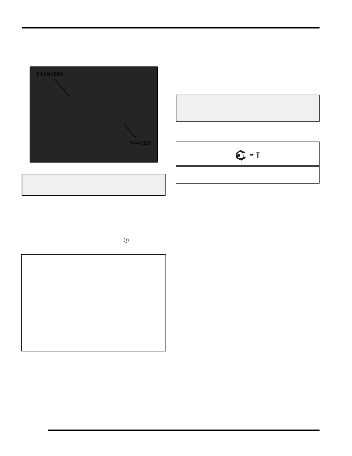
1
ENGINE / COOLING SYSTEM
Oil Pressure Test
1. Attach the Oil Pressure Gauge Adapter (PU-50565)
to the Oil Pressure Gauge (PV-43531).
Oil Pressure Gauge Adapter: PU-50565
Oil Pressure Gauge: PV-43531
2. Remove the seats, engine service panel, and divider
panel heat shield.
3. Clean the area around the main oil gallery plug ,
located in the upper crankcase on the MAG side of
the engine.
4. Remove the crankcase gallery plug
oil pressure adapter.
and insert the
5. Start engine and allow it to reach operating
temperature, monitoring gauge indication.
NOTE: Test results are based on the use of the
recommended engine oil (Polaris PS-4 or PS-4
Extreme Duty) at operating temperature, and may
vary considerably if any other oil is used or if
engine is not up to temperature.
Oil Pressure Specification (Engine Hot):
Minimum @ 1200 RPM: 10 PSI
Minimum @ 7000 RPM: 40 PSI
6. Upon assembly, torque the crankcase gallery plug to
specification.
Crankcase Oil Gallery Plug:
11 ft-lbs (15 Nm)
3.4
9925724 R01 - 2014-2015 RZR XP 1000 / RZR XP4 1000 Service Manual
© Copyright 2014 Polaris Industries Inc.
Page 81

Engine Oil Flow Chart
ENGINE / COOLING SYSTEM
3
9925724 R01 - 2014-2015 RZR XP 1000 / RZR XP4 1000 Service Manual
© Copyright 2014 Polaris Industries Inc.
3.5
Page 82

ENGINE / COOLING SYSTEM
ENGINE SERVICE SPECIFICATIONS
Engine Specifications
CAMSHAFT / CYLINDER HEAD / CYLINDER
ITEM
Camshaft
Cylinder
Cylinder
Head
STANDARD SERVICE LIMIT
Cam Lobe Height - Intake 1.5390 - 1.5429" (39.09 - 39.19 mm) 1.5370" (39.04 mm)
Cam Lobe Height - Exhaust 1.5142 - 1.5181" (38.46 - 38.56 mm) 1.5122" (38.41 mm)
Camshaft Journal O.D. - All
Camshaft Carrier Bore I.D. - All
Camshaft Oil Clearance
Camshaft End Play 0.0040 - 0.0100" (0.101 - 0.254 mm) 0.0157" (0.4 mm)
Cylinder - Surface Warp Limit (cylinder head
surface)
Cylinder Bore - Standard 3.6614 ± 0.0003" (93 mm ± 0.008 mm)
Cylinder Out of Round Limit
Cylinder Taper Limit
Cylinder to Piston Clearance 0.0009 - 0.0019" (0.025 - 0.050 mm)
Cylinder Head - Surface Warp Limit
Cylinder Head - Standard Height 4.717 ± 0.0019" (119.82 ± 0.05 mm)
Valve Lash (Cold) - Intake 0.006 ± 0.002" (0.15 ± 0.05 mm)
Valve Lash (Cold) - Exhaust 0.008 ± 0.002" (0.20 ± 0.05 mm)
0.9036 - 0.9055" (22.954 - 22.999 mm) 0.9033" (22.944 mm)
0.9055 - 0.9063" (23.000 - 23.021 mm) 0.9072" (23.044 mm)
0.0000 - 0.0026" (0.001 - 0.067 mm) 0.0039" (0.1 mm)
-
-
-
-
0.002″ (0.05 mm)
-
0.001″ (0.025 mm)
0.001″ (0.025 mm)
-
0.0039″ (0.1 mm)
-
-
-
Valve
Valve
Guide
Valve Seat
Valve Stem Diameter - Intake
Valve Stem Diameter - Exhaust
Valve Stem Oil Clearance - Intake
Valve Stem Oil Clearance - Exhaust
Valve Stem Overall Length - Intake 3.7704" (95.77 mm)
Valve Stem Overall Length - Exhaust 3.8023" (96.58 mm)
Valve Guide Inner Diameter
Valve Seat - Contacting Width - Intake 0.0393 ± 0.0039" (1.0 ± 0.10 mm) 0.0551" (1.4 mm)
Valve Seat - Contacting Width - Exhaust 0.0590 ± 0.0039" (1.5 ± 0.10 mm) 0.0748" (1.9 mm)
Valve Seat Angles
0.2155 - 0.2161" (5.475 - 5.490 mm)
0.2147 - 0.2153" (5.455 - 5.470 mm)
0.0003 - 0.0015" (0.010 - 0.040 mm)
0.0011 - 0.0023" (0.030 - 0.060 mm)
0.2165 - 0.2171" (5.500 - 5.515 mm)
30.0° ± 1.5°
45.0° ± 0.5°
60.0° ± 1.5°
-
-
-
-
-
-
-
-
3.6
9925724 R01 - 2014-2015 RZR XP 1000 / RZR XP4 1000 Service Manual
© Copyright 2014 Polaris Industries Inc.
Page 83

ENGINE / COOLING SYSTEM
PISTON / RINGS / CONNECTING ROD / CRANKSHAFT / BALANCE SHAFT
ITEM
Piston
Piston Ring
Connecting
Rod
STANDARD SERVICE LIMIT
Standard O.D. - Measured 90° to pin, 0.39
in. (10 mm) up from piston skirt
Piston Pin Bore I.D. (Standard) 0.7877 - 0.7881" (20.009 - 20.018 mm) 0.7893" (20.05 mm)
Piston Pin O.D.
Top Ring 0.010 - 0.014" (0.25 - 0.35 mm) 0.0196" (0.5 mm)
Installed
Gap
Ring to
Groove
Clearance
Connecting Rod Small End I.D. 0.7879 - 0.7885" (20.015 - 20.030 mm) 0.7897" (20.06 mm)
1 - Marking Conn. Rod Big End Bore I.D. 1.7318 - 1.7321" (43.989 - 43.996 mm)
2 - Marking Conn. Rod Big End Bore I.D. 1.7321 - 1.7323" (43.996 - 44.003 mm)
3 - Marking Conn. Rod Big End Bore I.D. 1.7323 - 1.7326" (44.003 - 44.010 mm)
B - Marking
G Marking
Second Ring 0.015 - 0.025" (0.37 - 0.63 mm) 0.028" (0.70 mm)
Oil Control Rails
Top Ring
Second Ring
Main Journal O.D.
Main Journal O.D.
3.6597 ± 0.0003" (92.959 ± 0.008 mm)
0.7873 - 0.7875" (20.000 - 20.005 mm) 0.7866" (19.98 mm)
0.008 - 0.028" (0.20 - 0.70 mm) 0.0354" (0.9 mm)
0.0007 - 0.0023" (0.020 - 0.060 mm) 0.0047" (0.12 mm)
1.6140 - 1.6143" (40.996 - 41.004 mm) 1.6129" (40.970 mm)
1.6137 - 1.6140" (40.988 - 40.995 mm) 1.6129" (40.970 mm)
-
-
-
-
3
Crankshaft
Balance
Shaft
Y - Marking
B - Marking
G Marking
Y - Marking
Crankshaft Runout Limit (PTO and MAG)
Bearing Journal O.D. (Standard) 1.4939 - 1.4946" (37.946 - 37.962 mm) 1.4921" (37.900 mm)
Main Journal O.D.
Rod Journal O.D.
Rod Journal O.D.
Rod Journal O.D.
1.6134 - 1.6137" (40.980 - 40.987 mm) 1.6129" (40.970 mm)
1.6118 - 1.6122" (40.942 - 40.950 mm) 1.6104" (40.906 mm)
1.6115 - 1.6118" (40.934 - 40.941 mm) 1.6104" (40.906 mm)
1.6112 - 1.6115" (40.926 - 40.933 mm) 1.6104" (40.906 mm)
-
Less than 0.001″
(0.025 mm)
9925724 R01 - 2014-2015 RZR XP 1000 / RZR XP4 1000 Service Manual
© Copyright 2014 Polaris Industries Inc.
3.7
Page 84

ENGINE / COOLING SYSTEM
ENGINE DETAIL - TORQUE VALUES / SEQUENCES / ASSEMBLY NOTES
Main Engine Components - Torque Specification and Sequence
3.8
9925724 R01 - 2014-2015 RZR XP 1000 / RZR XP4 1000 Service Manual
© Copyright 2014 Polaris Industries Inc.
Page 85

ENGINE / COOLING SYSTEM
Balance Shaft / Connecting Rods / Crankcase / Crankshaft / Pistons
3
9925724 R01 - 2014-2015 RZR XP 1000 / RZR XP4 1000 Service Manual
© Copyright 2014 Polaris Industries Inc.
3.9
Page 86

ENGINE / COOLING SYSTEM
Cylinder / Oil Cooler / Oil Filter / Oil Pump / Oil Sump / Water Pump
3.10
9925724 R01 - 2014-2015 RZR XP 1000 / RZR XP4 1000 Service Manual
© Copyright 2014 Polaris Industries Inc.
Page 87

ENGINE / COOLING SYSTEM
Camshafts / Cylinder Head / Flywheel / Idler Gears / Stator Cover
3
9925724 R01 - 2014-2015 RZR XP 1000 / RZR XP4 1000 Service Manual
© Copyright 2014 Polaris Industries Inc.
3.11
Page 88

ENGINE / COOLING SYSTEM
Spark Plugs / Starter / Thermostat Housing / Throttle Body / Valve Cover
3.12
9925724 R01 - 2014-2015 RZR XP 1000 / RZR XP4 1000 Service Manual
© Copyright 2014 Polaris Industries Inc.
Page 89

ENGINE COOLING SYSTEM
ENGINE / COOLING SYSTEM
Cooling System Specifications
CONDITION
Room Temperature 68° F (20° C)
Thermostat Open
Fan Off
Fan On
Thermostat Full Open 203° F (95° C)
Engine Temperature
Overheat Indicator
Engine Protection
Ignition Misfire
Engine Protection
Shutdown
ITEM SPECIFICATION
Cooling System Capacity 4.9 qts. (4.6 L)
Pressure Cap Relief
COOLANT TEMP °F (°C)
180° F (82° C)
192° F (89° C)
198° F (92° C)
233° F (112° C)
236° F (113° C)
257° F (125° C)
13 PSI
Cooling System Pressure Test
1. Remove the hood from the front cab.
WARNING
Never remove pressure cap when engine is warm or
hot. The cooling system is under pressure and serious
burns may result.
Allow the engine to cool before servicing.
2. Remove pressure cap and pressure test the cooling
system using a commercially available pressure
tester.
3
Polaris Premium Antifreeze
2871534 - Quart
2871323 - Gallon
Recommended Coolant
Use only high quality antifreeze/coolant mixed with
distilled water in a 50/50 or 60/40 ratio, depending on
freeze protection required in your area.
CAUTION: Using tap water in the cooling system will
lead to a buildup of deposits which may restrict coolant
flow and reduce heat dissipation, resulting in possible
engine damage. Polaris Premium 60/40 Antifreeze/
Coolant is recommended for use in all cooling systems
and comes pre-mixed, ready to use.
3. The system must maintain 10 psi for five minutes or
longer. If pressure loss is evident within five minutes,
check the filler neck, radiator, hoses, clamps and
water pump weep hole for leakage.
9925724 R01 - 2014-2015 RZR XP 1000 / RZR XP4 1000 Service Manual
© Copyright 2014 Polaris Industries Inc.
3.13
Page 90
1
ENGINE / COOLING SYSTEM
Cooling System Pressure Cap Test
1. Remove the hood from the front cab.
WARNING
Never remove pressure cap when engine is warm or
hot. The cooling system is under pressure and serious
burns may result. Allow the engine to cool before
servicing.
2. Remove pressure cap
cap tester (commercially available).
and test using a pressure
Radiator Removal / Installation
1. Remove the hood and front bumper (See Chapter 10
– Hood and Front Body Work, page 10.20and Front
Bumper, page 10.19).
2. Remove the four fasteners that secure the front
bumper support to the main frame.
3. Drain radiator by removing lower radiator hose1. Be
sure to catch and dispose of coolant properly.
3. The pressure cap relief pressure is 13 psi. Replace
cap if it does not meet this specification.
WARNING
The cooling system is under pressure and serious
burns may result.
Allow the engine to cool before servicing.
4. Disconnect cooling fan electrical connector.
5. Remove the upper radiator hose from the radiator.
3.14
9925724 R01 - 2014-2015 RZR XP 1000 / RZR XP4 1000 Service Manual
© Copyright 2014 Polaris Industries Inc.
Page 91

2
3
6
4
7
5
8
1
2
3
ENGINE / COOLING SYSTEM
6. Remove the four upper radiator support fasteners
and disconnect the small radiator bypass hose3.
7. Lift radiator up to disengage it from its lower
mounting points. Tilt top of radiator outward and
remove the radiator from the vehicle.
8. Separate the fan motor assembly from the radiator.
Inspect fan blades for damage.
9. Reverse this procedure for installation. Be sure to
properly fill and bleed cooling system as outlined in
this chapter.
Thermostat Replacement
1. Remove the hood from the front cab.
WARNING
The cooling system is under pressure and serious
burns may result.
Allow the engine to cool before servicing.
2. Remove the pressure cap to relieve any system
pressure (see Chapter 3 – Cooling System Pressure
Cap Test, page 3.14).
3. Drain coolant to a level below the thermostat
housing.
4. Remove upper coolant hose from thermostat
housing
.
3
5. Remove the rear bolt
retaining the thermostat
cover.
6. Remove the cargo box access panel.
7. Using an 8 mm swivel socket and long extension,
remove the front bolt
retaining the thermostat
cover.
Upper Radiator Hose
Lower Radiator Hose
Recovery Bottle
To Radiator Fitting
Fan Motor Assembly
Radiator
3.15
9925724 R01 - 2014-2015 RZR XP 1000 / RZR XP4 1000 Service Manual
© Copyright 2014 Polaris Industries Inc.
Page 92
4
ENGINE / COOLING SYSTEM
8. Lift the cover from the housing and remove the
thermostat.
NOTE: Thermostat has a pop-off relief to allow
the bypass system to operate until thermostat
opens.
9. Install a new thermostat with the bleed hole
positioned closest to the engine.
NOTE: Image shown above is with engine
removed for clarity.
10. Reverse this procedure for installation. Torque
thermostat cover bolts to specification.
Thermostat Cover Bolts:
7 ft-lb (10 Nm)
11. Be sure to properly fill and bleed cooling system as
outlined in this chapter.
3.16
9925724 R01 - 2014-2015 RZR XP 1000 / RZR XP4 1000 Service Manual
© Copyright 2014 Polaris Industries Inc.
Page 93

Cooling System Assembly View
1
6
11
2
7
12
3
8
13
4
9
14
5
10
ENGINE / COOLING SYSTEM
3
Thermostat housing
Water Pump
Engine Hoses
Lower Radiator Hose
Fan Assembly
Filler Neck
Radiator
Pressure Cap
Upper Radiator Hose
Recovery Bottle
Oil Cooler Inlet Hose
Oil Cooler Outlet Hose
Bypass Hose
Water Pump Outlet Hose
3.17
9925724 R01 - 2014-2015 RZR XP 1000 / RZR XP4 1000 Service Manual
© Copyright 2014 Polaris Industries Inc.
Page 94

1
3
ENGINE / COOLING SYSTEM
Cooling System Bleeding Procedure
WARNING
Always wear safety glasses and proper shop clothing
when performing the procedures in this manual. Failing
to do so may lead to possible injury or death.
CAUTION
Use caution when performing these procedures.
Coolant may be hot and may cause
severe injury or burns.
NOTE: If the coolant level is LOW in the radiator, or
if there are leaks in the system, the coolant system
will not draw coolant from the reservoir tank.
1. Allow engine and cooling system to cool down.
6. Open the bleed screw
escape. Close the bleed screw once a steady stream
of coolant begins to drain out.
7. Tighten the bleed screw to specification, top off
coolant and properly install the pressure cap.
to allow any trapped air to
CAUTION
Be sure the engine has cooled and no pressure is built
up in the cooling system before removing the pressure
cap. The coolant may be hot and could cause severe
injury or burns.
2. Remove the hood.
3. Remove the recovery bottle cap
to the MAX line.
4. Remove the pressure cap2and add the necessary
amount of Polaris Premium Antifreeze to the radiator
filler neck.
5. Remove the seats, engine service panel and divider
panel heat shield to access the coolant bleed screw.
and fill the bottle
Coolant Bleed Screw:
89 in-lb (10 Nm)
8. Start the engine and allow it to idle until the coolant
fan has cycled two times.
9. Allow engine and cooling system to completely cool
down (see CAUTION).
10. Remove the pressure cap. Add the necessary
amount of Polaris Premium Antifreeze to the radiator
filler neck.
11. Open the bleed screw to allow any trapped air to
escape. Close the bleed screw once a steady stream
of coolant begins to drain out.
12. Tighten the bleed screw to specification, top off
coolant and properly install the pressure cap.
Coolant Bleed Screw:
89 in-lb (10 Nm)
13. Fill the recovery bottle to the MAX line.
14. Reinstall the hood.
15. Reinstall the seats and engine service panel.
3.18
9925724 R01 - 2014-2015 RZR XP 1000 / RZR XP4 1000 Service Manual
© Copyright 2014 Polaris Industries Inc.
Page 95

1&2
1
2
3
ENGINE / COOLING SYSTEM
Water Pump Removal
1. Allow engine and cooling system to cool down.
CAUTION
Be sure the engine has cooled and no pressure is built
up in the cooling system before removing the pressure
cap. The coolant may be hot and could cause severe
injury or burns.
2. Remove driver’s seat.
3. Disconnect the (-) negative battery cable.
4. Remove all debris and thoroughly clean water pump
area and RH side of engine block.
5. Remove the hood.
6. Remove the pressure cap from the filler neck.
7. Drain cooling system as outlined in this chapter.
8. Elevate the rear of the vehicle off the ground using a
suitable ATV lift and remove the right rear wheel.
9. Remove the right rear shock lower mounting bolt.
Discard the nut. Swing and support right rear shock
rearward to gain access to water pump area.
10. Remove the five coolant hoses that are attached to
the water pump. Note location and routing for
installation. Be sure to catch and dispose of coolant
properly.
11. Remove the three bolts
to engine block. Note different bolt lengths for
installation.
retaining water pump
Water Pump Installation
1. Replace the two sealing O-rings on the water pump
housing.
NOTE: Do not reuse the water pump O-rings.
Always use NEW O-rings each time the water
pump is removed.
2. Lubricate new O-rings
3. Remove the shop towel from the water pump drive
access hole in the engine block.
4. Clean the O-ring sealing surface
block using a clean shop towel.
with fresh engine oil.
in the engine
3
5. Use a shop light to illuminate the water pump drive
access hole in engine crankcase and note
orientation of the water pump drive slot
12. Remove water pump from engine by gently twisting
and rocking the water pump housing while pulling
outward.
13. Maneuver water pump downward and remove it
through the access hole in the skid plate.
14. Plug the water pump drive access hole in the engine
block with a clean shop towel.
.
3.19
9925724 R01 - 2014-2015 RZR XP 1000 / RZR XP4 1000 Service Manual
© Copyright 2014 Polaris Industries Inc.
Page 96

4
5&6
7–10
ENGINE / COOLING SYSTEM
6. Rotate water pump drive tab
so it matches the
angle of the drive slot in the engine.
CAUTION
The water pump drive tab and slot must be aligned
properly during installation. Severe engine or water
pump damage will occur if the tab and slot are not in
alignment during water pump installation.
7. Maneuver water pump up through the access hole in
the skid plate on the RH side of the vehicle.
8. Slide water pump into engine crankcase.
9. Be sure water pump is fully seated and the drive tab
and slot are properly engaged.
10. Install the three water pump mounting bolts
and torque to specification.
NOTE: Install different bolt lengths as shown.
Water Pump Mounting Bolts:
7 ft-lb (10 Nm)
(Apply Loctite® 204™ to bolt threads)
11. Install the four coolant hoses
that attach to the
water pump. Be sure orientation and routing are
correct.
12. Install the right rear lower shock bolt and new nut.
Torque mounting bolt to specification.
Rear Shock Mounting Bolt:
70 ft-lbs (95 Nm)
3.20
9925724 R01 - 2014-2015 RZR XP 1000 / RZR XP4 1000 Service Manual
© Copyright 2014 Polaris Industries Inc.
Page 97
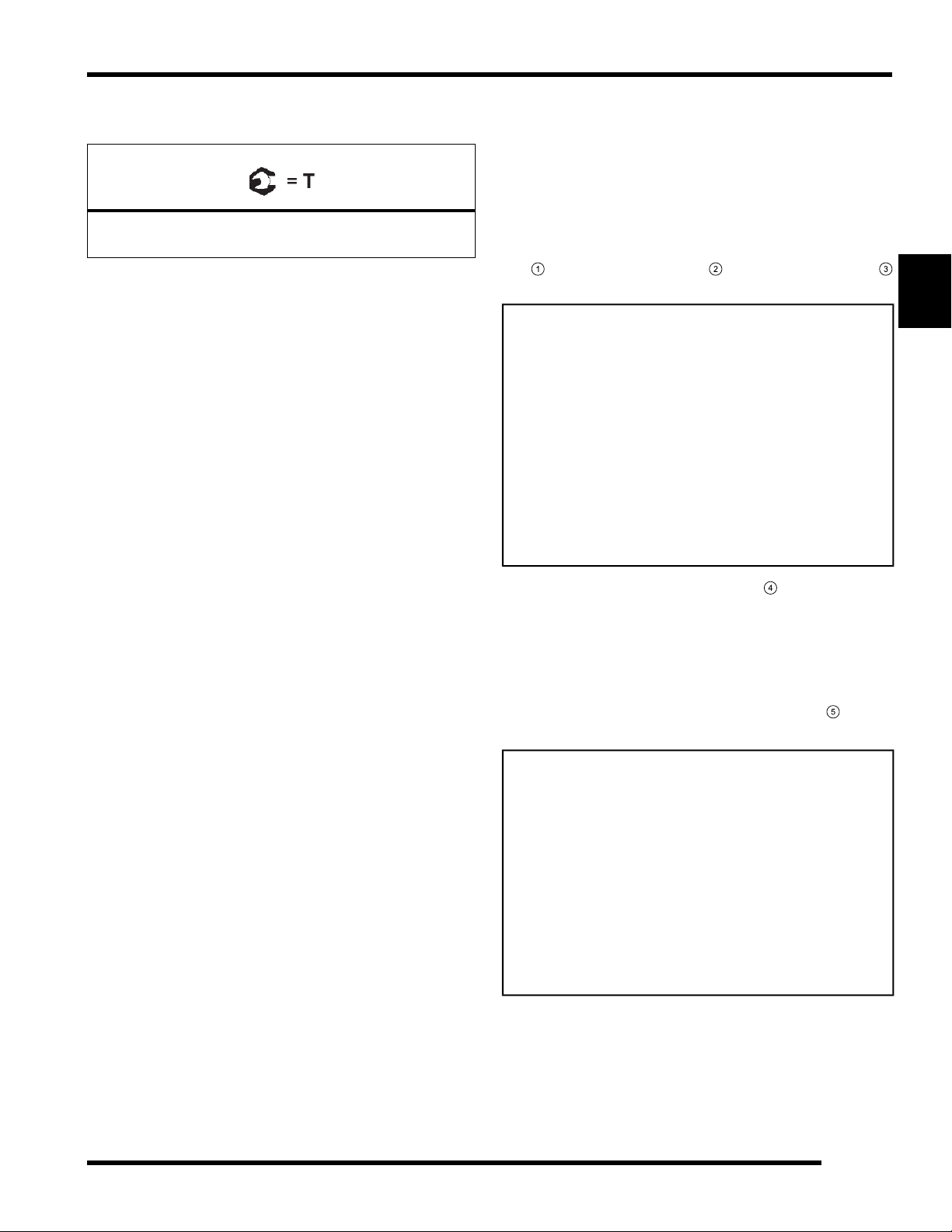
1
3
4
5
ENGINE / COOLING SYSTEM
13. Install the right rear wheel. Torque wheel nuts to
specification.
Wheel Nuts:
120 ft-lbs (163 Nm)
14. Connect the (-) negative battery cable.
15. Fill and bleed cooling system as outlined in this
chapter.
16. Install the hood, engine service panel and seats.
Water Pump Service
NOTE: The water pump cover gasket can be
replaced while the water pump housing is still
installed in the engine.
1. Remove water pump assembly as outlined in this
chapter.
2. Remove the three bolts retaining water pump cover
to water pump housing2. Discard cover gasket
.
3
3. Place the water pump drive tab
vertically into a
soft jaw vice.
4. Remove the bolt and washer retaining the water
pump impeller to the shaft. Inspect the impeller veins
and water pump housing for damage. Replace if
needed.
NOTE: The water pump impeller bolt
is left
hand thread (reverse thread).
5. Remove impeller from water pump shaft.
6. Using an appropriate arbor press, properly support
the water pump housing and press out the water
pump shaft from the impeller side.
3.21
9925724 R01 - 2014-2015 RZR XP 1000 / RZR XP4 1000 Service Manual
© Copyright 2014 Polaris Industries Inc.
Page 98

6
1
3
ENGINE / COOLING SYSTEM
7. Extract the mechanical seal and the oil seal from the
water pump housing.
NOTE: A 5/32" (4 mm) diameter punch
will fit
in the lubrication slot to aid in the removal of the
oil seal. Be sure not to damage the water pump
shaft bearing surface.
8. Inspect the water pump shaft bore for excessive
wear or damage. Replace water pump housing
assembly if necessary.
9. Clean and inspect water pump shaft for excessive
wear or damage. Replace water pump housing
assembly if necessary, as shaft can not be
purchased separately.
10. Thoroughly clean mechanical seal and oil seal
bores.
11. Install a NEW oil seal into the water pump housing
until fully seated.
12. Fully install the water pump shaft and two washers
into the housing.
13. Place water pump drive tab vertically into soft jaw
vice as previously shown in this procedure.
14. Install a NEW mechanical seal into the water pump
housing using special tool PU-50564. Press the new
mechanical seal in until it is flush with the water
pump housing.
15. Rotate water pump shaft after seal installation to
verify free movement.
16. Place impeller onto the water pump shaft.
17. Apply Loctite
®
204™to the threads of the impeller
bolt. Install washer and impeller bolt and torque to
specification.
Water Pump Impeller Bolt:
7 ft-lb (10 Nm)
(Apply Loctite® 204™ to bolt threads)
18. Clean cover
19. Install a new water pump cover gasket
and housing gasket surfaces2.
.
3.22
9925724 R01 - 2014-2015 RZR XP 1000 / RZR XP4 1000 Service Manual
© Copyright 2014 Polaris Industries Inc.
Page 99

20. Install the water pump cover and three retaining bolts
8
9
13
17
10
14
18
11
15
19
12
16
. Torque bolts in sequence to specification.
ENGINE / COOLING SYSTEM
Water Pump Cover Bolts:
7 ft-lb (10 Nm)
(Apply Loctite® 204™ to bolt threads)
21. Install two new water pump (O-rings) and lubricate
them with fresh engine oil.
22. Install water pump assembly into engine as shown in
the “Water Pump Installation” procedure.
3
Bolt
Loctite 204
Mechanical Seal
O-Rings
Washers
Drive Tab
Water Pump Shaft
Water Pump Housing
Oil Seal
Impeller
Washer
3.23
9925724 R01 - 2014-2015 RZR XP 1000 / RZR XP4 1000 Service Manual
© Copyright 2014 Polaris Industries Inc.
Page 100

ENGINE / COOLING SYSTEM
ENGINE SERVICE
Accessible Engine Components
The following components can be serviced or removed
with the engine installed:
• Camshaft(s)
• Camshaft Sprocket(s)
• Cylinder Head
• Flywheel
• Oil Cooler
• Starter Motor / Idler Gear Asm
• Stator (Alternator)
• Thermostat
• Valve Cover
• Water Pump
The following components require engine removal for
service:
• Camshaft Timing Chain
• Connecting Rod(s)
• Counterbalance Shaft / Bearings
• Crankcase
• Crankshaft / Main Bearings
• Crankshaft Seal (PTO)
• Cylinder
• Oil Pump / Oil Pump Sprocket or Chain
• Piston / Rings
Top-End Service (Engine in Chassis)
Some top-end engine components can be serviced while
the engine is mounted in the chassis.
To service the top-end of the engine refer to Valve
Clearance Inspection, page 2.20, which provides
detailed steps to access the valve cover.
Engine Removal
NOTE: Some engine repair procedures can be
performed without removing the engine assembly
from the vehicle. Refer to Accessible Engine
Components, page 3.24 for further information.
The use of an overhead or portable engine hoist is
the only recommended method for removing and
installing the engine.
Have an assistant help guide the engine in and out of
the vehicle while using an engine hoist to prevent
personal injury or damage to vehicle components.
WARNING
Always wear safety glasses and proper shop clothing
when performing the procedures in this Service
Manual. Failing to do so may lead to possible injury.
1. If vehicle was recently operated, allow it to cool down
before attempting to perform any work.
2. Thoroughly clean the engine and chassis.
3. Drain the engine oil and coolant prior to engine
removal (See Chapter 2 – Coolant Drain / Fill, page
2.29).
4. Remove the seats.
5. Disconnect the (-) negative battery cable from the
battery.
6. Remove the rear bumper and cargo box (see
Chapter 10 – Cargo Box Assembly Removal, page
10.22).
7. Remove the air box assembly.
8. Elevate the rear of the vehicle off the ground using a
suitable lift and remove the left rear wheel.
3.24
WARNING
Use care when supporting vehicle so that it does not tip
or fall.
Serious injury may occur if vehicle tips or falls.
9925724 R01 - 2014-2015 RZR XP 1000 / RZR XP4 1000 Service Manual
© Copyright 2014 Polaris Industries Inc.
 Loading...