

Page 1

GENERAL INFORMATION
CHAPTER 1
GENERAL INFORMATION
MODEL INFORMATION . . . . . . . . . . . . . . . . . . . . . . . . . . . . . . . . . . . . . . . . . . . . . . . . . . 1.2
MODEL IDENTIFICATION . . . . . . . . . . . . . . . . . . . . . . . . . . . . . . . . . . . . . . . . . . . . . . . .1.2
ENGINE DESIGNATION NUMBER . . . . . . . . . . . . . . . . . . . . . . . . . . . . . . . . . . . . . . . . .1.2
VIN IDENTIFICATION . . . . . . . . . . . . . . . . . . . . . . . . . . . . . . . . . . . . . . . . . . . . . . . . . . .1.2
ENGINE SERIAL NUMBER LOCATION . . . . . . . . . . . . . . . . . . . . . . . . . . . . . . . . . . . . .1.2
UNIT SERIAL NUMBER (VIN) LOCATION . . . . . . . . . . . . . . . . . . . . . . . . . . . . . . . . . . .1.3
VEHICLE INFORMATION . . . . . . . . . . . . . . . . . . . . . . . . . . . . . . . . . . . . . . . . . . . . . . . . . 1.4
PUBLICATION NUMBERS. . . . . . . . . . . . . . . . . . . . . . . . . . . . . . . . . . . . . . . . . . . . . . . .1.4
PAINT CODES . . . . . . . . . . . . . . . . . . . . . . . . . . . . . . . . . . . . . . . . . . . . . . . . . . . . . . . . .1.4
REPLACEMENT KEYS . . . . . . . . . . . . . . . . . . . . . . . . . . . . . . . . . . . . . . . . . . . . . . . . . .1.4
SPECIAL TOOLS . . . . . . . . . . . . . . . . . . . . . . . . . . . . . . . . . . . . . . . . . . . . . . . . . . . . . . . 1.4
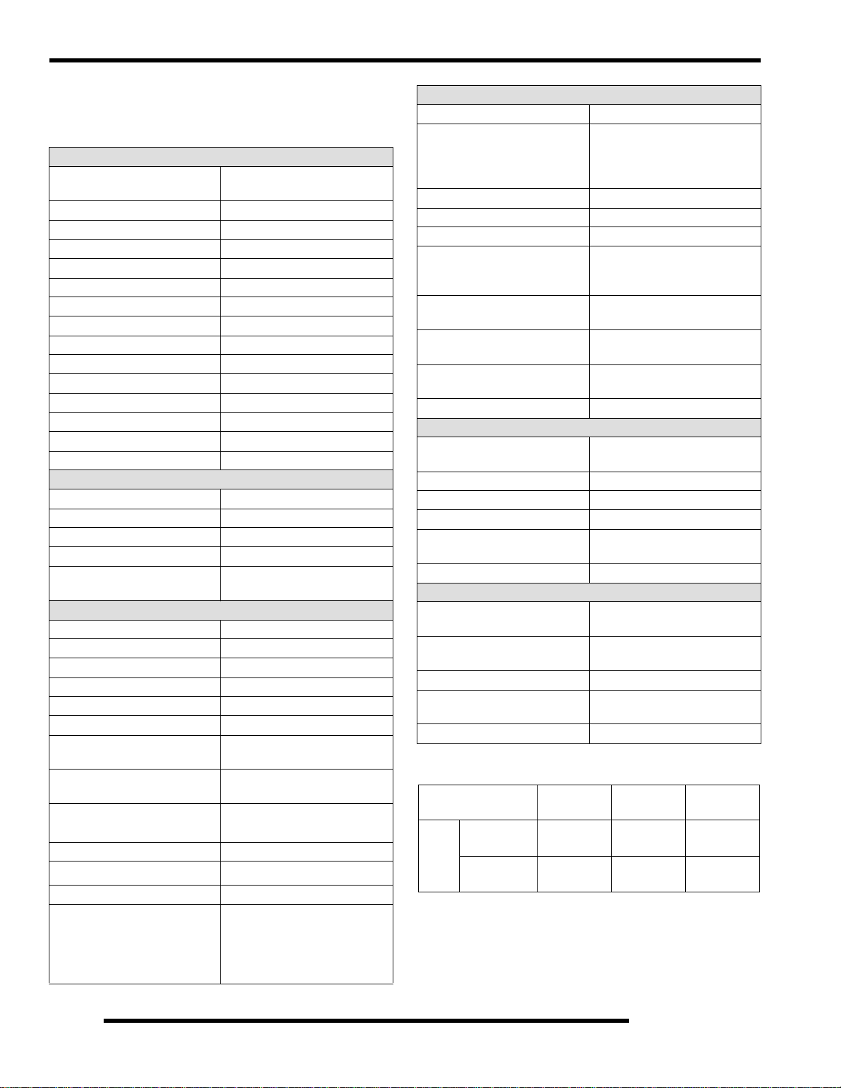
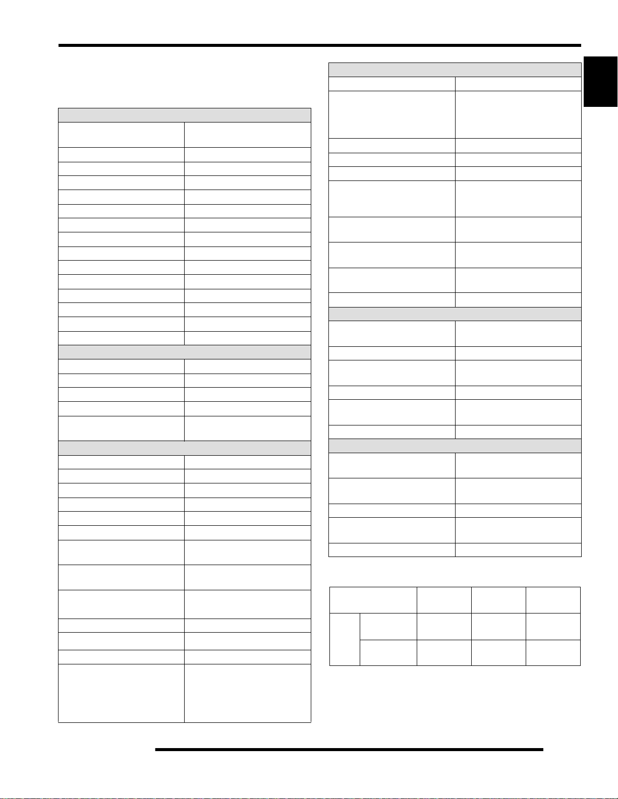
GENERAL SPECIFICATIONS. . . . . . . . . . . . . . . . . . . . . . . . . . . . . . . . . . . . . . . . . . . . . . 1.5
GENERAL: 2009 RANGER RZR . . . . . . . . . . . . . . . . . . . . . . . . . . . . . . . . . . . . . . . . . . .1.5
GENERAL: 2009 RANGER RZR “S” . . . . . . . . . . . . . . . . . . . . . . . . . . . . . . . . . . . . . . . .1.5
DETAILED: 2009 RANGER RZR . . . . . . . . . . . . . . . . . . . . . . . . . . . . . . . . . . . . . . . . . . .1.6
DETAILED: 2009 RANGER RZR “S” . . . . . . . . . . . . . . . . . . . . . . . . . . . . . . . . . . . . . . . .1.7
MISC. SPECIFICATIONS AND CHARTS . . . . . . . . . . . . . . . . . . . . . . . . . . . . . . . . . . . . . 1.8
CONVERSION TABLE. . . . . . . . . . . . . . . . . . . . . . . . . . . . . . . . . . . . . . . . . . . . . . . . . . .1.8
STANDARD TORQUE SPECIFICATIONS. . . . . . . . . . . . . . . . . . . . . . . . . . . . . . . . . . . .1.9
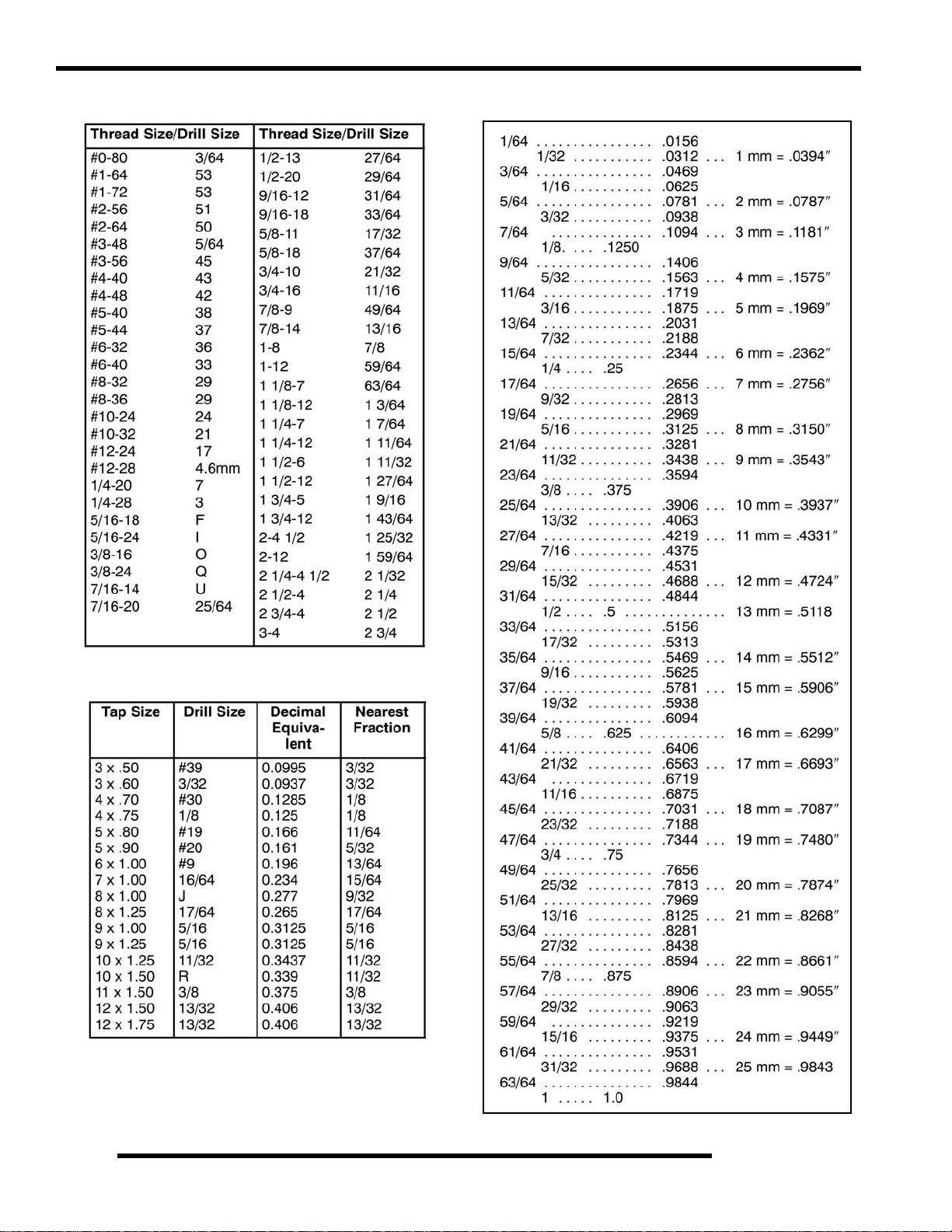
SAE TAP / DRILL SIZES . . . . . . . . . . . . . . . . . . . . . . . . . . . . . . . . . . . . . . . . . . . . . . . .1.10
METRIC TAP / DRILL SIZES . . . . . . . . . . . . . . . . . . . . . . . . . . . . . . . . . . . . . . . . . . . . .1.10
DECIMAL EQUIVALENTS . . . . . . . . . . . . . . . . . . . . . . . . . . . . . . . . . . . . . . . . . . . . . . .1.10
GLOSSARY OF TERMS. . . . . . . . . . . . . . . . . . . . . . . . . . . . . . . . . . . . . . . . . . . . . . . . .1.11
1
1.1
Page 2
GENERAL INFORMATION
MODEL INFORMATION
Model Identification
The machine model number must be used with any correspondence regarding warranty or service.
Machine Model Number Identification
R 0 9 V H 7 6 A D
Model Year
Designation
Basic Chassis
Designation
Engine Designation Number
EH076OLE022........................................................................Twin Cylinder, Liquid Cooled, OHV 4 Stroke, Electric Start (RZR)
EH076OLE072.................................................................Twin Cylinder, Liquid Cooled, OHV 4 Stroke, Electric Start (RZR “S”)
VIN Identification
World
Mfg. ID
1 2 3 4 5 6 7 8 9 10 11 12 13 14 15 16 17
4 X A V H 7 6 A * 9 P 0 0 0 0 0 0
Vehicle Description
}
}
}
}
}
Emissions &
Model Option
Engine Designation
Vehicle Identifier
Model
Year
Check Digit
Plant No.
Individual Serial No.
* This could be either
a number or a letter
Body Style
Powertrain
Engine
Emissions
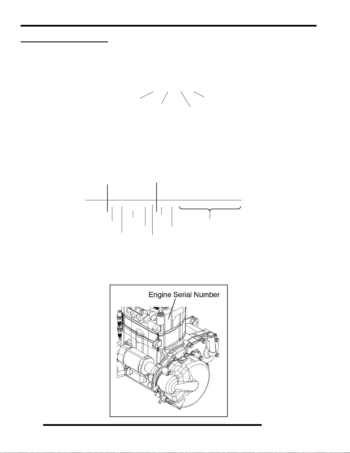
Engine Serial Number Location
Whenever corresponding about an engine, be sure to refer to the engine model number and serial number. This information can be
found on the sticker applied to the cylinder head on the side of engine.
1.2
Page 3
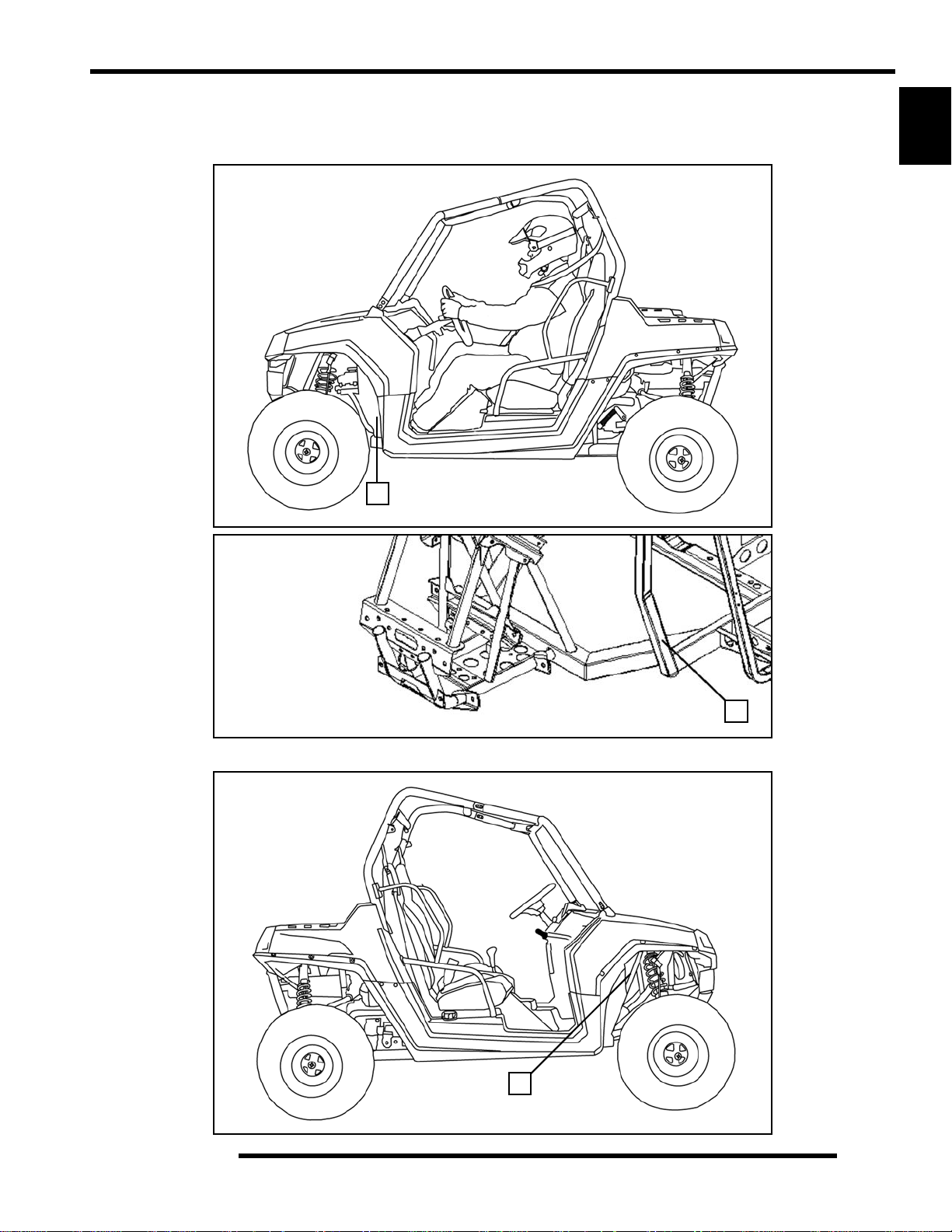
Unit Serial Number (VIN) Location
GENERAL INFORMATION
The machine model number and serial number (VIN) are important for vehicle identification. The VIN number (A) is stamped on
a portion of the front left frame rail close to the left front wheel.
A
1
A
The VIN and model number are also located on a decal (B) attached to the frame support accessible through the front right wheel well.
B
1.3
Page 4
GENERAL INFORMATION
VEHICLE INFORMATION
Publication Numbers
Model Model No. Owner’s Manual PN Parts Manual PN
2009 RANGER RZR R08VH76AD, AG, AH, AO 9921878 9921879
2009 RANGER RZR “S” R08VH76AX 9921878 9922130
NOTE: When ordering se rvic e part s be sure to use the correct parts manual.
NOTE: Polaris factory publications can be found at www.polarisindustries.com or purchased from
www.purepolaris.com.
Paint Codes
Painted Part Color Description Polaris Number
Frame / Bumpers / Racks Gloss Black P-067
Frame / Bumpers / Racks Matte Black P-458
Plastic - Hood / Dash / Fenders Indy Red P-293
Plastic - Hood / Dash / Fenders Sage Brush Green Metallic P-498
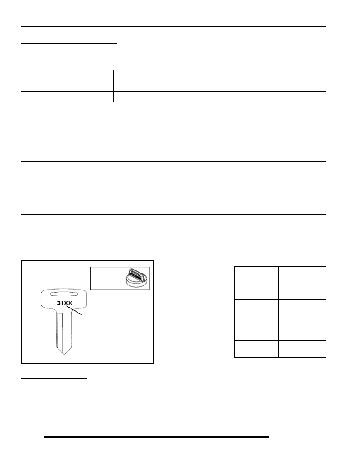
Replacement Keys
Replacement keys can be made from the original key. To identify which series the key is, take the first two digits on the original
key and refer to the chart to the right for the proper part number.
KEY COVER
P/N 5533534
Key Series
Number
Series# Part Number
20 4010278
21 4010278
22 4010321
23 4010321
27 4010321
28 4010321
31 4110141
32 4110148
67 4010278
68 4010278
SPECIAL TOOLS
Special tools may be required while servicing this vehicle. Some of the tools listed or depicted are mandatory, while other tools
maybe substituted with a similar tool, if available. Polaris recommends the use of Polaris Special Tools when servicing any Polaris
product. Dealers may order special tools through Polaris’ official tool supplier, SPX Corporation, by phone at 1-800-328-6657 or
on-line at http://polaris.spx.com/
.
1.4
Page 5
GENERAL SPECIFICATIONS
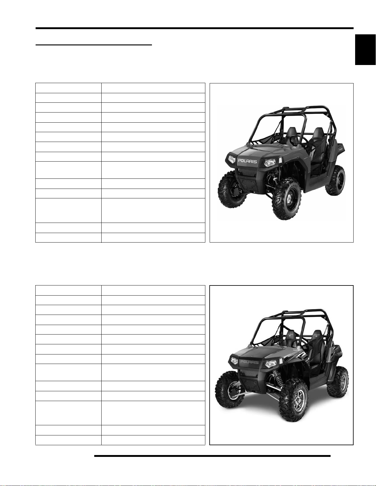
MODEL: 2009 RANGER RZR
MODEL NUMBER: R09VH76AD, AG, AH, AO
ENGINE MODEL: EH076OLE022
Category Dimension / Capacity
Length 102 in. / 259 cm
Width 50 in. / 127 cm
Height 68.5 in. / 174 cm
Wheel Base 77 in. / 196 cm
Ground Clearance 10 in. / 25.4 cm
Dry Weight 945 lbs. / 429 kg
Gross Vehicle Weight 1727 lbs. / 783 kg
Front Storage
Capacity
Cargo Box Dimension 42 in. x 22 in. / 107 cm x 56 cm
Cargo Box Capacity 300 lbs. / 136 kg
Maximum Weight
Capacity (Payload)
Hitch Towing Capacity 1500 lbs. / 680 kg
Hitch Tongue Capacity 150 lbs. / 68 kg
(Includes rider(s), cargo, accessories
25 lbs. / 11.3 kg
740 lbs. / 336.4 kg
and trailer tongue weight)
GENERAL INFORMATION
1
MODEL: 2009 RANGER RZR “S”
MODEL NUMBER: R09VH76AX
ENGINE MODEL: EH076OLE072
Category Dimension / Capacity
Length 106 in. / 269 cm
Width 60.5 in. / 154 cm
Height 70.5 in. / 179 cm
Wheel Base 77 in. / 196 cm
Ground Clearance 12 in. / 30.5 cm
Dry Weight 1000 lbs. / 454 kg
Gross Vehicle Weight 1782 lbs. / 808 kg
Front Storage
Capacity
Cargo Box Dimension 42 in. x 22 in. / 107 cm x 56 cm
Cargo Box Capacity 300 lbs. / 136 kg
Maximum Weight
Capacity (Payload)
Hitch Towing Capacity 1500 lbs. / 680 kg
Hitch Tongue Capacity 150 lbs. / 68 kg
(Includes rider(s), cargo, accessories
25 lbs. / 11.3 kg
740 lbs. / 336.4 kg
and trailer tongue weight)
1.5
Page 6
GENERAL INFORMATION
MODEL: 2009 RANGER RZR
MODEL NUMBER: R09VH76AD, AG, AH, AO
ENGINE MODEL: EH076OLE022
Engine
Platform
Engine Model Number EH076OLE022
Engine Displacement 760cc
Number of Cylinders 2
Bore & Stroke (mm) 80 x 76.5 mm
Compression Ratio 9.78:1
Compression Pressure 150-170 psi
Engine Idle Speed 1150 ± 100 RPM
Engine Max Operating RPM 6500 ± 200 RPM
Lubrication Pressurized Wet Sump
Oil Requirements PS-4 PLUS / 2W-50 Synthetic
Oil Capacity 2 qts. / 1.9 liters
Coolant Capacity 4.8 qts. / 4.5 liters
Overheat Warning Instrument Cluster Indicator
Exhaust System Single Headpipe / Single Silencer
Fuel System Type Bosch Electronic Fuel Injection
Fuel Delivery Electronic Fuel Pump (in tank)
Fuel Pressure 39 psi
Fuel Filters See Chapter 4
Fuel Capacity / Requirement
Alternator Max Output 500 Watts @ 3000 RPM
Lights: Main Headlights 2 - Single Beam 55 W / Halogen
Tail / Brake 2 - 5 Watts / 2 - 5 Watts
Starting System Electric Start
Ignition System Bosch EFI (ECU Contr olled)
Ignition Timing 13° BTDC @ 1200 RPM
Spark plug / Gap
Battery
Instrument Type
DC Outlet Standard 12 V
Relays
Circuit Breaker Fan Motor: 20 Amp
Fuses
Polaris Domestic Twin Cylinder,
Liquid Cooled, 4-Stroke
Fuel System
7 gal. (26.5 liters)
87 Octane (minimum)
Electrical
Champion RC7YC3 /
.035 in. (0.9 mm)
Yuasa YTX20HL /
18 Amp Hr. / 310 CCA / 12 Volt
Analog Speedometer
with Multifunction LCD
EFI / Fan
Chassis: 20 Amp
EFI: 15 Amp
Lights: 15 Amp
Accessory: 15 Amp
Speedo/ECU: 5 Amp
Drivetrain
Transmission Type Polaris Automatic PVT
Gear Ratio: Front / Rear
High
Low
Rev
Drive Ratio - Front 3.82:1
Drive Ratio - Final 3.70:1
Shift Type In Line Shift - H / L / N / R / P
Polaris Demand Drive LT
Front Gearcase Oil Requirements
Transmission Oil Requirements
Main Gearcase
Transmission Oil Requirements
Transfer Case
Rear Gearcase Oil Requirements
Belt 3211113
Steering / Suspension
Front Suspension
Front Travel 9 in. / 23 cm
Rear Suspension Rolled IRS w/Anti-Sway Bar
Rear Travel 9.5 in. / 24 cm
Shock Preload Adjustment
Front / Rear
Toe Out 1/8-1/4 in. / 3-6.35 mm
Wheels / Brakes
Front Wheel Size
Front Tire Size
Rear Wheel Size
Rear Tire Size
Tire Air Pressure - Front / Rear 8 psi (55 kPa)
Brake - Front / Rear
Brake Fluid DOT 4
Polaris High Performance AGL
Polaris High Performance AGL
Independent Dual A-arm
Foot Actuated - 4 Wheel
3.14:1
8.71:1
5.94:1
Premium Fluid
6.75 oz. (200 ml)
24 oz. (710 ml)
14 oz. (414 ml)
Polaris Premium ADF
26 oz. (769 ml)
w/Anti-Sway Bar
Cam Adjustment
12 x 6 / 10 gauge
Maxxis / 25 x 8 R12
12 x 8 / 10 gauge
Maxxis / 25 x 10 R12
Hydraulic Disc
CLUTCH CHART
Altitude Shift Weight Drive Spring
Meters
(Feet)
0-1500
(0-5000)
1500-3700
(5000 - 12000)
20-62
(5631700)
20-58
(5631216)
Blue / Red
(7043199)
Blue / Red
(7043199)
Driven
Spring
Red or Yellow
(3234452)
Red or Yellow
(3234452)
1.6
Page 7
GENERAL INFORMATION
MODEL: 2009 RANGER RZR “S”
MODEL NUMBER: R09VH76AX
ENGINE MODEL: EH076OLE072
Engine
Platform
Engine Model Number EH076OLE072
Engine Displacement 760cc HO
Number of Cylinders 2
Bore & Stroke (mm) 80 x 76.5 mm
Compression Ratio 11:1
Compression Pressure 165-185 psi
Engine Idle Speed 1250 ± 100 RPM
Engine Max Operating RPM 6600 ± 200 RPM
Lubrication Pressurized Wet Sump
Oil Requirements PS-4 PLUS / 2W-50 Synthetic
Oil Capacity 2 qts. / 1.9 liters
Coolant Capacity 4.8 qts. / 4.5 liters
Overheat Warning Instrument Cluster Indicator
Exhaust System Dual Headpipe / Single Silencer
Fuel System Type Bosch Electronic Fuel Injection
Fuel Delivery Electronic Fuel Pump (in tank)
Fuel Pressure 39 psi
Fuel Filters See Chapter 4
Fuel Capacity / Requirement
Alternator Max Output 500 Watts @ 3000 RPM
Lights: Main Headlights 2 - Single Beam 55 W / Halogen
Tail / Brake 2 - 5 Watts / 2 - 5 Watts
Starting System Electric Start
Ignition System Bosch EFI (ECU Controlled)
Ignition Timing 13° BTDC @ 1200 RPM
Spark plug / Gap
Battery
Instrument Type
DC Outlet Standard 12 V
Relays
Circuit Breaker Fan Motor: 20 Amp
Fuses
Polaris Domestic Twin Cylinder,
Liquid Cooled, 4-Stroke
Fuel System
7 gal. (26.5 liters)
87 Octane (minimum)
Electrical
Champion RC7YC3 /
.035 in. (0.9 mm)
Yuasa YTX20HL /
18 Amp Hr. / 310 CCA / 12 Volt
Analog Speedometer
with Multifunction LCD
EFI / Fan
Chassis: 20 Amp
EFI: 15 Amp
Lights: 15 Amp
Accessory: 15 Amp
Speedo/ECU: 5 Amp
Drivetrain
Transmission Type Polaris Automatic PVT
Gear Ratio: Front / Rear
High
Low
Rev
Drive Ratio - Front 3.82:1
Drive Ratio - Final 3.70:1
Shift Type In Line Shift - H / L / N / R / P
Polaris Demand Drive LT
Front Gearcase Oil Requirements
Transmission Oil Requirements
Main Gearcase
Transmission Oil Requirements
Transfer Case
Rear Gearcase Oil Requirements
Belt 3211130
Steering / Suspension
Front Suspension / Shock
Front Travel 12 in. / 30.5 cm
Rear Suspension / Shock
Rear Travel 12 in. / 30.5 cm
Shock Preload Adjustment
Front / Rear
Toe Out 1/8-1/4 in. / 3-6.35 mm
Wheels / Brakes
Front Wheel Size
Front Tire Size
Rear Wheel Size
Rear Tire Size
Tire Air Pressure - Front / Rear 8 psi (55 kPa)
Brake - Front / Rear
Brake Fluid DOT 4
Polaris High Performance AGL
Polaris High Performance AGL
Independent Dual A-arm
Rolled IRS w/Anti-Sway Bar
Threaded Shock Adjustment
12 x 6 / Cast Aluminum
Maxxis Bighorn / 26 x 9 R12
12 x 8 / Cast Aluminum
Maxxis Bighorn / 26 x 12 R12
Foot Actuated - 4 Wheel
3.14:1
8.71:1
5.94:1
Premium Fluid
6.75 oz. (200 ml)
24 oz. (710 ml)
14 oz. (414 ml)
Polaris Premium ADF
26 oz. (769 ml)
FOX™ PODIUM X
FOX™ PODIUM X
with Spanner Wrench
Hydraulic Disc
CLUTCH CHART
Altitude Shift Weight Drive Spring
Meters
(Feet)
0-1500
(0-5000)
1500-3700
(5000 - 12000)
21-74
(5632117)
21-70
(5632127)
Red / White
(7043349)
Red / White
(7043349)
1
Driven
Spring
Red or Yellow
(3234452)
Red or Yellow
(3234452)
1.7
Page 8
GENERAL INFORMATION
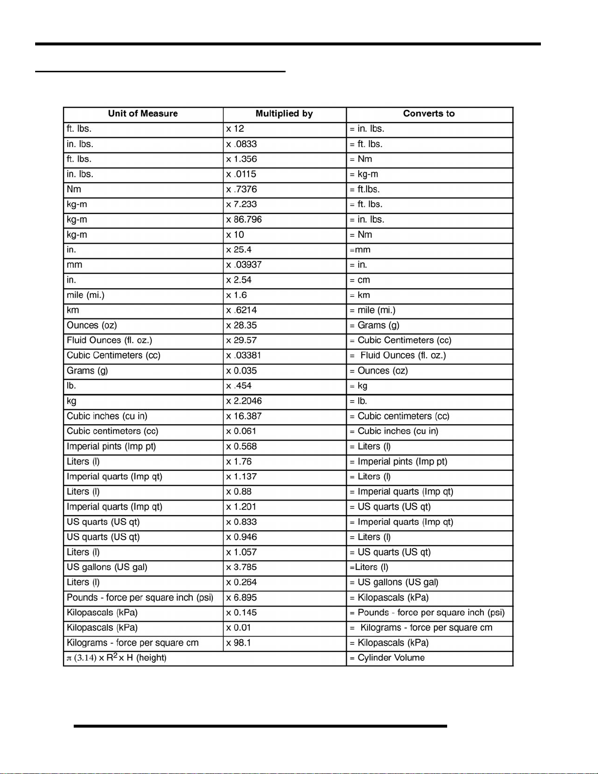
MISC. SPECIFICATIONS AND CHARTS
Conversion Table
1.8
°C to °F:
9/5
(°C + 32) = °F °F to °C:
5/9
(°F - 32) = °C
Page 9
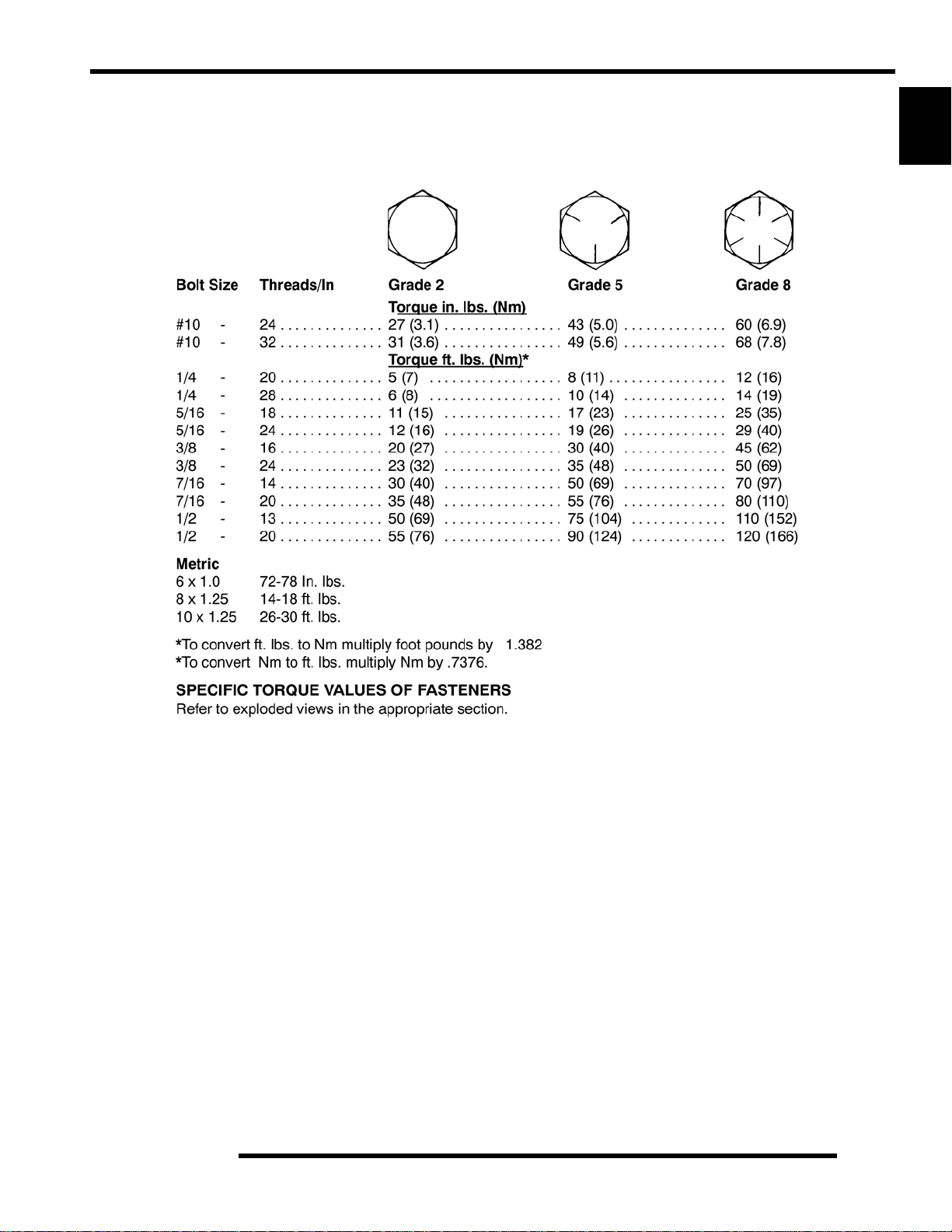
Standard Torque Specifications
GENERAL INFORMATION
The following torque specifications are to be used only as a general guideline. There are exceptions in the steering, suspension, and
engine areas. Always consult the exploded views or each manual section for torque values of fasteners before using standard torque.
1
1.9
Page 10
GENERAL INFORMATION
SAE Tap / Drill Sizes
Decimal Equivalents
Metric Tap / Drill Sizes
1.10
Page 11

GENERAL INFORMATION
Glossary of Terms
ABDC: After bottom dead center.
ACV: Alternating current voltage.
Alternator: Electrical generator producing voltage alternating current.
ATDC: After top dead center.
BBDC: Before bottom dead center.
BDC: Bottom dead center.
BTDC: Before top dead center.
CC: Cubic centimeters.
Center Distance: Distance between center of crankshaft and center of driven clutch shaft.
Chain Pitch: Distance between chain link pins (No. 35 = 3/8" or 1 cm). Polaris measures chain length in number of pitches.
CI: Cubic inches.
Clutch Buttons: Plastic bushings which aid rotation of the movable sheave in the drive and driven clutch.
Clutch Offset: Drive and driven clutches are offset so that drive belt will stay nearly straight as it moves along the clutch face.
Clutch Weights: Three levers in the drive clutch which relative to their weight, profile and engine RPM cause the drive clutch to
close and grip the drive belt.
Crankshaft Run-Out: Run-out or "bend" of crankshaft measured with a dial indicator while crankshaft is supported between centers
on V blocks or resting in crankcase. Measure at various points especially at PTO.
DCV: Direct current voltage
CVT: Centrifugal Variable Transmission (Drive Clutch System)
DCV: Direct current voltage.
Dial Bore Gauge: A cylinder measuring instrument which uses a dial indicator. Good for showing taper and out-of-round in the
cylinder bore.
Electrical Open: Open circuit. An electrical circuit which isn't complete.
Electrical Short: Short circuit. An electrical circuit which is completed before the current reaches the intended load. (i.e. a bare wire
touching the chassis).
End Seals: Rubber seals at each end of the crankshaft.
Engagement RPM: Engine RPM at which the drive clutch engages to make contact with the drive belt.
ft.: Foot/feet.
Foot Pound: Ft. lb. A force of one pound at the end of a lever one foot in length, applied in a rotational direction.
g: Gram. Unit of weight in the metric system.
gal.: Gallon.
ID: Inside diameter.
in.: Inch/inches.
Inch Pound: In. lb. 12 in. lbs. = 1 ft. lb.
kg/cm²: Kilograms per square centimeter.
kg-m: Kilogram meters.
Kilogram/meter: A force of one kilogram at the end of a lever one meter in length, applied in a rotational direction.
l or ltr: Liter.
lbs/in²: Pounds per square inch.
Left or Right Side: Always referred to based on normal operating position of the driver.
m: Meter/meters.
Mag: Magneto.
Magnetic Induction: As a conductor (coil) is moved through a magnetic field, a voltage will be generated in the wind ings.
Mechanical energy is converted to electrical energy in the stator.
mi.: Mile/miles.
mm: Millimeter. Unit of length in the metric system. 1 mm = approximately .040".
Nm: Newton meters.
OD: Outside diameter.
Ohm: The unit of electrical resistance opposing current flow.
oz.: Ounce/ounces.
Piston Clearance: Total distance between piston and cylinder wall.
psi.: Pounds per square inch.
PTO: Power take off.
PVT: Polaris Variable Transmission (Drive Clutch system)
qt.: Quart/quarts.
Regulator: Voltage regulator. Regulates battery charging system output at approx. 14.5 DCV as engine RPM increases.
Reservoir Tank: The fill tank in the liquid cooling system.
Resistance: In the mechanical sense, friction or load. In the electrical sense, ohms, resulting in energy conversion to heat.
RPM: Revolutions per minute.
Seized Piston: Galling of the sides of a piston. Usually there is a transfer of aluminum from the piston onto the cylinder wall.
Possible causes: 1) improper lubrication; 2) excessive temperatures; 3) insufficient piston clearance; 4) stuck piston rings.
Stator Plate: The plate mounted under the flywheel supporting the battery charging coils.
TDC: Top dead center. Piston's most outward travel from crankshaft.
Volt: The unit of measure for electrical pressure of electromotive force. Measured by a voltmeter in parallel with the circuit.
Watt: Unit of electrical power. Watts = amperes x volts.
WOT: Wide open throttle.
1
1.11
Page 12

GENERAL INFORMATION
NOTES
1.12
Page 13

MAINTENANCE
CHAPTER 2
MAINTENANCE
PERIODIC MAINTENANCE CHART. . . . . . . . . . . . . . . . . . . . . . . . . . . . . . . . . . . . . . . . . 2.3
PERIODIC MAINTENANCE OVERVIEW. . . . . . . . . . . . . . . . . . . . . . . . . . . . . . . . . . . . .2.3
BREAK-IN PERIOD . . . . . . . . . . . . . . . . . . . . . . . . . . . . . . . . . . . . . . . . . . . . . . . . . . . . .2.3
MAINTENANCE CHART KEY . . . . . . . . . . . . . . . . . . . . . . . . . . . . . . . . . . . . . . . . . . . . .2.3
PRE-RIDE - 25 HOUR MAINTENANCE INTERVAL . . . . . . . . . . . . . . . . . . . . . . . . . . . .2.4
50 - 300 HOUR MAINTENANCE INTERVAL. . . . . . . . . . . . . . . . . . . . . . . . . . . . . . . . . .2.5
COMPONENT INSPECTION / SERVICE LOCATIONS . . . . . . . . . . . . . . . . . . . . . . . . . . 2.6
FRONT AND REAR VIEW . . . . . . . . . . . . . . . . . . . . . . . . . . . . . . . . . . . . . . . . . . . . . . . .2.6
RH AND LH SIDE VIEWS. . . . . . . . . . . . . . . . . . . . . . . . . . . . . . . . . . . . . . . . . . . . . . . . .2.7
LUBRICANTS / SERVICE PRODUCTS . . . . . . . . . . . . . . . . . . . . . . . . . . . . . . . . . . . . . . 2.8
MAINTENANCE REFERENCES. . . . . . . . . . . . . . . . . . . . . . . . . . . . . . . . . . . . . . . . . . . . 2.9
GENERAL VEHICLE INSPECTION AND MAINTENANCE. . . . . . . . . . . . . . . . . . . . . . . 2.10
PRE-RIDE / DAILY INSPECTION . . . . . . . . . . . . . . . . . . . . . . . . . . . . . . . . . . . . . . . . .2.10
FRAME, NUTS, BOLTS, AND FASTENERS . . . . . . . . . . . . . . . . . . . . . . . . . . . . . . . . .2.10
SHIFT CABLE INSPECTION / ADJUSTMENT. . . . . . . . . . . . . . . . . . . . . . . . . . . . . . . .2.10
FUEL SYSTEM AND AIR INTAKE . . . . . . . . . . . . . . . . . . . . . . . . . . . . . . . . . . . . . . . . . 2.11
FUEL SYSTEM. . . . . . . . . . . . . . . . . . . . . . . . . . . . . . . . . . . . . . . . . . . . . . . . . . . . . . . .2.11
FUEL LINE . . . . . . . . . . . . . . . . . . . . . . . . . . . . . . . . . . . . . . . . . . . . . . . . . . . . . . . . . . .2.11
FUEL PUMP / FUEL FILTERS. . . . . . . . . . . . . . . . . . . . . . . . . . . . . . . . . . . . . . . . . . . .2.11
VENT LINES. . . . . . . . . . . . . . . . . . . . . . . . . . . . . . . . . . . . . . . . . . . . . . . . . . . . . . . . . .2.11
THROTTLE PEDAL INSPECTION. . . . . . . . . . . . . . . . . . . . . . . . . . . . . . . . . . . . . . . . .2.12
THROTTLE FREEPLAY ADJUSTMENT . . . . . . . . . . . . . . . . . . . . . . . . . . . . . . . . . . . .2.12
THROTTLE CABLE REPLACEMENT . . . . . . . . . . . . . . . . . . . . . . . . . . . . . . . . . . . . . .2.12
AIR FILTER SERVICE . . . . . . . . . . . . . . . . . . . . . . . . . . . . . . . . . . . . . . . . . . . . . . . . . .2.14
ENGINE. . . . . . . . . . . . . . . . . . . . . . . . . . . . . . . . . . . . . . . . . . . . . . . . . . . . . . . . . . . . . . 2.16
ENGINE OIL LEVEL. . . . . . . . . . . . . . . . . . . . . . . . . . . . . . . . . . . . . . . . . . . . . . . . . . . .2.16
ENGINE OIL AND FILTER SERVICE. . . . . . . . . . . . . . . . . . . . . . . . . . . . . . . . . . . . . . .2.17
ENGINE BREATHER HOSE INSPECTION. . . . . . . . . . . . . . . . . . . . . . . . . . . . . . . . . .2.18
ENGINE AND TRANSMISSION MOUNT LOCATIONS. . . . . . . . . . . . . . . . . . . . . . . . .2.18
COMPRESSION AND LEAKDOWN TEST. . . . . . . . . . . . . . . . . . . . . . . . . . . . . . . . . . .2.18
EXHAUST - SPARK ARRESTOR. . . . . . . . . . . . . . . . . . . . . . . . . . . . . . . . . . . . . . . . . .2.18
TRANSMISSION AND GEARCASES . . . . . . . . . . . . . . . . . . . . . . . . . . . . . . . . . . . . . . . 2.19
TRANSMISSION / GEARCASE SPECIFICATION CHART . . . . . . . . . . . . . . . . . . . . . .2.19
TRANSMISSION LUBRICATION . . . . . . . . . . . . . . . . . . . . . . . . . . . . . . . . . . . . . . . . .2.19
FRONT GEARCASE LUBRICATION. . . . . . . . . . . . . . . . . . . . . . . . . . . . . . . . . . . . . . .2.21
REAR GEARCASE LUBRICATION . . . . . . . . . . . . . . . . . . . . . . . . . . . . . . . . . . . . . . . .2.22
COOLING SYSTEM. . . . . . . . . . . . . . . . . . . . . . . . . . . . . . . . . . . . . . . . . . . . . . . . . . . . . 2.23
COOLING SYSTEM OVERVIEW. . . . . . . . . . . . . . . . . . . . . . . . . . . . . . . . . . . . . . . . . .2.23
COOLANT LEVEL INSPECTION . . . . . . . . . . . . . . . . . . . . . . . . . . . . . . . . . . . . . . . . . .2.23
COOLANT STRENGTH / TYPE. . . . . . . . . . . . . . . . . . . . . . . . . . . . . . . . . . . . . . . . . . .2.23
COOLING SYSTEM PRESSURE TEST. . . . . . . . . . . . . . . . . . . . . . . . . . . . . . . . . . . . .2.24
COOLING SYSTEM HOSES . . . . . . . . . . . . . . . . . . . . . . . . . . . . . . . . . . . . . . . . . . . . .2.24
RADIATOR. . . . . . . . . . . . . . . . . . . . . . . . . . . . . . . . . . . . . . . . . . . . . . . . . . . . . . . . . . .2.24
COOLANT DRAIN / RADIATOR REMOVAL . . . . . . . . . . . . . . . . . . . . . . . . . . . . . . . . .2.24
FINAL DRIVE / WHEEL AND TIRE. . . . . . . . . . . . . . . . . . . . . . . . . . . . . . . . . . . . . . . . . 2.25
WHEEL, HUB, AND SPINDLE TORQUE TABLE. . . . . . . . . . . . . . . . . . . . . . . . . . . . . .2.25
WHEEL REMOVAL. . . . . . . . . . . . . . . . . . . . . . . . . . . . . . . . . . . . . . . . . . . . . . . . . . . . .2.25
WHEEL INSTALLATION. . . . . . . . . . . . . . . . . . . . . . . . . . . . . . . . . . . . . . . . . . . . . . . . .2.25
TIRE INSPECTION. . . . . . . . . . . . . . . . . . . . . . . . . . . . . . . . . . . . . . . . . . . . . . . . . . . . .2.26
TIRE PRESSURE. . . . . . . . . . . . . . . . . . . . . . . . . . . . . . . . . . . . . . . . . . . . . . . . . . . . . .2.26
DRIVE SHAFT BOOT INSPECTION . . . . . . . . . . . . . . . . . . . . . . . . . . . . . . . . . . . . . . .2.26
2
2.1
Page 14

MAINTENANCE
ELECTRICAL AND IGNITION SYSTEM. . . . . . . . . . . . . . . . . . . . . . . . . . . . . . . . . . . . . 2.27
BATTERY MAINTENANCE . . . . . . . . . . . . . . . . . . . . . . . . . . . . . . . . . . . . . . . . . . . . . . 2.27
BATTERY REMOVAL. . . . . . . . . . . . . . . . . . . . . . . . . . . . . . . . . . . . . . . . . . . . . . . . . . . 2.27
BATTERY INSTALLATION. . . . . . . . . . . . . . . . . . . . . . . . . . . . . . . . . . . . . . . . . . . . . . .2.27
BATTERY OFF SEASON STORAGE . . . . . . . . . . . . . . . . . . . . . . . . . . . . . . . . . . . . . .2.28
BATTERY CHARGING (SEALED BATTERY) . . . . . . . . . . . . . . . . . . . . . . . . . . . . . . . .2.28
SPARK PLUG SERVICE . . . . . . . . . . . . . . . . . . . . . . . . . . . . . . . . . . . . . . . . . . . . . . . . 2.28
ENGINE TO FRAME GROUND . . . . . . . . . . . . . . . . . . . . . . . . . . . . . . . . . . . . . . . . . . . 2.29
STEERING . . . . . . . . . . . . . . . . . . . . . . . . . . . . . . . . . . . . . . . . . . . . . . . . . . . . . . . . . . . 2.29
STEERING INSPECTION . . . . . . . . . . . . . . . . . . . . . . . . . . . . . . . . . . . . . . . . . . . . . . .2.29
STEERING WHEEL FREEPLAY . . . . . . . . . . . . . . . . . . . . . . . . . . . . . . . . . . . . . . . . . . 2.29
STEERING INSPECTION / TIE ROD ENDS AND HUBS . . . . . . . . . . . . . . . . . . . . . . . 2.30
TOE ALIGNMENT INSPECTION . . . . . . . . . . . . . . . . . . . . . . . . . . . . . . . . . . . . . . . . . .2.30
TOE ADJUSTMENT. . . . . . . . . . . . . . . . . . . . . . . . . . . . . . . . . . . . . . . . . . . . . . . . . . . .2.31
SUSPENSION (RZR) . . . . . . . . . . . . . . . . . . . . . . . . . . . . . . . . . . . . . . . . . . . . . . . . . . . 2.31
SPRING PRELOAD ADJUSTMENT. . . . . . . . . . . . . . . . . . . . . . . . . . . . . . . . . . . . . . . .2.31
SUSPENSION (RZR “S”). . . . . . . . . . . . . . . . . . . . . . . . . . . . . . . . . . . . . . . . . . . . . . . . . 2.32
SPRING PRELOAD ADJUSTMENT. . . . . . . . . . . . . . . . . . . . . . . . . . . . . . . . . . . . . . . .2.32
SHOCK COMPRESSION ADJUSTMENT . . . . . . . . . . . . . . . . . . . . . . . . . . . . . . . . . . .2.32
BRAKE SYSTEM. . . . . . . . . . . . . . . . . . . . . . . . . . . . . . . . . . . . . . . . . . . . . . . . . . . . . . . 2.33
BRAKE FLUID INSPECTION. . . . . . . . . . . . . . . . . . . . . . . . . . . . . . . . . . . . . . . . . . . . .2.33
BRAKE PAD / DISC INSPECTION. . . . . . . . . . . . . . . . . . . . . . . . . . . . . . . . . . . . . . . . . 2.33
BRAKE HOSE AND FITTING INSPECTION . . . . . . . . . . . . . . . . . . . . . . . . . . . . . . . . . 2.33
2.2
Page 15

MAINTENANCE
PERIODIC MAINTENANCE CHART
Periodic Maintenance Overview
Inspection, adjustment and lubrication of important components are explained in the periodic maintenance chart.
Inspect, clean, lubricate, adjust and replace parts as necessary. When inspection reveals the need for replacement parts, use
genuine Pure Polaris parts available from your Polaris dealer.
NOTE: Service and adjustments are critical. If you’re not familiar with safe service and adjustment
procedures, have a qualified dealer perform these operations.
Maintenance intervals in the following chart are based upon average riding conditions and an average vehicle speed of approximately
10 miles per hour. Vehicles subjected to severe use must be inspected and serviced more frequent ly.
Severe Use Definition
• Frequent immersion in mud, water or sand
• Racing or race-style high RPM use
• Prolonged low speed, heavy load operation
• Extended idle
• Short trip cold weather operation
2
Pay special attention to the oil level. A rise in oil level during cold weather can indicate contaminants collecting in the oil sump or
crankcase. Change oil immediately if the oil level begins to rise. Monitor the oil level, and if it continues to rise, discontinue use
and determine the cause or see your dealer.
Break-In Period
The break-in period consists of the first 25 hours of operation, or the time it takes to use 14 gallons (53 liters) of fuel. Careful treatment
of a new engine and drive components will result in more efficient performance and longer life for these components.
• Drive vehicle slowly at first while varying the throttle position. Do not operate at sustained idle.
• Pull only light loads.
• Perform regular checks on fluid levels and other areas outlined on the dail y pre-ride inspecti on checklist.
• Change both the engine oil and filter after 25 hours or one month.
• See “Owner’s Manual” for additional break-in information.
Maintenance Chart Key
The following symbols denote potential items to be aware of during maintenance:
= CAUTION: Due to the nature of these adjustments, it is recommended this service be performed by an
authorized Polaris dealer.
= SEVERE USE ITEM: See information provided above.
E = Emission Control System Service (California).
NOTE: Inspection may reveal the need for replacement parts. Always use genuine Polaris parts.
WARNING
Improperly performing the procedures marked co uld result in component failure and lead to ser ious injury or death.
Have an authorized Polaris dealer perform these services.
2.3
Page 16
MAINTENANCE
Pre-Ride - 25 Hour Maintenance Interval
Maintenance Interval
Item
Hours Calendar
Steering - Pre-Ride -
Front Suspension - Pre-Ride -
Rear Suspension - Pre-Ride -
Tires - Pre-Ride Brake Fluid Level - Pre-Ride -
Brake Pedal Travel - Pre-Ride -
Brake Systems - Pre-Ride Wheels / Fasteners - Pre-Ride Frame Fasteners - Pre-Ride -
Engine Oil Level - Pre-Ride -
E
Air Filter / Pre-Filter - Pre-Ride - Inspect; clean often; replace as needed
E
Coolant Level - Daily -
Head Lamp / Tail Lamp - Daily Air Filter,
Main Element
E
Brake Pad Wear 10 H Monthly 100 (160) Inspect periodically
Battery 25 H Monthly 250 (400) Check terminals; clean; test
Front Gearcase Oil
(Demand Drive Fluid LT)
Rear Gearcase Oil
(ATV Angle Drive Fluid)
Transmission - Main
(AGL Gearcase Lubricant)
Transmission - Transfer
(AGL Gearcase Lubricant)
Engine Breather
E
Filter (if equipped)
Engine Oil Change
E
(Break-In Period)
25 H Monthly 250 (400) Inspect level; change yearly
25 H Monthly 250 (400) Inspect level; change yearly
25 H Monthly 250 (400) Inspect level; change yearly
25 H Monthly 250 (400) Inspect level; change yearly
25 H Monthly 250 (400) Inspect; replace if necessary
25 H 1 M 250 (400) Perform a break-in oil change at one month
(whichever comes first)
Miles
(KM)
Make adjustments as needed.
See Pre-Ride Checklist on Page 2.9.
Check level daily, change coolant every 2
years
Check operation; apply dielectric grease if
replacing
- Weekly - Inspect; replace as needed
Remarks
Perform these procedures more often for vehicles subjected to severe use.
E Emission Control System Service (California)
Have an authorized Polaris dealer perform these services.
2.4
Page 17
MAINTENANCE
50 - 300 Hour Maintenance Interval
Maintenance Interval
Item
Hours Calendar
Throttle Cable / Throttle
E
Pedal
Throttle Body Air Intake
E
Ducts / Flange
General Lubrication 50 H 3 M 500 (800) Lubricate all fittings, pivots, cables, etc.
Shift Linkage 50 H 6 M 500 (800) Inspect, lubricate, adjust
Steering 50 H 6 M 500 (800) Lubricate
Front Suspension 50 H 6 M 500 (800) Lubricate
Rear Suspension 50 H 6 M 500 (800) Lubricate
Cooling System 50 H 6 M 500 (800)
Fuel System 100 H 12 M 600 (1000)
E
Spark Plug 100 H 12 M 600 (1000) Inspect; replace as needed
E
Engine Oil & Filter Change 100 H 6 M 1000 (1600)
E
Drive Belt 100 H 12 M 1000 (1600) Inspect; replace as needed
Radiator 100 H 12 M 1000 (1600) Inspect; clean external surfaces
Cooling Hoses 100 H 12 M 1000 (1600) Inspect for leaks
Engine Assembly Mounts 100 H 12 M 1000 (1600) Inspect, torque to specification
Exhaust Muffler / Pipe 100 H 12 M 1000 (1600) Inspect
Wiring 100 H 12 M 1000 (1600)
Clutches (Drive and Driven) 100 H 12 M 1000 (1600) Inspect; clean; replace worn parts
Front Wheel Bearings 100 H 12 M 1000 (1600) Inspect; replace as needed
Brake Fluid 200 H 24 M 2000 (3200) Change every two years (DOT 4)
Spark Arrestor 300 H 36 M 3000 (4800) Clean out
Toe Adjustment -
Headlight Aim - Adjust as needed
(whichever comes first)
Miles
(KM)
50 H 6 M 300 (500)
50 H 6 M 300 (500) Inspect ducts for proper sealing / air leaks
Inspect; adjust; lubricate; replace if
necessary
Inspect coolant strength seasonally;
pressure test system yearly
Check for leaks at tank cap, fuel line, fuel
pump, and fuel rail.
Replace lines every two years.
Perform a break-in oil change at 25 hours or
one month / always replace oil filter when
changing engine oil
Inspect for wear, routing, security; apply
dielectric grease to connectors subjected to
water, mud, etc.
Inspect periodically; adjust when parts are
replaced
Remarks
2
Perform these procedures more often for vehicles subjected to severe use.
E Emission Control System Service (California)
Have an authorized Polaris dealer perform these services.
2.5
Page 18
MAINTENANCE
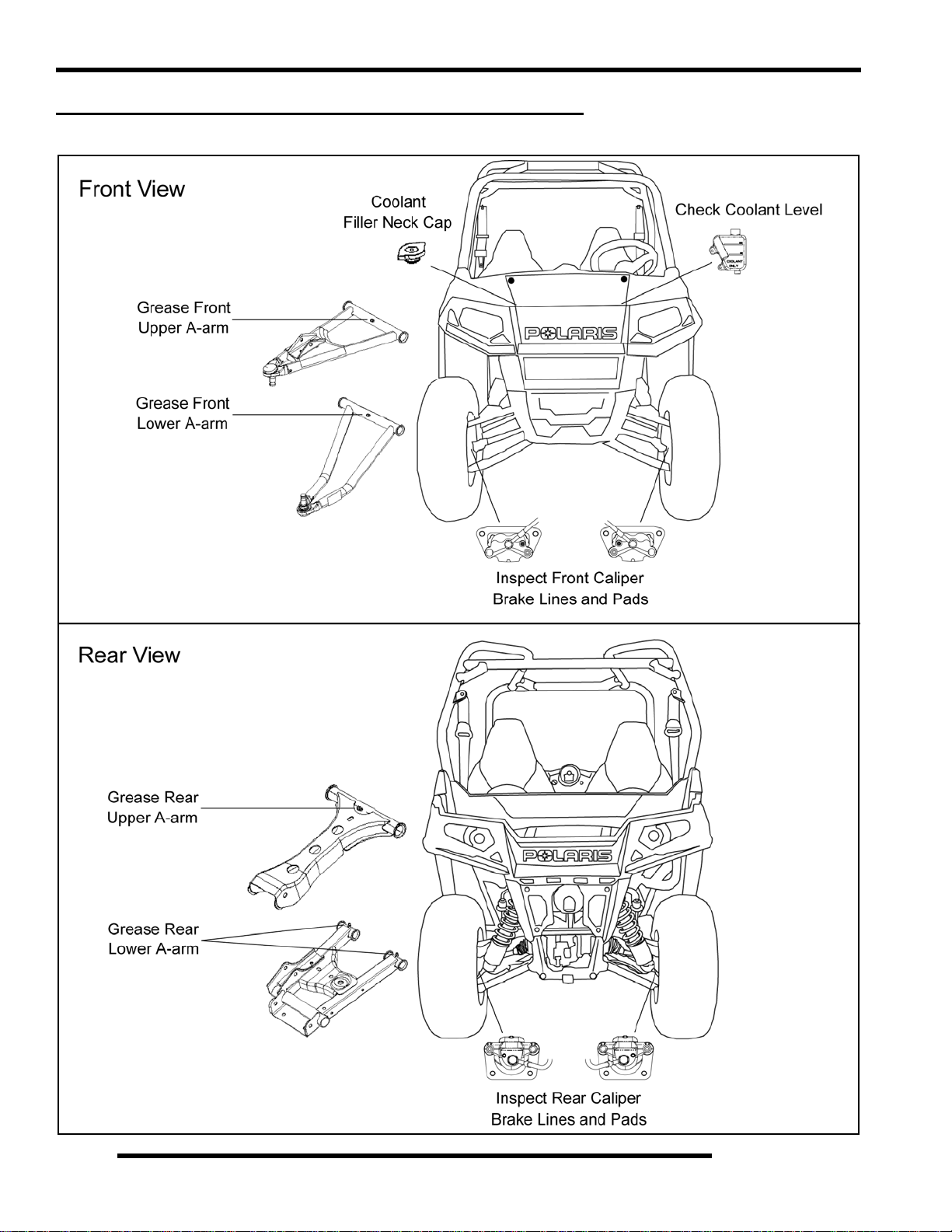
COMPONENT INSPECTION / SERVICE LOCATIONS
Front and Rear View
Standard RZR Shown
Standard RZR Shown
2.6
Page 19
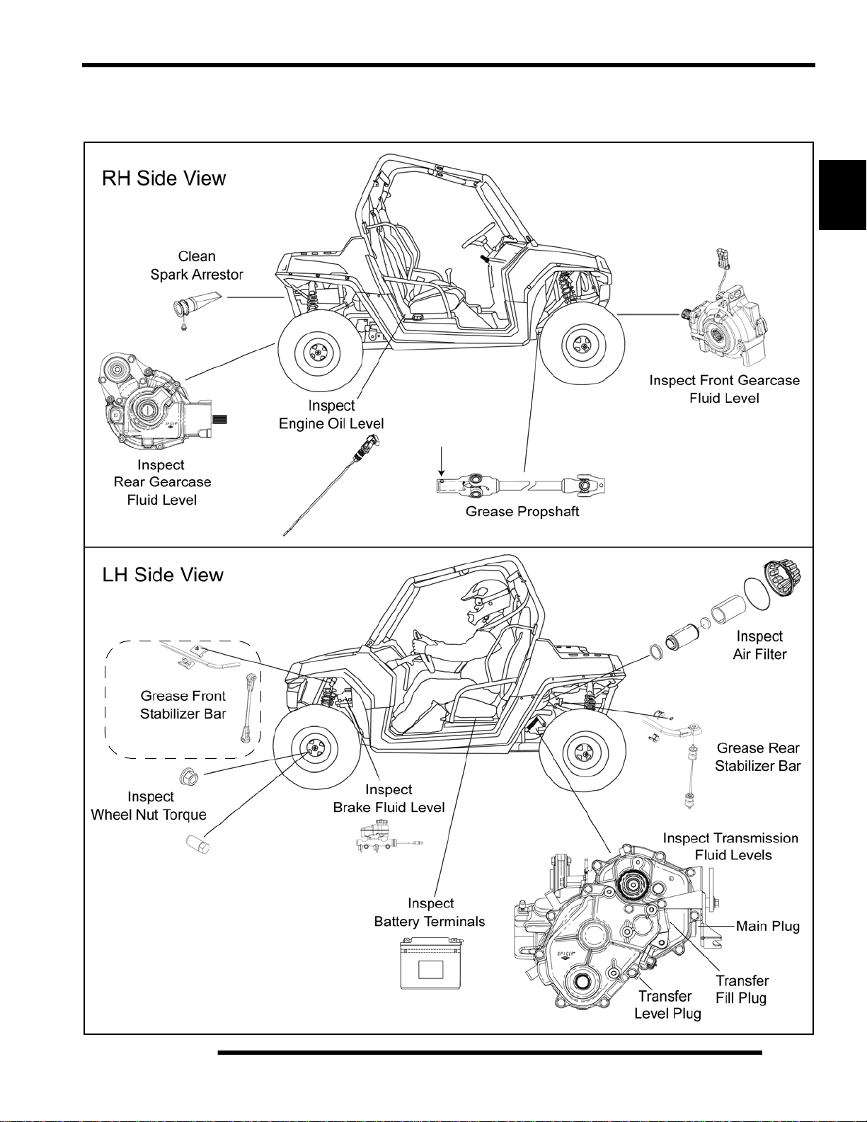
RH and LH Side Views
MAINTENANCE
Standard RZR Shown
Standard RZR Shown
2
*Standard RZR Only
2.7
Page 20
MAINTENANCE
LUBRICANTS / SERVICE PRODUCTS
Polaris Lubricants, Maintenance and Service Products
Part No. Description
Engine Lubricant
2870791 Fogging Oil (12 oz. Aerosol)
2876244
2876245
2873602
2873603
2873604
2871653
2872276
2871654
2870465 Oil Pump for 1 Gallon Jug
2871312 Grease Gun Kit
2871322
PS-4 PLUS Performance Synthetic 2W-50
4-Cycle Engine Oil (Quart)
PS-4 PLUS Performance Synthetic 2W-50
4-Cycle Engine Oil (Gallon)
Gearcase / Transmission Lubricants
AGL - Synthetic ATV Gearcase Lubricant
(1 Qt.) (12 Count)
AGL - Synthetic ATV Gearcase Lubricant
(1 Gal.) (4 Count)
AGL - Synthetic ATV Gearcase Lubricant
(2.5 Gal.) (2 Count)
ATV Angle Drive Fluid
(8 oz.) (12 Count)
ATV Angle Drive Fluid
(2.5 Gal) (2 Count)
Premium Demand Drive Fluid LT
(1 Qt.) (12 Count)
Grease / Specialized Lubricants
Premium All Season Grease
(3 oz. cartridge) (24 Count)
NOTE: Each item can be purchased separately at
your local Polaris dealer.
Part No. Description
Additives / Sealants / Thread Locking Agent s / Misc.
2870585 Loctite™ Primer N, Aerosol, 25 g
2871956
2871949
2871950
2871951
2871952
2871953
2871954
2870584
2870587
2871326
2870652 Fuel Stabilizer (16 oz.) (12 Count)
2872189 DOT 4 Brake Fluid (12 Count)
2871557 Crankcase Sealant, 3-Bond 1215 (5oz.)
2872893 Engine Degreaser (12oz.) (12 Count)
Loctite™ Thread Sealant 565
(50 ml.) (6 Count)
Loctite™ Threadlock 242
(50 ml.) (10 Count)
Loctite™ Threadlock 242
(6 ml.) (12 Count)
Loctite™ Threadlock 262
(50 ml.) (10 Count)
Loctite™ Threadlock 262
(6 ml.) (12 Count)
Loctite™ Threadlock 271
(6 ml.) (12 Count)
Loctite™ Threadlock 271
(36 ml.) (6 Count)
Loctite™ 680-Retaining Compound
(10 ml.)
Loctite™ 518 Gasket Eliminator / Flange
Sealant (50 ml.) (10 Count)
Premium Carbon Clean
(12 oz.) (12 Count)
2871423
2871460 Starter Drive Grease (12 Count)
2871515 Premium U-Joint Lube (3 oz.) (24 Count)
2871551 Premium U-Joint Lube (14 oz.) (10 Count)
2871329 Dielectric Grease (Nyogel™)
2871323 60/40 Coolant (Gallon) (6 Count)
2871534 60/40 Coolant (Quart) (12 Count)
Premium All Season Grease
(14 oz. cartridge) (10 Count)
Coolant
2.8
NOTE: The number count indicated by each part
number in the table above indicates the number of
units that are shipped with each order.
Page 21

MAINTENANCE
MAINTENANCE REFERENCES
Item Ref. Rec. Lube / Fluid Method Frequency*
Change after 25 hrs, and then
Polaris PS-4 PLUS
Engine Oil Page 2.7
Engine Coolant Page 2.6
Brake Fluid Page 2.7 DOT 4 (PN 287218 9)
Transmission
(Main Gearcase)
Transmission
(Transfer Case)
Front Gearcase Page 2.7
Rear Gearcase Page 2.7
Prop Shaft Page 2.7
Control Arm Pivot
Bushings, FT / RR
Stabilizer Bar
Bushings, FT / RR
Page 2.7
Page 2.7
Page 2.6
Page 2.7
Performance Synthetic
2W-50 4-Cycle Engine Oil
Polaris Antifreeze 60/40
(PN 2871534)
AGL Synthetic Gearcase
Lubricant (PN 2873602)
AGL Synthetic Gearcase
Lubricant (PN 2873602)
Premium Demand Drive
Fluid LT (PN 2876251)
ATV Angle Drive Fluid
(PN 2871653)
Polaris Premium U-Joint
Lube (PN 2871551)
Polaris Premium All Season
Grease (PN 2871423)
Polaris Premium All Season
Grease (PN 2871423)
Add oil to proper level on
dipstick.
Fill recovery bottle between
MAX and MIN lines.
Fill reservoir between MAX
and MIN lines.
Add lube to bottom of fill
plug threads. 24 oz. (710 ml)
Add lube to bottom of level
check plug threads.
14 oz. (414 ml)
Add fluid to bottom of fill
plug threads.
6.75 oz. (200 ml)
Add lube to bottom of fill
plug threads. 26 oz. (769 ml)
Locate fitting and grease with
grease gun.
Locate grease fittings on the
upper and lower A-arms of
the front and rear suspension
and grease with grease gun.
(4) Front A-arms
(6) Rear A-arms
Locate grease fittings on the
front and rear stabilizer bars
and grease with grease gun.
(2) Front Stabilizer Bar
(2) Rear Stabilizer Bar
6 months or 100 hours
thereafter; Change more
often in extremely dirty
conditions, or short trip cold
weather operation.
Fill as required. Change
coolant every 2 years.
Fill as required. Change
brake fluid every 2 years.
Change annually***
Change annually***
Change annually***
Change annually***
Semi-annually**
Semi-annually**
Semi-annually**
2
* More often under severe use, such as operated in water or under severe loads.
**Semi-annually or 50 hours of operation (refer to Maintenance Schedule for additional information)
***Annually or 100 hours of operation (refer to Maintenance Schedule for additional information)
2.9
Page 22
MAINTENANCE
GENERAL VEHICLE INSPECTION AND MAINTENANCE
Pre-Ride / Daily Inspection
Perform the following pre-ride inspection daily, and when
servicing the vehicle at each scheduled maintenance.
• Tires - check condition and pressures
• Fuel tank - fill to proper level
• All brakes - check operation and adjustment
• Throttle - check for free operation and closing
• Headlights/Taillights/Brakelights - also check operation
of all indicator lights and switches
• Ignition switch - check for proper function
• Wheels - check for tightness of wheel nuts and axle
nuts; check to be sure axle nuts are secured by cotter
pins
• Air cleaner element - check for dirt; clean or replace
• Steering - check for free operation noting any unusual
looseness in any area
• Loose parts - visually inspect vehicle for any damaged
or loose nuts, bolts or fasteners
• Engine coolant - check for proper level at the recovery
bottle
• Check all front and rear suspension components for
wear or damage.
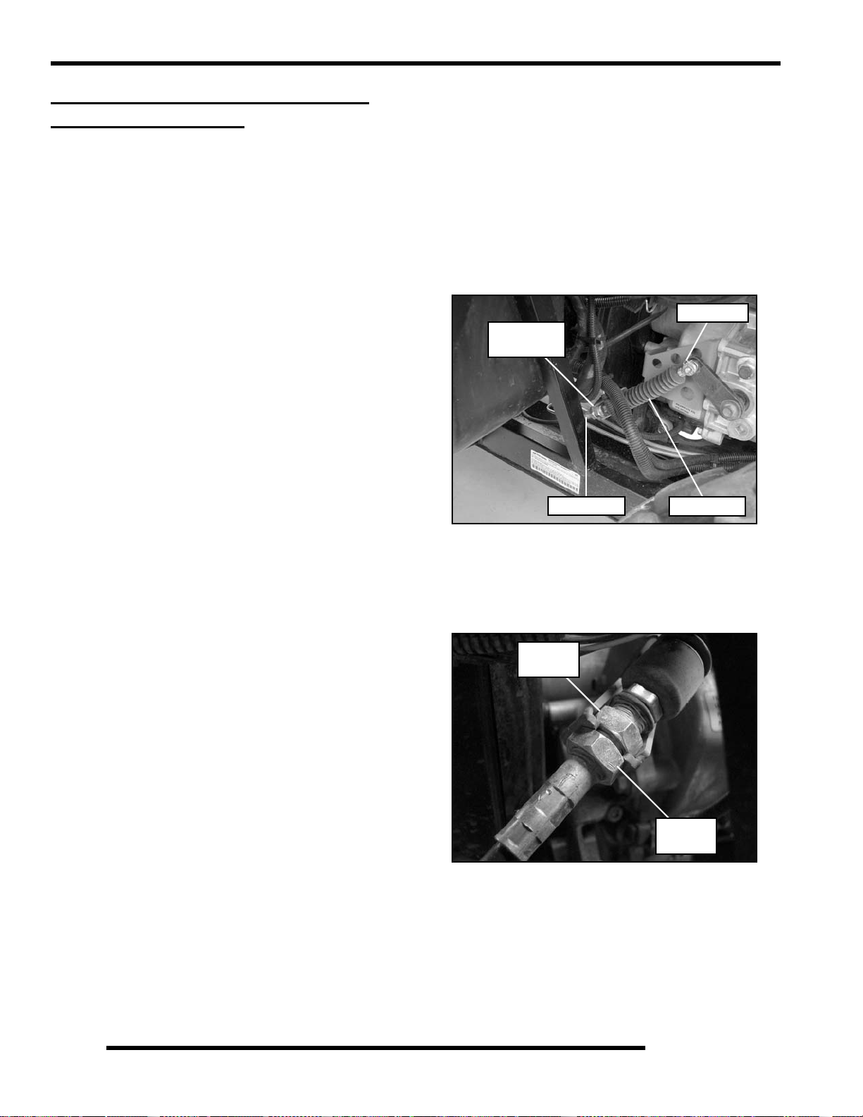
Shift Cable Inspection / Adjustment
Shift cable adjustment may be necessary if symptoms include:
• No AWD or gear position display on instrument cluster
• Ratcheting noise on deceleration
• Inability to engage into a gear
• Excessive gear clash (noise)
• Gear selector moving out of desired range
1. Locate the shift cable in the rear LH wheel well area.
Clevis Pin
Shift Cable
Mount
Shift Cable
2. Inspect shift cable, clevis pin, pivot bushings, and dust
boot. Replace if worn or damaged.
3. If adjustment is required, loosen the lower jam nut and pull
the cable out of the mount to move the upper jam nut.
Upper
Jam Nut
Dust Boot
Frame, Nuts, Bolts, and Fasteners
Periodically inspect the torque of all fasteners in accordance
with the maintenance schedule. Check that all cotter pins are in
place. Refer to specific fastener torques listed in each chapter.
2.10
Lower
Jam Nut
4. Adjust the shift cable so there is the same amount of cable
travel when shifting slightly past the detents of HIGH (H)
gear and PARK (P).
5. Thread the upper or lower jam nut as required to obtain
proper cable adjustment.
NOTE: This procedure may require a few attempts to
obtain the proper adjustment.
Page 23
MAINTENANCE
6. Once the proper adjustment is obtained, place the shift
cable and upper jam nut into the mount. Tighten the lower
jam nut against the mount.
7. Start engine and shift through all gears to ensure the shift
cable is properly adjusted. If transmission still ratchets
after cable adjustment, the transmission will require
service.
FUEL SYSTEM AND AIR INTAKE
Fuel System
WARNING
Gasoline is extremely flammable and explosive
under certain conditions.
Always stop the engine and refuel outdoors or in
a well ventilated area.
Do not smoke or allow open flames or sparks in
or near the area where refueling is performed or
where gasoline is stored.
Do not overfill the tank. Do not fill the tank neck.
If you get gasoline in your eyes or if you swallow
gasoline, seek medical attention immediately.
If you spill gasoline on your skin or clothing,
immediately wash it off with soap and water
and change clothing.
Never start the engine or let it run in an enclosed
area. Engine exhaust fumes are poisonous and
can result loss of consciousness or death
in a short time.
Never drain the fuel when the engine is hot.
Severe burns may result.
2. Be sure fuel line is routed properly.
IMPORTANT: Make sure line is not kinked or pinched.
3. Replace fuel line every two years.
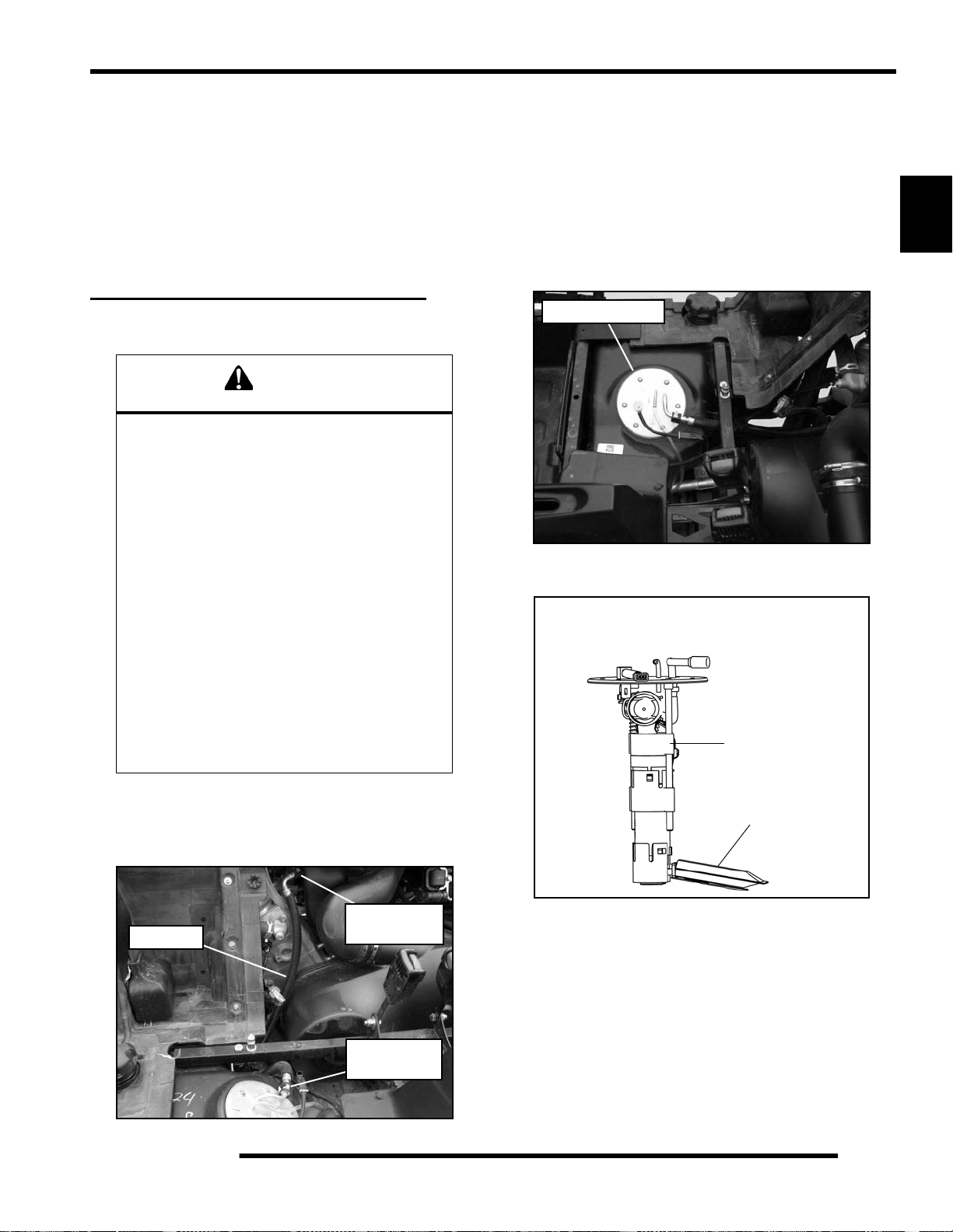
Fuel Pump / Fuel Filters
The 800 EFI RZR engine uses a non-serviceable, high-volume,
high-pressure, fuel pump that includes a preliminary filter and
an internal fine filter located before the pump regulator.
Fuel Pump Asm
NOTE: Neither filter is servicable.
Fuel Pump Asm
Located in Fuel Tank
Fine Filter
2
Fuel Line
1. Check the quick-connect fuel line for signs of wear,
deterioration, damage or leakage. Replace if necessary.
Injector Rail
Fuel Line
Connector
Fuel Pump
Connector
Preliminary Filter
NOTE: For all other information related to the EFI
System, refer to Chapter 4.
Vent Lines
1. Check fuel tank, front gear case, rear gear case and
transmission vent lines for signs of wear, deterioration,
damage or leakage. Replace every two years.
2. Be sure vent lines are routed properly and secured with
cable ties.
IMPORTANT: Ensure lines are not kinked or pinched.
2.11
Page 24
MAINTENANCE
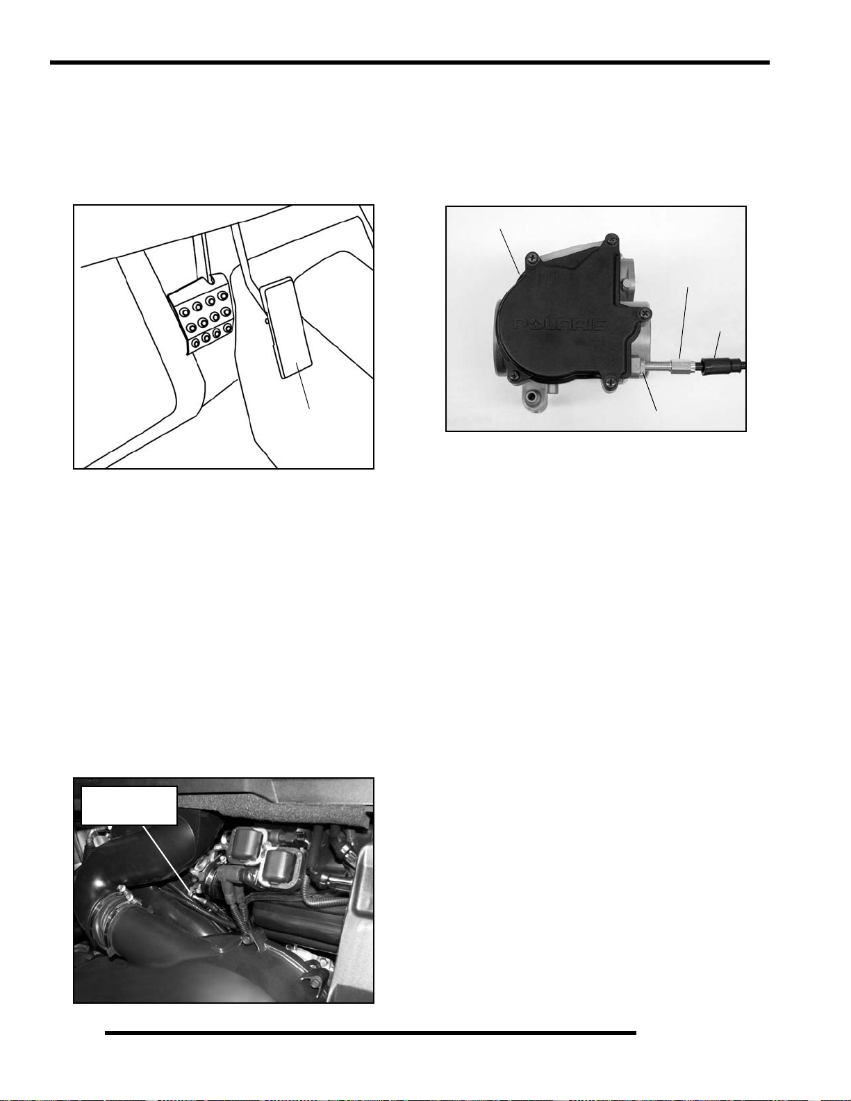
Throttle Pedal Inspection
If the throttle pedal has excessive play due to cable stretch or
cable misadjustment, it will cause a delay in throttle speed.
Also, the throttle may not open fully. If the throttle pedal has no
play, the throttle may be hard to control, and the idle speed may
be erratic.
Throttle Pedal
Check the throttle pedal play periodically in accordance with the
Periodic Maintenance Chart and adjust the play if necessary.
Throttle Freeplay Adjustment
3. Slide back the cable adjuster boot.
4. Using a 10 mm open-end wrench, loosen the adjustment
jam nut.
5. Using an 8 mm open-end wrench, move the cable adjuster
until 1/16” to 1/8” (1.5 - 3 mm) of freeplay is achieved at
the throttle pedal.
Throttle Body
Adjuster
Boot
Jam Nut
NOTE: While adjusting, lightly move the throttle
pedal in and out.
6. Re-tighten the jam nut.
7. Apply a small amount of grease to the inside of the boot and
slide it over the cable adjuster to its original position.
Inspection
1. Place the transmission in the P (Park) position.
2. Start the engine, and warm it up thoroughly.
3. Measure the distance the throttle pedal moves before the
engine begins to pick up speed. Freeplay should be 1/16”
- 1/8” (1.5 - 3 mm).
Adjustment
1. Remove both seats and rear service panel.
2. Locate the throttle cable adjuster at the throttle body.
Throttle Cable
Adjuster
Throttle Cable Replacement
1. Place the vehicle in PARK and stop the engine.
2. Remove the seats and rear service panel (see Chapter 5).
3. Remove the shift handle knob and center console (see
Chapter 5).
4. Remove the rear cargo box and rear bumper as an assembly
(see Chapter 5).
5. Remove the air intake box (see “Air Filter Service”).
6. Remove both PVT outlet and inlet ducts to allow access the
throttle body cover (see Chapter 6).
7. Remove the throttle body cover.
NOTE: Upon removing the cable from the throttle
plate arm, the brass retainer will become loose or
separated from the cable. Take care not to drop
brass retainer upon removal.
8. Pull back on the throttle plate arm and remove the throttle
cable.
9. Using an 8 mm open-end wrench, remove the throttle cable
from the throttle body.
2.12
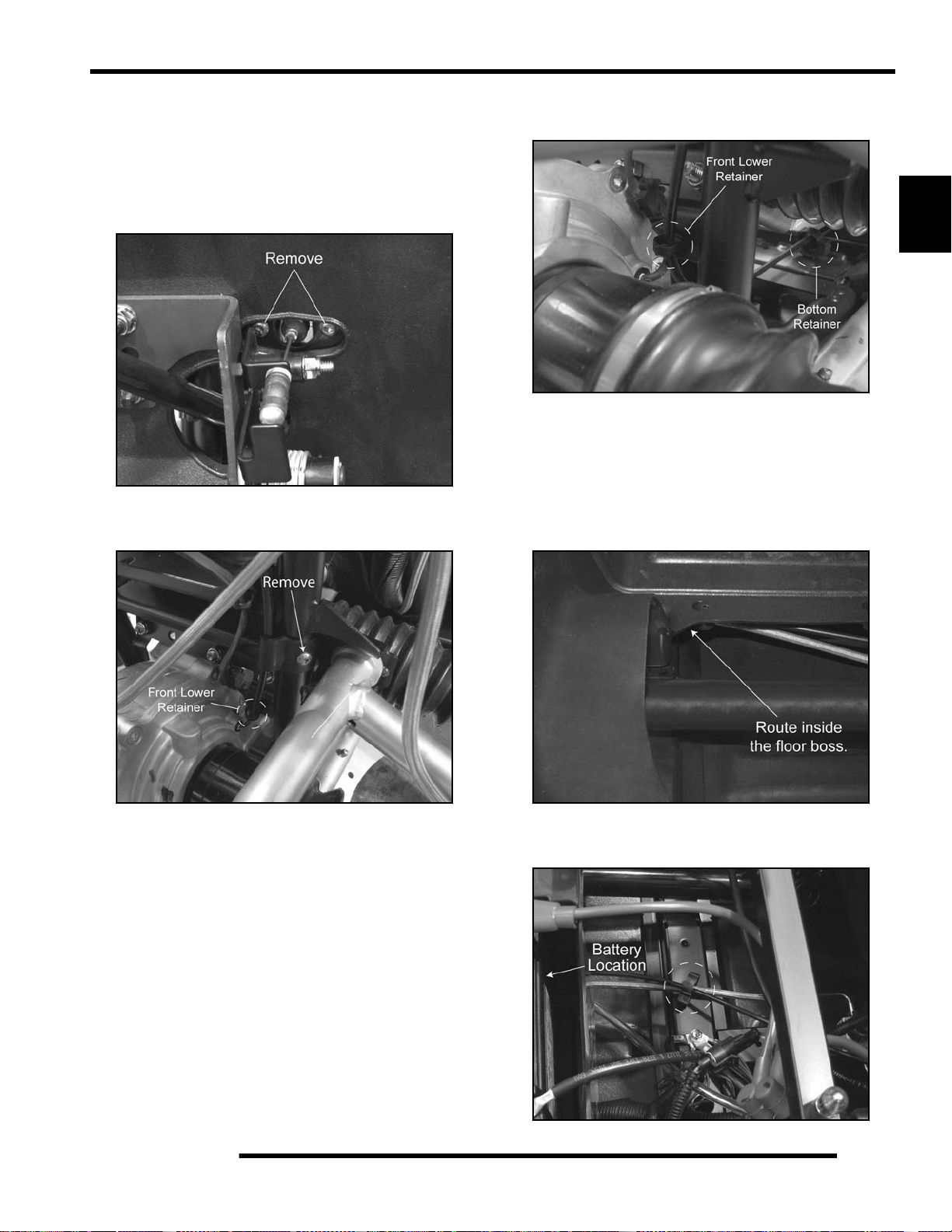
10. Remove the rear floor and rocker panel fasteners to loosen
the floor.
Page 25
MAINTENANCE
11. Lift up on the floor and remove the panduit strap retaining
the throttle cable and brake line to the frame.
12. Remove the cable end and retainer from the throttle foot
pedal.
13. Remove the (2) screws retaining the thro ttle cable b racket
to the frame support.
14. Remove the front upper cable clamp from the vertical frame
tube.
20. Route the cable through the retainer at the botto m of the
frame in the floor console opening.
2
21. Continue to route the cable towards the rear of the vehicle
following the brake line routing.
22. Use the (2) cable ties to retain the throttle cable to the brake
line.
NOTE: Be sure to route the throttle cable inside the
boss on the rear portion of the floor.
15. Push the rear tabs together and remove the front lower cable
retainer.
16. Pull the throttle cable out through the front left wheel well
and discard the cable.
17. Install the new cable into the vehicle through the front left
wheel well. Route the cable over the upper A-arm and
between the front left-hand drive shaft and frame, and
between the front gearcase and frame.
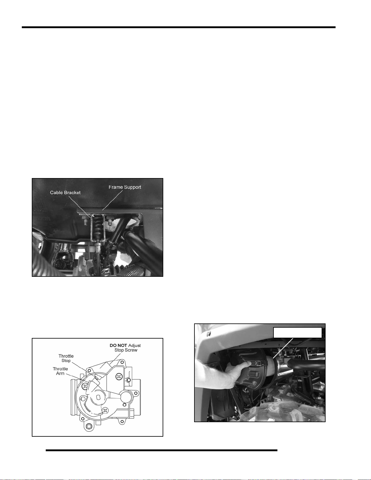
18. Install the front upper cabl e clamp making sure to allow
enough cable slack to attach the cable bracket to the frame
support.
19. Open the front lower cable retainer, place over the cable and
reinstall retainer into the frame hole.
23. Insert the rosebud retainer as shown and route the throttle
cable and brake line through the retainer.
2.13
Page 26
MAINTENANCE
24. Route the cable around the circumference of the PVT cover
up and over to the throttle body.
25. Apply pipe sealant or PTFE Teflon® tape to the threads at
the end of the throttle cable.
NOTE: If using a liquid sealant, do not allow sealant
to contact the internal throttle cable.
26. Screw the throttle cable end into the throttle body.
27. Pull back on the throttle plate arm and in sert the throttle
cable and brass bushing. Pull slack out of the cable at the
foot pedal end to ensure it stays in place.
28. Move to the front of the vehicle and route the upper portion
of the cable inside of the brake line.
29. From the left side of the vehicle, hold and align the throttle
cable bracket to the frame support with your left hand.
Reach into the footwell area with your right hand and start
the screws. NOTE: May require an assistant.
33. Install the throttle body cover and PVT inlet duct.
34. Verify the vehicle is still in PARK.
35. Start the engine and allow it to warm up.
36. Measure the distance the throttle pedal moves before the
engine begins to pick up speed. Freeplay should be 1/16" 1/8" (1.5 - 3 mm).
• If freeplay is correct, proceed to next step.
• If adjustment is required , refer to “Throttle Freeplay
Adjustment” procedure.
37. Using a 10 mm open-end wrench, tighten the jam nut
against the throttle body housing. Torque jam nut to
45 in. lbs. (5 Nm).
38. Apply a small amount of grease to the inside of the boot and
slide it over the cable adjuster.
39. Reassemble the vehicle using the appropriate areas of the
Service Manual as a reference if needed.
40. After reassembly, field test unit to ensure pro per throttle
operation.
Air Filter Service
30. Torque the retaining screws to 50 in. lbs. (5.6 Nm).
31. Install the cable end and retainer into the throttle foot pedal.
32. Move back to the throttle body and check to see that the
throttle plate arm is resting against the stop. If not, turn in
the cable adjuster in (clockwise) until the throttle plate arm
rests on the stop.
It is recommended that the air filter be inspected as part of
pre-ride inspection. When riding in extremely dusty conditions,
apply grease to the seal under the air box cap. In extremely dusty
conditions, air filter replacement will be required more often.
The filter should be inspected using the following procedure.
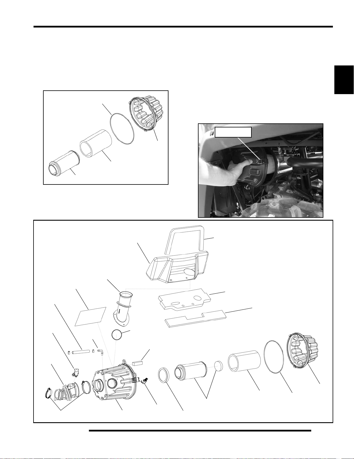
Removal
1. The air box is located just above the rear LH wheel in the
wheel well area.
2. Unlatch the (3) clips and remove the air box cap. Inspect
the seal. It should adhere tightly to the cover and seal all
the way around.
Air Box Location
2.14
3. Remove air filter assembly and remove the pre-filter sleeve.
Page 27
MAINTENANCE
4. Inspect the main air filter element and replace if necessary.
Do not clean the main filter, the filter should be replaced.
NOTE: If the filter has been soaked with fuel or oil it
must be replaced.
5. Wash pre-filter in warm soapy water and allow it to air dry.
NOTE: If unable to clean the pre-filter, replace it.
Seal
Cap
Pre-Filter
Sleeve
Air Filter
NOTE: Service more frequently if vehicle is operated
in wet conditions or at high throttle openings for
extended periods.
Installation
1. Clean the air box thoroughly.
2. Install a new or clean pre-filter over the main air filter
element.
3. Place filter ring over the end of the filter and install the filter
into the air box. Be sure the filter fits tightly in the air box.
NOTE: Apply a small amount of general purpose
grease to the sealing edges of the filter and the air
box cap seal before installing.
4. Install air box cap and secure with clips.
Secure Clips
2
Breather
Hose
T-MAP
Sensor
Boot
Clamps
Foil
Fitting
Air Intake Duct
Air Box Can
Intake Box
Seal
Breather
Filter
Clip (3)
Filter Ring
Air Filter
Front
Foam Seal
Primary
Foam Seal
Intake Seal
Pre-Filter
Sleeve
Cap
Seal
2.15
Page 28
MAINTENANCE
ENGINE
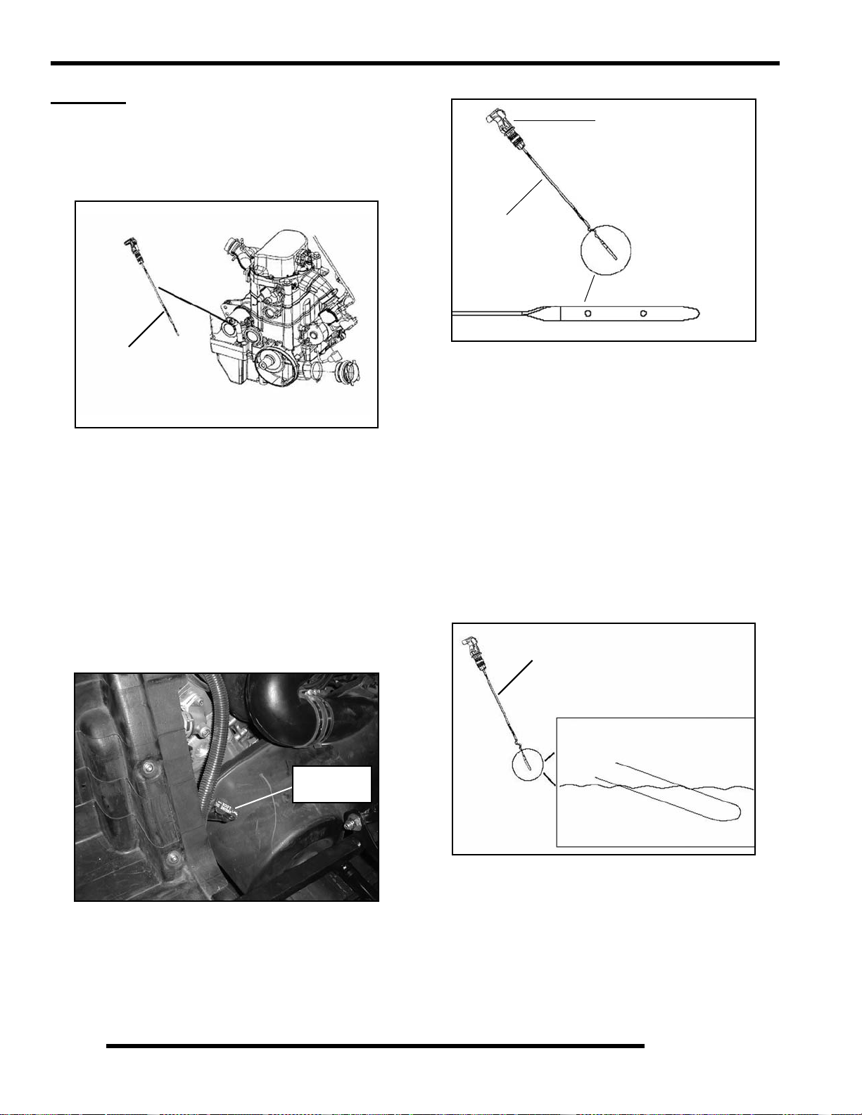
Engine Oil Level
The twin cylinder engine is a wet-sump engine, meaning the oil
is contained in the bottom of the crankcase. To check the oil
level follow the procedure listed below.
Dipstick
1. Position vehicle on a level surface.
2. Place the transmission in PARK (P).
3. Be sure the machine has sat for awhile before removing the
dipstick.
IMPORTANT: Do not run the machine and then check
the dipstick.
4. Remove both seats and the rear service panel.
Lever Lock
Dipstick
SAFE
6. Reinstall the dipstick completely, but do not lock it.
NOTE: Make certain the dipstick is inserted all the
way into the filler tube to keep the a ngle and de pth of
dipstick consistent.
7. Remove the dipstick and check the oil level. Maintain the
oil level in the “SAFE” range. Add oil as indicated by the
level on the dipstick. Do not overfill (see NOTE below).
NOTE: Due to the dipstick entry angle into the
crankcase, the oil level will read higher on the
bottom side of the dipstick. Proper level indication
is determined on the upper surface of th e d ip stick a s
it is being removed, regardless of the level marks
being on top or on bottom (see the next illustration).
ADD 8 OZ
5. Stop engine and lift the lever lock. Remove dipstick and
wipe dry with a clean cloth.
Dipstick
Lever Lock
2.16
Dipstick
Always read top side of dipstick to
properly check oil level in crankcase
NOTE: A rising oil level between checks in cool
weather driving can indicate contaminants such as
gas or moisture collecting in the crankcase. If the oil
level is over the full mark, change the oil
immediately.
8. Reinstall the dipstick and seat the lever lock.
Page 29
MAINTENANCE
Engine Oil and Filter Service
Always change engine oil and filter at the intervals outlined in
the Periodic Maintenance Chart. Always change the oil filter
whenever changing the engine oil.
WARNING
Personal injury can occur when handling used
oil. Hot oil can cause burns or skin damage.
Recommended Engine Oil:
PS-4 PLUS 2W-50 Synthetic 4-Cycle
Engine Oil (PN 2876244) (Quart)
Ambient Temperature Range
-40° F to 120° F
1. Position vehicle on a level surface.
2. Place the transmission in PARK (P).
3. Start the engine. Allow it to idle for two to three minutes
until warm. Stop the engine.
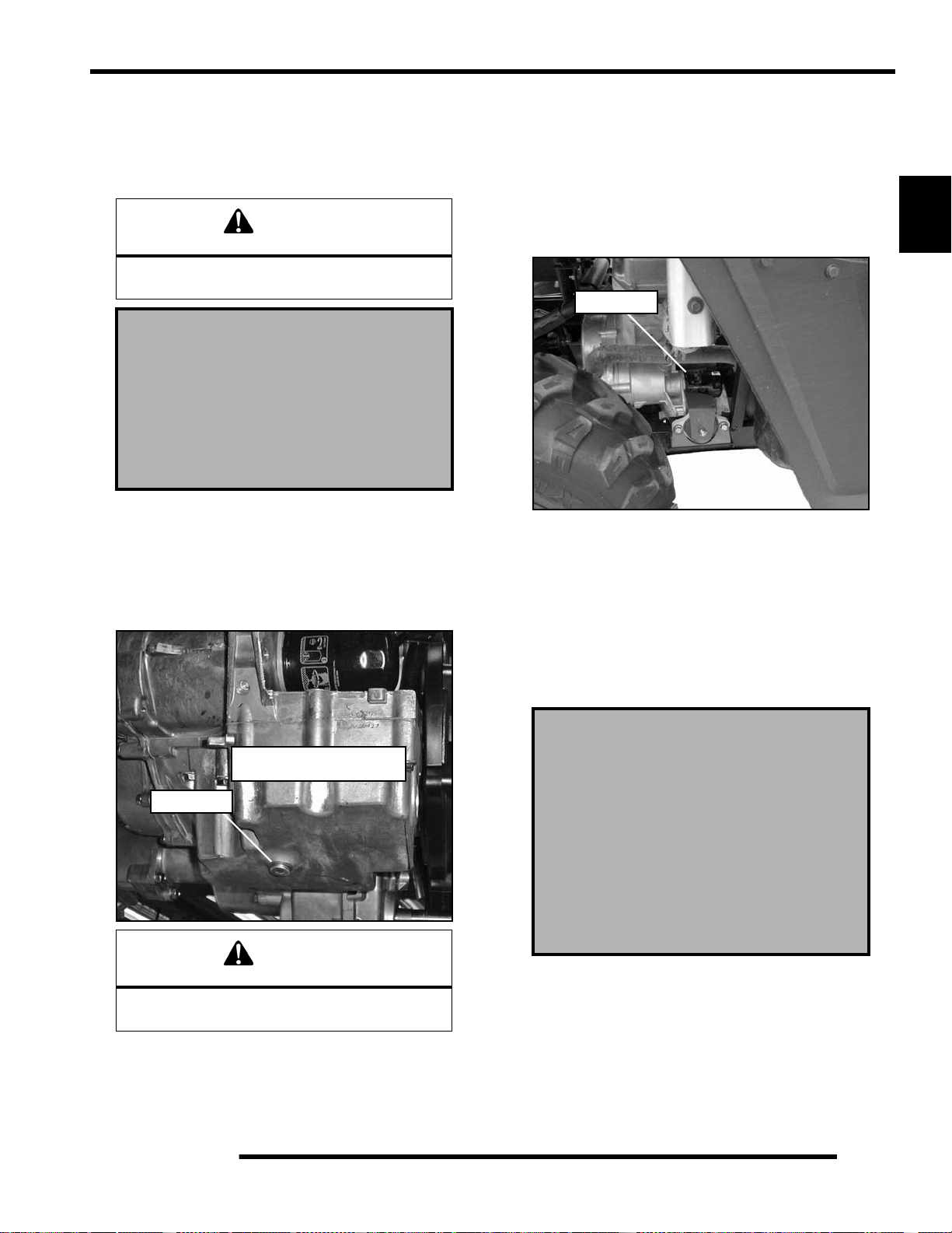
4. Clean area around oil drain plug at bottom of engine.
NOTE: The sealing surface on the drain plug should
be clean and free of burrs, nicks or scratches.
8. Reinstall drain plug and torque to 16 ft. lbs. (22 Nm).
9. Remove both seats and rear service panel.
10. Place shop towels beneath oil filter. Using Oil Filter
Wrench (PV-43527) and a 3/8” extension, turn the oil filter
counter-clockwise to remove it.
Oil Filter
11. Using a clean dry cloth, clean filter sealing surface on the
crankcase.
12. Lubricate O-ring on new filter with a film of fresh engine
oil. Check to make sure the O-ring is in good condition.
13. Install new filter and turn by hand until filter gasket contacts
the sealing surface, then turn an additional 1/2 turn.
2
NOTE: Drain plug is accessed
through the skid plate.
Drain Plug
CAUTION
Oil may be hot. Do not allow hot oil to come into
contact with skin, as serious burns may result.
5. Place a drain pan beneath engine crankcase and remove the
drain plug.
6. Allow oil to drain completely.
7. Replace the sealing washer on drain plug.
14. Remove dipstick and fill sump with 2 quarts (1.9 l) of
PS-4 PLUS 2W-50 Synthetic Engine Oil (PN 2876244).
Crankcase Drain Plug Torque:
16 ft. lbs. (22 Nm)
Oil Filter Torque:
Turn by hand until filter gasket contacts
sealing surface, then turn an
additional 1/2 turn
Oil Filter Wrench:
(PV-43527)
15. Verify the transmission is still positi oned in PARK (P).
16. Start the engine and let it idle for one to two minutes.
17. Stop the engine and inspect for leaks.
18. Re-check the oil level on the dipstick and add oil as
necessary to bring the level to the upper mark on the
dipstick.
19. Dispose of used oil and oil filter properly.
2.17
Page 30
MAINTENANCE
Engine Breather Hose Inspection
The engine is equipped with a breather hose. Inspect the
breather hose for possible kinks or wear. The hose is form fitted for a proper fit. Follow the breather hose from the side of
the airbox to the engine valve cover.
Breather
Hose
NOTE: Make sure line is not kinked or pinched.
Engine and Transmission Mount Locations
Periodically inspect engine and transmission mounts for cracks
or damage.
Rear Mount
A smooth idle generally indicates good compression. Low
engine compression is rarely a factor in running condition
problems above idle speed.
A cylinder leakdown test is the best indication of engine
condition. Follow manufacturer's instructions to perform a
cylinder leakage test (never use high pressure leakage testers, as
crankshaft seals may dislodge and leak).
Cylinder Compression
800: 150-170 PSI
800 HO: 165-185 PSI
Cylinder Leakdown
Service Limit 15%
(Inspect for cause if test exceeds 15%)
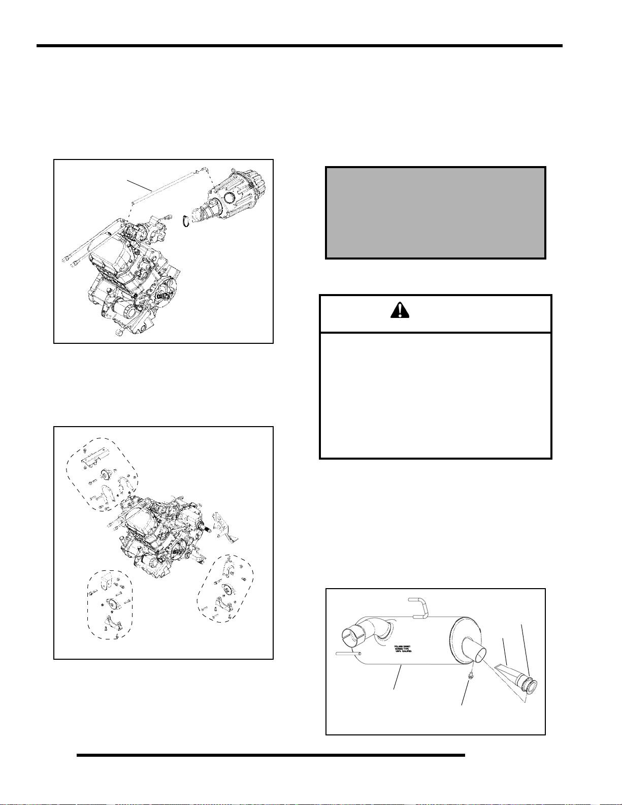
Exhaust - Spark Arrestor
WARNING
Do not clean spark arrestor immediately after the
engine has been run, as the exhaust system
becomes very hot. Serious burns could result from
contact with the exhaust components. Allow
components to cool sufficiently before proceeding.
Wear eye protection and gloves.
Never run the engine in an enclosed area. Exhaust
contains poisonous carbon monoxide gas that can
cause loss of consciousness or death in a very
short time.
LH Mount
RH Mount
Compression and Leakdown Test
NOTE: This engine does NOT have decompression
components. Compression readings will vary in
proportion to cranking speed during the test.
2.18
Periodically clean spark arrestor to remove accumulated carbon.
1. Remove the retaining screw and remove the arrestor from
the end of the silencer.
2. Use a non-synthetic brush to clean the arrestor screen. A
synthetic brush may melt if components are warm.
3. Inspect the screen for wear and damage. Replace if needed.
4. Reinstall the arrestor and torque the screw to 40 in. lbs.
(4.5 Nm).
Arrestor
Screen
Silencer
Retaining
Screw
Page 31

TRANSMISSION AND GEARCASES
Transmission / Gearcase S pecification Chart
MAINTENANCE
G
EARCASE LUBRICANT CAPACITY FILL PLUG TORQUE
Transmission
(Main Gearcase)
Transmission
(Transfer Case)
Front Gearcase
Rear Gearcase ATV Angle Drive Fluid 26 oz. (769 ml) 40-50 ft. lbs. (54-68 Nm) 30-45 in. lbs. (3-5 Nm)
Transmission Lubrication
NOTE: It is important to follow the transmission and
gearcase maintenance intervals described in the
Periodic Maintenance Chart. Regular fluid level
inspections on these components should be
performed as well.
Transmission Specifications
AGL - Synthetic ATV
Gearcase Lubricant
AGL - Synthetic ATV
Gearcase Lubricant
Premium Demand Drive
Fluid LT
24 oz. (710 ml) 40-50 ft. lbs. (54-68 Nm) 30-45 in. lbs. (3-5 Nm)
14 oz. (414 ml) 40-50 ft. lbs. (54-68 Nm) 30-45 in. lbs. (3-5 Nm)
6.75 oz. (200 ml) 8- 1 0 ft. lbs. (11-14 Nm) 8-10 ft. lbs. (11-14 Nm)
Transfer Case - Lubricant Level Check:
1. Position vehicle on a level surface.
2. Remove the fill plug.
3. Remove the level check plug.
4. Add the recommended fluid through the fill plug hole until
it begins to flow out the level check plug hole.
DRAIN / LEVEL CHECK
P
LUG TORQUE
Specified Lubricant:
AGL Synthetic Gearcase Lubricant
Fill Plug
(PN 2873602)
2
Approximate Capacity at Change:
Main Gearcase - 24 oz. (710 ml)
Transfer Case - 14 oz. (414 ml)
Drain / Level Plug Torque:
30-45 in. lbs. (3-5 Nm)
Fill Plug Torque:
40-50 ft. lbs. (54-68 Nm)
The transmission lubricant levels should be checked and
changed in accordance with the maintenance schedule.
• Be sure vehicle is positioned on a level surface when
checking or changing fluid.
• Check vent hose to be sure it is routed properly and
unobstructed.
Level Check Plug
Drain Plug
5. Reinstall the level check plug and torque to 30-45 in. lbs.
(3-5 Nm).
6. Reinstall the fill plug and torque to 40-50 ft. lbs.
(54-68 Nm).
2.19
Page 32

MAINTENANCE
Main Gearcase - Lubricant Level Check:
The fill plug is located on the side of the gearcase just below the
shift lever bell crank. Maintain the fluid level even with the
bottom of the fill plug hole.
1. Position vehicle on a level surface.
2. Remove the fill plug.
3. Check the fluid level.
Transfer Case
Drain Plug
Main Gearcase
Drain Plug
Transfer Case Lubricant Change:
Fill Plug /
Level Check Plug
4. If fluid level is not at fill plug hole, add the recom m e nded
fluid as needed.
5. Reinstall the fill plug and torque to 40-50 ft. lbs.
(54-68 Nm).
Trans mission Lubricant Change:
The lubricant change procedure is relatively the same for the
main gearcase and the transfer case. To minimize confusion,
perform the lubricant change on only one gearcase at a time.
Access the drain plugs through the drain holes in the skid plate.
1. Remove the fill plug and the level check plug (refer to
“Transfer Case - Lubricant Level Check”).
2. Place a drain pan under the transfer case drain plug.
3. Remove the drain plug and allow to drain completely.
4. Clean the drain plug.
5. Reinstall the drain plug with a new o-ring and torque to
30-45 in. lbs. (3-5 Nm).
6. Add the recommended fluid through the fill plug hole until
it begins to flow out the check plug hole. Do not overfill.
7. Reinstall the level check plug and torque to 30-45 in. lbs.
(3-5 Nm).
8. Reinstall the fill plug and torque to 40-50 ft. lbs.
(54-68 Nm).
Main Gearcase Lubricant Change:
9. Remove the fill plug (refer to “Main Gearcase - Lubricant
Level Check”).
10. Place a drain pan under the main gearcase drain plug.
11. Remove the drain plug and allow to drain completely.
12. Clean the drain plug.
13. Reinstall the drain pl ug with a new o-ring and torque to
30-45 in. lbs. (3-5 Nm).
14. Add the recommended fluid through the fill plug hole.
Maintain the fluid level at the bottom of the fill plug ho le
when filling the Main Gearcase. Do not overfill.
15. Reinstall the fill plug and torque to 40-50 ft. lbs.
(54-68 Nm).
16. Check for leaks. Discard the used lubricant properly.
2.20
Page 33

MAINTENANCE
Front Gearcase Lubrication
The front gearcase lubricant level should be checked and
changed in accordance with the maintenance schedule.
• Be sure vehicle is positioned on a level surface when
checking or changing fluid.
• Check vent hose to be sure it is routed properly and
unobstructed.
Front Gearcase Specifications
Specified Lubricant:
Premium Demand Drive Fluid LT
(PN 2876251)
Capacity: 6.75 oz. (200 ml)
Fill Plug: 8-10 ft. lbs. (11-14 Nm)
Drain Plug: 8-10 ft. lbs. (11-14 Nm)
1. Position vehicle on a level surface.
2. Remove the fill plug and check the fluid level.
3. Add the recommended fluid as needed.
4. Reinstall the fill plug and torque to 8-10 ft. lbs. (11-14 Nm).
Lubricant Change:
The drain plug is located on the bottom of the gearcase.
Fill Plug
8-10 ft. lbs.
(11-14 Nm)
2
Lubricant Level Check:
The fill plug is located on the bottom right side of the front
gearcase. Maintain the lubricant level even with the bottom
threads of the fill plug hole.
Drain Plug
8-10 ft. lbs.
(11-14 Nm)
1. Remove the fill plug.
2. Place a drain pan under the drain plug.
3. Remove the drain plug and allow fluid t o drain completely.
4. Clean the drain plug. Inspect the O-ring and replace if
damaged.
5. Reinstall the drain plug; torque to 8-10 ft. lbs. (11-14 Nm).
6. Add the recommended fluid. Maintain the lubricant level
even with the bottom threads of the fill plug hole.
7. Reinstall the fill plug; torque to 8-10 ft. lbs. (11-14 Nm).
8. Check for leaks. Discard the used lubricant properly.
Fill Plug
8-10 ft. lbs.
(11-14 Nm)
2.21
Page 34

MAINTENANCE
Rear Gearcase Lubrication
Rear Gearcase Specifications
Specified Lubricant:
ATV Angle Drive Fluid (PN 2871653)
Capacity: 26 oz. (769 ml)
Fill Plug Torque: 40-50 ft. lbs. (54-68 Nm)
Drain Plug Torque: 30-45 in. lbs. (3-5 Nm)
Lubricant Level Check:
The fill plug is located on the right side of the rear gearcase.
Maintain the fluid level even with the bottom of th e threads of
the fill plug hole.
Fill Plug
40-50 ft. lbs.
(54-68 Nm)
Lubricant Change:
The drain plug is located on the bottom right side of the rear
gearcase.
Fill Plug
Drain Plug
1. Remove the fill plug.
2. Place a drain pan under the drain plug.
Maintain Level at
Bottom of Threads
1. Position the vehicle on a level surface.
2. Remove the fill plug and check the fluid level. The
lubricant level should be even with the bottom of the
threads of the fill plug hole.
3. Add the recommended lubricant as needed.
4. Reinstall the fill plug and torque to 40-50 ft. lbs.
(54-68 Nm)
3. Remove the drain plug and allow the lubricant to drain
completely.
4. Clean the drain plug.
5. Reinstall the drain plug with new O-ring and torque to
30-45 in. lbs. (3-5 Nm).
Fill Plug
40-50 ft. lbs.
(54-68 Nm)
Maintain Level at
Bottom of Threads
6. Add the recommended lubricant. Maintain the fluid level
even with the bottom threads of the fill plug hole.
Drain Plug
30-45 in. lbs.
(3-5 Nm)
2.22
7. Reinstall the fill plug and torque to 40-50 ft. lbs.
(54-68 Nm).
8. Check for leaks. Discard used lubricant properly.
Page 35

MAINTENANCE
COOLING SYSTEM
Cooling System Overview
The engine coolant level is controlled, or maintained, by the
recovery system. The recovery system components are the
recovery bottle, radiator filler neck, radiator pressure cap and
connecting hose.
As coolant operating temperature increases, the expanding
(heated) excess coolant is forced out of the radiator past the
pressure cap and into the recovery bottle. As engine coolant
temperature decreases the contracting (cooled) coolant is drawn
back up from the tank past the pressure cap and into the radiator.
NOTE: Some coolant level drop on new machines is
normal as the system is purging itself of trapped air.
Observe coolant levels often during the break-in
period.
NOTE: Overheating of engine could occur if air is
not fully purged from system.
Polaris Premium 60/40 is already premixed and ready to use. Do
not dilute with water.
Coolant Level Inspection
The pressure cap and recovery bottle are located under the front
hood of the vehicle. The coolant level must be maintained
between the minimum and maximum levels indicated on the
recovery bottle.
4. If the coolant level is below the MIN line, inspect the
coolant level in the radiator.
NOTE: If overheating is evident, allow system to
cool completely and check coolant level in the
radiator and inspect for signs of trapped air in
system.
2
WARNING
Never remove the pressure cap when the
engine is warm or hot. Escaping steam can
cause severe burns. The engine must be cool
before removing the pressure cap.
5. Remove the pressure cap. Using a funnel, add coolant to
the top of the filler neck.
6. Reinstall the pressure cap.
NOTE: Use of a non-standard pressure cap will not
allow the recovery system to function properly.
7. Remove recovery bottle cap and add coolant using a funnel.
8. Fill recovery bottle to MAX level with Polaris 60/40
premix Anti Freeze/Coolant or 50/50 or 60/40 mixture of
antifreeze and distilled water as required for freeze
protection in your area.
9. Reinstall the recovery bottle cap.
10. If coolant was required, start engine and check for leaks.
Make sure radiator fins are clean to prevent overheating.
Recovery Bottle
Pressure Cap
With the engine at operating temperature, the coolant level
should be between the upper and lower marks on the coolant
recovery bottle. If not, perform the following procedure.
1. Position the vehicle on a level surface.
2. Remove the hood by lifting it straight up from the front cab
to allow the inserts to disengage from the grommets.
3. View the coolant level in the recovery bottle.
Coolant Strength / Type
Tes t the strength of the coolant using an antifreeze hydrometer.
Antifreeze Hydrometer
• A 50/50 or 60/40 mixture of antifreeze and distilled
water will provide the optimum cooling, corrosion
protection, and antifreeze protection.
• Do not use tap water, straight antifreeze, or straight
water in the system. Tap water contains minerals and
impurities which build up in the system.
• Straight water or antifreeze may cause the system to
freeze, corrode, or overheat.
Polaris 60/40 Anti-Freeze / Coolant
(PN 2871323)
2.23
Page 36

MAINTENANCE
Cooling System Pressure Test
Refer to Chapter 3 for cooling system pressure test procedure.
Cooling System Hoses
1. Inspect all hoses for cracks, deterioration, abrasion or
leaks. Replace if necessary.
Filler Neck
Recovery
Bottle
T-Fitting
2. Check tightness of all hose clamps.
CAUTION
Do not over-tighten hose clamps at radiator, or
radiator fitting may distort, causing a restriction
to coolant flow. Radiator hose clamp torque is
36 in. lbs. (4 Nm).
2. Carefully straighten any bent radiator fins.
3. Remove any obstructions with compressed air or low
pressure water.
CAUTION
Washing the vehicle with a high-pressure
washer could damage the radiator fins and
impair the radiators effectiveness. Use of a
high-pressure washer is not recommended.
Coolant Drain / Radiator Removal
Coolant Drain
1. Remove the front hood.
WARNING
Never drain the coolant when the engine and
radiator are warm or hot. Hot coolant can cause
severe burns. Allow engine and radiator to cool.
2. Slowly remove the pressure cap to relieve any cooling
system pressure.
3. Place a suitable drain pan underneath the radiator fitting on
the front RH side of the vehicle.
4. Drain the coolant from the radiator by removing the lower
coolant hose from the radiator as shown. Properly dispose
of the coolant.
Radiator
1. Check radiator (A) air passages for restrictions or damage.
A
Flush radiator fins
in this direction
2.24
Drain Here
5. Allow coolant to completely drain.
Page 37

MAINTENANCE
Radiator Removal
1. Remove the front bumper (see Chapter 5).
2. Remove the upper engine outlet hose and recovery hose
from the top of the radiator.
3. Remove the (2) upper radiator retaining bolts and the (4)
bolts retaining the lower radiator mount bracket. Remove
the bracket from the frame.
4. Disconnect the fan motor and remove the radiator from the
vehicle. Take care not to damage the cooling fins.
5. Reverse procedure for installation.
Fan Motor Asm.
Recovery
Hose
Inserts
FINAL DRIVE / WHEEL AND TIRE
Wheel, Hub, and Spindle Torque Table
Item Nut Type Specification
Aluminum Wheels
(Cast)
Steel Wheels
(Black / Camo)
Hub Retaining Nuts
(Front & Rear)
Aluminum Wheel
90 ft. lbs. (122 Nm)
NOTE: Do not lubricate the stud or the lug nut.
Wheel Removal
1. Position the vehicle on a level surface.
2. Place the transmission in PARK (P) and stop the engine.
Lug Nut
#1
Flange Nut
#2
- 80 ft. lbs. (108 Nm)
#1
90 ft. lbs. (122 Nm)
27 ft. lbs. (37 Nm)
Steel Wheel
27 ft. lbs. (37 Nm)
#2
2
T-Fitting
Engine
Inlet Hose
Engine
Outlet Hose
Grommets
Radiator
Screws
3. Loosen the wheel nuts slightly. If wheel hub removal is
required, remove the cotter pin and loosen the hub nut
slightly.
4. Elevate the appropriate side of the vehicle by placing a
suitable stand under the frame.
5. Remove the wheel nuts and remove the wheel.
6. If hub removal is required, remove the hub nut and washers.
Wheel Installation
1. Verify the transmission is still in PARK (P).
2. Install the wheel hub, washers, and hub nut, if previously
removed.
3. Place the wheel in the correct position on the wheel hub.
Be sure the valve stem is toward the outside and rotation
arrows on the tire point toward forward rotation.
4. Attach the wheel nuts and finger tighten them.
2.25
Page 38

MAINTENANCE
5. Carefully lower the vehicle to the ground.
6. Torque the wheel nuts and/or hub nut to the proper torque
specification listed in the torque table at the beginning of
this section.
7. If hub nut was removed, install a new cotter pin after the
hub nut has been tightened.
WARNING
Operating a RANGER with worn tires will
increase the possibility of the vehicle skidding
easily with possible loss of control.
Use a new
Note
Tire Rotation
Wheel Nuts (4)
cotter pin
Hub Nut
Valve stem
facing outward
CAUTION
If wheels are improperly installed it could affect
vehicle handling and tire wear. On vehicles with
tapered rear wheel nuts, make sure tapered end
of nut goes into taper on wheel.
Tire Inspection
• Improper tire inflation may affect vehicle
maneuverability.
• When replacing a tire always use original equipment
size and type.
• The use of non-standard size or type tires may affect
vehicle handling.
Worn tires can cause an accident.
Always replace tires when the tread depth
measures 1/8", (.3 cm) or less.
Tire Pressure
CAUTION
Maintain proper tire pressure.
Refer to the warning tire pressure decal
applied to the vehicle.
Tire Pressure Inspection (Cold)
Front Rear
8 psi (55 kPa) 8 (55 kPa)
Drive Shaft Boot Inspection
Inspect the front and rear drive shaft boots for damage, tears,
wear, or leaking grease. If the rubber boots exhibit any of these
symptoms, replace the boot(s). Refer to Chapter 7 for drive shaft
boot replacement.
Front Boots
Tire Tread Depth
Always replace tires when tread depth is worn to 1/8" (3 mm) or
less.
Tread
Depth 1/8" (3 mm)
2.26
Rear Boots
Page 39

MAINTENANCE
ELECTRICAL AND IGNITION SYSTEM
Battery Maintenance
Keep battery terminals and connections free of corrosion. If
cleaning is necessary, remove the corrosion with a stiff wire
brush. W ash with a solution of one tablespoon baking soda and
one cup water. Rinse well with tap water and dry off with clean
shop towels. Coat the terminals with dielectric grease or
petroleum jelly.
WARNING
Battery electrolyte is poisonous. It contains
sulfuric acid. Serious burns can result from
contact with skin, eyes or clothing. Antidote:
External: Flush with water.
Internal: Drink large quantities of water or milk.
Follow with milk of magnesia, beaten egg, or
vegetable oil. Call physician immediately.
Eyes: Flush with water for 15 minutes and get
prompt medical attention.
Batteries produce explosive gases.
Keep sparks, flame, cigarettes, etc. away.
Ventilate when charging or using in an enclosed
space. Always shield eyes when
working near batteries.
KEEP OUT OF REACH OF CHILDREN.
NOTE: Batteries must be fully charged before use or
battery life will be reduced by 10-30% of full
potential. Charge battery f or 3-5 hours at a current
equivalent to 1/10 of the battery’s rated amp/hour
capacity. Do not use the vehicle’s stator/alternator
to charge a new battery.
Battery Removal
1. Remove the driver’s seat to access the battery.
Battery
2
2. Disconnect the black (negative) battery cable.
3. Disconnect the red (positive) battery cable.
4. Remove the rubber strap and lift the battery out of the
vehicle.
CAUTION
To reduce the chance of sparks: Whenever
removing the battery, disconnect the black
(negative) cable first. When reinstalling the
battery, install the black (negative) cable last.
Battery Installation
IMPORTANT: Using a new battery that has not been
fully charged can damage the battery and result in a
shorter life. It can also hinder vehicle performance.
Follow the battery charging procedure before
installing the battery.
1. Ensure the battery is fully charged.
2. Place the battery in the battery holder and secure with
rubber strap.
3. Coat the terminals with dielectric grease or petroleum jelly.
4. Connect and tighten the red (positive) cable first.
5. Connect and tighten the black (negative) cable last.
6. Verify that cables are properly routed and reinstall the
driver’s seat.
2.27
Page 40

MAINTENANCE
Battery Off Season Storage
Whenever the vehicle is not used for a period of three months or
more, remove the battery from the vehicle, ensure that it's fully
charged, and store it out of the sun in a cool, dry place. Check
battery voltage each month during storage and recharge as
needed to maintain a full charge.
NOTE: Battery charge can be maintained by using a
Polaris battery tender charger or by charging about
once a month to make up for normal self-discharge.
Battery tenders can be left connected during the
storage period, and will automatically charge the
battery if the voltage drops below a pre-determined
point.
Battery Charging (Maintenance Free)
The sealed battery is already filled with electrolyte and has been
sealed at the factory. Never pry the sealing strip of f or add any
type of fluid to this battery.
The single most important thing about maintaining a sealed
battery is to keep it fully charged. Since the battery is sealed and
the sealing strip cannot be removed, you must use a voltmeter or
multimeter to measure the DC voltage at the battery terminals.
Spark Plug Service
1. Remove both driver and passenger seats.
2. Remove the rear service panel.
WARNING
A hot exhaust system and engine can cause serious
burns. Allow engine to cool or wear protective
gloves when removing the spark plugs
3. The PTO side spark plug can be accessed with the service
panel removed. The MAG side spark plug can be accessed
through the rear RH wheel well area.
4. Remove both spark plug caps.
1. Check the battery voltage with a voltmeter or multimeter.
The battery voltage should read 12.8 VDC or higher.
2. If the voltage is less than 12.8 volts, charge the battery at
1.2 amps or less until battery voltage is 12.8 VDC or
greater.
NOTE: When using an automatic charger, refer to
the charger manufacturer’s instructions for battery
charging directions. When using a constant current
charger, follow the guidelines in the following table:
State of
Charge
100% 12.8 - 13.0 VDC
75% - 100% 12.5 - 12.8 VDC
50% - 75% 12.0 - 12.5 VDC Needs Charge 5 - 11 hrs
25% - 50% 11.5 - 12.0 VDC Needs Charge
0% - 25% 11.5 VDC or less Needs Charge 20 hrs
Voltage Action
None, check
again in 3
months
May need slight
charge, check
again in 3
months
Charge
Time
None
Required
3 - 6 hrs
At least 13
hrs, verify
state of
charge
5. Clean plug area so no dirt and debris can fall into engine
when plugs are removed.
6. Remove spark plugs.
7. Inspect electrodes for wear and carbon buildup. Look for
a sharp outer edge with no rounding or erosion of the
electrodes.
Inspect electrode for
wear and buildup
8. Clean with electrical contact cleaner or a glass bead spark
plug cleaner only. CAUTION: A wire brush or coated
abrasive should not be used.
2.28
Page 41

MAINTENANCE
9. Measure gap with a wire gauge. Refer to specifications in
the following illustration for proper spark plug type and
gap. Adjust gap if necessary by carefully bending the side
electrode.
Spark Plug Gap
Gap - .035" (0.90 mm)
10. If necessary, replace spark plug with proper type.
CAUTION: Severe engine damage may occur if the
incorrect spark plug is used.
11. Apply anti-seize compound to the spark plug threads.
12. Install spark plug and torque to specification.
Recommended Spark Plug:
Champion RC7YC3
Spark Plug Torque:
18 ft. lbs. (24 Nm)
STEERING
Steering Inspection
The steering components should be checked periodically for
loose fasteners, worn tie rod ends, ball joints, and damage. Also
check to make sure all cotter pins are in place. If cotter pins are
removed, they must not be re–used. Always use new cotter pins.
Replace any worn or damaged steering components. Steering
should move freely through the entire range of travel without
binding. Check routing of all cables, hoses, and wiring to be
sure the steering mechanism is not restricted or limited.
NOTE: Whenever steering components are
replaced, check front end alignment.
WARNING
Due to the critical nature of the procedures outlined in
this chapter, Polaris recommends steering component
repair and adjustment be performed by an authorized
Polaris MSD certified technician when replacing
worn or damaged steering parts.
Use only genuine Polaris replacement parts.
2
Engine To Frame Ground
Inspect engine ground cable connection. Be sure it is clean and
tight. The ground cable runs from the engine starter motor to the
ground terminal location under the driver’ s seat near the battery.
Ground
Terminal Location
Engine
Ground Strap
Steering Wheel Freeplay
Check the steering wheel for specified freeplay and operation.
1. Position the vehicle on level ground.
2. Lightly turn the steering wheel left and right.
3. There should be 0.8”-1.0” (20-25 mm) of freeplay.
4. If there is excessive freeplay or the steering feels rough,
inspect the following components.
• Tie Rod Ends
• Steering Shaft U-Joints
• Steering Gearbox
U-Joints
Tie Rod
Tie Rod
Gearbox
2.29
Page 42

MAINTENANCE
Steering Inspection / Tie Rod Ends and Hubs
• To check for play in the tie rod end, grasp the steering
tie rod and pull in all directions feeling for movement.
Toe Alignment Inspection
1. Place machine on a smooth level surface.
2. Set steering wheel in a straight ahead position and secure
the steering wheel in this position.
3. Place a chalk mark on the center line of the front tires
approximately 10” (25.4 cm) from the floor or as close to
the hub/axle center line as possible.
Measurement “B”
Chalk Mark
Measurement “A”
• Elevate front end of machine so front wheels are off the
ground. Check for any looseness in front hub and wheel
assembly by grasping the tire firmly at top and bottom
first, and then at front and rear. Try to move the wheel
and hub by pushing inward and pulling outward.
Check for Loose Wheel or Hub
• If abnormal movement is detected, inspect the hub and
wheel assembly to determine the cause (possible loose
wheel nuts or loose front hub components).
• Refer to Chapter 7 “Final Drive” for front hub service
procedures.
NOTE: It is important that the height of both marks
be equally positioned in order to get an accurate
measurement.
4. Measure the distance between the marks and record the
measurement. Call this measurement “A”.
5. Rotate the tires 180
backward. Position chalk marks facing rearward, even with
the hub/axle center line.
6. Again measure the distance between the marks and record.
Call this measurement “B”. Subtract measurement “B”
from measurement “A”. The difference between
measurements “A” and “B” is the vehicle toe alignment.
The recommended vehicle toe tolerance is 1/8” to 1/4”
(.3 to .6 cm) toe out. This means the measurement at the
front of the tire (A) is 1/8” to 1/ 4” (.3 to .6 cm) wider than
the measurement at the rear (B).
° by moving vehicle forward or
= In. / mm.
Wheel Toe-Out:
(A) - (B) = 1/8 - 1/4" (.3 to .6 cm)
2.30
Page 43

MAINTENANCE
Toe Adjustment
If toe alignment is incorrect, measure the distance between
vehicle center and each wheel. This will tell you which tie rod
needs adjusting.
NOTE: Be sure steering wheel is straight ahead
before determining which tie rod(s) need
adjustment.
CAUTION
During tie rod adjustment, it is very important that
the following precautions be taken when
tightening tie rod end jam nuts.
If the rod end is positioned incorrectly it will not
pivot, and may break.
To adjust toe alignment:
• Hold tie rod end to keep it from rotating.
• Loosen jam nuts at both ends of the tie rod.
• Shorten or lengthen the tie rod until alignment is as
required to achieve the proper toe setting as specified in
Toe Alignment Inspection.
SUSPENSION (RZR)
Spring Preload Adjustment
The front and rear shock absorber springs are adjustable by
rotating the adjustment cam to change spring tension preload.
2
WARNING
Uneven adjustment may cause poor handling of the
vehicle, which could result in an accident and
serious injury or death. Always adjust both the left
and right spring preloads equally.
Suspension Spring Adjustment
1. Position the vehicle on a level surface and stop the engine.
2. Raise and safely support the front or rear of the vehicle off
the ground to allow the suspension to fully extend.
NOTE: The tires should not be touching the ground.
3. To adjust the suspension, rotate the adjustment cam
clockwise to increase spring tension or counter-clockwise
to decrease spring tension.
• IMPORTANT: When tightening the tie rod end jam
nuts, the rod ends must be held parallel to prevent rod
end damage and premature wear. Damage may not be
immediately apparent if done incorrectly.
• After alignment is complete, torque jam nuts to
specification.
= T
Tie Rod Jam Nut Torque:
12-14 ft. lbs. (16-19 Nm)
Cam
Decrease
Preload
Increase
Preload
Shock Spanner Wrench
(PN 2870872)
4. Each notch of the adjustment will add 6% - 8% more
preload to the spring over the primary position.
2.31
Page 44

MAINTENANCE
SUSPENSION (RZR “S”)
Spring Preload Adjustment
The front and rear shocks have a preload adjustment.
Suspension spring preload may be adjusted to suit different
riding conditions or vehicle payloads.
WARNING
Uneven adjustment may cause poor handling of the
vehicle, which could result in an accident and
serious injury or death. Always adjust both the left
and right spring preloads equally.
1. Raise and safely support the front or rear of the vehicle off
the ground to allow the suspension to fully extend.
2. Loosen the upper jam nut adjustment ring. Turn the lower
adjustment ring (1) clockwise to increase preload or
counter-clockwise to decrease preload.
Factory Preload Setting
3.5 in. (8.9 cm)
3. Once you have obtained the correct preload, holding the
lower adjustment ring while tightening the upper
adjustment ring to lock them in place.
Shock Compression Adjustment
The compression damping adjustment is located on top of the
shock ‘Piggyback’ reservoir of each shock.
Use a flat blade screwdriver to make damping adjustments.
NOTE: When the adjuster screw is turned clockwise
until it stops, the damping is in the fully closed
position.
Turn the clicker clockwise to increase compression damping.
Turn the clicker counter-clockwise to decrease compression
damping.
NOTE: The factory setting is 8 clicks from closed
(see “Compression Adjustment Table”).
Increase
Damping
Decrease
Damping
Decrease
Preload
Spring
Spacer
Decrease
Preload
Increase
Preload
Ride-In
Spring
1
Front Shock
Factory Preload Setting
5.4 in. (13.7 cm)
Increase
Preload
1
Clicker
Adjuster
Compression Adjustment Table
Setting Compression Damping
Softest 18 clicks from closed
Factory 8 clicks from closed
Firmest 2 clicks from closed
2.32
Rear Shock
Page 45

MAINTENANCE
BRAKE SYSTEM
Brake Fluid Inspection
Always check the brake pedal travel and inspect the brake fluid
reservoir level before each operation. If the fluid level is low,
add DOT 4 brake fluid only.
Brake fluid should be changed every two years. The fluid
should also be changed anytime the fluid becomes
contaminated, the fluid level is below the minimum level, or if
the type and brand of the fluid in the reservoir is unknown.
The brake fluid master cylinder reservoir can be accessed
through the left front wheel well.
1. Position the vehicle on a level surface.
2. Place the transmission in PARK (P).
3. View the brake fluid level in the reservoir. The level should
be between the MAX and MIN level lines.
4. If the fluid level is lower than the MIN level line, add brake
fluid until it reaches the MAX level line.
5. Install the reservoir cap and apply the brake pedal
forcefully for a few seconds and check for fluid leakage
around the master cylinder fittings and the brake caliper
fittings.
Brake Pad / Disc Inspection
1. Check the brake pads for wear, damage, or looseness.
2. Inspect the brake pad wear surface for excessive wear.
3. Pads should be changed when the friction material is worn
to .040” (1 mm).
Measure Pad Material
Thickness
4. Check surface condition of the brake discs.
5. Measure the thickness of the front and rear brake discs.
6. The disc(s) should be replaced if thickness is less than .170”
(4.32 mm).
Measure Brake Disc Thickness
Service Limit:
.040" (1 mm)
2
Maximum
Minimum
Master Cylinder
Rear
Disc
Service Limit:
.170" (4.32 mm)
Front
Disc
Brake Hose and Fitting Inspection
Check brake system hoses and fittings for cracks, deterioration,
abrasion, and leaks. Tighten any loose fittings and replace any
worn or damaged parts.
2.33
Page 46

MAINTENANCE
MAINTENANCE LOG
Service Date Hours / Miles (km) Service Performed / Comments Dealer / Technician
2.34
Page 47

ENGINE
CHAPTER 3
ENGINE
ENGINE SPECIFICATIONS . . . . . . . . . . . . . . . . . . . . . . . . . . . . . . . . . . . . . . . . . . . . . . . 3.2
CRANKCASE EXPLODED VIEWS . . . . . . . . . . . . . . . . . . . . . . . . . . . . . . . . . . . . . . . . .3.2
ENGINE FASTENER TORQUE PATTERNS. . . . . . . . . . . . . . . . . . . . . . . . . . . . . . . . . .3.7
TORQUE SPECIFICATIONS . . . . . . . . . . . . . . . . . . . . . . . . . . . . . . . . . . . . . . . . . . . . . .3.8
800 EFI ENGINE SERVICE SPECIFICATIONS. . . . . . . . . . . . . . . . . . . . . . . . . . . . . . . .3.9
SPECIAL TOOLS . . . . . . . . . . . . . . . . . . . . . . . . . . . . . . . . . . . . . . . . . . . . . . . . . . . . . .3.11
ENGINE COOLING SYSTEM . . . . . . . . . . . . . . . . . . . . . . . . . . . . . . . . . . . . . . . . . . . . . 3.12
COOLING SYSTEM SPECIFICATIONS / PRESSURE TEST . . . . . . . . . . . . . . . . . . . .3.12
COOLING SYSTEM EXPLODED VIEW. . . . . . . . . . . . . . . . . . . . . . . . . . . . . . . . . . . . .3.13
COOLING SYSTEM BLEEDING PROCEDURE . . . . . . . . . . . . . . . . . . . . . . . . . . . . . .3.14
GENERAL ENGINE SERVICE . . . . . . . . . . . . . . . . . . . . . . . . . . . . . . . . . . . . . . . . . . . . 3.15
ENGINE LUBRICATION SPECIFICATIONS . . . . . . . . . . . . . . . . . . . . . . . . . . . . . . . . .3.15
ACCESSIBLE ENGINE COMPONENTS . . . . . . . . . . . . . . . . . . . . . . . . . . . . . . . . . . . .3.15
OIL PRESSURE TEST. . . . . . . . . . . . . . . . . . . . . . . . . . . . . . . . . . . . . . . . . . . . . . . . . .3.15
OIL FLOW CHART. . . . . . . . . . . . . . . . . . . . . . . . . . . . . . . . . . . . . . . . . . . . . . . . . . . . .3.16
ENGINE REMOVAL . . . . . . . . . . . . . . . . . . . . . . . . . . . . . . . . . . . . . . . . . . . . . . . . . . . .3.17
ENGINE / TRANSMISSION SEPARATION . . . . . . . . . . . . . . . . . . . . . . . . . . . . . . . . . .3.23
ENGINE DISASSEMBLY AND INSPECTION. . . . . . . . . . . . . . . . . . . . . . . . . . . . . . . . . 3.24
CYLINDER HEAD ASSEMBLY EXPLODED VIEW . . . . . . . . . . . . . . . . . . . . . . . . . . . .3.24
ROCKER ARMS / PUSH RODS. . . . . . . . . . . . . . . . . . . . . . . . . . . . . . . . . . . . . . . . . . .3.25
CYLINDER HEAD REMOVAL . . . . . . . . . . . . . . . . . . . . . . . . . . . . . . . . . . . . . . . . . . . .3.25
CYLINDER HEAD INSPECTION / WARP. . . . . . . . . . . . . . . . . . . . . . . . . . . . . . . . . . .3.26
VALVE SEAL / SPRING SERVICE (ON ENGINE). . . . . . . . . . . . . . . . . . . . . . . . . . . . .3.26
CYLINDER HEAD DISASSEMBLY . . . . . . . . . . . . . . . . . . . . . . . . . . . . . . . . . . . . . . . .3.27
VALVE INSPECTION. . . . . . . . . . . . . . . . . . . . . . . . . . . . . . . . . . . . . . . . . . . . . . . . . . .3.28
COMBUSTION CHAMBER / VALVE SEAT RECONDITIONING. . . . . . . . . . . . . . . . . .3.29
CYLINDER HEAD REASSEMBLY . . . . . . . . . . . . . . . . . . . . . . . . . . . . . . . . . . . . . . . . .3.31
VALVE SEALING TEST . . . . . . . . . . . . . . . . . . . . . . . . . . . . . . . . . . . . . . . . . . . . . . . . .3.32
CYLINDER REMOVAL. . . . . . . . . . . . . . . . . . . . . . . . . . . . . . . . . . . . . . . . . . . . . . . . . .3.32
VALVE LIFTER REMOVAL / INSPECTION . . . . . . . . . . . . . . . . . . . . . . . . . . . . . . . . . .3.32
PISTON REMOVAL . . . . . . . . . . . . . . . . . . . . . . . . . . . . . . . . . . . . . . . . . . . . . . . . . . . .3.33
CYLINDER INSPECTION. . . . . . . . . . . . . . . . . . . . . . . . . . . . . . . . . . . . . . . . . . . . . . . .3.34
CYLINDER HONE SELECTION AND HONING PROCEDURE. . . . . . . . . . . . . . . . . . .3.35
HONING TO DEGLAZE . . . . . . . . . . . . . . . . . . . . . . . . . . . . . . . . . . . . . . . . . . . . . . . . .3.35
CLEANING THE CYLINDER AFTER HONING . . . . . . . . . . . . . . . . . . . . . . . . . . . . . . .3.35
PISTON-TO-CYLINDER CLEARANCE . . . . . . . . . . . . . . . . . . . . . . . . . . . . . . . . . . . . .3.36
PISTON / ROD INSPECTION. . . . . . . . . . . . . . . . . . . . . . . . . . . . . . . . . . . . . . . . . . . . .3.36
PISTON RING INSTALLED GAP. . . . . . . . . . . . . . . . . . . . . . . . . . . . . . . . . . . . . . . . . .3.37
STARTER DRIVE BENDIX REMOVAL / INSPECTION. . . . . . . . . . . . . . . . . . . . . . . . .3.37
FLYWHEEL / STATOR REMOVAL / INSPECTION. . . . . . . . . . . . . . . . . . . . . . . . . . . .3.38
ENGINE CRANKCASE DISASSEMBLY / INSPECTION. . . . . . . . . . . . . . . . . . . . . . . .3.38
CAMSHAFT INSPECTION. . . . . . . . . . . . . . . . . . . . . . . . . . . . . . . . . . . . . . . . . . . . . . .3.46
ENGINE REASSEMBLY . . . . . . . . . . . . . . . . . . . . . . . . . . . . . . . . . . . . . . . . . . . . . . . . . 3.47
CRANKCASE REASSEMBLY . . . . . . . . . . . . . . . . . . . . . . . . . . . . . . . . . . . . . . . . . . . .3.47
FLYWHEEL / STATOR INSTALLATION . . . . . . . . . . . . . . . . . . . . . . . . . . . . . . . . . . . .3.56
CYLINDER HEAD REASSEMBLY . . . . . . . . . . . . . . . . . . . . . . . . . . . . . . . . . . . . . . . . .3.56
OIL PUMP PRIMING . . . . . . . . . . . . . . . . . . . . . . . . . . . . . . . . . . . . . . . . . . . . . . . . . . .3.58
ENGINE INSTALLATION. . . . . . . . . . . . . . . . . . . . . . . . . . . . . . . . . . . . . . . . . . . . . . . . . 3.59
ENGINE ASSEMBLY AND INSTALLATION. . . . . . . . . . . . . . . . . . . . . . . . . . . . . . . . . .3.59
ENGINE BREAK-IN PERIOD. . . . . . . . . . . . . . . . . . . . . . . . . . . . . . . . . . . . . . . . . . . . .3.60
TROUBLESHOOTING. . . . . . . . . . . . . . . . . . . . . . . . . . . . . . . . . . . . . . . . . . . . . . . . . . . 3.61
ENGINE . . . . . . . . . . . . . . . . . . . . . . . . . . . . . . . . . . . . . . . . . . . . . . . . . . . . . . . . . . . . .3.61
COOLING SYSTEM . . . . . . . . . . . . . . . . . . . . . . . . . . . . . . . . . . . . . . . . . . . . . . . . . . . .3.62
3
3.1
Page 48

ENGINE
ENGINE SPECIFICATIONS
Crankcase Exploded Views
3.2
Page 49

Oil Pump / Water Pump / Engine Cover Exploded View
ENGINE
3
3.3
Page 50

ENGINE
Stator Cover / Starter / Water Pump Oil Filter / Pressure Relief / Exploded View
3.4
Page 51

Cylinder / Cylinder Head / Piston Exploded View
ENGINE
3
3.5
Page 52

ENGINE
Engine EFI Sensors / Valve Cover / General Component Exploded View
3.6
NOTE: See Chapter 4 for more information on the EFI System
Page 53
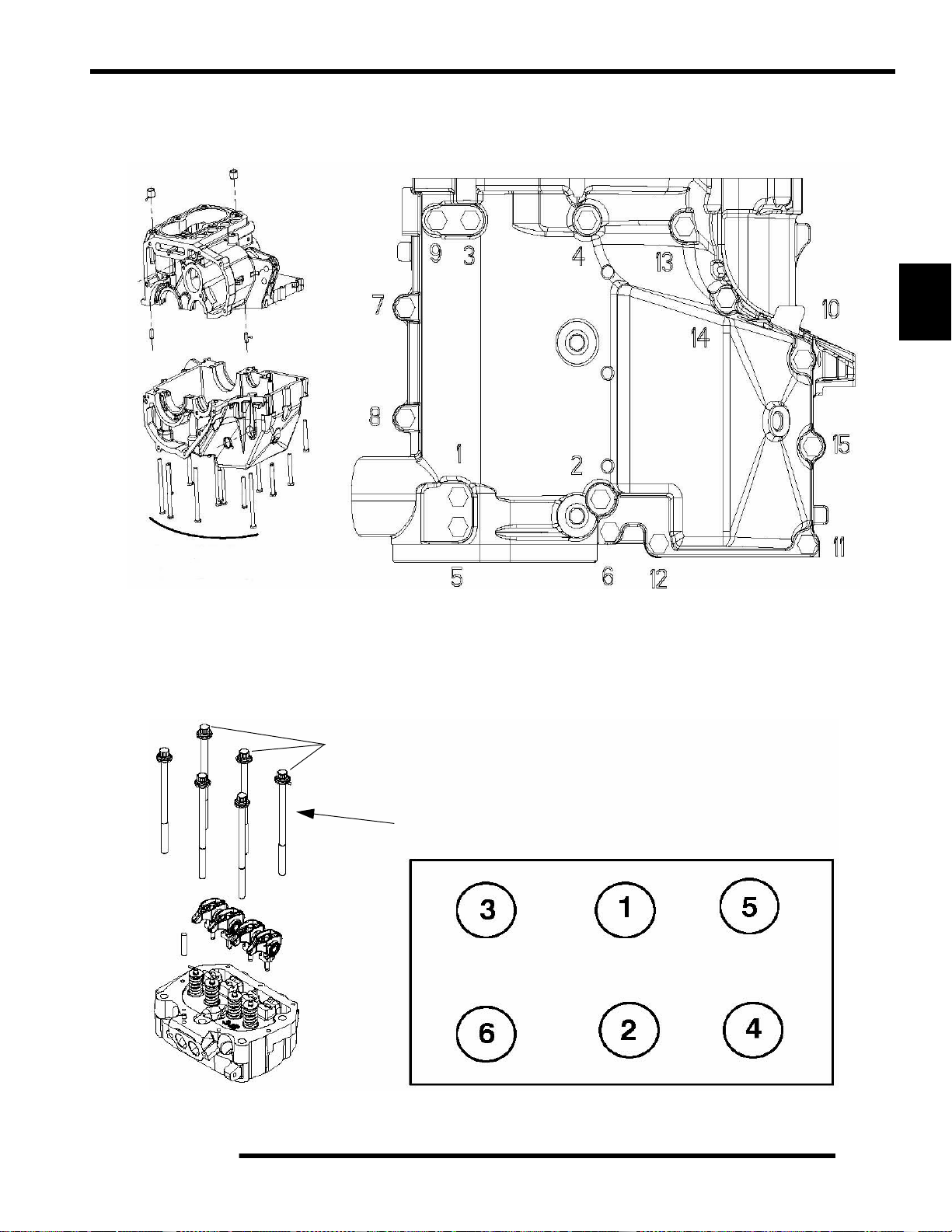
Engine Fastener Torque Patterns
Crankcase Bolt Tighten Sequence
ENGINE
3
22 2 ft. lbs. (30 3 Nm)
Cylinder Head Bolt Tighten Sequence
Lubricate threads and between washer and underside of bolt with engine oil.
Torque in sequence to spec provided, allow the gasket to set for 1 minute, th en
tighten in sequence 90
35 4 ft. lbs.
(47.5 5.5 Nm)
(1/4 turn).
+ 90
(1/4 turn)
3.7
Page 54

ENGINE
Torque Specifications
Engine Torque Specifications
Fastener Size in. lbs. (Nm) ft. lbs. (Nm)
Camshaft Gear 8 mm 22 ± 2 (30 ± 3)
Camshaft Thrust Plate 6 mm 11 5 ± 12 (13 ± 1.35) 9.5 ± 1 (13 ± 1.35)
Throttle Body Adaptor Bolts 8 mm 216 ± 24 (24.5-± 2.7) 18 ± 2 (24.5 ± 2.7)
Counterbalance Gear 8 mm 22 ± 2 (30 ± 3)
Crankcase Bolts 8 mm * 22 ± 2 (30 ± 3)
Crankcase Breather 5 mm 20 ± 5 (2.5 ± 0.55) Cylinder Head Bolts 11 mm * 35 ± 4 (47.5 ± 5.5)
Exhaust Manifold 8 mm 216 ± 24 (24.5 ± 2.70) 18 ± 2 (24.5 ± 2.7)
Flywheel 14 mm 65 ± 7 (88 ± 9.50)
Injector Rail 8 mm 216 ± 24 (24.5 ± 2.70) 1 8 ± 2 (24.5 ± 2.7)
Magneto Cover 6 mm * 96 ± 3 (10.85 ± 0.35) Oil Baffle Weldment 5 mm 60 ± 6 (6.8 ± 0.68) Oil Drain Bolt (Crankcase) 12 mm 192 ± 24 (21.7 ± 2.7) 16 ± (21.7)
Oil Fill Tube Bolt 5 mm 50 ± 5 (5.64 ± 0.56) Oil Filter Pipe Fitting 20 mm 35 ± 4 (47.5 ± 5.4)
Oil Pick Up 5 mm 60 ± 6 (6.8 ± 0.68) Oil Pressure Relief Plug 10 mm 22 ± 2 (30 ± 3) Oil Pump Housing Screw 6 mm * 84 ± 8 (9.50 ± 0.90) Rocker Arm 8 mm * 22 ± 2 (30 ± 3)
Rocker Cover 6 mm * 84 ± 8 (9.5 ± 0.9) Spark Plug 14 mm 216 ± 24 (24.5 ± 2.7) 18 ± 2 (24.5 ± 2.7)
Starter Motor 6 mm * 84 ± 8 (9.5 ± 0.9) Stator Assembly 6 mm 96 ± 3 (10.85 ± 0.35) Stator Housing 6 mm * 96 ± 3 (10.85 ± 0.35) Temperature Switch 3/8 NPT 17 ± 2 (23 ± 3)
Thermostat Housing 6 mm 84 ± 8 (9.5 ± 0.9) Timing Plug 3/4-16 7 - 9 (10 - 12)
Trigger Coil/Stator Wire Holddown 5 mm * 96 ± 3 (10.85 ± 0.35) Water Pump Housing Cover 6 mm * 96 ± 3 (10.85 ± 0.35) Water Pump Impeller Nut 8 mm 108 ± 3 (12 ± 0.35) -
NOTE: * See exploded views for notes or torque sequences.
3.8
Page 55

800 EFI Engine Service Specifications
Cylinder Head - Engine Specifications
Main Component: Cylinder Head EH076OLE022 / EH076OLE072
Cam Lobe Height - Intake 1.333” (33.867 mm) / 1.357” (34.477 mm)
Cam Lobe Height - Exhaust 1.333” (33.867 mm) / 1.342” (34.096 mm)
Camshaft Journal Outer Diameter - Mag 1.654" 0.00039" (42 0.010 mm)
ENGINE
Camshaft Journal Outer Diameter - Center 1.634" 0.00039" (41.50 0.010 mm)
Camshaft
Counter Balance Counter Balance End Play 0.005" (0.127 mm)
Cylinder Head
Valve Seat
Valve Guide
Camshaft Journal Outer Diameter - PTO 1.614" 0.00039" (41 0.010 mm)
Camshaft Journal Bore Inner Diameter - Mag 1.656" 0.00039" (42.07 0.010 mm)
Camshaft Journal Bore Inner Diameter - Center 1.637" 0.00039" (41.58 0.010 mm)
Camshaft Journal Bore Inner Diameter - PTO 1.617" 0.00039" (41.07 0.010 mm)
Camshaft Oil Clearance 0.00276" 0.00079" (0.07 0.02 mm)
Camshaft End Play 0.0167" 0.0098" (0.425 0.25 mm)
Cylinder Head - Surface warp limit 0.00394" (0.1 mm)
Valve Seat - Contacting Width - Intake
Valve Seat - Contacting Width - Exhaust
Valve Seat Angle 45.5 0.255
Valve Guide Inner diameter 0.2367" 0.00029" (6.012 0.007 mm)
Valve Guide Protrusion Above Head 0.807" 0.0039" (20.50 0.01 mm)
0.0472" 0.00787" - 0.0039"
(1.20 0.20 - 0.10mm)
0.0591" 0.00787" - 0.0039"
(1.50 0.20 - 0.10 mm)
3
Valve
Valve Spring
Valve Stem Diameter - Intake 0.2356" 0.00039" (5.985 0.01 mm)
Valve Stem Diameter - Exhaust 0.2351" 0.00039" (5.972 0.01 mm)
Valve Stem Oil Clearance - Intake 0.00228" 0.00098" (0.058 0.025 mm)
Valve Stem Oil Clearance - Exhaust 0.00275"
Valve Stem Overall Length - Intake 4.51" 0.01476" (114.5550 0.375 mm)
Valve Stem Overall Length - Exhaust 4.5453" .01496" (115.45 0.38 mm)
Valve Spring Overall Length - Free Length 1.735" (46.069 mm)
Valve Spring Overall Length - Installed Height
Intake - 1.4638" (37.18 mm)
Exhaust - 1.4736" (37.43 mm)
0.00098" (0.0870 0.025mm)
3.9
Page 56

ENGINE
Cylinder / Piston - Engine Specifications
Main Components: Cylinder / Piston / Connecting Rod EH076OLE022 / EH076OLE072
Cylinder
Lifter
Piston
Piston Pin
Cylinder - Surface warp limit
(mating with cylinder head)
Cylinder Bore - Standard 3.1495" (80 mm)
Cylinder Taper Limit 0.00031" (0.008 mm)
Cylinder Out of Round Limit 0.00030" (0.0075 mm)
Cylinder to Piston Clearance .0015" .00059" (.040 .015mm)
Lifter Outer Diameter Standard 0.84245" 0.00025" (21.39 8 0.00635 mm)
Lifter Block Bore 0.8438" 0.00062" (21.4322 0.0157 mm)
Piston - Standard 3.14803" .00028" (79.960 .007mm)
Piston Standard Inner Diameter of
Piston Pin Bore
Piston Pin Outer Diameter 0.70866" - 0.70846" (18 - 17.995 mm)
Piston Pin - Standard Clearance - Piston Pin to
Pin Bore
Piston Pin - Degree of Fit Piston pin must be push fit (by hand) at 68° F (20° C)
0.004" (0.10 mm)
0.70902" .00012" (18.009 0.003 mm)
0.00047" 0.00024" (0.012 0.006 mm)
Piston / Connecting Rod / Crankshaft - Engine Specifications
Main Components: Piston / Connecting Rod EH076OLE022 / EH076OLE072
T op Ring - Standard 0.0059 0.138" (0.15 0.35mm)
Top Ring - Limit > 15% Leakdown
Installed
Gap
Piston Ring
Ring to
Groove
Clearance
Connecting Rod
Crankshaft Crankshaft Runout Limit 0.00236" (0.060mm)
Second Ring - Standard 0.0098 0.197" (0.25 0.50mm)
Second Ring - Limit > 15% Leakdown
Oil Ring - Standard 0.0196 0.00984" (0.50 0.25mm)
Oil Ring - Limit > 15% Leakdown
T op Ring - Standard 0.0024" 0.0008" (0.060 0.020 mm)
Top Ring - Limit > 15% Leakdown
Second Ring - Standard 0.0028" 0.0008" (0.070 0.020 mm)
Second Ring - Limit > 15% Leakdown
Connecting Rod Small End I.D. 0.7096" 0.70846" (18 17.995 mm)
Connecting Rod Small End
Radial Clearance
Connecting Rod Big End
Side Clearance
Connecting Rod Big End
Radial Clearance
0.0098" 0.00039" (0.025 0.010mm)
0.01181" 0.00591" (0.030 0.015mm)
0.0015" 0.00006" (0.0038 0.0015mm)
3.10
Page 57

Special Tools
ENGINE
Part Number Tool Description
PV-43527 OIL FILTER WRENCH
PU-45257 VALVE SPRING COMPRESSOR
PU-45652 VALVE PRESSURE HOSE
2871043 FLYWHEEL PULLER
2870390 PISTON SUPPORT BLOCK
PU-45497-1 CAM GEAR SPRING INSTALLATION KIT
PU-45497-2 CAM GEAR TOOTH ALIGNMENT TOOL
PU-45498 CAM SPANNER WRENCH
PU-45838 GEAR HOLDER
PA-44995 WA TER PUMP MECHANICAL SEAL INSTALLER
PU-45543 UNIVERSAL DRIVER HANDLE
PA-45483 MAIN SEAL INSTALLER
3
PU-45658 CRANKSHAFT MAIN SEAL SAVER
PA-45401 WATER PUMP SEAL SAVER
2870975 MITY VAC™
PU-45778 OIL SYSTEM PRIMING TOOL
PRESSURE TEST TOOL
3.11
Page 58

ENGINE
ENGINE COOLING SYSTEM
Cooling System Specifications
Condition Specification
Thermostat Open 180° F (82° C)
Thermostat Full Open Lift 6 mm at 203° F (95° C)
Thermostat Closed 171° F (77° C)
System Capacity 4.8 Quarts (4.5 liters)
Pressure Cap Relief 13 PSI
Polaris Premium Antifreeze
2871534 - Quart
2871323 - Gallon
Recommended Coolant
Use only high quality antifreeze/coolant mixed with distilled
water in a 50/50 or 60/40 ratio, depending on freeze protection
required in your area.
3. The system must maintain 10 psi for five minutes or longer.
If pressure loss is evident within five minutes, check the
radiator, hoses, clamps and water pump seals for leakage.
Pressure Cap Test
WARNING
Never remove pressure cap when engine is
warm or hot. The cooling system is under
pressure and serious burns may result.
Allow the engine and cooling system to cool
before servicing.
1. Remove pressure cap and test cap using a commercially
available pressure cap tester.
2. The pressure cap relief pressure is 13 psi. Replace cap if it
does not meet this specification.
Pressure Cap
CAUTION: Using tap water in the cooling system will lead to
a buildup of deposits which may restrict coolant flow and reduce
heat dissipation, resulting in possible engine dam age. Polaris
Premium 60/40 Antifreeze/Coolant is recommended for use in
all cooling systems and comes pre-mixed, ready to use.
Cooling System Pressure Test
1. Remove the front hood.
2. Remove pressure cap and pressure test the cooling system
using a commercially available pressure tester.
Remove
Cap
Test Here
3.12
Page 59

Cooling System Exploded View
Engine Outlet Hose
(Thermostat Housing)
ENGINE
Radiator
Inlet Hose
Engine Inlet Hose
(Water Pump Cover)
Pressure Cap
Filler Neck
Recovery Bottle
To Bottle
Radiator
Outlet Hose
3
Fan Motor
Shroud
To Filler Neck
Coolant Flow Diagram
Engine
Water Pump
Engine
Thermostat Housing
Filler Neck
Recovery Bottle
Radiator
Radiator
3.13
Page 60

ENGINE
Cooling System Bleeding Procedure
WARNING
Always wear safety glasses and proper shop
clothing when performing the procedures in this
manual. Failing to do so may lead to possible
injury or death.
CAUTION
Use caution when performing these procedures.
Coolant may be hot and may cause
severe injury or burns.
NOTE: If the coolant level is LOW in the radiator, or
if there are leaks in the system, the coolant system
will not draw coolant from the reservoir tank.
NOTE: Use this procedure when a unit overheats
and no apparent leaks in the cooling system are
found.
1. Drive the vehicle onto a slight incline and use properly
weight rated ramps. If an incline is not available, slightly
elevate the front of the vehicle.
2. Place the vehicle in Park and block the rear wheels.
3. Remove pressure cap and top off coolant.
4. Remove recovery bottle cap and fill bottle to the full line.
Recovery Bottle
Pressure Cap
5. Leave the cap off of the radiator to allow any possible air
to escape.
6. Start the engine and let it idle for 5-10 minutes or until the
thermostat opens and allows coolant to flow through the
system.
7. Slightly loosen the bleed screw (C) on the thermostat cover
to let air escape. If no air is present, a steady stream of
coolant will stream out. If air is present, the screw will
bubble and sputter as the air escapes.
Pressure Cap
CAUTION
Be sure the engine has cooled and no pressure
is built up in the cooling system before removing
the pressure cap. The coolant may be hot and
could cause severe injury or burns.
Top LH Side
of Engine
C
8. Tighten the bleed screw to 70 ± 10 in.lbs. (8 ± 1.13 Nm) on
the thermostat housing and properly install the pressure
cap.
9. Squeeze the coolant lines by hand to help purge the system
of air.
NOTE: If there is air in the system you will see air
bubbles forming through the radiator filler neck.
3.14
Page 61

ENGINE
10. Add Polaris Premium Antifreeze to the radiator filler neck
if the level goes down. If no bubbles are seen at the filler
neck, the system should be purged of air
WARNING
Be sure to install the pressure cap before
shutting off the engine.
Coolant may spit out of the radiator.
11. Stop the engine and let cool, top off the radiator filler neck
with coolant. If you hear or see a “glug” at the filler neck,
or there is a dropping of the coolant level, indicating that
coolant has been pulled into the system; Fill the recovery
bottle only after you have completely filled the cooling
system at the radiator filler neck.
12. Repeat this procedure, if overheating still occurs.
GENERAL ENGINE SERVICE
Engine Lubrication Specifications
=
Capacity - Approximately 2 U.S. Quarts (1.9 L)
Oil Type - Polaris PS-4 PLUS 2W-50 Synthetic
Filter Wrench - PV-43527 or equivalent
- Oil Pressure Specification -
27-35 psi @ 6000 RPM, Polaris 2W-50
Synthetic, Engine at operating temperature.
Accessible Engine Components
The following components can be serviced or removed with the
engine installed:
• Starter Motor / Drive
• Cylinder Head
• Cylinder
• Piston / Rings
• Rocker Arms
• Water Pump
3
The following components require engine removal for service:
• Flywheel
• Alternator (Stator)
• Counterbalance Shaft or Bearings
• Gear Train Components
• Camshaft
• Oil Pump / Oil Pump Drive Gear
• Connecting Rod
• Crankshaft
• Crankshaft Main Bearings
• Crankcase
Oil Pressure Test
1. Remove blind plug/sender from left side of crankcase.
2. Insert a 1/8 NPT oil pressure gauge adaptor into the
crankcase and attach the gauge.
3. Start engine and allow it to reach operating temperature,
monitoring gauge indicator.
Oil Pressure at Idle: 6 psi
Oil Pressure at 6000 RPM (Engine Hot):
Minimum: 27 psi
Standard: 31 psi
Maximum: 35 psi
3.15
Page 62

ENGINE
Oil Flow Chart
This chart describes the flow of oil through the 800 EFI engine. Beginning in the crankcase sump, the oil is drawn through an oil
galley to the feed side of the oil pump. The oil is then pumped through th e oil filter. If the oil filter is obstructed, a bypass valve
contained in the filter allows oil to bypass the filter element. At this point, the oil is supplied to the main oil galley through a crankcase
passage. Oil is then diverted three ways from the main oil galley, with the first path entering the camshaft bores, onto the rear balance
shaft journal and then draining back into the crankcase sump. The second oil path from the main oil galley feeds the lifter bores and
then drains back to the crankcase sump. The third oil path flows through a crankcase galley to the MAG side crankshaft journal and
also to the front balance shaft journal and onto the crankcase sump. The oil pressure switch is fed off the main oil galley.
3.16
Page 63

ENGINE
Engine Removal
Because of its design configuration, Polaris recommends
removing the engine, transmission, and rear gearcase as one
assembly. Use the following procedure when engine removal is
required.
IMPORTANT: Some engine repair procedures can be
performed without removing the RZR engine
assembly from the vehicle. Refer to “Accessible
Engine Components” on Page 3.15 for further
information.
NOTE: The use of an overhead or portable engine
hoist is the only recommended method for removing
and installing the engine / transmission / rear
gearcase assembly.
NOTE: Have an assistant help guide the engine in
and out of the vehicle while using an engine hoist to
prevent personal injury or damage to vehicle
components.
WARNING
8. Remove the (2) push rivets from the rear of the center
console.
3
9. Remove the (2) fasteners from the rear seat base and
remove the assembly from the vehicle.
Always wear safety glasses and proper shop
clothing when performing the procedures in th is
manual. Failing to do so may lead to possible
injury or death.
1. If vehicle was recently operated, allow it to cool down
before attempting to perform any work.
2. Clean work area.
4. Drain appropriate lubricant(s):
• If servicing the engine, drain engine oil.
• If servicing the transmission, drain the lubricant from
the main gearcase and transfer case.
• If servicing the rear gearcase, drain the gearcase
lubricant.
5. Remove the driver and passenger seats (see Chapter 5).
6. Disconnect (-) negative battery cable.
10. Remove the rear plastic bumper, rear cargo box and box
supports from the vehicle (see Chapter 5).
11. Remove the (2) push rivets and remove the intake box from
the vehicle.
7. Remove the rear service panel (see Chapter 5).
Remove
Push Rivets
3.17
Page 64

ENGINE
12. Elevate the rear of the vehicle off the ground using a
suitable ATV lift and remove both rear wheels.
13. Remove all exhaust components from vehicl e and engin e .
14. Loosen the hose clamp attaching the outlet duct to the PVT
cover. Leave the duct attached to the upper frame support.
Outlet Duct
PVT Cover
15. Remove the (8) screws that retain the PVT cover and
remove cover.
18. Remove the (6) fasteners retaining the upper bolt-in frame
brace and remove it from the vehicle with the ignition coil
and PVT duct attached.
Frame Brace
Ignition
Coil
PVT Duct
19. Remove the upper nut and grommet from the stabilizer bar
linkage on both sides of the vehicle.
16. Remove the high tension leads from the spark pl ugs and
disconnect the ignition coil harness.
Harness
Connection
17. Remove the vent lines from the upper bolt-in frame brace
and plug vent lines to prevent fluid leakage during removal.
20. Remove the (4) fasteners retaining the stabilizer bar and
bracket and remove the assembly from the vehicle.
3.18
21. Remove the engine breather hose from the valve cover.
Page 65
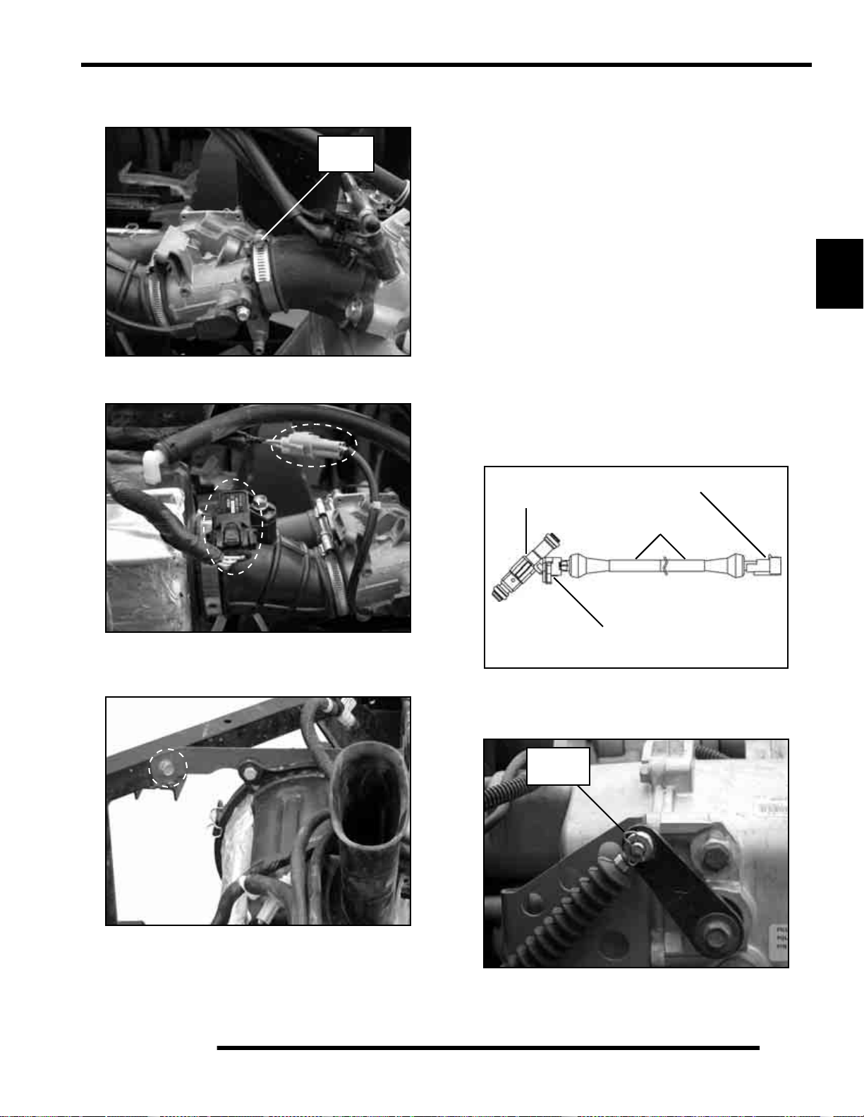
ENGINE
22. Loosen the hose clamp between the throttle body and intake
adaptor.
Loosen
Clamp
23. Disconnect the T-MAP and TPS harnesses (see photo).
25. Remove the airbox and throttle body from the vehicle as an
assembly. Take care in not allowing the throttle cable to
bend excessively or kink. Carefully place the assembly on
the floor next to the vehicle. Insert a shop towel into the
engine intake adaptor to prevent dirt from entering the
engine.
NOTE: Ensure throttle cable is not being
excessively bent or kinked while removed from the
vehicle.
26. Mark the fuel injector harnesses to identify MAG and PTO
harness connections to aid during reassembly. Disconnect
the fuel injector harnesses.
NOTE: The Bosch harness connector and locking
spring is bonded to the fuel injectors with an epoxy
mix. DO NOT attempt to disconnect the Bosch
connector from the fuel injectors. Damage will occur
to the injector and/or harness if attempting to
separate at that location. Separate the fuel injector
from the vehicle by disconnecting at the end of the
harness as shown.
Fuel
Injector
Disconnect Here
3
24. Remove the remaining bolt attaching the airbox to the
frame (see photo).
Harness
DO NOT
Disconnect Here
27. Disconnect the fuel line from the fuel injector rail.
28. Disconnect the shift cable from the transmission bell crank.
Remove
Clip
3.19
Page 66

ENGINE
29. Mark the upper jam nut and loosen the lower jam nut. Pull
the shift cable out of the mount.
Mark Upper
Jam Nut
Lower
Jam Nut
NOTE: If the upper jam nut is moved, shift cable
adjustment will be required during engine
installation (see Chapter 2 “Shift Cable Inspection /
Adjustment”).
30. Disconnect the transmission gear indicator switch harness.
32. Disconnect the stator / alternator harness.
Stator
Connector
33. Disconnect the transmission speed sensor harness.
Speed Sensor
Connector
Gear Switch
Connector
31. Disconnect the CPS harness.
34. Remove the castle nuts from both rear wheel hubs.
CPS
Connector
Castle Nut
3.20
Page 67

ENGINE
35. Remove the through-bolt that attaches the upper A-arm to
the rear hub on both sides of the vehicle.
36. Pivot the A-arms up ward and rear hub carriers downw ard
and remove the drive shafts from the hub carriers.
Hub Carrier
38. Disconnect the engine coolant temperature (ECT) sensor
harness.
ECT
Connector
3
39. Loosen the hose clamp and remove the lower coolant hose
from the water pump cover inlet and drain coolant into a
suitable container.
37. Grasp the rear drive shafts and pull sharply outward on the
shafts to disengage them from the rear gearcase.
NOTE: Clean area around drive shaft orifices on
both sides of rear gearcase and cover orifices using
duct tape. This will prevent the lubricant from
leaking out during removal.
40. Remove the filler neck pressure cap to relieve the cooling
system vacuum.
NOTE: Use a portable wet-vac or syphon to prevent
any coolant from spilling.
41. Remove the upper coolant hose from the thermostat
housing outlet to relieve any coolant vacuum created in the
engine. Allow engine coolant to completely drain.
Properly dispose of the engine coolant / antifreeze.
42. Remove the (+) positive battery cable from the starter
motor terminal and (-) negative battery cable from the
starter motor engine mount.
43. Remove the outer PVT cover.
3.21
Page 68

ENGINE
44. Remove RH engine mount fastener.
45. Remove the (2) lower bolts that retain the LH transmission
mount to the frame.
47. Using an engine hoist, hook a chain between the engine /
transmission mounting plate and the transmission / rear
gearcase mounting plate.
Engine/Transmission
Mount Plate
Transmission/Gearcase
Mount Plate
Remove
(2) Lower Bolts
46. Remove the (2) rear gearcase mount bracket fasteners and
mount bolt and remove bracket from vehicle.
NOTE: The use of an overhead or portable engine
hoist is the only recommended method for removing
and installing the engine / transmission / rear
gearcase assembly.
NOTE: Have an assistant help guide the engine in
and out of the vehicle while using an engine hoist to
prevent personal injury or damage to vehicle
components.
48. Lift the front portion of the assembly out first to allow the
engine valve cover to clear the vehicle frame.
Allow valve cover
to clear frame
3.22
Page 69

ENGINE
49. Remove propshaft from the transmission output shaft.
50. Then move assembly towards the front of the vehicle while
lifting it out to allow the rear gearcase to clear the rear
portion of the frame.
51. Then lift assembly high enough to clear vehicle frame and
completely remove it from the vehicle to a work bench.
Engine / Transmission Separation
3. Remove only the (4) outer fasteners retaining the engine to
the transmission bracket.
3
4. Tilt the assembly up and remove the remaining (2) nuts that
retain the transmission to the engine.
Once the engine / transmission / rear gearcase assembly has
been removed from the vehicle, the engine and transmission will
need to be separated to allow engine servicing. Use the
following procedure to separate the engine from the assembly.
1. Remove the drive belt, drive clutch and driven clutch (see
Chapter 6).
2. Remove the (6) fasteners retaining the inner clutch cover
to the engine and transmission.
5. Carefully separate the engine and perform the required
service (see “Engine Disassembly and Inspection”).
3.23
Page 70

ENGINE
ENGINE DISASSEMBLY AND INSPECTION
Cylinder Head Assembly Exploded View
Rocker Arms
Retainer Locks (keepers)
Spring Retainers
Springs
Push Rods
Valve Spring Seats
Cylinder Head
Valves
Valve Seals
Hydraulic Lifters
3.24
Page 71

ENGINE
Rocker Arms
1. Remove the valve cover.
2. Mark or tag rocker arms in order of disassembly to keep
them in order for reassembly.
3. Inspect the wear pad at the valve end of the rocker arm for
indications of scuffing or abnormal wear. If the pad is
grooved, replace the rocker arm.
NOTE: Do not attempt to true this surface by
grinding.
4. Check the rocker arm pad and fulcrum seat for excessive
wear, cracks, nicks or burrs.
5. If the push rod (A) is visibly bent, it should be replaced.
A
3
Cylinder Head Removal
NOTE: The cargo box assembly and the upper frame
bolt-in brace must be removed to allow enough
clearance to remove all the cylinder head bolts.
Refer to Chapter 5 for removal procedures.
1. Loosen the six cylinder head bolts evenly 1/8 turn each in
a criss-cross pattern until loose.
2. Remove bolts (A) and tap cylinder head (B) ligh tly with a
soft face hammer until loose. CAUTION: Tap only in
reinforced areas or on thick parts of cylinder head casting
to avoid damaging the head or cylinder.
Push Rods
1. Clean push rods (A) in a suitable solvent. Blow dry push
rods with compressed air.
2. Use compressed air to confirm the oil passage is clear in the
center of the push rod.
WARNING
Always wear safety glasses when working with
compressed air to prevent personal injury.
3. Check the ends of the push rods (A) for nicks, grooves,
roughness or excessive wear.
4. The push rods (A) can be visually checked for straightness
while they are installed in the engine by rotating them with
the valve closed. Push rods can also be checked with a dial
indicator or rolled across a flat surface to check for
straightness.
3. Remove cylinder head (B) and head gasket (C) from the
cylinder (D).
A
B
C
D
3.25
Page 72

ENGINE
Cylinder Head Inspection
Thoroughly clean cylinder head surface to remove all traces of
gasket material and carbon.
CAUTION
Use care not to damage sealing surface.
Cylinder Head Warp
1. Lay a straight edge (A) across the surface of the cylinder
head (B) at several different points and measure warp by
inserting a feeler gauge between the straight edge and the
cylinder head surface. If warp exceeds the service limit,
replace the cylinder head.
A
Valve Seal / Spring Service (On Engine)
NOTE: The following procedure is only for servicing
the top end of the valve train when replacing valve
springs or replacing valve seals.
In some cases the valve train can be serviced while the cylinder
head is still on the engine. Keep all parts in order with respect
to their location in the cylinder head.
WARNING
Wear eye protection or a face shield during
cylinder head disassembly and reassembly.
1. Having already removed the valve cover, rocker arms and
pushrods, align the cylinder to be worked on at top dead
center (TDC). Install the Valve Pressure Hose (PU-
45652) into the spark plug hole. Hook the hose to an air
compressor and supply 50 to 100 psi to the hose. This will
seat the valves during valve spring removal. Do not
remove air from the hose at anytime until reassembly is
completed.
Measure at different
points on the surface.
Cylinder Head Warp Limit:
.004" (.1016 mm) max
B
= In. / mm.
2. Using the Valve Spring Compressor (PU-45257),
compress the valve spring and remove the valve keepers.
NOTE: A small parts magnet (A) can aid in the
removal of the retainers (B).
B
A
PU-45257
NOTE: To prevent damage to the valve seals, do not
compress the valve spring more than is needed to
remove the valve keepers.
3. Remove spring retainer and spring.
3.26
4. The valve seals are now serviceable.
Page 73
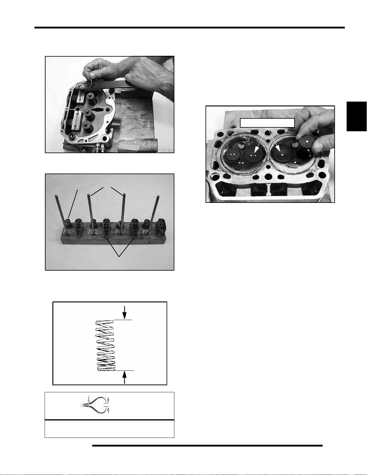
ENGINE
Cylinder Head Disassembly
1. Carefully remove the cylinder components.
2. Place the hydraulic lifters (C), pushrods (D), and rocker
arms (E) in a safe, clean area.
C
D
4. Remove valve guide seals.
IMPORTANT: It is recommended to replace seals
whenever the cylinder head is disassembled.
Hardened, cracked or worn valve seals will cause
excessive oil consumption and carbon buildup.
5. Mark the valves with a white pen. Remove the valves from
the cylinder head. This will ensure that the valves are
properly placed during engine reassembly.
Mark the Valves
3
E
3. Measure free length of spring with a Vernier caliper.
Compare to specifications. Replace spring if measurement
is out of specification.
V alve Spring
Free Length
= In. / mm.
Valve Spring Free Length:
Std: 1.735" (44.069 mm)
3.27
Page 74

ENGINE
Valve Inspection
1. Remove all carbon from valves with a soft wire wheel or
brush.
2. Check valve face for runout, pitting, and burnt spots. To
check for bent valve stems, mount valve in a drill or use “V”
blocks and a dial indicator.
3. Check end of valve stem for flaring, pitting, wear or damage
(A).
= In. / mm.
Valve Stem Diameter:
Intake: 0.2356" + 0.00039"
(5.985 + 0.01 mm)
Exhaust: 0.2351" + 0.00039"
(5.972 + 0.01 mm)
6. Measure valve guide (C) inside diameter at the top middle
and end of the guide using a small hole gauge and a
micrometer. Measure in two directions.
C
A
B
4. Inspect split keeper groove for wear or flaring of the keeper
seat area (B).
NOTE: The valves can be re-faced or end ground, if
necessary. They must be replaced if extensively
worn, burnt, bent, or damaged.
5. Measure diameter of valve stem with a micrometer in three
places, then rotate 90 degrees and measure again (six
measurements total). Compare to specifications.
Measure valve stem in several places.
Rotate the valve 90 degrees and measure
for wear.
= In. / mm.
Valve Guide I.D.:
0.23672" + 0.000295"
(6.0617 + 0.0075 mm)
7. Subtract valve stem measurement from the valve guide
measurement to obtain stem to guide clearance. NOTE:
The valve guides cannot be replaced. Be sure to measure
each guide and valve combination individually.
3.28
Page 75

ENGINE
Combustion Chamber
1. Clean all accumulated carbon deposits from combustion
chamber and valve seat area with carbon cleaner and a soft
plastic scraper.
IMPORTANT: Do not use a wire brush, metal scraper,
or abrasive cleaners to clean the bottom of the
cylinder head. Extensive damage to the cy linder head
may result. Wear safety glasses during cleaning.
Combustion Area
NOTE: Valve seat width and point of contact on the
valve face is very important for proper sealing. The
valve must contact the valve seat over the entire
circumference of the seat, a nd the seat must be the
proper width all the way around. If the seat is
uneven, compression leakage will result. If the seat
is too wide, seat pressure is reduced, causing
carbon accumulation and possible compression
loss. If the seat is too narrow, heat transfer from
valve to seat is reduced. The valve may overheat
and warp, resulting in burnt valves.
3
Valve Seat Reconditioning
NOTE: Polaris recommends that the work be done
by a local machine shop that specializes in this area.
NOTE: The cylinder head valve guides cannot be
replaced.
WARNING
Wear eye protection or a face shield during
cylinder head disassembly and reassembly.
Valve Seat Inspection
Inspect valve seat in cylinder head for pitting, burnt spots,
roughness, and uneven surface. If any of the above conditions
exist, the valve seat must be reconditioned. If the valve seat is
cracked the cylinder head must be replaced.
Follow the manufacturers instructions provided with the valve
seat cutters in the Cylinder Head Reconditioning Kit (PN
2200634). Abrasive stone seat reconditioning equipment can
also be used. Keep all valves in order with their respective seat.
1. Install pilot into valve guide.
2. Apply cutting oil to valve seat and cutter.
3. Place 46
cutter on the pilot and make a light cut.
3.29
Page 76

ENGINE
4. Inspect the cut area of the seat:
* If the contact area is less than 75% of the circumference of the
seat, rotate the pilot 180
* If the cutter now contacts the uncut portion of the seat, check
the pilot. Look for burrs, nicks, or runout. If the pilot is bent it
must be replaced.
* If the contact area of the cutter is in the same place, the valve
guide is distorted from improper installation
* If the contact area of the initial cut is greater than 75%,
continue to cut the seat until all pits are removed and a new seat
surface is evident. NOTE: Remove only the amount of material
necessary to repair the seat surface.
5. To check the contact area of the seat on the valve face, apply
a thin coating of Prussian Blue paste to the valve seat. If
using an interference angle (46
marker to the entire valve face (A).
and make another light cut.
) apply black permanent
NOTE: When using an interference angle, the seat
contact point on the valve will be very narrow, and is
a normal condition. Look for an even and
continuous contact point all the way around the
valve face (A).
B
A
Proper Seat Contact
on Valve Face
Bottom 60
Seat 45
Top 30
A
6. Insert valve into guide and tap valve lightly into place a few
times.
7. Remove valve and check where the Prussian Blue
indicates seat contact on the valve face. The valve seat
should contact the middle of the valve face or slightly
above, and must be the proper width.
* If the indicated seat contact is at the top edge of the valve face
and contacts the margin area (B) it is too high on the valve face.
Use the 30
* If too low, use the 60
area is centered on the valve face, measure seat width.
* If the seat is too wide or uneven, use both top an d bottom
cutters to narrow the seat.
* If the seat is too narrow, widen using the 45
check contact point on the valve face and seat width after each
cut.
cutter to lower the valve seat.
cutter to raise the seat. When contact
cutter and re-
Seat
Width
= In. / mm.
Valve Seat Width:
Intake Std: .028" (.7 mm)
Limit: .055" (1.4 mm)
Exhaust Std: .039I (1.0 mm)
Limit: .071" (1.8 mm)
3.30
Page 77

ENGINE
8. Clean all filings from the area with hot soapy water. Rinse
and dry with compressed air.
9. Lubricate the valve guides with clean engine oil, and apply
oil or water based lapping compound to the face of the
valve.
NOTE: Lapping is not required with an interference
angle valve job.
10. Insert the valve in to its respective guide and lap using a
lapping tool or a section of fuel line connected to the valve
stem.
Cylinder Head Reassembly
NOTE: Assemble the valves one at a time to
maintain proper order.
1. Apply engine oil to valve guides and seats.
2. Coat valve stem with molybdenum disulfide grease or
2W-50 Synthetic engine oil.
3. Install valve carefully with a rotating motion to avoid
damaging valve seal.
3
4. Valve seals should be installed after the valves are in the
head to avoid valve seal damage. Install new valve seals
on valve guides.
5. Dip valve spring and retainer in clean engine oil and install.
6. Place retainer on spring and install Valve Spring
Compressor (PU-45257). Install split keepers with the gap
even on both sides.
NOTE: A small magnet can be used to aid in the
installation of the keepers.
PU-45257
11. Rotate the valve rapidly back and forth until the cut sounds
smooth. Lift the valve slightly off of the seat, rotate 1/4
turn, and repeat the lapping process. Do this four to five
times until the valve is fully seated, and repeat process for
the other valve(s).
12. Thoroughly clean cylinder head and valves.
7. Repeat procedure for remaining valves. When all valves
are installed, tap lightly with soft faced hammer on the end
of the valves to seat the split keepers.
NOTE: To prevent damage to the valve seals, do not
compress the valve spring more than necessary to
install the keepers.
3.31
Page 78

ENGINE
Valve Sealing Test
1. Clean and dry the combustion chamber area (A).
A
2. Pour a small amount of clean solvent onto the intake port
and check for leakage around each intake valve. The valve
seats should hold fluid with no seepage.
3. Repeat for exhaust valves by pouring fluid into exhaust
port.
Cylinder Removal
1. Follow engine disassembly procedures to remove rocker
cover and cylinder head.
2. Tap cylinder (A) lightly with a rubber mallet in the
reinforced areas only until loose.
3. Rock cylinder forward and backward while lifting it from
the crankcase, supporting pistons and connecting rods.
Support pistons with Piston Support Block (PN 2870390).
Valve Lifter Removal / Inspection
1. Remove the valve lifters by reaching into the crankcase
and pushing the lifter up through the lifter bore by hand.
2. Thoroughly clean the lifters in cleaning solvent and wipe
them with a clean, lint-free cloth.
3. Mark the lifters with a white pen if using the lifters for
reassembly. This will ensure that the lifters are properly
placed during engine reassembly.
Mark Hydraulic Lifter
4. Check the lifters for wear or scores.
5. Check the bottom end of lifter to make sure that it has a
slight convex.
6. If the bottom surface has worn flat, it may be used with the
original camshaft only.
3.32
A
Inspect Hydraulic Lifter
NOTE: Lifters that are scored, worn, or if the bottom
is not smooth should be replaced with new lifters
and cam as an assembly. If replacing the lifters, the
camshaft should also be replaced.
Page 79

ENGINE
Piston Removal
1. Remove circlip (A). Mark the piston with a white pen to
ensure proper orientation (if reused) during assembly.
NOTE: If the pistons are to be reused, reassemble
the pistons in the same cylinder and direction from
which they were removed.
NOTE: New pistons are non-directional and can be
placed in either cylinder.
The oil control ring is a three piece design consisting of a top and
bottom steel rail and a center expander section. The top rail has
a locating tab on the end which fits into a notch (B) in the upper
oil ring land of the piston.
To Remove:
A) Remove the top rail first followed by the bottom rail.
B) Remove the expander.
Compression
Rings
Oil Ring
B
3
2. Remove piston circlip and push piston pin out of piston. If
necessary, heat the crown of the piston slightly with a
propane torch. CAUTION: Do not apply heat to the piston
rings. The ring may lose radial tension.
3. Remove top compression ring:
*Using a piston ring pliers: Carefully expand ring and lift it off
the piston. CAUTION: Do not expand the ring more than the
amount necessary to remove it from the piston, or the ring may
break.
*By hand: Placing both thumbs as shown, spread the ring open
and push up on the opposite side. Do not scratch the ring lands.
4. Repeat procedure for second ring.
5. Remove the oil control ring.
3.33
Page 80

ENGINE
Cylinder Inspection
1. Remove all gasket material from the cylinder sealing
surfaces.
2. Inspect the top of the cylinder (B) for warp using a straight
edge (A) and feeler gauge (C). Refer to Ill. 1 and Ill. 2.
A
B
Measure at different
points on surface.
B
A
3. Inspect cylinder for wear, scratches, or damage.
4. Inspect cylinder for taper and out of round with a
telescoping gauge or a dial bore gauge. Measure in two
different directions, front to back and side to side, on three
different levels (1/2, down from top, in the middle, and 1/
2, up from bottom). Record measurements. If cylin der is
tapered or out of round beyond .002", the cylinder must be
replaced.
1/2” Down From Top of Cylinder
C
= In. / mm.
Cylinder Warp: .004" (0.1 mm) Ma x .
1/2” Up From Bottom
= In. / mm.
Cylinder Taper Limit:
.002" (9.05mm) Max.
Cylinder Out of Round:
Limit: .002" (.0 mm) Max.
3.34
Page 81

Standard Bore Size
(Both Cylinders): 3.1496" (80 mm)
Cylinder Hone Selection and Honing Procedure
Cylinders may be wet or dry honed depending upon the hone
manufacturer’s recommendations. Wet honing removes more
material faster and leaves a more distinct pattern in the bore.
CAUTION
ENGINE
If cylinder wear or damage is excessive, it will be necessary to
replace the cylinder. The cylinders are lined with a nicasil
coating and are not repairable. Hone only enough to de-glaze
the outer layer of the cylinder bore.
3
A hone which will straighten as well as remove
material from the cylinder is very important.
Using a common spring loaded glaze breaker
for honing is not advised for nicasil cylinders.
Polaris recommends using a rigid hone or arbor
honing machine. Cylinders may be wet or dry
honed depending upon the hone manufacturer's
recommendations.
Wet honing removes more material faster and
leaves a more distinct pattern in the bore.
Honing To Deglaze
A finished cylinder should have a cross-hatch pattern to ensure
piston ring seating and to aid in the retention of the fuel/oil
mixture during initial break in. Hone cylinder according to hone
manufacturer's instructions, or these guidelines:
• Honing should be done with a diamond hone. Cylinder
scratch the nicasil lining.
• Use a motor speed of approximately 300-500 RPM, run
the hone in and out of the cylinder rapidly until cutting
tension decreases. Remember to keep the hone drive
shaft centered (or cylinder centered on arbor) and to
bring the stones approximately 1/2” (1.3 cm) above and
below the bore at the end of each stroke.
Example of Cross Hatch Pattern
IMPORTANT: Clean the cylinder after honing
If cylinder wear or damage is excessive, it will be necessary to
replace the cylinder. The cylinders are lined with a nicasil
coating and are not repairable. Hone only enough to de-glaze
the outer layer of the cylinder bore.
Cleaning the Cylinder After Honing
It is very important that the cylinder be thoroughly cleaned after
honing to remove all grit material. Wash the cylinder in a
solvent, then in hot, soapy water. Pay close attention to areas
where the cylinder sleeve meets the aluminum casting (transfer
port area). Use electrical contact cleaner if necessary to clean
these areas. Rinse thoroughly, dry with compressed air, and oil
the bore immediately with Polaris Lubricant.
• Release the hone at regular intervals and inspect the
bore to determine if it has been sufficiently de-glazed,
and to check for correct cross-hatch.
NOTE: Do not allow cylinder to heat up during honing.
• After honing has been completed, inspect cylinder for
thinning or peeling.
3.35
Page 82
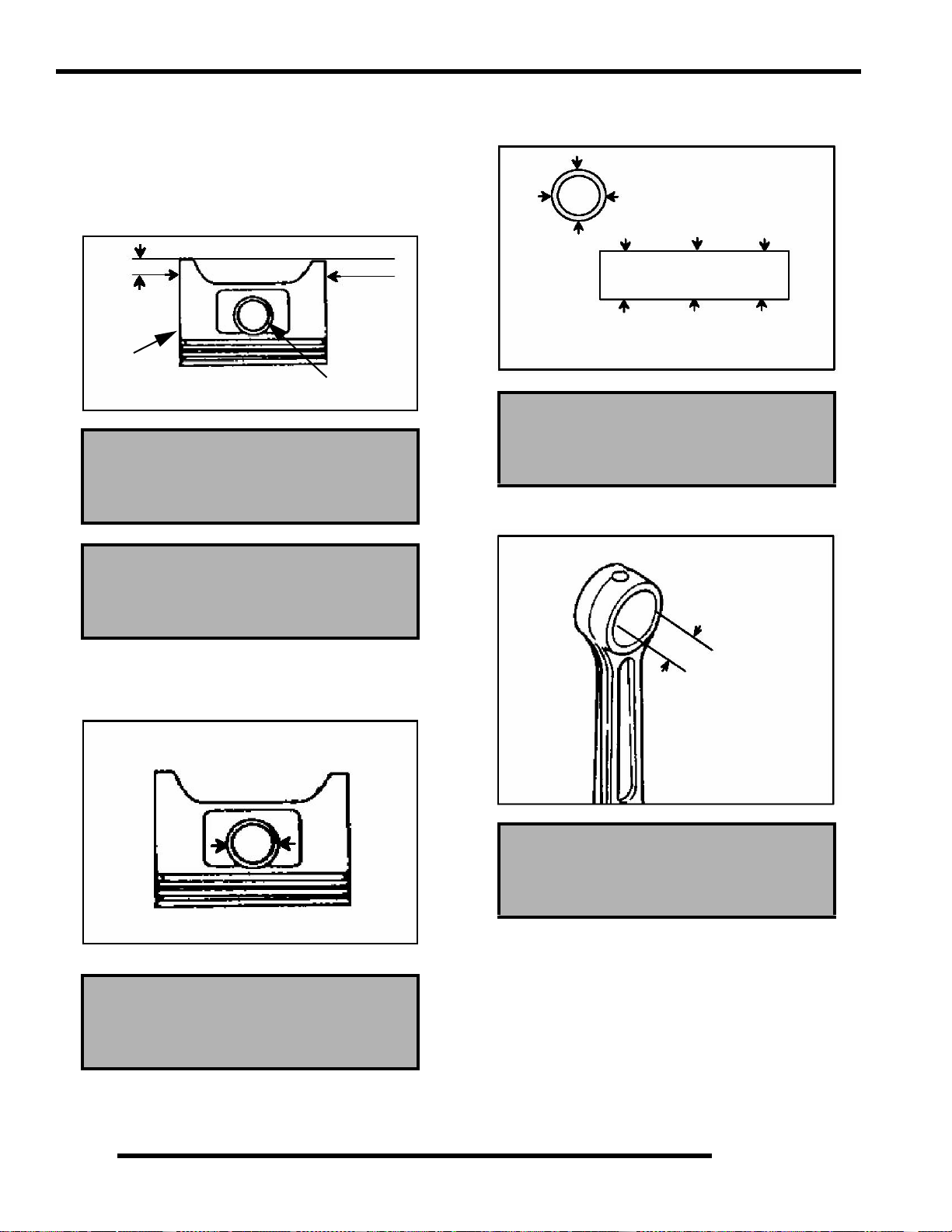
ENGINE
Piston-to-Cylinder Clearance
Measure piston outside diameter at a point 5 mm up from the
bottom of the piston at a right angle to the direction of the piston
pin.
Subtract this measurement from the maximum cylinder
measurement obtained in Step 5.
5 mm
Piston
Piston Pin
Piston to Cylinder Clearance:
See “800 EFI Engine Service
Specifications” on page 3.9
2. Measure piston pin O.D. Replace piston and/or piston pin
if out of tolerance.
Piston Pin Measurement Locations
Piston Pin O.D.:
See “800 EFI Engine Service
Specifications” on page 3.9
3. Measure connecting rod small end ID.
Piston O.D.:
See “800 EFI Engine Service
Specifications” on page 3.9
Piston / Rod Inspection
1. Measure piston pin bore.
Piston Pin Bore:
See “800 EFI Engine Service
Specifications” on page 3.9
Connecting Rod Small End I.D.:
See “800 EFI Engine Service
Specifications” on page 3.9
3.36
Page 83

ENGINE
4. Measure piston ring to groove clearance by placing the ring
in the ring land and measuring with a thickness gauge.
Replace piston and rings if ring-to-groove clearance
exceeds service limits.
Piston
Ring
Feeler Gauge
See “800 EFI Engine Service
Specifications” on page 3.9
Piston Ring Installed Gap
1. Place each piston ring (A) inside cylinder (B) using piston
to push ring squarely into place as shown.
3. If the bottom installed gap measurement exceeds the
service limit, replace the rings. If ring gap is smaller than
the specified limit, file ring ends until gap is within
specified range.
NOTE: Always check piston ring installed gap after
re-boring a cylinder or when installing new rings. A
re-bored cylinder should always be scrubbed
thoroughly with hot soapy water, rinsed, and dried
completely. Wipe cylinder bore with oil immediately
to remove residue and prevent rust.
Starter Drive Bendix Removal / Inspection
1. Remove stator housing bolts and remove housing.
2. Remove the flywheel nut and washer. Install Flywheel
Puller (PN 2871043) and remove flywheel.
NOTE: Do not thread the puller bolts into the
flywheel more than 1/4, or stator coils may be
damaged.
3. Remove starter bendix assembly (A). Note the thrust
washers located on both sides of the bendix.
A
3
C
B
A
25-50 mm
Piston Ring Installed Gap
See “800 EFI Engine Service
Specifications” on page 3.9
NOTE: Ring should be installed with the mark facing
upward.
2. Measure installed gap with a feeler gauge (C) at both the
top and bottom of the cylinder.
IMPORTANT: A difference in end gap indicates
cylinder taper. The cylinder should be measured for
excessive taper and out of round.
4. Inspect the thrust washer for wear or damage and replace
if necessary.
5. After the bendix is removed, remove t he two bolts retaining
the starter. Tap on the starter assembly (B) with a soft faced
mallet to loosen the starter from the crankcase.
B
3.37
Page 84

ENGINE
6. Inspect gear teeth on starter drive (A). Replace starter drive
if gear teeth are cracked, worn, or broken.
7. Inspect the bendix bushing (C) in the mag cover for wear.
Replace as needed.
C
Flywheel / Stator Removal / Inspection
1. Remove stator housing bolts and remove housing.
Remove Stator
Cover
2871043
4. Use caution when removing the wire holddown (B) and th e
stator assembly (D). Do not tap or bump the gear /stator
housing cover or the stator. This could cause the seal
around the gear/stator housing cover and the crankcase to
break, causing a leak.
E
A
D
B
5. Remove the bendix (E) if necessary.
2. Remove flywheel nut and washer.
3. Install Flywheel Puller (PN 2871043) and remove flywheel
(A).
CAUTION
Do not thread the puller bolts into the flywheel
more than 1/4, or stator coils may be damaged .
3.38
Engine Crankcase Disassembly / Inspection
1. Remove the stator cover (A) and water pump cover (B).
B
A
Page 85
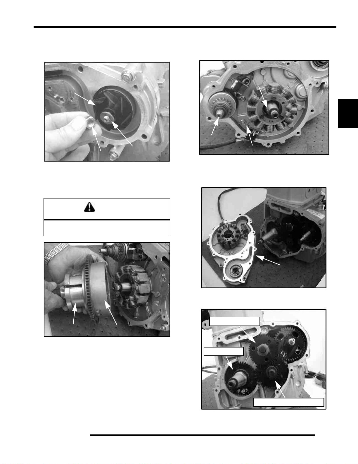
ENGINE
2. Remove the nylok nut (C), washer (D), and water pump
impeller (E). Remove part of the water pump seal behind
the impeller.
E
D
C
3. Remove flywheel nut and washer.
4. Install Flywheel Puller (PN 2871043) and remove flywheel
(F).
CAUTION
5. Remove the starter bendix (G), wire holddown plate (H),
and the woodruff key (I) from the crankshaft. The stator
does not have to be removed at this point.
I
3
G
H
6. Remove the gear/stator housing bolts and remove the gear/
stator housing cover (J) and gasket from the crankcase. Be
sure to catch the excess oil from the crankcase.
Do not thread the puller bolts into the flywheel
more than 1/4, or stator coils may be damaged.
2871043
F
J
7. Note the positions of the gears in the photo.
Camshaft Gear
Crank Gear
Counterbalance Gear
3.39
Page 86

ENGINE
8. Use a white pen to accent the timing marks on the following
gears: camshaft gear (K), crankshaft gear (M), or
counterbalance gear (N) This will ensure proper gear
alignment and timing during reassembly of the gears.
K
Water Pump Gear
Timing Marks
CAUTION
Wear safety glasses at all times. Use caution
when working with the top gear.
The springs could cause injury or become lost
should they pop out.
12. Remove all three springs using one of the tapered pins from
the Tapered Pins (PU-45497-1).
M
N
NOTE: If replacing one of the gears, it is
recommended that all of the gears be replaced. A
gear kit is available.
9. Use the Cam Gear Tooth Alignment Tool (PU-45497-2)
(O) to align the cam split gear assembly. With the split gear
aligned, remove the bolt and cam gear assembly.
NOTE: Install the Cam Gear Tooth Alignment Tool
(PU-45497-2) into the assembly hole counter
clockwise from the timing mark as shown.
10. Inspect the cam gear teeth and check to make sure there is
spring tension offsetting the teeth between the two gears.
If there is no tension, check the springs inside of the cam
gear assembly.
3 Loaded Springs
PU-45497-1
13. With a white marking pen, accent the timing mark on the
gear that contains the springs.
11. The cam gear assembly contains three loaded springs. To
open the cam gear assembly:
• Place the cam gear on a flat surface with the timing
mark side facing up.
• While holding both gears together, lightly work a small
flathead screwdriver between the two gears.
• Remove the top gear. The springs should stay in place.
3.40
Accent Timing Marks
Page 87
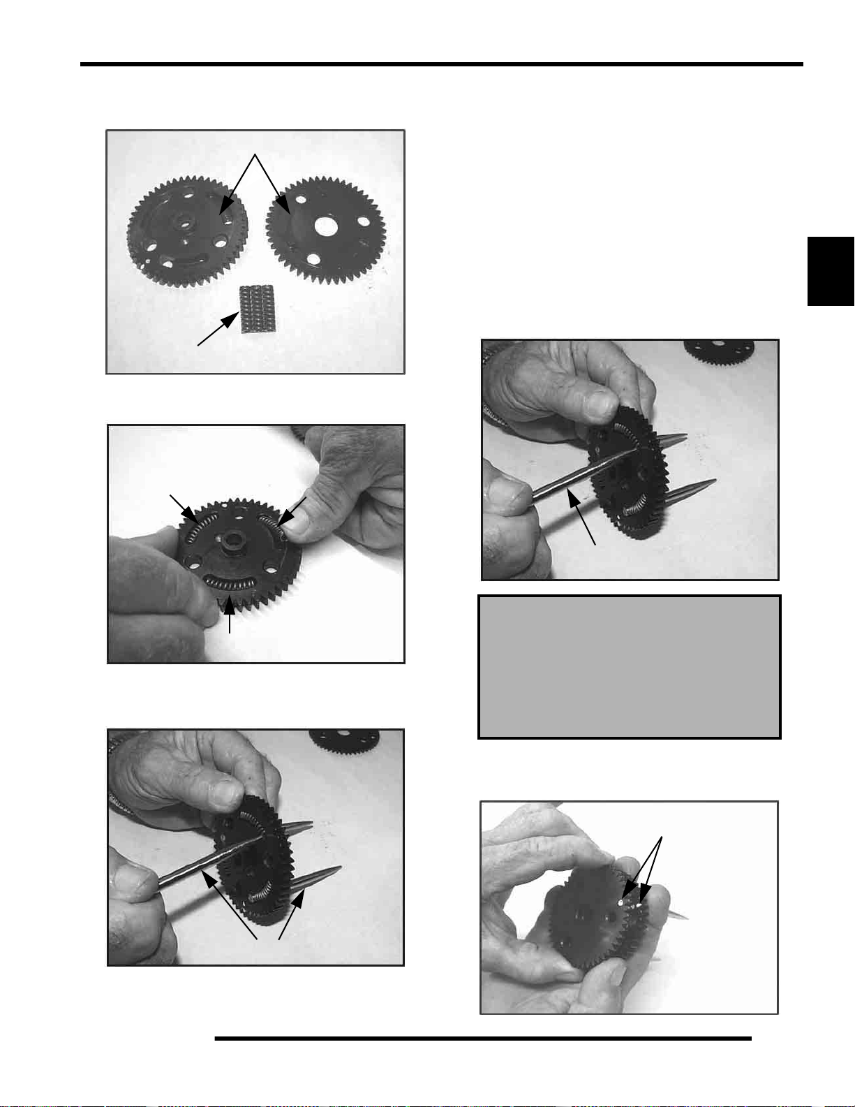
ENGINE
14. Inspect the gear teeth and the three tabs on the gears for
wear.
Inspect Teeth & Tabs
Replace 3 Springs
15. Install the new springs into the grooves of the cam gear.
Install Springs
To Assemble:
• Hold the spring with one finger.
• Start the pointed end of the tapered pin into the cam
gear hole. Slowly push the dowel through the hole until
the end of the dowel is almost flush with the spring.
• Perform this procedure with all three tapered pins.
• Do not push the pins too far through or the springs will
pop out.
NOTE: Do not remove the tapered pins at this time.
17. Note in photograph that the Tapered Pins (PU-45497-1)
are below flush with end of the springs. This helps to align
the three gear tabs during the next step.
3
16. Insert the pointed dowels from the Tapered Pins (PU45497-1) into the cam gear.
PU-45497-1
PU-45497-1
Cam Gear Spring Installation Tool Kit:
(PU-45497)
Tapered Pins:
(PU-45497-1)
Cam Gear Tooth Align Tool:
(PU-45497-2)
18. Line up the two gears using the timing marks and the three
gear tabs that were referenced earlier. Push the gears back
together, using both hands and hold securely.
Align Timing Marks
3.41
Page 88
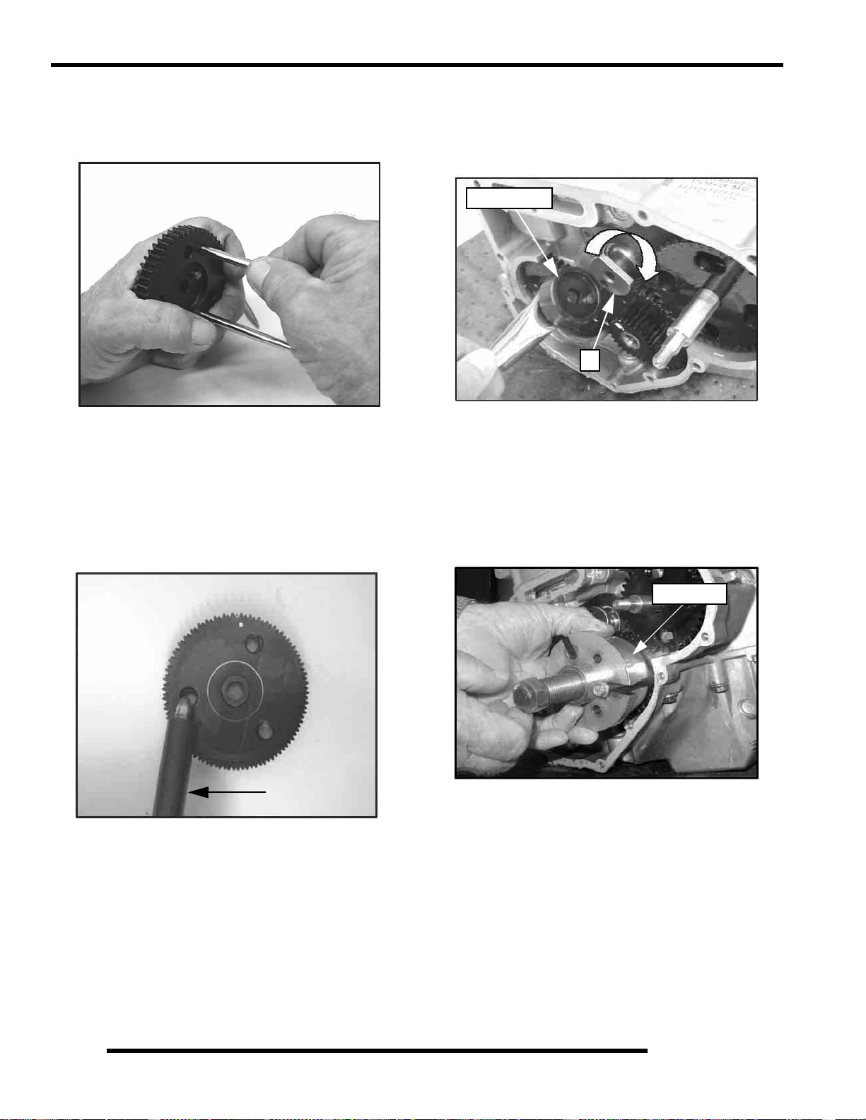
ENGINE
19. Once the gears are pressed together, firmly hold the gears
together with one hand. Carefully remove the Tapered Pins
(PU-45497-1) by pulling them out one at a time with the
other hand.
20. After the tapered pins are removed, be sure the cam gear
assembly is held together tightly. Place the cam gear
assembly on a flat surface. Use the Cam Gear Tooth
Alignment Tool (PU-45497-2) to align the teeth of the cam
gears, as shown in the picture.
NOTE: Install the Cam Gear Alignment Tool (PU45497-2) into one assembly hole counter clockwise
from the timing mark.
21. To remove the balance shaft gear, the flat side of the
camshaft (P) must face the balance shaft gear. To rotate the
camshaft, use the Cam Spanner Wrench (PU-45498) to
rotate the camshaft so the flat side of the camshaft faces the
balance shaft gear.
PU-45498
P
NOTE: This Cam Spanner Wrench (PU-45498) is
only needed to rotate the camshaft when the entire
valve train is assembled. If the rocker arms are
removed, the cam-shaft can be turned by hand.
22. Remove the bolt an d nut from the balance shaft gear. Try
to remove the balance shaft gear. If the gear does not come
off manually, use the Flywheel Puller (PN 2871043) to
remove the balance shaft gear.
PU-45497-2
NOTE: For ease of installing the Cam Gear
Alignment Tool (PU-45497-2), use a twisting motion
when pushing down on the tool.
2871043
3.42
Page 89

ENGINE
23. Inspect the crankshaft gear (Q) for broken or worn teeth. If
the crankshaft gear does not need to be replaced, it does not
need to be removed. If the crankshaft gear is damaged,
remove the crankshaft gear with the Flywheel Puller
(PN 2871043).
Q
24. Install the two puller bolts (R). Tighten the puller bolts up
so that the bolts are at equal length.
R
26. Rotate the water/oil pump gear (S), so that all four bolts are
visible though the gear. Remove the four bolts with a hex
wrench. Pull out the pump.
S
3
27. Inspect the oil pump rotors for wear. Mark the rotors with
a white pen to ensure upon reassembly that the correct sides
of the rotors are installed and mesh with the same edges as
previously installed.
Mark Rotors
25. Install the Flywheel Puller (PN 2871043) and remove the
crankshaft gear, if needed.
2871043
NOTE: If replacing the old rotors, new replacement
rotors will fit into the original oil/water pump
housing.
28. Use a feeler gauge to measure the clearance between the
two rotors. Measure the gap between the two rotor tips as
shown below. The clearance should not exceed 0.006"
(0.15 mm).
Max Tip Clearance
0.006” (0.15 mm)
3.43
Page 90

ENGINE
29. Remove the oil pressure relief. The oil pressure relief
consists of a bolt, washer, spring, and valve (dowel).
Inspect the valve (dowel) for signs of possible obstructions.
Use compressed air to blow out any debris.
30. Reinstall the valve (dowel chamfered end first). Install the
spring, washer, and bolt. Torque to specification .
22 ± 2 ft. lbs.
(30 ± 3 Nm).
31. Carefully press the gear off the assembly while supporting
the housing assembly.
Press Off Gear
CAUTION
Wear appropriate safety gear during this
procedure. Protective gloves, clothing and eye
wear are required.
32. Remove the snap ring from the assembly. Place the housing
in a support and press out the bearing/shaft assembly.
Chamfer
End First
= T
22 2 ft. lbs. (30 3 Nm)
NOTE: Be sure to place the tapered en d of the va lve
(dowel) in first. If the valve is installed incorrectly,
oil pressure and oil priming problems will occur.
Press out shaft
and bearing
assembly.
Bearing
Retaining Ring
33. Place the shaft in a press to remove the bearing.
Press Off Bearing
3.44
Page 91

ENGINE
34. Press shaft into the new bearing..
Press On Bearing
35. Press the bearing/shaft assembly using the bearing's outer
race. Do not use the shaft to press the assembly into the
housing, as bearing damage may result. Install retaining
ring.
Press Bearing / Shaft
Assembly using
outer race only
37. Remove thrust plate (U).
U
3
38. Remove PTO end engine mount. Remove crankcase bolts.
Tap on the reinforced areas on the cases using soft hammer.
Carefully separate the two crankcase halves.
Separate
Crankcase Halves
36. Press gear onto shaft while supporting the housing.
NOTE: Only remove the oil baffle if the baffle is
damaged. When removing the oil baffle bolts, use a
heat gun to heat the bolts and loosen the Loctite
This will prevent any possible damage to the bolt s or
to the crankcase casting.
.
3.45
Page 92

ENGINE
39. Remove and clean oil pick up (V) and oil baffle weldment
(W).
W
V
40. Remove balance shaft and crankshaft.
Camshaft Inspection
1. Thoroughly clean the cam shaft.
2. Visually inspect each cam lobe for wear, chafing or
damage.
3. Measure height of each cam lobe using a micrometer.
Compare to specification.
Cam Lobe Height
41. Remove and inspect crankshaft m ain journal bearings for
abnormal wear. It is recommended to replace the
bearings anytime the engine is disassembled.
= In. / mm.
Cam Lobe Height
Intake (Std):
800 EFI: 1.334" (33.867 mm)
800 H.O. EFI: 1.357” (34.477 mm)
Exhaust (std.):
800 EFI: 1.334" (33.867 mm)
800 H.O. EFI: 1.342” (34.096 mm)
3.46
Page 93

ENGINE
4. Measure camshaft journal outside diameters (O.D.).
C
B
A
= In. / mm.
Camshaft Journal O.D. :
A. (Mag): 1.654" ± .00039" (42 ± .010 mm)
B. (Ctr.): 1.634" ± .00039" (41.50 ± .010 mm)
C. (PTO): 1.614" ± .00039" (41 ± .010 mm)
ENGINE REASSEMBLY
Crankcase Reassembly
CAUTION
After any reassembly or rebuild, the engine
must be primed using the Oil Priming Adapter
(PU-45778) and a 3/4-full oil filter before initial
start-up (see “Oil Pump Priming”).
3
NOTE: Before assembly, clean the bolts and bolt
holes with Primer N (PN 2874275) to remove any
debris. This will ensure proper sealing when
installing bolts.
1. Install oil pick up (A), if removed. Torque to specification.
B
A
5. Measure ID of camshaft journal bores.
= In. / mm.
Camshaft Journal Bore I.D.:
(Mag): 1.656" ± 0.00039" (42.07± 0.010 mm)
(Ct r. ) 1.637" ± 0 .00039" (4 1.58 ± 0.01 0 m m)
(PTO) 1.617" ± 0.00039" (41.07 ± 0.010 mm)
6. Calculate oil clearance by subtracting journal O.D.s from
journal bore I.D.s. Compare to specificati o n.
= In. / mm.
Calculated Camshaft Oil Clearance:
Std: 0.0027" (.070mm)
Limit: .0039" (.10 mm)
NOTE: Replace camshaft if damaged or if any part is
worn past the service limit.
2. Install oil baffle weldment (B). Torque bolts to
specification.
= T
Oil Baffle Weldment & Oil Pick Up Bolt Torque:
60 ± 6 in. lbs. (6.8 ± 0.68 Nm)
3. Install the balance shaft. Inspect balance shaft clearance
(C) in both gearcase halves. Rotate balance shaft to ensure
there is clearance between it and the oil baffle weldment.
C
NOTE: Replace engine block if camshaft journal
bores are damaged or worn excessively.
3.47
Page 94

ENGINE
NOTE: Always install new balance shaft bearings.
4. Apply assembly lube to cam journals and balance shaft
bearing surfaces of the MAG case halve. Install camshaft
and balance shaft.
5. Install crankshaft assembly and apply engine oil to crank
pins and rods (D). Apply assembly lube to the main
journals and bearings.
7. Assemble the crankcase halves. Apply LocTite™ 242 (PN
2871949) to the threads and pipe sealant to the bolt flanges.
Torque bolts to specification following torque pattern at
beginning of this chapter.
= T
Crankcase Bolt Torque:
22 + 2 ft. lbs. (30 + 3 Nm)
Torque in sequence
8. Lubricate cam lobes and valve lifters with Moly Lube
Grease.
Apply Moly Lube
Cam Lobes
D
6. Apply Crankcase Sealant (PN 2871557) to the top gearcase
halve.
NOTE: Do not apply sealant to cam relief hole (E).
E
Lifters
9. Lubricate lifters with engine oil and install in the original
order as removed in disassembly. Apply Lubricant or Moly
Lube to the ends of the lifters.
NOTE: Always re place the camshaft and lifters as a
set.
3.48
Page 95

ENGINE
10. Lubricate connecting rods with 2W-50 synthetic engine oil.
11. Install new cylinder gasket on crankcase. Align gasket on
the dowel pins for proper gasket alignment.
13. Install piston assemblies into cylinder alig ning the piston
pin holes, to ensure proper alignment of the pistons to the
connecting rods upon assembly. Partially install the piston
pins into the pistons.
3
NOTE: To help align the pistons, slide a rod that is
close to the same diameter as the wrist pin holes to
properly align them in the cylinder.
14. Position cylinder and piston assemblies onto the connecting
rods and push the piston pins through the piston and
connecting rods.
12. Orientate the piston rings on the piston before inst allation
into the cylinders. Set the gaps of the rings every 120°
(See Illustration Below).
1
Piston Ring
Orientation
1. Top Ring
2. Second Ring
3. Oil Ring
2
3
Push in Piston Pins
15. Install the piston pin circlips. The circlip ends should be
installed at the 12 O'clock position.
Piston Pin Cirlcip in
12 O’clock position
3.49
Page 96

ENGINE
NOTE: While installing in piston circlips, cover all
engine passages. The clip could fall into the engine
during installation.
16. Install camshaft thrust plat e (G) with new bolts. Torque
bolts to specification.
NOTE: New bolts have patch lock on the threads
and do not require Loctite™.
17. Assemble rotors as marked when disassembled. Use a
cleaner to remove the marks previously made on the rotors.
Line Up Marks
18. Apply assembly lube or oil to the rotors on the oil pump
shaft.
NOTE: The application of lubrication aids in priming
the oil pump during initial engine start up.
Lubricate Rotors
G
= T
Thrust Plate Screw Torque:
115 ± 12 in.lbs. (13 ± 1.35 Nm)
19. Align the bolt holes and install oil pump assembly into
crankcase. Rotate the rotors in the housing during
installation, as this checks for binding if new rotors are
used.
NOTE: For assembly of the gears, the cam gear and
the crankshaft gear are stamped with “This Side
Out." This indicates the side of the gear that faces
outward or away from the case.
3.50
NOTE: Before assembly, clean the bolts and bolt
holes with Primer N (PN 2874275) to remove any
debris. This will ensure proper sealing when
installing bolts and new Loctite™.
Page 97

ENGINE
20. Install oil pump housing bolts (H). The new bolts contain
patch lock, so Loctite
Torque bolts to specification and follow the torque
sequence at beginning of the chapter.
is not needed on the new bolts.
H
NOTE: Occasionally spin the oil pump when
installing bolts to check for binding of the rotors.
= T
Oil Pump Bolt Torque:
84 8 in.lbs. (9.50 0.90 Nm)
* Torque in Sequence
21. Apply Loctite 242 (PN 2871949) to the crankshaft.
22. Before installing the crankshaft gear (I), heat the crankshaft
gear to 250
F (121C) on a hot plate (J).
I
J
CAUTION
The crankshaft gear is extremely hot! Severe
burns or injury can occur if the gear is not
handled with extreme care and caution. Follow
the procedure below to help ensure safety.
23. Use extreme caution when removing the crankshaft gear
from the hot plate. Use a pair of pliers and leather gloves
when handling the crankshaft gear.
24. Install the crankshaft gear (I) onto the crankshaft.
3
NOTE: For assembly of the gears, the cam gear and
the crankshaft gear are stamped with This Side Ou t."
This indicates the side of the gear that f aces outwar d
or away from the case.
I
3.51
Page 98

ENGINE
25. Install counter balance shaft gear (J) with new key, aligning
timing marks with crankshaft gear (I). Install washer and
bolt. Use the Gear Holder (PU-45838). Torque to
specification.
J
I
PU-45838
= T
Balance Shaft Gear Bolt Torque:
22 2 ft. lbs. (30 3 Nm)
NOTE: Cam Spanner Wrench (PU-45498) is only
needed to rotate the camshaft when the entire valve
train is assembled.
PU-45498
27. Reinstall the camshaft gear; so the timing marks are
properly aligned. Install the washer and bolt. Torque to
specification.
NOTE: Be sure all of the timi ng marks are properly
aligned.
26. Use the Cam Gear Alignment Tool (PU-45497-2) to align
the teeth of the cam gear (M). Install the cam gear (M) (with
the Cam Gear Alignment Tool still in place) onto the
camshaft. The timing marks on the camshaft gear should
align with the keyway on the balance shaft gear.
PU-45497-2
M
NOTE: If the timing mark on the camshaft gear does
not align properly, remove the camshaft gear and
tool. Use the Cam Spanner Wrench (PU-45498) to
rotate the cam to the proper position.
Timing Marks
M
K
Water Pump Gear
Timing Marks
N
3.52
= T
Counterbalance Gear and Camshaft
Gear Bolt Torque:
22 2 ft. lbs. (30 3 Nm)
Page 99
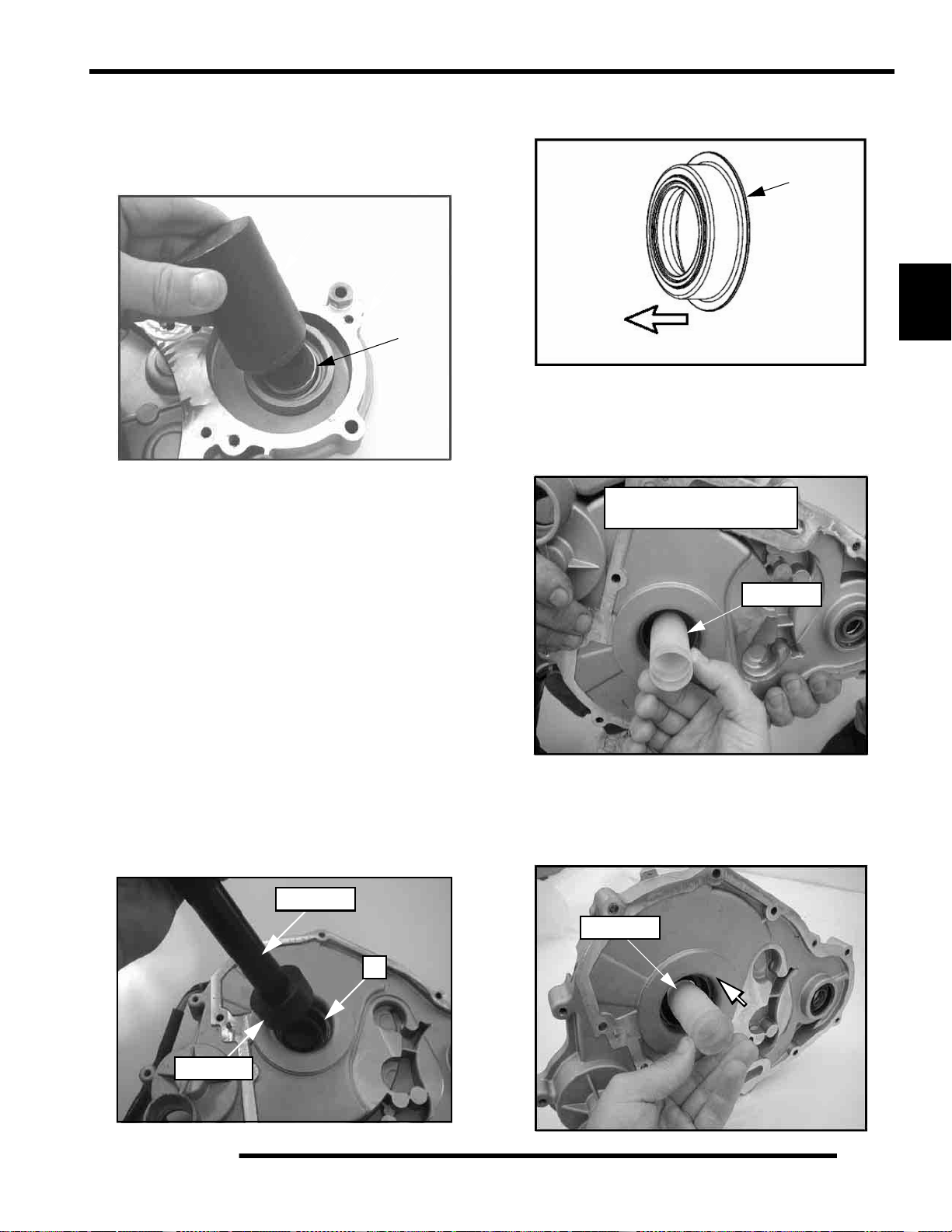
ENGINE
28. Before installing the gear / stator housing, replace the seals
in the cover. Install a new water pump seal (N) into the gear
/ stator housing. Use the Water Pump Mechanical Seal
Installer (PA-44995) to properly install the seal to the
correct depth in the cover.
PA-44995
P
A
-
4
4
9
9
5
IMPORTANT: Due to seal design and construction,
seals MUST be installed DRY (no lubricant) during
assembly. Use of lubricants (oil, soapy water, etc.)
will not allow the seal to wear-in and seal properly. Do
not touch seal surface or allow seal surface to come
in contact with contaminates during installation.
Thoroughly clean parts, tools and hands before
installation.
N
NOTE: Install the crankshaft seal (P) with the seal lip
facing out (towards the crankcase).
P
3
Seal lip goes towards the crankcase.
30. Once the crankshaft seal is installed into the gear / stator
housing cover, set the direction of the paper lip by sliding
the Main Crankshaft Seal Saver (PA-45658) into the
crankshaft seal from the rubber lipped side to the paper lip
side (Back to Front). Remove the tool.
Important: Set the direction
of the paper lip seal
PU-45658
NOTE: To remove the water pump seal, the gear/
stator housing must be removed. The water pump
seal cannot be removed or installed with the gear/
stator housing attached to the engine. Shaft damage
will occur.
NOTE: Install the water pump seal (N) with the seal
lip facing out (towards the crankcase). Use of a
hydraulic press is recommended for this procedure.
29. Install a new crankshaft seal (P) into the gear/stator housing
cover. Use the Universal Driver Handle (PU-45543) and
the Main Seal Installer (PA-45483) to seat the crankshaft
seal into place.
PU-45543
P
PA-45483
31. Carefully install the tapered end of the Crankshaft Seal
Protection Tool (PA-45658) through the paper side of the
crankshaft seal (Back to Front). Leave the seal protector
installed in the crankshaft seal. Check the crankshaft seal
lips to verify they have not been rolled or damaged.
PU-45658
3.53
Page 100

ENGINE
32. Before installing the gear/stator housing cover, inst all the
Water Pump Seal Saver (PA-45401) onto the water pump
shaft.
PA-45401
33. Install a NEW gasket to the gear/stator housing cover and
crankcase. With the tools installed, carefully place the
gear/stator housing cover over the protection tools.
35. Install the gear/stator housing gasket onto he crankcase.
Gear / Stator
Housing Gasket
34. Apply Crankcase Sealant (PN 2871557) to the outside
edges of the crankcase halves (see arrows), where the
crankcases mate (see the following photos). This helps to
prevent coolant leakage.
36. Secure the gear / stator housing cover to the crankcase with
the cover bolts. Torque bolts in proper sequence to
specification. Remove seal protectors from the shaft ends
once the cover is secure.
PA-45401
PA-45658
= T
Gear/Stator Housing Bolt Torque:
96 3 in. lbs. (10.85 0.35 Nm)
*Torque in proper sequence
3.54
 Loading...