

Page 1
Page 2

Pantone 426C
Improper vehicle use can result in SEVERE INJURY or DEATH.
NEVER Operate:
At speeds too fast for your skills or the conditions.
After or while using Alcohol or Drugs.
On hills steeper than 15 degrees 15 .
On public roads. A collision can occur with another vehicle.
With more than two passengers on the 4X4 or 6X6, with more than
5 passengers on the CREW, or with passengers under age twelve or
who cannot comfortably reach the floor and hand holds.
On paved surfaces - pavement may seriously affect handling
and control.
With non-Polaris approved accessories - they may seriously affect
stability.
ALWAYS:
Wear your seat belt. Vehicle rollover could cause severe injury or
death.
Wear a helmet and eye protection and keep hands and feet in vehicle
at all times.
Reduce speed and use extra caution when carrying passengers.
Avoid sharp turns or turns while applying heavy throttle.
Operate slowly in reverse - avoid sharp turns or sudden braking.
Make sure passenger reads and understands all safety labels.
Watch for branches or other hazards that could enter vehicle.
READ OWNER'S MANUAL.
FOLLOW ALL INSTRUCTIONS AND WARNINGS.
For your nearest Polaris dealer,
call 1-800-POLARIS
or visit www.polarisindustries.com
Polaris Sales Inc.,
2100 Hwy. 55, Medina, MN 55340
Phone 1-888-704-5290
Part No. 9922522 Rev 02
Printed in USA
Page 3
WARNING
Read, understand, and follow all of the instructions and safety precautions in
this manual and on all product labels.
Failure to follow the safety precautions could result in serious injury or death.
WARNING
The engine exhaust from this product contains chemicals known to the State
of California to cause cancer, birth defects or other reproductive harm.
Page 4

The text is printed on 100% recycled
with 40% post-consumer waste (PCW).
Page 5

WELCOME
Thank you for purchasing a Polaris vehicle, and welcome to our worldwide family of Polaris owners. We proudly produce an exciting line of
utility and recreational products.
• Snowmobiles
• All-terrain vehicles (ATVs)
• RANGER
• Victory Motorcycles
We believe Polaris sets a standard of excellence for all utility and recre-
ational vehicles manufactured in the world today. Many years of experience have gone into the engineering, design, and development of your
Polaris vehicle, making it the finest machine we’ve ever produced.
For safe and enjoyable operation of your vehicle, be sure to follow the
instructions and recommendations in this owner’s manual. Your manual
contains instructions for minor maintenance, but information about
major repairs is outlined in the Polaris Service Manual and should be
performed only by a Factory Certified Master Service Dealer
Technician.
Your Polaris dealer knows your vehicle best and is interested in your
total satisfaction. Be sure to return to your dealership for all of your service needs during, and after, the warranty period.
We also take great pride in our complete line of apparel, parts and accessories, available through our online store at www.purepolaris.com. Have
your accessories and clothing delivered right to your door!
®
utility vehicles
®
®
(MSD)
1
Page 6

POLARIS, POLARIS THE WAY OUT, RANGER, RANGER XP and RANGER
CREW are registered trademarks of Polaris Industries Inc.
Copyright 2009 Polaris Sales Inc. All information contained within this publication is
based on the latest product information at the time of publication. Due to constant
improvements in the design and quality of production components, some minor discrepancies may result between the actual vehicle and the information presented in this publication. Depictions and/or procedures in this publication are intended for reference use
only. No liability can be accepted for omissions or inaccuracies. Any reprinting or reuse
of the depictions and/or procedures contained within, whether whole or in part, is
expressly prohibited.
Printed in U.S.A.
2010 RANGER XP/HD / RANGER 6X6 / RANGER CREW Owner’s Manual
P/N 9922522
2
Page 7

TABLE OF CONTENTS
Introduction . . . . . . . . . . . . . . . . . . . . . . . . . . . . 4
Safety . . . . . . . . . . . . . . . . . . . . . . . . . . . . . . . . . 7
Features and Controls . . . . . . . . . . . . . . . . . . . 22
Operation . . . . . . . . . . . . . . . . . . . . . . . . . . . . . 41
Emission Control Systems . . . . . . . . . . . . . . . 61
Maintenance . . . . . . . . . . . . . . . . . . . . . . . . . . . 62
Specifications. . . . . . . . . . . . . . . . . . . . . . . . . 110
Polaris Products. . . . . . . . . . . . . . . . . . . . . . . 116
Troubleshooting . . . . . . . . . . . . . . . . . . . . . . . 117
Declaration of Conformity . . . . . . . . . . . . . . . 121
Warranty . . . . . . . . . . . . . . . . . . . . . . . . . . . . . 122
Maintenance Log . . . . . . . . . . . . . . . . . . . . . . 129
Index . . . . . . . . . . . . . . . . . . . . . . . . . . . . . . . . 132
3
Page 8

INTRODUCTION
The RANGER is an off-road vehicle. Familiarize yourself with all laws
and regulations concerning the operation of this vehicle in your area.
The following signal words and symbols appear throughout this manual
and on your vehicle. Your safety is involved when these words and symbols are used. Become familiar with their meanings before reading the
manual.
The safety alert symbol indicates a potential personal injury hazard.
WARNING
A WARNING indicates a hazardous situation which, if not avoided, may result in
death or serious injury.
CAUTION
A CAUTION indicates a hazardous situation which, if not avoided, may result in
minor or moderate injury.
NOTICE
A NOTICE indicates a situation that may result in property damage.
The Prohibition Safety Sign indicates an action NOT to take in order
to avoid a hazard.
The Mandatory Action Sign indicates an action that NEEDS to be
taken to avoid a hazard.
4
Page 9

INTRODUCTION
WARNING
Failure to follow the warnings contained in this manual can result in severe
injury or death.
A Polaris RANGER is not a toy and can be hazardous to operate. This vehicle
handles differently than other vehicles, such as motorcycles and cars. A collision
or rollover can occur quickly, even during routine maneuvers like turning, or
driving on hills or over obstacles, if you fail to take proper precautions.
• Read this owner’s manual. Understand all safety warnings, precautions and
operating procedures before operating the vehicle. Keep this manual with the
vehicle.
• This vehicle is an ADULT VEHICLE ONLY. NEVER operate this vehicle if you
are under age 16 and NEVER operate without a valid driver’s license.
• No person under the age of 12 may ride as a passenger in this vehicle. Any
passenger must be able to comfortably reach the floor and hand holds.
• Never permit a guest to operate this vehicle unless the guest has read this
manual and all product labels.
5
Page 10
INTRODUCTION
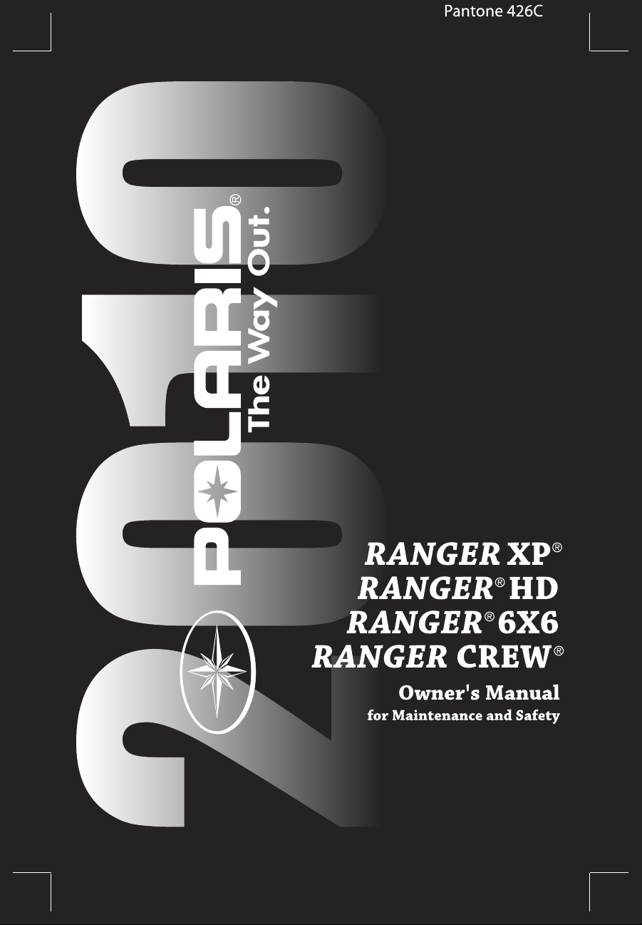
Engine Serial Number
Key
Number
VIN (4X4, 6X6)
####
VIN (Crew)
Vehicle Identification Numbers
Record your vehicle's identification numbers and key number in the
spaces provided. Remove the spare key and store it in a safe place. An
ignition key can be duplicated only by ordering a Polaris key blank
(using your key number) and mating it with one of your existing keys.
The ignition switch must be replaced if all keys are lost.
Vehicle Model Number: ___________________________________________________
Frame VIN: ____________________________________________________________
Engine Serial Number: ___________________________________________________
Key Number ____________________________________________________________
6
Page 11
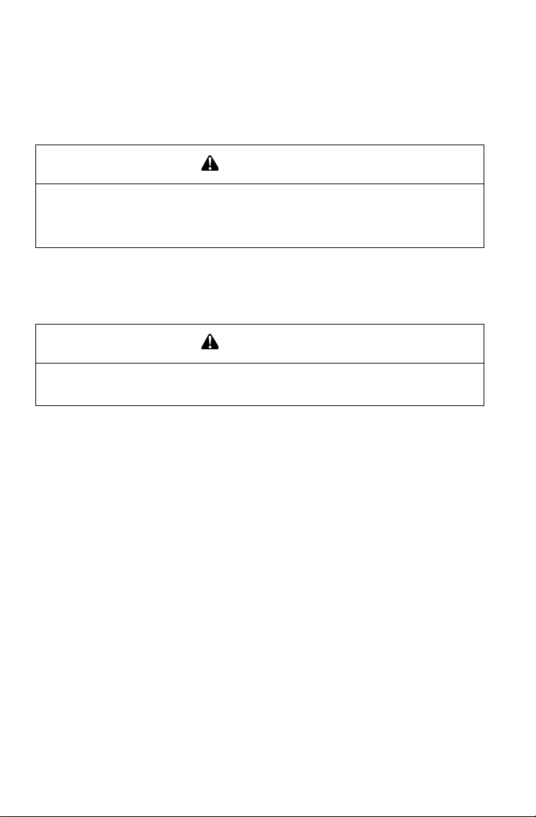
SAFETY
+
Safety Labels and Locations
Warning labels have been placed on the vehicle for your protection.
Read and follow the instructions of the labels on the vehicle carefully. If
any of the labels depicted in this manual differ from the labels on your
vehicle, always read and follow the instructions of the labels on the
vehicle.
If any label becomes illegible or comes off, contact your Polaris dealer
to purchase a replacement. Replacement safety labels are provided by
Polaris at no charge. The part number is printed on the label.
Container/Passenger/Tire Pressure Warning (4X4, 6X6)
WARNING
Remove flammable material containers from
box before filling.
• Passengers can be thrown off. This can
cause serious injury or death.
• Never carry passengers in cargo box.
Maximum 4X4 Box Load 1000 lbs. (455 kg)
Maximum 6X6 Box Load 1250 lbs. (567 kg),
Storage Box Load 250 lbs. (113 kg)
IMPROPER TIRE PRESSURE OR
OVERLOADING can cause loss of control
resulting in SEVERE INJURY OR DEATH.
TIRE PRESSURE IN PSI (KPa):
RANGER - 4X4 FRONT 10 (69) REAR 10 (69)
RANGER - 6X6 FRONT 10 (69) CENTER 10 (69) REAR 10 (69)
MAXIMUM WEIGHT CAPACITY INCLUDES WEIGHT OF OPERATOR,
PASSENGER, CARGO, AND ACCESSORIES.
RANGER 4X4 is 1500 LBS. (682 KG)
RANGER 6X6 is 2000 LBS. (907 KG)
Reduce speed and allow greater distance for braking when carrying cargo.
Overloading or carrying tall, off-center, or unsecured loads will increase your risk
of losing control. Loads should be centered and carried as low as possible in
box. For stability on rough or hilly terrain, reduce speed and cargo. Be careful if
load extends over the side of the box.
Read Owner's Manual for more detailed loading information.
7176334
7
Page 12

SAFETY
Safety Labels and Locations
Container/Passenger/Tire Pressure Warning (Crew)
WARNING
Remove flammable material containers from box before filling.
WARNING
Passengers can be thrown off. This can cause serious injury or death.
Never carry passengers in cargo box.
WARNING
Multi-Passenger Maximum Box Load 1000 lbs. (455 kg)
WARNING
IMPROPER TIRE PRESSURE OR OVERLOADING can cause loss of control
resulting in SEVERE INJURY OR DEATH.
TIRE PRESSURE IN PSI (KPa):
MULTI-PASSENGER - FRONT 12 (83) REAR 16 (110)
MAXIMUM WEIGHT CAPACITY INCLUDES WEIGHT OF OPERATOR,
PASSENGERS, CARGO, AND ACCESSORIES.
MULTI-PASSENGER is 1750 LBS. (795 KG)
Reduce speed and allow greater distance for braking when carrying cargo.
Overloading or carrying tall, off-center, or unsecured loads will increase your risk
of losing control. Loads should be centered and carried as low as possible in
box. For stability on rough or hilly terrain, reduce speed and cargo. Be careful if
load extends over the side of the box.
Read Owner's Manual for more detailed loading information.
7175214
8
Page 13
SAFETY
Clutch Cover
Warning
Discretionary
Warning
Age 16
Warning
Shift
Caution
Safety Labels and Locations
Clutch Cover Warning
WARNING
NO STEP
• Moving parts hazard under belt-clutch guard. To prevent serious injury, do not
operate vehicle with guard removed.
• Do not modify engine or clutch. Doing so can cause part failure, possible
imbalance, and excessive engine RPM which can result in serious injury or
death.
Age 16 Warning
Operating this vehicle if you are under the age of 16 increases your chance of
severe injury or death.
NEVER operate this vehicle if you are under age 16 and NEVER operate this
vehicle without a valid driver’s license.
Shift Caution
CAUTION
To avoid transmission damage, shift only when vehicle is stationary and at idle.
7172563
7175566
7172674
9
Page 14

SAFETY
Safety Labels and Locations
Discretionary Warning (4X4/6X6)
WARNING
Improper vehicle use can result in Severe Injury or Death.
NEVER Operate:
• At speeds too fast for your skills or the conditions.
• After or while using Alcohol or Drugs.
• On hills steeper than 15 degrees 15°.
• On public roads, a collision can occur with a another vehicle.
• With more than two passengers, or passengers under age twelve or who
cannot comfortably reach the floor and hand holds.
• On paved surfaces - pavement may seriously affect handling and control.
• With non-Polaris approved accessories - they may seriously affect stability.
ALWAYS:
• Wear your seat belt. Vehicle rollover could cause severe injury or death.
• Wear a helmet and eye protection and keep hands and feet in vehicle at all
times.
• Reduce speed and use extra caution when carrying passengers.
• Avoid sharp turns or turns while applying heavy throttle.
• Operate slowly in reverse - avoid sharp turns or sudden braking.
• Make sure passenger reads and understands all safety labels.
• Watch for branches or other hazards that could enter vehicle.
LOCATE AND READ OWNER’S MANUAL. FOLLOW ALL INSTRUCTIONS
AND WARNINGS.
7176128
10
Page 15

SAFETY
Safety Labels and Locations
Discretionary Warning (Crew)
WARNING
Improper vehicle use can result in SEVERE INJURY or DEATH.
NEVER Operate:
• At speeds too fast for your skills or the conditions.
• After or while using Alcohol or Drugs.
• On hills steeper than 15 degrees 15°.
• On public roads, a collision can occur with a another vehicle.
• With more than five passengers, or passengers under age twelve or who
cannot comfortably reach the floor and hand holds.
• On paved surfaces - pavement may seriously affect handling and control.
• With non-Polaris approved accessories - they may seriously affect stability.
ALWAYS:
• Wear your seat belt. Vehicle rollover could cause severe injury or death.
• Wear a helmet and eye protection and keep hands and feet in vehicle at all
times.
• Reduce speed and use extra caution when carrying passengers.
• Avoid sharp turns or turns while applying heavy throttle.
• Operate slowly in reverse - avoid sharp turns or sudden braking.
• Make sure passenger reads and understands all safety labels.
• Watch for branches or other hazards that could enter vehicle.
LOCATE AND READ OWNER’S MANUAL. FOLLOW ALL INSTRUCTIONS
AND WARNINGS
7176321
11
Page 16

SAFETY
WARNING
Operator Safety
Serious injury or death can result if you do not follow these instructions and
procedures, which are outlined in further detail within your owner's manual.
• Read this manual and all labels carefully. Follow the operating procedures described.
• Never allow anyone under age 16 to operate this vehicle and never
allow anyone without a valid driver's license to operate this vehicle.
• Do not carry a passenger until you have at least two hours of driving
experience with this vehicle.
• No person under the age of 12 may ride as a passenger in this vehicle.
Any passenger must be able to comfortably reach the floor and hand
holds.
• The driver and any passenger should wear helmet, eye protection and
seat belt at all times.
• Always keep arms and legs inside the cab frame while the vehicle is
in motion.
• Always keep both hands on the steering wheel and both feet on the
floorboards of the vehicle during operation.
• Never permit a guest to operate this vehicle unless the guest has read
this manual and all product labels.
• To reduce tipover risk, be especially careful when encountering
obstacles and slopes and when braking on hills or during turns.
• This vehicle is for off road use only. Never operate on public roads.
Always avoid paved surfaces.
• Never consume alcohol or drugs before or while operating this vehicle.
• Never operate at excessive speeds. Always travel at a speed proper
for the terrain, visibility and operating conditions, and your experience.
• Never attempt jumps or other stunts.
12
Page 17

SAFETY
Operator Safety
• Always inspect the vehicle before each use to make sure it's in safe
operating condition. Always follow the inspection procedures
described in this manual.
• Always travel slowly and use extra caution when operating on unfa-
miliar terrain. Be alert to changing terrain.
• Never operate on excessively rough, slippery or loose terrain.
• Always follow proper procedures for turning. Practice turning at slow
speeds before attempting to turn at faster speeds. Never turn at excessive speeds.
• Always have this vehicle checked by an authorized Polaris dealer if it
has been involved in an accident.
• Never operate this vehicle on hills too steep for the vehicle or for your
abilities. Practice on smaller hills before attempting larger hills.
• Always follow proper procedures for climbing hills as described in
this manual. Check the terrain carefully before attempting to climb a
hill. Never climb hills with excessively slippery or loose surfaces.
Never open the throttle suddenly or make sudden gear changes. Never
go over the top of a hill at high speed.
• Always follow the proper procedures outlined in this manual for trav-
eling downhill and for braking on hills. Check the terrain carefully
before descending a hill. Never travel downhill at high speed. Avoid
going downhill at an angle, which would cause the vehicle to lean
sharply to one side. Travel straight down the hill where possible.
• Always check for obstacles before operating in a new area. Never
attempt to operate over large obstacles such as rocks or fallen trees.
Always follow the proper procedures outlined in this manual when
operating over obstacles.
• Always be careful of skidding or sliding. On slippery surfaces such as
ice, travel slowly and exercise caution to reduce the chance of skidding or sliding out of control.
13
Page 18

SAFETY
Operator Safety
• Never operate your vehicle in fast-flowing water or in water deeper
than that specified in this manual. Wet brakes may have reduced stopping ability. Test your brakes after leaving water. If necessary, apply
them lightly several times to let friction dry out the pads.
• Always be sure there are no obstacles or people behind your vehicle
when operating in reverse. When it's safe to proceed in reverse, move
slowly. Avoid turning at sharp angles in reverse.
• Always use the proper size and type of tires specified in this manual.
Always maintain proper tire pressure as specified on safety labels.
• Never modify this vehicle through improper installation or use of
accessories.
• Never exceed the stated load capacity for this vehicle. Cargo should
be properly distributed and securely attached. Reduce speed and follow the instructions in this manual for hauling cargo or pulling a
trailer. Allow a greater distance for braking.
• Always engage the park brake before getting out of the vehicle. See
page 29.
• Always apply the brakes before engaging or releasing the park brake.
• Always stop the engine before refueling. Remove flammable material
containers from the box before filling them with fuel. Make sure the
refueling area is well ventilated and free of any source of flame or
sparks. Gasoline is extremely flammable. See page 17 for fuel safety
warnings.
• Always remove the ignition key when the vehicle is not in use to prevent unauthorized use or accidental starting.
FOR MORE INFORMATION ABOUT SAFETY, call Polaris at 1-800342-3764.
14
Page 19

SAFETY
Operator Safety
Equipment Modifications
We strongly recommend that consumers do not install on a Polaris
RANGER any equipment that may increase the speed or power of the
vehicle, or make any other modifications to the vehicle for these purposes. Any modifications to the original equipment of the vehicle create
a substantial safety hazard and increase the risk of bodily injury.
The warranty on your Polaris RANGER is terminated if any equipment
has been added to the vehicle, or if any modifications have been made to
the vehicle, that increase its speed or power.
The addition of certain accessories, including (but not limited to) mowers, blades, tires, sprayers, or large racks, may change the handling characteristics of the vehicle. Use only Polaris-approved accessories, and
familiarize yourself with their function and effect on the vehicle.
15
Page 20
SAFETY
WARNING
Operator Safety
Failure to operate the RANGER properly can result in a collision, loss of control,
accident or overturn, which may result in serious injury or death. Heed all safety
warnings outlined in this section of the owner’s manual. See the OPERATION
section of the owner’s manual for proper operating procedures.
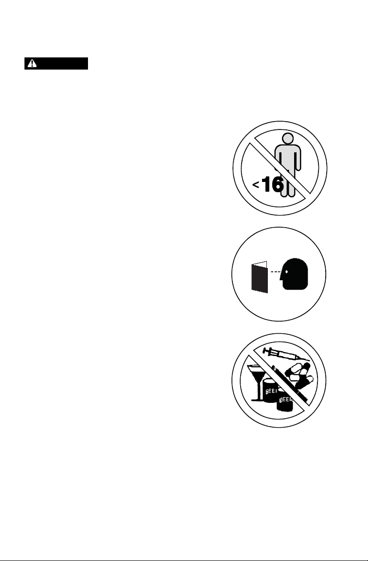
Age Restrictions
This vehicle is an ADULT VEHICLE ONLY.
NEVER operate this vehicle if you are under
age 16 and NEVER operate without a valid
driver’s license.
No person under the age of 12 may ride as
a passenger in this vehicle. Any passenger
must be able to comfortably reach the floor
and hand holds.
Operating Without Instruction
Operating this vehicle without proper
instruction increases the risk of an accident.
The operator must understand how to
operate the vehicle properly in different
situations and on different types of terrain.
All operators must read and understand the
Owner's Manual and all warning and
instruction labels before operating the
vehicle.
Using Alcohol or Drugs
Operating the vehicle after consuming alcohol
or drugs could adversely affect operator
judgment, reaction time, balance and
perception.
Never drink alcohol or use drugs or medications
before or while operating this vehicle.
16
Page 21

SAFETY
Operator Safety
Seat Belts
Riding in this vehicle without wearing the seat belt increases the risk of serious
injury in the event of an accident or sudden stop. Riders must wear seat belts at
all times. Seat belts reduce the severity of injury in the event of a sudden stop or
accident. Always make sure the seat belts are secured for both the operator and
passenger before riding.
Failure to Inspect Before Operating
Failure to inspect and verify that the vehicle is in safe operating condition before
operating increases the risk of an accident.
Always inspect your RANGER before each use to make sure it's in safe
operating condition.
Always follow all inspection and maintenance procedures and schedules
described in the owner's manual.
Handling Gasoline
Gasoline is highly flammable and explosive under certain conditions.
• Always exercise extreme caution whenever handling gasoline.
• Always stop the engine when refueling.
• Always refuel outdoors or in a well ventilated area.
• Remove flammable material containers from the box before filling them with
fuel.
• Do not smoke or allow open flames or sparks in or near the area where refu-
eling is performed or where gasoline is stored.
• Do not overfill the tank. Do not fill the tank neck.
• If gasoline spills on your skin or clothing, immediately wash it off with soap
and water and change clothing.
17
Page 22

SAFETY
Operator Safety
Exposure to Exhaust
Engine exhaust fumes are poisonous and can cause loss of consciousness or
death in a short time. Never start the engine or let it run in an enclosed area.
The engine exhaust from this product contains chemicals known to cause
cancer, birth defects or other reproductive harm. Operate this vehicle only
outdoors or in well-ventilated areas.
Operating a Damaged Vehicle
Operating a damaged vehicle can result in an accident. After any overturn or
accident, have a qualified service dealer inspect the entire machine for possible
damage, including (but not limited to) brakes, throttle and steering systems.
Operating at Excessive Speeds
Operating this vehicle at excessive speeds increases the operator's risk of
losing control. Always operate at a speed that's appropriate for the terrain, the
visibility and operating conditions, your skills and your passenger’s skills.
Operating on Pavement
This vehicle's tires are designed for off-road use only, not for use on pavement.
Operating this vehicle on paved surfaces (including sidewalks, paths, parking
lots and driveways) may adversely affect the handling of the vehicle and could
result in loss of control and accident or overturn.
Avoid operating the vehicle on pavement. If it's unavoidable, travel slowly and
avoid sudden turns or stops.
18
Page 23

SAFETY
Operator Safety
Operating on Public Roads
Operating this vehicle on public streets, roads or highways could result in a
collision with another vehicle.
Never operate this vehicle on any public street, road or highway, including dirt
and gravel roads. In some areas it's unlawful to operate this vehicle on public
streets, roads and highways.
Turning Improperly
Turning improperly could cause loss of traction, loss of control, accident or
overturn. Always follow proper procedures for turning. Never turn abruptly or at
sharp angles. Never turn at high speeds. Practice turning at slow speeds before
attempting to turn at faster speeds.
Jumps and Stunts
Attempting wheelies, jumps and other stunts increases the risk of an accident or
overturn. Never attempt wheelies, jumps, or other stunts. Avoid exhibition
driving.
Operating in Unfamiliar Terrain
Failure to use extra caution when operating on unfamiliar terrain could result in
an accident or overturn. Unfamiliar terrain may contain hidden rocks, bumps, or
holes that could cause loss of control or overturn.
Travel slowly and use extra caution when operating on unfamiliar terrain. Always
be alert to changing terrain conditions.
19
Page 24

SAFETY
Operator Safety
Operating on Slippery Terrain
Failure to use extra caution when operating on excessively rough, slippery or
loose terrain could cause loss of traction, loss of control, accident or overturn.
Do not operate on excessively slippery surfaces.
Always reduce speed and use additional caution when operating on slippery
surfaces.
Improper Hill Climbing
Climbing hills improperly can cause loss of control or vehicle overturn. Always
follow proper procedures for climbing hills as described in the owner's manual.
See page 48.
Stalling While Climbing a Hill
Stalling or rolling backwards while climbing a hill could cause an overturn.
Always maintain a steady speed when climbing a hill.
If all forward speed is lost:
• Apply the brakes.
• Place the transmission in reverse and slowly allow the vehicle to roll straight
downhill while applying light brake pressure to control speed.
If you begin rolling downhill:
• Never apply engine power.
• Apply the brakes gradually until the vehicle is fully stopped.
• Place the transmission in reverse and slowly allow the vehicle to roll straight
downhill while applying light brake pressure to control speed.
20
Page 25

SAFETY
Operator Safety
Improper Tire Maintenance
Operating this vehicle with improper tires or with improper or uneven tire
pressure could cause loss of control or accident.
Always use the size and type of tires specified for your vehicle.
Always maintain proper tire pressure as described in the owner's manual and on
safety labels.
Operating on Frozen Bodies of Water
Severe injury or death can result if the vehicle and/or the operator fall through
the ice. Never operate the vehicle on a frozen body of water.
Unauthorized Use of the Vehicle
Leaving the keys in the ignition can lead to unauthorized use of the vehicle,
which could result in an accident or overturn. Always remove the ignition key
when the vehicle is not in use.
Hot Exhaust Systems
Exhaust system components are very hot during and after use of the vehicle.
Hot components can cause burns and fire. Do not touch hot exhaust system
components. Always keep combustible materials away from the exhaust
system. Use caution when traveling through tall grass, especially dry grass.
21
Page 26
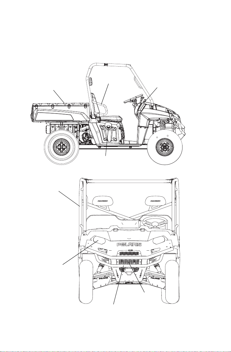
FEATURES AND CONTROLS
Headlights
Front Bumper/Brush Guard
Radiator
ROPS Cab
Frame
Console
Hip Bar
Cargo Box
Fuel Tank Cap
Component Locations
Not all models come with all features. Refer to the specifications section
beginning on page 110.
22
Page 27
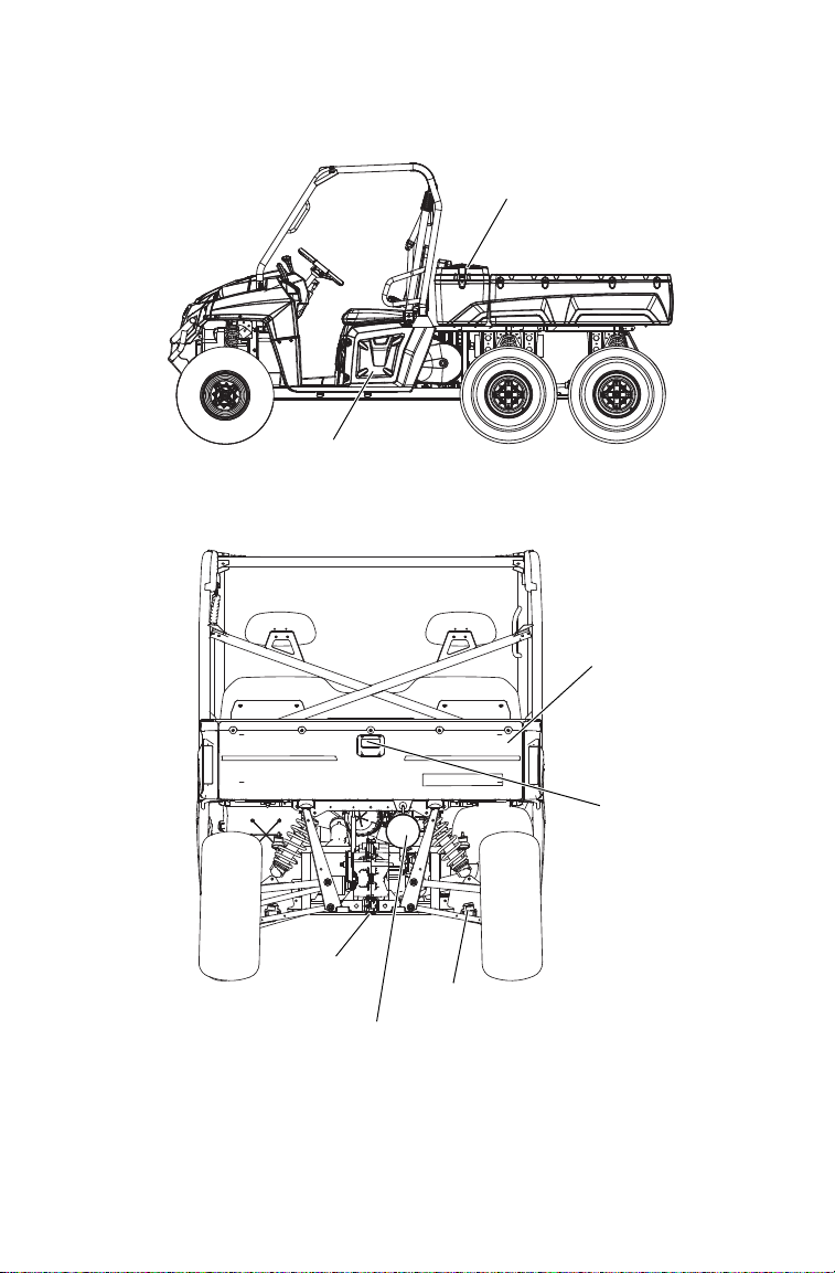
FEATURES AND CONTROLS
Tailgate
Latch Release
Receiver
Hitch
CV Boot/Rear Caliper
Muffler (Spark Arrestor)
Tailgate
6X6 Storage Box
Storage
Compartment
Component Locations
23
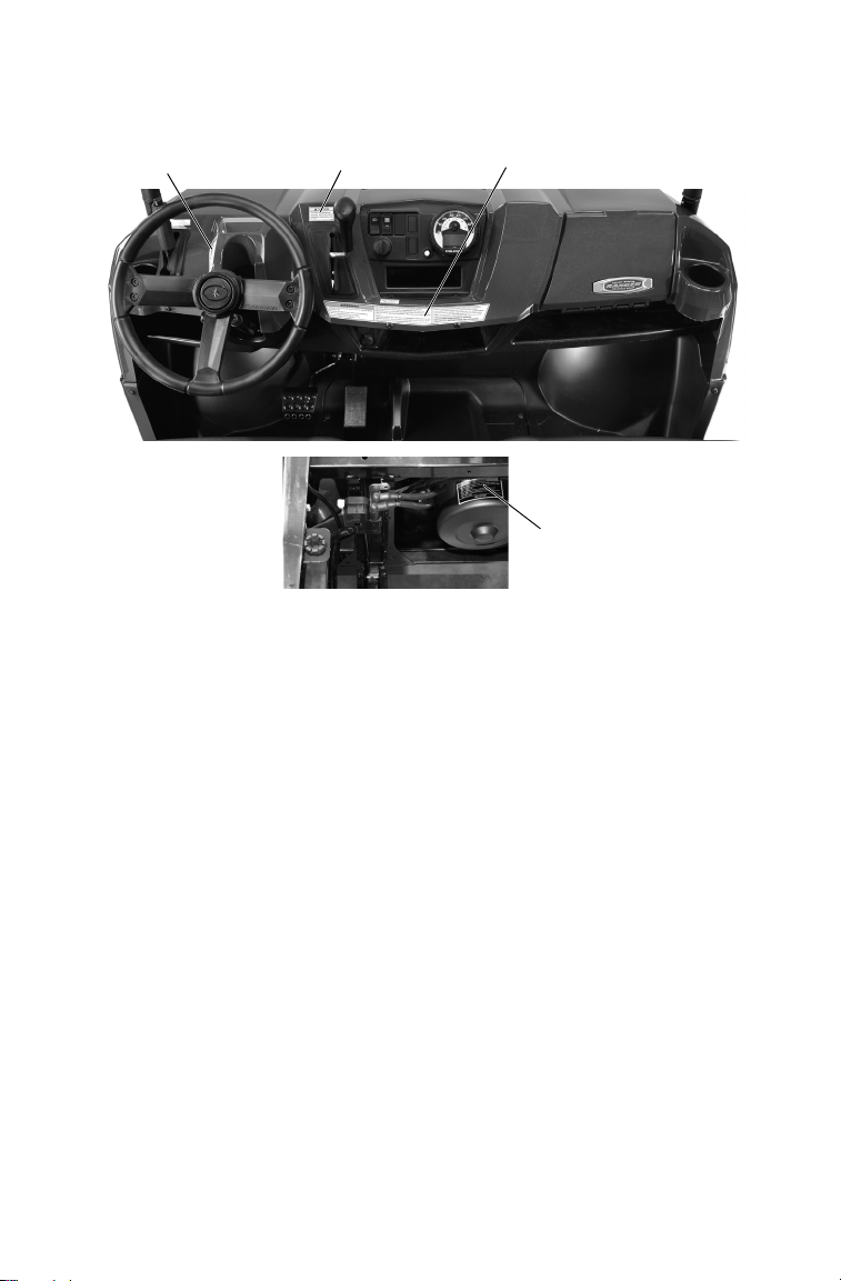
Page 28
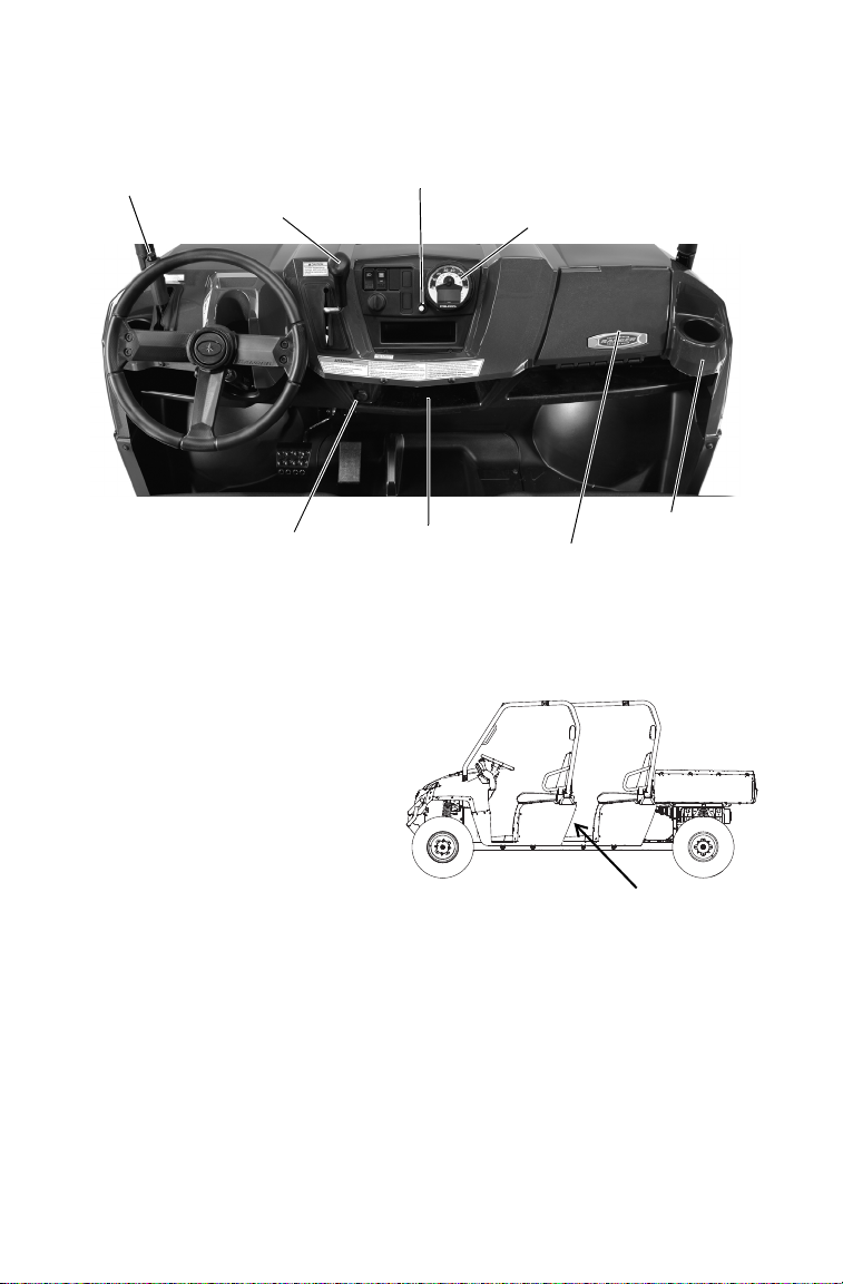
FEATURES AND CONTROLS
Cup Holder
12V Auxiliary
Outlets
Mode
Button
Storage
Tray
Instrument
Cluster
Gear Selector
(Shifter)
Park Brake
Lever
Storage
Compartment
12V Accessory
Outlet
Console
Auxiliary Outlets
The 12-volt receptacles have
spade connections on the back
that may be used to power an
auxiliary light or other optional
accessories or lights. The connections are behind the console,
under the dash.
On Crew models, an additional
receptacle is located on the rear
of the driver’s seat.
24
Page 29

FEATURES AND CONTROLS
Console
Mode Button
The yellow button located directly under the speedometer is used to toggle through mode options available such as odometer, trip meter, hour
meter and tachometer. See page 35 for operation of the modes.
Gear Selector
H: High Gear
L: Low Gear
N: Neutral
R: Reverse
Low gear is the primary driving range for the RANGER. High gear is
intended for use on hard-packed surfaces with light loads.
To shift gears, brake to a complete stop. When the engine is idling,
move the lever to the desired gear.
NOTICE: Shifting gears with the engine speed above idle or while the vehicle is
Tip: Maintaining shift linkage adjustment is important to assure proper transmis-
moving could cause transmission damage. Always shift when the
vehicle is stationary and the engine is at idle.
sion function. See your dealer if you experience any shifting problems.
25
Page 30
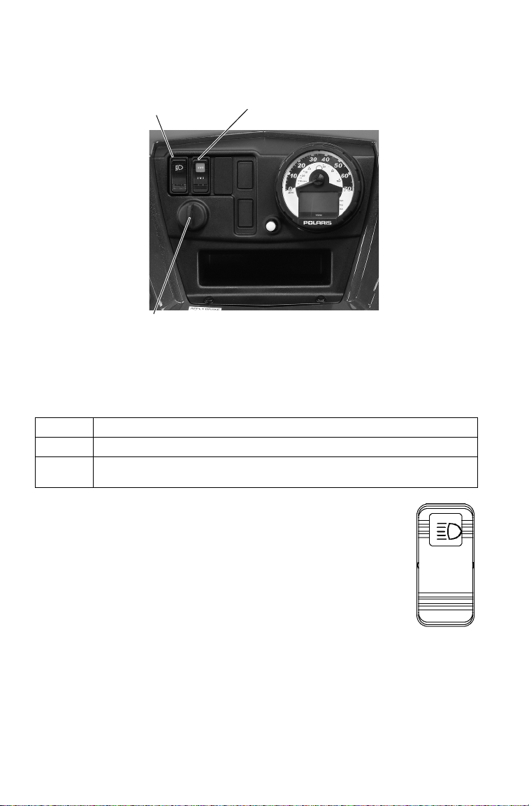
FEATURES AND CONTROLS
Ignition Switch
Light
Switch
AWD/Differential Switch
ON
OFF
Switches
Ignition Switch
The ignition switch is a three-position, key-operated switch. The key
can be removed from the switch when it is in the OFF position.
OFF The engine is off. Electrical circuits are off, except Acc, 12V.
ON Electrical circuits are on. Electrical equipment can be used.
START Turn the key to the START position to engage the electric starter.
The key returns to the ON position when released.
Light Switch
The ignition switch key must be in the ON/RUN
position to operate the headlights. Use the light
switch to turn the headlights on or off.
26
Page 31

FEATURES AND CONTROLS
AWD
Differential Lock
Differential Unlock
Switches
AWD/Differential Lock Switch
The AWD/Differential Switch has
three positions:
• All Wheel Drive (AWD)
• Differential Lock (2WD)
• Differential Unlock
Press the top of the rocker switch to
engage All Wheel Drive (AWD). See
page 59 for operating instructions.
Move the rocker switch to the center
position to lock the differential and
operate in rear wheel drive. Press the
bottom of the switch to unlock the differential and allow the two rear drive
wheels to operate independently. See
page 60 for differential lock operating
instructions.
27
Page 32

FEATURES AND CONTROLS
Throttle
Pedal
Brake
Pedal
Trailer Hitch Bracket
This vehicle is equipped with a receiver hitch bracket for a trailer hitch.
To avoid injury and property damage, always heed the warnings and
towing capacities outlined on pages 54-56.
Brake Pedal
Depress the brake pedal to slow or
stop the vehicle. Apply the brakes
while starting the engine.
Throttle Pedal
Push the throttle pedal down to
increase engine speed. Spring pressure returns the pedal to the rest position when released. Always check
that the throttle pedal returns normally before starting the engine.
Make sure there's adequate throttle
pedal freeplay. See page 89 for throttle pedal adjustment procedures.
Adjustable Steering Wheel
The steering wheel can be tilted
upward or downward for rider
preference.
Lift and hold the adjustment lever
toward you while moving the steering wheel upward or downward.
Release the lever when the steering
wheel is at the desired position.
28
Page 33

FEATURES AND CONTROLS
Park Brake Lever
To help prevent the vehicle from rolling, engage the park brake when
parking the vehicle. When the park brake is fully engaged and the park
brake indicator is illuminated, engine speed is limited to 1300 RPM in
all gears, except neutral. If throttle is applied, this limiting feature prevents operation, which protects the park brake pads from excessive
wear.
Tip: This feature will not operate properly if the park brake connector or switch
(under the hood) malfunctions or becomes disconnected, or if the switch
has moved. Check for disconnection, then see your dealer promptly if this
feature fails to operate properly.
Inspect and adjust park brake cable tension after the first 25 hours of
operation and every 100 hours thereafter to ensure proper cable tension.
See page 92.
Always apply the service brakes
before engaging or releasing the
park brake.
1. Apply the brakes.
2. Pull the park brake lever
downward as far as possible.
3. To release the park brake,
apply the brakes. Press the
park brake release inward and
move the lever upward as far
as possible.
WARNING! Operating the vehicle while the park brake is engaged could cause
loss of control and result in serious injury or death. Always disengage the park
brake before operating the vehicle.
29
Page 34

FEATURES AND CONTROLS
Buckle
Latch Plate
Seat Belts
This Polaris vehicle is equipped with
three-point lap and diagonal seat belts on
all external seats.The center seat is
equipped with a lap-style seat belt. Always
make sure the seat belts are secured for all
riders before operating.
WARNING! Falling from a moving vehicle
could result in serious injury or death. Always
fasten your seat belt securely before operating
or riding in the RANGER.
To wear the seat belt properly, follow this
procedure:
1. For 3-point belts, pull the seat belt
latch downward and across your chest
toward the buckle at the inner edge of
the seat. The belt should fit snugly
across your hips and diagonally across
your chest. Make sure the belt is not
twisted. For lap style belts, place the
belt across your lap as low on your
hips as possible. Make sure that the
belt is not twisted.
2. Push the latch plate into the buckle until it clicks.
3. Release the strap, it will self-tighten.
Tip: The center belt must be tightened manually by pulling on the strap.
4. To release the seat belt, press the square red button in the buckle's
center.
30
Page 35

FEATURES AND CONTROLS
Seat Belts
Seat Belt Inspection
Inspect all seat belts for proper operation before each use of the vehicle.
1. Push the latch plate into the buckle until it clicks. The latch plate
must slide smoothly into the buckle. A click indicates that it's
securely latched.
2. Push the red release latch in the middle of the buckle to make sure it
releases freely.
3. Pull each seat belt completely out and inspect the full length for any
damage, including cuts, wear, fraying or stiffness. If any damage is
found, or if the seat belt does not operate properly, have the seat belt
system checked and/or replaced by an authorized Polaris dealer.
4. To clean dirt or debris from the seat belts, sponge the straps with
mild soap and water. Do not use bleach, dye or household detergents.
Seat Removal
Pull up on the front of the seat and slide it toward the front of the vehicle. Install the seat by sliding the tabs into the rear of the seat base. Push
down firmly on the front of the seat until the pins are fully seated into
the grommets.
Fuel Cap
The fuel tank filler cap is located on
the right-hand side of the vehicle
near the passenger seat. When refueling, always use either leaded or
unleaded gasoline with a minimum
pump octane number of 87 R+M/2
octane. Do not use fuel with ethanol
content greater than 10 percent,
such as E-85 fuel.
31
Page 36

FEATURES AND CONTROLS
6X6 Storage
Box
ROPS
(all models)
Large Storage
Compartment
(Crew only)
Small Storage
Compartment
(left side only)
Rollover Protective Structure (ROPS)
The Rollover Protective Structure (ROPS) on this vehicle meets OSHA
1928.53 rollover performance requirements. Always have your autho-
rized Polaris dealer thoroughly inspect the ROPS if it ever becomes
damaged in any way.
No device can assure occupant protection in the event of a rollover.
Always follow all safe operating practices outlined in this manual to
avoid vehicle rollover.
WARNING! Vehicle rollover could cause severe injury or death. Always avoid
operating in a manner that could result in vehicle rollover.
Storage Compartments
A storage compartment is located under the driver’s seat, and on Crew
models, under the left rear seat. On 6X6 models, a lockable storage box
is located behind the ROPS. Always make sure the cover is securely
latched before operating. The box is accessible from both sides of the
vehicle.
32
Page 37

FEATURES AND CONTROLS
Rider
Information
Center
Speedometer
Speedometer
Needle
Park Brake
Indicator
Instrument Cluster
The instrument cluster measures distance traveled by the vehicle, as
well as time, hours of operation and engine RPM.
Tip: In addition to showing vehicle speed, the speedometer needle flashes when
a low fuel condition exists.
33
Page 38

FEATURES AND CONTROLS
1
2
345
6
7
8
Instrument Cluster
Rider Information Center
The rider information center is located in the instrument cluster. All segments will light up for 2.5 seconds at start-up.
Tip: If the instrument cluster fails to illuminate, a battery over-voltage may have
occurred and the instrument cluster may have shut off to protect the electronic speedometer. If this occurs, take the vehicle to your Polaris dealer for
proper diagnosis.
1. Gear Indicator - This
indicator displays gear
shifter position.
H = High Gear
L = Low Gear
N = Neutral
R = Reverse Gear)
2. AWD Indicator - This
indicator illuminates
when the AWD switch
is in the AWD position.
3. Engine Hour Display Indicator
4. Service Interval/Diagnostic Mode Indicator
5. Low Battery and Over Voltage - This warning usually indicates
that the vehicle is operating at an RPM too low to keep the battery
charged. It may also occur when the engine is at idle and high electrical load (lights, cooling fan, accessories) is applied. Drive at a
higher RPM or recharge the battery to clear the warning.
6. Odometer/Tachometer/Tripmeter/ Hour Meter
7. Fuel Gauge - The segments of the fuel gauge show the level of fuel
in the fuel tank. When the last segment clears, a low fuel warning is
activated. All segments will flash, FUEL will display in the LCD,
and the speedometer needle will blink. Refuel immediately.
8. Check Engine Warning Indicator - This indicator serves two pur-
poses. The word HOT displays if the engine overheats. It also
appears if an EFI-related fault occurs. Do not operate the vehicle if
this warning appears. Serious engine damage could result.
34
Page 39

FEATURES AND CONTROLS
Instrument Cluster
Rider Information Center
Standard Modes
Use the yellow mode button located under the speedometer to toggle
through the mode options. See page 24.
Odometer Mode
The odometer records the miles traveled by the vehicle.
Trip Meter Mode
The trip meter records the miles traveled by the vehicle on each trip if
it's reset before each trip. To reset the trip meter, select the trip meter
mode. Press and hold the mode button until the total changes to 0.
Tip: In the Rider Information Center, the trip meter display contains a decimal
point, but the odometer displays without a decimal point.
Hour Meter Mode
This mode logs the total hours the engine has been in operation.
Tachometer Mode
The engine RPM is displayed digitally. Small fluctuations in the RPM
from day to day may be normal because of changes in humidity, temperature and elevation.
35
Page 40

FEATURES AND CONTROLS
Instrument Cluster
Rider Information Center
Diagnostic Mode
The wrench icon will display when the gauge is in the diagnostic mode.
To exit the diagnostic mode, turn the key switch off and on. Any movement of the tires will also cause the gauge to exit the diagnostic mode.
To enter the diagnostics mode:
1. Turn the key switch off and wait 10 seconds.
2. Lock the parking brake.
3. Place the transmission in neutral.
4. Hold the mode button and turn the key switch on. Release the
switch as soon as the display is activated.
5. Use the mode button to toggle through the diagnostic screens.
36
Page 41

FEATURES AND CONTROLS
Instrument Cluster
Rider Information Center
Diagnostic Mode
Battery Voltage Screen
View this screen to check battery voltage level.
Tachometer Screen
View the tachometer to check engine speed.
AWD Diagnostic Screen
The gauge indicates whether or not current is flowing through the AWD
coil (only on models with switchable AWD). This screen is for informational purposes only. Please see your dealer for all major repairs.
Gear Circuit Diagnostic Screen
This screen displays the resistance value (in ohms) being read at the
gear switch input of the gauge. This screen is for informational purposes
only. Please see your dealer for all major repairs.
Programmable service interval
When the hours of engine operation equal the programmed service
interval setting, the wrench icon will flash for 5 seconds each time the
engine is started. When this feature is enabled, it provides a convenient
reminder to perform routine maintenance. See page 38.
The service interval is programmed at 50 hours at the factory.
37
Page 42

FEATURES AND CONTROLS
Instrument Cluster
Rider Information Center
Diagnostic Mode
Programmable service interval
To enable or disable the service interval:
1. Enter the diagnostic mode.
2. Toggle to the service interval screen.
3. Press and hold the mode button for about seven (7) seconds, until
either ON or OFF appears in the Rider Information Center, depending on your preference.
To reset the service interval:
1. Enter the diagnostic mode.
2. Toggle to the service interval screen.
3. Press and hold the mode button for 2-3 seconds, until the wrench
icon flashes. Release the button.
4. Press and release the mode button once to advance the setting by
one hour. Press and hold the mode button to advance the hours
quickly. If you scroll past the intended number, press and hold the
button until the hours cycle back to zero.
5. When the desired setting is displayed, wait until the wrench icon
stops flashing. The new service interval is now programmed.
Miles/Kilometers toggle
The display in the tripmeter and odometer can be changed to display
either standard or metric units of measurement.
1. Enter the diagnostic mode.
2. Toggle to the screen that displays either kilometers (KM) or miles
(MP).
3. Press and hold the mode button until the letters flash, then press and
release the button once. When the display stops flashing, the mode
has been set.
38
Page 43

FEATURES AND CONTROLS
Instrument Cluster
Rider Information Center
Accessing Blink Codes
The EFI diagnostic mode is for informational purposes only. Please see
your Polaris dealer for all major repairs.
See page 40 for Blink Codes and Failure Descriptions. Use the following procedure to access blink codes (failure codes) from the EFI module.
1. Apply the brakes.
2. Engage the park brake.
3. Stop the engine.
4. Turn the key switch to the ON position.
5. Turn the key switch off and on three times in less than five seconds,
then leave the switch on. Any blink code numbers stored in the EFI
module will display, one at a time, on the screen. The number “61”
and the word “END” displays after all codes have been transmitted.
39
Page 44

FEATURES AND CONTROLS
Instrument Cluster
Rider Information Center
Blink Code Descriptions
Blink
Code
-- No RPM Signal
21 Loss of Synchronization
45 Barometric Pressure Sensor: Circuit Low Input
46 Barometric Pressure Sensor: Circuit High Input
22 TPS: Open or Short Circuit to Ground
22 TPS: Short Circuit to Battery
23 RAM Error: Defective ECU
42 Engine Temp Sensor Circuit: Short to Ground
42 Engine Temp Sensor Circuit: Open or Short to Battery
51 Injector 1: Open Load
51 Injector 1: Short Circuit to Ground
51 Injector 1: Short Circuit to Battery
52 Injector 2: Open Load
52 Injector 2: Short Circuit to Ground
52 Injector 2: Short Circuit to Battery
53 Rear Differential: Open Load (RANGER 4X4 only)
53 Rear Differential: Short Circuit to Ground (RANGER 4X4 only)
53 Rear Differential: Short Circuit to Battery (RANGER 4X4 only)
54 Engine Temp Lamp: Open Load
54 Engine Temp Lamp: Short Circuit to Ground
54 Engine Temp Lamp: Short Circuit to Battery
55 Diag Lamp: Open Load
55 Diag Lamp: Short Circuit to Ground
55 Diag Lamp: Short Circuit to Battery
56 Pump Relay: Open Load
56 Pump Relay: Short Circuit to Ground
56 Pump Relay: Short Circuit to Battery
57 Reverse Beeper: Open Load
57 Reverse Beeper: Short Circuit to Ground
57 Reverse Beeper: Short Circuit to Battery
58 Cooling Fan: Open Load
58 Cooling Fan: Short Circuit to Ground
58 Cooling Fan: Short Circuit to Battery
41 Intake Air Temp Sensor: Open or Short Circuit to +Sensor Voltage
41 Intake Air Temp Sensor: Short Circuit to Ground
61 END
Failure Description
40
Page 45

OPERATION
WARNING
Failure to operate the vehicle properly can result in a collision, loss of control,
accident or overturn, which may result in serious injury or death. Read and
understand all safety warnings outlined in the safety section of this owner’s
manual.
Break-In Period
The break-in period for your new Polaris RANGER is the first twenty
hours of operation, or the time it takes to use the first two tanks full of
gasoline. No single action on your part is as important as a proper breakin period. Careful treatment of a new engine will result in more efficient
performance and longer life for the engine. Perform the following procedures carefully.
NOTICE: Excessive heat build-up during the first three hours of operation will
damage close-fitted engine parts. Do not operate at full throttle or
high speeds for extended periods during the first three hours of use.
41
Page 46

OPERATION
Break-In Period
Engine and Drivetrain Break-in
1. Fill the fuel tank with gasoline. Review the gasoline warnings on
page 17.
2. Check the oil level. Add the recommended oil as needed to maintain
the oil level in the normal (safe) operating range.
3. Drive slowly at first. Select an open area that allows room to familiarize yourself with vehicle operation and handling.
4. Vary throttle positions. Do not operate at sustained idle.
5. Perform regular checks on fluid levels, controls and areas outlined
on the daily pre-ride inspection checklist. See page 43.
6. Pull only light loads.
7. During the break-in period, change both the oil and the filter at 25
hours.
8. Inspect and adjust park brake cable tension after the first 25 hours of
operation and every 100 hours thereafter to ensure proper cable tension. See page 92.
PVT Break-in (Clutches/Belt)
A proper break-in of the clutches and drive belt will ensure a longer life
and better performance. Break in the clutches and belt by operating at
slower speeds during the break-in period as recommended. Pull only
light loads. Avoid aggressive acceleration and high speed operation during the break-in period.
42
Page 47

OPERATION
Pre-Ride Inspection
Failure to inspect and verify that the vehicle is in safe operating condition before operating increases the risk of an accident. Always inspect
the vehicle before each use to make sure it's in safe operating condition.
Item Remarks Page
Brake system/pedal travel Ensure proper operation 28
Brake fluid Ensure proper level 90
Front suspension Inspect, lubricate if necessary 67
Rear suspension Inspect, lubricate if necessary 67
Steering Ensure free operation 92
Tires Inspect condition and pressure 94
Wheels/fasteners Inspect, ensure fastener tightness 94
Frame nuts, bolts, fasteners Inspect, ensure tightness -
Fuel and oil Ensure proper levels 34
Coolant level Ensure proper level 80
Coolant hoses Inspect for leaks -
Throttle Ensure proper operation 88
Indicator lights/switches Ensure operation 26
Air filter, pre-filter Inspect, clean 85
Air box sediment tube Drain deposits whenever visible 85
Headlamp Check operation, apply Polaris dielec-
Brake light/tail lamp Check operation, apply Polaris dielec-
Seat Belts Check length of belt for damage,
tric grease when lamp is replaced
tric grease when lamp is replaced
check latches for proper operation
90
69
81
96
96
31
43
Page 48

OPERATION
Starting the Engine
1. Always start the engine outdoors or in a well-ventilated area.
2. Sit in the driver's seat and fasten the seat belt.
3. Apply the brakes. Engage the park brake.
4. Shift the transmission to neutral.
5. Do not press the throttle pedal while starting the engine. Turn the
ignition key past the ON/RUN position to START. Engage the
starter for a maximum of five seconds. Release the key when the
engine starts.
6. If the engine does not start within five seconds, release the ignition
switch and wait five seconds. Repeat steps 5 and 6 until the engine
starts.
7. Vary the engine RPM slightly with the throttle to aid in warm up
until the engine idles smoothly.
NOTICE: Operating the vehicle immediately after starting could cause engine
damage. Allow the engine to warm up for several minutes before
operating the vehicle.
44
Page 49

OPERATION
Stopping the Engine
1. Release the throttle pedal completely and brake to a complete stop.
2. Turn the engine off.
3. Engage the park brake.
WARNING! A rolling vehicle can cause serious injury. Always engage the park
brake after stopping the engine.
Braking
1. Release the throttle pedal completely.
2. Press on the brake pedal evenly and firmly.
3. Practice starting and stopping (using the brakes) until you're familiar with the controls.
Tip: When the throttle pedal is released completely and the engine speed drops
near an idle, the vehicle has no engine braking.
45
Page 50

OPERATION
Driving Procedure
1. Wear a helmet and eye protection.
2. Perform the pre-ride inspection. See page 43.
3. Sit in the driver's seat and fasten the seat belt.
4. Start the engine and allow it to warm up.
5. Apply the service brakes and shift the transmission into gear.
6. Check your surroundings and determine your path of travel.
7. Release the park brake.
8. Keeping both hands on the steering wheel, slowly release the brakes
and depress the throttle with your right foot to begin driving.
9. Drive slowly. Practice maneuvering and using the throttle and
brakes on level surfaces.
10. Do not carry a passenger until you have at least two hours of driving
experience with this vehicle.
46
Page 51

OPERATION
WARNING
Sideways
skid
Turn in
direction of
skid
Driving on Slippery Surfaces
Skidding or sliding can cause loss of control or overturn (if tires regain traction
unexpectedly). When operating on slippery surfaces such as ice or loose gravel,
reduce speed and use extra caution to reduce the chance of skidding or sliding
out of control. Do not operate on excessively slippery surfaces.
Whenever riding on slippery surfaces such as wet trails or loose gravel,
or during freezing weather, follow these precautions:
1. Do not operate on excessively rough, slippery or loose terrain.
2. Slow down before entering slippery areas.
3. Maintain a high level of alertness, reading the trail and avoiding
quick, sharp turns, which can cause skids.
4. Engage all-wheel drive before wheels begin to lose traction.
NOTICE: Severe damage to the drive train may occur if the AWD is engaged
5. Correct a skid by turning the steering wheel in the direction of the
while the wheels are spinning. Always allow the wheels to stop
spinning before engaging AWD.
skid. Never apply the brakes during a skid.
47
Page 52

OPERATION
15° maximum
Driving Uphill
Whenever traveling
uphill, follow these precautions:
1. Always travel
straight uphill.
2. Avoid steep hills
(15° maximum).
3. Keep both feet on
the floor.
4. Always check the
terrain carefully
before ascending
any hill.
5. Never climb hills with excessively slippery or loose surfaces.
6. Proceed at a steady rate of speed and throttle opening. Never open
the throttle suddenly.
7. Never go over the crest of a hill at high speed. An obstacle, a sharp
drop, or another vehicle or person could be on the other side of the
hill.
48
Page 53

OPERATION
15° maximum
Driving on a Sidehill (Sidehilling)
Driving on a sidehill is not recommended. Improper procedure could
cause loss of control or overturn. Avoid crossing the side of any hill
unless absolutely necessary.
If crossing a sidehill is unavoidable, follow these precautions:
1. Slow down.
2. Exercise extreme caution.
3. Avoid crossing the side of a steep hill (15° maximum).
Driving Downhill
When driving downhill,
follow these precautions:
1. Avoid steep hills (15°
maximum).
2. Drive straight downhill. Avoid descending
a hill at an angle,
which would cause the
vehicle to lean sharply
to one side. Travel
straight downhill when
possible.
3. Slow down.
4. Apply the brakes slightly to aid in slowing.
49
Page 54

OPERATION
Floorboard
Driving Through Water
You r P ol a r i s RANGER can operate through water up to a maximum recommended depth equal to the floorboards.
NOTICE: Immersion can result in major damage if the vehicle isn't serviced
Follow these procedures
when operating through
water:
1. Determine water
2. Choose a crossing
3. Proceed slowly,
4. Avoid operating
WARNING! The large tires on your RANGER may cause the vehicle to float in
deep or fast-flowing water, which could result in loss of control and lead to
serious injury or death. Never cross deep or fast-flowing water with your
RANGER.
5. After leaving water, always dry the brakes by applying light pres-
NOTICE: After running your vehicle in water, it's critical that you perform the
correctly and promptly. After immersion, always take the vehicle to
your dealer service. Do not start the engine! If it's impossible to bring
the vehicle to your dealer before starting the engine, perform the
service outlined on page 84, and take the vehicle to your dealer at
the first opportunity.
depths and current
before entering water.
where both banks
have gradual inclines.
avoiding rocks and
obstacles.
through deep or fastflowing water.
sure to the pedal repeatedly until braking action is normal.
services outlined in the Periodic Maintenance Chart beginning on
page 62. Give special attention to engine oil, transmission oil, all
gearcase fluids, and all grease fittings.
50
Page 55

OPERATION
Driving Over Obstacles
Follow these precautions when operating over obstacles:
1. Always check for obstacles before operating in a new area.
2. Look ahead and learn to read the terrain. Be constantly alert for hazards such as logs, rocks and low hanging branches.
3. Travel slowly and use extra caution when operating on unfamiliar
terrain. Not all obstacles are immediately visible.
51
Page 56

OPERATION
Driving in Reverse
Follow these precautions when operating in reverse:
1. Always check for obstacles or people behind the vehicle. Always
inspect left and right fields of vision before backing.
2. Always avoid backing downhill.
3. Back slowly.
4. Apply the brakes lightly for stopping.
5. Avoid turning at sharp angles.
6. Never open the throttle suddenly.
52
Page 57

OPERATION
15° maximum
Parking on an Incline
Avoid parking on an incline if possible. If it's unavoidable, follow these
precautions:
1. Apply the brakes.
2. Place the transmission in gear.
3. Engage the park brake.
4. Turn the engine off.
5. Block the rear wheels on the downhill side.
53
Page 58

OPERATION
WARNING
Hauling Cargo
Hauling cargo improperly can alter vehicle handling and may cause loss of
control or brake instability, which can result in serious injury or death. Always
follow these precautions when hauling cargo:
Never exceed the maximum weight capacity of the vehicle. When determining
the weight you are adding to the vehicle, include the weight of the operator,
passenger, accessories, loads in the rack or box and the load on the trailer
tongue. The combined weight of these items must not exceed the maximum
weight capacity.
REDUCE SPEED AND ALLOW GREATER DISTANCES FOR BRAKING
WHEN HAULING CARGO.
Always load the cargo box with the load as far forward and as low as possible.
When operating over rough or hilly terrain, reduce speed and cargo to maintain
stable driving conditions.
Always operate the vehicle with extreme care when hauling or towing loads.
Slow down and drive in the lowest gear available.
SECURE ALL LOADS BEFORE OPERATING. Unsecured loads can create
unstable operating conditions, which could result in loss of control of the vehicle.
OPERATE ONLY WITH STABLE AND SAFELY ARRANGED LOADS. When
handling off-centered loads that cannot be centered, securely fasten the load
and operate with extra caution. Always attach the tow load to the hitch point
designated for your vehicle.
HEAVY LOADS CAN CAUSE BRAKING AND CONTROL PROBLEMS. Use
extreme caution when applying brakes with a loaded vehicle. Avoid terrain or
situations that may require backing downhill.
USE EXTREME CAUTION when operating with loads that extend over the rack
sides. Stability and maneuverability may be adversely affected, causing the
vehicle to overturn.
DO NOT TRAVEL FASTER THAN THE RECOMMENDED SPEEDS. Vehicle
should never exceed 10 mph (16 kph) while towing a load on a level grass
surface. Vehicle speed should never exceed 5 mph (8 kph) when towing loads in
rough terrain, while cornering, or while ascending or descending a hill.
54
Page 59

OPERATION
Hauling Cargo
The RANGER has been designed to carry or tow specific capacities.
Always read and understand the load distribution warnings listed on the
warning labels. The total load (operator, passenger, accessories, cargo
and weight on hitch) must not exceed the maximum weight capacity of
the vehicle. Never exceed the following capacities.
Model Maximum Total
RANGER 4X4 1500 lbs. (681 kg) 1000 lbs. (454 kg)
RANGER 6X6 2000 lbs. (907 kg) 1250 lbs. (567 kg) Cargo Box
RANGER CREW 1750 lbs. (794 kg) 1000 lbs. (454 kg)
WARNING! Driving with
passengers in the cargo box
can result in severe injury or
death. Never allow passengers
to ride in the cargo box.
Passengers must always ride
in the cab with seat belts
fastened securely.
Weight Capacity
(Level Ground)
Maximum Cargo Box
Weight Capacity
250 lbs. (113 kg) Storage Box
55
Page 60

OPERATION
Towing Loads
Towing improperly can alter vehicle handling and may cause loss of
control or brake instability. Always follow these precautions when towing:
1. Never load more than 150 lbs. (68.1 kg) tongue weight on the towing bracket.
2. Do not operate the vehicle faster than 10 mph (16 km/h) when towing. See page 54. Towing a trailer increases braking distance.
3. Do not tow more than the recommended weight for the vehicle. See
the towing capacity chart below and the specifications charts beginning on page 110.
4. Attach a trailer to the trailer hitch bracket only. Do not attach a
trailer to any other location or you may lose control of the vehicle.
5. Never tow a trailer on a grade steeper than 15°.
Model Total Towed
RANGER 4x4 2000 lbs.
RANGER 6x6 2000 lbs.
RANGER CREW 2000 lbs.
Load Weight
(Level Ground)
(907 kg)
(907 kg)
(907 kg)
Total Towed
Load Weight
(15° grade)
850 lbs.
(386 kg)
850 lbs.
(386 kg)
850 lbs.
(386 kg)
Tota l H i t c h
Vertical
Weight
150 lbs.
(68.1 kg)
150 lbs.
(68.1 kg)
150 lbs.
(68.1 kg)
Maximum
Tow i n g
Speed
10 mph
(16 kph)
10 mph
(16 kph)
10 mph
(16 kph)
Belt Life
To extend belt life, use the lowest gear possible when hauling or towing
heavy cargo.
56
Page 61

OPERATION
Release Lever
Dumping the Cargo Box
1. Select a level site to dump the
cargo box. Do not attempt to
dump or unload the vehicle
while parked on an incline.
2. Apply the brakes.
3. Place the transmission in gear.
4. Engage the park brake.
5. Dismount the vehicle.
6. Ensure that the cargo is positioned evenly or toward the
front of the cargo box.
7. Release the tailgate by pulling
up on the tailgate latch.
WARNING! If the weight distribution on the box is located toward the rear of the
box when the release lever is pulled forward, the box may dump unexpectedly
and cause serious injury to the operator or bystanders. Never operate the dump
lever without ensuring that the load is positioned evenly or at the front of the
box.
8. Stand clear and pull up on the cargo box release lever.
9. Lift the front of the cargo box to dump the cargo.
10. Lower the cargo box and push down securely to latch.
WARNING! Operating the vehicle while the cargo box is raised could result in
severe injury. The box could close unexpectedly and cause injury to the driver or
passenger. The rear tires will also catch the rear of a raised box, damaging the
vehicle and creating hazardous driving conditions. Never operate this vehicle
with the cargo box in the raised position.
57
Page 62

OPERATION
Parking the Vehicle
1. Apply the brakes. Stop the vehicle on a level surface.
2. When parking inside a garage or other structure, be sure that the
structure is well ventilated and that the vehicle is not close to any
source of flame or sparks, including any appliance with pilot lights.
3. Turn the engine off.
4. Engage the park brake.
5. Remove the ignition switch key to prevent unauthorized use.
58
Page 63

OPERATION
All Wheel Drive (AWD)
Engaging AWD
Press the top of the rocker switch to engage All
Wheel Drive (AWD). The illuminated amber AWD
switch indicates that the vehicle is in AWD.
When the AWD switch is on, the front wheels will
automatically engage any time the rear wheels lose
traction. When the rear wheels regain traction, the
front wheels will automatically disengage. There is
no limit to the length of time the vehicle may
remain in AWD.
Tip: The AWD switch may be turned on or off while the vehicle is moving.
Engage the AWD before getting into conditions where front wheel drive
may be needed. If the rear wheels are spinning, release the throttle
before switching to AWD.
NOTICE: Switching to AWD while the rear wheels are spinning may cause
Disengaging AWD
Move the AWD switch to the center or bottom position to disengage
AWD. If the switch is turned off while the front hubs are driving, they
will not release until the rear wheels regain traction.
In some situations, the front gearcase may remain locked after turning
the AWD switch off. If this occurs, you may notice increased steering
effort and some vehicle speed restriction. Perform the following procedure to unlock the front gearcase.
1. Stop the vehicle.
2. Operate in reverse for at least 10 feet (3 m).
3. Stop completely.
4. Shift into low gear and drive forward.
5. If the front gearcase remains locked after following these instruc-
severe drive shaft and clutch damage. Always switch to AWD while
the rear wheels have traction or are at rest.
tions, see your dealer for service.
59
Page 64

OPERATION
4X4 Models
6X6 Models
All Wheel Drive (AWD)
Locking the Differential
NOTICE: Damage to the differential can occur if it is engaged while the vehicle
Locking the differential in slippery or low traction conditions helps
improve traction. Move the rocker switch to the center position (2WD)
to lock the differential and operate in rear wheel drive. On 6X6 models,
all four rear wheels will be drive wheels.
Press the bottom of the switch to unlock the differential and allow the
rear drive wheels to operate independently. This mode of operation is
well suited to turf driving or whenever aggressive traction is not
required. On 6X6 models, the center wheels will remain drive wheels.
is traveling at high speeds or while the rear wheels are spinning.
Slow the vehicle to nearly stopped before engaging the differential.
60
Page 65

EMISSION CONTROL SYSTEMS
Noise Emission Control System
Do not modify the engine, intake or exhaust components, as doing so
may affect compliance with U.S.A. EPA noise control requirements (40
CFR 205) and local noise level requirements.
Operation on Public Lands in the U.S.A.
Polaris warrants that the spark arrestor in this vehicle will meet the efficiency requirements of USFS standard 5100-1c for at least 1000 hours
when subjected to normal use and when maintenance and installation
are in accordance with Polaris recommendations.
Operation of off-road vehicles on public lands in the U.S.A. is regulated
by 43 CFR 420. Violations are subject to monetary penalties. Federal
regulations can be viewed online at www.gpoaccess.gov/ecfr/.
Crankcase Emission Control System
This engine is equipped with a closed crankcase system. Blow-by gases
are forced back to the combustion chamber by the intake system. All
exhaust gases exit through the exhaust system.
Exhaust Emission Control System
Exhaust emissions are controlled by engine design. An electronic fuel
injection (EFI) system controls fuel delivery. The engine and EFI components are set at the factory for optimal performance and are not
adjustable.
The emissions label is located on the frame under the seat.
Electromagnetic Interference
This spark ignition system complies with Canadian ICES-002.
This vehicle complies with the EMC requirements European directives
97/24/EC and 2004/108/EC.
61
Page 66

MAINTENANCE
Periodic Maintenance Chart
Careful periodic maintenance will help keep your vehicle in the safest,
most reliable condition. Inspection, adjustment and lubrication of
important components are explained in the periodic maintenance chart.
Inspect, clean, lubricate, adjust and replace parts as necessary. When
inspection reveals the need for replacement parts, use genuine Polaris
parts available from your Polaris dealer.
Record maintenance and service in the Maintenance Log beginning on
page 129.
Tip: Service and adjustments are important for proper vehicle operation. If
you're not familiar with safe service and adjustment procedures, have a
qualified dealer perform these operations.
Maintenance intervals in the following chart are based upon average
riding conditions and an average vehicle speed of approximately ten
(10) miles per hour. Vehicles subjected to severe use must be inspected
and serviced more frequently.
Severe Use Definition
• Frequent immersion in mud, water or sand
• Racing or race-style high RPM use
• Prolonged low speed, heavy load operation
• Extended idle
• Short trip cold weather operation
Pay special attention to the oil level. A rise in oil level during cold
weather can indicate contaminants collecting in the oil sump or crankcase. Change oil immediately if the oil level begins to rise. Monitor the
oil level, and if it continues to rise, discontinue use and determine the
cause or see your dealer.
62
Page 67

MAINTENANCE
Periodic Maintenance Chart
Maintenance Chart Key
X Perform these operations more often for vehicles subjected to
severe use.
E Emission-related service (Failure to conduct this maintenance will
not void the emissions warranty but may affect emissions.)
Q Have an authorized Polaris dealer perform these services.
WARNING! Improperly performing the procedures marked with a Q could result
in component failure and lead to serious injury or death. Have an authorized
Polaris dealer perform these services.
63
Page 68

MAINTENANCE
Periodic Maintenance Chart
Perform all services at whichever maintenance interval is reached first.
Item Maintenance Interval
Q
Steering - Pre-Ride - Make adjustments as need
X Front suspension - Pre-Ride -
X Rear suspension - Pre-Ride -
Tires - Pre-Ride -
X Brake fluid level - Pre-Ride -
X Brake pedal travel
Brake system - Pre-Ride -
Wheels/fasteners - Pre-Ride -
Frame fasteners - Pre-Ride -
X Engine oil level - Pre-Ride -
XEAir filter, pre-filter - Daily - Inspect; clean often; replace
XEAir box sediment
tube
Coolant
(if applicable)
Headlamp/tail
lamp
XEAir filter,
main element
Brake pad wear 10 H Monthly - Inspect periodically
X
Q
Battery 20 H Monthly - Check terminals; clean; test
X Front Gearcase Oil
(if equipped)
X Middle Gearcase
Oil (if equipped)
X Rear gearcase oil
(if equipped)
X Transmission oil 25 H Monthly - Inspect level; change yearly
X Perform these procedures more often for vehicles subjected to severe use.
E Emission-Related Service
Q Have an authorized Polaris dealer perform these services.
(whichever comes first)
Hours Calendar Miles
- Daily - Drain deposits when visible
- Daily - Check level daily, change
- Daily - Check operation; apply
- Weekly - Inspect; replace as needed
25 H Monthly - Inspect level; change yearly
25 H Monthly - Inspect level; change yearly
25 H Monthly - Inspect level; change yearly
(Km)
ed. See Pre-Ride Checklist
on page 43.
as needed
coolant every 2 years
dielectric grease if replacing
Remarks
64
Page 69

Periodic Maintenance Chart
MAINTENANCE
Item Maintenance Interval
XEEngine breather
filter (if equipped)
X Engine oil change
(break-in)
Park brake cable
tension
X General
lubrication
Shift Linkage 50 H 6 M - Inspect, lubricate, adjust
Q
Steering 50H 6 M - Lubricate
X Front Suspension 50 H 6 M - Lubricate
X Rear Suspension 50 H 6 M - Lubricate
Q
Throttle cable/
E
ETC switch
E Throttle body air
intake ducts/flange
Drive belt 50 H 6 M - Inspect; adjust; replace as
Cooling system
(if applicable)
Park brake cable
tension
X Engine oil change 100 H 6 M - Perform a break-in oil change
X Oil filter change 100 H 6 M - Replace with oil change
X Perform these procedures more often for vehicles subjected to severe use.
E Emission-Related Service
Q Have an authorized Polaris dealer perform these services.
(whichever comes first)
Hours Calendar Miles
25 H Monthly - Inspect; replace if necessary
25 H 1 M - Perform a break-in oil change
25 H 1 M - Check tension, adjust
50 H 3 M - Lubricate all fittings, pivots,
50 H 6 M - Inspect; adjust; lubricate;
50 H 6 M - Inspect duct for proper seal-
50 H 6 M - Inspect coolant strength
100 H 6 M - Check tension, adjust
(Km)
at one month
cables, etc.
replace if necessary
ing/air leaks
needed
seasonally; pressure test
system yearly
at one month
Remarks
65
Page 70

MAINTENANCE
Periodic Maintenance Chart
Item Maintenance Interval
Q
Fuel system 100 H 12 M - Check for leaks at tank cap,
E
Q
Fuel filter 100 H 12 M - Replace yearly
X Radiator
(in applicable)
X Cooling Hoses 100 H 12 M - Inspect for leaks
X Engine mounts 100 H 12 M - Inspect
Exhaust muffler/
pipe
XESpark plug 100 H 12 M - Inspect; replace as needed
Q
Ignition timing 100 H 12 M - Inspect
X Wiring 100 H 12 M - Inspect for wear, routing,
Q
Clutches (drive
and driven)
Q
Front wheel
bearings
Q
Brake fluid 200 H 24 M - Change every two years
Spark arrestor 300 H 36 M - Clean out
Idle speed - Adjust as needed
Q
Toe adjustment - Inspect periodically; adjust
Q
Auxiliary brake (if
X
equipped)
Headlight aim - Adjust as needed
X Perform these procedures more often for vehicles subjected to severe use.
E Emission-Related Service
Q Have an authorized Polaris dealer perform these services
(whichever comes first)
Hours Calendar Miles
100 H 12 M - Inspect; clean external
100 H 12 M - Inspect
100 H 12 M - Inspect; clean; replace worn
100 H 12 M - Inspect; replace as needed
(Km)
lines, fuel valve, filter, pump,
throttle body; replace lines
every two years
surfaces
security; apply dielectric
grease to connectors
subjected to water, mud, etc.
parts
when parts are replaced
- Inspect daily; adjust as
needed
Remarks
66
Page 71

MAINTENANCE
6X6 Prop Shaft U-Joints
Lubrication Recommendations
Check and lubricate all components at the intervals outlined in the Periodic Maintenance Chart beginning on page 62, or more often under
severe use, such as wet or dusty conditions. Items not listed in the chart
should be lubricated at the general lubrication interval.
Item Lube Method
Engine Oil PS-4 PLUS 2W-50 Add to proper level on dipstick.
Brake Fluid DOT 4 Maintain level between fill lines.
Main Gearcase Oil
(Transmission)
Front Gearcase Oil Premium Demand Drive
Middle Gearcase Oil (6X6) Premium ATV Angle Drive
Rear Gearcase Oil (6X6) Premium ATV Angle Drive
Prop Shaft U-joints (6X6) Polaris Premium U-Joint
Front Prop Shaft Yoke Polaris Premium U-Joint
Premium AGL Synthetic
Gearcase Lube
Hub Fluid
Fluid
Fluid
Lube
Lube
See page 69.
See page 90.
See page 74 (6X6).
See page 73 (4X4/Crew).
See page 75.
See page 76.
See page 77.
Locate fittings and grease.
Locate fittings and grease
(3 pumps maximum).
67
Page 72

MAINTENANCE
Engine Intake Restrictor Plate
Some RANGER 800 models are equipped with an intake restrictor plate
in order to meet vehicle class regulations. This plate MUST NOT be
removed for any reason. Removal of the intake restrictor plate will void
the warranty on the vehicle.
Engine Oil
Always check and change the engine oil at the intervals outlined in the
Periodic Maintenance Chart beginning on page 62. Always change the
oil filter whenever changing oil.
WARNING! Vehicle operation with insufficient, deteriorated, or contaminated
engine oil will cause accelerated wear and may result in engine seizure,
accident, and injury. Always perform the maintenance procedures as outlined in
the Periodic Maintenance Chart.
Oil Recommendations
Polaris recommends the use of Polaris PS-4 PLUS Performance Synthetic 2W-50 4-cycle oil or a similar oil. See page 116 for the part numbers of Polaris products.
NOTICE: Mixing brands or using a non-recommended oil may cause serious
engine damage. Always use the recommended oil. Never substitute
or mix oil brands.
68
Page 73

MAINTENANCE
Safe
{
Safe
Range
Check Level
on Top Side
Dipstick
Engine Oil
Always check and change the oil at the intervals outlined in the Periodic
Maintenance Chart beginning on page 62. Always use the recommended
engine oil.
Oil Check
The oil dipstick and fill tube is
located on the engine.
1. Position the vehicle on a level
surface.
2. Lift the lever lock to remove the
dipstick. Wipe it dry with a clean
cloth.
3. Reinstall the dipstick completely,
but do not lock it. The dipstick
must be screwed completely in
to keep the angle and depth of
the stick consistent.
4. Remove the dipstick and check
the oil level. Maintain the oil
level in the safe range. Do not
overfill.
Tip: Due to the dipstick entry angle into
the crankcase, the oil level will read
higher on the bottom side of the dipstick. Always read the level on the
upper surface of the dipstick.
5. After reinstalling the dipstick, be
sure to seat the lever lock.
69
Page 74

MAINTENANCE
Engine Oil
Oil and Filter Change
Always change the oil and filter at the intervals outlined in the Periodic
Maintenance Chart beginning on page 62. Always change the oil filter
whenever changing oil.
1. Position the vehicle on a level surface.
2. Run the engine for two to three minutes until warm. Stop the engine.
3. Clean the area around the drain plug.
4. Place a drain pan beneath engine crankcase.
CAUTION! Hot oil can cause burns to skin. Do not allow hot oil to contact skin.
5. Remove the drain plug.
6. Allow the oil to drain completely.
7. Reinstall the sealing washer on the drain plug. The sealing surfaces
on drain plug and crankcase should be clean and free of burrs, nicks
or scratches.
8. Reinstall the drain plug. Torque to 20 ft. lbs. (27 Nm).
9. Place shop towels beneath the oil filter. Using an oil filter wrench,
turn the filter counter-clockwise to remove it.
10. Using a clean dry cloth, clean the filter sealing surface on the crankcase.
11. Lubricate the o-ring on the new filter with a film of fresh engine oil.
Check to make sure the o-ring is in good condition.
12. Install the new filter and turn by hand until the filter gasket contacts
the sealing surface, then turn and additional 1/2 turn.
70
Page 75

MAINTENANCE
Engine Oil
Oil and Filter Change
13. Remove the dipstick and fill the sump with two quarts (1.9 l) of recommended oil.
14. Shift the transmission to neutral.
15. Apply the brakes. Engage the park brake.
16. Start the engine. Allow it to idle for one to two minutes.
17. Stop the engine. Inspect for leaks.
18. Check the oil level on the dipstick and add oil as necessary to bring
the level to the upper mark on the dipstick.
19. Dispose of used filter and oil properly.
71
Page 76

MAINTENANCE
Gearcases
Gearcase Specification Chart
RANGER 4X4 Gearcase Specifications
Gearcase Lubricant Capacity Fill Plug
Main Gearcase
(Transmission)
Front Gearcase Premium Demand
Gearcase Lubricant Capacity Fill Plug
Main Gearcase
(Transmission)
Front Gearcase Premium Demand
Middle Gearcase Premium ATV
Rear Gearcase Premium ATV
Premium AGL
Synthetic
Gearcase Lube
Drive Hub Fluid
34 oz.
(1000 ml)
9.3 oz.
(275 ml)
8-10 ft. lbs.
(11-13.6 Nm
RANGER 6x6 Gearcase Specifications
Premium AGL
Synthetic
Gearcase Lube
Drive Hub Fluid
Angle Drive Fluid
Angle Drive Fluid
43.6 oz.
(1290 ml)
9.3 oz.
(275 ml)
6.75 oz.
(200 ml)
18 oz.
(532 ml)
8-10 ft. lbs.
(11-13.6 Nm
To r q u e
12 ft. lbs.
(16.3 Nm)
To r q u e
12 ft. lbs.
(16.3 Nm)
14 ft. lbs.
(19.4 Nm)
14 ft. lbs.
(19.4 Nm)
Drain Plug
To r q u e
12 ft. lbs.
(16.3 Nm)
11 ft. lbs.
(15 Nm)
Drain Plug
To r q u e
12 ft. lbs.
(16.3 Nm)
11 ft. lbs.
(15 Nm)
14 ft. lbs.
(19.4 Nm)
14 ft. lbs.
(19.4 Nm)
RANGER CREW Gearcase Specifications
Gearcase Lubricant Capacity Fill Plug
Main Gearcase
(Transmission)
Front Gearcase Premium Demand
Premium AGL
Synthetic
Gearcase Lube
Drive Hub Fluid
34 oz.
(1000 ml)
9.3 oz.
(275 ml)
8-10 ft. lbs.
(11-13.6 Nm
72
To r q u e
12 ft. lbs.
(16.3 Nm)
Drain Plug
To r q u e
12 ft. lbs.
(16.3 Nm)
11 ft. lbs.
(15 Nm)
Page 77

MAINTENANCE
Drain Plug
Fill Plug
Gearcases
Transmission (Main Gearcase) (4X4/Crew)
Always check and change the transmission oil at the intervals outlined
in the Periodic Maintenance Chart beginning on page 62. Maintain the
oil level even with the bottom of the fill plug hole threads.
Refer to the Gearcase Specifications Chart on page 72 for recommended
lubricants, capacities and torque specifications. See page 116 for the
part numbers of Polaris products.
Oil Check
The fill plug is located on the side of the gearcase.
1. Position the vehicle on a level surface.
2. Remove the fill plug.
3. Check the oil level. Add the recommended oil as needed.
4. Reinstall the fill plug. Torque to specification.
Oil Change
The drain plug is located near the bottom of the gearcase.
1. Remove the fill plug.
2. Place a drain pan under the gearcase.
3. Remove the drain plug. Allow the oil to drain completely.
4. Clean and reinstall the drain plug. Torque to specification.
5. Add the recommended oil.
6. Reinstall the fill plug. Torque to specification.
7. Check for leaks. Dispose of used oil properly.
73
Page 78
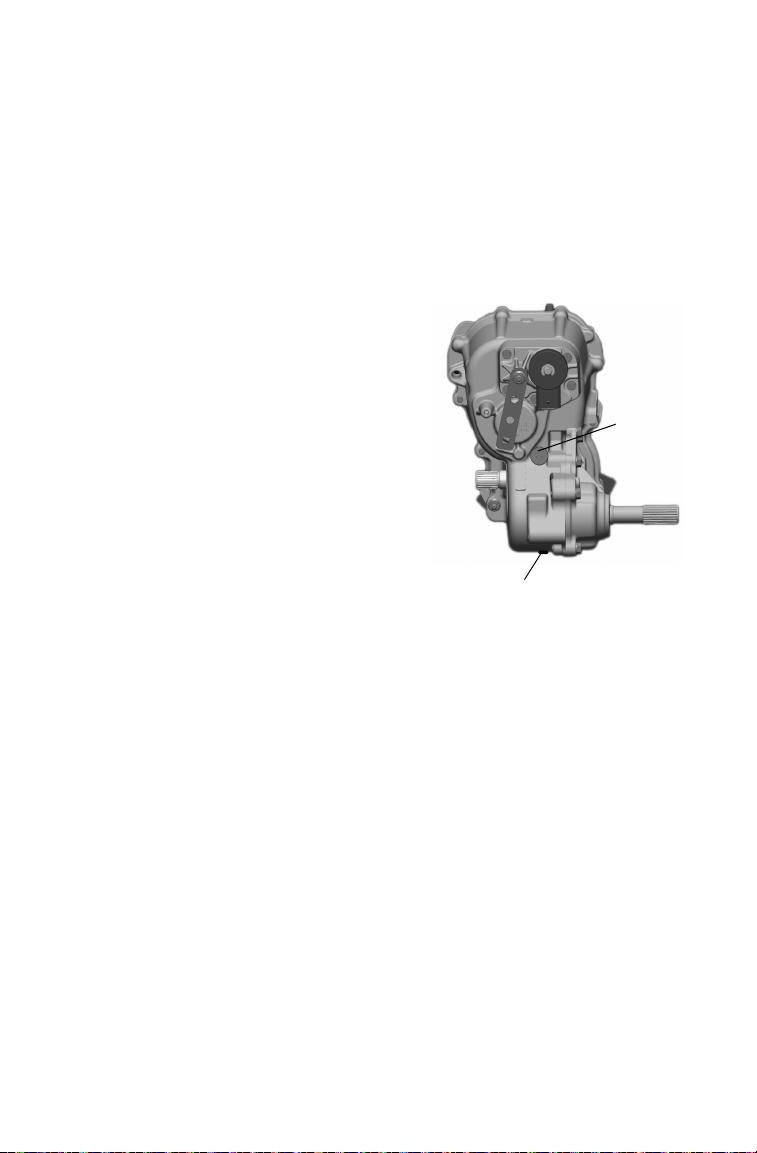
MAINTENANCE
Drain Plug
Fill
Plug
Gearcases
Transmission (Main Gearcase) (6X6)
Always check and change the transmission oil at the intervals outlined
in the Periodic Maintenance Chart beginning on page 62. Maintain the
oil level even with the bottom of the fill plug hole.
Refer to the Gearcase Specifications Chart on page 72 for recommended
lubricants, capacities and torque specifications. See page 116 for the
part numbers of Polaris products.
Oil Check
The fill plug is located at the rear of
the vehicle.
1. Position the vehicle on a level
surface.
2. Remove the fill plug.
3. Check the oil level.
4. Add the recommended oil as
needed.
5. Reinstall the fill plug. Torque to
specification.
Oil Change
The drain plug is located on the bottom of the transmission. Access the
drain plug through the drain hole in the skid plate.
1. Remove the fill plug.
2. Place a drain pan under the drain plug. Remove the drain plug.
Allow the oil to drain completely.
3. Wipe the magnetic end of the drain plug clean to remove accumulated metallic filings. Install a new sealing washer.
4. Reinstall the drain plug. Torque to specification.
5. Add the recommended oil. Do not overfill.
6. Reinstall the fill plug. Torque to specification.
7. Check for leaks. Dispose of used oil properly.
74
Page 79

MAINTENANCE
Drain
Plug
Fill
Plug
Gearcases
Front Gearcase
Always check and change the front gearcase oil at the intervals outlined
in the Periodic Maintenance Chart beginning on page 62. Maintain the
oil level even with the bottom thread of the fill plug hole.
Refer to the Gearcase Specifications Chart on page 72 for recommended
lubricants, capacities and torque specifications. See page 116 for the
part numbers of Polaris products.
Oil Check
The front gearcase fill plug is
located on the right side of the
front gearcase.
1. Position the vehicle on a level
surface.
2. Remove the fill plug. Check
the oil level.
3. Add the recommended oil as
needed.
4. Reinstall the fill plug. Torque
to specification.
Oil Change
1. Support the vehicle securely with a jackstand.
2. Remove the front tire on the driver's side.
3. Remove the fill plug.
4. Place a drain pan under the drain plug on the bottom right-hand
side.
5. Remove the drain plug. Allow the oil to drain completely.
6. Clean and reinstall the drain plug. Torque to specification.
7. Add the recommended oil.
8. Reinstall the fill plug. Torque to specification.
9. Check for leaks. Dispose of used oil properly.
75
Page 80

MAINTENANCE
Drain Plug
Fill Plug
Gearcases
Middle Gearcase (6X6)
Always check and change the middle gearcase oil at the intervals outlined in the Periodic Maintenance Chart beginning on page 62. Maintain
the oil level even with the bottom thread of the fill plug hole.
Refer to the Gearcase Specifications Chart on page 72 for recommended
lubricants, capacities and torque specifications. See page 116 for the
part numbers of Polaris products.
The middle gearcase fill plug is located on the side of the gearcase.
Oil Check
1. Position the vehicle on a
level surface.
2. Remove the fill plug. Check
the oil level.
3. Add the recommended oil as
needed.
4. Reinstall the fill plug. Torque
to specification.
Oil Change
1. Remove the fill plug.
2. Place a drain pan under the
drain plug.
3. Remove the drain plug.
Allow the oil to drain completely.
4. Clean and reinstall the drain plug. Torque to specification.
5. Add the recommended fluid.
6. Reinstall the fill plug. Torque to specification.
7. Check for leaks. Discard used oil properly.
76
Page 81

MAINTENANCE
Fill
Plug
Drain Plug
Gearcases
Rear Gearcase (6X6)
Always check and change the rear gearcase oil at the intervals outlined
in the Periodic Maintenance Chart beginning on page 62.
Refer to the Gearcase Specifications Chart on page 72 for recommended
lubricants, capacities and torque specifications. See page 116 for the
part numbers of Polaris products.
The rear gearcase fill plug is on the driver's side of the rear gearcase.
Oil Check
Maintain the oil level even with the
bottom thread of the fill plug hole.
1. Position the vehicle on a level
surface.
2. Remove the fill plug. Check the
oil level.
3. Add the recommended oil as
needed.
4. Reinstall the fill plug. Torque to
specification.
Oil Change
1. Remove the fill plug.
2. Place a drain pan under the drain plug.
3. Remove the drain plug. Allow the oil to drain completely.
4. Clean and reinstall the drain plug. Torque to specification.
5. Add the recommended oil.
6. Reinstall the fill plug. Torque to specification.
7. Check for leaks. Dispose of used oil properly.
77
Page 82

MAINTENANCE
Spark Plugs
Spark Plug Recommendations
Refer to the specifications section beginning on page 110 for the recommended spark plug type for your vehicle. Always torque spark plugs to
specification.
NOTICE: Using non-recommended spark plugs can result in serious engine
Spark Plug Gap/Torque
Spark Plug Inspection
Spark plug condition is indicative of engine operation. The spark plug
firing end condition should be read after the engine is warmed up and
the vehicle is driven at higher speeds. Immediately check the spark plug
for correct color.
CAUTION! A hot exhaust system and engine can cause burns. Wear
protective gloves when removing a spark plug for inspection.
1. Remove the seat. Remove the spark plug cap.
2. Using the spark plug wrench provided in the tool kit, remove the
3. Reverse the procedure for spark plug installation. Torque to specifi-
damage. Always use Polaris-recommended spark plugs.
Model Electrode Gap New Plug
All .035" (.9 mm) 18 ft. lbs.
To r q u e
(24 Nm)
plug by rotating it counterclockwise.
cation.
Used Plug
To r q u e
18 ft. lbs.
(24 Nm)
Normal Plug
The normal insulator tip is gray, tan or light brown. There will be few
combustion deposits. The electrodes are not burned or eroded. This indicates the proper type and heat range for the engine and the service.
The tip should not be white. A white insulator tip indicates overheating,
caused by use of an improper spark plug or incorrect throttle body
adjustments.
Wet Fouled Plug
The wet fouled insulator tip is black. A damp oil film covers the firing
end. There may be a carbon layer over the entire nose. Generally, the
electrodes are not worn. General causes of fouling are excessive oil, use
of non-recommended oil or incorrect throttle body adjustments.
78
Page 83

MAINTENANCE
Cooling System
The engine coolant level is controlled or maintained by the recovery
system. The recovery system components are the overflow bottle, radiator filler neck, radiator pressure cap and connecting hose.
As coolant operating temperature increases, the expanding (heated)
excess coolant is forced out of the radiator, past the pressure cap, and
into the overflow bottle. As engine coolant temperature decreases, the
contracting (cooled) coolant is drawn back up from the tank, past the
pressure cap, and into the radiator.
Some coolant level drop on new vehicles is normal as the system is
purging itself of trapped air. Observe coolant levels and maintain as recommended by adding coolant to the overflow bottle.
Adding or Changing Coolant
To ensure that the coolant maintains its ability to protect the engine, we
recommend that the system be completely drained every two years and a
fresh mixture of antifreeze and water added. Polaris recommends the
use of Polaris Premium 60/40 anti-freeze/coolant or a 50/50 mixture of
high quality aluminum compatible anti-freeze/coolant and distilled
water. Polaris Premium 60/40 is already premixed and ready to use. Do
not dilute with water. See page 116 for the part numbers of Polaris products.
Always follow the manufacturer's mixing recommendations for the
freeze protection required in your area.
Any time the cooling system has been drained for maintenance or repair,
replace the coolant. If the recovery bottle has run dry, the level in the
radiator should be inspected. Add coolant as needed.
79
Page 84

MAINTENANCE
Cooling System
Radiator and Cooling Fan
Always check and clean the screen and radiator fins at the intervals outlined in the Periodic Maintenance Chart beginning on page 62. Do not
obstruct or deflect air flow through the radiator by installing unauthorized accessories in front of the radiator or behind the cooling fan. Interference with the radiator air flow can lead to overheating and
consequent engine damage.
NOTICE: Washing the vehicle with a high-pressure hose could damage the
Overflow Bottle Coolant Level
Always check and change the coolant at the intervals outlined in the
Periodic Maintenance Chart beginning on page 62. Maintain the coolant
level between the minimum and maximum marks on the bottle (when
the fluid is cool).
The overflow bottle is located in front of the right front wheel.
1. Position the vehicle on a level surface.
2. View the coolant level in the overflow bottle.
3. If the coolant level is below the
Tip: If coolant must be added often, or if
radiator fins and impair the radiator's effectiveness. Using a highpressure system is not recommended.
safe operating range, lift the
hood and locate the overflow
bottle lid. Remove the cap and
use a funnel to add coolant
through the filler opening. Reinstall the cap.
the overflow bottle runs completely
dry, there may be a leak in the system. Have the cooling system
inspected by your Polaris dealer.
80
Page 85

MAINTENANCE
Cooling System
Radiator Coolant Level
1. Lift the hood.
CAUTION! Escaping steam
can cause burns. Never
remove the pressure cap while
the engine is warm or hot.
Always allow the engine to
cool before removing the
pressure cap.
2. Slowly remove the
radiator cap.
3. View the coolant level
through the opening.
4. Use a funnel and
slowly add coolant as needed.
Tip: This procedure is required only if the cooling system has been drained for
maintenance and/or repair. But if the overflow bottle has run dry, the level in
the radiator should also be inspected.
5. Reinstall the pressure cap. Use of a non-standard pressure cap will
not allow the recovery system to function properly. See your dealer
for the correct replacement part.
81
Page 86

MAINTENANCE
WARNING
Polaris Variable Transmission (PVT) System
Failure to comply with the instructions in this warning can result in severe injury
or death.
Do not modify any component of the PVT system. Doing so may reduce its
strength so that a failure may occur at a high speed. The PVT system has been
precision balanced. Any modification will cause the system to be out of balance,
creating vibration and additional loads on components.
The PVT system rotates at high speeds, creating large amounts of force on
clutch components. Extensive engineering and testing has been conducted to
ensure the safety of this product. However, as the owner, you have the following
responsibilities to make sure this system remains safe:
• Always follow all recommended maintenance procedures. See your dealer as
outlined in the owner's manual.
• This PVT system is intended for use on Polaris products only. Do not install it in
any other product.
• Always make sure the PVT housing is securely in place during operation.
When To Use Low Range and High Range
Belt slip is responsible for creating excessive heat that destroys belts,
wears clutch components and causes outer clutch covers to fail. Switch
to low range while operating at slower speeds to extend the life of the
PVT components (belt, cover, etc.).
Condition Range to Use
Operating at speeds less than 7 MPH (11 km/h) Low
Towing heavy loads Low
Operating in rough terrain (swamps, mountains, etc.) Low
Operating at speeds greater than 7 MPH (11 km/h) High
82
Page 87

MAINTENANCE
PVT System
PVT Drying
There may be some instances when water is accidently ingested into the
PVT system. Use the following instructions to dry it out before operating.
1. Position the vehicle on a level surface.
2. Remove the drain plug. Allow the water to drain completely. Reinstall the drain plug.
3. Apply the brakes. Start the engine.
4. Engage the park brake.
5. Shift the transmission to neutral.
6. Apply varying throttle for 10-15 seconds to expel the moisture and
air-dry the belt and clutches. Do not hold the throttle wide open for
more than 10 seconds.
7. Allow the engine RPM to settle to idle speed. Apply the service
brakes. Release the park brake and shift the transmission to the lowest available range.
8. Test for belt slippage. If the belt slips, repeat the process.
9. Take the vehicle to your dealer for service as soon as possible.
83
Page 88

MAINTENANCE
Vehicle Immersion
NOTICE: If your vehicle becomes immersed, major engine damage can result
If it's impossible to take your RANGER to a dealer before starting it, follow the steps outlined below.
1. Move the vehicle to dry land or at the very least, to water below the
2. Dry any water present in the air box. Filter replacement is required
3. Thoroughly dry the air pre-cleaner located under the hood.
4. Remove the spark plugs. Turn the engine over several times using
5. Dry the spark plugs and reinstall, or replace with new plugs.
6. Attempt to start the engine. If necessary, repeat the drying proce-
7. Take the vehicle to your dealer for service as soon as possible,
8. If water has been ingested into the PVT follow the procedure on
if the machine is not thoroughly inspected. Take the vehicle to your
dealer before starting the engine.
footrests.
if water is present.
the electric start.
dure.
whether you succeed in starting it or not.
page 83 for drying.
84
Page 89

MAINTENANCE
Air Filter
Filter Systems
Air Filter
Always change the air filter at the intervals outlined in the Periodic
Maintenance Chart beginning on page 62. Service the air filter more frequently if the vehicle is operated in wet conditions or at high throttle
openings for extended periods.
1. Lift the cargo box to
access the air box.
2. Remove the air box
cover and inspect the
gasket. It should adhere
tightly to the cover and
seal all the way around.
3. Remove the air filter.
4. Do not attempt to clean
the main element.
Install a new air filter.
Tip: Apply a small amount of
general purpose grease to
the sealing edges of the
filter before installing.
5. Inspect the air box for
oil or water deposits. If
present, drain them into a suitable container.
Fuel Filter
Your Polaris vehicle is equipped with an in-line fuel filter. Have your
dealer replace it after every 100 hours of operation. Do not attempt to
clean the fuel filter.
85
Page 90

MAINTENANCE
WARNING
Spark Arrestor
Failure to heed the following warnings while servicing the spark arrestor could
result in serious injury or death.
Do not perform service on the spark arrestor while the system is hot. Exhaust
system temperatures can reach 1000° F. Allow components to cool sufficiently
before proceeding.
Remove any combustible materials from the area.
Wear eye protection and gloves.
Do not stand behind or in front of the vehicle while purging.
Never run the engine in an enclosed area. Exhaust contains poisonous carbon
monoxide gas that can cause loss of consciousness or death in a very short
time.
Never go under the vehicle while it's inclined.
86
Page 91

MAINTENANCE
Clean-Out
Plugs
Exhaust
Outlet
Spark Arrestor
Use the following procedure to periodically purge accumulated carbon
from the exhaust pipe.
1. Remove the arrestor clean-out
plugs located on the bottom of the
muffler.
2. Place the transmission in neutral.
3. Engage the park brake.
4. Start the engine.
5. Purge accumulated carbon from
the system by momentarily revving the engine several times.
6. If carbon is expelled, cover or
plug the exhaust outlet and rap on
the pipe around the clean-out plugs while revving the engine several
more times.
7. If particles are still suspected to be in the muffler, elevate the rear of
the vehicle one foot higher than the front. Block the wheels.
8. Repeat steps 5 and 6 until no more particles are expelled when the
engine is revved.
9. Stop the engine. Allow the arrestor to cool.
10. Reinstall the arrestor plugs and remove the outlet cover or plug.
87
Page 92

MAINTENANCE
WARNING
Throttle
Pedal
Throttle System
Failure to check or maintain proper operation of the throttle system can result in
an accident and lead to serious injury or death if the throttle pedal sticks during
operation.
Always check the pedal for free movement and return before starting the engine
and occasionally during operation. Never start or operate this vehicle if it has a
sticking or improperly operating throttle pedal. Immediately contact your dealer
for service if throttle problems arise.
Throttle Freeplay
If the throttle pedal has excessive
play due to cable stretch or misadjustment, it will cause a delay
in throttle response, especially at
low engine speed. The throttle
may also not open fully. If the
throttle pedal has no freeplay, the
throttle may be hard to control,
and the idle speed may be erratic.
Check the throttle pedal freeplay
at the intervals outlined in the
Periodic Maintenance Chart
beginning on page 62. Adjust the
freeplay if necessary.
Throttle Freeplay Inspection
1. Apply the brakes. Engage the park brake. Shift the transmission to
neutral.
2. Start the engine. Allow it to warm up thoroughly.
3. Measure the distance the throttle pedal moves before the engine
begins to pick up speed. Freeplay should be 1/16 to 1/8 inches (1.6-
3.2 mm).
88
Page 93

MAINTENANCE
Boot
Adjuster
Lock Nut
Throttle System
Throttle Body/Idle RPM
Idle RPM is preset by the manufacturer. If the engine idle speed is not
satisfactory, please see your Polaris dealer for adjustment.
Throttle Freeplay Adjustment
1. Remove the seat.
2. Locate the throttle cable
adjuster.
3. Squeeze the end of the rubber boot and slide it far
enough to expose the end
of the inline cable adjuster.
4. Loosen the adjuster lock
nut.
5. Rotate the boot to turn the
adjuster until 1/16" to 1/8"
(1.5-3 mm) of freeplay is
achieved at the throttle
pedal. See page 88.
Tip: While adjusting, lightly flip the throttle pedal up and down.
6. Tighten the lock nut.
7. Squeeze the end of the rubber boot and slide it over the cable
adjuster to its original position.
89
Page 94

MAINTENANCE
Maximum
Minimum
Brakes
The front and rear brakes are hydraulic disc type brakes activated by the
brake pedal. See page 28.
Brake Fluid
Inspect the brake system routinely. Inspect the level of the brake fluid
before each operation.
WARNING! After opening a bottle of brake fluid, always discard any unused
portion. Never store or use a partial bottle. Brake fluid is hygroscopic, meaning it
rapidly absorbs moisture from the air. The moisture causes the boiling
temperature of the brake fluid to drop, which can lead to early brake fade and
the possibility of accident or severe injury.
Change the brake fluid every two years and any time the fluid becomes
contaminated, the fluid level is below the minimum, or if the type and
brand of the fluid in the reservoir are unknown.
1. Position the vehicle on a level
surface.
2. View the brake fluid level at the
reservoir in the driver’s side
wheel well.
3. The level should be between the
upper (MAX) and lower (MIN)
level lines.
4. If the fluid level is lower than
the upper level line, add brake
fluid to the upper (MAX) line.
5. Apply the brake forcefully for a
few seconds and check for fluid
leakage around the fittings.
90
Page 95

Brakes
3/64" (1mm)
Park Brake Release
Brake Inspection
1. Check the brake system for
fluid leaks.
2. Check the brake pedal for
excessive travel or a spongy
feel.
3. Check the friction pads for
wear, damage and looseness.
4. Inspect the brake disc spline
and pad wear surface for
excessive wear.
5. Change pads when worn to
3/64" (1 mm).
Park Brake Inspection
1. Apply the brakes.
2. Pull the park brake lever
downward as far as possible.
3. Check the vehicle for
movement. The vehicle
should not roll while parked.
If the vehicle moves, adjust
the park brake.
MAINTENANCE
91
Page 96

MAINTENANCE
Brakes
Park Brake Adjustment
Inspect and adjust park brake cable tension after the first 25 hours of
operation and every 100 hours thereafter to ensure proper cable tension.
Loss of tension in the park brake cable may cause illumination of the
park brake light and activation of the limiting feature. If this occurs,
move the park brake lever to the forward-most position, then inspect and
adjust park brake cable tension.
Tip: If performing this service is difficult due to conditions or location, open the
hood and temporarily disconnect the park brake connector. This will inactivate the limiting function. Reconnect the connector as soon as possible,
and adjust the park brake cable to proper tension.
1. Position the vehicle on a level surface.
2. Shift the transmission to neutral.
3. Loosen or tighten the nuts on the lever end of the park brake cable
as needed.
Steering Wheel Inspection
Check the steering wheel for specified freeplay and smooth operation at
the intervals outlined in the Periodic Maintenance Chart beginning on
page 62.
1. Position the vehicle on level ground.
2. Lightly turn the steering wheel left and right.
3. There should be 0.8"-1.0" (20-25 mm) of freeplay.
4. If there is excessive freeplay or strange noises, or the steering feels
rough or "catchy," have the steering system inspected by an authorized Polaris dealer.
92
Page 97

MAINTENANCE
Outside Mounting Holes
Inside Mounting Holes
Cam
Rear Suspension Shown
Adjustment is similar for Front Suspension
Suspension Adjustments
The front and rear suspensions can be adjusted to provide a stiffer suspension, if necessary.
1. Remove the top shock mounting bolts from the inside mounting
holes.
2. Reposition the shocks to the outside mounting holes.
3. Reinstall the shock mounting bolts. Torque to 30 ft. lbs. (40 Nm).
Spring Adjustment
Adjust the front and rear shock absorber springs by rotating the adjustment cam either clockwise or counterclockwise to increase or decrease
spring tension.
93
Page 98

MAINTENANCE
WARNING
1/8" (3 mm)
Tires
Operating your vehicle with worn tires, improperly inflated tires, non-standard
tires or improperly installed tires will affect vehicle handling and could cause an
accident resulting in serious injury or death. Always follow all tire maintenance
procedures as outlined in this manual and on the labels on the vehicle. Always
use original equipment size and type when replacing tires.
Tire Tread Depth
Always replace tires
when tread depth is
worn to 1/8" (3 mm)
or less.
Axle and Wheel Nut Torque Specifications
Inspect the following items occasionally for tightness, and if they've
been loosened for maintenance service.
Do not lubricate the stud or the lug nut.
Nut Type Location Nut Torque
Lug Nut Front and Rear 90 ft. lbs. (122 Nm)
2-Piece Flange
Nut
Spindle Nut Front 70 ft. lbs. (95 Nm)
Hub Retaining Nuts Center and Rear 110 ft. lbs. (150 Nm)
94
Front and Rear 35 ft. lbs. (47 Nm)
Page 99

MAINTENANCE
Tires
Wheel Removal
1. Apply the brakes. Engage the park brake.
2. Stop the engine. Place the transmission in gear.
3. Loosen the wheel nuts slightly.
4. Elevate the side of the vehicle by placing a suitable stand under the
frame.
5. Remove the wheel nuts and washers. Remove the wheel.
Wheel Installation
1. Apply the brakes.
2. Place the transmission
in gear.
3. Engage the park brake.
4. Place the wheel in the
correct position on the
wheel hub. Be sure the
valve stem is toward
the outside and rotation arrows on the tire
point toward forward
rotation.
WARNING! Improperly installed wheels can adversely affect tire wear and
vehicle handling, which can result in serious injury or death. Always ensure that
all nuts are torqued to specification. Do not service axle nuts that have a cotter
pin installed. See your Polaris dealer.
5. Attach the wheel nuts and washers and finger tighten.
6. Carefully lower the vehicle to the ground.
7. Torque the wheel nuts to specification. See page 94.
95
Page 100

MAINTENANCE
Wiring Harness
Lights
Poor lighting can result in reduced visibility when driving. Headlight
and taillight lenses become dirty during normal operation. Clean lights
frequently and replace burned out lamps promptly. Always make sure
lights are adjusted properly for best visibility.
When servicing a halogen lamp, don't touch the lamp with bare fingers.
Oil from your skin leaves a residue, causing a hot spot that will shorten
the life of the lamp.
Headlight Lamp Replacement
1. Open the hood.
CAUTION! Hot components
can cause burns to skin. Allow
lamps to cool before servicing.
2. Unplug the headlamp
from the wiring harness.
Be sure to pull on the
connector, not on the
wiring.
3. Turn the lamp counterclockwise to remove it.
4. Install the new lamp.
Tip: Make sure the tab on the lamp locates properly in the housing.
5. Reinstall the harness assembly into the headlight assembly.
Brake Lights
When the brake pedal is depressed, the console brake light comes on.
Check the brake light before each ride.
1. Turn the ignition switch to the ON position.
2. Depress the brake pedal. The brake light should come on after about
10 mm (0.4 in.) of pedal travel. If the light doesn't come on, check
the bulb.
96
 Loading...