

Page 1

2015-2016 RANGER EV
Service Manual
The information printed within this publication includes the latest product information at time of print. The most recent
version of this Service Manual is available in electronic format at www.polarisdealers.com.
This Service Manual is designed primarily for use by certified Polaris Master Service Dealer
equipped shop and should be kept available for reference. All references to left and right side of the vehicle are from
the operator's perspective when seated in a normal riding position.
Some procedures outlined in this manual require a sound knowledge of mechanical theory, tool use, and shop
procedures in order to perform the work safely and correctly. Technicians should read the text and be familiar with the
service procedures before starting any repair. Certain procedures require the use of special tools. Use only the proper
tools as specified. If you have any doubt as to your ability to perform any of the procedures outlined in this Service
Manual, contact an authorized dealer for service.
We value your input and appreciate any assistance you can provide in helping make these publications more useful.
Please provide any feedback you may have regarding this manual. Authorized dealers can submit feedback using 'Ask
Polaris'. Click on 'Ask Polaris', and then click on 'Service Manual / Service Literature Question'.
Consumers, please provide your feedback in writing to: Polaris Industries Inc. ATTN: Service Publications Department,
2100 Hwy 55, Medina, MN 55340.
FOREWORD
®
technicians in a properly
Publication Printed August 2015 (PN 9926595 R01)
© Copyright 2015 Polaris Industries Inc. All information contained within this publication is based on the latest product information at the time of publication. Due to
constant improvements in the design and quality of production components, some minor discrepancies may result between the actual vehicle and the information
presented in this publication. Depictions and/or procedures in this publication are intended for reference use only. No liability can be accepted for omissions or
inaccuracies. Any reprinting or reuse of the depictions and/or procedures contained within, whether whole or in part, is expressly prohibited. Printed in U.S.A.
Page 2

UNDERSTANDING SAFETY LABELS AND DIRECTIONS
Throughout this manual, important information is brought to your attention by the following symbols:
WARNING
SAFETY ALERT WARNING indicates a potential hazard that may result in severe injury or death to the operator,
bystander or person(s) inspecting or servicing the vehicle.
CAUTION
SAFETY ALERT CAUTION indicates a potential hazard that may result in minor personal injury or damage to the
vehicle.
CAUTION
CAUTION indicates special precautions that must be taken to avoid vehicle damage or property damage.
NOTE
NOTE provides key information by clarifying instructions.
IMPORTANT
IMPORTANT provides key reminders during disassembly, assembly and inspection of components.
Page 3

TRADEMARKS
POLARIS ACKNOWLEDGES THE FOLLOWING PRODUCTS MENTIONED IN THIS MANUAL:
Loctite, Registered Trademark of the Loctite Corporation
Nyogel, Trademark of Wm. F. Nye Co.
Fluke, Registered Trademark of John Fluke Mfg. Co.
Mity-Vac, Registered Trademark of Neward Enterprises, Inc.
Torx, Registered Trademark of Textron
Hilliard, Trademark of the Hilliard Corporation
Warn, Trademark of Warn Industries
FOX, Registered Trademark of FOX RACING SHOX
RydeFX, Registered Trademark of ArvinMeritor
Some Polaris factory publications can be downloaded from www.polarisindustries.com, purchased from
www.purepolaris.com or by contacting the nearest Polaris dealer.
Page 4

Page 5

2015-2016 RANGER EV
Service Manual
Chapter Summary
CHAPTER 1: GENERAL / BATTERY
CHAPTER 2: MAINTENANCE
CHAPTER 3: DRIVE MOTOR
CHAPTER 4: BODY / STEERING / SUSPENSION
CHAPTER 5: FINAL DRIVE
CHAPTER 6: TRANSAXLE / DIFFERENTIAL
CHAPTER 7: BRAKE SYSTEM
CHAPTER 8: ELECTRICAL
Page 6

Page 7

GENERAL / BATTERY
CHAPTER 1
GENERAL / BATTERY
SPECIAL INFORMATION REGARDING THE RANGER EV .. . . . . . . . . . . . . . . . . . . . . . . . . . . . . . . . . . . . . . . . . . 1.3
OPERATING THE RANGER EV. . . . . . . . . . . . . . . . . . . . . . . . . . . . . . . . . . . . . . . . . . . . . . . . . . . . . . . . . . . . . . . . . . . . . . . . 1.3
WORKING ON THE RANGER EV. . . . . . . . . . . . . . . . . . . . . . . . . . . . . . . . . . . . . . . . . . . . . . . . . . . . . . . . . . . . . . . . . . . . . . 1.3
VEHICLE TOWING . . . . . . . . . . . . . . . . . . . . . . . . . . . . . . . . . . . . . . . . . . . . . . . . . . . . . . . . . . . . . . . . . . . . . . . . . . . . . . . . . . . . 1.3
VEHICLE IDENTIFICATION . . . . . . . . . . . . . . . . . . . . . . . . . . . . . . . . . . . . . . . . . . . . . . . . . . . . . . . . . . . . . . . . . . . . . . . . . . . . . 1.4
MODEL NUMBER DESIGNATION . . . . . . . . . . . . . . . . . . . . . . . . . . . . . . . . . . . . . . . . . . . . . . . . . . . . . . . . . . . . . . . . . . . . . 1.4
VEHICLE IDENTIFICATION NUMBER (VIN) DESIGNATION. . . . . . . . . . . . . . . . . . . . . . . . . . . . . . . . . . . . . . . . . . . . 1.4
VEHICLE AND MOTOR SERIAL NUMBER LOCATIONS .. . . . . . . . . . . . . . . . . . . . . . . . . . . . . . . . . . . . . . . . . . . . . . 1.5
VEHICLE INFORMATION . . . . . . . . . . . . . . . . . . . . . . . . . . . . . . . . . . . . . . . . . . . . . . . . . . . . . . . . . . . . . . . . . . . . . . . . . . . . . . . . 1.6
PUBLICATION NUMBERS . . . . . . . . . . . . . . . . . . . . . . . . . . . . . . . . . . . . . . . . . . . . . . . . . . . . . . . . . . . . . . . . . . . . . . . . . . . . . 1.6
REPLACEMENT KEYS . . . . . . . . . . . . . . . . . . . . . . . . . . . . . . . . . . . . . . . . . . . . . . . . . . . . . . . . . . . . . . . . . . . . . . . . . . . . . . . . 1.7
SPECIAL TOOLS . . . . . . . . . . . . . . . . . . . . . . . . . . . . . . . . . . . . . . . . . . . . . . . . . . . . . . . . . . . . . . . . . . . . . . . . . . . . . . . . . . . . . . 1.7
GENERAL SPECIFICATIONS ... . . . . . . . . . . . . . . . . . . . . . . . . . . . . . . . . . . . . . . . . . . . . . . . . . . . . . . . . . . . . . . . . . . . . . . . . 1.8
2015 - 2016 RANGER EV.. . . . . . . . . . . . . . . . . . . . . . . . . . . . . . . . . . . . . . . . . . . . . . . . . . . . . . . . . . . . . . . . . . . . . . . . . . . . . 1.8
FEATURES AND CONTROLS . . . . . . . . . . . . . . . . . . . . . . . . . . . . . . . . . . . . . . . . . . . . . . . . . . . . . . . . . . . . . . . . . . . . . . . . . . 1.11
CONSOLE . . . . . . . . . . . . . . . . . . . . . . . . . . . . . . . . . . . . . . . . . . . . . . . . . . . . . . . . . . . . . . . . . . . . . . . . . . . . . . . . . . . . . . . . . . . 1.11
KEY SWITCH. . . . . . . . . . . . . . . . . . . . . . . . . . . . . . . . . . . . . . . . . . . . . . . . . . . . . . . . . . . . . . . . . . . . . . . . . . . . . . . . . . . . . . . . . 1.11
PARKING BRAKE . . . . . . . . . . . . . . . . . . . . . . . . . . . . . . . . . . . . . . . . . . . . . . . . . . . . . . . . . . . . . . . . . . . . . . . . . . . . . . . . . . . . 1.11
BATTERY DISCHARGE INDICATOR.. . . . . . . . . . . . . . . . . . . . . . . . . . . . . . . . . . . . . . . . . . . . . . . . . . . . . . . . . . . . . . . . .1.12
CHARGE STATUS INDICATOR . . . . . . . . . . . . . . . . . . . . . . . . . . . . . . . . . . . . . . . . . . . . . . . . . . . . . . . . . . . . . . . . . . . . . . .1.13
BATTERY CHARGING CORD / BATTERY CHARGER.. . . . . . . . . . . . . . . . . . . . . . . . . . . . . . . . . . . . . . . . . . . . . . . .1.13
HEADLIGHT SWITCH .. . . . . . . . . . . . . . . . . . . . . . . . . . . . . . . . . . . . . . . . . . . . . . . . . . . . . . . . . . . . . . . . . . . . . . . . . . . . . . .1.13
HOUR METER . . . . . . . . . . . . . . . . . . . . . . . . . . . . . . . . . . . . . . . . . . . . . . . . . . . . . . . . . . . . . . . . . . . . . . . . . . . . . . . . . . . . . . .1.14
12 VOLT AUXILIARY POWER OUTLET . . . . . . . . . . . . . . . . . . . . . . . . . . . . . . . . . . . . . . . . . . . . . . . . . . . . . . . . . . . . . . .1.14
AUXILIARY 12 VOLT TERMINAL BOARD . . . . . . . . . . . . . . . . . . . . . . . . . . . . . . . . . . . . . . . . . . . . . . . . . . . . . . . . . . . . .1.14
DIRECTION SELECTOR SWITCH . . . . . . . . . . . . . . . . . . . . . . . . . . . . . . . . . . . . . . . . . . . . . . . . . . . . . . . . . . . . . . . . . . . .1.14
ALL WHEEL DRIVE (AWD) SWITCH . . . . . . . . . . . . . . . . . . . . . . . . . . . . . . . . . . . . . . . . . . . . . . . . . . . . . . . . . . . . . . . . . . 1.14
INDICATOR LIGHT PANEL . . . . . . . . . . . . . . . . . . . . . . . . . . . . . . . . . . . . . . . . . . . . . . . . . . . . . . . . . . . . . . . . . . . . . . . . . . .1.16
WINDSHIELD . . . . . . . . . . . . . . . . . . . . . . . . . . . . . . . . . . . . . . . . . . . . . . . . . . . . . . . . . . . . . . . . . . . . . . . . . . . . . . . . . . . . . . . .1.17
INDEX TO BATTERY INFORMATION . . . . . . . . . . . . . . . . . . . . . . . . . . . . . . . . . . . . . . . . . . . . . . . . . . . . . . . . . . . . . . . . .1.17
TROUBLESHOOTING - VEHICLE OPERATION. . . . . . . . . . . . . . . . . . . . . . . . . . . . . . . . . . . . . . . . . . . . . . . . . . . . . . .1.17
BATTERY SAFETY . . . . . . . . . . . . . . . . . . . . . . . . . . . . . . . . . . . . . . . . . . . . . . . . . . . . . . . . . . . . . . . . . . . . . . . . . . . . . . . . . . . . . .1.18
PROPOSITION 65 WARNING . . . . . . . . . . . . . . . . . . . . . . . . . . . . . . . . . . . . . . . . . . . . . . . . . . . . . . . . . . . . . . . . . . . . . . . .1.18
BATTERY CHARGING WARNING . . . . . . . . . . . . . . . . . . . . . . . . . . . . . . . . . . . . . . . . . . . . . . . . . . . . . . . . . . . . . . . . . . . .1.18
BATTERY CAUTION. . . . . . . . . . . . . . . . . . . . . . . . . . . . . . . . . . . . . . . . . . . . . . . . . . . . . . . . . . . . . . . . . . . . . . . . . . . . . . . . . .1.18
BATTERY COMPARTMENT WARNING LABEL . . . . . . . . . . . . . . . . . . . . . . . . . . . . . . . . . . . . . . . . . . . . . . . . . . . . . . .1.19
BATTERY MAINTENANCE . . . . . . . . . . . . . . . . . . . . . . . . . . . . . . . . . . . . . . . . . . . . . . . . . . . . . . . . . . . . . . . . . . . . . . . . . . . . .1.20
TO MAXIMIZE BATTERY SERVICE LIFE .. . . . . . . . . . . . . . . . . . . . . . . . . . . . . . . . . . . . . . . . . . . . . . . . . . . . . . . . . . . .1.20
BATTERYACCESS. . . . . . . . . . . . . . . . . . . . . . . . . . . . . . . . . . . . . . . . . . . . . . . . . . . . . . . . . . . . . . . . . . . . . . . . . . . . . . . . . . . 1.20
MAIN POWER CONNECTOR. . . . . . . . . . . . . . . . . . . . . . . . . . . . . . . . . . . . . . . . . . . . . . . . . . . . . . . . . . . . . . . . . . . . . . . . .1.20
BATTERY TERMINAL FASTENER TORQUE . . . . . . . . . . . . . . . . . . . . . . . . . . . . . . . . . . . . . . . . . . . . . . . . . . . . . . . . . .1.20
BATTERY CONTACTOR FASTENER TORQUE . . . . . . . . . . . . . . . . . . . . . . . . . . . . . . . . . . . . . . . . . . . . . . . . . . . . . . .1.21
1
9926595 R01 - 2015-2016 RANGER EV Service Manual
© Copyright Polaris Industries Inc.
1.1
Page 8

GENERAL / BATTERY
BATTERY CLEANING (EXTERNAL SURFACES). . . . . . . . . . . . . . . . . . . . . . . . . . . . . . . . . . . . . . . . . . . . . . . . . . . . . . . . . . .1.21
BATTERY TERMINAL CLEANING . . . . . . . . . . . . . . . . . . . . . . . . . . . . . . . . . . . . . . . . . . . . . . . . . . . . . . . . . . . . . . . . . . . . . . . . .1.21
BATTERY CHARGING. . . . . . . . . . . . . . . . . . . . . . . . . . . . . . . . . . . . . . . . . . . . . . . . . . . . . . . . . . . . . . . . . . . . . . . . . . . . . . . . . . . . . 1.21
BATTERY WATER LEVEL . . . . . . . . . . . . . . . . . . . . . . . . . . . . . . . . . . . . . . . . . . . . . . . . . . . . . . . . . . . . . . . . . . . . . . . . . . . . . . . . .1.22
BATTERY TESTING - OVERVIEW . . . . . . . . . . . . . . . . . . . . . . . . . . . . . . . . . . . . . . . . . . . . . . . . . . . . . . . . . . . . . . . . . . . . . . . . .1.23
BASIC DISCHARGER INSTRUCTIONS. . . . . . . . . . . . . . . . . . . . . . . . . . . . . . . . . . . . . . . . . . . . . . . . . . . . . . . . . . . . . . . . . . . .1.24
BATTERY DISCHARGE AND TESTING PROCEDURE. . . . . . . . . . . . . . . . . . . . . . . . . . . . . . . . . . . . . . . . . . . . . . . . . . . . .1.25
BATTERY SPECIFIC GRAVITY TEST. . . . . . . . . . . . . . . . . . . . . . . . . . . . . . . . . . . . . . . . . . . . . . . . . . . . . . . . . . . . . . . . . . . . . .1.27
BATTERY REMOVAL AND INSTALLATION . . . . . . . . . . . . . . . . . . . . . . . . . . . . . . . . . . . . . . . . . . . . . . . . . . . . . . . . . . . . . . . .1.28
BATTERY TERMINAL ORIENTATION AND CABLE ROUTING.. . . . . . . . . . . . . . . . . . . . . . . . . . . . . . . . . . . . . . . . . . . . . 1.29
BATTERY CABLE REMOVAL . . . . . . . . . . . . . . . . . . . . . . . . . . . . . . . . . . . . . . . . . . . . . . . . . . . . . . . . . . . . . . . . . . . . . . . . . . . . . .1.31
BATTERY CABLE INSTALLATION . . . . . . . . . . . . . . . . . . . . . . . . . . . . . . . . . . . . . . . . . . . . . . . . . . . . . . . . . . . . . . . . . . . . . . . . .1.32
BATTERY STORAGE . . . . . . . . . . . . . . . . . . . . . . . . . . . . . . . . . . . . . . . . . . . . . . . . . . . . . . . . . . . . . . . . . . . . . . . . . . . . . . . . . . . . . .1.33
ACCESSORY INSTALLATION PRECAUTIONS . . . . . . . . . . . . . . . . . . . . . . . . . . . . . . . . . . . . . . . . . . . . . . . . . . . . . . . . . . . .1.33
BATTERY CHARGER . . . . . . . . . . . . . . . . . . . . . . . . . . . . . . . . . . . . . . . . . . . . . . . . . . . . . . . . . . . . . . . . . . . . . . . . . . . . . . . . . . . . .1.33
BATTERY CHARGER LED FUNCTION . . . . . . . . . . . . . . . . . . . . . . . . . . . . . . . . . . . . . . . . . . . . . . . . . . . . . . . . . . . . . . . . . . . .1.34
BATTERY CHARGER TROUBLESHOOTING . . . . . . . . . . . . . . . . . . . . . . . . . . . . . . . . . . . . . . . . . . . . . . . . . . . . . . . . . . . . . .1.34
SPECIFIC GRAVITY / CHARGE PERCENTAGE TABLE . . . . . . . . . . . . . . . . . . . . . . . . . . . . . . . . . . . . . . . . . . . . . . . . . . . .1.35
REFERENCE . . . . . . . . . . . . . . . . . . . . . . . . . . . . . . . . . . . . . . . . . . . . . . . . . . . . . . . . . . . . . . . . . . . . . . . . . . . . . . . . . . . . . . . . . . . . . . . . .1.36
CONVERSION TABLE.. . . . . . . . . . . . . . . . . . . . . . . . . . . . . . . . . . . . . . . . . . . . . . . . . . . . . . . . . . . . . . . . . . . . . . . . . . . . . . . . . . . . 1.36
STANDARD BOLT TORQUE SPECIFICATION .. . . . . . . . . . . . . . . . . . . . . . . . . . . . . . . . . . . . . . . . . . . . . . . . . . . . . . . . . . . .1.37
METRIC BOLT TORQUE SPECIFICATION... . . . . . . . . . . . . . . . . . . . . . . . . . . . . . . . . . . . . . . . . . . . . . . . . . . . . . . . . . . . . . .1.37
SAE TAP / DRILL SIZES . . . . . . . . . . . . . . . . . . . . . . . . . . . . . . . . . . . . . . . . . . . . . . . . . . . . . . . . . . . . . . . . . . . . . . . . . . . . . . . . . . .1.37
METRIC TAP / DRILL SIZES . . . . . . . . . . . . . . . . . . . . . . . . . . . . . . . . . . . . . . . . . . . . . . . . . . . . . . . . . . . . . . . . . . . . . . . . . . . . . . .1.38
DECIMAL EQUIVALENTS ... . . . . . . . . . . . . . . . . . . . . . . . . . . . . . . . . . . . . . . . . . . . . . . . . . . . . . . . . . . . . . . . . . . . . . . . . . . . . . .1.38
1.2
9926595 R01 - 2015-2016 RANGER EV Service Manual
© Copyright Polaris Industries Inc.
Page 9

SPECIAL INFORMATION REGARDING THE RANGER EV
OPERATING THE RANGER EV
If you are not familiar with the controls, features, or safe
operation of RANGER EV vehicles, read the Owner’s
Manual thoroughly before you operate the vehicle.
If you are an experienced RANGER EV technician and
have read and become familiar with safe vehicle
operation, a basic description of the switches and
controls unique to the RANGER EV is included in this
manual.
WORKING ON THE RANGER EV
Improper contact between battery terminals can result in
electrical shorts. Electrical shorts can result in burns.
WARNING
Use insulated tools or insulate any tools used within the
battery area to prevent sparks or battery explosion
caused by shorting the battery terminals or wiring.
Remove the batteries or cover the exposed terminals
with an insulating material.
The RANGER EV is equipped with eight 12-volt lead/acid
batteries arranged in two banks of four batteries each.
Each bank of batteries delivers 48 volts to a high
efficiency AC induction motor via the motor controller unit
and a key switch-controlled main contactor. Batteries,
controller, and contactor are located under the seat. Here
are a few key differences to remember when working on
the RANGER EV.
48 VOLT FUSES AND RELAYS
Be aware that some of the fuses and relays on the
RANGER EV are 48 volt; they may look similar to their 12
volt counterparts, but they are not the same and must not
be substituted with other types. The fuse voltage and
current rating is clearly marked on the fuse box label.
Refer to Chapter 8 of this manual (Electrical) for more
information and diagnostics for electrical system
components. Battery information is in this chapter
(Chapter 1).
GENERAL SAFETY REMINDERS
Wear the proper protective gear. Shield your eyes when
working on the RANGER EV.
Working on or around lead-acid batteries can be
dangerous if you do not take precautions and follow
proper handling, charging, and service procedures while
you work. Read the entire BATTERY SAFETY section of
this manual.
Remove all jewelry or metal objects that could come in
contact with battery terminals as you work in or around
the battery compartment; including (but not limited to):
• Rings, chains, wrist watches, bracelets, etc.
If battery access is not required for the task at hand,
keep storage trays and the seat in place to reduce the
chance of a dropped tool or other conductive object
making contact with the battery cables or terminals.
MAIN POWER CONNECTOR / BATTERY CHARGER
Some service procedures require special precautionary
steps to reduce the chance of electrical shorts and avoid
damage to expensive components. Always read and
understand the entire procedure and be sure you have
the proper tools and equipment before you begin. DO
NOT disconnect or work on any electrical component
without first disconnecting the Main Power Connector.
See Main Power Connector, page 1.20. DO NOT work on
the vehicle with the battery charger connected.
“FLOATING” CHASSIS
The RANGER EV frame and other chassis components
ARE NOT used as a conductor (ground path) for
electrical components and therefore not at ground
potential. NEVER connect accessories or other wiring to
the frame or chassis. Accessory Installation Precautions,
page 1.33. NEVER work on the vehicle with the battery
charger connected.
TIRE PRESSURE
Tire pressure for all tires is 20 psi (138 kPa) due to the
tire design used on the RANGER EV.
VEHICLE TOWING
When towing the vehicle, the key MUST be in the OFF
position or severe motor damage will occur.
1. Place direction selector in NEUTRAL
2. Turn key switch OFF.
3. Verify the parking brake is not engaged.
GENERAL / BATTERY
1
CAUTION
9926595 R01 - 2015-2016 RANGER EV Service Manual
© Copyright Polaris Industries Inc.
1.3
Page 10

GENERAL / BATTERY
VEHICLE IDENTIFICATION
MODEL NUMBER DESIGNATION
Example: A14KA09AD
GROUP
1st 2nd 3rd 4th* 5th* 6th* 7th* 8th* 9th** 10th
A 1 4 K A 0 9 A D
* = digits that would transfer to 17 digit VIN and are used in digits 4-8 respectively
** = 9th digit will be used on color/featured versions of models (not including the base)
First 3 digits and 9th digit are used in model number only. They are not used with the 17 digit VIN.
Digits 1 through 8 determine Digital Wrench calibration.
MODEL
YEAR
CHASSIS
DRIVE-
LINE
ENGINE /
MOTOR CODE
CATEGORY OPTION REGION
VEHICLE IDENTIFICATION NUMBER (VIN) DESIGNATION
Example: 4XAKA09A0E3000000
VEHICLE DESCRIPTORS VEHICLE IDENTIFIERS
WORLD MFG. ID
ENGINE
MODIFIER
ENGINE SIZE
CATEGORY
CHECK DIGIT
MODEL YEAR *
MFG. LOCATION
1 2 3 4
CHASSIS
DRIVELINE
5 6 7 8 9 10 11 12 13 14 15 16 17
4 X A K A 0 9 A 0 E 3 0 0 0 0 0 0
* Model Year: A = 2010; B = 2011; C = 2012; D = 2013; E = 2014; F = 2015; G = 2016
INDIVIDUAL SERIAL NO.
1.4
9926595 R01 - 2015-2016 RANGER EV Service Manual
© Copyright Polaris Industries Inc.
Page 11

GENERAL / BATTERY
VEHICLE AND MOTOR SERIAL NUMBER LOCATIONS
Whenever corresponding about a Polaris utility vehicle, be sure to refer to the vehicle identification number (VIN) and
the motor model and serial number.
The VIN can be found stamped on the lower frame rail on the front LH side of the vehicle and on the dash in front of the
steering wheel (see Figure 1-1).
The drive motor model and serial number can be found on a label (A) applied to the motor (see Figure 1-2).
1
9926595 R01 - 2015-2016 RANGER EV Service Manual
© Copyright Polaris Industries Inc.
1.5
Page 12

GENERAL / BATTERY
VEHICLE INFORMATION
PUBLICATION NUMBERS
MODEL MODEL NO.
R15RMAE4EJ 9925678 9925783
2015 RANGER EV
2016 RANGER EV
R15RMAE4GC 9925678 9925783
R15RMAE4GJ 9925678 9925783
R16RMAE4G8 9926456 9926474
R16RMAE4G9 9926456 9926474
NOTE
When ordering service parts be sure to use the correct
Polaris factory publications can be found at www.
polarisindustries.com or purchased from www.
parts manual.
purepolaris.com.
OWNER’S MANUAL
PN
PARTS MANUAL PN
1.6
9926595 R01 - 2015-2016 RANGER EV Service Manual
© Copyright Polaris Industries Inc.
Page 13

REPLACEMENT KEYS
Replacement keys can be made from the original key. To
identify which series the key is, take the first two digits on
the original key and refer to the chart to the right for the
proper part number.
SERIES# PART NUMBER
20 4010278
21 4010278
22 4010321
23 4010321
27 4010321
28 4010321
31 4110141
32 4110148
67 4010278
68 4010278
GENERAL / BATTERY
1
SPECIAL TOOLS
Special tools may be required while servicing this
vehicle. Some of the tools listed or depicted are
mandatory, while other tools maybe substituted with a
similar tool, if available. Polaris recommends the use of
Polaris Special Tools when servicing any Polaris product.
Dealers may order special tools through Polaris’ official
tool supplier, Bosch Automotive Service Solutions, by
phone at 1-800-345-2233 or on-line at http://polaris.
service-solutions. com/. A link to Bosch Automotive
Service Solutions is also provided under the Service &
Warranty tab at www.polarisdealers.com.
WARNING
Use insulated tools or insulate any tools used within the
battery area to prevent sparks or battery explosion
caused by shorting the battery terminals or wiring.
Remove the batteries or cover the exposed terminals
9926595 R01 - 2015-2016 RANGER EV Service Manual
© Copyright Polaris Industries Inc.
with an insulating material.
1.7
Page 14

GENERAL / BATTERY
GENERAL SPECIFICATIONS
2015 - 2016 RANGER EV
MODEL NUMBERS: 2015: R15RMAE4EJ / R15RMAE4GC / R15RMAE4GJ
2016: R16RMAE4G8 / R16RMAE4G9
CATEGORY DIMENSION / CAPACITY
Length
Width 56.5 in. / 143.5 cm
Height
Wheel Base 72 in. / 182.9 cm
Ground Clearance 10 in. / 25.4 cm
Turning Radius
Dry Weight 1750 lbs. / 793.8 kg
Gross Vehicle
Weight
Cargo System
Cargo Box
Dimensions
(Inside dimensions
inches /
centimeters)
Cargo Box Capacity 500 lbs. / 226.8 kg
Vehicle Payload
Towing With The RANGER EV
Hitch Towed Load
Weight (Level
ground)
Hitch Towed Load
Weight (15 degree
grade)
Hitch Vertical
Weight Capacity
Maximum Towing
Speed
108 in. / 274.3 cm
73 in. / 185.4 cm
150 in. / 381 cm
2750 lbs. / 1247 kg
Lock & Ride
Length: 32.0 / 81.3
Width: 42 / 107
Height: 11.5 / 29
1000 lbs. / 454 kg
(Includes weight of operator,
passenger, cargo and accessories)
1250 lbs. / 567 kg
850 lbs. / 386 kg
150 lbs. / 68 kg
10 mph. / 16 kph
®
1.8
9926595 R01 - 2015-2016 RANGER EV Service Manual
© Copyright Polaris Industries Inc.
Page 15

GENERAL / BATTERY
DRIVE MOTOR & ELECTRICAL
Motor Configuration
Motor Peak
Modes
Controller
Battery Pack
Maximum Speed 25 MPH (40 km/h)
Throttle
On-board Charger
Charge Time
Electrical
Charge Indicator
Hour Meter
Indicator Lights
Auxiliary Power 12 volt Accessory Outlet
Lights: Main Headlights
Tail Light / Brake Light
Chassis
Single 48 Volt High Efficiency AC
Induction Motor
30 HP (22.4 kW)
3 Modes:
High for performance
Low for pulling / towing
Max for maximum distance
650 Amp Sevcon Gen 4 controller
with multi-mode driving and
regenerative braking
11.7 kW battery pack at 48Vdc with
(8) 12 volt, US12VXC batteries in
series-parallel configuration.
Redundant, non-contact, inductivesensing pedal
Delta Q 120 volt AC input;
48 volt DC output
8 Hours (dependant on depth of
discharge)
Digital - Indicates Battery
State-of-Charge
Digital - Indicates Cumulative
Hours Of Vehicle Movement
Directional selection, Park Brake,
Motor or Controller Malfunction
Dual 50 Watt
Sealed LED
Floating - no ground connection.
NOTE: When the vehicle batteries
are being charged the chassis is at
ground potential. Do not work on
the vehicle when the battery
charger is connected to an
electrical outlet.
DRIVE TRAIN
Final Drive
Shift Type
Drive System
Drive Ratio - Front 3.81:1
Drive Ratio - Rear 20.56:1
Front Gearcase
Lubricant Requirement
Front Gearcase Fill Plug
Torque
Front Gearcase Drain
Plug Torque
Rear Gearcase
Rear Gearcase
(Transaxle) Lubricant
Rear Gearcase
(Transaxle)
Fill Plug & Drain Plug
Torque
Toe Out
Front Suspension
Front Travel
Rear Suspension Dual A-Arm Independent (IRS)
Rear Travel
Shock Preload
Adjustment
Front Wheel Size / Type
Rear Wheel Size / Type
Front Tire 25 x 9-12 Carlisle All-Trail ll
Rear Tire 25 x 9-12 Carlisle All-Trail ll
Tire Air Pressure
(Front and Rear)
Brake System
Brake Fluid DOT 4
Parking Brake
Direct drive motor-to-transaxle with
low noise gears
N/A
On-Demand True AWD / 2WD /
Versa Trac Turf Mode
Front Gearcase
Demand Drive Plus
6.1 oz. (180 ml)
8-10 ft-lbs (11-13.6 Nm)
11 ft-lbs (15.0 Nm)
ATVAngle Drive Fluid
20.3 oz. (600 ml)
14 ft-lbs (19.4 Nm)
Steering / Suspension
1/8 - 1/4 in. (3.2 - 6.35 mm)
MacPherson Strut / A-arm
8 in. (20.3 cm)
9 in. (22.9 cm)
Cam Adjustment (Rear)
Wheels / Brakes
12 x 6 / Steel
12 x 6 / Steel
20 psi (138 kPa)
4 Wheel Hydraulic Disc With Dual
Bore Front Calipers
Dash Mounted Lever- Activated
Mechanical
1
9926595 R01 - 2015-2016 RANGER EV Service Manual
© Copyright Polaris Industries Inc.
1.9
Page 16

GENERAL / BATTERY
Cold Weather Operation
Cold weather operation requires special vigilance in
regard to battery state of charge. Discharged batteries
freeze at a higher temperature than fully charged
batteries (see table for freeze points).
BATTERY FREEZE POINT
Percent
Charged
Freeze Point
(Approximate)
Also keep in mind the following:
• Battery (vehicle) range decreases as the ambient
temperature decreases.
• Maximum range will be attained at an ambient
temperature of 80°F (26.6°C) or higher. This is the
case for all lead-acid battery products. Cold ambient
temperatures can negatively affect the range by up to
30%.
100% 50% 0%
-60° F
(-51° C)0°(-18° C)
+25° F
(-4° C)
1.10
9926595 R01 - 2015-2016 RANGER EV Service Manual
© Copyright Polaris Industries Inc.
Page 17

FEATURES AND CONTROLS
CONSOLE
Console switches and controls are described on the
following pages.
NUMBER DESCRIPTION
q
w
e
r
t
y
u
i
Indicator Lights
Discharge Indicator / Hour Meter
Key Switch
Drive Direction Selector
AWD Switch
Drive Mode Switch
Charge Status Indicator
Headlight Switch
GENERAL / BATTERY
KEY SWITCH
Move the Direction Selector Switch to NEUTRAL then
turn the key to the ON position to activate electrical
circuits.
NOTE
The accelerator will not start the drive motor if the
Direction Selector Switch is in the Forward or Reverse
position when the key is turned ON. Switch to
NEUTRAL, then choose Forward or Reverse.
The key can be removed from the switch when it is in the
OFF position. Turn key OFF when vehicle is not in use.
PARKING BRAKE
To help prevent the vehicle from rolling, set the park
brake when parking the vehicle. When the park brake is
set and the park brake indicator is illuminated, motor
speed is limited. If the accelerator is applied, this limiting
feature prevents operation, which protects the park brake
pads from excessive wear.
This feature will not operate properly if the park brake
connector or switch (under the hood) malfunctions or
becomes disconnected, or if the switch has moved.
Check to be sure the switch is properly connected or test
and repair as required. See Chapter 7 (Brakes) or
Chapter 8 (Electrical) for diagnostic procedure.
Always apply the service brakes before engaging or
releasing the park brake.
Be sure the lever is completely forward when releasing
the park brake.
1
9926595 R01 - 2015-2016 RANGER EV Service Manual
© Copyright Polaris Industries Inc.
Drive Mode Switch
1.11
Page 18

GENERAL / BATTERY
CAUTION
Changing the drive mode switch position while driving
could result in an automatic increase or decrease in
speed without a change to accelerator pedal pressure.
See Table 1.
Use high mode for most trail-riding conditions. The
vehicle will operate at speeds up to 25 MPH (40 km/h).
Low mode is recommended for short-term operation in
extreme load conditions. Use low mode when towing,
hauling loads or maneuvering over obstacles. Speed will
be limited to a maximum of 12 MPH (19 km/h) and
regenerative braking increases to improve control in
aggressive terrain.
Use the Maximum Range mode to operate the vehicle a
greater distance or for a longer time period. This mode
limits both speed and torque to obtain the maximum
driving range.
BATTERY DISCHARGE INDICATOR
The battery discharge indicator displays the amount of
charge removed (used) from fully charged batteries.
When the batteries are fully charged, the right-most bar
illuminates, indicating 0% has been used.
1 - DRIVE MODE CHARACTERISTICS
DECEL
BRAK-
ING
(RE-
GEN.)
Maxi-
mum
MODE
High
Max
Range
Low
MAX
SPEED
25 mph
(40 km/
h)
15 mph
(24 km/
h)
12 mph
(19 km/
h)
TORQUE
(PER-
CENT OF
MAXIMUM
TORQUE)
85% Minimum
60% Minimum
100%
1.12
USE THIS
MODE FOR:
Trail Riding
Maximize
battery range
Towing,
hauling
loads, steep
hills,
As the batteries discharge, the bar moves toward the left.
If batteries are not allowed to recharge fully (solid green
light), the battery discharge indicator may be inaccurate.
When the second bar from the left flashes, battery
discharge is at 70%. The batteries should be recharged
as soon as possible. Avoid discharging the batteries
more than 80%.
If the two left-most bars begin to flash, battery service life
will be significantly reduced with continued operation.
Stop the vehicle and recharge the batteries.
9926595 R01 - 2015-2016 RANGER EV Service Manual
© Copyright Polaris Industries Inc.
Page 19

GENERAL / BATTERY
CHARGE STATUS INDICATOR
When charging the batteries, the charge status indicator
light flashes and changes color to indicate the status of
the charge. See Table 2.
2 - Charge Status Indicator
COLOR
Green Solid
Green
Green
Amber
Red
INDICA-
TION CODE DEFINITION
Charge is complete, charger is
in maintenance mode.
Fast
Flash
Slow
Flash
Flashing
Flashing
Less than 80% of charge is
completed.
More than 80% of charge is
completed.
Charge rate is reduced, low
AC voltage or high internal
charger temperature exists;
open hood to improve air flow.
Charger error exists; reset
charger power and refer to
Battery section in this chapter.
BATTERY CHARGING CORD / BATTERY
CHARGER
The battery charging cord (1) is located at the front of the
vehicle, inside the right front bumper. See Battery
Charging, page 1.21 for battery charging procedure. See
Battery Charger Troubleshooting, page 1.34 for battery
charger diagnostics.
HEADLIGHT SWITCH
1
9926595 R01 - 2015-2016 RANGER EV Service Manual
© Copyright Polaris Industries Inc.
1.13
Page 20

GENERAL / BATTERY
HOUR METER
The hour meter (2) records and displays the hours of
actual vehicle movement since manufacture (see image
below).
12 VOLT AUXILIARY POWER OUTLET
The 12-volt receptacle (3) can be used to power
accessories, but is limited to 10 amps (the terminal board
and 12-volt outlet are fused together at 10 amps).
DIRECTION SELECTOR SWITCH
When the direction selector is in the center position, the
vehicle is in neutral. The vehicle will not move if the
accelerator is depressed. Place the switch in neutral
before turning the key on.
Always come to a complete stop before reversing
direction.
ALL WHEEL DRIVE (AWD) SWITCH
The AWD switch has three positions: All Wheel Drive
(AWD), Differential Lock/Two Wheel Drive (2WD) and Off
(1WD/Turf Mode).
AUXILIARY 12 VOLT TERMINAL BOARD
The 12-volt terminal board (under hood) contains a
switched 12-voltq, a ground terminalwand a constant
12-volt
accessories. The switched and constant terminals are
fused separately at 10 amps. The 10 amp switched
terminal fuse includes loads connected to both terminal
board and Auxiliary Power Outlet on the dash.
that can be used to power auxiliary lights and
e
AWD MODE - Once enabled, the AWD remains enabled
until the switch is turned off.
1.14
9926595 R01 - 2015-2016 RANGER EV Service Manual
© Copyright Polaris Industries Inc.
Page 21

The AWD switch may be turned on or off while the
vehicle is moving. When the AWD switch is on, the front
gearcase will automatically engage any time the rear
wheels lose traction. When the rear wheels regain
traction, the front gearcase will automatically disengage.
AWD will not engage initially until speed is less than 5
MPH (8 km/h).
Engage the AWD before getting into conditions where
front wheel drive may be needed. If the rear wheels are
spinning, release the accelerator before switching to
AWD.
CAUTION
Switching to AWD while the rear wheels are spinning
may cause severe drive train damage. Always switch to
AWD while the rear wheels have traction or are at rest.
Disengaging AWD - If the AWD switch is turned off
while the front gearcase is moving, it will not disengage
until the rear wheels regain traction.
In some situations, the front gearcase may remain locked
after turning the AWD switch OFF. If this occurs you may
notice increased steering effort and some vehicle speed
restriction. Perform the following procedure to unlock the
front gearcase:
1. Stop the vehicle.
2. Move the direction selector to REVERSE. Operate in
reverse for at least 10 feet (3 meters).
3. Stop completely, then move the direction selector to
FORWARD and drive forward.
4. If the front gearcase remains locked after performing
the above steps, refer to Final Drive (Chapter 5).
2WD MODE - Locking the differential in slippery or
low traction conditions helps improve traction. Move
the rocker switch to the center position (2WD) to lock
the differential and operate in rear wheel drive.
GENERAL / BATTERY
1
CAUTION
Damage to the differential can occur if it is engaged
while the vehicle is traveling at high speeds or while the
rear wheels are spinning. Slow the vehicle to nearly
stopped before engaging the differential.
1WD / TURF MODE - Press the bottom of the switch
to unlock the differential and allow the rear drive
wheels to operate independently. This mode of
operation is well suited to turf driving or whenever
aggressive traction is not required.
9926595 R01 - 2015-2016 RANGER EV Service Manual
© Copyright Polaris Industries Inc.
1.15
Page 22

GENERAL / BATTERY
INDICATOR LIGHT PANEL
The indicator lights can activate only when the key is in the ON position. See Table 3.
3 - Indicator Light Function
NU-
MBE-
INDICATOR STATUS INDICATES
R
Key turned ON with Direction Selector in FORWARD or
REVERSE. Move direction selector switch to neutral, then
back to forward or reverse. NOTE: If accelerator pedal is
depressed when key is turned ON, MIL will illuminate until
pedal is fully released.
Electrical Malfunction Light on Controller will blink a flash
sequence. See Table 4 for description of Blink Codes.
Power delivery terminated to prevent damage from
overheating.
Park brake engaged. Move lever forward to fully released
position or inspect switch (See Chapter 8). Drive motor will
not receive power until park brake light is OFF.
F, N, or R will illuminate depending on position of the
Direction Selector Switch.
1 Malfunction
Motor / Controller High
2
Temperature
3 Park Brake
4 Gear Position - Reverse
5 Gear Position - Neutral
6 Gear Position - Forward
Steady
Flashing
Flashing Reduced performance due to elevated temperature.
Steady
Steady
Steady
4 - Controller Malfunction Blink Codes
NUMBER OF BLINKS CODE DEFINITION NUMBER OF BLINKS CODE DEFINITION
1
2
3 Power fault 12 Communication error
4 Contactor issue 13 Software fault
6
Data or configuration error
Sequence fault
Motor speed or throttle input
error
1.16
7
8
See Chapter 8 for diagnostic procedures.
9926595 R01 - 2015-2016 RANGER EV Service Manual
Voltage protection
Controller or motor out of
temperature range
© Copyright Polaris Industries Inc.
Page 23

GENERAL / BATTERY
WINDSHIELD
The windshield must be removed before transporting the
vehicle. See chapter 4 or refer to Owner’s manual for
cleaning instructions.
INDEX TO BATTERY INFORMATION
NOTICE
Read all BATTERY SAFETY information outlined in this
• Battery Access
• How to Maximize Battery Service life
• Battery Terminal Torque / Cleaning
• Battery Charging
• Battery Water Level
• Battery Testing
• Battery Removal / Installation
• Battery Storage
chapter first.
TROUBLESHOOTING - VEHICLE
OPERATION
Vehicle Will Not Operate
POSSIBLE CAUSE POSSIBLE SOLUTION
Parking Brake Set
Low Battery Voltage Recharge batteries
Battery Connections Dirty
Or Loose
Contactor Connections
Dirty Or Loose
Electronic Controller
Connections Dirty Or
Loose
Main Power Connector
Disconnected For Service
Required Torque Exceeds
Motor Capability
Release parking brake
lever
Clean and re-torque
connections
Clean and re-torque
connections
Remove, inspect, clean if
necessary, and reinstall
Remove seat and storage
tray and re-connect main
power connector (See
Main Power Connector,
page 1.20)
In NEUTRAL, cycle key
switch OFF and ON,
select LOW range, then
select direction.
POSSIBLE CAUSE POSSIBLE SOLUTION
Malfunction Indicator
Displayed On Indicator
Light Panel
Motor / Controller High
Temperature Light
Illuminated On Indicator
Light Panel
Turn key switch OFF. See
Indicator Light Panel,
page 1.16 for further
information.
Turn key switch OFF.
Allow motor or controller
to cool. See Indicator
Light Panel, page 1.16.
1
9926595 R01 - 2015-2016 RANGER EV Service Manual
© Copyright Polaris Industries Inc.
1.17
Page 24

GENERAL / BATTERY
BATTERY SAFETY
PROPOSITION 65 WARNING
WARNING
PROPOSITION 65 WARNINGbattery posts, terminals,
and related accessories contain lead and lead
compounds, chemicals known to the state of california
to cause cancer and reproductive harm. wash hands
after handling.battery electrolyte is poisonous. it
contains acid!
serious burns can result from contact with the skin,
eyes, or clothing.ANTIDOTE:EXTERNAL: flush with
water.
INTERNAL: drink large quantities of water or milk.
follow with milk of magnesia, beaten egg, or vegetable
oil. call physician immediately.
EYES: flush with water for 15 minutes and get prompt
medical attention.
batteries produce explosive gases. keep sparks, flame,
cigarettes, etc. away. ventilate when charging or using
in closed space. always shield eyes when working near
batteries.
KEEP OUT OF REACH OF CHILDREN.
BEFORE WORKING IN OR AROUND THE BATTERY
COMPARTMENT
Improper contact between battery terminals can result in
electrical shorts. Electrical shorts can result in burns.
Always use insulated tools in and around the batteries or
battery compartment.
Remove all jewelry or metal objects that could come in
contact with battery terminals as you work in or around
the battery compartment; including (but not limited to):
• Rings, wrist watches, chains, bracelets, etc.
BATTERY CHARGING WARNING
Location: Inside glove box door.
WARNING:
• Explosive gases are released when batteries are
charged. Keep sparks, flames and cigarettes away.
Shield eyes when working near batteries.
• Do not charge batteries in a non-ventilated enclosed
area or near flammable materials.
• Do not attempt to charge frozen, leaking, or damaged
batteries.
• Connect battery charger to properly rated electrical
receptacle with GFCI.
• Do not charge with storage or weather cover on
vehicle or with the cab enclosure doors closed, as fire
and explosion are possible.
• Refer to your Owner’s manual or contact your local
Polaris dealer with any questions.
BATTERY CAUTION
Location: On dashboard above steering column.
• Do not drive through water above the floor of the
vehicle. Battery damage will occur.
• Batteries require regular maintenance.
• Failure to maintain batteries in accordance with the
owners manual can result in battery damage, vehicle
malfunction, fire and/or severe injury or death.
• Do not charge with storage or weather cover on
vehicle or with the cab enclosure doors closed, as fire
and explosion are possible.
• Max towing speed 25 mph (40 km/h). Drivetrain
damage will occur if towed faster than 25 mph (40 km/
h).
• Set parking brake before leaving vehicle.
• Turn key to OFF position and remove when not in use.
• When towing vehicle, place the selector switch in
neutral and turn key to “Off” position.
1.18
9926595 R01 - 2015-2016 RANGER EV Service Manual
© Copyright Polaris Industries Inc.
Page 25

BATTERY COMPARTMENT WARNING
LABEL
Location: Under seat on battery compartment divider.
WARNING:
• SULFURIC ACID in batteries will burn skin, eyes, and
clothing. Do not tip batteries. Keep vent caps tight and
level. In event of injury, flush with water and call
physician immediately.
• HIGH VOLTAGE CABLES and terminals are contained
within this compartment. Improper contact between
battery terminals can result in electrical shorts.
ELECTRICAL SHORTS can result in burns.
• Do not use high pressure water to wash the battery
compartment. Damage to the vented batteries will
result.
• Tampering with or unauthorized modification of this
unit could result in serious personal injury, will void the
warranty, and can result in permanent damage to the
vehicle.
• Refer to your Owner’s manual or contact your local
Polaris dealer with any questions.
GENERAL / BATTERY
1
9926595 R01 - 2015-2016 RANGER EV Service Manual
© Copyright Polaris Industries Inc.
1.19
Page 26

GENERAL / BATTERY
BATTERY MAINTENANCE
TO MAXIMIZE BATTERY SERVICE LIFE
The following are key items to ensure maximum service
life from the batteries.
• Always check and maintain water level monthly. Use
only distilled water. Water level should be kept 1/4” (6
mm) below fill well. Do not overfill the battery.
• Always keep batteries fully charged. For maximum life,
charge your vehicle at every opportunity. Use only the
charger supplied with the vehicle. See freeze point
table below.
• Inspect / tighten battery terminal connections monthly
or whenever batteries are serviced.
• Tighten terminals to specified torque.
TORQUE
Battery Cable Terminals: 8.0 ft-lbs (11.0 Nm)Battery
Contactor Terminals: 8.0 ft-lbs (11.0 Nm)
• Always keep battery terminals clean and free of
corrosion at all times.
• Avoid discharging batteries more than 80%. See ,
page 1.12and Battery Charging, page 1.21 for more
details.
• Make sure new batteries are fully charged before
using. New deep cycle batteries need to be cycled
several times before reaching full capacity as shown in
the Battery Conditioning chart below.
• Make sure vent caps are installed properly during
vehicle operation and battery charging.
• Avoid charging at high temperatures. See Battery
Charging, page 1.21.
• Use only genuine Polaris accessories and follow
instructions provided.
MAIN POWER CONNECTOR
WARNING
Use insulated tools or insulate any tools used within the
battery area to prevent sparks or battery explosion
caused by shorting the battery terminals or wiring.
Remove the batteries or cover the exposed terminals
with an insulating material.
Always disconnect the Main Power Connector (A) before
servicing or unplugging any electrical components.
BATTERY CONDITIONING
Number of
Charge Cycles
Percent of Full
Capacity
BATTERY FREEZE POINTS
Percent
Charged
Freeze Point
(Approximate)
NEW 15 30 45
80% 90% 95% 100%
100% 50% 0%
-60° F
(-51° C)
0° F
(-18° C)
+25° F
(-4° C)
BATTERY ACCESS
1. Lift front edge of seat upward to release pins.
2. Slide seat forward to release hinge bracket tabs.
3. Remove storage trays by pulling upward at the rear
edges.
1.20
BATTERY TERMINAL FASTENER TORQUE
Battery terminal fastener torque is one of the most
important maintenance items on the RANGER EV.
Always use a torque wrench when tightening battery
terminal fasteners.
Loose terminals reduce battery performance and
increase the amount of heat present at the battery
9926595 R01 - 2015-2016 RANGER EV Service Manual
© Copyright Polaris Industries Inc.
Page 27

GENERAL / BATTERY
terminal. Permanent battery damage can result from lack
of terminal maintenance.
Over-tightening of terminal fasteners can cause
permanent damage to the battery.
TORQUE
Battery Cable Terminals: 8.0 ft-lbs (11.0 Nm)Battery
Contactor Terminals: 8.0 ft-lbs (11.0 Nm)
BATTERY CONTACTOR FASTENER
TORQUE
Torque contactor fasteners using insulated tools as
described for the battery terminals above.
Loose or over-tightened contactor terminals can
permanently damage the contactor.
3. Disconnect the main electrical connector.
4. Check to be sure battery caps are in place and
securely latched in the closed position. SeeBattery
Water Level, page 1.22 for vent cap operation.
5. Mix a solution of one tablespoon baking soda per
one cup of clean water. Wash battery case with
solution to remove acid residue, dirt, and debris.
CAUTION
Do not allow cleaning solution or tap water to enter the
batteries.
6. Rinse thoroughly with a low pressure stream of water
until batteries are clean. Allow to dry. DO NOT use
pressure washers or compressed air to clean or dry
batteries or contaminants may be forced through the
battery cap vent and contaminate battery cells. Cell
contamination will reduce battery performance and
service life.
BATTERY TERMINAL CLEANING
1. Disconnect the Main Power Connector, page 1.20.
2. Using insulated tools, remove the battery cables for
cleaning (SeeBattery Cable Removal, page 1.31).
3. Clean cables and terminals with a stiff wire brush.
Wash with soda/water solution (proportions
described below).
4. Rinse well with tap water and dry off with clean shop
towels.
5. Reinstall the battery cables (SeeBattery Cable
Installation, page 1.32) in order shown and torque
terminal nuts to 8.0 ft-lbs (10.8 Nm).
6. Coat battery terminals with dielectric grease or
petroleum jelly.
BATTERY CLEANING SOLUTIONS
PARTS BAKING SODA PARTS WATER
1 Teaspoon (15cc) 1 Cup (.25 Liter)
4 Tablespoons (60cc) 1 Quart (1 Liter)
1 Cup (250cc) 1 Gallon (4 Liters)
1
BATTERY CLEANING (EXTERNAL
SURFACES)
1. Turn key OFF.
2. Remove seat and storage trays.
9926595 R01 - 2015-2016 RANGER EV Service Manual
© Copyright Polaris Industries Inc.
BATTERY CHARGING
WARNING
Do not work in or around the battery compartment or on
any electrical component on the vehicle while charging
the batteries. The chassis of the vehicle is at ground
potential when the battery charging cord is connected
to an AC outlet. This increases the risk of accidental
short circuits to battery terminals or other wires caused
by tools or other objects.
1.21
Page 28

GENERAL / BATTERY
WARNING
Failure to provide adequate ventilation while charging
batteries can result in an explosion. Volatile hydrogen
gas is emitted during charging and may accumulate in
pockets at the ceiling.
• Always ensure a minimum of 5 air changes per hour in
the charging area.
• Always remove any storage covers from the vehicle
and open cab doors (if equipped) before charging.
• The charging unit produces heat in the charging
process. Open the hood to allow better cooling air flow
over the charger unit.
The battery charging cord (1) is located at the front of the
vehicle through the bumper at the right hand frame rail.
Supply voltage from the wall outlet can be 110-120 or
230-240 AC volts. The charger will recognize a power
source and adjust automatically.
The charge cord is connected to the charger at a flying
lead (2) under the hood.
Battery water level must be above the plates before
charging. Inspect battery water level. If the plates are
exposed in any cell, add distilled water to bring the level
to approximately 1/8² (3mm) above the plates. Cells
should be topped off after charging is complete, not
before, due to a (normal) increase in water level during
the charging cycle. Battery Water Level, page 1.22
DISTILLED WATER ONLY
Be sure all battery cable connections are tight. Do not
work on the vehicle with the charger connected.
1. Position vehicle on a level surface in a well ventilated
area.
2. Turn key switch OFF.
3. Open hood and any door enclosures or zippers.
4. Use an extension cord with a minimum rating of 20
amps.
5. Inspect charging cord and extension cord for cracks,
loose connections and frayed wiring. Replace any
damaged components promptly.
6. Always connect vehicle charging cord to the
extension cord first, then plug in to a 20A GFCI
receptacle.
7. Make sure charger uses a dedicated circuit to
prevent overloading. If charging multiple vehicles,
each vehicle should use a dedicated circuit.
NOTE
When batteries are fully charged, the battery charger
will automatically cycle in and out of trickle charge
mode to maintain the charge. The charge cord can
remain connected indefinitely provided guidelines
above are followed and battery water level is inspected
monthly. Note that if the battery charger does not reach
the end of its cycle (solid green light on Charge Status
Indicator) the Battery Discharge Indicator may be
inaccurate. Always fully charge the batteries if possible.
1.22
8. Disconnect extension cord from the receptacle first,
then disconnect the cord from the vehicle’s charging
cord.
9. Inspect and top off battery water when charge cycle
is complete.
BATTERY WATER LEVEL
NEVER add acid (electrolyte) to batteries. Use clean
distilled water. Tap water contains minerals that are
harmful to a battery.
9926595 R01 - 2015-2016 RANGER EV Service Manual
© Copyright Polaris Industries Inc.
Page 29

GENERAL / BATTERY
WARNING
Wear eye protection.
1. Turn key OFF, and remove seat and storage trays.
2. Push lever tabs in direction shown to unlock cell
covers.
3. Remove cell covers and check each cell. Add
distilled water as required to bring level to 1/4 (6mm)
below bottom of fill well (A) in each cell.
BATTERY TESTING - OVERVIEW
The use of a battery discharger is important to accurately
determine overall battery capacity and to identify weak or
faulty cells or batteries in a battery set. Weak or faulty
batteries can be replaced individually; it is not necessary
to replace all batteries at the same time.
After fully charging the batteries, the discharger unit is
connected and a discharge cycle begun. The discharger
applies a resistive load to the batteries (56.25 amps for a
48 volt battery set) and automatically keeps track of the
time elapsed between start and end of the discharge
cycle. A discharge cycle ends when the batteries reach
42 volts, and the discharger shuts off automatically.
When the discharger shuts off, the elapsed time to
discharge (42 volts) is then noted from the discharge unit
display.
A good battery set will take longer to discharge to the 42
volt level than a battery set with a faulty battery or
batteries. If one battery in a set is weak, the other
batteries must make up for the deficiency, and the
discharge time to 42 volts will be less than that of a good
battery set.
Ambient temperature is a factor in the amount of time it
takes to discharge a set of batteries. Therefore, an
adjustment table is provided in the test procedure to
make it easy to calculate an accurate temperatureadjusted discharge time. Note that temperatures above
80° F require no adjustment, and actual discharge time is
taken directly from the display of the discharger.
If the adjusted discharge time is 175 minutes or more, no
further testing is required, as all batteries are in good to
excellent condition.
If discharge time took less than 175 minutes, the
discharger is re-started and the voltage of each battery
tested under load and recorded. A weak or faulty battery
or batteries will be identified by a noticeably lower
voltage reading than other “healthy” batteries in the set.
NOTE: When the discharger is re-started for battery
testing, it will load the batteries for a 3-minute period,
allowing ample time to test the voltage of each of the
eight batteries in the set.
Batteries that fall below the service limit under load must
be replaced.
See Battery Testing Procedure to perform the discharge
cycle and test each battery.
Read discharger unit instructions for complete
information on features, operation, and program settings
prior to connecting the unit. Only basic instructions for
technicians familiar with the Lester Discharge Unit are
provided in this manual.
1
4. Inspect O-rings on cell caps and replace if damaged.
5. Install caps and slide levers to the locked position.
9926595 R01 - 2015-2016 RANGER EV Service Manual
© Copyright Polaris Industries Inc.
Equipment required:
Battery Discharger - Lester 36/48 is recommended.
(Available through Bosch Automotive Service Solutions
and Commercially Available).
1.23
Page 30

GENERAL / BATTERY
Fluke 73 Digital Multimeter (PV-43546) or Fluke 77
Digital Multimeter (PV-43568) or equivalent.
BASIC DISCHARGER INSTRUCTIONS
The following are brief instructions to program the Lester
36/48 Discharger Unit for use on RANGER EV 48 volt
battery systems. These instructions are for basic set-up
only. Refer to instructions provided with the discharger
unit for a complete guide to other features and
information. The following applies only to the Lester 36/
48 model discharger unit which is the recommended
discharger for the RANGER EV.
PROGRAMMING INSTRUCTIONS
The following list of functions and what they represent is
printed on the front panel of the discharger unit.
Display Functions
Func1
Func2
Func3
Func4
Func5
The two functions that must be verified or reset are:
• Maximum Discharge Time
• Shut-off Voltage
NOTE: Values for the above variables can be
changed at any time, even while a discharge cycle is
running.
Changing The Maximum Timer
The default discharge time is 240 minutes. This value is
the maximum amount of time the discharge unit allows to
discharge a set of batteries. Do not set the Maximum
Timer below 200 minutes.
To INCREASE the maximum timer (if it has been
decreased from the 240 minute default value to a value
below 200 minutes):
1. Press and release the DISPLAY button until Func1 is
2. Continue to hold in the DISPLAY button while you
3. Press and release the DISPLAY button until you see
Present Battery Voltage
Discharge time in minutes and seconds.
(Minutes are displayed on the left and
seconds to the right of the decimal point).
Lowest battery voltage reached during
discharge
Battery voltage sensed (36 or 48)
Discharge data printout interval.
(Number of seconds)
displayed.
press and release the START/STOP button. Every
time you press and release START/STOP the
maximum timer will increase by 5 minutes. When the
setting is at least 200 minutes, release the DISPLAY
button.
Changing The Shut-off Voltage
When the discharge unit is powered up it will
automatically decide whether to discharge at the 36
or the 48 volt rate. If the discharger senses a voltage
above 42 volts, a 48 volt discharge will begin (56.25
amp rate) and the shut-off voltage will default to its
lowest programmable value of 42 volts.
The time and voltage minimums specified in this
manual are for a 42 volts shut-off. Do not change this
setting to a different value.
To check which type of battery set the discharger has
sensed:
the value of Func4 before you press the START/
STOP button. The voltage sensed by the discharger
should be 48 volts, and the shut-off voltage will be 42
volts.
1.24
9926595 R01 - 2015-2016 RANGER EV Service Manual
© Copyright Polaris Industries Inc.
Page 31

GENERAL / BATTERY
BATTERY DISCHARGE AND TESTING
PROCEDURE
1. Remove seat and storage trays and open the cargo
box.
2. Torque all battery terminal nuts to specification
TORQUE
Battery Terminal Nuts: 8.0 ft-lbs (11.0 Nm)
3. Torque contactor nuts to specification.
TORQUE
Battery Contactor Nuts: 8.0 ft-lbs (11.0 Nm)
4. Fully charge the batteries. The dashboard indicator
light should be solid green.
5. Place the discharge unit on a foundation of concrete,
brick, stone, or grounded metal. Be sure area around
discharge unit is well ventilated for proper cooling air
flow, and the unit is at least 18 inches (46 cm) away
from walls or equipment.
6. Connect the RED (+) cable of the discharger unit to
the positive terminal of the rear-most battery in the
LEFT bank (driver side) with the cable that leads to
the top terminal of Contactor).
7. Connect the BLACK (-) cable of the discharger unit
to the negative terminal of the rear-most battery in
the RIGHT bank (passenger side) with the cable that
leads to the negative (-) terminal of the Controller.
1
9926595 R01 - 2015-2016 RANGER EV Service Manual
© Copyright Polaris Industries Inc.
1.25
Page 32

GENERAL / BATTERY
TOP VIEW OF DISCHARGER CONNECTION
8. With cables securely connected, the discharger unit
will display the voltage of the battery set.
NOTE
Depending on battery condition and state of charge, the
battery voltage may be considerably higher than 48
volts.
WARNING
Do not touch the back or sides of the case during or just
after operation of the discharge unit. A large amount of
energy is being dissipated by the unit and the case will
become hot. To reduce the risk of fire, do not use the
discharger near flammable materials or vapors.
Never disconnect the discharge unit from the batteries
while the unit is operating. The large amount of energy
being dissipated by the resistive element could cause
damage to the discharge unit if the fan is not running.
11. The discharger will stop when one of the following
conditions occurs:
• START / STOP button is pressed.
• Shut-off voltage (42 volts) has been reached.
• Maximum time shut-off. This is programmable from 5
to 240 minutes, but should be set to a minimum of 200
minutes.
• Over temperature shut-off.
12. When a discharge cycle has been terminated (the
discharger shuts off, and OFF is displayed on the
screen) the cooling fan may continue to run for a
certain amount of time to cool the internal coils.
13. Check to see which type of shut-off has occurred by
pressing and releasing the DISPLAY button.
• If the value in Func2 is the value programmed for
maximum timer, then the terminating method was by
maximum time shut-off.
• If the value in Function 3 is the value programmed for
the shut-off voltage, then the terminating method was
by shut-off voltage.
• If NEITHER maximum time or shut-off voltage caused
the termination, then it was caused by overtemperature or by someone pressing the START/
STOP button.
• If overheat was the cause, make sure nothing is
obstructing the ventilation area around the discharge
unit and that the unit is at least 18 inches from walls or
equipment. Be sure cooling fan is operating (see
discharger instructions).
14. Press the DISPLAY button to view Func2 (discharge
time) and record the time in minutes from the display.
9. Press the START/STOP button to begin a discharge
cycle. The cooling fan on the discharge unit should
start running.
10. Note the time of day and the ambient (room)
temperature for reference at end of discharge cycle.
NOTE: Although the discharger unit monitors total
discharge time, it is advisable to note the time of day
to compare with the logged data in the discharger
unit at the end of the discharge cycle. The temperature is required for calculation of Adjusted Discharge
Time later.
1.26
9926595 R01 - 2015-2016 RANGER EV Service Manual
© Copyright Polaris Industries Inc.
Page 33

GENERAL / BATTERY
15. Refer to Table 5. If ambient temperature recorded
earlier was below 80° F, multiply discharge time in
minutes by the multiplier value in Table 5 that
corresponds to that temperature. Record Adjusted
Discharge Time.
At peak capacity, the discharge cycle time will be
about 220 minutes (3 hours and 40 minutes). If the
Adjusted Discharge Time is greater than 175 minutes
(2 hours and 55 minutes) the battery pack is in good
to excellent condition, and no further testing is required. If the adjusted discharge time is LESS than
175 minutes, proceed to the next step - Battery
Testing.
TABLE 5:
Time Adjustment For Temperature
TEMP,
F
60 15.5 1.15
62 17 1.13
64 18 1.11
66 19 1.10
68 20 1.08
70 21 1.07
72 22 1.05
74 23 1.04
76 24.5 1.03
78 25.5 1.01
80-100
Adjusted Discharge Time = Multiplier x Discharge
Minutes
BATTERY VOLTAGE TESTING (LOADED)
16. Have a digital voltmeter ready and set to Volts DC.
17. Press START/STOP to re-start the discharger and
test battery voltages under load. A 3-minute test
cycle will begin, allowing ample time to test all (8)
batteries.
18. Connect red meter lead to positive and black meter
lead to negative terminal post of each individual
battery. Record voltage reading in the table below.
19. Replace any battery with a voltage less than 9 volts.
TEMP,
C
26.5-
38.0
MULTIPLIER
1.00
ADJUSTED
DISCHARGE TIME
20. Press START/STOP to end test. DO NOT disconnect
the discharger until cooling fan stops!
BATTERY VOLTAGE UNDER LOAD
LEFT (DRIVER’S SIDE)
BATTERIES
Outside battery (Bat 1)
Front battery (Bat 2)
Center battery (Bat 3)
Rear battery (Bat 4)
VOLTAGE
MEASUREMENT
BATTERY VOLTAGE UNDER LOAD
RIGHT (PASSENGER SIDE)
BATTERIES
Outside battery (Bat 5)
Front battery (Bat 6)
Center battery (Bat 7)
Rear battery (Bat 8)
VOLTAGE
MEASUREMENT
BATTERY SPECIFIC GRAVITY TEST
A Specific Gravity test measures the density of battery
electrolyte in relation to water (water = 0). Specific gravity
is the best indicator of battery condition and can identify
a weak cell or cells in an individual battery.
A temperature-compensated digital or a numerically
graduated hydrometer is required for this test. Floating
ball types cannot be used.
1
9926595 R01 - 2015-2016 RANGER EV Service Manual
© Copyright Polaris Industries Inc.
1.27
Page 34

GENERAL / BATTERY
1. Fully charge the batteries. Be sure terminals and
cables are clean and tight before charging.
2. Remove cell caps on the battery to be tested. Do not
add distilled water at this time.
3. Insert hydrometer draw tube into the cell to be
tested. Fill and drain the hydrometer 2-4 times to mix
the fluid for a more accurate reading before pulling a
sample and record the reading. Be sure enough fluid
is drawn in the sample to fully support the float.
4. Repeat steps above for each cell in the battery (5).
5. Check the state of charge compared to Specific
Gravity Table 6 on Specific Gravity / Charge
Percentage Table, page 1.35.
BATTERY SPECIFIC GRAVITY
LEFT SIDE
BATTERIES
(DRIVER SIDE)
CELL #: C1 C2 C3 C4 C5 C6
Outside battery
(Bat 1)
Front battery (Bat
2)
Center battery
(Bat 3)
Rear battery (Bat
4)
SPECIFIC GRAVITY
MEASUREMENT
BATTERY SPECIFIC GRAVITY
RIGHT SIDE
BATTERIES
(PASSENGER
SIDE)
CELL #: C1 C2 C3 C4 C5 C6
Outside battery
(Bat 5)
Front battery (Bat
6)
Center battery
(Bat 7)
Rear battery (Bat
8)
SPECIFIC GRAVITY
MEASUREMENT
1.28
BATTERY REMOVAL AND INSTALLATION
Review all Battery Safety information.
See Fig. 1 for proper orientation of battery terminals and
cable routing for reference.
1. Turn key switch OFF.
2. Set parking brake.
3. Remove seat and storage trays.
4. DISCONNECT the battery charging cord from the
AC outlet and then from the vehicle charge cord.
9926595 R01 - 2015-2016 RANGER EV Service Manual
© Copyright Polaris Industries Inc.
Page 35

GENERAL / BATTERY
5. DISCONNECT the main power connector.
Always disconnect the Main Power Connector (A)
before servicing or unplugging any electrical
components.
6. FRONT - Remove the lower T27 Torx-head screws
retaining the foot pads.
10. Remove the three T27 Torx-head screws retaining
the foot pads.
11. Remove the three T27 Torx-head screws retaining
the rear panel.
12. Repeat this procedure to remove the other rear
fender.
13. Remove battery cables in order shown on Battery
Cable Removal, page 1.31 using an insulated
ratchet, extension, and socket.
14. Remove battery retaining bracket bolts. Place bolts
at a safe distance from battery compartment so they
cannot fall and make contact with battery terminals.
15. Remove batteries.
16. Clean battery tub
baking soda and water solution then rinse with clear
water and dry with clean shop towels.
and lower battery trayewith a
w
1
17. Clean battery retainer bolt threads thoroughly and
dry with compressed air. Apply anti-seize compound
to threaded holes with a small brush.
18. Install battery tub with retainer bolt holes aligned.
19. Install batteries with terminals oriented as shown on
Battery Terminal Orientation And Cable Routing,
page 1.29.
20. Apply anti seize compound liberally to threads of
7. Remove the two push rivets retaining the front fender
and remove the fender from the vehicle.
8. Repeat this procedure to remove the other front
fender.
9. REAR - Remove the lowTorx-head screws retaining
the foot pads.
retainer bolts.
21. Battery Cable Installation, page 1.32 in order shown.
22. Assemble parts removed for access and re-connect
Main Power Connector.
BATTERY TERMINAL ORIENTATION AND
CABLE ROUTING
The following illustration depicts general cable orientation and routing. See following pages for cable removal and
installation sequence.
9926595 R01 - 2015-2016 RANGER EV Service Manual
© Copyright Polaris Industries Inc.
1.29
Page 36

GENERAL / BATTERY
WARNING
Do not work in or around the battery compartment or on any electrical component on the vehicle while charging
batteries. The chassis of the vehicle is at ground potential when the battery charging cord is connected to an AC
outlet. This increases the risk of accidental short circuits to battery terminals or wires caused by tools or other objects.
1.30
9926595 R01 - 2015-2016 RANGER EV Service Manual
© Copyright Polaris Industries Inc.
Page 37

BATTERY CABLE REMOVAL
GENERAL / BATTERY
1
9926595 R01 - 2015-2016 RANGER EV Service Manual
© Copyright Polaris Industries Inc.
1.31
Page 38

GENERAL / BATTERY
BATTERY CABLE INSTALLATION
Battery Retainer Bracket Nut: 8 ft-lbs (11 Nm)Battery Terminal Nut: 8 ft-lbs (11 Nm)
TORQUE
1.32
9926595 R01 - 2015-2016 RANGER EV Service Manual
© Copyright Polaris Industries Inc.
Page 39

GENERAL / BATTERY
BATTERY STORAGE
The battery charger can be connected during extended
storage periods provided all battery charging precautions
and guidelines are followed. Battery Charging, page
1.21.
The storage area must be well ventilated. Always remove
any storage covers from the vehicle and open any cab
doors (if equipped) and hood before charging.
Clean batteries, torque terminal nuts Battery Contactor
Fastener Torque, page 1.21and inspect fluid level Battery
Water Level, page 1.22 prior to storage.
If the storage area, conditions, or circumstances do not
allow the charger to be plugged in continuously, fully
charge the batteries initially, and then recharge once
every 2-3 months following all charging guidelines. The
main power connector should be disconnected if the unit
is stored for longer than a month without the charger
being plugged in. The main power connector must be
reconnected to charge the batteries.
Review all Battery Charging Warning, page 1.18. The
charger will maintain batteries at their peak condition
automatically.
ACCESSORY INSTALLATION
PRECAUTIONS
Follow these guidelines when installing accessories on
the RANGER EV:
• USE ONLY GENUINE RANGER EVAPPROVED
ACCESSORIES and follow the instructions provided.
• ALWAYS make sure that all electrical accessories are
grounded directly to the negative (-) battery post (of
the auxiliary accessory battery) or to the accessory
terminal block GROUND as indicated in the
instructions.
• NEVER use the chassis or body as a ground
connection.
• NEVER connect an auxiliary battery to the factoryinstalled DC-to-DC converter. If more than 10 amps
are needed for accessories, always install the polaris
approved auxiliary accessory battery kit.
• NEVER connect a 12 volt accessory directly to the
drive system batteries. Battery damage will occur.
ALWAYS connect any powered accessory to a 12 volt
auxiliary power outlet or to the accessory terminal
board.
BATTERY CHARGER
The battery charger unit is located under the hood. A
display of 10 LEDs on the right side of the charger unit
function as outlined below.
q
1
9926595 R01 - 2015-2016 RANGER EV Service Manual
© Copyright Polaris Industries Inc.
1.33
Page 40

GENERAL / BATTERY
BATTERY CHARGER LED FUNCTION
BATTERY CHARGER TROUBLESHOOTING
If an error fault occurs, reference the table below.
1.34
9926595 R01 - 2015-2016 RANGER EV Service Manual
© Copyright Polaris Industries Inc.
Page 41

SPECIFIC GRAVITY / CHARGE
PERCENTAGE TABLE
GENERAL / BATTERY
1
TABLE 6 - State of Charge
% OF CHARGE
100 1.277 12.73
90 1.258 12.62
80 1.238 12.50
70 1.217 12.37
60 1.195 12.24
50 1.172 12.10
40 1.148 11.96
30 1.124 11.81
20 1.098 11.66
10 1.073 11.51
**TEMPERATURE CORRECTION:
ADD .004 to the reading for every 10 degrees ABOVE 80 F.
SUBTRACT .004 to the reading for every 10 degrees BELOW 80 F.
SPECIFIC GRAVITY
(CORRECTED TO 80 DEGREES F / 26.7 DEGREES C)**
OPEN CIRCUIT
VOLTAGE
(APPROX)
9926595 R01 - 2015-2016 RANGER EV Service Manual
© Copyright Polaris Industries Inc.
1.35
Page 42

GENERAL / BATTERY
REFERENCE
CONVERSION TABLE
UNIT OF MEASURE MULTIPLIED BY CONVERTS TO
ft-lbs x 12 = in-lbs
in-lbs x 0.0833
ft-lbs
in-lbs x 0.0115 = kg-m
Nm x 0.7376
kg-m x 7.233
kg-m x 86.796 = in-lbs
kg-m x 10 = Nm
inch x 25.4
mm
inch x 2.54
mile (mi)
km x 0.6214 = mile
ounces (oz)
fluid ounces (fl oz) x 29.57 = cubic centimeters (cc)
cubic centimeters (cc)
grams (g)
pounds (lb) x 0.454 = kg
kilogram (kg)
cubic inches (cu in)
cubic centimeters (cc) x 0.061 = cubic inches
US quarts
liters (L) x 1.057 = US quarts
US gallons
liters (L)
PSI x 6.895 = kilopascals (kPa)
kilopascals (kPa)
π (3.14) x Radius² x Height =
°C to °F: 9/5 (°C + 32) = °F
°F to °C: 5/9 (°F − 32) = °C
x 1.356 = Nm
x 0.03937 = inch
x 1.6 = km
x 28.35
x .03381
x 0.035
x 2.2046 = lbs
x 16.387
x 0.946
x 3.785
x 0.264
x 0.145
= ft-lbs
= ft-lbs
= ft-lbs
= mm
= cm
= grams (g)
= fluid ounces
= ounces
= cc
= liters (L)
= liters (L)
= US gallons
PSI
= cylinder volume
1.36
9926595 R01 - 2015-2016 RANGER EV Service Manual
© Copyright Polaris Industries Inc.
Page 43

STANDARD BOLT TORQUE SPECIFICATION
BOLT SIZE
1/4-20
1/4-28
5/16-18
5/16-24
3/8-16
3/8-24
7/16-14
7/16-20
1/2-13
1/2-20
GRADE 2
FT. LBS. (NM)
5 (7) 8 (11) 12 (16)
6 (8) 10 (14) 14 (19)
11 (15) 17 (23) 25 (35)
12 (16) 19 (26) 29 (40)
20 (27) 30 (40) 45 (62)
23 (32) 35 (48) 50 (69)
30 (40) 50 (69) 70 (97)
35 (48) 55 (76) 80 (110)
50 (69) 75 (104) 110 (152)
55 (76) 90 (124) 120 (166)
METRIC BOLT TORQUE SPECIFICATION
GRADE 5
FT. LBS. (NM)
GENERAL / BATTERY
GRADE 8
FT. LBS. (NM)
1
BOLT
SIZE
M3
M4
M5
M6
M8
M10
M12
M14
M16
M18
4.6 4.8 8.8 / 8.9 10.9 12.9
0.3 (0.5) 0.5 (0.7) 1 (1.3) 1.5 (2) 1.5 (2)
0.8 (1.1) 1 (1.5) 2 (3) 3 (4.5) 4 (5)
1.5 (2.5) 2 (3) 4.5 (6) 6.5 (9) 7.5 (10)
3 (4) 4 (5.5) 7.5 (10) 11 (15) 13 (18)
7 (9.5) 10 (13) 18 (25) 26 (35) 33 (45)
14 (19) 18 (25) 37 (50) 55 (75) 63 (85)
26 (35) 33 (45) 63 (85) 97 (130) 111 (150)
37 (50) 55 (75) 103 (140) 151 (205) 177 (240)
59 (80) 85 (115) 159 (215) 232 (315) 273 (370)
81 (110) 118 (160) 225 (305) 321 (435) 376 (510)
SAE TAP / DRILL SIZES
THREAD
SIZE DRILL SIZE
#0–80 3/64 1/2–13 27/64
#1–64
53
THREAD
SIZE DRILL SIZE
1/2–20 29/64
GRADE
FT.- LBS. (NM) DRY THREADS
THREAD
SIZE DRILL SIZE
#1–72
#2–56
#2–64
53
51
50
THREAD
SIZE DRILL SIZE
9/16–12 31/64
9/16–18 33/64
5/8–11 17/32
9926595 R01 - 2015-2016 RANGER EV Service Manual
© Copyright Polaris Industries Inc.
1.37
Page 44

GENERAL / BATTERY
THREAD
SIZE DRILL SIZE
#3–48 5/64 5/8–18 37/64
#3–56
#4–40 43 3/4–16 11/16
#4–48 42 7/8–9 49/64
#5–40
#5–44
#6–32
#6–40
#8–32
#8–36 29 1 1/4–7 1 7/64
#10–24 24 1 1/4–12 1 11/64
#10–32
#12–24
#12–28
1/4–20
1/4–28
5/16–18
5/16–24
3/8–16 O 2 1/2–4 2 1/4
3/8–24 Q 2 3/4–4 2 1/2
7/16–14
7/16–20 25/64
45
38
37 1–8
36 1–12
33
29
21
17
4.6 mm
7
3
F 2–12 1 59/64
I
U 3–4
THREAD
SIZE DRILL SIZE
3/4–10 21/32
7/8–14 13/16
7/8
59/64
1 1/8–7 63/64
1 1/8–12 1 3/64
1 1/2–6 111/32
1 1/2–12 1 27/64
1 3/4–5 1 9/16
1 3/4–12 1 43/64
2–4 1/2 1 25/32
2 1/4–4 1/2 2 1/32
2 3/4
METRIC TAP / DRILL SIZES
TAP SIZE DRILL SIZE DECIMAL
3 x .50
3 x .60
4 x .70
4 x .75
5 x .80 #19 0.166 11/64
5 x .90
6 x 1.00
7 x 1.00
8 x 1.00 J 0.277
8 x 1.25
9 x 1.00 5/16 0.3125 5/16
9 x 1.25
10 x 1.25
10 x 1.50 R 0.339
11 x 1.50
12 x 1.50
12 x 1.75 13/32 0.406 13/32
#39
3/32
#30
1/8 0.125 1/8
#20
#9
16/64
17/64
5/16
11/32
3/8
13/32
0.0995
0.0937
0.1285
0.161
0.196
0.234
0.265
0.3125
0.3437
0.375
0.406
NEAREST
FRACTION
3/32
3/32
1/8
5/32
13/64
15/64
9/32
17/64
5/16
11/32
11/32
3/8
13/32
DECIMAL EQUIVALENTS
FRACTION DECIMAL MM TO INCHES
1/64 0.0156″
1/32
3/64
1/16 0.0625″
5/64
3/32
7/64 0.1094″ 3 mm = 0.1181″
1/8
9/64
5/32 0.1563″ 4 mm = 0.1575″
11/64
3/16
0.0312″ 1 mm = 0.0394″
0.0469″
0.0781″ 2 mm = 0.0787″
0.0938″
0.1250″
0.1406″
0.1719″
0.1875″ 5 mm = 0.1969″
1.38
FRACTION DECIMAL MM TO INCHES
13/64 0.2031″
7/32
15/64
1/4 0.25″
17/64
9/32
19/64 0.2969″
5/16
21/64
11/32 0.3438″ 9 mm = 0.3543″
23/64
3/8
9926595 R01 - 2015-2016 RANGER EV Service Manual
0.2188″
0.2344″ 6 mm = 0.2362″
0.2656″ 7 mm = 0.2756″
0.2813″
0.3125″ 8 mm = 0.3150″
0.3281″
0.3594″
0.375″
© Copyright Polaris Industries Inc.
Page 45

GENERAL / BATTERY
FRACTION DECIMAL MM TO INCHES
25/64
13/32 0.4063″
27/64
7/16
29/64 0.4531″
15/32
31/64
1/2
0.3906″ 10 mm = 0.3937″
0.4219″ 11 mm = 0.4331″
0.4375″
0.4688″ 12 mm = 0.4724″
0.4844″
0.500″ 13 mm = 0.5118″
FRACTION DECIMAL MM TO INCHES
33/64
17/32 0.5313″
35/64 0.5469″ 14 mm = 0.5512″
9/16
37/64
19/32 0.5938″
39/64
5/8
41/64 0.6406″
21/32
43/64
11/16
45/64 0.7031″ 18 mm = 0.7087″
23/32
47/64
3/4 0.750″
49/64
25/32
51/64 0.7969″
13/16
53/64
27/32
55/64 0.8594″ 22 mm = 0.8661″
7/8
57/64
29/32 0.9063″
59/64
15/16
61/64 0.9531″
31/32
63/64
1 1.000″
0.5156″
0.5625″
0.5781″ 15 mm = 0.5906″
0.6094″
0.625″ 16 mm = 0.6299″
0.6563″ 17 mm = 0.6693″
0.6719″
0.6875″
0.7188″
0.7344″ 19 mm = 0.7480″
0.7656″
0.7813″ 20 mm = 0.7874″
0.8125″ 21 mm = 0.8268″
0.8281″
0.8438″
0.875″
0.8906″ 23 mm = 0.9055″
0.9219″
0.9375″ 24 mm = 0.9449″
0.9688″ 25 mm = 0.9843″
0.9844″
1
9926595 R01 - 2015-2016 RANGER EV Service Manual
© Copyright Polaris Industries Inc.
1.39
Page 46

GENERAL / BATTERY
NOTES
1.40
9926595 R01 - 2015-2016 RANGER EV Service Manual
© Copyright Polaris Industries Inc.
Page 47

MAINTENANCE
CHAPTER 2
MAINTENANCE
PERIODIC MAINTENANCE CHART . . . . . . . . . . . . . . . . . . . . . . . . . . . . . . . . . . . . . . . . . . . . . . . . . . . . . . . . . . . . . . . . . . . . 2.2
PERIODIC MAINTENANCE OVERVIEW . . . . . . . . . . . . . . . . . . . . . . . . . . . . . . . . . . . . . . . . . . . . . . . . . . . . . . . . . . . . . . . 2.2
MAINTENANCE CHART KEY. . . . . . . . . . . . . . . . . . . . . . . . . . . . . . . . . . . . . . . . . . . . . . . . . . . . . . . . . . . . . . . . . . . . . . . . . . 2.2
PERIODIC MAINTENANCE CHART .. . . . . . . . . . . . . . . . . . . . . . . . . . . . . . . . . . . . . . . . . . . . . . . . . . . . . . . . . . . . . . . . . . 2.2
SERVICE PRODUCTS AND LUBRICANTS . . . . . . . . . . . . . . . . . . . . . . . . . . . . . . . . . . . . . . . . . . . . . . . . . . . . . . . . . . . . 2.4
POLARIS LUBRICANTS, MAINTENANCE AND SERVICE PRODUCTS . . . . . . . . . . . . . . . . . . . . . . . . . . . . . . . . 2.4
GENERAL VEHICLE INSPECTION AND MAINTENANCE.. . . . . . . . . . . . . . . . . . . . . . . . . . . . . . . . . . . . . . . . . . . . 2.5
PRE-RIDE / DAILY INSPECTION ... . . . . . . . . . . . . . . . . . . . . . . . . . . . . . . . . . . . . . . . . . . . . . . . . . . . . . . . . . . . . . . . . . . . 2.5
FRAME, NUTS, BOLTS, AND FASTENERS . . . . . . . . . . . . . . . . . . . . . . . . . . . . . . . . . . . . . . . . . . . . . . . . . . . . . . . . . . . . 2.5
FLUID MAINTENANCE REFERENCES... . . . . . . . . . . . . . . . . . . . . . . . . . . . . . . . . . . . . . . . . . . . . . . . . . . . . . . . . . . . . . . 2.6
COMPONENT QUICK REFERENCE. . . . . . . . . . . . . . . . . . . . . . . . . . . . . . . . . . . . . . . . . . . . . . . . . . . . . . . . . . . . . . . . . . . 2.6
FINAL DRIVE / WHEEL AND TIRE ... . . . . . . . . . . . . . . . . . . . . . . . . . . . . . . . . . . . . . . . . . . . . . . . . . . . . . . . . . . . . . . . . . . . 2.7
WHEEL AND HUB TORQUE TABLE . . . . . . . . . . . . . . . . . . . . . . . . . . . . . . . . . . . . . . . . . . . . . . . . . . . . . . . . . . . . . . . . . . . 2.7
WHEEL REMOVAL . . . . . . . . . . . . . . . . . . . . . . . . . . . . . . . . . . . . . . . . . . . . . . . . . . . . . . . . . . . . . . . . . . . . . . . . . . . . . . . . . . . . 2.7
WHEEL INSTALLATION ... . . . . . . . . . . . . . . . . . . . . . . . . . . . . . . . . . . . . . . . . . . . . . . . . . . . . . . . . . . . . . . . . . . . . . . . . . . . . 2.7
TIRE PRESSURE . . . . . . . . . . . . . . . . . . . . . . . . . . . . . . . . . . . . . . . . . . . . . . . . . . . . . . . . . . . . . . . . . . . . . . . . . . . . . . . . . . . . . 2.7
TIRE INSPECTION . . . . . . . . . . . . . . . . . . . . . . . . . . . . . . . . . . . . . . . . . . . . . . . . . . . . . . . . . . . . . . . . . . . . . . . . . . . . . . . . . . . . 2.7
CV SHAFT BOOT INSPECTION . . . . . . . . . . . . . . . . . . . . . . . . . . . . . . . . . . . . . . . . . . . . . . . . . . . . . . . . . . . . . . . . . . . . . . . 2.8
GEARCASE MAINTENANCE . . . . . . . . . . . . . . . . . . . . . . . . . . . . . . . . . . . . . . . . . . . . . . . . . . . . . . . . . . . . . . . . . . . . . . . . . . . . 2.9
FRONT GEARCASE LUBRICATION .. . . . . . . . . . . . . . . . . . . . . . . . . . . . . . . . . . . . . . . . . . . . . . . . . . . . . . . . . . . . . . . . . . 2.9
TRANSAXLE (REAR GEARCASE) LUBRICANT . . . . . . . . . . . . . . . . . . . . . . . . . . . . . . . . . . . . . . . . . . . . . . . . . . . . . .2.10
STEERING. . . . . . . . . . . . . . . . . . . . . . . . . . . . . . . . . . . . . . . . . . . . . . . . . . . . . . . . . . . . . . . . . . . . . . . . . . . . . . . . . . . . . . . . . . . . . . .2.12
STEERING . . . . . . . . . . . . . . . . . . . . . . . . . . . . . . . . . . . . . . . . . . . . . . . . . . . . . . . . . . . . . . . . . . . . . . . . . . . . . . . . . . . . . . . . . . .2.12
TIE ROD END / STEERING INSPECTION. . . . . . . . . . . . . . . . . . . . . . . . . . . . . . . . . . . . . . . . . . . . . . . . . . . . . . . . . . . . . 2.12
WHEEL TOE ALIGNMENT INSPECTION . . . . . . . . . . . . . . . . . . . . . . . . . . . . . . . . . . . . . . . . . . . . . . . . . . . . . . . . . . . . .2.12
TOE ADJUSTMENT ... . . . . . . . . . . . . . . . . . . . . . . . . . . . . . . . . . . . . . . . . . . . . . . . . . . . . . . . . . . . . . . . . . . . . . . . . . . . . . . .2.13
SUSPENSION . . . . . . . . . . . . . . . . . . . . . . . . . . . . . . . . . . . . . . . . . . . . . . . . . . . . . . . . . . . . . . . . . . . . . . . . . . . . . . . . . . . . . . . . . . . 2.15
SUSPENSION INSPECTION . . . . . . . . . . . . . . . . . . . . . . . . . . . . . . . . . . . . . . . . . . . . . . . . . . . . . . . . . . . . . . . . . . . . . . . . .2.15
SUSPENSION PIVOT POINT LUBRICATION . . . . . . . . . . . . . . . . . . . . . . . . . . . . . . . . . . . . . . . . . . . . . . . . . . . . . . . . .2.15
STABILIZER BAR PIVOT LUBRICATION. . . . . . . . . . . . . . . . . . . . . . . . . . . . . . . . . . . . . . . . . . . . . . . . . . . . . . . . . . . . . .2.15
REAR SHOCK SPRING PRE-LOAD ADJUSTMENT. . . . . . . . . . . . . . . . . . . . . . . . . . . . . . . . . . . . . . . . . . . . . . . . . . . 2.15
BRAKE SYSTEM ... . . . . . . . . . . . . . . . . . . . . . . . . . . . . . . . . . . . . . . . . . . . . . . . . . . . . . . . . . . . . . . . . . . . . . . . . . . . . . . . . . . . . .2.16
BRAKE FLUID INSPECTION . . . . . . . . . . . . . . . . . . . . . . . . . . . . . . . . . . . . . . . . . . . . . . . . . . . . . . . . . . . . . . . . . . . . . . . . .2.16
BRAKE HOSE AND FITTING INSPECTION . . . . . . . . . . . . . . . . . . . . . . . . . . . . . . . . . . . . . . . . . . . . . . . . . . . . . . . . . . .2.16
BRAKE PAD / DISC INSPECTION .. . . . . . . . . . . . . . . . . . . . . . . . . . . . . . . . . . . . . . . . . . . . . . . . . . . . . . . . . . . . . . . . . . .2.16
PARKING BRAKE ADJUSTMENT. . . . . . . . . . . . . . . . . . . . . . . . . . . . . . . . . . . . . . . . . . . . . . . . . . . . . . . . . . . . . . . . . . . . .2.17
PARKING BRAKE PAD INSPECTION . . . . . . . . . . . . . . . . . . . . . . . . . . . . . . . . . . . . . . . . . . . . . . . . . . . . . . . . . . . . . . . . . 2.18
ELECTRICAL SYSTEM . . . . . . . . . . . . . . . . . . . . . . . . . . . . . . . . . . . . . . . . . . . . . . . . . . . . . . . . . . . . . . . . . . . . . . . . . . . . . . . . .2.19
BATTERY MAINTENANCE . . . . . . . . . . . . . . . . . . . . . . . . . . . . . . . . . . . . . . . . . . . . . . . . . . . . . . . . . . . . . . . . . . . . . . . . . . .2.19
BATTERY INFORMATION . . . . . . . . . . . . . . . . . . . . . . . . . . . . . . . . . . . . . . . . . . . . . . . . . . . . . . . . . . . . . . . . . . . . . . . . . . . .2.19
2
9926595 R01 - 2015-2016 RANGER EV Service Manual
© Copyright Polaris Industries Inc.
2.1
Page 48

MAINTENANCE
PERIODIC MAINTENANCE CHART
PERIODIC MAINTENANCE OVERVIEW
Inspect, clean, lubricate, adjust and replace parts as necessary. When inspection reveals the need for replacement
parts, use genuine Pure Polaris parts.
Record maintenance and service in the Maintenance Log of the Owner’s manual.
Maintenance intervals in the following chart are based upon average riding conditions and an average vehicle speed of
approximately 10 miles per hour. Vehicles subjected to severe use must be inspected and serviced more frequently.
Severe Use Definition
• Frequent immersion in mud, water or sand
• Racing or race-style use
• Prolonged low speed, heavy load operation
MAINTENANCE CHART KEY
The following symbols denote potential items to be aware of during maintenance:
■ = CAUTION: Due to the nature of these adjustments, it is recommended this service be performed by an
authorized Polaris dealer.
▶ = SEVERE USE ITEM: See information provided above.
E = Emission Control System Service (California).
NOTE
Inspection may reveal the need for replacement parts. Always use genuine Polaris parts.
WARNING
Improperly performing the procedures marked ■ could result in component failure and lead to serious injury or death.
Have an authorized Polaris dealer perform these services.
PERIODIC MAINTENANCE CHART
MAINTENANCE INTERVAL
ITEM
HOURS CALENDAR PAGE
■ Steering -
Front Suspension -
▶
Rear Suspension -
▶
Tires
▶
Brake Fluid Level
▶
Brake Pedal Travel
(WHICHEVER COMES FIRST)
Pre-Ride
Pre-Ride
Pre-Ride
-
-
-
Pre-Ride
Pre-Ride
Pre-Ride
Steering, page
2.12
Suspension
Inspection,
page 2.15
Suspension
Inspection,
page 2.15
Tire Inspection,
page 2.7
Brake Fluid
Inspection,
page 2.16
Brake Hose
and Fitting
Inspection,
page 2.16
REMARKS
Inspect operation; Make adjustments as
needed.
2.2
9926595 R01 - 2015-2016 RANGER EV Service Manual
© Copyright Polaris Industries Inc.
Page 49

MAINTENANCE INTERVAL
ITEM
Brake Systems Wheels / Fasteners
Frame Fasteners
Head Lamp / Tail Lamp -
▶
Brake Pad Wear 10 H
■
Parking Brake Cable
▶
Adjustment
■
Battery Terminals (Clean)
Battery Terminals (Torque)
Battery Fluid Level
▶
Front Gearcase Lubricant 25 H
Transaxle (Rear Gearcase)
▶
Lubricant
▶
General Lubrication 50 H 3 Months
■ Steering
Front Suspension
▶
Rear Suspension
▶
Wiring
▶
■ Front Wheel Bearings
■
Brake Fluid 200 H 24 Months
■ Toe Adjustment -
Headlight Aim - Adjust as needed
▶ Perform these procedures more often for vehicles subjected to severe use.
E Emission Control System Service (California)
■ Have an authorized Polaris dealer perform these services.
(WHICHEVER COMES FIRST)
HOURS CALENDAR PAGE
Pre-Ride
-
-
25 H
25 H
25 H
25 H
25 H
50 H 6 Months
50 H 6 Months
50 H 6 Months
100 H 12 Months
100 H 12 Months
Pre-Ride
Pre-Ride
Daily
Monthly
- - Inspect; adjust after first 25 hours
Monthly Monthly
Monthly - Inspect and add distilled water as needed
Monthly - Inspect level; change yearly
Monthly - Inspect level; change yearly
-
-
-
-
-
- Re-torque terminal nuts
- Lubricate fittings, pivots, cable ends
- Inspect; Lubricate
-
-
-
- Inspect; replace as needed
- Change every two years (DOT 4)
Check operation; apply dielectric grease to
connector if replacing
Inspect periodically
Clean terminals and cable ends
Check fastener torque; Check that cotter
pins are in place on castle nuts. Check
and lubricate tie rod ends.
Check fastener torque; Check that cotter
pins are in place on castle nuts. Lubricate
stabilizer bar pivots and A-arm joints.
Inspect for wear, routing, security; apply
dielectric grease to non-sealed connectors
subjected to water, mud, etc.
Inspect periodically; adjust when parts are
replaced
MAINTENANCE
REMARKS
2
9926595 R01 - 2015-2016 RANGER EV Service Manual
© Copyright Polaris Industries Inc.
2.3
Page 50

MAINTENANCE
SERVICE PRODUCTS AND LUBRICANTS
POLARIS LUBRICANTS, MAINTENANCE
AND SERVICE PRODUCTS
PART NO. DESCRIPTION
Front Gearcase Lubricant
2877922
2877923
2876160
2872276
2870465
2871322
2871423
2871515
2871551
2871312 Grease Gun Kit
2871329
Additives / Sealants / Thread Locking Agents / Misc.
2871950
2872189
2871557
Demand Drive(Quart)
Demand Drive (2.5 Gallon)
Transaxle (Rear Gearcase) Lubricant
Angle Drive Fluid
(Quart) (12 count)
Angle Drive Fluid
(2.5 Gallon) (2 count)
Oil Pump for 1 Gallon Jug
Grease / Specialized Lubricants
Premium All Season Grease
(3 oz. cartridge) (24 Count)
Premium All Season Grease
(14 oz. cartridge) (10 Count)
Premium U-Joint Lube (3 oz.) (24 Count)
Premium U-Joint Lube (14 oz.) (10 Count)
Dielectric Grease (Nyogel)
Loctite® Threadlock 242
(6 ml.) (12 Count)
DOT 4 Brake Fluid (12 Count)
Crankcase Sealant, 3-Bond 1215 (5oz.)
NOTE
The number count indicated by each part number in the
table above indicates the number of units that are
shipped with each order.
2.4
9926595 R01 - 2015-2016 RANGER EV Service Manual
© Copyright Polaris Industries Inc.
Page 51

GENERAL VEHICLE INSPECTION AND MAINTENANCE
PRE-RIDE / DAILY INSPECTION
Perform the following pre-ride inspection daily, and when
servicing the vehicle at each scheduled maintenance.
• Tires - check condition and pressure
• Battery charge level - note charge level and plan
accordingly
• All brakes - check operation and adjustment (includes
parking brake)
• Key switch - check for proper function
• Accelerator pedal - with key switch OFF, check for free
operation and closing
• Headlight / Taillight / Brakelight - check operation of all
indicator lights and switches
• Wheels - check for tightness of wheel nuts and axle
nuts; check to be sure axle nuts are secured by cotter
pins
• Steering - check for free operation noting any unusual
looseness in any area
• Loose parts - visually inspect vehicle for any damaged
or loose nuts, bolts or fasteners
• Check all suspension components for wear or
damage.
FRAME, NUTS, BOLTS, AND FASTENERS
Periodically inspect the torque of all fasteners in
accordance with the maintenance schedule. Check that
all cotter pins are in place. Refer to specific fastener
torques listed in each chapter.
MAINTENANCE
2
9926595 R01 - 2015-2016 RANGER EV Service Manual
© Copyright Polaris Industries Inc.
2.5
Page 52

MAINTENANCE
FLUID MAINTENANCE REFERENCES
COMPONENT QUICK REFERENCE
ITEM
Front Gearcase Demand Drive
Transaxle
LUBE REC. METHOD
Angle Drive Fluid
Add lubricant to bottom of fill
hole threads
Add lubricant to bottom of fill
hole threads
CAPACITY (DRY)
6.1 oz. (180 ml)
20.3 oz. (600 ml)
2.6
9926595 R01 - 2015-2016 RANGER EV Service Manual
© Copyright Polaris Industries Inc.
Page 53
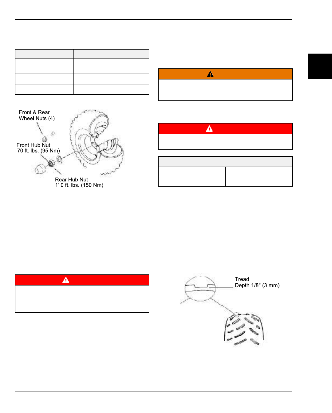
FINAL DRIVE / WHEEL AND TIRE
MAINTENANCE
WHEEL AND HUB TORQUE TABLE
ITEM SPECIFICATION
Steel Wheels Lug
Nuts
Front Hub Nut
Rear Hub Nut
35 ft-lb (47 Nm)
70 ft-lb (95 Nm)
110 ft-lb (150 Nm)
WHEEL REMOVAL
1. Place vehicle on a level surface.
2. Turn key off and set parking brake.
3. Block front and rear edge of tires on the side
opposite the wheels to be removed.
4. Loosen wheel nuts slightly.
5. Elevate side of vehicle by placing a jack or lift under
the frame. Place blocks under frame for additional
safety.
3. Remove safety supports and lower the jack.
4. Tighten wheel nuts (or lug nuts) to proper torque
listed in the Wheel and Hub torque table on Wheel
and Hub Torque Table, page 2.7.
2
CAUTION
If wheels are improperly installed it could affect vehicle
handling and tire wear. On vehicles with tapered lug
nuts, be sure tapered end of nut faces the wheel.
TIRE PRESSURE
WARNING
Maintain proper tire pressure. Refer to the warning tire
pressure decal applied to the vehicle.
TIRE PRESSURE INSPECTION (COLD)
Front Rear
20 psi (138 kPa) 20 psi (138 kPa)
TIRE INSPECTION
• Improper tire inflation may affect vehicle
maneuverability.
• When replacing a tire always use original equipment
size and type.
• The use of non-standard size or type tires may affect
vehicle handling.
Tire Tread Depth
Always replace tires when tread depth is worn to 1/8" (3
mm) or less.
WARNING
Care should be taken to be sure the vehicle is securely
supported and blocked to prevent movement when
elevated. Failure to follow the safety precautions could
6. Remove wheel nuts and washers (or lug nuts) and
remove wheel.
result in serious injury or death.
WHEEL INSTALLATION
1. Place wheel on hub. Be sure valve stem is outward
and rotation arrows on tire point in forward rotation.
2. Install washers and wheel nuts (or lug nuts with
tapered end toward wheel) and tighten lightly by
hand until wheel is centered and firmly supported.
9926595 R01 - 2015-2016 RANGER EV Service Manual
© Copyright Polaris Industries Inc.
2.7
Page 54

MAINTENANCE
WARNING
Operating a RANGER EV with worn tires will increase
the possibility of the vehicle skidding easily with
Always replace tires when the tread depth measures 1/
possible loss of control.
Worn tires can cause an accident.
8" (.3 cm) or less.
CV SHAFT BOOT INSPECTION
Inspect inner and outer CV joint boots on front and rear
drive axles for damage, tears, wear, or leaking grease.
Replace if worn, damaged, or leaking. See Chapter 7 for
boot replacement.
2.8
9926595 R01 - 2015-2016 RANGER EV Service Manual
© Copyright Polaris Industries Inc.
Page 55

GEARCASE MAINTENANCE
MAINTENANCE
FRONT GEARCASE LUBRICATION
Level Inspection
1. Position vehicle on a level surface.
2. Inspect vent hose routing and check it for kinks or
obstructions. The end of the hose should be under
the frame rail and point downward.
3. Remove fill plug (A). Fluid level should be even with
bottom of threads.
5. Reinstall fill plug and torque to specification.
TORQUE
Fill Plug:
10 ft-lb (14 Nm)
Front Gearcase Fluid Change:
6. Remove fill plug (C).
7. Place a drain pan under front gearcase area.
8. Remove drain plug (D). Drain fluid completely.
2
4. If fluid level is not even with the bottom threads, add
Polaris Demand Drive Plus as needed. Do not
overfill.
9926595 R01 - 2015-2016 RANGER EV Service Manual
© Copyright Polaris Industries Inc.
9. Clean drain plug magnetic surface.
10. Install drain plug with a new O-ring and torque to
specification.
11. Add recommended amount of fluid through fill hole
until level is even with bottom of fill hole threads (see
Level Inspection).
FLUID CAPACITY
Recommended Front Gearcase Fluid:
Demand Drive
(PN 2877922) (Quart)
6.1 oz. (180 ml)
12. Install fill plug with a new O-ring and torque to
specification.
TORQUE
Drain Plug:
10 ft-lb (14 Nm)
13. Check for leaks. Dispose of used fluid properly.
2.9
Page 56

MAINTENANCE
TRANSAXLE (REAR GEARCASE)
LUBRICANT
Level Inspection
1. Position vehicle on a level surface.
2. Inspect vent hose routing and check it for kinks or
obstructions. The end of the hose should be inside
the frame rail and point downward.
3. Remove fill plug (A) and check lubricant level.
4. If lubricant level is not even with the bottom of fill hole
threads (B), add ATV Angle Drive Fluid as needed.
Do not overfill.
2.10
5. Reinstall fill plug and torque to specification.
TORQUE
Fill Plug / Drain Plug:
14 ft-lb (19 Nm)
Transaxle Lubricant Change
1. Place a drain pan under transaxle drain plug area.
2. Place towels beneath fill plug and remove fill plug.
9926595 R01 - 2015-2016 RANGER EV Service Manual
© Copyright Polaris Industries Inc.
Page 57

3. Remove drain plug (C). Drain lubricant completely.
4. Clean drain plug magnetic surface. Reinstall drain
plug with a new O-ring and torque to specification.
TORQUE
Drain Plug & Fill Plug:
14 ft-lb (19 Nm)
MAINTENANCE
2
5. Add approximately 17-18 fluid ounces (500-550ml) of
lubricant through fill plug hole. Continue to add
lubricant to bring level to bottom of fill plug hole
threads. Do not overfill.
FLUID CAPACITY
Recommended Transaxle Lubricant:
Angle Drive Fluid
(PN 2876160 - Quart)
Capacity:
20.3 oz. (600 ml)
6. Reinstall fill plug with a new O-ring and torque to
specification above.
7. Check for leaks. Dispose of used lubricant properly.
9926595 R01 - 2015-2016 RANGER EV Service Manual
© Copyright Polaris Industries Inc.
2.11
Page 58

MAINTENANCE
STEERING
STEERING
Check steering components for loose fasteners, worn tie
rod ends, and damage. Check to be sure cotter pins are
in place on lower ball joints and steering tie rod ends.
Replace any worn or damaged steering components.
Steering should move freely through entire range of
travel without binding. Check routing of all cables, hoses,
and wiring to be sure the steering mechanism is not
restricted or limited.
NOTE
Whenever steering components are replaced, check
front end alignment.
WARNING
Due to the critical nature of the procedures outlined in
this section, Polaris recommends steering component
repair and adjustment be performed by an authorized
Polaris MSD-certified technician when replacing worn
or damaged steering parts.
Use only genuine Polaris replacement parts.
TIE ROD END / STEERING INSPECTION
• To check for play in the tie rod end, grasp the steering
tie rod, pull in all directions feeling for movement.
• If abnormal movement is detected, inspect hub and
wheel assembly to determine cause (loose wheel nuts
or loose front hub nut).
• Replace worn steering parts. Steering should move
freely through entire range of travel without binding.
• Elevate front end so front wheels are off the ground.
Check for any movement in front hub/wheel assembly
by grasping tire firmly at top and bottom first, and then
at front and rear. Try to move wheel and hub by
pushing inward and pulling outward.
2.12
WHEEL TOE ALIGNMENT INSPECTION
1. Place machine on a smooth level surface and set
steering wheel in a straight ahead position. Secure
steering wheel in this position.
9926595 R01 - 2015-2016 RANGER EV Service Manual
© Copyright Polaris Industries Inc.
Page 59

MAINTENANCE
2. Place a chalk mark on center line of front tires
approximately 10” (25.4 cm) from the floor or as
close to the hub/axle center line as possible.
NOTE
It is important the height of both marks be equally
positioned to get an accurate measurement.
3. Measure the distance between the marks and record
the measurement. Call this measurement “A”.
4. Rotate the tires 180° by moving the vehicle forward.
Position chalk marks facing rearward, even with the
hub/axle center line.
5. Again measure the distance between the marks and
record. Call this measurement “B”. Subtract
measurement “B” from measurement “A”. The
difference between measurements “A” and “B” is the
vehicle toe alignment. The recommended vehicle toe
tolerance is 1/8” to 1/4” (.3 to .6 cm) toe out. This
means the measurement at the front of the tire (A) is
1/8” to 1/4” (.3 to .6 cm) wider than the measurement
at the rear (B).
WARNING
Do not attempt to compensate for worn or damaged
steering parts by adjusting the tie rod ends. The threads
of the tie rod must engage the tie rod end by a minimum
of 3/4 inch (19 mm). If either tie rod is bent or damaged,
replace the steering gear box.
1. Turn steering wheel to straight ahead position.
2. Measure distance from centerline of vehicle to
centerline of each tire. Adjust tie rod end on side with
greatest amount of toe-out or toe-in.
3. Hold tie rod end (C) securely and loosen jam nut (D).
DO NOT allow rod end to rotate to full stop or
damage could occur to the rod end.
2
MEASUREMENT
Wheel Toe-Out:
(A) - (B) = 1/8 - 1/4" (.3 to .6 cm)
TOE ADJUSTMENT
If toe alignment is incorrect, adjust as follows.
9926595 R01 - 2015-2016 RANGER EV Service Manual
© Copyright Polaris Industries Inc.
4. Remove cotter pin (E) from tie rod end bolt.
2.13
Page 60

MAINTENANCE
5. Remove tie rod end nut and bolt with washers (F).
6. Hold tie rod at (G) and rotate rod end 1/2 turn at a
time to shorten or lengthen the overall tie rod length.
Shorten the tie rod to increase the amount of toe-out.
Lengthen the rod to decrease the amount of toe-out).
7. Temporarily install the tie rod on strut with washers,
bolt and nut. Tighten nut by hand so rod end is
securely supported and parallel with the mounting
surface on strut.
8. Verify steering wheel is centered and re-check
alignment.
9. Repeat above steps as required until proper
alignment is achieved, then assemble the tie rod to
strut with washers, bolt and nut.
10. Torque nut to specification and install a NEW cotter
pin.
11. HOLD tie rod end parallel with mounting surface.
Torque jam nut to specification. Check to be sure rod
end rotates freely.
TORQUE
Tie Rod Jam Nut:
14 ft-lb (19 Nm)
2.14
TORQUE
Tie Rod End Nut Torque:
40 ft-lb (54 Nm)
9926595 R01 - 2015-2016 RANGER EV Service Manual
© Copyright Polaris Industries Inc.
Page 61

SUSPENSION
MAINTENANCE
SUSPENSION INSPECTION
1. Compress and release front and rear suspension.
Damping should be smooth and consistent
throughout travel range.
2. Inspect each rear shock and front strut for oil
leakage.
3. Check all suspension components for wear or
damage.
4. Check all fasteners to be sure they are tight and all
cotter pins are installed where applicable. If any
fasteners are loose, refer to Chapter 4, Body,
Steering and Suspension for fastener torque values.
SUSPENSION PIVOT POINT LUBRICATION
• Both the front and rear suspension A-arms are
equipped with grease fittings at the pivot points. See
the maintenance chart for service intervals or grease
as needed.
STABILIZER BAR PIVOT LUBRICATION
Grease stabilizer bar pivots (A) with a grease gun until
old grease is purged from the joint and new grease
appears. Inspect link isolators (B) for cracks.
2
REAR SHOCK SPRING PRE-LOAD
ADJUSTMENT
The rear shock absorber springs are pre-load adjustable.
Use Spanner Wrench to rotate adjuster cam to increase
or decrease spring pre-load. Always adjust both left and
right sides equally.
9926595 R01 - 2015-2016 RANGER EV Service Manual
© Copyright Polaris Industries Inc.
Shock Spanner Wrench:
2871095
2.15
Page 62

MAINTENANCE
BRAKE SYSTEM
BRAKE FLUID INSPECTION
1. Position the vehicle on a level surface.
2. View the brake fluid level in the reservoir. The level
should be between the MAX and MIN level lines.
3. Clean the area around the fill cap. Remove cap and
add DOT 4 brake fluid if necessary.
4. Install reservoir cap.
5. Apply brake pedal forcefully for a few seconds and
check for fluid leakage around the master cylinder
fittings and the brake caliper fittings.
2. Inspect brake pad friction material thickness. Pads
should be changed when friction material is worn to
.040” (1 mm).
3. Visually inspect surface condition of brake discs. If
wear is evident, measure thickness of disc at 4
locations 90 degrees apart (A), and in 2 spots within
the brake pad contact area (B).
4. Disc(s) should be replaced if severely grooved, worn,
warped, or if disc thickness at any measurement
point is less than specified service limit (see Chapter
9 for specifications).
BRAKE HOSE AND FITTING INSPECTION
Check brake system hoses and fittings for cracks,
deterioration, abrasion, and leaks. Tighten any loose
fittings and replace any worn or damaged parts. Be sure
lines are secured away from moving parts or sharp
edges. Refer to Chapter 7 (Brakes) for torque values and
repair procedures.
BRAKE PAD / DISC INSPECTION
1. Check brake pads for wear, damage, or looseness.
2.16
9926595 R01 - 2015-2016 RANGER EV Service Manual
© Copyright Polaris Industries Inc.
Page 63

MAINTENANCE
PARKING BRAKE ADJUSTMENT
When the park brake is set and the park brake indicator
is illuminated, motor speed is limited. If the accelerator is
applied, this limiting feature prevents operation, which
protects the park brake pads from excessive wear.
NOTE
This feature will not operate properly if the park brake
connector or switch (under the hood) malfunctions or
becomes disconnected, or if the switch has moved.
Refer to Chapter 8 (Electrical) for diagnostics.
1. Pull back on the park brake lever.
3. If adjustment is required, return lever to the forward
position to release the brake. Adjust cable position in
the mounting bracket
described in Steps 4-6.
4. Using two open-end wrenches, loosen outer jam nut
and inner jam nute.
w
5. Adjust cable outward to tighten brake.
6. Tighten both jam nuts securely against bracket.
on the transaxle as
q
2
2. After 2 to 3 clicks the “BRAKE” light should illuminate
on the indicator panel and the wheels of the vehicle
should not rotate when turning by hand. After 8 full
clicks of lever travel, the vehicle should not roll while
parked.
9926595 R01 - 2015-2016 RANGER EV Service Manual
© Copyright Polaris Industries Inc.
7. Inspect park brake adjustment as described in Steps
1 and 2.
8. Repeat Step 4-6 until the proper adjustment is
obtained for the parking brake.
2.17
Page 64

MAINTENANCE
PARKING BRAKE PAD INSPECTION
Measure the thickness of the rear caliper parking brake
pads as described below. Refer to Brakes Chapter for
pad replacement procedure.
2.18
9926595 R01 - 2015-2016 RANGER EV Service Manual
© Copyright Polaris Industries Inc.
Page 65

ELECTRICAL SYSTEM
BATTERY MAINTENANCE
Refer to Chapter 1 GENERAL / BATTERY for all battery
information.
MAINTENANCE
BATTERY INFORMATION
Refer to Index to Battery Information, page 1.17
2
9926595 R01 - 2015-2016 RANGER EV Service Manual
© Copyright Polaris Industries Inc.
2.19
Page 66

MAINTENANCE
NOTES
2.20
9926595 R01 - 2015-2016 RANGER EV Service Manual
© Copyright Polaris Industries Inc.
Page 67

DRIVE MOTOR
CHAPTER 3
DRIVE MOTOR
SPECIAL TOOLS .. . . . . . . . . . . . . . . . . . . . . . . . . . . . . . . . . . . . . . . . . . . . . . . . . . . . . . . . . . . . . . . . . . . . . . . . . . . . . . . . . . . . . . . . 3.2
SPECIAL TOOLS . . . . . . . . . . . . . . . . . . . . . . . . . . . . . . . . . . . . . . . . . . . . . . . . . . . . . . . . . . . . . . . . . . . . . . . . . . . . . . . . . . . . . . 3.2
SAFETY INFORMATION. . . . . . . . . . . . . . . . . . . . . . . . . . . . . . . . . . . . . . . . . . . . . . . . . . . . . . . . . . . . . . . . . . . . . . . . . . . . . . . . . 3.3
BATTERY HANDLING WARNINGS . . . . . . . . . . . . . . . . . . . . . . . . . . . . . . . . . . . . . . . . . . . . . . . . . . . . . . . . . . . . . . . . . . . . 3.3
SERVICE PRECAUTIONS . . . . . . . . . . . . . . . . . . . . . . . . . . . . . . . . . . . . . . . . . . . . . . . . . . . . . . . . . . . . . . . . . . . . . . . . . . . . . 3.3
SPECIFICATIONS. . . . . . . . . . . . . . . . . . . . . . . . . . . . . . . . . . . . . . . . . . . . . . . . . . . . . . . . . . . . . . . . . . . . . . . . . . . . . . . . . . . . . . . . 3.4
TORQUE SPECIFICATIONS. . . . . . . . . . . . . . . . . . . . . . . . . . . . . . . . . . . . . . . . . . . . . . . . . . . . . . . . . . . . . . . . . . . . . . . . . . . 3.4
MOTOR SERVICE DATA .. . . . . . . . . . . . . . . . . . . . . . . . . . . . . . . . . . . . . . . . . . . . . . . . . . . . . . . . . . . . . . . . . . . . . . . . . . . . . 3.4
DRIVE MOTOR . . . . . . . . . . . . . . . . . . . . . . . . . . . . . . . . . . . . . . . . . . . . . . . . . . . . . . . . . . . . . . . . . . . . . . . . . . . . . . . . . . . . . . . . . . . 3.5
DRIVE MOTOR ASSEMBLY VIEW . . . . . . . . . . . . . . . . . . . . . . . . . . . . . . . . . . . . . . . . . . . . . . . . . . . . . . . . . . . . . . . . . . . . . 3.5
DRIVE MOTOR SERVICE .. . . . . . . . . . . . . . . . . . . . . . . . . . . . . . . . . . . . . . . . . . . . . . . . . . . . . . . . . . . . . . . . . . . . . . . . . . . . . . 3.6
DRIVE MOTOR REMOVAL . . . . . . . . . . . . . . . . . . . . . . . . . . . . . . . . . . . . . . . . . . . . . . . . . . . . . . . . . . . . . . . . . . . . . . . . . . . . 3.6
DRIVE MOTOR INSTALLATION .. . . . . . . . . . . . . . . . . . . . . . . . . . . . . . . . . . . . . . . . . . . . . . . . . . . . . . . . . . . . . . . . . . . . . . 3.7
DRIVE MOTOR DISASSEMBLY . . . . . . . . . . . . . . . . . . . . . . . . . . . . . . . . . . . . . . . . . . . . . . . . . . . . . . . . . . . . . . . . . . . . . . . 3.8
ROTOR REMOVAL . . . . . . . . . . . . . . . . . . . . . . . . . . . . . . . . . . . . . . . . . . . . . . . . . . . . . . . . . . . . . . . . . . . . . . . . . . . . . . . . . . .3.10
BEARING REPLACEMENT . . . . . . . . . . . . . . . . . . . . . . . . . . . . . . . . . . . . . . . . . . . . . . . . . . . . . . . . . . . . . . . . . . . . . . . . . . . 3.11
DRIVE MOTOR ASSEMBLY .. . . . . . . . . . . . . . . . . . . . . . . . . . . . . . . . . . . . . . . . . . . . . . . . . . . . . . . . . . . . . . . . . . . . . . . . .3.12
DRIVE MOTOR BENCH TESTS . . . . . . . . . . . . . . . . . . . . . . . . . . . . . . . . . . . . . . . . . . . . . . . . . . . . . . . . . . . . . . . . . . . . . . 3.13
3
9926595 R01 - 2015-2016 RANGER EV Service Manual
© Copyright Polaris Industries Inc.
3.1
Page 68

DRIVE MOTOR
SPECIAL TOOLS
SPECIAL TOOLS
PART NUMBER DESCRIPTION
Commercially Available
Commercially Available
Commercially Available
Commercially Available
Commercially Available
Bosch Automotive Service Solutions: Dealers may
order special tools through Polaris’ official tool supplier,
Bosch Automotive Service Solutions, by phone at 1-800345-2233 or on-line at http://polaris. service-solutions.
com/
Insulated Drive Ratchet
Insulated Extension 3 inch
Insulated Extension 6 inch
Insulated Socket 1/2 inch
Insulated Wrench Set
3.2
9926595 R01 - 2015-2016 RANGER EV Service Manual
© Copyright Polaris Industries Inc.
Page 69

SAFETY INFORMATION
BATTERY HANDLING WARNINGS
Before you begin work on the vehicle, review all battery
safety and handling precautions in chapter 1.
WARNING
Use insulated tools or insulate any tools used within the
battery area to prevent sparks or battery explosion
caused by shorting the battery terminals or wiring.
Remove any jewelry, rings. bracelets, etc.
SERVICE PRECAUTIONS
WARNING
The main power connector must be disconnected
before working on the electrical system or drive motor.
WARNING
Make sure the vehicle is properly immobilized before
beginning any maintenance or repair.
Always block the chassis securely and set the parking
brake before working under the vehicle.
DRIVE MOTOR
3
9926595 R01 - 2015-2016 RANGER EV Service Manual
© Copyright Polaris Industries Inc.
3.3
Page 70

DRIVE MOTOR
SPECIFICATIONS
TORQUE SPECIFICATIONS
ITEM
Terminal Block Nuts
(3 motor cables to motor)
Terminal Cover Screw
Motor Case Bolts
Motor Mounting Bolts (M6) 8 ft-lb (11 Nm)
Motor Mounting Bolt (M8) 17 ft-lb (23 Nm)
Motor Support Bracket to Motor 8 ft-lb (11 Nm)
Motor Support Bracket to Frame 17 ft-lb (23 Nm)
Speed Sensor Screw 62 in-lb (7 Nm)
TORQUE
11 ft-lb (15 Nm)
31 in-lb (4 Nm)
8 ft-lb (11 Nm)
MOTOR SERVICE DATA
DRIVE MOTOR COMPONENT SPECIFICATION
STATOR
TEMPERATURE
SENSOR
(Thermistor)
TEMPERATURE
SENSOR
(Thermistor)
Winding Resistance
Winding Resistance to Motor Case Infinite (O.L.)
Sensor Resistance
(Black Wire to White Wire in the white
harness)
Sensor Resistance
(Black Wire or White Wire to Motor Case
580 W (.580 K +/- 20% @ 68° F (20° C)
0.1-0.2 Ω +/- 20%
Infinite (O.L.)
3.4
9926595 R01 - 2015-2016 RANGER EV Service Manual
© Copyright Polaris Industries Inc.
Page 71

DRIVE MOTOR
DRIVE MOTOR ASSEMBLY VIEW
DRIVE MOTOR
3
Drive End Ring
q
Rotor
w
Stator,
e
Terminal Base
r
Group Terminal Board
t
11 ft-lb (15 Nm)
Group Plug,
y
Temperature Sensor
Temperature Sensor
u
Harness
Gear Wheel Sensor
i
Seal, Fitting
o
Seal, Plate
a
Cover Plate
s
Screw, Cover (QTY.4)
d
31 in-lb (4 Nm)
Connector, Speed
f
Sensor
Speed Sensor
g
Screw, Speed Sensor
h
62 in-lb (7 Nm)
Circlip
j
Ball Bearing
k
O-Ring
l
Circlip
1*
Bolt, Drive Motor
2)
8 ft-lb (11 Nm)
Threaded Plug
2!
-
9926595 R01 - 2015-2016 RANGER EV Service Manual
© Copyright Polaris Industries Inc.
3.5
Page 72

DRIVE MOTOR
DRIVE MOTOR SERVICE
DRIVE MOTOR REMOVAL
1. Turn key switch OFF.
2. Set parking brake.
3. Set direction selector switch to NEUTRAL.
4. Remove seat, storage trays, and cargo box Seat /
Storage Trays, page .
5. Disconnect main power connector. See: Main Power
Connector, page
CAUTION
Failure to disconnect the main power connector can
permanently damage electrical components.
6. Be sure cable identification tags U, V, and W are in
place on cables (at the motor end) so they can be
properly connected upon installation. If cables tags
are missing, mark cables location before removal.
8. Push tabwto separate wire harness connector at
drive motor.
9. Remove the three upper motor mount boltse.
7. Remove three cables from drive motor terminal
block.
3.6
10. Remove lower motor mount boltr.
9926595 R01 - 2015-2016 RANGER EV Service Manual
© Copyright Polaris Industries Inc.
Page 73
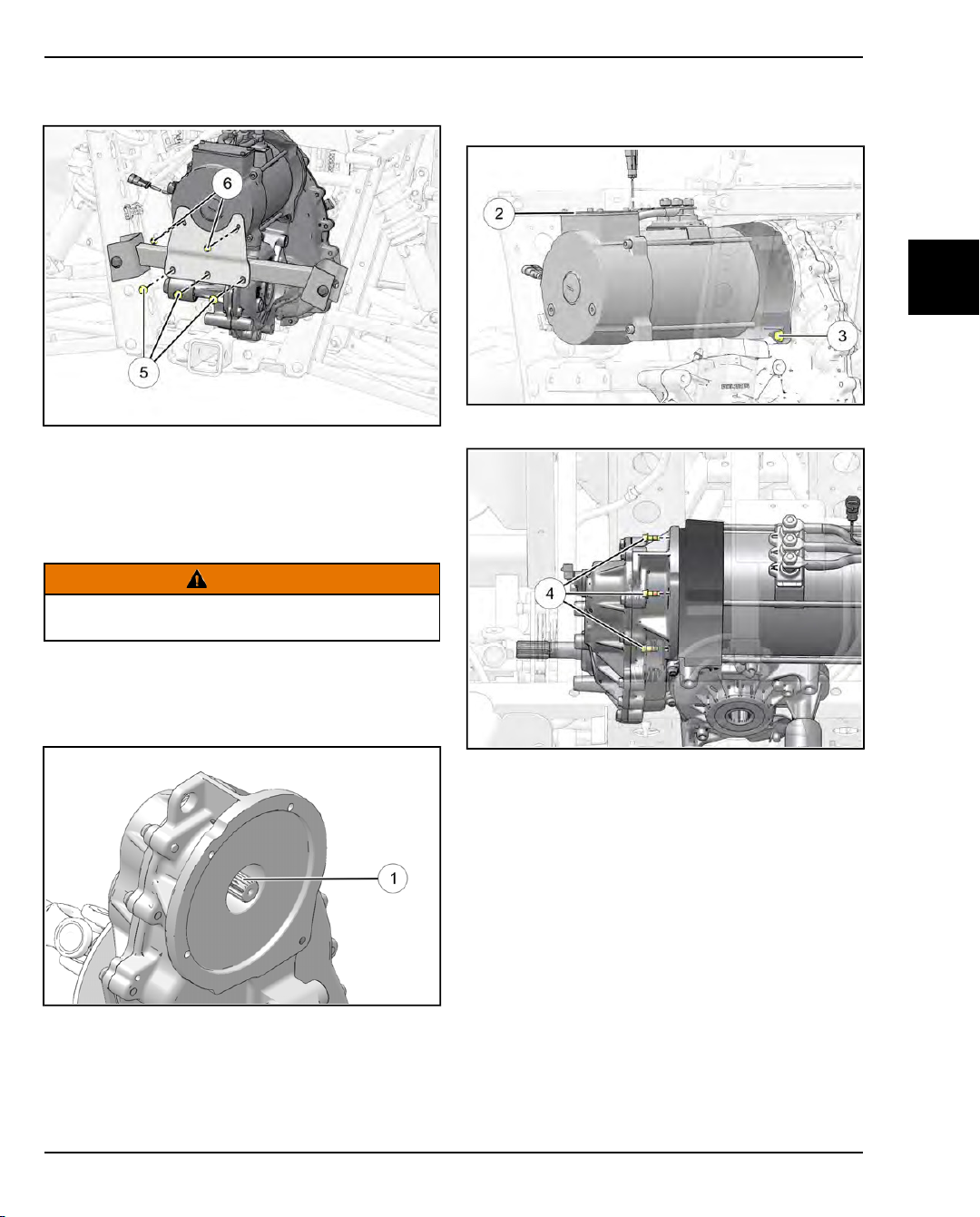
DRIVE MOTOR
11. Remove support bracket lower fastenerst, upper
fastenersyand bracket.
12. Protect cosmetic surfaces with suitable towel. Lift
back of motor slightly with a pry bar then alternately
push down until motor is loose.
13. Slide motor off transaxle shaft splines and out the
back. For drive motor disassembly refer toDrive
Motor Disassembly, page .
CAUTION
The drive motor weighs over 80 pounds (36.3 kg). Have
an assistant help remove the motor or use a suitable lift.
3. Orient motor as shown so the terminal cover
parallel to the ground and install the lower motor
mount boltefinger tight.
4. Loosely install the three upper motor mount boltsr.
w
is
3
DRIVE MOTOR INSTALLATION
1. Apply a light film of anti-seize compound to transaxle
shaft splines
2. With the aid of an assistant or a mechanical lift or
hoist, lift the motor into position near the transaxle
shaft. Align splines of transaxle shaft with motor
shaft and slide motor toward transaxle housing until
seated.
9926595 R01 - 2015-2016 RANGER EV Service Manual
© Copyright Polaris Industries Inc.
q
.
3.7
Page 74

DRIVE MOTOR
5. Loosely install rear support bracket with upper and
lower fastenerstandy. Do not tighten support
bracket bolts at this time.
6. Tighten motor mount bolts evenly by hand until motor
is drawn tight against transaxle.
7. Torque lower motor mount bolt to specification first,
then torque the upper motor mount bolts.
TORQUE
Motor Mount Bolt (M8):
17 ft-lb (23 Nm)
12. Connect cable marked “W” and install washer and
nut.
13. Hold cable centered in terminal cover and torque
each nut to specification.
TORQUE
Motor Cable Nuts:
11 ft-lb (15 Nm)
14. Connect sensor wire harness to drive motor
careful to align connector halves and avoid pin
damage.
u
. Be
TORQUE
Motor Mount Bolts (M6):
8 ft-lb (11 Nm)
8. Tighten three upper (M6) rear support bracket
screws evenly by hand until all are hand tight, then
torque all three bolts to specification.
TORQUE
Rear Support Bracket - Upper Bolts:
8 ft-lb (11 Nm)
9. Tighten three lower (M8) rear support bracket bolts
evenly by hand until all are hand tight. Torque bolts
to specification.
TORQUE
Rear Support Bracket - Lower Bolts:
17 ft-lb (23 Nm)
10. Connect rear-most drive motor cable (marked “U”) to
terminal block and install washer and nut.
11. Connect cable marked “V” and install washer and
nut.
3.8
15. Check all wiring and fasteners for proper assembly.
16. Re-connect main power connector.
17. Install storage trays, seat, and cargo box.
18. Test drive vehicle.
DRIVE MOTOR DISASSEMBLY
Also refer to Drive Motor Assembly View, page 3.5.
1. Mark casing and drive end housing for reference
during reassembly.
9926595 R01 - 2015-2016 RANGER EV Service Manual
© Copyright Polaris Industries Inc.
Page 75

DRIVE MOTOR
2. Remove speed sensor screwqand speed sensor.
3. Remove the three nutswsecuring terminal leads to
the terminal block.
4. Remove the cover plate screwse, cover plate and
gasket.
5. Lift terminal leads and remove guide blockr.
6. Remove motor case bolts
blocky.
and remove terminal
t
3
9926595 R01 - 2015-2016 RANGER EV Service Manual
© Copyright Polaris Industries Inc.
3.9
Page 76

DRIVE MOTOR
7. Tap housing lightly to separate the rear housing /
rotor assembly from the stator assembly.
8. Carefully pull wires through cover and slide rotor and
housing out of stator.
2. Remove circlip
3. Support housing. Select a suitable arbor which is
slightly smaller than the rotor shaft. Carefully press
rotor from bearing. Be prepared to catch rotor.
from end of rotor.
w
9. For bench tests see Drive Motor Bench Tests, page
3.13.
ROTOR REMOVAL
1. Remove threaded capqfrom housing.
3.10
9926595 R01 - 2015-2016 RANGER EV Service Manual
© Copyright Polaris Industries Inc.
Page 77

DRIVE MOTOR
4. Inspect rotor for damage.
BEARING REPLACEMENT
BEARING MUST BE REPLACED IF REMOVED
1. Remove internal snap-ringq.
2. Support cover as shown. Tap or press bearing from
cover.
3
3. Clean bearing bore and retaining ring groove.
Remove any burrs.
4. Install a new O-ring and lubricate O-ring and bore
with a light film of grease.
9926595 R01 - 2015-2016 RANGER EV Service Manual
© Copyright Polaris Industries Inc.
5. Set new bearing in freezer on wax paper or plastic
wrap for 15-30 minutes. When bearing is cool, warm
cover on a thermostatically controlled hot plate to
150° F (65° C). Do not exceed 150° F or bearing may
be damaged.
6. Press bearing past O-ring and into bore by hand (if
possible).
7. If bearing cannot be installed by hand, select a
suitable arbor that will press on the outer race of the
bearing. The bearing should install with minimal
press effort.
8. Install the internal snap-ring. Be sure it is fully seated
in the groove.
3.11
Page 78

DRIVE MOTOR
DRIVE MOTOR ASSEMBLY
1. Press rotor into bearing until seated and circlip
and threaded capwcan be installed.
2. Slide the rotor into the motor housing feeding the
three terminal leads
motor end capr.
through the access port in the
e
q
4. Install drive end housing with mounting boss
positioned as shown.
5. Install motor case bolts
specification.
and torque to
u
3. With the motor end cap seated, slide the terminal
lead guidetinto position, fit the terminal block
onto the motor.
y
3.12
TORQUE
Motor Case Bolts:
8 ft-lb (11 Nm)
6. Install motor end cap access cover and gasket.
Torque to specification.
TORQUE
Access Cover Screws:
31 in-lb (4 Nm)
9926595 R01 - 2015-2016 RANGER EV Service Manual
© Copyright Polaris Industries Inc.
Page 79

DRIVE MOTOR
7. Install nuts on wire terminal block to secure leads to
the block and torque to specification.
TORQUE
Terminal Block Nuts:
11 ft-lb (15 Nm)
8. Install drive motor (Drive Motor Installation, page
3.7).
DRIVE MOTOR BENCH TESTS
The main components of the drive motor can be tested
with an Ohmmeter. In addition to the bench tests outlined
here, look for physical damage, corrosion, and
discoloration from overheating. These tests can also be
performed with the motor installed on the vehicle (see
Chapter 8, Electrical).
Thermistor Test
1. Connect an Ohmmeter across the two wires leading
from the stator (white harness). Compare reading to
specification.
2. Connect one meter lead to either of the two wires
and the other to the motor case. There should be no
continuity to the case (Infinite or O.L.).
3. Connect one lead of an Ohmmeter to each stator
lead and the other to the stator case. There should
be no continuity to the case on any of the three
leads.
3
STATOR WINDINGS TO GROUND
Ω (OL)
TEMPERATURE SENSOR RESISTANCE
580 Ω ± 10% @ 68° F (20° C)
SENSOR WIRE(S) TO MOTOR CASE:
Ω (OL)
9926595 R01 - 2015-2016 RANGER EV Service Manual
© Copyright Polaris Industries Inc.
3.13
Page 80

DRIVE MOTOR
4. Connect one lead of an Ohmmeter to one stator lead
and the other Ohmmeter lead to each of the other
two. There should be good continuity (less than .5
Ohms) between each combination of two stator
windings. NOTE: If reading is greater than .5 Ohms,
be sure to subtract meter lead resistance from the
measured resistance (connect leads together and
record resistance displayed on meter. Subtract this
value from stator winding resistance measurement.
OHMMETER
LEAD 1
OHMMETER
LEAD 2
RESISTANCE
(+/- 20%)
Stator Phase 1 Stator Phase 2 0.1 - 0.2 Ω
Stator Phase 1 Stator Phase 3 0.1 - 0.2 Ω
Stator Phase 2 Stator Phase 3 0.1 - 0.2 Ω
3.14
9926595 R01 - 2015-2016 RANGER EV Service Manual
© Copyright Polaris Industries Inc.
Page 81

BODY / STEERING / SUSPENSION
CHAPTER 4
BODY / STEERING / SUSPENSION
GENERAL SPECIFICATIONS ... . . . . . . . . . . . . . . . . . . . . . . . . . . . . . . . . . . . . . . . . . . . . . . . . . . . . . . . . . . . . . . . . . . . . . . . . 4.2
TORQUE SPECIFICATIONS. . . . . . . . . . . . . . . . . . . . . . . . . . . . . . . . . . . . . . . . . . . . . . . . . . . . . . . . . . . . . . . . . . . . . . . . . . . 4.2
SPECIAL TOOLS . . . . . . . . . . . . . . . . . . . . . . . . . . . . . . . . . . . . . . . . . . . . . . . . . . . . . . . . . . . . . . . . . . . . . . . . . . . . . . . . . . . . . . 4.2
COMPONENT LOCATIONS . . . . . . . . . . . . . . . . . . . . . . . . . . . . . . . . . . . . . . . . . . . . . . . . . . . . . . . . . . . . . . . . . . . . . . . . . . . . . 4.3
RIGHT SIDE VIEW .. . . . . . . . . . . . . . . . . . . . . . . . . . . . . . . . . . . . . . . . . . . . . . . . . . . . . . . . . . . . . . . . . . . . . . . . . . . . . . . . . . . 4.3
FRONT VIEW . . . . . . . . . . . . . . . . . . . . . . . . . . . . . . . . . . . . . . . . . . . . . . . . . . . . . . . . . . . . . . . . . . . . . . . . . . . . . . . . . . . . . . . . . 4.3
REAR VIEW . . . . . . . . . . . . . . . . . . . . . . . . . . . . . . . . . . . . . . . . . . . . . . . . . . . . . . . . . . . . . . . . . . . . . . . . . . . . . . . . . . . . . . . . . . . 4.3
EXPLODED VIEWS . . . . . . . . . . . . . . . . . . . . . . . . . . . . . . . . . . . . . . . . . . . . . . . . . . . . . . . . . . . . . . . . . . . . . . . . . . . . . . . . . . . . . . 4.4
CHASSIS / MAIN FRAME / BUMPER . . . . . . . . . . . . . . . . . . . . . . . . . . . . . . . . . . . . . . . . . . . . . . . . . . . . . . . . . . . . . . . . . . 4.4
DASH SWITCHES AND INSTRUMENTS . . . . . . . . . . . . . . . . . . . . . . . . . . . . . . . . . . . . . . . . . . . . . . . . . . . . . . . . . . . . . . . 4.5
DASH MOUNTING . . . . . . . . . . . . . . . . . . . . . . . . . . . . . . . . . . . . . . . . . . . . . . . . . . . . . . . . . . . . . . . . . . . . . . . . . . . . . . . . . . . . 4.6
HOOD / FRONT FASCIA / MIRRORS .. . . . . . . . . . . . . . . . . . . . . . . . . . . . . . . . . . . . . . . . . . . . . . . . . . . . . . . . . . . . . . . . . 4.7
SEAT MOUNTING / SEAT BELTS . . . . . . . . . . . . . . . . . . . . . . . . . . . . . . . . . . . . . . . . . . . . . . . . . . . . . . . . . . . . . . . . . . . . . . 4.8
FLOOR / REAR FENDER / SIDE PANEL / CORNER PANEL . . . . . . . . . . . . . . . . . . . . . . . . . . . . . . . . . . . . . . . . . . . . 4.9
CARGO BOX / TAILGATE / CARGO BOX SUPPORT . . . . . . . . . . . . . . . . . . . . . . . . . . . . . . . . . . . . . . . . . . . . . . . . . .4.10
CAB FRAME EXPLODED VIEW . . . . . . . . . . . . . . . . . . . . . . . . . . . . . . . . . . . . . . . . . . . . . . . . . . . . . . . . . . . . . . . . . . . . . . 4.11
BODY COMPONENT REMOVAL. . . . . . . . . . . . . . . . . . . . . . . . . . . . . . . . . . . . . . . . . . . . . . . . . . . . . . . . . . . . . . . . . . . . . . .4.12
SEAT / STORAGE TRAYS . . . . . . . . . . . . . . . . . . . . . . . . . . . . . . . . . . . . . . . . . . . . . . . . . . . . . . . . . . . . . . . . . . . . . . . . . . . . 4.12
FRONT BUMPER / GRILL . . . . . . . . . . . . . . . . . . . . . . . . . . . . . . . . . . . . . . . . . . . . . . . . . . . . . . . . . . . . . . . . . . . . . . . . . . . .4.12
FOOT PADS / CORNER PANEL / SIDE PANEL. . . . . . . . . . . . . . . . . . . . . . . . . . . . . . . . . . . . . . . . . . . . . . . . . . . . . . . .4.12
CARGO BOX REMOVAL .. . . . . . . . . . . . . . . . . . . . . . . . . . . . . . . . . . . . . . . . . . . . . . . . . . . . . . . . . . . . . . . . . . . . . . . . . . . .4.12
CARGO BOX INSTALLATION. . . . . . . . . . . . . . . . . . . . . . . . . . . . . . . . . . . . . . . . . . . . . . . . . . . . . . . . . . . . . . . . . . . . . . . . .4.13
HOOD / DASH. . . . . . . . . . . . . . . . . . . . . . . . . . . . . . . . . . . . . . . . . . . . . . . . . . . . . . . . . . . . . . . . . . . . . . . . . . . . . . . . . . . . . . . .4.13
FLOOR... . . . . . . . . . . . . . . . . . . . . . . . . . . . . . . . . . . . . . . . . . . . . . . . . . . . . . . . . . . . . . . . . . . . . . . . . . . . . . . . . . . . . . . . . . . . . 4.13
STEERING. . . . . . . . . . . . . . . . . . . . . . . . . . . . . . . . . . . . . . . . . . . . . . . . . . . . . . . . . . . . . . . . . . . . . . . . . . . . . . . . . . . . . . . . . . . . . . .4.15
STEERING ASSEMBLY EXPLODED VIEW . . . . . . . . . . . . . . . . . . . . . . . . . . . . . . . . . . . . . . . . . . . . . . . . . . . . . . . . . . . 4.15
SUSPENSION . . . . . . . . . . . . . . . . . . . . . . . . . . . . . . . . . . . . . . . . . . . . . . . . . . . . . . . . . . . . . . . . . . . . . . . . . . . . . . . . . . . . . . . . . . . 4.16
FRONT A-ARM REMOVAL / INSTALLATION . . . . . . . . . . . . . . . . . . . . . . . . . . . . . . . . . . . . . . . . . . . . . . . . . . . . . . . . . .4.16
BALL JOINT REPLACEMENT . . . . . . . . . . . . . . . . . . . . . . . . . . . . . . . . . . . . . . . . . . . . . . . . . . . . . . . . . . . . . . . . . . . . . . . .4.16
FRONT STRUT CARTRIDGE REPLACEMENT . . . . . . . . . . . . . . . . . . . . . . . . . . . . . . . . . . . . . . . . . . . . . . . . . . . . . . .4.18
FRONT STRUT EXPLODED VIEW. . . . . . . . . . . . . . . . . . . . . . . . . . . . . . . . . . . . . . . . . . . . . . . . . . . . . . . . . . . . . . . . . . . .4.19
REAR A-ARM REMOVAL / REPLACEMENT . . . . . . . . . . . . . . . . . . . . . . . . . . . . . . . . . . . . . . . . . . . . . . . . . . . . . . . . . .4.20
REAR A-ARM INSTALLATION .. . . . . . . . . . . . . . . . . . . . . . . . . . . . . . . . . . . . . . . . . . . . . . . . . . . . . . . . . . . . . . . . . . . . . . .4.21
REAR A-ARM EXPLODED VIEW . . . . . . . . . . . . . . . . . . . . . . . . . . . . . . . . . . . . . . . . . . . . . . . . . . . . . . . . . . . . . . . . . . . . .4.22
REAR STABILIZER BAR REMOVAL / INSTALLATION . . . . . . . . . . . . . . . . . . . . . . . . . . . . . . . . . . . . . . . . . . . . . . . . .4.22
EXPLODED VIEW . . . . . . . . . . . . . . . . . . . . . . . . . . . . . . . . . . . . . . . . . . . . . . . . . . . . . . . . . . . . . . . . . . . . . . . . . . . . . . . . . . . .4.23
SHOCK REMOVAL / INSTALLATION.. . . . . . . . . . . . . . . . . . . . . . . . . . . . . . . . . . . . . . . . . . . . . . . . . . . . . . . . . . . . . . . . .4.23
SHOCK REPLACEMENT . . . . . . . . . . . . . . . . . . . . . . . . . . . . . . . . . . . . . . . . . . . . . . . . . . . . . . . . . . . . . . . . . . . . . . . . . . . . .4.24
SHOCKS EXPLODED VIEW. . . . . . . . . . . . . . . . . . . . . . . . . . . . . . . . . . . . . . . . . . . . . . . . . . . . . . . . . . . . . . . . . . . . . . . . . .4.24
DECAL REPLACEMENT . . . . . . . . . . . . . . . . . . . . . . . . . . . . . . . . . . . . . . . . . . . . . . . . . . . . . . . . . . . . . . . . . . . . . . . . . . . . . . . .4.24
DECAL REPLACEMENT. . . . . . . . . . . . . . . . . . . . . . . . . . . . . . . . . . . . . . . . . . . . . . . . . . . . . . . . . . . . . . . . . . . . . . . . . . . . . .4.25
4
9926595 R01 - 2015-2016 RANGER EV Service Manual
© Copyright Polaris Industries Inc.
4.1
Page 82

BODY / STEERING / SUSPENSION
GENERAL SPECIFICATIONS
TORQUE SPECIFICATIONS
NOTE
Refer to exploded views throughout this chapter for
torque specifications, component identification, and
SPECIAL TOOLS
PART NUMBER TOOL DESCRIPTION
2870872
2870623
2876389 Multi-Function Pliers
2870871 Strut and Ball Joint Tool Set
2871573
2871574
Dealers may order special tools through Polaris’ official
tool supplier, Bosch Automotive Service Solutions, by
phone at 1-800-345-2233 or on-line at http://polaris.
service-solutions.com/ Included in the tool kit, the multifunction pliers are designed to remove the plastic push
rivets used to fasten body components.
location of components.
Shock Spanner Wrench
Shock Spring Compressor Tool
Strut Spring Compressor (LH)
Strut Spring Compressor (RH)
4.2
9926595 R01 - 2015-2016 RANGER EV Service Manual
© Copyright Polaris Industries Inc.
Page 83

COMPONENT LOCATIONS
BODY / STEERING / SUSPENSION
RIGHT SIDE VIEW
FRONT VIEW
REAR VIEW
4
9926595 R01 - 2015-2016 RANGER EV Service Manual
© Copyright Polaris Industries Inc.
4.3
Page 84

BODY / STEERING / SUSPENSION
EXPLODED VIEWS
CHASSIS / MAIN FRAME / BUMPER
NUMBER PART DESCRIPTION
1 Battery Tray
2 Cab Support
3 Main Frame
4
5
6 Seat Base, Cab Support
7
8
9
10 Bolt - M8 x 1.25 x 20 (QTY.32) 8 ft-lbs (10.8 Nm)
11
12
Floor Support, Left
Floor Support, Right
Skid Plate
Screw - M8 x 1.25 x 55 (QTY.4) 22 ft-lbs (29.8 Nm)
Screw - 1/4 - 20 x 5/8 (QTY.13) 8 ft-lbs (10.8 Nm)
Nut - M8 x 1.25 (QTY.4) 22 ft-lbs (29.8 Nm)
Washer, Skid Plate (QTY.13)
-
-
-
-
-
-
-
-
TORQUE (IF APPLICABLE)
4.4
9926595 R01 - 2015-2016 RANGER EV Service Manual
© Copyright Polaris Industries Inc.
Page 85

DASH SWITCHES AND INSTRUMENTS
BODY / STEERING / SUSPENSION
4
NUMBER PART DESCRIPTION
1
2
3
4
5
6
7 AWD Switch
8 Drive Mode Switch
9
Hour Meter / Battery Discharge Indicator
Indicator Light Panel
Key Switch (OFF / ON)
Headlight Switch
Drive Direction Selector
Charge Status Indicator
12V Accessory Socket
9926595 R01 - 2015-2016 RANGER EV Service Manual
© Copyright Polaris Industries Inc.
4.5
Page 86

BODY / STEERING / SUSPENSION
DASH MOUNTING
NUMBER PART DESCRIPTION
1
2
Screw - M6 x 1.0 x 25 (QTY.2) 8 ft-lbs (10.8 Nm)
Rivet (QTY.11)
TORQUE
-
4.6
9926595 R01 - 2015-2016 RANGER EV Service Manual
© Copyright Polaris Industries Inc.
Page 87

HOOD / FRONT FASCIA / MIRRORS
BODY / STEERING / SUSPENSION
4
NUMBER PART DESCRIPTION
q
w
e
r
t
y
u
i
Hood
Front Fascia
Dash Panel
Glove Box Lid
Hood Strap
Hood Hinge Pins
Push Rivet
Hood Latch
9926595 R01 - 2015-2016 RANGER EV Service Manual
© Copyright Polaris Industries Inc.
4.7
Page 88

BODY / STEERING / SUSPENSION
SEAT MOUNTING / SEAT BELTS
NUMBER PART DESCRIPTION
q
w
e
r
t
y
u
i
o
Shoulder Anchor, Seat Belt
Buckle, Seat Belt Driver
Buckle, Seat Belt Passenger -
Seat, Back
Seat, Base
Washer - Seat Belt, Rubber
Screw, Seat Back (QTY.8) 24 in-lb (3 Nm)
Bolt, Seat Belt Buckle - M12 x 1.75 (QTY.4) -
Nut, Seat Belt Buckle (QTY.4) 40 ft-lb (52 Nm)
TORQUE (IF APPLICABLE)
-
-
-
-
-
4.8
9926595 R01 - 2015-2016 RANGER EV Service Manual
© Copyright Polaris Industries Inc.
Page 89

FLOOR / REAR FENDER / SIDE PANEL / CORNER PANEL
BODY / STEERING / SUSPENSION
4
NUMBER PART DESCRIPTION
q
w
e
r
t
y
Front Floor
Main Floor
Floor Cover
Cup Holder -
Push Rivet
Screw:
TORQUE (IF APPLICABLE)
-
-
-
-
5 ft-lb (7 Nm)
9926595 R01 - 2015-2016 RANGER EV Service Manual
© Copyright Polaris Industries Inc.
4.9
Page 90

BODY / STEERING / SUSPENSION
CARGO BOX / TAILGATE / CARGO BOX SUPPORT
NUMBER PART DESCRIPTION
q
w
e
r
t
y
u
i
o
a
s
d
f
Cargo Box -
Box Frame
Tailgate Inner Panel -
Tailgate Outer Panel -
Box Tilt Shock
Box Tilt Latch
Heat Shield
Tailgate Tube -
Tailgate Mount Bracket -
Bushing -
Tailgate Latch -
Screw
Screw
TORQUE (IF APPLICABLE)
-
-
-
-
8 ft-lb (11 Nm)
5 ft-lb (7 Nm)
4.10
9926595 R01 - 2015-2016 RANGER EV Service Manual
© Copyright Polaris Industries Inc.
Page 91

CAB FRAME EXPLODED VIEW
BODY / STEERING / SUSPENSION
4
NUMBER PART DESCRIPTION
q
w
e
r
t
y
u
i
o
a
s
d
f
g
h
Cab Frame, LH
Cab Frame, RH
Cab Frame, Lower / Rear
Cab Support, Rear -
Windshield Mount, Upper -
Grab Handle
Bolt - M8 x 1.25 x 20 (QTY.8) 18 ft-lb (24 Nm)
Bolt - M10 x 1.5 x 20 (QTY.6) 36 ft-lb (49 Nm)
Bolt - M8 x 1.25 x 20 (QTY.2) 18 ft-lb (24 Nm)
Screw - M10 x 1.25 x 30 (QTY.4) 36 ft-lb (49 Nm)
Screw - M6 x 1.0 x 25 (QTY.2) 8 ft-lb (11 Nm)
Screw - M10 x 1.5 x 75 (QTY.4) 36 ft-lb (49 Nm)
Screw - M10 x 1.5 x 30 (QTY.4) 36 ft-lb (49 Nm)
Nut - M10 x 1.5 (QTY.6) -
Nut - M10 x 1.25 (QTY.4) -
TORQUE (IF APPLICABLE)
-
-
-
-
9926595 R01 - 2015-2016 RANGER EV Service Manual
© Copyright Polaris Industries Inc.
4.11
Page 92

BODY / STEERING / SUSPENSION
BODY COMPONENT REMOVAL
SEAT / STORAGE TRAYS
1. Lift rear edge of seat to release the retainerq.
2. Rotate rear of seat upward until the front hinge
can be released from the retaining bracket.
w
FRONT BUMPER / GRILL
1. Unlatch the hood and disconnect the head lamp
harnesses. Remove the two pivot screws retaining
the hood and remove the hood from the bumper.
2. Remove the three bolts
the bumper.
from the lower portion of
w
FOOT PADS / CORNER PANEL / SIDE
PANEL
1. FRONT - Remove the lower T27 Torx-head screws
retaining the foot pads.
2. Remove the two push rivets retaining the front fender
and remove the fender from the vehicle.
3. Repeat this procedure to remove the other front
fender.
4. REAR - Remove the lower T27 Torx-head screws
retaining the foot pads.
5. Remove the three T27 Torx-head screws retaining
the rear panel.
6. Repeat this procedure to remove the other rear
fender.
3. Remove the two fastenersqfrom each side of the
upper portion of the bumper.
4. Carefully remove the bumper from the vehicle.
4.12
CARGO BOX REMOVAL
1. Remove the screwqthat secures the hinge pin to
the frame on both sides.
9926595 R01 - 2015-2016 RANGER EV Service Manual
© Copyright Polaris Industries Inc.
Page 93

BODY / STEERING / SUSPENSION
2. Lift the cargo box into the dump position.
3. Disconnect the rear wire harness attached to the tail
lights.
4. Remove the upper clip
shock to the cargo box.
and pineattaching the
w
CAUTION
Safely support the box during the remainder of the
removal process. The box is not as stable with the
shock removed.
4. Secure the box hinges with the hinge screws on both
sides.
5. With the hinges installed, attach the shock to the
cargo box by inserting the pin and clip.
6. Lower the box and secure the latch.
HOOD / DASH
1. Hood Removal - Unlatch the hood and disconnect
the head lamp harnesses. Remove the two clips and
pivot pins retaining the hood and remove the hood
from the bumper.
2. Dash Removal (continued) - Remove the three
Torx-head screws retaining the front of the dash to
the frame.
3. Open the glove box and remove the Torx-head screw
from the dash.
4
5. Remove the hinge pin from both sides.
CAUTION
Safely support the box during the remainder of the
removal process. The box is not as stable with the
hinge pins removed.
6. With both hinge pins removed, remove the box from
the frame. Two people may be needed to remove the
box from the frame.
CAUTION
Use caution when removing the box. It is recommended
to have two people carefully remove the box from the
frame.
CARGO BOX INSTALLATION
1. If the shock was replaced, install the lower portion of
the shock to the frame and secure it with the pin and
clip.
2. Place the cargo box onto the frame. Align the hinges
of the box with the bracket on the frame.
3. Install the box hinges on both sides.
4. Remove the Torx-head screw retaining the left
portion of the dash.
5. Remove the eight fasteners from each side of the
dash where it attaches to the front and rear fenders.
6. Remove the rubber boot from around shift lever.
7. Remove the five push rivets from under the dash
panel. Unhook all electrical components to allow the
panel to be completely removed.
8. Carefully remove the dash assembly from the
vehicle.
FLOOR
1. Remove the Foot pads.
2. Remove the rear fender push rivets.
3. Remove the seven Torx-head screws retaining the
center floor.
4. Remove the Torx-head screws retaining the front
floor cover.
9926595 R01 - 2015-2016 RANGER EV Service Manual
© Copyright Polaris Industries Inc.
4.13
Page 94

BODY / STEERING / SUSPENSION
5. Remove the Torx-head screws retaining the main
floor and remove the main floor from the vehicle.
6. Continue with ‘Hood / Dash Removal’ procedure.
7. Remove the accelerator and brake pedals for
adequate clearance to remove the front floor section.
4.14
9926595 R01 - 2015-2016 RANGER EV Service Manual
© Copyright Polaris Industries Inc.
Page 95

STEERING
STEERING ASSEMBLY EXPLODED VIEW
BODY / STEERING / SUSPENSION
4
9926595 R01 - 2015-2016 RANGER EV Service Manual
© Copyright Polaris Industries Inc.
4.15
Page 96

BODY / STEERING / SUSPENSION
SUSPENSION
FRONT A-ARM REMOVAL / INSTALLATION
1. Elevate and safely support vehicle with weight
removed from front wheel(s).
2. Remove cotter pin from ball joint stud and remove
nut.
3. Separate A-arm from ball joint using a tie rod fork.
4. Loosen two bolts on A-arm bushing by alternating
each about 1/3 of the way until A-arm can be
removed.
5. Inspect A-arm bushings and A-arm shafts. Replace if
worn. Discard hardware.
6. Insert A-arm bushings and A-arm shaft into A-arm.
7. Install CV joint shields.
8. Install A-arm assembly onto vehicle frame. Torque
new bolts to specification.
TORQUE
A-arm Bolts:
30 ft-lb (41 Nm)
WARNING
The locking features on the existing bolts were
destroyed during removal. DO NOT reuse old bolts.
Serious injury or death could result if fasteners come
loose during operation.
9. Attach A-arm to hub strut ball joint. Tighten ball joint
nut to specification. If cotter pin holes are not
aligned, tighten nut slightly to align.
TORQUE
Ball Joint Nut:
30 ft-lb (41 Nm)
10. Install a new cotter pin with open ends toward front
of vehicle. Bend both ends in opposite directions
around nut.
WARNING
Upon A-arm installation completion, test vehicle at low
speeds before putting into regular service.
BALL JOINT REPLACEMENT
1. Loosen front wheel nuts slightly.
4.16
9926595 R01 - 2015-2016 RANGER EV Service Manual
© Copyright Polaris Industries Inc.
Page 97

BODY / STEERING / SUSPENSION
2. Elevate and safely support machine under footrest/
frame area.
WARNING
Serious injury may result if machine tips or falls. Be
sure machine is secure before beginning this service
procedure.
3. Remove wheel nuts and wheels.
4. Remove cotter pin (A) from ball joint castlenut.
5. Remove castle nut (B) and separate A-arm (C) from
ball joint stud.
6. Remove screws (D) and ball joint retaining plate (E).
7. Using ball joint removal/installation tool kit, remove
ball joint (F) from strut housing.
Ball Joint Tool:
2870871
• Install puller guide (G) with extension cap (H).
• Apply grease to extension cap and threads of puller
bolt to ease removal.
• Thread bolt (K) with nut (J) onto ball joint stud as
shown.
• Apply heat to ease removal.
• Hold bolt (K) and turn nut (J) clockwise until ball joint is
removed from strut housing.
•
4
9926595 R01 - 2015-2016 RANGER EV Service Manual
© Copyright Polaris Industries Inc.
8. To install new ball joint:
• Remove extension cap and attach puller guide using
short bolts provided in the kit.
• Insert new ball joint (L) into driver (M).
• Slide ball joint / driver assembly into guide.
• Apply heat to ease installation.
• Drive new joint into strut housing until fully seated.
4.17
Page 98

BODY / STEERING / SUSPENSION
9. Apply Loctite® 242 (PN 2871949) to threads of
retaining plate screws or install new screws with preapplied locking agent. Torque screws to
specification.
TORQUE
Ball Joint Retaining Plate Screws:
8 ft-lb (11 Nm)
10. Install dust boot over ball joint stud.
11. Install A-arm on ball joint and torque castle nut to
specification.
TORQUE
Ball Joint Nut:
30 ft-lb (41 Nm)
12. Reinstall cotter pin with open ends toward rear of
machine.
FRONT STRUT CARTRIDGE
REPLACEMENT
Refer to Illustration in Chapter 5.
1. Hold strut rod and remove top nut.
2. Compress spring using strut spring compressor
tools.
Strut Spring Compressor Tools:
2871573 and 2871574
3. Remove upper strut pivot assembly.
4. Remove coil spring and collapse strut cartridge.
5. Remove two pinch bolts from strut casting.
6. Remove strut cartridge.
7. Install cartridge until bottomed in strut casting.
8. Install pinch bolts with wire clamp (s). Torque pinch
bolts to specification.
TORQUE
Strut Pinch Bolts:
17 ft-lb (23 Nm)
9. Reassemble spring and top pivot assembly. Be sure
all parts are installed properly and seated fully.
10. Torque strut rod nut to specification. Do not over
torque nut.
TORQUE
Strut Rod Nut:
15 ft-lbs (21 Nm)
4.18
9926595 R01 - 2015-2016 RANGER EV Service Manual
© Copyright Polaris Industries Inc.
Page 99

FRONT STRUT EXPLODED VIEW
BODY / STEERING / SUSPENSION
4
9926595 R01 - 2015-2016 RANGER EV Service Manual
© Copyright Polaris Industries Inc.
4.19
Page 100

BODY / STEERING / SUSPENSION
REAR A-ARM REMOVAL / REPLACEMENT
The following procedure details upper and lower A-arm
removal and replacement on one side of the vehicle.
Repeat the following steps to remove the A-arm (s) from
the opposite side.
NOTE
Refer to Rear A-arm Exploded View, page 4.22 for
reference during the procedure.
1. Elevate and safely support the rear of vehicle off the
ground and remove the rear wheel.
3. Remove the fastener attaching the upper A-arm to
the bearing carrier.
4. Remove the fasteners attaching the upper A-arm to
the frame and remove the upper A-arm from the
vehicle.
Upper A-arm Removal
2. Remove the fastener retaining the lower portion of
the shock and stabilizer linkage to the upper A-arm.
5. Examine A-arm and bearing carrier bushings and
pivot tubes (see “Exploded View”). Replace if worn.
Discard hardware.
WARNING
The locking agent on the existing bolts was destroyed
during removal. DO NOT reuse old hardware. Serious
injury or death could result if fasteners come loose
during operation.
6. If not replacing the A-arm, thoroughly clean the aarm and pivot tubes.
7. Insert new A-arm bushings and pivot tubes into the
new A-arm.
Lower A-arm Removal
4.20
9926595 R01 - 2015-2016 RANGER EV Service Manual
© Copyright Polaris Industries Inc.
 Loading...