

Page 1

Polaris® Booster Pump PB4-60
Replacement Kits
WARNING
FOR YOUR SAFETY - This product must be installed and serviced by a contractor who is licensed and
qualified in pool equipment by the jurisdiction in which the product will be installed where such state or
local requirements exist. In the event no such state or local requirement exists, the maintainer must be
a professional with sufficient experience in pool equipment installation and maintenance so that all of
the instructions in this manual can be followed exactly. Improper installation and/or operation can create
dangerous electrical hazards, which can cause high voltages to run through the electrical system. Before
installing this product, read and follow all warning notices and instructions that accompany this product.
Failure to follow warning notices and instructions may result in property damage, personal injury, or death.
Improper installation and/or operation will void the warranty.
These instructions are to be used with the following Installation/Replacement Kits:
P17 -- Softube® Quick Connect Installation Kit
P19 -- 6’ Flexible Reinforced Pump Hose Installation Kit
P21 -- Pump Quick Connect Retainer
P61 -- 60 Hz, 3/4 HP Motor
P133 -- Softube Quick Connect with Retainers
R0445500 -- PB4-60 Ceramic Seal and Spring Replacement Kit
R0536300 -- PB4-60 Volute Replacement Kit
R0536400 -- PB4-60 Impeller Replacement Kit
R0536600 -- PB4-60 Backplate O-Ring Replacement Kit
R0536700 -- PB4-60 Backplate Replacement Kit
R0536800 -- PB4-60 Motor Bolts and Washers Replacement Kit
R0536900 -- PB4-60 Bolts, Washers, and Nuts Replacement Kit
R0537100 -- PB4-60 Booster Pump Base Replacement Kit
WARNING
If the information in these instructions is not followed exactly, an electrical re or shock hazard may result causing
property damage, personal injury or death.
This document gives instructions for replacing
the Volute, Impeller, Backplate, Base, Ceramic Seal,
Hose, O-Rings and Hardware on the PB4-60 Booster
Pump. The instructions must be followed exactly. These
instructions were written with safety as the priority.
Not following this procedure or taking shortcuts may
result in personal injury. Read through the instructions
completely before starting the procedure.
Before starting the procedure, use the parts list at
the back of these instructions to identify the parts that
are in your kit. If any parts are missing from the kit
please call your local Zodiac distributor for assistance.
For technical assistance please contact our Technical
Support Department at 800.822.7933.
H0332800 Rev A
1. Replace the Volute, Backplate O-Ring
and Drain Plug
WARNING
While servicing the pump, switch off the circuit
breakers at the power source. Severe personal
injury or death may occur if the pump starts while
your hand is inside the pump.
1. Turn off the pump. Switch off the circuit breaker
to the pump motor. If you are not replacing the
motor, do not disconnect the electrical wiring.
NOTE If you are replacing the motor, Zodiac Pool
Systems, Inc. strongly recommends that a
qualied service technician or electrician
properly disconnect the electrical wiring at the
pump motor.
Page 2
Page 2
• Ceramic Face Seal
• Carbon Face/ Spring
2. Turn off any valves to prevent pool water from
reaching the pump. Drain the water from the pump
by removing the drain plug.
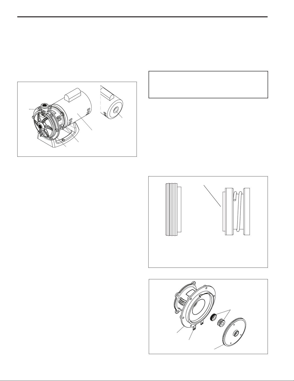
3. Using a 1/2” wrench, loosen the six (6) bolts
connecting the pump volute to the motor
backplate. Remove the bolts and washers and
either set aside to use in reassembly or use new
ones from the kit. See Figure 1.
Bolts
(Qty. 6)
Hex-Head
Motor Cover
Back
Plate
Volute
Figure 1. Remove the Volute
Motor
Body
4. Pull the volute from the backplate.
NOTE The impeller is a right-handed thread, therefore
turn the impeller counter-clockwise to unscrew.
4. Inspect the impeller for signs of rubbing and/or
damage and replace if necessary.
5. If you are replacing the mechanical seal do steps 6
through 10, if not, skip to step 11.
CAUTION
Do not damage the ceramic or carbon surfaces
of the seals. If surfaces are damaged, leaks will
occur.
6. Remove the carbon face seal half from the
impeller. Refer to Figure 2 and 3. This is a springloaded seal. Grasp the portion of the seal closest
to the impeller body and pull the seal off using a
twisting motion.
NOTE This is a two (2) part replacement process. The
mechanical seal must be replaced as a set.
7. Remove the four (4) 9/16” screws that secure the
backplate to the motor and remove the motor.
8. Place the backplate o-ring side down and force the
ceramic seal out using a screwdriver or drift pin.
NOTE At this point you have access to the inlet and
outlet of the impeller to remove any debris.
5. Remove the backplate o-ring and replace it with
the new o-ring making sure it is seated properly.
6. Install the new volute using six (6) bolts with six
(6) washers and six (6) nuts. Torque the bolts to
7±0.3 ft-lbs
7. If required, install the new drain plug. Torque to 8
to 10 in-lbs.
8. Turn on the lter pump and turn on the circuit
breaker to booster pump motor.
9. Once all the air has left the lter, close the
air release valve. (Follow the manufacturer’s
instructions for your lter.)
10. Turn on the booster pump and check the system
for proper normal operation.
2. Replace the Impeller and Mechanical
Ceramic/Spring Seal
1. To access the impeller and mechanical seal, follow
steps 1 though 4 of Section 1.
2. Remove the motor shaft cover on the back of the
motor by twisting the hex-head motor cover with
an adjustable wrench. See Figure 1. The motor
shaft will be exposed.
3. The impeller is connected to the motor shaft.
Hold the motor shaft with a ½” wrench while
unscrewing the impeller from the motor shaft with
your hand.
Carbon Seal Surface
• Backplate Seal
Figure 2. Replace the Mechanical Seal
Back Plate
Prongs
Impeller
Figure 3. Backplate, Impeller and Mechanical Seal
Location
Side of Seal
• Impeller Side of the
Mechanical Seal
Mechanical Seal
Page 3

Page 3
CAUTION
VERY IMPORTANT! Do not touch the face of the
seal. The oil from your hands will result in damage to
the seal.
9. Turn the backplate o-ring side up and insert the
new ceramic seal side into the backplate. Use
great care to press the seal in squarely with your
ngers. The ceramic is easily damaged and must
be pressed in using only your ngers or soft tools.
Do not use any lubricant other than water and soap
solution.
CAUTION
VERY IMPORTANT! Grasp the lower portion of
the seal (opposite the carbon face) when installing
the seal, or it will be damaged.
10. Press the new carbon face seal half (see Figure 2)
on the impeller using a twisting motion. Make sure
the carbon surface is facing toward the ceramic
ring in the backplate.
NOTE To assist assembly, only use water and soap
solution as a lubricant. Any other lubricant will
destroy the seal after a short period of time.
NOTE Exercise great care to keep the seal and mating
parts clean.
11. Install and tighten the screws lightly in a crossing
“X” pattern using a 9/16” wrench then tighten the
four (4) to draw the backplate to the motor body in
an even manner and torque in the same order to
14 ± 0.3 ft-lbs.
12. While holding the motor shaft with a ½” wrench,
thread the impeller onto the motor shaft.
Hand-tighten the impeller until it is secure. Do not
overtighten.
13. Replace the hex-head cover over the motor shaft
by inserting the cover tabs into the slots and
rotating the cover 90º clockwise.
14. Remove the backplate o-ring and replace it with
the new o-ring making sure it is seated properly.
15. Install the volute using six (6) bolts with six (6)
washers and six (6) nuts. Torque the bolts to 7±0.3
ft-lbs
16. If required, install the new drain plug. Torque to 8
to 10 in-lbs.
17. Turn on the lter pump and turn on the circuit
breaker to booster pump motor.
18. Once all the air has left the lter, close the air
release valve.
19. Turn on the booster pump and check the system
for normal operation.
3. Replace the Motor
WARNING
To ensure continued safety and reliable operation,
Zodiac Pool Systems, Inc. requires that you
replace the motor with a motor that has the
identical HP rating and service factor (Zodiac Pool
Systems, Inc. approved only). Using an improper
motor can create a safety hazard which could
cause serious injury.
WARNING
To avoid the risk of property damage, severe
personal injury, or death, turn off the pump and
switch off the circuit breaker to the pump motor
before beginning this procedure.
1. Have a qualied service technician or electrician
properly disconnect the electrical wiring at the
pump motor.
2. To disassemble the pump volute from the motor,
follow steps 1 through 4 in Section 2.
3. Remove the four (4) 9/16” screws and remove the
motor.
NOTE Before removing the backplate, note the
alignment of the backplate to the motor. Label is
facing upward.
4. If installing a new motor, remove the protective
plastic cap from the motor shaft. Place the motor
on the backplate. The label should be facing
upward. The starting capacitor on the motor should
be at the 12 o’clock position.
5. Replace the four (4) bolts and washers holding the
backplate to the motor.
6. To reassemble the pump after replacing the motor,
follow steps 10 through 16 of Section 2.
7. Have a qualied service technician or electrician
properly connect the electrical wiring at the pump
motor.
NOTE Zodiac Pool Systems, Inc. recommends that the
mechanical seals be replaced at the same time
the motor is replaced. See Section 2, for the
mechanical seal replacement instructions.
4. Replace the Pump Base
1. Remove the pump base by pressing the release
tabs on the base.
2. Install the new base by placing the backplate
prongs into the base slots to secure.
Page 4

Page 4
5. Install the Softube® Quick Disconnect,
Retainer and Hose
1. Slide the quick connect retainer ring over the
Hose
Softube quick connect threads. Install quick
connects onto pump discharge and supply ports.
See Figures 4 and 5.
Retainer Clip
Sleeve
2. Measure and cut reinforced hose ensuring cut is
clean, with no more than a 30º
off straight edge
.
Figure 5. Install the Retainer Clip
Avoid unnecessary loops or bends in the hose.
3. Push the hose onto the quick connect until it is
ush against the hose barb base. See Figure 4
Hose Barb
Retainer Clip
4. Holding the hose in place, pull and twist the
sleeve on the quick connect over the hose as far as
possible. Snap the clip into place. See Figure 5.
Hose
6. Parts List
Sleeve
Threads
Figure 4. Install the Hose onto the Quick
Disconnect
DESCRIPTION
6’ Flexible Reinforced Pump Hose 1 1 -- -- -- -- -- -- -- -- -- -- --
Softube Quick Disconnect 4 -- -- -- 4 -- -- -- -- -- -- -- --
Pump Quick Connect Retainer 4 -- 4 -- -- -- -- -- -- -- -- -- --
3/4 HP 60 Hz Motor -- -- -- 1 -- -- -- -- -- -- -- -- --
Volute -- -- -- -- -- -- 1 -- -- -- -- -- --
O-Ring -- -- -- -- -- -- 1 -- -- -- -- -- --
Drain Pump Seal -- -- -- -- -- -- 1 -- -- -- -- -- --
Drain Plug -- -- -- -- -- -- 1 -- -- -- -- -- --
Impeller Assembly -- -- -- -- -- 1 -- 1 -- -- -- -- --
Carbon Mechanical Seal -- -- -- -- -- -- -- -- -- 1 -- -- --
Ceramic Mechanical Seal -- -- -- -- -- -- -- -- -- 1 -- -- --
Backplate O-Ring -- -- -- -- -- -- -- -- 1 1 -- -- --
Backplate -- -- -- -- -- -- -- -- -- 1 -- -- --
Motor Bolt -- -- -- -- -- -- -- -- -- -- 4 -- --
Motor Washer -- -- -- -- -- -- -- -- -- -- 4 -- --
Hex Head Bolt -- -- -- -- -- -- -- -- -- -- -- 6 --
Hex Nut -- -- -- -- -- -- -- -- -- -- 6 --
5/16 Washer -- -- -- -- -- -- -- -- -- -- -- 6 --
Motor Base -- -- -- -- -- -- -- -- -- -- -- -- 1
Instructions 1 1 1 1 1 1 1 1 1 1 1 1 1
P17
P19
P21
P61
The following table is for your reference. To order
additional parts, please contact your local Zodiac®
distributor.
P133
R0536400
R0536300
R0536400
R0536600
R0536700
R0536800
R0536900
R0537100
Zodiac Pool Systems, Inc.
2620 Commerce Way, Vista, CA 92081
1.800.822.7933 | www.ZodiacPoolSystems.com
ZODIAC® is a registered trademark of Zodiac International, S.A.S.U., used under license.
All trademarks referenced herein are the property of their respective owners.
©2011 Zodiac Pool Systems, Inc. H0332800 Rev A 1110
 Loading...