

Page 1

PMS 419
Failure to properly follow the instructions and precautions in
POLARIS POWER™
P1000i
P2000i
Operator’s Manual
(Australian models)
this manual can result in property damage, serious injury or
For your nearest Polaris supplier,
call 0393945610
or visit www.polarispower.com.au
Polaris Sales Australia Pty Ltd.,
(ABN 62088081949) of Locked Bag 2006,
Sunshine Post Shop,
Sunshine, Victoria, 3020
Australia
Part No. 9925471 Rev 02
Page 2

TABLE OF CONTENTS
Introduction . . . . . . . . . . . . . . . . . . . . . . . . . . . . 2
Safety . . . . . . . . . . . . . . . . . . . . . . . . . . . . . . . . . 7
Controls and features . . . . . . . . . . . . . . . . . . . 16
First Use Instructions . . . . . . . . . . . . . . . . . . . 22
Pre-Operation Inspection . . . . . . . . . . . . . . . . 25
Operation . . . . . . . . . . . . . . . . . . . . . . . . . . . . . 26
Maintenance . . . . . . . . . . . . . . . . . . . . . . . . . . . 43
Transportation and Storage . . . . . . . . . . . . . . 56
Specifications. . . . . . . . . . . . . . . . . . . . . . . . . . 62
Wiring Diagrams. . . . . . . . . . . . . . . . . . . . . . . . 64
Troubleshooting . . . . . . . . . . . . . . . . . . . . . . . . 66
Warranty . . . . . . . . . . . . . . . . . . . . . . . . . . . . . . 71
Maintenance Log . . . . . . . . . . . . . . . . . . . . . . . 76
Index . . . . . . . . . . . . . . . . . . . . . . . . . . . . . . . . . 77
1
Page 3

INTRODUCTION
Welcome
Thank you for purchasing a POLARIS POWERTM Generator, and
welcome to our world-wide family of POLARIS owners.
Here at POLARIS we proudly produce an exciting line of utility and
recreational products.
• Snowmobiles
• All-terrain vehicles (ATVs)
• RANGER
•RZR
•VICTORY
• INDIAN
•GEM
• POLARIS POWER
We believe POLARIS sets a standard of excellence for all utility
vehicles, recreational vehicles, and power equipment manufactured in
the world today. Many years of experience have gone into the
engineering, design, and development of your POLARIS machine.
For safe and enjoyable operation of your generator, be sure to follow the
instructions and recommendations in this owner’s manual. Your manual
contains instructions for minor maintenance, but information about
major repairs is outlined in the POLARIS Service Manual and should be
performed only by a factory certified technician.
For all technical questions visit www.polarispower.com.au.
®
utility vehicles
®
sport vehicles
®
Motorcycles
®
Motorcycle
®
electric vehicles
TM
Generator
2
Page 4

INTRODUCTION
Intended Use
The POLARIS Power Generator is intended to supply power for
appliances. Such items include, but are not limited to:
• Furnace fans
• Sump pumps
• Dishwashers
• Hotplates / Stoves
•Lamps
•Fans
• Washing machines
• Garage door openers
• Water heaters
• Televisions
• Refrigerators
• Computers
Appliances that use more than recommended amount (see page 62) of
combined power consumption should not be connected to this generator.
3
Page 5

INTRODUCTION
Safety Precautions
Failure to follow recommended precautions and procedures could result
in severe injury or death. Always heed all safety precautions and follow all
operation, inspection, and maintenance procedures outlined in this
manual.
Please read the POLARIS P1000i/P2000i Generator Owner’s Manual.
This manual contains information essential to safe operation and proper
maintenance of the generator. Anyone who operates the generator must
read the owner’s manual before operating the generator.
Read and understand the information found in the safety section, and
have manual on hand when operating the generator. Following the
safety precautions and procedures will ensure a safe operating
experience.
Understand and follow all inspection and maintenance procedures
outlined in this manual. Following these procedures will ensure that the
generator remains in safe operating conditions at all times.
4
Page 6

INTRODUCTION
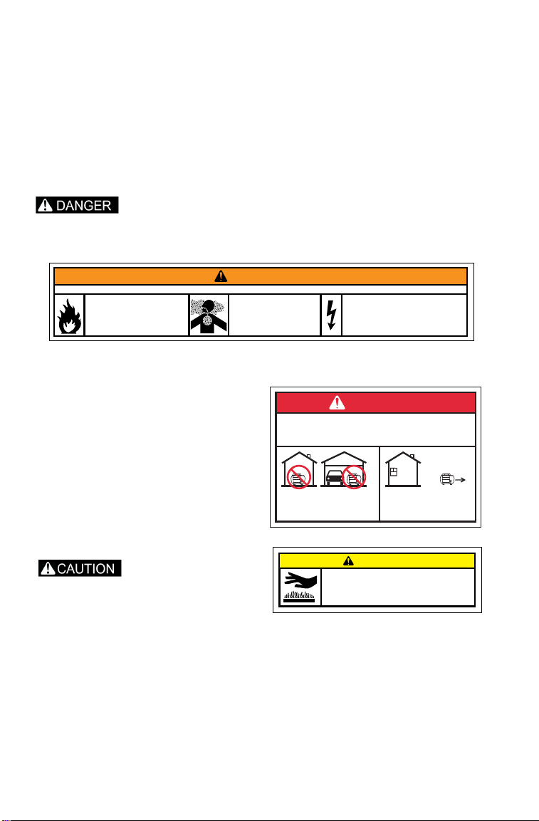
Warnings, Cautions and Notices
Signal Words and Safety Terms
The following signal words and symbols appear throughout this manual.
Your safety, and the safety of others, is involved when these words and
symbols are used. Become familiar with their meaning before reading
the manual.
A safety alert warning indicates a hazardous situation which, if not
avoided, may result in death or serious injury.
A safety alert caution indicates a hazardous situation which, if not
avoided, may result in minor or moderate injury.
A notice is used to address practices not related to physical injury.
IMPORTANT: Key reminders during assembly, disassembly, and inspection
of components.
Note: Key information to clarify instructions.
ALCOHOL OR DRUG USE
Operating the generator after consuming alcohol or drugs could adversely
affect operator judgement. Never consume alcohol or drugs before or
while operating the generator.
5
Page 7
INTRODUCTION
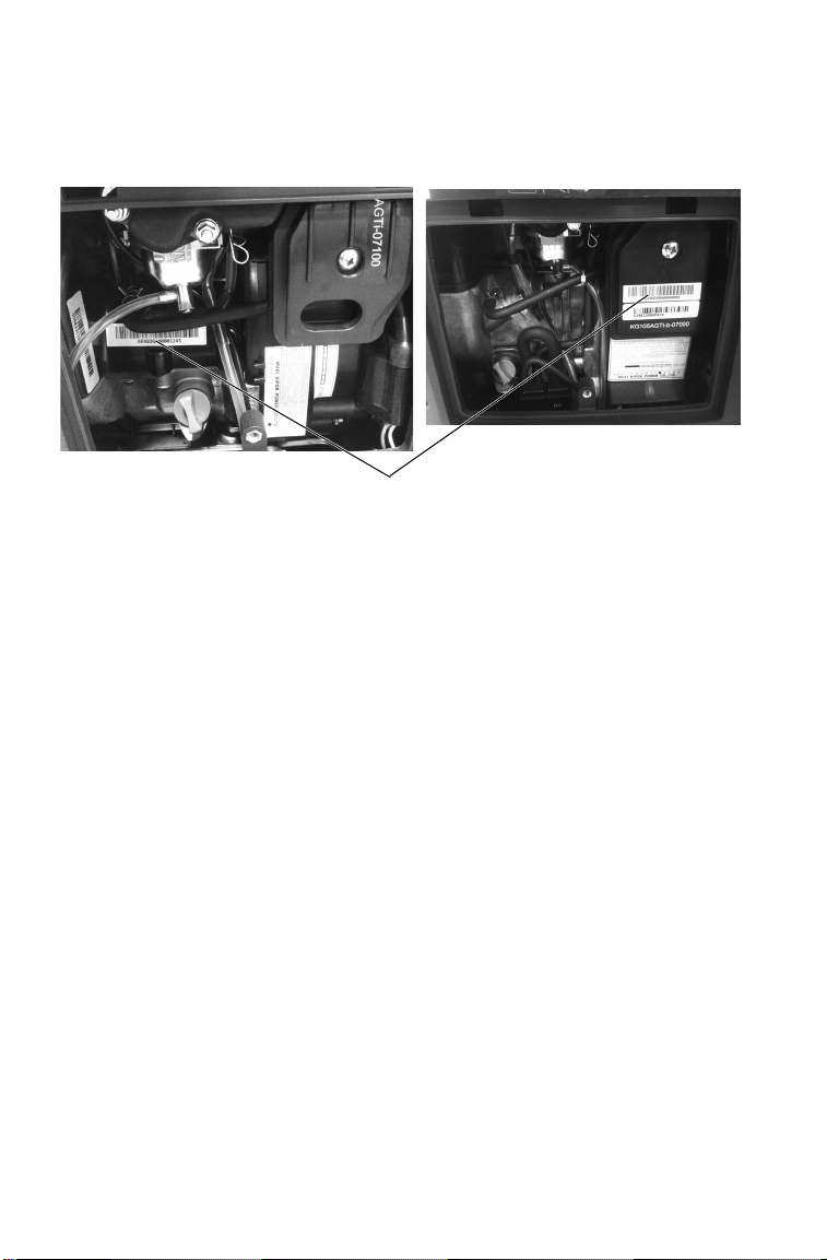
Serial Number
P1000i
P2000i
Identification Numbers and Locations
Record your generator’s identification numbers in the space provided.
The model and serial number decal is located inside the service door.
MODEL NUMBER: ______________________________________________________
SERIAL NUMBER: ______________________________________________________
PURCHASE DATE: ______________________________________________________
PURCAHSE LOCATION:__________________________________________________
6
Page 8

SAFETY
Safety Warnings and Precautions
IMPORTANT SAFEY INSTRUCTIONS. SAVE THESE
INSTRUCTIONS.
Failure to follow recommended precautions and procedures could result
in severe injury or death. Always read all safety precautions and follow all
operation, inspection, and maintenance procedures outlined in this
manual.
General
• Read and understand all of the safety and operating information in
this manual and on the product before using the machine. Use the
generator only as described in this manual.
• Understand and follow all inspection and maintenance procedures
outlined in this manual. Following these procedures will ensure that
the generator remains in safe operating condition.
• Turn off the petrol valve and close the fuel cap vent when the
generator is not in use.
It is the responsibility of the owner to ensure that all users of this
generator are fully informed of the safety and operating information prior
to use.
Before and During Operation
• Preform all Pre-Inspection activities as shown on page 25 of this
manual. Inspect and tighten all parts regularly. Ensure the generator
does not have any damaged, loose, or missing parts before use. All
defects should be corrected before use. Do not operate the generator if
it has been dropped or damaged until all defective parts have been
repaired.
• Do not place any flammable materials near the generator.
• Never start the generator or let it run in an enclosed area. Exhaust
vapors are poisonous and can cause loss of consciousness or death in
a short time. Keep the generator away from buildings and other
equipment during operation.
7
Page 9

SAFETY
Safety Warnings and Precautions
Before and During Operation
• Do not operate the generator in exposed locations where it will be
subjected to wet conditions.
• Do not touch the generator with wet hands, as this may cause severe
electric shocks.
• Do not pour water directly over the generator or wash it.
• Do not use or store the generator in the rain or snow.
• Do not cover the generator when in use.
• Always operate the generator on a firm, flat, and level surface, as the
generator will vibrate on an irregular surface. If the generator is tilted,
fuel may spill or the generator may tip over, causing a hazardous
situation.
• Do not connect the generator to another power supply source.
• The engine becomes extremely hot during and immediately after it
has been in use. Be careful not to touch any parts of the hot engine,
especially the muffler or muffler cover, or serious burns may result.
• Do not connect external equipment to the generator before starting
the engine.
• Do not use for life support, or life sustaining systems.
• The output of this generating set is potentially lethal. The set should
not be connected to a fixed electrical installation except by an
appropriately licensed person.
• Do not operate in a hazardous location, e.g. where there may be a risk
of explosion of petrol fumes, leaking gas or explosive dusts.
• Do not operate in a confined area where exhaust gases, smoke or
fumes could reach dangerous concentrations.
• Do not refuel while engine is running.
Fire Safety
Generator exhaust system gets hot enough to ignite some materials and
burn skin if touched.
• Keep the generator away from buildings, other equipment, and
combustible materials during operation.
• Do not enclose the generator in any structure.
8
Page 10

SAFETY
Safety Warnings and Precautions
Fire Safety
• Keep the generator away from buildings, other equipment, and
combustible materials during operation.
• Do not enclose the generator in any structure.
• Keep children and pets away from generator.
• Exhaust system components are very hot during and after use. Hot
components can cause burns and fire. Do not touch the hot exhaust
system components. Always keep combustible materials away from
the exhaust system.
• Ensure that any spilled fuel is properly wiped up prior to using the
generator as fuel vapors are flammable.
Operator Safety
Operating the generator with worn, damaged, or malfunctioning
components could result in serious injury or death. Never start the engine
without checking all of the generator components to be sure of proper
operation.
• Read and understand all of the safety and operating information in
this manual and on all warning labels before using the generator. Use
the generator only as described in this manual.
• Know how to stop the generator quickly in case of emergency, see
page 30 for information on stopping the unit quickly.
• Keep children, pets, and bystanders at a safe distance from the
generator.
• Review and understand the use of all generator controls.
• Be sure that anyone who operates the generator receives proper
instruction. Do not let children operate the generator.
• Use the generator only for intended purposes.
• Turn off the generator immediately if the unit begins to operate
abnormally. After the generator has cooled, disconnect the generator
and call your authorized POLARIS supplier.
• While operating the generator, if you experience headache, fatigue,
nausea / vomiting, confusion, or seizures, immediately get to fresh
air. Do not delay and do not attempt to shut down the unit.
• Run the generator on flat, dry surfaces only. The generator can only
be run while stationary. Do not run the generator on any moving
vehicle or objects.
9
Page 11

SAFETY
Safety Warnings and Precautions
Fuel Safety
Petrol is highly flammable and explosive under certain conditions. Always
use caution when handling petrol.
• Petrol is extremely flammable, and petrol vapor can explode. Before
refueling allow the engine to cool completely if the generator has
been in operation.
• Always store petrol in an approved container.
• Always refuel outdoors or in a well-ventilated area away from any
combustible materials.
• Do not smoke or allow open flames or sparks in or near the area
where refueling is performed or where petrol is stored.
• Never permit children to handle petrol.
• Never refuel around bystanders, pets, and flammable objects.
• Loosen the fuel cap slowly to relieve pressure in the tank.
• Take care not to overfull or spill any fuel on the generator or muffler
when refueling.
• If petrol spills on skin or clothing, immediately wash it off with soap
and water and change clothing.
• Do not use the generator if you observe leaking petrol. Have the
generator serviced immediately and before using it again.
• When operating or transporting the generator, be sure it is kept
upright. If it tilts, fuel may leak. Be sure the fuel tank cap is tightened
when transporting the generator.
• Do not refuel using petrol station pumps.
• Remove fuel from the generator before transporting in a vehicle.
Do not swallow petrol, inhale petrol vapors, or spill petrol. If you swallow
petrol, inhale more than a few breaths of petrol vapor, or splash petrol in
your eyes, see a physician immediately. If petrol spills on skin or clothing,
immediately wash it off with soap and water and change clothing.
10
Page 12

SAFETY
Safety Warnings and Precautions
Carbon Monoxide Safety
Generator exhaust contains Carbon Monoxide (CO) vapors. Exposure to
Carbon Monoxide by people or pets can result in SEVERE INURY or
DEATH. ALWAYS operate generate according to guidelines in labels and
this manual.
• This portable generator runs on petrol. The generator exhaust vapor
contains carbon monoxide (CO).
• Carbon monoxide is odorless. You cannot smell it.
• Carbon monoxide is colorless. You cannot see it.
• Never run an engine in an enclosed area. Exhaust contains poisonous
carbon monoxide vapor that can cause loss of consciousness or death.
Operate the engine in an open area, and well ventilated. The generator
is for outdoor use only.
• Do not use the generator indoors in garages, basements, crawl spaces,
sheds, portable buildings, or similar areas even if doors and / or
windows are open or if ventilating fans are used to circulate air.
• Do not use the generator near windows, doors, vents or any other
building openings even if they are closed. Poor seals on a door, as just
one example, could still permit high levels of carbon monoxide to
infiltrate the living area of a home.
• Be sure to install approved carbon monoxide detectors in your home
that have battery back-up systems that will continue to detect the
presence of carbon monoxide during electric-power outages. Test
these devices and replace batteries as recommended by their
respective manufacturers.
• If you experience headache, fatigue, nausea / vomiting, confusion, or
seizures, immediately get to fresh air and away from the unit. Do not
delay for any reason.
• Do not run the generator directly on grass or with the exhaust pipe
close to plants or grass. Exhaust gas temperature will be high.
11
Page 13

SAFETY
Safety Warnings and Precautions
Electrical Safety
This generator produces high voltage electricity.
• The generator produces enough electric power to cause serious shock
or electrocution if misused.
• Always connect the generator to a suitable ground circuit.
• When servicing the generator, disconnect the spark plug wire and
place it where it cannot contact the plug. Turn the engine switch to the
OFF position.
• Do not check for a spark with the plug removed. Use only approved
spark plug testers.
• Using a generator or electrical appliance in wet conditions, such as
rain or snow, or near a pool or sprinkler system, or when your hands
are wet, could result in electrocution. Keep the generator dry and
away from all sources of moisture.
• Do not store the generator outdoors unprotected from the weather.
• If the Generator has been subjected to water, moisture, or ice check
all of the electrical components on the control panel before each use.
Moisture or ice can cause a malfunction or short circuit in electrical
components that could result in electrocution.
• Do not connect the generator to a building’s electrical system unless
an isolation switch has been installed that meets applicable electrical
codes and regulations.
• To avoid overloading the generator, ensure that the load is kept within
the rating stated on the generator. Overloading will damage the unit
and / or shorten its operating lifespan.
• Both the P1000i and P2000i can be paralleled with another P1000i or
P2000i using the POLARIS parallel kit.
• Do not over charge a battery with the DC receptacle, over charging
the battery may result in battery damage and potential ignite if a spark
is introduced.
12
Page 14

SAFETY
Safety Warnings and Precautions
Extension Cord Information
• Read the manufacturer starting and running wattage details and
operating instructions for the device(s) and appliance(s) that will be
used. Often this information can be found in the owner's manual or on
specification decals on the device or appliance.
• POLARIS recommends using only U.L. (Underwriters Laboratories,
Inc.) approved extension cords labeled with the use, size, and wattage
rating. Only use heavy-duty extension cords with a three-prong
(grounded) plug for your safety. Decide on what length extension
cord is required as cord length determines the extension cord gauge.
Remember, as the cord gets longer, the current capacity of the cord
decreases.
• Never use an extension cord designated as “indoor use only”
outdoors.
• Store all extension cords indoors when not in use. Outdoor conditions
can deteriorate a cord over time.
• Never keep an extension cord plugged in when not in use. The cord
will still conduct electricity until it is unplugged from the outlet.
• Before plugging an extension cord or power cord into the generator,
check the cord for any signs of damage.
Equipment Modifications
Modifying the generator by adding or removing any equipment not
approved by POLARIS may void the warranty. Such modifications may
make the generator unsafe to operate and could result in severe injury to
operators and / or bystanders, as well as damage to the generator. Some
modifications may not be legal in your area. If in doubt, contact your
authorized POLARIS supplier.
13
Page 15
SAFETY
WARNING
Improper Generator use can result in SEVER E INJURY or DEATH. Read the Owner’s Manual. Follow all instructions and Warnings.
Generatorexhaust contains poisonous
Carbon Monoxide (CO) vapors. ALWAYS
operate in a well-v entilated area.
NEVER operate in a home, garage, enclosed
area or near windows, doors, or people.
NEVER operate near ammable objects.
Petrol is ammable and explosive. Severe
burns can result. ALWAYS stop engine and let
cool bef
ore refueling. ALWAYS checkfor fuel
leaks and wipe up any spills. ALWAYS turn fuelto
OFF when not in use. NEV ER handle petrol
indoors. NEVER overll fuel tank.
Electrocution can result from using generator inrain,
snow, nearwater, withwet hands, or with improper
connections. ALWAYS keep generator and surrounding
area dry. NEVERconnect generator to any building
without electrical-isolation protection that meets
applicable
codes and regulat ions.
DANGER
Using a generator indoors CAN KILL YOU IN MINUTES.
Generator exhaust contains carbon monoxide.
This is a poison you cannot see or smell.
NEVER use inside a home
or garage. EVEN IF doors
and windows are open.
Only use OUTSIDE and
far away from windows,
doors, and vents.
CAUTION
Contacting a hot exhau st system
can cause serious burns.
Do not touch if generator is or has
been running.
Safety Labels and Locations
Safety and warning decals have been placed on the generator for your
protection. Read and follow the instructions of the decals and warnings
on the generator carefully. If any of the decals depicted in this manual
differ from the decals on your generator, always read and follow the
instructions of the decals on the generator.
Carbon Monoxide Warning
Using a generator indoors CAN KILL YOU IN MINUTES.
The carbon monoxide warning is located on top of the generator.
Outdoor Use ONLY Danger Label
Generator Exhaust contains carbon
monoxide. This is a poison you
cannot see or smell.
NEVER use inside a home or
garage, EVEN IF doors and
windows are open.
Only use OUTSIDE and far away
from windows, doors, and vents.
Hot Exhaust Caution
The hot exhaust caution is located
on the muffler cover.
Contacting a hot exhaust system
can cause serious burns.
Do not touch if generator is or has been running.
14
Page 16

SAFETY
Safety Labels and Locations
Improper Generator use can result in SEVERE INJURY or DEATH. Read the
OWNER’S MANUAL. Follow all Instructions and Warnings.
Petrol is flammable and explosive. Severe burns can result. ALWAYS stop
the engine and let cool down before refueling. ALWAYS check for fuel
leaks and wipe up any spills. ALWAYS turn the fuel to OFF when not in
use. NEVER handle petrol indoors. NEVER overfill the fuel tank.
Generator exhaust contains poisonous Carbon Monoxide (CO) vapors.
ALWAYS operate in a well-ventilated area. NEVER operate in a home,
garage, enclosed area or near windows, doors, or people. NEVER operate
near flammable objects.
Electrocution can result from using generator in rain, snow, near water,
with wet hands, or with improper connections. ALWAYS keep generator
and surrounding area dry. NEVER connect generator to any building
without electrical-isolation protection that meets applicable codes and
regulations.
15
Page 17
CONTROLS AND FEATURES
A
B
C
D
E
F
G
H
I
J
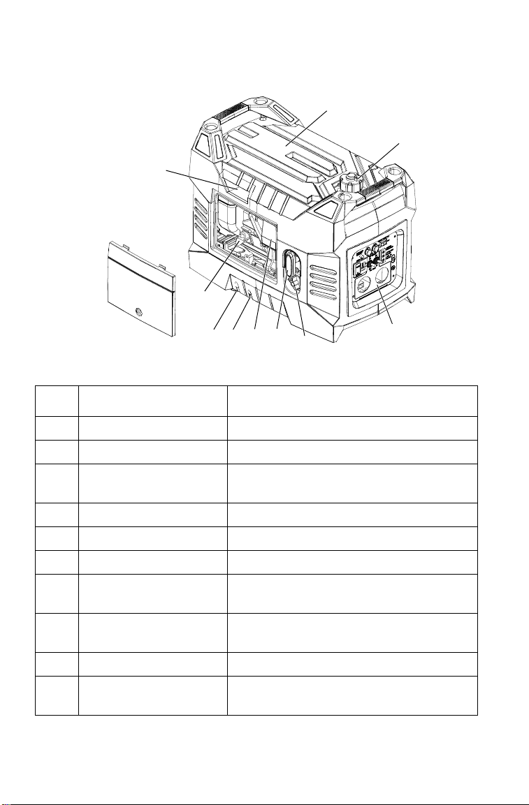
Generator Components:
ITEM NOMENCLATURE DESCRIPTION
A Spark Plug Cap Remove the top to access the spark plug
B Control Panel Generator controls
C Air Filter
D Oil Dipstick Measures oil level in the engine
E Carburetor Vent Hose Atmospheric vent
F Carburetor Drain Hose Drains fuel from the carburetor
G Starter Recoil Grip
H Choke Lever
I Fuel Tank Cap Accesses fuel tank
J Engine / Fuel Switch
Protects the air flow to the carburetor from
becoming obstructed with debris
Causes the recoil starter to crank the engine
when pulled
Provides proper starting mixture when
engine is cold
Controls the ignition system and the fuel
valve
16
Page 18

CONTROLS AND FEATURES
K
Q
R
S
U
O
P
U
K
Q
R
O
S
P
N
M
T
T
N
M
P1000i
P2000i
Control Panel Components:
ITEM NOMENCLATURE DESCRIPTION
K SMART Throttle Switch
M DC Fuse Protector Protects DC charging circuit from overloads
N 12V DC Receptacle Charges 12V DC batteries
O Ground Terminal
P 240V AC Receptacles
Q Output Indicator
R Overload Indicator
S Low Oil Indicator
T Overload Reset Switch Resets the circuit after an AC overload
U Parallel Receptacles For use with proper POLARIS Parallel kits
Automatically reduces engine speed when
loads are shut off or disconnected
Provides ground for non-conductive metal
parts and receptacle ground terminals
Provides two connections for properly rated
AC appliances
Illuminates GREEN when the generator is
operating normally
Illuminates RED for appliance short circuits
or overloads
Illuminates RED prior to the oil level falling
below a safe limit
17
Page 19

CONTROLS AND FEATURES
OFF
ON
ON
OFF
G
J
Choke Lever
Move the choke lever (H) to the START
position when starting a cold engine.
Slowly move the choke lever to the RUN
position as the engine RPM stabilizes.
Fuel Tank Cap Vent Lever
When the engine is well-cooled and not
in use, the fuel tank cap vent lever (I)
must be placed in the OFF position to
reduce the possibility of fuel leakage.
The vent lever must be in the ON
position to allow the engine to operate.
Engine Fuel Switch
The engine switch (J) controls the
ignition system and the fuel valve. ON:
opens the fuel valve and allows the
engine to be started. OFF: closes the fuel
valve and shuts off the engine.
Starter Recoil Grip
Do not allow starter grip to snap back against the generator. Return it
gently to prevent damage to the starter.
The starter recoil grip (G) causes the recoil starter to crank the engine
when pulled.
18
Page 20

CONTROLS AND FEATURES
M
N
SMART Throttle Switch
The SMART throttle switch (K)
automatically reduces engine speed
when loads are shut off or disconnected.
The engine returns to the proper speed to
power the electrical load when
appliances are turned ON or reconnected.
Press the SMART throttle switch to the
OFF position to reduce voltage changes
when high electrical loads are
simultaneously connected or when using
the DC output.
DC Receptacle and Fuse
The DC receptacle (N) is protected
from an overload with a fuse. If the
DC circuit is overloaded, the 5 amp
fuse (M) will blow and power to the
DC receptacle will cease. The red
light on the DC panel will illuminate.
The fuse is located to the left of the
receptacle and is accessed by
snapping open the access door. See
details on page 35. Replace the fuse
with one of the same capacity. Using
a higher rated fuse may cause damage
to the generator alternator.
The DC receptacle charges 12V DC automotive-type batteries. The DC
charging output is not regulated. The 12V DC receptacle has no battery
overcharge protection function. Do not overcharge the battery.
19
Page 21
CONTROLS AND FEATURES
P1000i P2000i
Q
R
S
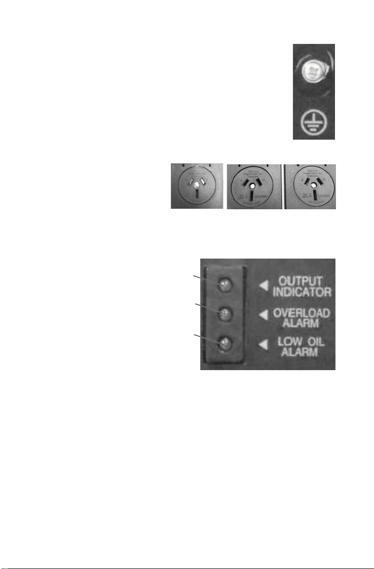
Ground Terminal
The ground terminal (O) connects to the frame of the
generator, metal parts that do not conduct current, and
ground terminals of each receptacle. Consult a qualified
electrician, electrical inspector, or local agency having
jurisdiction for local codes or ordinances for the
intended use of the generator before using the ground
terminal.
AC Receptacles
The AC receptacles (P)
provide connections for
properly rated AC appliances,
see page 62 for specifications.
Indicator Panel
Output Indicator
The output indicator (Q)
illuminates GREEN when the
generator is in normal operation
and producing electrical power at
the receptacles.
Overload Indicator
The overload indicator (R)
illuminates RED if there is a short
circuit in the connected
appliance(s), or if the generator is
overloaded. The light remains
illuminated for 5 seconds, then the
current to the connected appliance
is shut off and the output indicator
light (GREEN) extinguishes.
Low Oil Indicator
The low oil indicator (S) illuminates RED before the oil level falls
below a safe limit and the detection system automatically stops the
engine. When there is a low engine oil level at startup, the engine will be
prevented from starting.
20
Page 22

CONTROLS AND FEATURES
Overload Protector Reset Switch
Should the generator overload, AC power will be cut
off but the engine will stay running. Correct the
overload condition and then press the overload reset
switch (T) on the front panel. AC power will be
restored immediately.
Parallel Receptacles
Two POLARIS parallel ready generators can be
connected together to increase the total power
available to a load, using the parallel receptacles (U).
The system seamlessly matches frequency and
automatically evenly distributes the load to each
generator so one is not overloaded. Contact your
supplier for the proper kit for your particular application. Only
POLARIS parallel kit (PN 3410252) can be used for POLARIS
generator parallel power output.
21
Page 23
FIRST USE INSTRUCTIONS
A
Upper Level
B
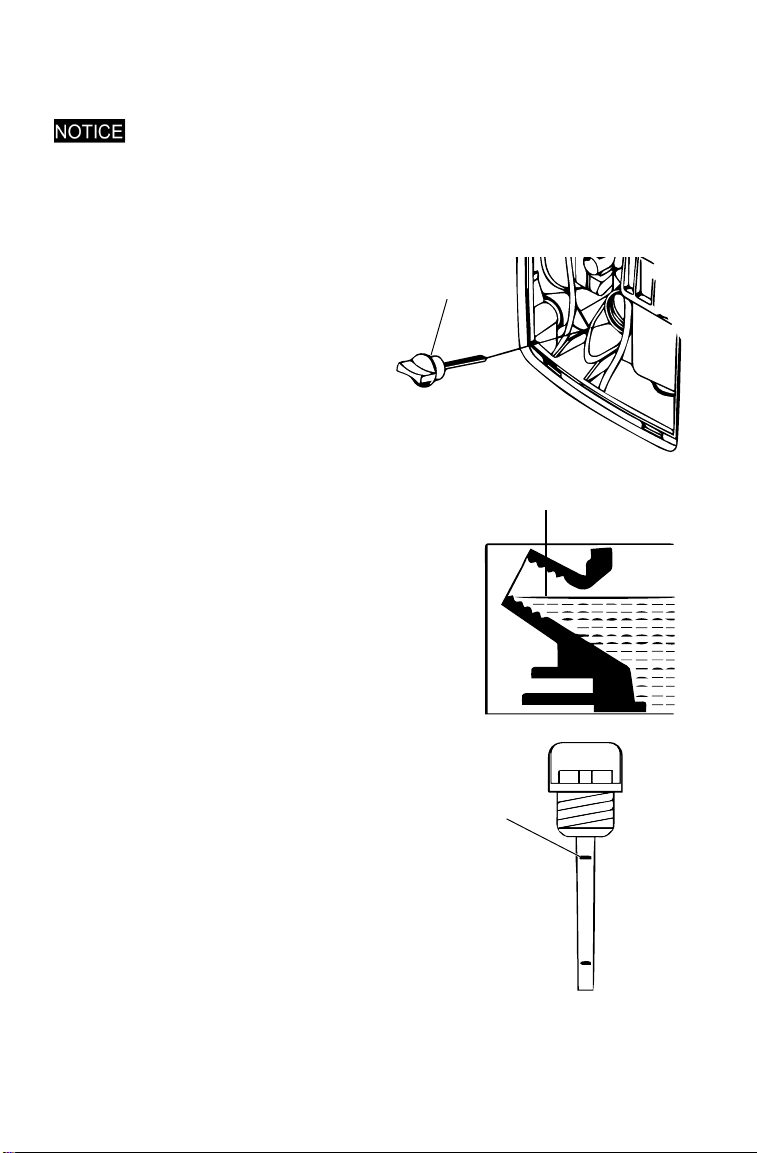
Adding Engine Oil
Failure to use the recommended 4-stroke engine oil may result in engine
damage, see page 62 for recommended oil and capacity.
1. Place generator on flat, level surface. Open the service door. See
page 46.
2. Remove the oil filler cap /
dipstick (A).
3. Fill the engine crankcase with the
specified amount of engine oil. See
page 62.
4. Insert the dipstick into the filler
neck, without screwing it in.
5. Remove the dipstick and verify that
the oil level is at the upper limit (B).
Add additional oil and inspect the
level as needed until the upper limit
has been reached.
6. Re-install the dipstick (A). Use a
clean shop rag to clean any spilled
oil.
7. Re-install the service door.
22
Page 24

FIRST USE INSTRUCTIONS
Fuel Recommendation
POLARIS recommends the use of 91 octane fuel or higher. Do not use
fuel containing more than 10% ethanol. Do not use petrol containing
methanol.
IMPORTANT: Operating the generator with an obstructed fuel system will
result in serious engine damage. Perform maintenance as recommended.
IMPORTANT: Thoroughly read “Safety” section and all safety information
when handling fuel.
IMPORTANT: In order to insure the optimum output and the maximum
service life of the generator, the generator should run at a 50% load for the
first 20 hours.
Petrol is highly flammable and explosive and can cause serious injury.
Stop the engine and keep heat, sparks, and flame away. Handle fuel only
outdoors. Wipe up spills immediately.
Do not spill fuel when filling the fuel tank. Damage caused by spilled fuel
is not covered under warranty. Spilled fuel is a fire hazard, causes
environmental damage, and can damage paint and plastic. Wipe up spills
immediately. Do not fill above bottom of strainer.
Refuel in a well ventilated area before starting the engine. If the engine has
been running, allow it to cool.
Never refuel the engine inside a building where vapors may reach flames
or sparks. Keep fuel vapors away from electrical appliances.
23
Page 25

FIRST USE INSTRUCTIONS
Loosen
Tighten
A
C
B
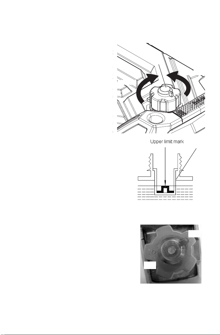
Adding Fuel
1. Remove the fuel tank cap (A).
2. Fill carefully to avoid spilling fuel on
the fuel tank strainer (B). Do not
overfill the fuel tank (there should be
no fuel above the upper limit mark).
3. Securely tighten the fuel tank cap (A).
4. Position the fuel tank vent lever (C) OFF for storage or transport, or
ON to operate the generator.
5. Move generator away from the fueling source and site before
starting the engine.
After refueling, securely reinstall the fuel tank cap (A).
24
Page 26

PRE-OPERATION INSPECTION
Note: Always perform the recommended pre-operation inspections before each
use. Always perform the inspections at the beginning of a project and
when removing the generator from storage.
Failure to perform the recommended pre-operation inspections could
result in minor or moderate injury or property damage. When inspection
reveals the need for adjustment, replacement, or repair, perform service
promptly.
Pre-Operation Checklist
Open the service door to expose the generator inner components. See
page 46.
Engine Oil
Perform “Oil Level Inspection” (see page 49). Add oil as needed.
Fuel Line
Petrol is highly flammable and explosive and can cause serious injury.
Stop the engine and keep heat, sparks, and flame away. Handle fuel only
outdoors. Wipe up spills immediately.
Inspect the fuel hose for cracks or damage. Replace as needed.
Fuel Level
Check the fuel level and refuel as needed. See page 26.
Exhaust System
If the engine has been running, the muffler will be very hot. Allow the
muffler to cool before servicing.
Inspect the exhaust system for leakage. Tighten or replace the gasket as
needed.
Carburetor
Inspect the choke lever operation.
Starting System
Inspect the recoil starter operation. Verify the starter recoil grip
functions properly.
Air Filters
Inspect the air filters. Clean or replace as needed. See page 25.
25
Page 27

OPERATION
Safe Operating Precautions
Fuel Recommendations
The generator engine is certified to operate on regular unleaded petrol
with a pump octane rating of 91 or higher.
Never use stale or contaminated petrol or an oil /petrol mixture. Avoid
getting dirt or water in the fuel tank.
The use of regular unleaded petrol containing no more than 10% ethanol
(E10) by volume is permitted. Do not use petrol containing methanol. If
the content of ethanol or methanol exceeds the specified limits, it may
cause starting or performance problems. It may also damage metal,
rubber, and plastic parts of the fuel system. Damage due to ethanol or
methanol is not covered under warranty.
Refueling
IMPORTANT: Thoroughly read the “Safety” section and all warnings and
cautions when handling fuel.
Petrol is highly flammable and explosive and can cause serious injury.
Stop the engine and keep heat, sparks, and flame away. Handle fuel only
outdoors. Wipe up spills immediately.
Do not spill fuel when filling the fuel tank. Damage caused by spilled fuel
is not covered under warranty. Spilled fuel is a fire hazard, caused
environmental damage, and can damage paint and plastic. Wipe up spills
immediately. Do not fill above bottom of strainer.
Refuel in a well ventilated area before starting the engine. If the engine has
been running, allow it to cool.
Never refuel the engine inside a building where vapors may reach flames
or sparks. Keep fuel vapors away from electrical appliances.
26
Page 28
Safe Operating Precautions
Loosen
Tighten
A
B
OFF
ON
Refueling
1. Remove the fuel tank cap (A).
2. Fill carefully to avoid spilling
fuel or exceeding the bottom of the
fuel tank strainer (B).
OPERATION
3. Securely tighten the fuel tank cap
(A) until it clicks.
4. Position the fuel tank vent lever OFF
for storage or transport, or ON to
operate the generator, if equipped.
5. Move generator at least 10 feet (3
meters) away from the fueling source
and site before starting the engine.
27
Page 29

OPERATION
DANGER
Using a generator indoors CAN KILL YOU IN MINUTES.
Generator exhaust contains carbon monoxide.
This is a poison you cannot see or smell.
NEVER use inside a home
or garage. EVEN IF doors
and windows are open.
Only use OUTSIDE and
far away from windows,
doors, and vents.
Safe Operating Precautions
Before Starting the Engine
Read, understand, and follow the
Safety Section of this manual.
1. Ensure the generator is away
from the fueling source.
2. The generator will vibrate
during operation. Place the
generator in a dry location and
on a flat, level surface.
3. Unplug all power cords and
extension cords from the
generator.
Starting the Engine
1. Position the fuel tank cap vent lever to ON.
2. Position the SMART throttle switch
to OFF.
3. For a cold engine start, position the
choke lever to START. To restart a
warm engine, leave the choke lever
in the RUN position.
28
Page 30

OPERATION
ON
OFF
AC
Switch
Safe Operating Precautions
Starting the Engine
4. Position the engine switch to ON.
5. Lightly pull the starter recoil grip until resistance is felt. Then,
firmly pull straight out.
Do not allow starter grip to snap back
against the generator. Return it gently
to prevent damage to the starter.
6. If the choke lever was positioned to START the engine, gradually
move it to RUN as the engine warms up.
7. After a 2 to 3-minute warm up, select ON or OFF on the SMART
throttle switch as desired.
8. If connecting loads to generator, reference “AC Operation” or “DC
Operation” as outlined later in this section.
9. Make sure to turn the AC switch
to "ON" position. Otherwise,
there will be no AC power
output from AC receptacles.
29
Page 31

OPERATION
ON
OFF
OFF
ON
Safe Operating Precautions
Stopping the Engine
In case of emergency, position the engine switch to OFF to stop the
engine. Under normal conditions, perform the following procedure.
1. Shut off or disconnect all appliances connected to the generator.
2. Position the engine switch to
OFF.
3. Allow the engine to cool and
position the fuel tank cap vent
lever to OFF.
30
Page 32

OPERATION
A
B
Safe Operating Precautions
AC Operation
Before connecting a device or power cord to the generator, ensure it is in
good condition. Faulty appliances or power cords can create a potential
for electrical shock.
If an appliance begins to operate abnormally, becomes sluggish, or
suddenly stops, immediately shut it off. Disconnect the appliance and
determine whether the problem is the appliance or if the rated load
capacity of the generator has been exceeded.
Ensure the combined electrical rating of the device or appliance does not
exceed the maximum allowed by the generator. Never exceed the
maximum power rating of the generator. Power levels between rated and
maximum may be used for no more than 30 minutes.
Note: When the electric motor starts, the overload indicator (middle light) may
illuminate (RED) and extinguish within 4 seconds. If the overload indicator
remains illuminated, consult the generator supplier.
Note: In order to insure the optimum output and the maximum service life of the
generator, the generator should run at a 50% load for the first 20 hours
1. Start the engine and ensure that
the output indicator (A)
illuminates (GREEN).
2. Plug the device or extension cord
into one of the AC receptacles
(B).
3. Turn on the device.
Note: If the generator is overloaded or if
there is a short circuit in a
connected appliance, the overload
indicator (RED) will illuminate. The
overload indicator will remain
illuminated and, after about 4
seconds, current to the connected
appliance(s) will shut off but the
engine will stay running. The output
indicator (GREEN) will extinguish.
4. If overloaded or short circuit in a connected device occurs, stop the
engine and refer to the “Troubleshooting” section. Determine if the
cause is a short circuit in the connected device or an overload.
Correct the problem and restart the generator.
5. After determining the cause of the overload and when it is safe to
resume using the AC power in order to correct the overload
condition and then press the overload reset switch on the front
panel. AC power will be restored immediately.
31
Page 33

OPERATION
Safe Operating Precautions
AC Capacity
In case of substantial overloading, the electronic circuit protector will
activate. Slightly overloading the generator or running at maximum
power operation (30 minutes) may not switch the circuit ON, but will
shorten the service life of the generator.
Maximum power is:
(see page 62)
For continuous operation, do not exceed rated power:
(see page 62)
Consider the total power requirements of all connected devices.
Appliance and power-tool manufacturers usually list the rating
information near the model or serial number. After plugging in a device,
allow the generator to stabilize before plugging in additional items.
Always consider the generator capacity before plugging in any device.
32
Page 34

OPERATION
Safe Operating Precautions
AC Capacity
Note: Typical wattages are listed in the table below. Before plugging any device
into the generator, verify the manufacturer-listed wattage on the device.
Wattage Reference Table
DEVICE
Circular Saw - 7 1/4” 1400 2300
Coffee Maker 1000 0
Dehumidifier 650 800
Electric Drill - 3/8”, 4 Amps 440 600
Hair Dryer 300 - 1200 0
Light Bulb (75-Watt) 75 0
Microwave Oven1000-Watt 1000 1400
Paint Sprayer 360 1080
Heat Pump 4700 4500
Personal Computer with 17”
Monitor
Radio 300 300
Refrigerator 400 - 800 2200
Space / Wall Heater 1800 0
Table Saw / Radial Arm Saw 10”
Do not use or only use with the POLARIS Parallel Kit, see page 38 for more
information
High-Pressure Washer-1 HP 1200 3600
Garage Door Opener 1/2 HP 875 2350
Sump Pump - 1/2 HP 1050 2200
Central AC Unit48,000 BTU 6000 7800
Television (Color) - 27” 500 0
Air Compressor - 1 HP 1600 4500
RUNNING
(RATED) WATTS
800 0
2000 2000
ADDITIONAL
STARTING (SURGE)
WATTS
33
Page 35

OPERATION
Safe Operating Precautions
Power Management
DEVICE
Paint Sprayer 360 1080
Radio 300 300
RUNNING
(RATED) WATTS
ADDITIONAL
STARTING (SURGE)
WATTS
Total Running (Rated) Watts = 660
Additional Starting Surge Watts = 1380
Total Generator Output Required = 2040
Ensure the combined electrical rating of the powered device(s) do not
exceed the maximum allowed by the generator. Never exceed the
maximum power rating of the generator. Power levels between rated and
maximum may be used for no more than 30 minutes.
DC Operation
Connecting the Battery Charging Cable (included)
The battery emits explosive hydrogen gas during normal operation. A
spark or flame can cause the battery to explode with enough force to kill
or cause serious injury. Wear protective clothing and eye protection when
charging a battery.
Battery posts, terminals, and related accessories contain lead and lead
components. Wash hands after handling.
The DC charging output is not regulated. The DC receptacle should only
be used for charging 12V DC batteries.The 12V DC receptacle has no
battery overcharge protection function. Do not overcharge the battery.
When using the DC output, position the SMART throttle switch to OFF.
The DC receptacle may be used while the AC power is in use.
34
Page 36

OPERATION
Safe Operating Precautions
DC Operation
Connecting the Battery Charging Cable (included)
1. Position the SMART throttle switch
to OFF.
2. Disconnect the vehicle ground cable
from the negative (-) battery
terminal.
3. Plug the battery charging cable into
the DC receptacle. See page 19.
4. Connect the red lead of the battery charging cable to the positive (+)
battery terminal and then the black lead to negative (-) battery
terminal.
Start the generator
Do not start the vehicle while the battery charging cable is connected and
the generator is running. The vehicle’s charging system or the generator
may be damaged.
An overloaded DC circuit, excessive current draw by the battery, or a
wiring problem will trip the DC circuit fuse. If this happens, The fuse must
be replaced before the DC receptacle is operative. Replace the fuse with
one of the same size and rating (5 amp). Exceeding the current rating may
lead to alternator damage. If the DC circuit protector fuse continues to trip,
discontinue charging and see your authorized POLARIS generator
supplier.
The circuit protector does not prevent
overcharging the battery. Over charging
the battery may result in battery damage
and potential ignite if a spark is
introduced.
35
Page 37

OPERATION
Safe Operating Precautions
DC Operation
Disconnecting the Battery Charging Cable:
1. Stop the generator.
2. Disconnect the black lead of the battery charging cable from the
negative (-) battery terminal and then the lead from the positive (+)
battery terminal.
3. Unplug the battery charging cable from the DC receptacle. See page
19.
4. Connect the vehicle battery ground cable to the negative (-) battery
terminal.
SMART Throttle System
With the SMART throttle switch in the ON position, engine speed is
automatically lowered when loads are reduced, turned off, or
disconnected. When devices are turned on or connected, the engine
returns to the proper speed to power the electrical load. When the smart
throttle is in the OFF position, the engine runs at rated load RPM
Appliances with large start-up power demands may not allow the engine
to reach normal operating RPM when they are connected to the
generator. Position the SMART throttle switch to OFF and connect the
device to the generator. If the engine still will not reach normal
operating speed, ensure the device does not exceed the rated load
capacity of the generator.
If high electrical loads are simultaneously connected, position the
SMART throttle switch to OFF to reduce voltage changes.
The SMART throttle system is not
effective for use with devices or
appliances requiring only momentary
power. If the device or appliance will be
quickly turned on and off, the SMART
throttle switch should be in the OFF
position. When using the DC output,
position the SMART throttle switch to
OFF.
36
Page 38

OPERATION
Safe Operating Precautions
Standby Power
Improper connection to a building electrical system can allow current from
the generator to back feed into the utility lines. Such back feed may
electrocute utility company workers or others who contact the lines during
a power outage. Additionally, the generator may explode, burn, or cause
fires when utility power is restored. Consult the utility company or a
qualified electrician prior to making any power connections.
Connections to a Building Electrical System
Connections for standby power to a building's electrical system must be
made by a qualified electrician and must comply with all applicable
laws and electrical codes. Improper connections can allow electrical
current from the generator to back feed into the utility lines. Such back
feed may electrocute utility company workers or others who contact the
lines during a power outage; when utility power is restored, the
generator may explode, burn, or cause fires in the building's electrical
system. Do not connect this generator to an automatic transfer switch.
Serious damage to the engine and inverter module may result.
In some areas, generators are lawfully required to be registered with
local utility companies. Check local regulations for proper registration
and usage procedures.
System Ground
To prevent electrical shock from faulty appliances, the generator should
be grounded. Connect a length of heavy cable between the generator's
ground terminal and an external ground source.
System Requirements
There may be federal or state regulations, local codes, or ordinances that
apply to the intended use of the generator. Please consult a qualified
electrician, electrical inspector, or the local agency having jurisdiction.
If the generator is used at a construction site, there may be additional
regulatory requirements.
37
Page 39

OPERATION
A
B
Parallel Generator Operation
Parallel operation features, kits sold separately.
Two POLARIS parallel ready generators can be connected together to
increase the total power available to a load. The system seamlessly
matches frequency and automatically evenly distributes the load to each
generator so one is not overloaded.
Operating the generators in parallel has 0.9 power de-rate factor. For
example, connecting a 1kw and 2kw together in parallel operation, the
continuous rated combined output will equal 0.9x (900w + 1600w) =
2250W.
Any combination of two POLARIS parallel ready generators can be
connected such as a P2000i and a P1000i, two P2000i models, etc.
There are two different parallel connection kits. One kit has a 30A
receptacle ideal for connecting two P2000i models or a P2000i and a
P1000i.
Parallel operation procedure
1. Turn off both generators and disconnect all the electrical devices
from the generators
2. Prepare two parallel ready generators for operation. Place them on a
hard and level surface.
3. Connect the parallel kit to each
generator by inserting one pair of
leads from the parallel box to the
parallel receptacles (A) on the
panel
4. Ground the generators (B).
5. Start both generators and confirm
that both green "RUN" lights are
illuminated. The Smart throttle
system may be used as long as the
Smart throttle setting of both
generators is the same.
6. Securely plug the electrical
appliance plug into parallel cable
receptacle and switch on the
electrical appliance power supply.
38
Page 40

OPERATION
Parallel Generator Operation
Parallel operation procedure
While operating in parallel, the only AC output is through the receptacle
on the parallel cable box.
Do not use the receptacles on the control panel of the generator.
The required output of the electrical appliance cannot exceed the rated
output of parallel generators.
Shutting off the generators
1. Turn off the power of electrical appliance then, pull out the
receptacle plug.
2. Turn off the two generators.
3. Disconnect the parallel kits from the generators.
• The parallel cable connectors can only be used with POLARIS parallel ready
generators.
• While connecting the generator and electrical appliance with the parallel
output cable, do so carefully and safely insert the plug into the receptacle.
• While operating in parallel, the only AC output is through the receptacle on
the parallel cable box. Do not use the receptacles on the control panel of
either generator.
• Do not disconnect the parallel cables during operation
39
Page 41

OPERATION
High Altitude Use
Carburetor Modification
When carburetor has been modified for high altitude operation, the airfuel mixture will be too lean for low altitude use and may cause engine
damage.
At high altitude, the standard carburetor air-fuel mixture will be
excessively rich. Performance will decrease and fuel consumption will
increase. A very rich mixture will also foul the spark plug and cause
hard starting. Operation at an altitude different than that which this
engine was certified, for extended periods of time, may increase
emissions.
High altitude operation can be improved by specific modifications to the
carburetor. If always operating the generator at altitudes above 5000 feet
(1500 meters), have an authorized POLARIS servicing supplier perform
the carburetor modification. The engine will meet each emission
standard throughout its life when operated at high altitude with the
carburetor modifications for high altitude operation.
With the carburetor modification, engine horsepower will decrease by
about 3.5% for every 1000 feet (300 meters) increase in altitude. The
effect of altitude on horsepower will be greater if no carburetor
modification is made.
Operation of the generator at an altitude lower than the carburetor is
jetted for may result in reduced performance, overheating, and serious
engine damage caused by an excessively lean air/fuel mixture. Be sure
to have any modification reversed at lower altitudes.
40
Page 42

OPERATION
Emission Control System Information
Source of Emissions
Exhaust gas contains carbon monoxide, nitrous oxide (NOx), and
hydrocarbons. It is very important to control the emissions of NOx and
hydrocarbons as they are a major contributor to air pollution. Carbon
monoxide is a poisonous gas. The generator engine utilizes a precise airfuel ratio and emission control system to reduce the emissions of carbon
monoxide, NOx, hydrocarbons.
POLARIS utilizes appropriate air-fuel ratios and other emissions control
systems to reduce the emissions of carbon monoxide, oxides of
nitrogen, and hydrocarbons. In addition, POLARIS fuel systems utilize
components and control technologies to reduce evaporative emissions.
To keep the engine emissions within the emission standards, the
following procedures must be followed:
Alterations
Altering the emission control system may increase emissions beyond
the legal limit. Some possible alterations are as follows:
• Removal or alteration of any part of the intake, fuel, or exhaust
systems
• Altering or defeating the governor linkage or speed-adjusting
mechanism to cause the engine to operate outside its design
parameters
41
Page 43

OPERATION
Emission Control System Information
Problems Affecting Emissions
If aware of any of the following, have the engine inspected and repaired
by an authorized POLARIS supplier:
• Hard starting or stalling after starting
• Rough idle
• Shut down or backfire after applying an electrical load
• Afterburning (backfiring)
• Black exhaust smoke or high fuel consumption
Replacement Parts
The emission control system on the engine was designed, built, and
certified to conform to applicable emission regulations. We recommend
the use of POLARIS Genuine parts whenever maintenance is
performed. These original design replacement parts are manufactured to
the same standards as the original parts. The use of replacement parts
that are not of the original design and quality may impair the
effectiveness of the emission control system.
Aftermarket part manufacturers assume the responsibility that the part
will not adversely affect emission performance. The manufacturer or rebuilder of the part must certify that use of the part will not result in a
failure of the engine to comply with emission regulations.
42
Page 44

MAINTENANCE
Importance of Maintenance
Good maintenance is essential for safe and economical operation.
Proper maintenance will also help reduce air pollution.
To ensure the longevity of the generator, the following pages include a
periodic maintenance schedule and inspection and maintenance
procedures. Other, more difficult tasks, require special tools and
expertise provided by a POLARIS technician or other qualified
mechanic.
The maintenance schedule applies to normal operating conditions. If the
generator is operated under unusual conditions, such as sustained high
load or high temperature, or dusty conditions, consult the servicing
supplier for applicable recommendations.
To ensure the best quality and reliability, use only new, POLARIS
Genuine parts or their equivalents for repair and replacement.
All necessary replacement parts and labor incurred, with the exception
of authorized warranty repairs, become the responsibility of the
registered owner. If, during the course of the warranty period, part
failures occur as a result of owner neglect in performing recommended
regular maintenance, the cost of repairs are the responsibility of the
owner.
43
Page 45

MAINTENANCE
Maintenance Safety
Personal safety is critical when attempting to service the generator.
Improperly installed or adjusted components can make the generator
unstable or dangerous. Improperly installed electrical components can
cause engine or electrical systems failure. In either event, damage or
serious injury could result. If you do not have the time, tools, and/or
expertise necessary to complete a procedure properly, please see your
POLARIS supplier for service.
Failure to correct a problem before operation and improper maintenance
can cause a malfunction resulting in injury or death. Always follow the
inspection and maintenance schedules and requirements in this manual.
The following important safety precautions cannot warn of every
possible hazard from maintenance. The decision to perform a given task
must be evaluated by the individual performing it.
Safety Precautions
Read the safety section of this manual.
Ensure the engine is off before performing any maintenance or repairs.
This should minimize the potential for exposure to the following
hazards:
• Fuel and fire - Avoid flames, sparks, and smoking during service.
• Carbon monoxide poisoning - Avoid indoor operation of engine and
stay away from open windows and doors.
• Burns - Allow the engine and exhaust system to cool before
touching. Exercise caution when working around hazardous
materials.
• Injury from moving parts - Avoid running the engine unless
specifically instructed.
Follow the instructions and ensure the required tools are used.
Exercise caution when working around petrol to reduce the possibility
of fire or explosion. Use only non-flammable solvents to clean parts.
Keep cigarettes, sparks, and flames away from all fuel-related
components.
44
Page 46

MAINTENANCE
Periodic Maintenance
• Always stop the engine before servicing. Disconnect all devices and
extension cords to avoid receiving an electrical shock.
• Periodic checks and maintenance are very important for keeping the
generator in good condition.
• Inspect, clean, lubricate, adjust, and replace parts as necessary. When
inspection reveals the need for replacement parts, use POLARIS
Genuine parts available from your POLARIS supplier.
• Before beginning any maintenance procedure, read the instructions
for the entire procedure. During some procedures, potentially
hazardous products may be used. Always follow the instructions and
warnings on the product packaging.
Periodic Maintenance Chart
Pre-
Item Remarks
Check condition.
Spark plug
Spark
arrester
Engine oil
Air filter
Combustion
chamber
Fuel tank
and filter
Val ve
clearance
Fuel line
(1) Log hours of operation to determine proper maintenance.
(2) Service more frequently when used in dusty conditions.
(3) These items should be serviced by an authorized POLARIS supplier unless the owner
has the proper tools and is mechanically proficient. Refer to the POLARIS Service manuals.
Adjust gap and clean.
Replace
Clean the carbon
deposits.
Check the oil level. X
Replace X X
Check X
Clean. Replace as
needed.
Clean
Clean
Check and adjust
when engine is cold.
Check fuel line for
twists, cracks, or
damage. Replace as
needed.
Operation
Check
(daily)
Initial 1
month or
20 hrs
X
Every 2 years (Replace as necessary)
Every 3
months or
50 hrs
Every 300 Hours
Every 6
months or
100 hrs
X
(2)
(2)
Every 12
months
or 200
hrs
X
X
X
(3)
X
(3)
(3)
45
Page 47

MAINTENANCE
A
D
C
B
ON
OFF
Opening the Service Door
Use the following steps to open the generator service door and gain
access to the inner components. Before performing any maintenance,
the fuel tank cap vent lever and engine switch should be positioned to
OFF. See page 18.
1. Position the fuel tank cap vent
lever (A) to OFF, if equipped.
See page 18.
2. Position the engine switch (B)
to OFF. See page 18.
3. Loosen the service door screw
(C).
4. Open the service door (D).
5. Expose the generator inner
components.
6. Upon completion of
maintenance, return the fuel
tank cap vent lever (A), and the
engine switch (B) to the ON
position to allow engine
operation.
46
Page 48

MAINTENANCE
Loosen
Tighten
A
C
Initial Maintenance
20-Hour Initial Break-In
In order to insure the optimum output and the maximum service life of
the generator, the generator should run at a 50% load for the first 20
hours
1. Perform “Oil Change”.
2. Perform “Air Filter Inspection”. Replace as needed.
Fuel System
Petrol is highly flammable and explosive, and can cause serious injury or
death. Stop the engine and keep heat, sparks, and flame away. Handle fuel
only outdoors. Wipe up spills immediately.
Fuel Line Inspection
Inspect the fuel line to ensure absence of twists, cracks, and / or damage.
Replace as needed.
Fuel Tank Strainer Inspection
1. Remove the fuel tank cap (A).
47
Page 49

MAINTENANCE
B
ON
OFF
Fuel System
2. Remove the fuel tank strainer (B)
from the fuel tank.
3. Remove any foreign objects or
debris from the fuel tank strainer (B).
4. Inspect the fuel tank strainer (B) for
damage. Replace as needed.
5. Install the fuel tank strainer (B) into
the fuel tank.
6. Securely tighten the fuel tank cap
(A) until it clicks.
7. Position the fuel tank cap vent lever
(C) OFF for storage or transport, or
ON to run the generator.
48
Page 50

MAINTENANCE
A
B
Engine Oil
Oil Recommendation
Oil directly affects performance and service life. Use a 4-stroke
automotive detergent oil. POLARIS 5W-30 Engine Oil is recommended
for this generator.
The SAE oil viscosity and service category are in the API label on the
oil container. POLARIS recommends the use of API service category
“SJ” or later, equivalent oil.
Oil Level Inspection
Failure to use the proper 4-stroke engine oil may result in engine
damage.
Using non-recommended oil may cause serious engine damage. Never
substitute or mix oil brands.
Note: Inspect the oil level before each use with the engine stopped and the
generator on a level surface.
1. Open the service door.
2. Remove the oil filler cap /
dipstick (A) and wipe it clean.
3. Insert the dipstick (A) into
filler neck, without screwing it
in, to inspect the oil level.
4. Remove the dipstick and
verify that the oil is at the
upper limit (B). Add
additional oil and inspect the
level as needed until the upper
limit has been reached.
5. Re-install the dipstick (A).
6. Re-install the service door.
49
Page 51

MAINTENANCE
ON
OFF
A
Engine Oil
Oil Change Procedure
Oil may be hot. Do not allow hot oil to come into contact with skin, as
serious burns may result.
Note: Drain the oil while the engine is warm to assure rapid and complete
draining.
1. Start the engine and allow it to run for a few minutes. Stop the
engine.
2. Position engine switch and fuel cap
vent lever to OFF.
3. Open the service door. See page 46.
4. Place a drain pan beneath the generator for used oil.
5. Remove the oil filler cap /
dipstick (A), tip the generator
toward the oil filler neck, and
drain the oil into a drain pan.
Note: Improper disposal of engine oil
can be harmful to the
environment and is unlawful.
Properly dispose of used oil.
6. Drain the used oil into a
sealed container and take it to
a recycling center. Do not
discard the oil into a rubbish
bin, dump it on the ground,
or pour it down the drain.
50
Page 52

MAINTENANCE
B
Engine Oil
Oil Change Procedure
7. Fill the oil to the high limit mark (B)
on the dipstick (A).
8. Start the engine and let it run for 1 or
2 minutes. Stop the engine and look
for leaks.
9. Re-check the oil level on the
dipstick (A) and add oil as needed to
bring the level to the upper mark (B)
on the dipstick.
10. Re-install the dipstick (A).
11. Re-install the service door.
12. Wash hands with soap and water after handling used oil.
51
Page 53

MAINTENANCE
A
B
C
Air Filters
Operating the engine without air filters or with a damaged air filters will
allow debris to enter the engine, causing rapid wear.
Air Filter Inspection
Note: An obstructed air filter restricts air flow to the carburetor. To prevent
carburetor malfunction, regularly service the air filter. Service more
frequently when operating the generator in extremely dusty areas.
1. Open the service door. See page 46.
2. Loosen the cover screw (A)
and remove the air filter cover
(B).
3. Remove the two air filters (C).
4. Inspect the air filters (C) to
ensure both are clean and in
good condition. If obstructed,
perform “Air Filter Cleaning”.
If damaged, perform “Air
Filter Replacement”.
5. Ensure the rubber seal is set in
to the groove of air filter cover
(B).
6. When the maintenance complete, re-install the air filter cover and
service door.
52
Page 54

MAINTENANCE
Air Filters
Air Filter Cleaning
Note: If operating the generator in a very dust area, clean the air filters more
frequently than specified in the Periodic Maintenance Chart.
1. Wash the air filters (C) in warm water and detergent, rinse, and
allow to completely dry; or clean with a high flash point solvent and
allow to completely dry.
2. Soak the elements in clean engine oil and squeeze out the excess oil.
3. Wipe debris from the air filter housing and air filter cover (B) using
a moist towel.
4. Re-install the cleaned filter(s) (C).
Air Filter Replacement
1. Remove the air filters (C).
2. Install new air filters.
53
Page 55

MAINTENANCE
A
Spark Plug
Spark Plug Inspection and Replacement
Using a non-recommended spark plug can result in serious engine
damage. Always use recommended spark plugs.
Note: In order to service the spark plug, a commercially available spark plug
wrench is required.
Refer to the “Specification” (page 62) for the recommended spark plug
type. Always torque the spark plug to specification.
Note: To ensure proper engine operation, the spark plug must be free of
deposits and properly gapped. If the engine has been running, allow it to
cool before servicing.
Normal Spark Plug
The normal insulator tip is gray, tan, or light brown. There will be few
combustion deposits. The electrodes are not burned or eroded. This
indicates the proper type and heat range for the engine and the service.
Note: The tip should not be white. A white insulator tip indicates overheating,
caused by use of an improper spark plug, fuel, or incorrect carburetor
adjustments.
Wet Fouled Spark Plug
The wet fouled insulator tip is black. A damp oil film covers the firing
end. There may be a carbon layer over the entire nose. Generally, the
electrodes are not worn. Fouling may be caused by excessive oil or by
frequent short trips, especially in cold weather.
1. Remove the top of the generator by
removing the 4 bolts (A) in the top
through the handles.
54
Page 56

MAINTENANCE
B
Inspect electrode
for wear and
buildup
Spark plug gap
Spark Plug
Spark Plug Inspection and Replacement
2. Remove the spark plug cap (B).
3. Clean any dirt from around the
base of the spark plug.
4. Using a spark plug wrench,
remove the spark plug.
5. Inspect the electrode for wear and
carbon buildup. Look for a sharp
outer edge with no rounding or
erosion of the electrode.
6. Inspect spark plug. Replace if electrode is worn or if the insulator is
cracked, chipped, or fouled.
7. Using a wire-type feeler gauge,
measure the spark plug
electrode gap. If necessary,
correct the gap by carefully
bending the side electrode. The
gap should be 0.6 - 0.7 mm
(0.024 - 0.028 in).
8. Ensure the spark plug sealing washer is in good condition and
thread the spark plug in by hand to prevent cross-threading.
A loose spark plug can overheat and damage the engine. Over tightening
the spark plug can damage the plug threads.
9. After a new spark plug has been seated by hand, it should be
tightened 1/2 turn with a wrench to compress its washer. If a used
plug is being reinstalled, it should only require 1/8 to 1/4 turn after
being seated.
10. Re-install the spark plug cap (B).
11. Re-install the top of the generator by inserting and tightening the 4
bolts (A) through the handles.
55
Page 57

TRANSPORTATION AND STORAGE
A
B
ON
OFF
Transportation
Transporting the Generator
A hot engine or exhaust system can cause severe burns and ignite
flammable material. Ensure adequate time for cooling before storage or
transportation.
When operating or transporting the generator, be sure it is kept upright. If
the generator tilts, fuel may leak. Be sure the fuel tank cap is tight during
transportation.
Do not operate the generator while transporting or while it is in a vehicle.
Do not transport the generator with fuel in the fuel tank.
IMPORTANT: Take care not to drop or strike the generator when
transporting. Do not place heavy objects on the generator.
1. If the generator has been used, allow it to cool for at least 15
minutes before loading it on the transport vehicle.
2. Drain the fuel prior to transportation. See page 59.
3. Position the engine switch (A)
and the fuel tank vent lever (B) to
OFF (see page 18), and keep
generator level to reduce
possibility of fuel leakage.
56
Page 58

TRANSPORTATION AND STORAGE
Storage
Storage Preparation
Petrol is highly flammable and explosive and can cause serious injury.
Stop the engine and keep heat, sparks, and flame away. Handle fuel only
outdoors. Wipe up spills immediately.
Note: Long-term storage of the generator will require some additional
preventative measures to guard against deterioration. If fuel is kept in the
generator, ensure that the engine is run for at least 30 minutes per month
in order to ensure an easy start in emergencies.
1. If the generator will be stored with fuel, perform “Adding Fuel
Stabilizer”.
2. If the generator will be stored dry of fuel, perform the “Draining
Fuel” and “Fogging the Engine procedures.
3. Perform “Oil Change”. See page 50.
4. Clean the exterior of the generator with a clean cloth and apply a
rust inhibitor.
Do not pour water directly on to the generator or wash it with water.
57
Page 59

TRANSPORTATION AND STORAGE
Loosen
Tighten
A
B
C
Storage
Accessing the Fuel Tank
1. Position the fuel tank vent
lever (A) to OFF (see page 18)
to reduce leakage possibilities.
Remove the fuel tank cap (B).
2. Remove the fuel tank strainer
(C) from the fuel tank. Remove
debris as needed.
3. When maintenance is complete, re-
install the fuel tank strainer (C) into
the fuel tank.
4. Securely tighten the fuel tank cap (B)
until it clicks.
58
Page 60

TRANSPORTATION AND STORAGE
A
B
Screw driver
Storage
Draining Fuel from the Fuel Tank and Carburetor
Petrol is highly flammable and explosive and can cause serious injury.
Stop the engine and keep heat, sparks, and flame away. Handle fuel only
outdoors. Wipe up spills immediately.
Do not spill fuel when draining the fuel tank. Spilled fuel is a fire hazard,
causes environmental damage, and can cause damage to paint and
plastic. Wipe up spills immediately.
Note: This procedure applies if fuel will NOT be kept in the fuel tank during
storage.
1. Access the fuel tank. See page 58.
2. Empty the fuel tank into an approved petrol container. POLARIS
recommends using a commercially available petrol hand pump to
empty the tank. Do not use an electric pump.
3. Re-install the fuel tank strainer into the fuel tank.
4. Securely tighten fuel tank cap until it clicks.
5. Open the service door. See page 46.
6. Position engine switch to ON (see
18). Loosen the carburetor drain
screw (A).
7. Drain the petrol from the carburetor
through the attached drain hose (B)
and into a suitable container.
8. Remove the top of the unit to access
the spark plug. See page 54.
59
Page 61

TRANSPORTATION AND STORAGE
C
ON
OFF
D
E
A
Storage
9. Remove spark plug cap (C).
10. Pull starter grip (D) three to four
times to drain the petrol from the
fuel pump and into a suitable
container.
11. Position engine switch (E) to
OFF (see page 18) and tighten the
carburetor drain screw.
12. Re-install spark plug cap on the
spark plug securely.
13. Re-install the top of the unit and
the service door.
Fogging the Engine
1. Remove the top of the unit to access the spark plug, see page 54.
2. Remove the spark plug cap (A).
3. Using a spark plug wrench, remove spark plug.
4. Pour about a tablespoon of clean engine oil into the cylinder. Crank
the engine several revolutions to distribute the oil and then reinstall
the spark plug.
60
Page 62

TRANSPORTATION AND STORAGE
Storage
Fogging the Engine
5. Ensure that the spark plug sealing washer is in good condition and
hand-tighten the spark plug to prevent cross-threading. Torque to
specification on page 62.
6. Re-install the spark plug cap (A) and the top of the unit.
Storage Precautions
Do not store the generator outdoors in the cold weather when not in use.
• Select a well-ventilated storage area away from any flame-operated
appliance (i.e., furnace, water heater, or clothes dryer). Also avoid
any area with a spark-producing electric motor, or where power tools
are operated.
• If possible, avoid storage areas with high humidity to prevent rust and
corrosion.
• Place the generator on a level surface. Tilting can cause fuel or oil
leakage.
• With the engine and exhaust system cool, cover the generator to
prevent dust contamination. Do not use a sheet plastic as a dust cover.
Nonporous covers trap moisture around the generator, promoting rust
and corrosion.
• Unless fuel tank has been completely drained, position fuel tank cap
vent lever to OFF to reduce leakage possibilities.
Removing from Storage
Note: If the cylinder was coated with oil during storage preparation, the engine
may smoke briefly at startup. This is normal.
1. Perform “Pre-Operation Checklist”. See page 25.
2. If fuel was drained during storage preparation, fill tank with fresh
petrol (see page 26). If petrol is stored in a container, ensure the
petrol is fresh. Petrol oxidizes and deteriorates over time, causing
hard starting.
61
Page 63

SPECIFICATIONS
General Specifications
ALTERNATOR
Model P1000i P2000i
Rated Frequency (Hz) 50
Rated Voltage (V) 240
Rated Current (A) 3.75 6.67
Max Current (A) 4.17 8.33
DC Output Voltage 12V (5A)
Rated Output 900 W 1600 W
Maximum Output 1000 W 2000 W
Phase Single
ENGINE
Model KG144 KG158
Type Single cylinder, 4 stroke, vertical shaft, air-cooled, OHV
Displacement (cc) 58 106
Engine Oil
Engine Oil Capacity qt (L) (0.25 or 0.26 L .42(.4)
Intake Valve Clearance 0.18-0.10 mm (0.0031-0.0039 in.)
Exhaust Valve Clearance 0.10-0.15 mm (0.0039-0.0059 in.)
Spark Plug-Gap UR5 - 0.6 - 0.7 mm (0.024 - 0.028 in.)
POLARIS 5W-30 Generator Oil
GENERAL
Fuel 91 Octane (Up to 10% Oxygenated)
Fuel Tank Capacity 2.6 L (0.7 gallons) 3.8 L (1 gallon)
Starting System Recoil
Dimensions (L x W x H)
Weight
Full Tank Run Time
Hours at Rated Load
AC Circuit Breaker Electronic
DC Fuse 5 Amp
DC Charging Cord Standard
493 mm x 264 mm x 419 mm
(19.4 in. x 10.4 in. x 16.5 in.)
16.5 kg (36.4 lbs.) 24.18 kg (53.3 lbs.)
4 Hours 3.5 Hours
62
545 mm × 330 mm × 448mm
(21.4in. x 13 in. x 17.6 in.)
Page 64

SPECIFICATIONS
POLARIS Lubricants and Maintenance
Products
ENGINE OIL
PART NUMBER DESCRIPTION
2879383
2871329 Dielectric Grease (Nyogel™)
2871326 Premium Carbon Clean / Fuel Stabilizer (12 oz.) (12 count)
Modified coefficient table of ambient condition
power
The conditions of generator rated output:
Altitude: 0 m Ambient temperature: 25°C Relative humidity: 30%
Ambient modified coefficient: C (Relative humidity 30%)
Altitude
(m)
0 1 .98 .96 .93 .90
500 .93 .91 .89 .87 .84
1000 .87 .85 .82 .80 .78
2000 .75 .73 .71 .69 .66
3000 .64 .62 .6 .58 .56
4000 .54 .52 .5 .48 .46
Note: When the relative humidity is 60%, the modified coefficient is C-0.01
When the relative humidity is 80%, the modified coefficient is C-0.02
When the relative humidity is 90%, the modified coefficient is C-0.03
When the relative humidity is 100%, the modified coefficient is C-0.04
Counting example:
When the rated power of generator is P
temperature is 35°C relative humidity is 80%, the rated power of generator is:
P=P
X (C-0.02) = 5 X (0.82-0.02) = 4KW
N
POLARIS 5W-30 Generator Oil (1 Quart) (32 oz.)
GREASE / SPECIALIZED LUBRICANTS
ADDITIVES
Ambient temperature (
25 30 35 40 45
=5KW, altitude is 1000m, ambient N
N
°C)
63
Page 65

WIRING DIAGRAMS
White
White
Black
Black
Black
Yellow
Blue
Stepping motor
Charging winding
DC receptacle
Blue
Red
Black
Rectifier
Secondary winding
Primary winding
Blue
Pink(Black)
Orange(Red)
Inverter module
Red
Black
Black
White
Brown
Gray
Red
Red
Red
Red
Working indicator
Overload indicator
Low oil indicator
Smart Throttle Switch
Reset switch
Stop switch
Ignition winding
Trigger winding
Low oil pressure switch
Spark plug
Ignition coil
Black
White
Brown
Gray
Red
Green
Yellow
green
Purple
Orange
Blue
Yellow green
Single-phase receptacle
Parallel output
Red
Green
Yellow
green
Purple
Orange
Blue
Yellow
green
P1000i Wiring Diagram
64
Page 66

P2000i Wiring Diagram
Inverter Module
Blue
Red
Brown
Pink(Black)
Orange(Red)
White
White
Black
Black
Black
Yellow
Blue
Secondary winding
Primary winding
Stepping motor
DC receptacle
Charging winding
Blue
Red
Black
Rectifier
Black
White
Gray
Reset switch
Smart Throttle Switch
Black
Red
Stop switch
Ignition winding
Trigger winding
Low oil pressure switch
Spark plug
Ignition coil
Red
Red
Red
Working indicator
Overload indicator
Low oil indicator
Black
White
Brown
Gray
Red
Green
Purple
Orange
Blue
Yellow
green
Parallel output
Single-phase
receptacle
Red
Green
Yellow
green
Purple
Orange
Blue
Yellow
green
Yellow
green
WIRING DIAGRAMS
65
Page 67

TROUBLESHOOTING
Troubleshooting Symptoms
Engine Will Not Turn Over
POSSIBLE CAUSE SOLUTION
Starter recoil damage Take the generator to an authorized POLARIS servicing
Internal engine damage Take the generator to an authorized POLARIS servicing
supplier or refer to the service manual
supplier or refer to the service manual
Engine Turns Over, but Will Not Start
POSSIBLE CAUSE SOLUTION
Out of fuel Refuel
Water is present in the fuel Drain the fuel system and refuel
Old or non-recommended
fuel
Fouled or defective spark
plug
No spark to spark plug Inspect spark plug, verify engine switch is ON
Water or fuel in crankcase Take the generator to an authorized POLARIS servicing
Mechanical failure Take the generator to an authorized POLARIS servicing
Low Oil Repeat Pre-operation inspection
Drain the fuel system and refuel
Inspect spark plug and replace as needed
supplier or refer to the service manual
supplier or refer to the service manual
66
Page 68

TROUBLESHOOTING
Troubleshooting Symptoms
Engine Lacks Power
POSSIBLE CAUSE SOLUTION
Air filter restricted Clean or replace air filter(s)
Bad fuel; generator stored
without treating or draining
petrol, or refueled with bad
petrol
Mechanical failure Take the generator to an authorized POLARIS servicing
Engine Backfires
POSSIBLE CAUSE SOLUTION
Weak spark from spark plug Inspect, clean, and / or replace spark plug
Incorrect spark plug gap or
heat range
Drain the fuel system and refuel
supplier or refer to the service manual
Set gap to specification or replace plug
Old or non-recommended
fuel
Incorrectly installed spark
plug wires
Incorrect ignition timing Take the generator to an authorized POLARIS servicing
Mechanical failure Take the generator to an authorized POLARIS servicing
Loose ignition connections Check all connections and tighten
Water present in fuel Drain the fuel system and refuel
Drain the fuel system and refuel
Take the generator to an authorized POLARIS servicing
supplier or refer to the service manual
supplier or refer to the service manual
supplier or refer to the service manual
67
Page 69

TROUBLESHOOTING
Troubleshooting Symptoms
Engine Pings or Knocks
POSSIBLE CAUSE SOLUTION
Poor quality or low octane
fuel
Incorrect ignition timing Take the generator to an authorized POLARIS servicing
Incorrect spark plug gap or
heat range
Replace with recommended fuel
supplier or refer to the service manual
Set gap to specification or replace spark plug
Engine Runs Irregularly, Stalls, or Misfires
POSSIBLE CAUSE SOLUTION
Fouled or defective spark
plug
Worn or defective spark
plug
Incorrect spark plug gap or
heat range
Loose ignition connections Check all connections and tighten
Water present in fuel Drain the fuel system and refuel
Kinked or plugged fuel tank
vent line
Incorrect fuel Drain the fuel system and refuel
SMART throttle control
malfunction
Inspect, clean, and / or replace spark plug
Take the generator to an authorized POLARIS servicing
supplier or refer to the service manual
Set gap to specification or replace spark plug
Inspect and replace
Take the generator to an authorized POLARIS servicing
supplier or refer to the service manual
Mechanical failure Take the generator to an authorized POLARIS servicing
supplier or refer to the service manual
68
Page 70

TROUBLESHOOTING
Troubleshooting Symptoms
POSSIBLE LEAN
FUEL CAUSE
Low or contaminated fuel Add fuel or drain the fuel system and refuel
Kinked or plugged fuel tank
vent
Low octane fuel Drain the fuel system and refuel
Carburetor jetting incorrect Take the generator to an authorized POLARIS servicing
Inspect and replace
supplier or refer to the service manual
POSSIBLE RICH
FUEL CAUSE
Incorrect fuel / fuel is very
high octane
Stopping / starting without
adequate warm-up
Incorrect spark plug Inspect and replace with correct spark plug
Clogged air cleaner filter Inspect and clean or replace
Drain the fuel system and refuel
Allow the engine to warm up before operating and / or
stopping
SOLUTION
SOLUTION
No Power at DC Receptacle
POSSIBLE CAUSE SOLUTION
DC circuit protector blown Replace the fuse
Faulty generator Take the generator to an authorized POLARIS servicing
supplier or refer to the service manual
69
Page 71

TROUBLESHOOTING
Troubleshooting Symptoms
No Power at AC Receptacles
POSSIBLE CAUSE SOLUTION
Output indicator is OFF, and
overload indicator is ON
AC circuit protector tripped Check the AC load and reset circuit protector
Faulty power tool or appliance
Faulty generator Take the generator to an authorized POLARIS servicing
Check the AC load; stop and restart the engine
Check the cooling air inlet; stop and restart the engine
Replace or repair the power tool or appliance; stop and
restart the engine
supplier or refer to the service manual
Engine Stops or Loses Power
POSSIBLE CAUSE SOLUTION
Out of fuel Refuel
Fouled, worn, incorrect, or
defective spark plug; incorrect spark plug gap or heat
range
Loose ignition connections Check all connections and tighten
Water present in fuel /
incorrect fuel
Kinked or plugged fuel tank
vent line
SMART throttle control
malfunction
Inspect, clean, and / or replace the spark plug, set the
spark plug gap to specification
Drain the fuel system and refuel
Inspect and replace
Take the generator to an authorized POLARIS servicing
supplier or refer to the service manual
No / low oil in the engine Check / replace oil
Clogged air filter Clean or replace the air filter(s)
Overheated engine Clean cover screens
Mechanical failure Take the generator to an authorized POLARIS servicing
supplier or refer to the service manual
70
Page 72

WARRANTY
ABOUT THIS WARRANTY DOCUMENT
This warranty document sets out the details of the manufacturer's warranty given by
Polaris Sales Australia Pty Ltd (ABN 62 088 081 949) for POLARIS POWER™
generators in respect of defects in these products which appear during the relevant
warranty period (See POLARIS POWER™ Generator Warranty).
WARRANTY REGISTRATION FORM
At the time you purchase your POLARIS POWER™ Generator please complete and
send the Warranty Registration Form. The Warranty Registration Form includes the date
when the POLARIS POWER™ Generator Warranty starts for your POLARIS
POWER™ generator.
POLARIS POWER™ GENERATOR WARRANTY
IMPORTANT NOTICE REGARDING YOUR CONSUMER
RIGHTS
The benefits given to you in this POLARIS POWER™ generator Warranty are in
addition to, and do not detract from, any rights and remedies that you may have under
Australian consumer protection laws.
Our goods come with guarantees that cannot be excluded under the Australian
Consumer Law. You are entitled to a replacement or refund for a major failure and
compensation for any other reasonably foreseeable loss or damage. You are also entitled
to have the goods repaired or replaced if the goods fail to be of acceptable quality and
the failure does not amount to a major failure.
This POLARIS POWER™ Generator Warranty is not intended to:
a. change or exclude any statutory consumer rights that cannot be lawfully changed or
excluded; or
b. limit or exclude any right you have against the person who sold the POLARIS
POWER™ generator to you if that person has breached their sales contract with
you.
PROVIDER OF THE POLARIS POWER™ GENERATOR
WARRANTY
This POLARIS POWER™ Generator Warranty is provided by: Polaris Sales Australia
Pty Ltd (ABN 62088081949) of Locked Bag 2006, Sunshine Post Shop, Sunshine,
Victoria 3020 telephone number 03 9394 5610 and e-mail: onlineorders@polaris.com.
WARRANTY POLICY
Polaris warrants that if any genuine Polaris part or accessory in or fitted to your
POLARIS POWER™ generator at the date of delivery is found to be defective in
materials or workmanship during the relevant Warranty Period, the defect in materials or
workmanship will, at Polaris' option, be rectified or the affected part(s) replaced free of
charge by Polaris, subject to the conditions and exclusions set out in this POLARIS
POWER™ Generator Warranty.
71
Page 73

WARRANTY
POLARIS POWER™ GENERATOR WARRANTY
WARRANTY POLICY
Where any genuine Polaris parts or accessories are repaired or replaced under this
POLARIS POWER™ Generator Warranty, this does not activate a new Warranty Period
from the date of repair or replacement of that part or accessory. Any repaired or
replacement Polaris parts or accessories will continue to be covered by this POLARIS
POWER™ Generator Warranty for the remainder of the original Warranty Period, as
defined below.
All defective parts removed from your POLARIS POWER™ generator remain the
property of Polaris.
Polaris reserves the right to conduct all reasonably necessary tests on your POLARIS
POWER™ generator to determine the cause of any defect or damage.
WARRANTY PERIOD
This POLARIS POWER™ Generator Warranty shall start from the date referred to in
the Warranty Registration Form completed by you (Warranty Start Date) and shall
continue as follows:
Warranty Period for consumer use: 3 years
Warranty Period for commercial use: 1 year
TRANSFER OF WARRANTY
If you sell your POLARIS POWER™ generator during the applicable Warranty Period
to another person, you can transfer the balance of the POLARIS POWER™ Generator
Warranty to the purchaser. Please register the change of ownership within 30 days of the
sale by filling out the form entitled "Owner Transfer", then scan and send to
onlineorders@polaris.com.
HOW TO MAKE A CLAIM UNDER THIS POLARIS POWER™
GENERATOR WARRANTY / OBTAIN SERVICE FOR YOUR
POLARIS POWER™ GENERATOR
To make a claim under this POLARIS POWER™ generator Warranty call Polaris on
03 9394 5610 or e-mail onlineorders@polaris.com.
Warranty repairs
Repairs and replacements covered under this POLARIS POWER™ Generator Warranty
will be carried out free of charge by Polaris. However you will be responsible for any
costs associated with making the warranty claim including but not limited to:
a. the transport of your POLARIS POWER™ generator to and from POLARIS or its
representative and all associated costs and expenses;
b. shipping/handling fees;
c. any loss of time or loss of profit;
d. any costs of arranging a replacement generator during the time your POLARIS
POWER™ generator is being repaired under this POLARIS POWER™ Generator
Warr an ty.
72
Page 74

WARRANTY
POLARIS POWER™ GENERATOR WARRANTY
WARRANTY EXCLUSIONS
Your will not be entitled to make a claim under this POLARIS POWER™ Generator
Warr an ty :
a. in respect of any fault or damage which, in Polaris' reasonable opinion, has been
caused by or arises from:
i. your failure to operate or maintain your POLARIS POWER™ generator in
accordance with the manufacturer's specifications and the instructions in the
relevant Operator's Manual;
ii. your misuse, negligence, accident damage or improper or inadequate
maintenance of your POLARIS POWER™ generator, or as a result of
negligence or accident;
iii. the POLARIS POWER™ generator having been serviced, or any part having
been repaired or replaced by any third party who is not authorised by POLARIS
or a qualified technician and the service, or any part repaired or replaced, was
not performed in accordance with the manufacturer's specifications set out in the
Operator's Manual or relevant service manual;
iv. the use of parts or products other than genuine Polaris' parts or products (being
parts or products manufactured by Polaris or its related companies or purchased
from Polaris);
v. improper use, operator error or abuse;
vi. snow, water, dirt, chemicals or other foreign substance;
vii. failure to adhere to the cleaning requirements for your POLARIS POWER™
generator as set out in the relevant Operator's Manual;
b. in respect of any surface imperfections caused by external stress, heat, cold,
contamination, operator error or abuse;
c. in respect of parts or accessories exposed to friction surfaces, stresses,
environmental conditions and/or contamination for which they are not designed or
not intended, including but not limited to, bulbs, finished and unfinished surfaces,
circuit breakers/fuses and electrical components (which are so exposed);
d. in respect of normal maintenance items;
e. for normal replacement of service items unless due to a defect in materials or
workmanship;
f. in respect of damage (to the POLARIS POWER™ generator or part) caused by
weather conditions (including but not limited to oxidation, corrosion, hail, colour
alteration, lost stickers and badges);
g. in respect of damage (to the POLARIS POWER™ generator or part) caused by the
failure to adhere to the storage requirements set out in the relevant Operator's
Manual;
73
Page 75

WARRANTY
POLARIS POWER™ GENERATOR WARRANTY
WARRANTY EXCLUSIONS
h. in respect of deterioration of any item due to normal use and exposure, unless due to
a defect in materials or workmanship;
i. in respect of any altered or modified POLARIS POWER™ generator where the
alteration or modification affects the electrical or structural functionality or design
of the POLARIS POWER™ generator or of any of its components:
i. at least in so far as the alteration is concerned; and
ii. to the extent that any failure on the part of the POLARIS POWER™ generator
is attributable to the alteration or modification; in respect of any POLARIS
POWER™ generator which is sold outside of Australia or imported into
Australia;
Note: Although this POLARIS POWER™ Generator Warranty does not apply in the
circumstances set out above, you may still have rights under Australian laws, including
the Australian Consumer Law (see page 71).
To the extent that the law permits and allows Polaris to exclude or limit its liability,
Polaris under this POLARIS POWER™ generator Warranty accept no responsibility for
the loss of use of the POLARIS POWER™ generator, loss of time or other damage
consequential or otherwise including but not limited to transportation charges, rental
generator charges during periods of repair, loss of earnings or income. This exclusion
does not affect any rights you have under the Australian Consumer Laws.
POLARIS POWER™ GENERATOR OWNER
RESPONSIBILITY
Not all faults, repairs, adjustments and replacements are the result of defects in material
or workmanship. There are other circumstances beyond Polaris' control that may cause a
fault. These circumstances might include weather and atmospheric conditions, normal
wear and usage and individual operating habits. Some owners may misuse their
POLARIS POWER™ generators by subjecting them to abnormal stress. In these circumstances, you will not have any right to make a claim under this POLARIS
POWER™ Generator Warranty.
Now that you have read this document you should understand:
• What is and what is not covered under the POLARIS POWER™ Generator Warranty.
• The need for scheduled maintenance as specified in the Operator's Manual.
If you have any queries please contact POLARIS on 03 9394 5610 or e-mail
onlineorders@polaris.com.
74
Page 76

WARRANTY
IMPORTANT NOTICE
To aid in prompt support of any in-service or POLARIS POWER ™ Generator Warranty
queries that may arise, it is highly important that current ownership details are on file
with Polaris.
Therefore it is vital that should you change the details of your POLARIS POWER™
generator ownership (i.e. change of address, change of ownership) that you advise
Polaris as soon as possible to ensure that records are amended accordingly.
Manufacturers are required by Federal Government to maintain current owner
information should the purpose of a recall arise. Furthermore, current owner information
will allow Polaris to readily contact you with relevant product and marketing
information.
Your personal information is protected and you can see our Privacy Policy at
http://www.polarispower.com.au.
75
Page 77

MAINTENANCE LOG
Present this section of your manual to your supplier each time your
generator is serviced. This will provide you and future owners with an
accurate log of maintenance and services performed.
DATE/HOURS
Initial/20 hrs
3 months/50 hr
6 months/100 hr
9 months/150 hr
SERVICE
PERMORMED
COMMENTS
SUPPLIER /
TECHNICIAN
76
Page 78

INDEX
A
AC Capacity . . . . . . . . . . . . . . . . 32-33
AC Operation . . . . . . . . . . . . . . . . . . 31
AC Receptacle . . . . . . . . . . . . . . . . . 20
AC Receptacles, Photo . . . . . . . . . . . 17
Accessing the Fuel Tank. . . . . . . . . . 58
Adding Engine Oil . . . . . . . . . . . . . . 22
Adding Fuel . . . . . . . . . . . . . . . . . . . 24
Additives . . . . . . . . . . . . . . . . . . . . . . 63
Air Filter Cleaning Procedure. . . . . . 53
Air Filter Inspection Procedure. . . . . 52
Air Filter Replacement Procedure . . 53
Air Filters . . . . . . . . . . . . . . . . . . . . . 52
Alternator Specifications . . . . . . . . . 62
B
Break-In Procedure. . . . . . . . . . . . . . 47
C
Carburetor Modification . . . . . . . . . . 40
Choke Lever . . . . . . . . . . . . . . . . . . . 18
Connecting Battery Charging . . . . . . 34
Connecting Charging Cable . . . . . . . 35
Connections to Buildings . . . . . . . . . 37
Control Panel Components . . . . . . . . 17
D
DC Circuit Protector . . . . . . . . . . . . . 19
DC Fuse Cover, Photo . . . . . . . . . . . 17
DC Operation . . . . . . . . . . . . . . . 34-36
DC Receptacle, Photo . . . . . . . . . . . . 17
Dipstick, Photo . . . . . . . . . . . . . . . . . 22
Disconnecting Charging Cable . . . . . 36
Draining Fuel from the Carburetor . . 59
Draining Fuel from the Fuel Tank . . 59
E
Economy Throttle System . . . . . . . . 36
Electrical Safety . . . . . . . . . . . . . . . . 12
Emission Control Alterations . . . . . . 41
Emission Control Information . . . . . 41
Emission Control Replacement Parts 42
Emissions Source . . . . . . . . . . . . 38, 41
Engine Fuel Switch. . . . . . . . . . . . . . 18
E
Engine Lubricants. . . . . . . . . . . . . . . 63
Engine Specifications . . . . . . . . . . . . 62
Equipment Modifications . . . . . . . . . 13
Exhaust and CO Safety . . . . . . . . . . . 11
Extension Cord Information . . . . . . . 13
F
Fire Safety. . . . . . . . . . . . . . . . . . . . 8-9
Fogging the Engine. . . . . . . . . . . 60-61
Fuel Line . . . . . . . . . . . . . . . . . . . . . . 47
Fuel Recommendations . . . . . . . 23, 26
Fuel Safety . . . . . . . . . . . . . . . . . . . . 10
Fuel System . . . . . . . . . . . . . . . . . . . 47
Fuel Tank Cap Vent Lever . . . . . . . . 18
Fuel Tank Capacity. . . . . . . . . . . . . . 62
Fuel Tank Strainer . . . . . . . . . . . . . . 47
G
Generator Components . . . . . . . . . . . 16
Generator Specifications. . . . . . . . . . 62
Grease / Specialized Lubricants . . . . 63
Ground Terminal . . . . . . . . . . . . . . . 20
Ground Terminal, Photo . . . . . . . . . . 17
H
High Altitude Operation . . . . . . . . . . 40
I
Identification Numbers and Locations 6
Indicator Panel . . . . . . . . . . . . . . . . . 20
Initial Maintenance . . . . . . . . . . . . . . 47
Inspection,Spark Plug . . . . . . . . . 54-55
Intended Use . . . . . . . . . . . . . . . . . . . . 3
L
Label Location
Carbon Monoxide Warning . . . 14
Hot Exhaust Caution. . . . . . . . . 14
Outdoor Use Only. . . . . . . . . . . 14
Low Oil Indicator . . . . . . . . . . . . . . . 20
Low Oil Indicator, Photo . . . . . . . . . 17
Lubricants/Maintenance Products . . 63
77
Page 79

INDEX
M
Maintenance Safety . . . . . . . . . . . . . 44
Modified coefficient table . . . . . . . . 63
O
Oil Change Procedure . . . . . . . . . 50-51
Oil Level Inspection . . . . . . . . . . . . 49
Oil Recommendation. . . . . . . . . . . . 49
Opening the Service Door . . . . . . . . 46
Operator Safety . . . . . . . . . . . . . . . . . 9
Output Indicator. . . . . . . . . . . . . . . . 20
Output Indicator, Photo . . . . . . . . . . 17
Overload Indicator. . . . . . . . . . . . . . 20
Overload Indicator, Photo . . . . . . . . 17
Overload Protector Reset Switch. . . 21
P
Parallel Operation . . . . . . . . . . . . . . 38
Parallel Receptacles. . . . . . . . . . . . . 21
Periodic Maintenance Chart . . . . . . 45
Pre-Operation Checklist. . . . . . . . . . 25
Problems Affecting Emissions . . . . 42
R
Refueling . . . . . . . . . . . . . . . . . . . 26-27
Registration, Warranty. . . . . . . . . . . 71
Removing Generator from Storage . 61
Replacement,Spark Plug . . . . . . . 54-55
S
Safe Operating Precautions . . . . . 26-29
Safety Labels and Locations . . . . 14-15
Safety Precautions . . . . . . . . . . 4, 7, 44
Signal Words and Safety Terms . . . . 5
SMART Throttle Switch . . . . . . . . . 19
SMART Throttle Switch, Photo . . . 17
Spark Plug . . . . . . . . . . . . . . . . . . 54-55
Standby Power. . . . . . . . . . . . . . . . . 37
Starter Recoil Grip. . . . . . . . . . . . . . 18
Starting the Engine . . . . . . . . . . . 28-29
Stopping the Engine. . . . . . . . . . . . . 30
Storage . . . . . . . . . . . . . . . . . . . . . 57-61
Storage Precautions . . . . . . . . . . . . . 61
Storage Preparation . . . . . . . . . . . . . 57
System Ground . . . . . . . . . . . . . . . . 37
System Requirements . . . . . . . . . . . 37
T
Transporting the Generator . . . . . . . . 56
Troubleshooting. . . . . . . . . . . . . . . . . 66
78
Page 80

PMS 419
 Loading...