

Page 1
DAE Instrument Corp.
Polaris
Digital Energy Meter
User’s Manual
Revision 1.3e
Updated 2012/11/14
Page 2

Safety Precautions
Please read these safety instructions before using this equipment.
For safety purposes, please observe the following when unwrapping and installing the package:
1. When opening the package, check that the contents have not been damaged during transit.
2. Check to make sure that the product model and the labeling on the outside of the packaging are consistent.
3. This product is designed for and suitable for most electrical power panels.
4. Do not install this product at the openings of ventilation ducts or near heat sources.
5. Make sure that the actual wiring conforms to the wiring diagram designated in this manual.
6. Guard against dust and water damage.
7. Make sure all power sources to be connected to the product have been shut off before installing.
8. This symbol means double insulation.
9. This symbol means to beware of electric shock, turn off all adjacent sources of high voltage during installation.
10. This symbol means there is risk of danger.
11. If the equipment is used in a manner not specified by manufacturer, the protection provided by the equipment may be
impaired.
The Polaris is a sensitive electrical equipment, care should be taken so that the maximum benefit and performance
can be derived from the device.
Before cleaning or performing any maintenance on the Polaris, disconnect the device from its auxiliary power source.
The input voltage and current should be either turned off or disconnected.
Cleaning
Use a dry cloth or dry brush to wipe away the dust, or use in conjunction with a vacuum cleaner to suck the dust as it
is being wiped away. Do not use any water or other liquid cleaning agents.
Ventilation
Check to make sure that there is sufficient space around the periphery of the Polaris to allow air to circulate.
Reposition any extraneous wiring that is on the Polaris.
Maintenance
Check to make sure that the wiring contacts are tight and making good contact, tighten any terminal screws that may
have loosened over time from jarring or vibration. Make sure that the wiring contact of each terminal is not touching or
shorting adjacent terminals.
Repair
Do not attempt to repair the product or modify the circuitry, contact the product representative or a qualified electrical
person if the product requires repair or servicing.
Polaris Userʼs Manual 1.3e" 1/11
Page 3
Introduction
The Polaris is a versatile revenue grade digital energy meter. It has universal support for the most common types of
phase/wire combinations. It is also multi-function and can measure not only the kWh, but also the kW, voltage, current,
kVArh, power factor and frequency; all its measured parameters is readable through its optional RS485 communications
interface using the Modbus protocol.
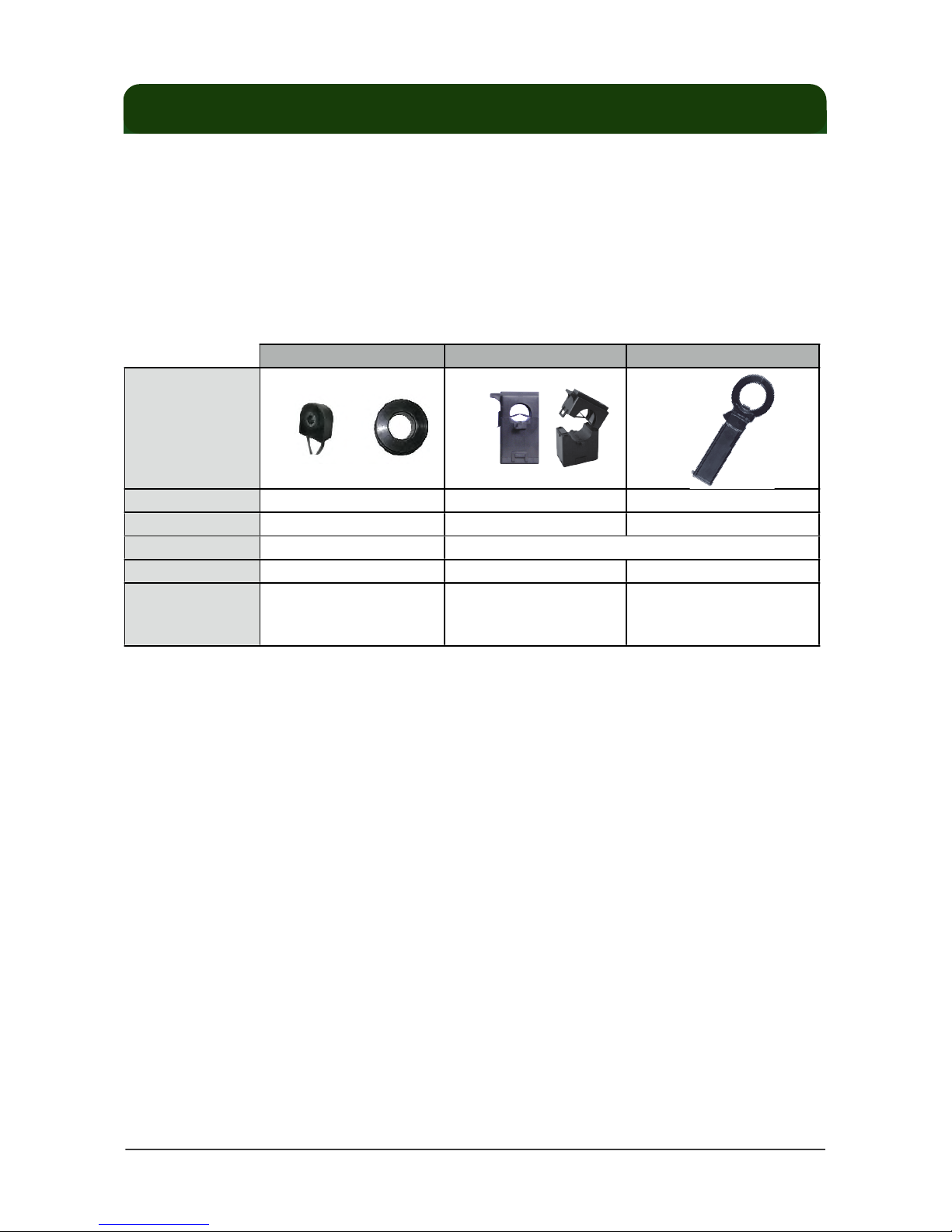
The measured current cannot be directly inputted into the Polaris. It requires external current transformers (CT), and
can be matched with a wide selection of dedicated CTs for current measurement values of 5A to 400A. The CTs are
available in solid core, split core or clamp type; each with its own advantages depending on requirements as shown in
the table below:
Solid Core
Split Core
Clamp Type
Appearance
Size
Cost
Installation
Available Ratings
Application
very small to small
small
medium
cheap to low
moderate
expensive
interrupts power
no power interruption
5A, 200A
5A, 50A, 100A, 200A
400A
permanent installation
permanent or semi-
permanent installation
temporary measurement or
when up to 400A current rating
is needed
The dedicated CTs for use with the Polaris is available only from DAE and needs to be preselected together with the
model during ordering. For installations with pre-existing CTs or if larger capacities is required, the user should choose
the dedicated 5A CT and connect the user provided CT to the dedicated 5A CT. See the section on using a standard 5A
output CT for details.
In addition to its basic measurement capability, it is also available with a variety of options for different applications
including RS485 communications interface, prepaid smart card reader, relay driver output, online prepaid capability,
customizable discrete input and output.
Its RS485 interface allows it to be read remotely as part of a simple auto meter reading system or even form the
basis of a comprehensive energy monitoring system.
The Polaris can also be used as a prepaid meter with the optional ICR815L smart card reader and an external relay;
it can even form the basis of an online prepaid metering and remote disconnection system with its online prepaid
capability.
The Polaris is also equipped with both a discrete input and output that can be used for special purpose applications
as part of a custom designed ODM model.
Polaris Userʼs Manual 1.3e" 2/11
Page 4
Installation
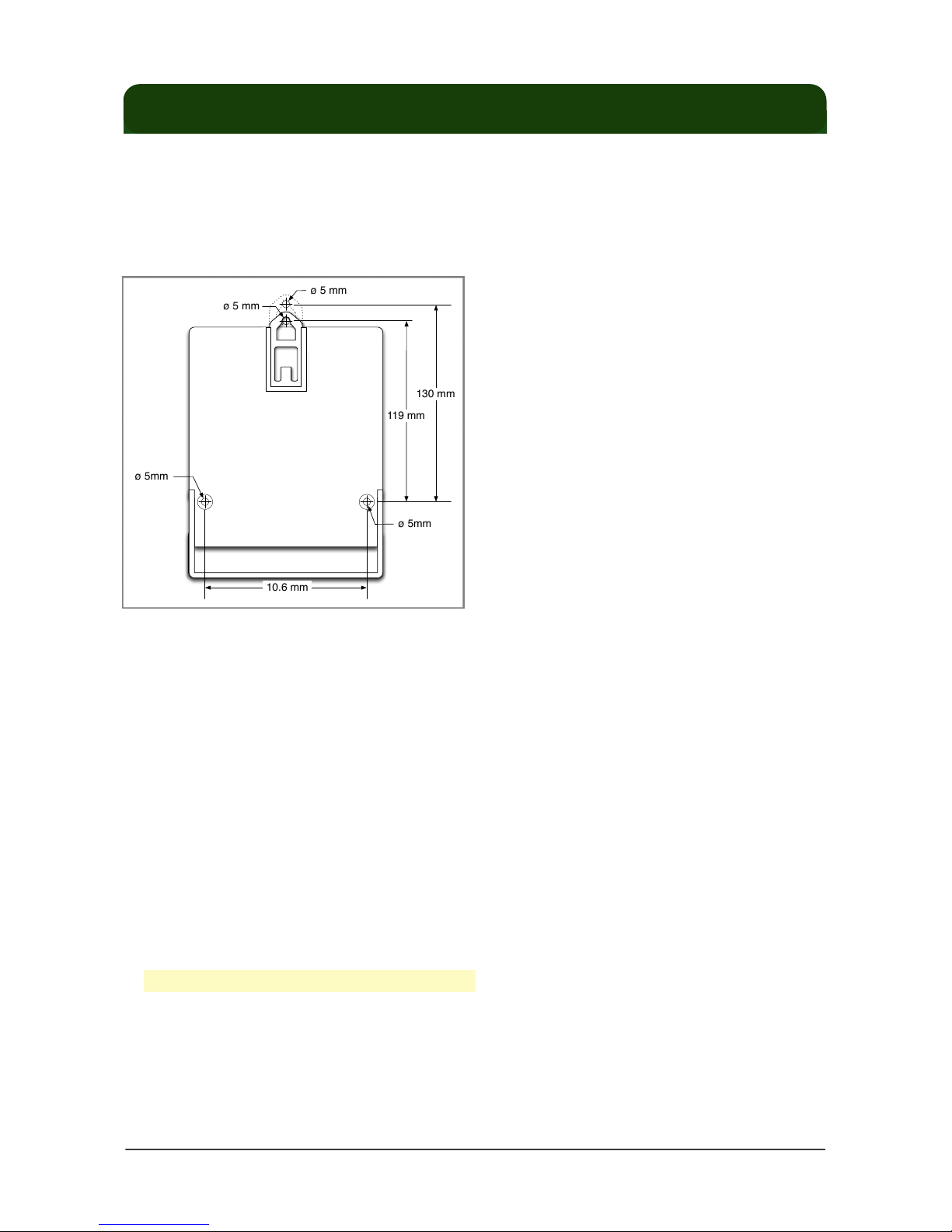
Mounting Procedure
1. The Polaris is wall mounted, drill the screw holes according to the diagram below.
2. Place the Polaris flush against the wall aligning the mount holes of the Polaris with the screw holes.
3. Secure the Polaris using the screws through the mount holes.
Mounting Dimensions
ø 5mm
10.6 mm
ø 5 mm
ø 5 mm
ø 5mm
119 mm
130 mm
Electrical Installation
The Polaris is a sophisticated energy meter with multiple capabilities and functions. Before installation be sure to read
and understand this section and the appropriate wiring diagrams. Installation of this device must be performed by
qualified personnel according to these instructions and in conjunction with all applicable electrical codes. DAE Instrument
and its representatives assumes no responsibility for any damage or injury resulting from the improper installation of this
equipment.
1. Check that the ratings and specification of the model to be installed is suitable for its intended application.
2. Verify that the dedicated CT being used is compatible with the type of Polaris. Note that the Polaris cannot be directly
used with non-DAE dedicated CTs. See the special application section for using the Polaris with common 5A output
CTs.
3. Verify that the current rating of the dedicated CT being used is suitable for its intended load.
4. Make sure to turn off all power sources to the Polaris and any adjacent power sources before performing the
installation.
5. Attach the dedicated CTs to their appropriate phases.
6. Connect the phase A voltage terminals of the Polaris to the corresponding power source with an intermediate 0.5A/
250V fuse.
7. Connect the voltage terminals of the Polaris to their corresponding phase voltages.
* Use 18 to 22 AWG, 600V wire for the voltage terminals.
8. Assemble the CTs onto the corresponding conductors being measured making sure that the direction and orientation
of the CTs with wiring are consistent. With solid core CTs, the wire must be threaded through the CT, which would
necessitate disconnecting the wire from the load. With split core CTs and clamp type CTs, the CT can be opened and
clipped or clamped onto the conductor without the need to disconnect the wiring to the load.
Polaris Userʼs Manual 1.3e" 3/11
Page 5

Electrical Wiring Diagrams
Polaris
VA VB VC VN IA+ IA- IB+ IB- IC+ IC-
K
L
L
N
Source
Load
1p2w
VLN ≤ 240V
A
B
N
Polaris
VA VB VC VN IA+ IA- IB+ IB- IC+ IC-
K
L
K
L
L1
L2
N
Source
Load
1p3w
VAN, V
BN
≤ 240V
A
B
N
Polaris
VA VB VC VN IA+ IA- IB+ IB- IC+ IC-
K
L
K
L
A
B
N
Source
Load
2p3w
VAN, V
BN
≤ 240V
A
B
Polaris
VA VB VC VN IA+ IA- IB+ IB- IC+ IC-
K
L
L1
L2
Source Load
3p2w
VAB, VBC, V
CA
≤ 240V
A
B
N
Polaris
VA VB VC VN IA+ IA- IB+ IB- IC+ IC-
K
L
K
L
A
B
N
Source Load
3p4w
c
C
VAN, VBN, V
CN
≤ 240V
K
L
Polaris Userʼs Manual 1.3e" 4/11
Page 6

Power Supply
The power supply of the Polaris is derived from the phase A voltage. To provide additional protection for the Polaris, a
0.5A/250V fuse should be placed between the Polaris and the power source as shown in each of the electrical wiring
diagrams.
Using a Regular 5A Output CT
For installations with pre-existing CTs or if larger capacities is required, the user should choose the dedicated 5A CT
and connect the user provided CT to the dedicated 5A CT as shown in the diagram below.
Connecting with a Regular 5A Output CT Wiring Diagram
CT
+ –
Dedicated CT 5A:mA
Standard CT 1000A:5A
Source Load
RS485 Installation
The RS485 can be optionally equipped with an RS485 communication port. This port can be used for connecting with
PC for remote reading.
Multiple Polaris units can be connected to the same RS485 network. All the positive terminals are to be connected
together using the same red conductor, and all the negative terminals are to be connected together to the same blue
wire. The shielding wire should be grounded to the panel or enclosure.
When connecting as a network, the RS485 wires should be daisy chained as shown in the diagram, it should not be
branched off or looped.
Since most modern computers have no built in RS485, a converter is necessary to convert the RS485 signals into
something the host computer can understand. Typically this converter can either be an RS485 to RS232 converter, with
the host computer needing to have built in RS232 port or expansion card; or for some computers with no expansion such
as a notebook computer, an alternative would be to use a commercially available RS485 to Ethernet converter.
Polaris Userʼs Manual 1.3e" 5/11
Page 7

RS485 Wiring Diagram
...
+ – S + – S
Converter
+ – S
Host Computer
Polaris
Polaris
Prepaid Smart Card
The Polaris is also optionally available with prepaid smart card capability and used as part of a prepaid smart card
system with the optional ICR815L smart card reader and an external relay.
Prepaid Smart Card Wiring Diagram
RJ11
RJ11
6P4C flat cable
RLY
+ -
Polaris
ICR815L
Relay
Source Load
L
N
Polaris Userʼs Manual 1.3e" 6/11
Page 8

Specifications
Terminals and Indicators
LED display
TX, RX
A, B, C
P
Load
DI
VA, VB, VC, VN
DO+, DO-
DI+, DI-
RLY+, RLY-
P+, P-
RS485+, RS485-, RS485-S
CT-A+, CT-A-
CT-B+, CT-B-
CT-C+, CT-C-
IC Card Reader Interface Port
Primary display for showing kwh and possible other parameters
RS485 communications transmit and receive activity indicator
A, B, C phase voltage inputs indicator
Meter constant, 1000 imp/kWh indicator
Load enabled indicator
Digital input indicator
Phase A, B, C and N voltages
Digital output signal, reserved
Digital input signal, reserved
Relay driver, 12VDC/100mA
Pulse output signal
RS485 communications port
Phase A CT input
Phase B CT input
Phase C CT input
Interface port for ICR815L IC card reader
Polaris Userʼs Manual 1.3e" 7/11
Page 9

Measured Parameters
Phase
Phase
Parameter
RST
Total
Current✓ ✓ ✓
Voltage✓ ✓ ✓
kW (real power)
✓ ✓ ✓ ✓
kWh (real energy)
✓ ✓ ✓ ✓
kVAr (reactive power)
✓
kVArh (reactive power)
✓
KVA (apparent power)
✓
Power Factor
✓ ✓ ✓ ✓
Technical and Physical
Phase/Wire
1p2w, 1p3w, 2p3w, 3p2w, 3p4w
Models
1 phase
3 phase
Input Voltage
Polaris-120-A, Polaris-120-B,
Polaris-120-C
120V~
208V~
Input Voltage
Polaris-240-A, Polaris-240-B,
Polaris-240-C
240V~
416V~
Input Current
Varies with dedicated CT
Frequency
60 Hz
Measurement Category
CAT III
Fuse
0.5A/250V
Power Supply
Derived from A phase
Power Consumption
7VA
Measured Parameters
Phase voltage, line voltage, current, kW, kWh, kVARh, pf
KWH display
6 digits, 0 to 99,999.9
Accuracy
0.5% not including external CT error
Operating Temperature
0~50˚C
Relative Humidity
0~95% non-condensing
Weight
690g
Communications
Interface
RS485
Protocol
Modbus/RTU
Address
1 to 254 (default is last 2 digits of serial number, 01~99 = 1~99, 00 = 100)
Baud Rate
1200, 2400, 4800, 9600 (default is 9600)
Data Format
8/n/1
* For additional information on communicating with the Polaris using Modbus, please refer to the document “Polaris
Modbus Reference.pdf” that can be found on our website.
Polaris Userʼs Manual 1.3e" 8/11
Page 10

Dimensions
128
164.4
33
59.9
13
25
12
14
23.5
6
* all dimensions in mm
Mounting Accessory
Polaris Userʼs Manual 1.3e" 9/11
Page 11

Ordering Information
Models
Polaris-V-CT
240
120
V
CT400CC
CT5D3, CT5S
CT100D3, CT200D3, CT50S, CT100S, CT200S
Compatible with
B
A
CT
Polaris-240-C
Polaris-240-B
Polaris-120-A
Models
Polaris-240-A
Polaris-120-C
Polaris-120-B
Selection Guide
The CTs are not included with the Polaris and must be ordered separately. To use the table below, first select the
phase/wire and voltage from the leftmost columns, then select the type of CT desired and the current rating from the
topmost column. The intersection of the two indicates the model required. The CT model is in parenthesis under the
current rating, while the number of CTs can be found on the left on the same row as the phase/wire and voltage selected.
CT Type / Current Rating (CT Model)
CT Type / Current Rating (CT Model)
CT Type / Current Rating (CT Model)
Phase/
Solid Core
Solid Core
Split Core
Split Core
Clamp Type
Phase/
Wire
Voltage
CTs
5A
(CT5D3)
100A
(CT100D3)
200A
(CT200D3)
5A
(CT5S)
50A
(CT50S)
100A
(CT100S)
200A
(CT200S)
400A
(CT400C)
1p2w
120V11p3w
120/240V
2
2p3w
120/208V
2
Polaris-120-A
Polaris-120-B
Polaris-120-A
Polaris-120-B
Polaris-120-B
Polaris-120-C
3p3w
208V
3
Polaris-120-A
Polaris-120-B
Polaris-120-A
Polaris-120-B
Polaris-120-B
Polaris-120-C
3p4w
120/208V
3
Polaris-120-A
Polaris-120-B
Polaris-120-A
Polaris-120-B
Polaris-120-B
Polaris-120-C
1p2w
240V12p3w
240/416V
2
Polaris-240-A
Polaris-240-B
Polaris-240-A
Polaris-240-B
Polaris-240-B
Polaris-240-C
3p4w
240/416V
3
Polaris-240-A
Polaris-240-B
Polaris-240-A
Polaris-240-B
Polaris-240-B
Polaris-240-C
Examples:
Requirement
Requirement
Selection
Selection
Example
Phase/Wire
Voltage
Current Rating
CT type
Polaris Model
CT Model
Number of CTs
1
3p4w
120/208V
200A
split core
Polaris-120-B
CT200S
3
2
1p2w
240V
100A
solid core
Polaris-240-B
CT100D3
1
Polaris Userʼs Manual 1.3e" 10/11
Page 12

DAE INSTRUMENT CORP.
5F, No.157 Xinhu 1st Road, Neihu District, Taipei City 114, Taiwan (R.O.C.)
Tel: +886-2-2793-6123 Fax: +886-2-2793-6150
info@daeinstrument.com
www.DAEinstrument.com
 Loading...