

Page 1

Polaris 9300/9300xi Diagnostic Instructions
WARN ING
FOR YOUR SAFETY - This product must be serviced by a contractor who is licensed and qualified in pool equipment by the
jurisdiction in which the product will be installed where such state or local requirements exists. In the event no such state or local
requirement exists, the installer or maintainer must be a professional with sufficient experience in pool equipment installation and
maintenance so that all of the instructions in this manual can be followed exactly. Before installing this product, read and follow
all warning notices and instructions that accompany this product. Failure to follow warning notices and instructions may result in
property damage, personal injury, or death. Improper installation and/or operation will void the warranty.
Improper installation and/or operation can create unwanted electrical hazard which can cause serious injury, property damage, or
death.
Connect unit to receptacle protected by a ground fault circuit interrupter (GFCI). Such a GFCI receptacle should be provided by
a qualified installer and should be tested on a routine basis. To test the GFCI, push the test button. The GFCI should interrupt
power. Push the reset button. Power should be restored. If the GFCI fails to operate in this manner, the GFCI is defective. If the
GFCI interrupts power to the pump without the test button being pushed, a ground current is flowing, indicating the possibility
of an electric shock. Do not use this product. Disconnect the cleaner and have the problem corrected by a qualified service
representative before using.
KEEP OUT OF REACH OF CHILDREN
1. Introduction
This document gives diagnostic testing instructions
for the 9300/9300xi Sport.
The instructions were written with safety as the
priority and must be followed exactly. Not following
the written procedure or taking shortcuts may
increase the risk of personal injury. Read through
the instructions completely before starting the
procedure.
2. Diagnostic Instructions
The customer must provide the following items to
perform the diagnostic testing:
• Control Unit
• Cleaner Head with Floating Cable
H0359300 Rev -
Future
Use
Press to
STOP the test
Figure 1. Polaris Quick Diagnostic Test Box
Press to START
9300 or 9300xi test
Page 2
Page 2
A. Testing Cleaner Head and Floating Cable
1. Set the cleaner head on a block of wood or some
object that allows the cleaner wheels to be elevated
from the surface.
2. Plug the Polaris Quick Diagnostic Test Box into a
GFCI protected outlet.
3. Connect the fl oating cable from the cleaner to the
test box (see Figure 2).
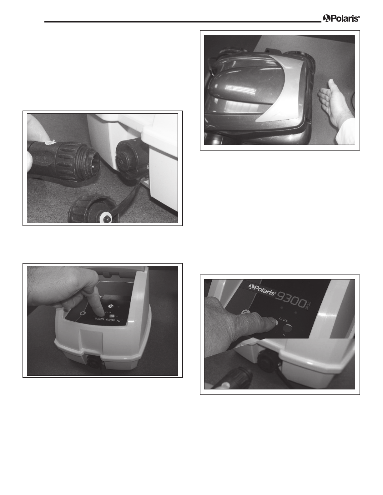
Figure 4. Checking for Air Flow
7. If the cycle completes without fl ashing lights, the
fl oating cable and cleaner head have successfully
passed the test.
Figure 2. Connect Floating Cable to Test Box
4. Determine the corresponding button for the model
being diagnosed (9300 or 9300xi). Press the button
to start the test (see Figure 3).
Figure 3. Select the Cleaner Model
8. If the diagnostic box fl ashes red lights at any
time during the test or the cleaner head does
not activate, proceed to Section C: Diagnosing a
Defective Motor Block or Floating Cable.
B. Testing the Control Unit
1. Reconnect the cleaner to the customer’s control
unit. Press the Cycle I button. (see Figure 5).
5. The pump motor should start fi rst. Check for air
fl owing from the exhaust on the back end of the
cleaner (see Figure 4).
6. Next, the drive motors should start within fi ve (5)
seconds after the pump motor starts. Take note
which direction the drive motors are rotating. The
drive motors drive the two (2) front wheels. Verify
that the two (2) front drive wheels move forward
then in reverse. After ten (10) seconds, all motors
should stop.
Figure 5. Testing the Control Unit
2. The drive cycle will turn on and will last for
approximately fi ve (5) seconds.
3. The cleaner will then drive forward for approximately
fi ve (5) seconds. If the cleaner does not drive
forward for approximately fi ve (5) seconds, then the
control unit is defective and must be replaced.
Page 3

Page 3
4. If the pump and drive motors drive, the control unit
has passed the test successfully. Turn off the power
to the control unit.
NOTE The control unit is programmed to shut down
power to the cleaner head within ten (10) seconds in order to protect the motor from damage.
C. Diagnosing a Defective Motor Block or
Floating Cable
1. Open the cleaner top and remove the fi lter canister.
Unthread the screw securing the prop guard in place
and remove the propeller guard (see Figure 6).
3. Close the cover and turn the cleaner over so that it’s
resting on its top.
4. Remove the four (4) screws from the bottom of the
cleaner. Remove the bottom plate/motor block
(see Figure 8).
Figure 8. Remove the Propeller Guard
Figure 6. Remove the Propeller Guard
2. Remove the propeller and the fl ow director
(see Figure 7).
5. Disconnect the fl oating power cable from the motor
block by removing the two screws connecting the
cable to the block, then pulling the plug away from
the block (see Figure 9).
Figure 9. Remove the Floating Cable
Figure 7. Remove the Propeller and Flow Director
Page 4

Page 4
6. Using the short test cable, connect the motor block to
the Polaris Quick Diagnostic Test Box (see Figure 10).
Figure 10. Motor Block Connected to Test Box
7. Once secured, start the diagnostic test (see Figure 11).
Figure 11. Testing the Motor Block
8. If the test completes without fl ashing red lights, then
the cable is defective. Replace the fl oating cable.
9. If the test ends with fl ashing red lights on the
diagnostic panel, then the motor block is defective.
Replace the motor block and return old motor to
Zodiac.
Zodiac Pool Systems, Inc.
2620 Commerce Way, Vista, CA 92081
1.800.822.7933 | www.ZodiacPoolSystems.com
All trademarks referenced herein are the property of their respective owners.
®
ZODIAC
is a registered trademark of Zodiac International, S.A.S.U., used under license.
©2011 Zodiac Pool Systems, Inc. H0359300 Rev - 1101
 Loading...