

Page 1

2009 Polaris Sportsman 850 EFi/HD/EPS series
Some models may need supplemental manuals which have blue titles. Use
the base manual for everything not contained in the supplement if your
model or year requires a supplement.
If you bought this manual from any other seller, they are reselling my
work.
Please leave them negative feedback & email me at
Our goal is to be one of the BEST sellers on eBay and the internet by
providing you with the BEST customer service and the BEST manuals on the
market.
.
Thank you for choosing us.
Page 2

GENERAL INFORMATION
CHAPTER 1
GENERAL INFORMATION
VEHICLE IDENTIFICATION . . . . . . . . . . . . . . . . . . . . . . . . . . . . . . . . . . . . . . . . . . . . . . . 1.2
MODEL IDENTIFICATION . . . . . . . . . . . . . . . . . . . . . . . . . . . . . . . . . . . . . . . . . . . . . . . .1.2
ENGINE DESIGNATION NUMBER . . . . . . . . . . . . . . . . . . . . . . . . . . . . . . . . . . . . . . . . .1.2
VEHICLE IDENTIFICATION NUMBER (VIN). . . . . . . . . . . . . . . . . . . . . . . . . . . . . . . . . .1.2
VEHICLE AND ENGINE SERIAL NUMBER LOCATIONS. . . . . . . . . . . . . . . . . . . . . . . .1.2
VEHICLE INFORMATION . . . . . . . . . . . . . . . . . . . . . . . . . . . . . . . . . . . . . . . . . . . . . . . . . 1.3
PUBLICATION NUMBERS. . . . . . . . . . . . . . . . . . . . . . . . . . . . . . . . . . . . . . . . . . . . . . . .1.3
REPLACEMENT KEYS . . . . . . . . . . . . . . . . . . . . . . . . . . . . . . . . . . . . . . . . . . . . . . . . . .1.3
SPECIAL TOOLS . . . . . . . . . . . . . . . . . . . . . . . . . . . . . . . . . . . . . . . . . . . . . . . . . . . . . . .1.3
SPECIFICATIONS. . . . . . . . . . . . . . . . . . . . . . . . . . . . . . . . . . . . . . . . . . . . . . . . . . . . . . . 1.4
GENERAL: 2009 SPORTSMAN XP 850 . . . . . . . . . . . . . . . . . . . . . . . . . . . . . . . . . . . . .1.4
GENERAL: 2009 SPORTSMAN XP 850 EPS . . . . . . . . . . . . . . . . . . . . . . . . . . . . . . . . .1.4
DETAILED: 2009 SPORTSMAN XP 850 / XP 850 EPS. . . . . . . . . . . . . . . . . . . . . . . . . .1.5
MISC. SPECIFICATIONS AND CHARTS . . . . . . . . . . . . . . . . . . . . . . . . . . . . . . . . . . . . . 1.6
CONVERSION TABLE. . . . . . . . . . . . . . . . . . . . . . . . . . . . . . . . . . . . . . . . . . . . . . . . . . .1.6
STANDARD TORQUE SPECIFICATIONS. . . . . . . . . . . . . . . . . . . . . . . . . . . . . . . . . . . .1.7
SAE TAP / DRILL SIZES . . . . . . . . . . . . . . . . . . . . . . . . . . . . . . . . . . . . . . . . . . . . . . . . .1 .8
METRIC TAP / DRILL SIZES . . . . . . . . . . . . . . . . . . . . . . . . . . . . . . . . . . . . . . . . . . . . . .1.8
DECIMAL EQUIVALENTS . . . . . . . . . . . . . . . . . . . . . . . . . . . . . . . . . . . . . . . . . . . . . . . .1.8
GLOSSARY OF TERMS. . . . . . . . . . . . . . . . . . . . . . . . . . . . . . . . . . . . . . . . . . . . . . . . . .1.9
1
1.1
Page 3

GENERAL INFORMATION
VEHICLE IDENTIFICATION
Model Identification
The machine model number must be used with any correspondence regarding warranty or service.
Machine Model Number Identification
Y ear Designation
Engine Designation Number
EH085OLE.............................................................Twin Cylinder, 4-Cycle SOHC, Liquid Cooled, Electric Start
V ehicle Identification Number (VIN)
World
Mfg. ID
1 2 3 4 5 6 7 8 9 10 11 12 13 14 15 16 17
4 X A Z N 8 5 A * 9 P 0 0 0 0 0 0
Vehicle Descriptor
A 0 9 Z N 8 5 A L
Basic Chassis
Designation
}
}
}
Engine Designation
}
}
Vehicle Identifier
Emissions &
Model Option
}
Body Style
V e hicle and Engine Serial Number Locations
Whenever corresponding about a Polaris ATV, be sure to refer to the vehicle identification number (VIN) and
the engine serial number.
The VIN can be found stamped on the lower frame rail on the front LH side of the ATV (see Figure 1-1).
The engine serial number can be found on top of the engine located on the valve cover (see Figure 1-2).
Figure 1-1
Engine
Powertrain
Emissions
Model
Year
Check Digit
Plant No
Figure 1-2
Individual Serial Number
* This could be either
a number or a letter
VIN
1.2
Engine Serial
Number
Page 4

GENERAL INFORMATION
VEHICLE INFORMATION
Publication Numbers
YEAR MODEL MODEL NO. OWNER’S MANUAL PN PARTS MANUAL PN
1
2009 SPORTSMAN XP 850
2009 SPORTSMAN XP 850 EPS
NOTE: Additional Polaris factory publications can be found at www.polarisindustries.com or purchased from
www.purepolaris.com.
A09ZN85AL, AQ,
AS, AT, AX, FL
A09ZX85AG, AL,
AQ, AR, AS, AX, FS
9921854 9921857
9921976 9921977
Replacement Keys
Replacement keys can be made from the original key. T o identify which series the key is, take the first two digits on the original key
and refer to the chart to the right for the proper part number. Should both keys become lost, replacement of the ignition switch
assembly is necessary.
KEY COVER
P/N 5533534
Key Series
Number
Series # Part Number
20 4010278
21 4010278
22 4010321
23 4010321
27 4010321
28 4010321
31 4110141
32 4110148
67 4010278
68 4010278
Special Tools
Special tools may be required while servicing this vehicle. Some of the tools listed or depicted are mandatory, while other tools
maybe substituted with a similar tool, if available. Polaris recommends the use of Polaris Special Tools when servicing any Polaris
product. Dealers may order special tools through Polaris’ official tool supplier, SPX Corporation, by phone at 1-800-328-6657 or
on-line at http://polaris.spx.com/
.
1.3
Page 5

GENERAL INFORMATION
SPECIFICATIONS
MODEL: 2009 SPORTSMAN XP 850
MODEL NUMBER:. . . . . . . . . A09ZN85AL, AQ, AS, AT, AX, FL
ENGINE MODEL:. . . . . . . . . . EH085OLE
Category Dimension
Length 83.25 in. / 211.5 cm
Width 47.6 in. / 121 cm
Height 50.75 in. / 129 cm
Wheel Base 53 in. / 135 cm
Ground Clearance 11.6 in. / 29.5 cm
Turning Radius 84 in. / 213 cm (unloaded)
Dry Weight 784 lbs. / 356 kg
Front Rack Capacity 120 lbs. / 54 kg
Rear Rack Capacity 240 lbs. / 109 kg
Max. Weight Capacity 575 lbs. / 261 kg
Towing Capacity 1500 lbs. / 680 kg
Hitch Tongue Weight 150 lbs. / 68 kg
MODEL: 2009 SPORTSMAN XP 850 EPS
MODEL NUMBER:. . . . . . . . . A09ZX85AG, AL, AQ, AR, AS, AX, FS
ENGINE MODEL:. . . . . . . . . . EH085OLE
Category Dimension
Length 83.25 in. / 211.5 cm
Width 47.6 in. / 121 cm
Height 50.75 in. / 129 cm
Wheel Base 53 in. / 135 cm
Ground Clearance 11.6 in. / 29.5 cm
Turning Radius 84 in. / 213 cm (unloaded)
Dry Weight 796 lbs. / 361 kg
Front Rack Capacity 120 lbs. / 54 kg
Rear Rack Capacity 240 lbs. / 109 kg
Max. Weight Capacity 575 lbs. / 261 kg
Towing Capacity 1500 lbs. / 680 kg
Hitch Tongue Weight 150 lbs. / 68 kg
1.4
Page 6
GENERAL INFORMATION
2009 SPORTSMAN XP 850 / XP 850 EPS
XP MODELS: A09ZN85AL,AQ,AS,AT,AX,FL
XP EPS MODELS: A09ZX85AG,AL,AQ,AR,AS,AX,FS
ENGINE MODEL: EH085OLE
Engine
Platform Domestic Twin Cylinder, 4-Cycle
Engine Model Number EH085OLE011
Engine Displacement 850 cc
Number of Cylinders 2
Bore & Stroke (mm) 87 x 71.5 mm
Compression Ratio 11.0:1
Compression Pressure 210 - 250 psi
Engine Idle Speed 1200
Cooling System / Cap. Liquid Cooled / 2 qt. (1.9 l)
Overheat Warning Instrument Cluster Indicator
Lubrication Pressurized Wet Sump
Engine Oil Requirement PS-4 Plus / 2 qt. (1.9 l)
Exhaust System
Fuel System Type
Throttle Body / Size Mikuni Dual Bore / 40 mm
Fuel Delivery
Fuel Pressure 43 psi
Fuel Capacity
Fuel Requirements 87 Octane (minimum)
Alternator Output 475 W @ 1200 RPM / Peak 575 W
Voltage Regulator 3-Phase / 32 Amp
Head Lights
Brake Light 12V / 27 Watts
Tail Light 12V / 7 Watts
Starting System Electric
Ignition System Bosch EFI (ECU Controlled)
Ignition Timing 6° ± 5° BTDC @ 1200 RPM
Spark plug / Gap REA8MCL / .035 in. (.90 mm)
Battery / Model / AH / CCA Deka / ETX30L / 30 AH / 365
Instrumentation Multifunction Instrument Cluster
DC Outlet Standard
Relays
(Located in Relay/Fuse Box)
Circuit Breaker Fan Motor: 20A
Fuses
(Located in Relay/Fuse Box)
Stainless Steel Dual Header Pipe
w/ Dual Outlet Silencer
Fuel System
Bosch Multi-Port Sequential
Electronic Fuel Injection
Electronic Fuel Pump
XP EPS: 4.5 gal. (17 l)
Electrical
Pod: 12V / 50 Watts
Bumper: 12V / 50 Watts x 2
Chassis / Start Solenoid / Fan /
EFI / Bumper Lights
Lights: 20A / Drive: 20A /
Accessory: 20A / EFI: 20A /
Unswitched: 10A / EPS: 30A
± 50 RPM
(in tank)
XP: 5.25 gal. (20 l)
Drivetrain
Transmission Type
Transmission
Fluid Type / Fluid Capacity
Front Gearcase
Fluid Type / Fluid Capacity
Front Gearcase
ADC Reservoir Fluid Type
Rear Gearcase
Fluid Type / Fluid Capacity
Clutch Type PVT w/EBS
Belt 3211123
Steering / Suspension
Toe Out 0-1/16 in. (0-.159 mm)
Front Suspension Dual A-arm
Front Travel 9.2 in. / 23.4 cm
Rear Suspension Dual A-arm w/Rolled IRS
Rear Travel 10.2 in. / 25.9 cm
Shock Preload Adjustment
Front / Rear
Wheels / Brakes
Front Wheel Size / Bolt Pattern
Tire Model / Size
Rear Wheel Size / Bolt Pattern
Tire Model / Size
Tire Air Pressure
Brakes - Front & Rear
Brake Fluid Polaris DOT 4 Brake Fluid
Automatic PVT
In-Line H-L-N-R-P
Synthetic Sportsman XP
Transmission Fluid /
32 oz. (946 ml)
Premium LT Demand Drive
Fluid / 9.3 oz. (275 ml)
Premium ADC
Front Drive Fluid
ATV Angle Drive Fluid /
7.1 oz. (210 ml)
Cam Adjustable
14 x 6 / 4-156
Carlisle T errathon / 26 x 8 - 14
14 x 8 / 4-156
Carlisle T errathon / 26 x 10 - 14
Front: 7 psi (48 kPa)
Rear: 5 psi (34.5 kPa)
Single Control
Hydraulic 4-Wheel Disc
CLUTCH CHART
Meters
(Feet)
Altitude
0-1800
(0-6000)
1800-3700
(6000 - 12000)
Shift
Weight
24-63
5632215
24-60
5632216
Drive
Spring
Red / Wht
7043349
Red / Wht
7043349
Driven
Spring
Red / Wht
3235621
Red / Wht
3235621
1
1.5
Page 7
GENERAL INFORMATION
MISC. SPECIFICATIONS AND CHARTS
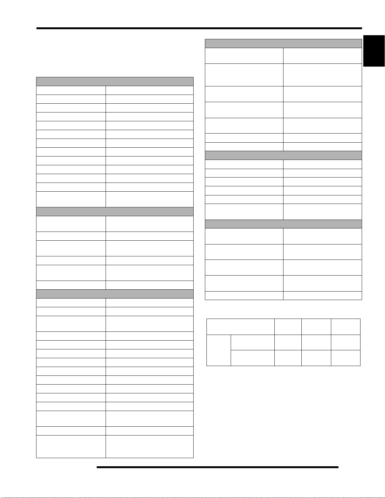
Conversion Table
°C to °F:
9/5
(°C + 32) = °F °F to °C:
1.6
5/9
(°F - 32) = °C
Page 8

GENERAL INFORMATION
Standard Torque Specifications
The following torque specifications are to be used only as a general guideline. There are exceptions in the
steering, suspension, and engine areas. Always consult the exploded views or each manual section for torque
values of fasteners before using standard torque.
1
1.7
Page 9

GENERAL INFORMATION
SAE Tap / Drill Sizes
Decimal Equivalents
Metric Tap / Drill Sizes
1.8
Page 10

GENERAL INFORMATION
Glossary of Terms
ABDC: After bottom dead center.
ACV: Alternating current voltage.
Alternator: Electrical generator producing voltage alternating current.
ATDC: After top dead center.
BBDC: Before bottom dead center.
BDC: Bottom dead center.
BTDC: Before top dead center.
CC: Cubic centimeters.
Center Distance: Distance between center of crankshaft and center of driven clutch shaft.
Chain Pitch: Distance between chain link pins (No. 35 = 3/8" or 1 cm). Polaris measures chain length in number of pitches.
CI: Cubic inches.
Clutch Buttons: Plastic bushings which aid rotation of the movable sheave in the drive and driven clutch.
Clutch Offset: Drive and driven clutches are offset so that drive belt will stay nearly straight as it moves along the clutch face.
Clutch Weights: Three levers in the drive clutch which relative to their weight, profile and engine RPM cause the drive clutch to
close and grip the drive belt.
Crankshaft Run-Out: Run-out or "bend" of crankshaft measured with a dial indicator while crankshaft is supported between centers
on V blocks or resting in crankcase. Measure at various points especially at PTO.
DCV: Direct current voltage
CVT: Centrifugal Variable Transmission (Drive Clutch System)
DCV: Direct current voltage.
Dial Bore Gauge: A cylinder measuring instrument which uses a dial indicator. Good for showing taper and out-of-round in the
cylinder bore.
Electrical Open: Open circuit. An electrical circuit which isn't complete.
Electrical Short: Short circuit. An electrical circuit which is completed before the current reaches the intended load. (i.e. a bare wire
touching the chassis).
End Seals: Rubber seals at each end of the crankshaft.
Engagement RPM: Engine RPM at which the drive clutch engages to make contact with the drive belt.
ft.: Foot/feet.
Foot Pound: Ft. lb. A force of one pound at the end of a lever one foot in length, applied in a rotational direction.
g: Gram. Unit of weight in the metric system.
gal.: Gallon.
ID: Inside diameter.
in.: Inch/inches.
Inch Pound: In. lb. 12 in. lbs. = 1 ft. lb.
kg/cm²: Kilograms per square centimeter.
kg-m: Kilogram meters.
Kilogram/meter: A force of one kilogram at the end of a lever one meter in length, applied in a rotational direction.
l or ltr: Liter.
lbs/in²: Pounds per square inch.
Left or Right Side: Always referred to based on normal operating position of the driver.
m: Meter/meters.
Mag: Magneto.
Magnetic Induction: As a conductor (coil) is moved through a magnetic field, a voltage will be generated in the windings.
Mechanical energy is converted to electrical energy in the stator.
mi.: Mi
mm: Millimeter. Unit of length in the metric system. 1 mm = approximately .040".
Nm: Newton meters.
OD: Outside diameter.
Ohm: The unit of electrical resistance opposing current flow.
oz.: Ounce/ounces.
Piston Clearance: Total distance between piston and cylinder wall.
psi.: Pounds per square inch.
PTO: Power take off.
PVT: Polaris Variable Transmission (Drive Clutch system)
qt.: Quart/quarts.
Regulator: Voltage regulator. Regulates battery charging system output at approx. 14.5 DCV as engine RPM increases.
Reservoir Tank: The fill tank in the liquid cooling system.
Resistance: In the mechanical sense, friction or load. In the electrical sense, ohms, resulting in energy conversion to heat.
RPM: Revolutions per minute.
Seized Piston: Galling of the sides of a piston. Usually there is a transfer of aluminum from the piston onto the cylinder wall.
Possible causes: 1) improper lubrication; 2) excessive temperatures; 3) insufficient piston clearance; 4) stuck piston rings.
Stator Plate: The plate mounted under the flywheel supporting the battery charging coils.
TDC: Top dead center. Piston's most outward travel from crankshaft.
Volt: The unit of measure for electrical pressure of electromotive force. Measured by a voltmeter in parallel with the circuit.
Watt: Unit of electrical power. Watts = amperes x volts.
WOT: Wide open throttle.
le/miles.
1
1.9
Page 11

GENERAL INFORMATION
NOTES
1.10
Page 12

MAINTENANCE
CHAPTER 2
MAINTENANCE
PERIODIC MAINTENANCE CHART. . . . . . . . . . . . . . . . . . . . . . . . . . . . . . . . . . . . . . . . . 2.2
BREAK-IN PERIOD / MAINTENANCE CHART KEY . . . . . . . . . . . . . . . . . . . . . . . . . . . .2.2
MAINTENANCE INTERVALS. . . . . . . . . . . . . . . . . . . . . . . . . . . . . . . . . . . . . . . . . . . . . .2.3
GREASE LUBRICATION POINTS . . . . . . . . . . . . . . . . . . . . . . . . . . . . . . . . . . . . . . . . . .2.5
MAINTENANCE QUICK REFERENCE . . . . . . . . . . . . . . . . . . . . . . . . . . . . . . . . . . . . . .2.6
MAINTENANCE QUICK REFERENCE, CONTINUED..... . . . . . . . . . . . . . . . . . . . . . . . .2.7
LUBRICANTS / SERVICE PRODUCTS . . . . . . . . . . . . . . . . . . . . . . . . . . . . . . . . . . . . . . 2.8
GENERAL VEHICLE INSPECTION AND MAINTENANCE. . . . . . . . . . . . . . . . . . . . . . . . 2.9
FUEL SYSTEM AND AIR INTAKE . . . . . . . . . . . . . . . . . . . . . . . . . . . . . . . . . . . . . . . . . . 2.9
FUEL LINES . . . . . . . . . . . . . . . . . . . . . . . . . . . . . . . . . . . . . . . . . . . . . . . . . . . . . . . . . . .2.9
FUEL FILTERS / VENT LINE. . . . . . . . . . . . . . . . . . . . . . . . . . . . . . . . . . . . . . . . . . . . .2.10
THROTTLE OPERATION / ETC SWITCH / THROTTLE CABLE ADJUSTMENT . . . . . 2.10
AIR FILTER / PRE-FILTER SERVICE . . . . . . . . . . . . . . . . . . . . . . . . . . . . . . . . . . . . . .2.11
ENGINE. . . . . . . . . . . . . . . . . . . . . . . . . . . . . . . . . . . . . . . . . . . . . . . . . . . . . . . . . . . . . . 2.12
ENGINE OIL LEVEL / OIL AND FILTER CHANGE . . . . . . . . . . . . . . . . . . . . . . . . . . . .2.12
ENGINE BREATHER HOSE / BREATHER ASSEMBLY . . . . . . . . . . . . . . . . . . . . . . . .2.13
VALVE CLEARANCE ADJUSTMENT . . . . . . . . . . . . . . . . . . . . . . . . . . . . . . . . . . . . . .2.14
COMPRESSION AND LEAKDOWN TESTS . . . . . . . . . . . . . . . . . . . . . . . . . . . . . . . . .2.15
EXHAUST SILENCER CLEANING. . . . . . . . . . . . . . . . . . . . . . . . . . . . . . . . . . . . . . . . .2.16
ENGINE MOUNT FASTENER TORQUE. . . . . . . . . . . . . . . . . . . . . . . . . . . . . . . . . . . .2.16
TRANSMISSION AND GEARCASES . . . . . . . . . . . . . . . . . . . . . . . . . . . . . . . . . . . . . . . 2.17
TRANSMISSION LUBRICATION. . . . . . . . . . . . . . . . . . . . . . . . . . . . . . . . . . . . . . . . . .2.17
FRONT GEARCASE LUBRICATION. . . . . . . . . . . . . . . . . . . . . . . . . . . . . . . . . . . . . . .2.18
FRONT GEARCASE ADC FLUID. . . . . . . . . . . . . . . . . . . . . . . . . . . . . . . . . . . . . . . . . .2.19
REAR GEARCASE LUBRICATION . . . . . . . . . . . . . . . . . . . . . . . . . . . . . . . . . . . . . . . .2.20
COOLING SYSTEM. . . . . . . . . . . . . . . . . . . . . . . . . . . . . . . . . . . . . . . . . . . . . . . . . . . . . 2.21
COOLANT LEVEL INSPECTION . . . . . . . . . . . . . . . . . . . . . . . . . . . . . . . . . . . . . . . . . .2.21
COOLING SYSTEM HOSES / COOLANT STRENGTH / COOLANT TYPE . . . . . . . . .2.22
PVT / FINAL DRIVE / WHEEL AND TIRE. . . . . . . . . . . . . . . . . . . . . . . . . . . . . . . . . . . . 2.23
PVT DRYING / DRIVE BELT REMOVAL. . . . . . . . . . . . . . . . . . . . . . . . . . . . . . . . . . . .2.23
DRIVE SHAFT BOOT INSPECTION . . . . . . . . . . . . . . . . . . . . . . . . . . . . . . . . . . . . . . .2.23
WHEEL AND HUB TORQUE TABLE. . . . . . . . . . . . . . . . . . . . . . . . . . . . . . . . . . . . . . .2.24
WHEEL REMOVAL / INSTALLATION . . . . . . . . . . . . . . . . . . . . . . . . . . . . . . . . . . . . . .2.24
TIRE PRESSURE / TIRE INSPECTION. . . . . . . . . . . . . . . . . . . . . . . . . . . . . . . . . . . . .2.25
ELECTRICAL AND IGNITION SYSTEM . . . . . . . . . . . . . . . . . . . . . . . . . . . . . . . . . . . . . 2.25
BATTERY MAINTENANCE . . . . . . . . . . . . . . . . . . . . . . . . . . . . . . . . . . . . . . . . . . . . . .2.25
BATTERY REMOVAL / INSTALLATION . . . . . . . . . . . . . . . . . . . . . . . . . . . . . . . . . . . .2.26
SPARK PLUG SERVICE . . . . . . . . . . . . . . . . . . . . . . . . . . . . . . . . . . . . . . . . . . . . . . . .2.26
ENGINE / CHASSIS GROUND . . . . . . . . . . . . . . . . . . . . . . . . . . . . . . . . . . . . . . . . . . .2.27
STEERING . . . . . . . . . . . . . . . . . . . . . . . . . . . . . . . . . . . . . . . . . . . . . . . . . . . . . . . . . . . 2.28
STEERING INSPECTION. . . . . . . . . . . . . . . . . . . . . . . . . . . . . . . . . . . . . . . . . . . . . . . .2.28
POWER STEERING UNIT (EPS MODELS). . . . . . . . . . . . . . . . . . . . . . . . . . . . . . . . . .2.28
TIE ROD END / STEERING INSPECTION / TOE ALIGNMENT . . . . . . . . . . . . . . . . . .2.29
TOE ALIGNMENT ADJUSTMENT. . . . . . . . . . . . . . . . . . . . . . . . . . . . . . . . . . . . . . . . .2.30
SUSPENSION . . . . . . . . . . . . . . . . . . . . . . . . . . . . . . . . . . . . . . . . . . . . . . . . . . . . . . . . . 2.30
SUSPENSION INSPECTION / SUSPENSION SPRING PRE-LOAD ADJUSTMENT . . 2.30
BRAKE SYSTEM. . . . . . . . . . . . . . . . . . . . . . . . . . . . . . . . . . . . . . . . . . . . . . . . . . . . . . . 2.31
BRAKE FLUID / BRAKE PAD / HOSE / FITTING INSPECTION . . . . . . . . . . . . . . . . . .2.31
AUXILIARY BRAKE PEDAL. . . . . . . . . . . . . . . . . . . . . . . . . . . . . . . . . . . . . . . . . . . . . .2.32
MAINTENANCE LOG . . . . . . . . . . . . . . . . . . . . . . . . . . . . . . . . . . . . . . . . . . . . . . . . . . . 2.33
2
2.1
Page 13

MAINTENANCE
PERIODIC MAINTENANCE CHART
Periodic Maintenance Overview
Inspection, adjustment and lubrication of important components are explained in the periodic maintenance chart.
Inspect, clean, lubricate, adjust and replace parts as necessary. When inspection reveals the need for replacement parts, use
genuine Pure Polaris parts available from your Polaris dealer.
NOTE: Service and adjustments are critical. If you’re not familiar with safe service and adjustment
procedures, have a qualified dealer perform these operations.
Maintenance intervals in the following chart are based upon average riding conditions and an average vehicle speed of approximately
10 miles per hour. Vehicles subjected to severe use must be inspected and serviced more frequently.
Severe Use Definition
• Frequent immersion in mud, water or sand
• Racing or race-style high RPM use
• Prolonged low speed, heavy load operation
• Extended idle
• Short trip cold weather operation
Pay special attention to the oil level. A rise in oil level during cold weather can indicate contaminants collecting in the oil sump or
crankcase. Change oil immediately if the oil level begins to rise. Monitor the oil level, and if it continues to rise, discontinue use
and determine the cause or see your dealer.
Break-In Period
The break-in period consists of the first 20 hours of operation. Careful treatment of a new engine and drive components will result
in more efficient performance and longer life for these components.
• Drive vehicle slowly at first while varying the throttle position. Do not operate at sustained idle.
• Pull only light loads.
• Perform regular checks on fluid levels and other areas outlined on the daily pre-ride inspection checklist.
• Change both the engine oil and filter after 20 hours or one month.
• See “Owner’s Manual” for additional break-in information.
Maintenance Chart Key
The following symbols denote potential items to be aware of during maintenance:
= CAUTION: Due to the nature of these adjustments, it is recommended this service be performed by an
authorized Polaris dealer.
= SEVERE USE ITEM: See information provided above.
E = Emission Control System Service (California).
NOTE: Inspection may reveal the need for replacement parts. Always use genuine Polaris parts.
WARNING
Improperly performing the procedures marked could result in component failure and lead to serious injury or death.
Have an authorized Polaris dealer perform these services.
2.2
Page 14

Maintenance Intervals
Maintenance Interval
Item
Hours Calendar
Steering - Pre-Ride -
Front Suspension - Pre-Ride -
Rear Suspension - Pre-Ride -
Tires - Pre-Ride Brake Fluid Level - Pre-Ride -
Brake Lever Travel - Pre-Ride -
Brake System - Pre-Ride Wheels / Fasteners - Pre-Ride Frame Fasteners - Pre-Ride Engine Oil Level - Pre-Ride -
Air Filter, Pre-filter - Daily - Inspect;clean often
E
Coolant - Daily -
(whichever comes first)
Miles
(KM)
Inspect and make adjustments as needed.
See Pre-Ride Checklist later in this chapter.
Check level daily, change coolant every two
years
MAINTENANCE
Remarks
2
ADC Fluid - Daily - Check level daily, add as needed
Power Steering Unit
(if equipped)
Head Lights / Tail Lights - Daily -
Air Filter (main element) - Weekly - Inspect; replace as needed
E
Brake Pad Wear 10 H Monthly 100 (160) Inspect periodically
Battery 20 H Monthly 200 (320) Check terminals; clean; test
Engine Oil Change
(Break-in Period)
E
Front Gearcase Fluid 25 H Monthly 250 (400) Inspect level
Rear Gearcase Fluid 25 H Monthly 250 (400) Inspect level
Transmission Fluid 25 H Monthly 250 (400) Inspect level
- Daily - Inspect daily, clean often
Check operation; apply dielectric grease if
replacing
20 H 1 M -
Perform a break-in oil change at one mont h or
20 hours, whichever comes first
Perform these procedures more often for vehicles subjected to severe use.
E Emission Control System Service (California)
Have an authorized Polaris dealer perform these services.
2.3
Page 15

MAINTENANCE
Maintenance Interval
Item
Hours Calendar
General Lubrication 50 H 3 M 500 (800) Lubricate all fittings, pivots, cables, etc.
Throttle Cable /
E
ETC Switch
Throttle Body Intake
E
Duct
Drive belt 50 H 6 M 500 (800) Inspect; replace as needed
Cooling System 50 H 6 M 500 (800)
Radiator 50 H 6 M 500 (800) Inspect; clean external surfaces
Cooling Hoses 50 H 6 M 500 (800) Inspect for leaks
Engine Oil Change 100 H 6 M 1000 (1600)
Oil Filter Change 100 H 6 M 1000 (1600) Replace with oil change
50 H 6 M 500 (800)
50 H 6 M 500 (800) Inspect ducts for proper sealing / air leaks
(whichever comes first)
Miles
Remarks
(KM)
Inspect; adjust; lubricate; replace if
necessary
Inspect coolant strength seasonally;
pressure test system yearly
Perform a break-in oil change at 20 hours or
after one month of operation; change more
frequently during cold weather operation
Front Gearcase Fluid - 12 M 1000 (1600) Change Fluid
Rear Gearcase Fluid - 12 M 1000 (1600) Change Fluid
Transmission Fluid - 12 M 1000 (1600) Change Fluid
Fuel System 100 H 12 M 1000 (1600)
E
Engine Mounts 100 H 12 M 1000 (1600) I nspect
Exhaust Pipe / Silencer 100 H 12 M 1000 (1600) Inspect
Sp ark Plug 100 H 12 M 1000 (1600) Inspect; replace as needed
E
Wiring 100 H 12 M 1000 (1600)
Clutches
(Drive and Driven)
Front Wheel Bearings 100 H 12 M 1000 (1600) Inspect; replace as needed
Brake Fluid 200 H 24 M 2000 (3200) Change every two ye ars
ADC Fluid 200 H 24 M 2000 (3200) Change every two years
Spark Arrestor
(if applicable)
Valve Clearance 1000 H - 10000 (16000) Inspect; adjust
E
Toe Adjustment - Inspect periodically; adjust as needed
Headlight Aim - Adjust as needed
100 H 12 M 1000 (1600) Inspect; clean; replace worn parts
300 H 36 M 3000 (4800) Clean out; or remove clean out plug
Check for leaks at tank cap, fuel lines, fuel
pump; replace lines every two years
Inspect for wear, routing, security; apply
dielectric grease to connectors subjected to
water, mud, etc.
Perform these procedures more often for vehicles subjected to severe use.
E Emission Control System Service (California)
Have an authorized Polaris dealer perform these services.
2.4
Page 16
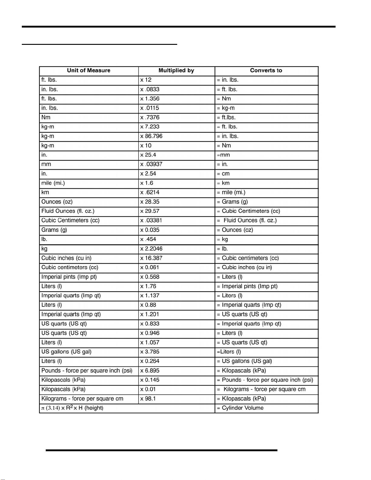
MAINTENANCE
Grease Lubrication Points
There are grease fittings on each upper and lower front and rear A-arms, each rear bearing carrier, and on the front propshaft yoke.
Apply a maximum of 3 pumps of grease at each of these areas.
Item Recommended Lube Method Frequency
Front Propshaft Yoke
Front & Rear A-Arms
Rear Bearing Carrier
Polaris Premium U-Joint Grease
Grease fittings
(3 pumps maximum)
every 500 miles (800 km).
Grease before long periods
2
of storage, and after
pressure washing or
submerging the ATV.
2.5
Page 17
MAINTENANCE
Maintenance Quick Reference
III. # Item Lube Rec. Method Frequency*
Change after 1st month or first
20 hours of operation, 100
Engine Oil Polaris PS-4 PLUS 2W-50
1
Performance Synthetic
Add oil to proper level on
dipstick
hours thereafter; Change more
often (25 hours) in severe duty
conditions or short trip cold
weather operation
2 Transmission
3 Engine Coolant Polaris 60/40 Coolant
* More often under severe use, such as operated in water or under severe loads.
Synthetic Sportsman XP
Transmission Fluid
Add fluid until it is visible at
the fill hole threads
Maintain coolant level in
coolant reservoir bottle.
Check level every 25 hours;
change fluid yearly
Check level daily, change
coolant every 2 years
2.6
Page 18

MAINTENANCE
Maintenance Quick Reference, Continued.....
III. # Item Lube Rec. Method Frequency*
Front Gearcase
4
ADC Reservoir
5 Front Gearcase
6 Rear Gearcase
7 Brake Fluid Polaris DOT 4 Brake Fluid
* More often under severe use, such as operated in water or under severe loads.
Polaris Premium ADC
Front Drive Fluid
Polaris Premium LT
Demand Drive Fluid
Polaris ATV Angle Drive
Fluid (ADF)
Maintain fluid level in ADC
Reservoir to indicated level
Add fluid until it is visible at
the fill hole threads
Add fluid until it is visible at
the fill hole threads
Maintain fluid level in both
master cylinder reservoirs to
indicated levels
Check level every 25 hours;
change fluid every two years
Check level every 25 hours;
change fluid yearly or 1000 mi.
Check level every 25 hours;
change fluid yearly
Check level during pre-ride
inspection; change fluid every
two years
2
2.7
Page 19
MAINTENANCE
LUBRICANTS / SERVICE PRODUCTS
Polaris Lubricants,Maintenance and Service
Products
Part No. Description
Engine / Transmission Lubricant
2870791 Fogging Oil (12 oz. Aerosol)
2876244
2876245
2877606
2876251
2872277
2876160
2872276
2870465 Pump for Gallon Jug
2871534 60/40 Coolant (Quart) (12 count)
2871323 60/40 Coolant (Gallon) (6 count)
2871312 Grease Gun Kit
2871322
PS-4 PLUS 2W-50 Performance Synthetic
4-Cycle Engine Oil (Quart)
PS-4 PLUS 2W-50 Performance Synthetic
4-Cycle Engine Oil (Gallon)
Gearcase Lubricants
Synthetic Sportsman XP
Transmission Fluid (Quart)
Premium LT Demand Drive Fluid
(Quart) (12 count)
Premium Demand Drive Hub Fluid
(2.5 Gallon) (2 count)
ATV Angle Drive Fluid
(Quart) (12 count)
ATV Angle Drive Fluid
(2.5 Gallon) (2 Count)
Coolant
Grease / Specialized Lubricants
Premium All Season Grease
(3 oz. cartridge) (24 Count)
Additives / Sealants / Thread Locking Agent s / Misc.
2870585 Loctite™ Primer N, Aerosol, 25 g
2871956
2871949
2871950
2871951
2871952
2871953
2871954
2870584
2870587
2871326
2870652 Fuel Stabilizer (16 oz.) (12 Count)
2872189 DOT 4 Brake Fluid (12 Count)
2871557 Crankcase Sealant, 3-Bond 1215 (5oz.)
2872893 Engine Degreaser (12oz.) (12 Count)
NOTE: The number count indicated by each part
number in the table above indicates the number of
units that are shipped with each order.
Loctite™ Thread Sealant 565
(50 ml.) (6 Count)
Loctite™ Threadlock 242
(50 ml.) (10 Count)
Loctite™ Threadlock 242
(6 ml.) (12 Count)
Loctite™ Threadlock 262
(50 ml.) (10 Count)
Loctite™ Threadlock 262
(6 ml.) (12 Count)
Loctite™ Threadlock 271
(6 ml.) (12 Count)
Loctite™ Threadlock 271
(36 ml.) (6 Count)
Loctite™ 680-Retaining Compound
(10 ml.)
Loctite™ 518 Gasket Eliminator / Flange
Sealant (50 ml.) (10 Count)
Premium Carbon Clean
(12 oz.) (12 Count)
2871423
2871460 Starter Drive Grease (12 Count)
2871515 Premium U-Joint Lube (3 oz.) (24 Count)
2871551 Premium U-Joint Lube (14 oz.) (10 Count)
2871329 Dielectric Grease (Nyogel™)
NOTE: Each item can be purchased separately at
your local Polaris dealer.
Premium All Season Grease
(14 oz. cartridge) (10 Count)
2.8
Page 20

MAINTENANCE
GENERAL VEHICLE INSPECTION
AND MAINTENANCE
Pre-ride / Daily Inspection
Perform the following pre-ride inspection daily, and when
servicing the vehicle at each scheduled maintenance.
• Tires - check condition and tire pressure
• Fuel and oil - fill both to their proper level; do not
overfill
• All brakes - check operation (includes auxiliary brake)
• Throttle - check for free operation
• Headlight / Taillight / Brakelight - check operation of
all indicator lights and switches
• Engine stop switch (key switch) - check for proper
function
• Wheels - check for loose wheel nuts
• Air cleaner element - check for dirt or water; clean or
replace
• Steering - check for free operation, noting any unusual
looseness in any area
• Loose parts - visually inspect vehicle for any damaged
or loose nuts, bolts or other fasteners
• Engine coolant - check for proper level at the recovery
bottle
FUEL SYSTEM AND AIR INTAKE
Fuel System
WARNING
2
Gasoline is extremely flammable and explosive
under certain conditions.
• Always stop the engine and refuel outdoors or in a well
ventilated area.
• Do not smoke or allow open flames or sparks in or near
the area where refueling is performed or where gasoline
is stored.
• Do not overfill the tank. Do not fill the tank neck.
• If you get gasoline in your eyes or if you swallow
gasoline, seek medical attention immediately .
• If you spill gasoline on your skin or clothing,
immediately wash it off with soap and water and
change clothing.
• Never start the engine or let it run in an enclosed area.
Engine exhaust fumes are poisonous and can result loss
of consciousness or death in a short time.
• Never drain the fuel when the engine is hot. Severe
burns may result.
Frame, Nuts, Bolts, Fasteners
Periodically inspect the torque of all fasteners in accordance
with the maintenance schedule. Check that all cotter pins are in
place. Refer to specific fastener torques listed in each chapter.
Controls
Check handlebar controls for proper operation, positioning and
adjustment.
Fuel Lines
1. Check fuel lines for signs of wear, deterioration, damage,
or leakage. Replace if necessary.
2. Be sure fuel lines are routed properly and secured with
cable ties where applicable.
CAUTION
Make sure lines are not kinked or pinched
3. Replace all fuel lines every two years.
2.9
Page 21
MAINTENANCE
Fuel Filters
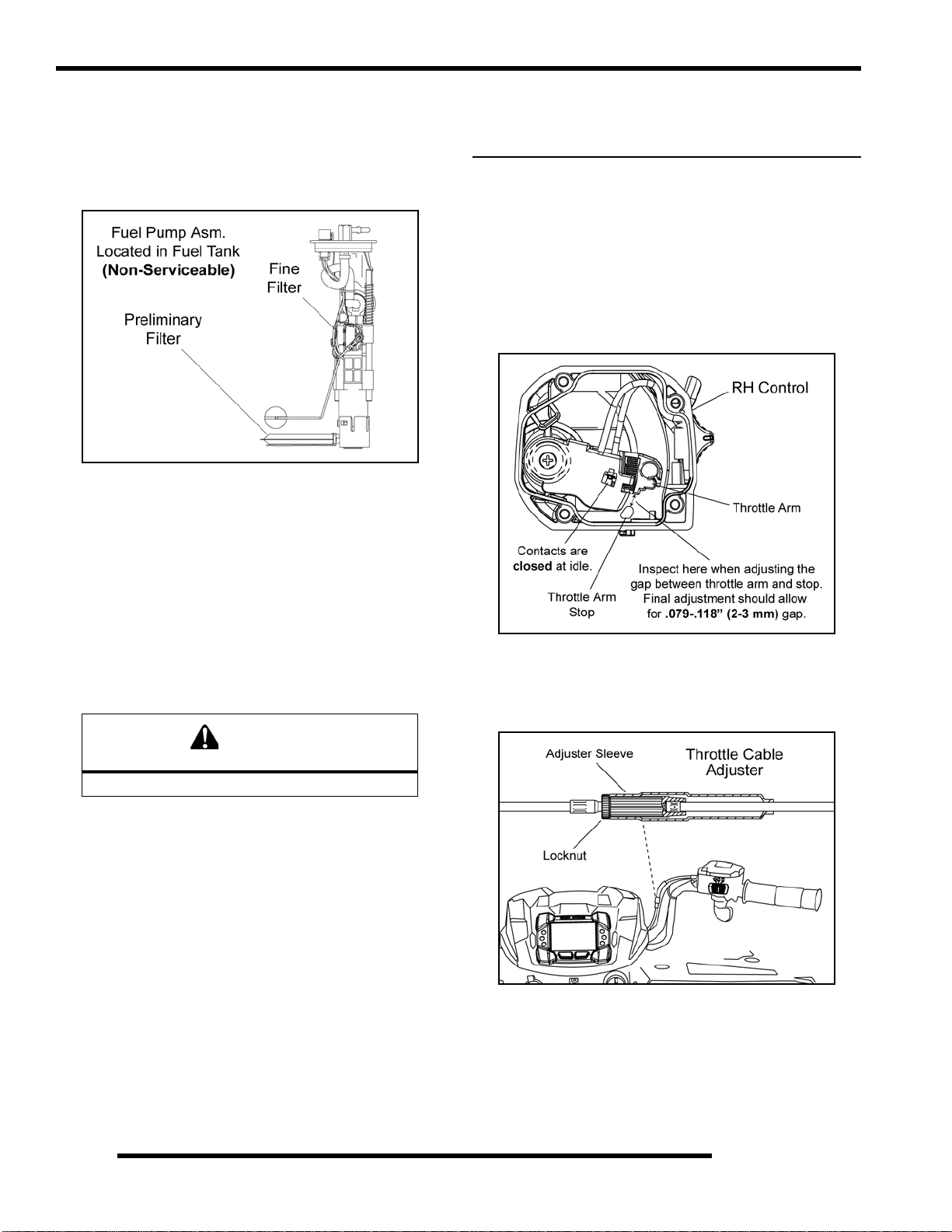
There are two fuel filters located within the fuel pump assembly.
The fuel pump is non-serviceable. If the internal fuel pump
filters require service, the fuel pump and fuel tank must be
replaced as an assembly.
NOTE: See the “Electronic Parts Catalog” for more
information. For all other information related to the EFI
System, refer to Chapter 3.
Electronic Throttle Control Switch (ETC) /
Throttle Cable Adjustment
NOTE: Sportsman XP requires a new adjustment procedure.
1. Slide the boot back far enough to expose the inline cab le
adjuster sleeve and loosen the adjuster locknut.
2. Remove the (4) screws and cover from the RH control.
3. With handlebars centered and wheels pointing forward,
slowly turn the adjuster sleeve counter-clockwise (out) just
until the gap is removed between the throttle arm and the
throttle arm stop (see illustration below).
NOTE: While moving the adjuster sleeve, “flip” the
throttle lever slightly to remove slack in the cable.
Vent Line
1. Check the vent line from the fuel tank for signs of wear,
deterioration, damage or leakage. Replace the line every
two years.
2. Verify vent line is routed properly and secured with an
appropriate number of cable ties.
CAUTION
Make sure lines are not kinked or pinched
Throttle Operation
Check for smooth throttle opening and closing in all handlebar
positions. Throttle lever operation should be smooth and lever
must return freely without binding.
1. Place the gear selector in neutral.
2. Set parking brake.
3. Start the engine and let it idle.
4. Turn handlebars from full right to full left. If i dle speed
increases at any point in the turning range, inspect throttle
cable routing and condition. If cable is routed properly and
in good condition, no adjustment is required.
5. Replace the throttle cable if worn, kinked, or damaged.
4. Turn the cable adjuster sleeve clockwise (in) 1.5 - 2 turns;
tighten locknut and reinstall boot. After this adjustment
there should be .079-.118” (2-3 mm) gap between thrott le
arm and throttle arm stop.
5. Reinstall the RH control cover and ensure the O-ring is
properly in place. Securely tighten the (4) screws.
6. Place the vehicle in PARK and start the engine. Turn the
handlebars from full left to full right while listening for any
change in engine speed. If engine speed changes, loosen
the locknut and turn the adjuster sleeve clockwise (in) an
additional 1/2 turn and repeat this step.
2.10
Page 22

MAINTENANCE
Air Filter / Pre-Filter Service
It is advisable to replace the filter when it is dirty . However, in
an emergency, it is permissible to clean the main filter if you
observe the following practices.
• Never immerse the filter in water since dirt can be
transferred to the clean air side of the filter.
• If compressed air is used never exceed a pressure of 40
PSI. Always use a dispersion type nozzle to prevent
filter damage and clean from the inside to the outside.
It is recommended that the air filter and pre filter be replaced
annually. When riding in extremely dusty conditions,
replacement is required more often.
Removal:
1. Remove the seat to access the airbox cover.
Cleaning:
4. Slip the pre-filter screen off of main element. Clean the prefilter with hot soapy water.
5. Rinse and dry thoroughly.
6. Inspect pre-filter screen for tears or damage.
7. Inspect main filter and replace if necessary. If the filter has
been soaked with fuel or oil it must be replaced.
Installation:
8. Inspect airbox cover seal for damage. It should adhere
tightly to the cover and seal all the way around. Replace
seal as needed.
9. Reinstall pre-filter screen over main filter. Be sure the
screen covers entire surface of main filter without folds,
creases, or gaps.
NOTE: Apply a small amount of general purpose grease
to the sealing edges of the filter before reinstalling.
10. Install air filter assembly into the airbox and position it
correctly before closing the airbox cover.
2
2. Unscrew the two knobs retaining the airbox cover and open
the cover.
NOTE: Proper placement of the air filter is important to
prevent air leaks.
11. Close airbox cover and secure cover by tightening the
retaining knobs.
12. Check the intake boot for cracks, deterioration, abrasion, or
leaks. Replace as needed.
3. Remove the air filter assembly from the airbox.
2.11
Page 23

MAINTENANCE
ENGINE
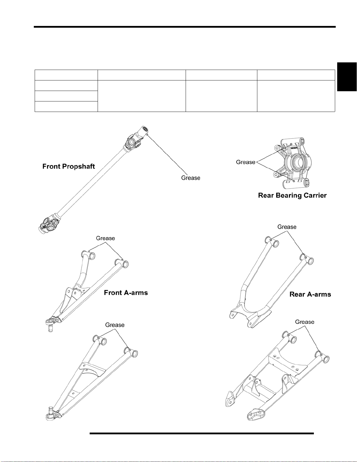
Engine Oil Level
Polaris recommends the use of Polaris PS-4 PLUS synthetic
engine oil. Always use PS-4 PLUS engine oil. Oil may need to
be changed more frequently if Polaris engine oil is not used.
CAUTION
Mixing brands or using a non-recommended
engine oil may cause serious engine damage.
Always use the recommended engine oil. Never
substitute or mix engine oil brands.
1. Locate the engine oil dipstick on the left side of the ATV.
Engine Oil and Filter Change
Always change engine oil and filter at the intervals outlined in
the Periodic Maintenance Chart. Always change the oil filter
whenever changing the engine oil.
1. Position the ATV on a level surface.
2. Place the transmission in park.
3. Start engine and allow it to run for two to three minutes until
the engine is warm.
4. Stop the engine.
5. Clean the area around the drain plug.
2. Position the ATV on a level surface.
3. Stop engine and remove the dipstick. Wipe i t dry with a
clean cloth.
4. Reinstall and tighten the dipstick.
NOTE: The dipstick must be screwed in completely
to ensure an accurate measurement.
5. Remove the dipstick and check the oil level.
6. Maintain the oil level in the safe range. Do not overfill.
6. Place a drain pan beneath the engine crankcase.
7. Using a 6 mm Hex socket, remove the drain plug and allow
the engine oil to drain completely.
WARNING
Hot oil can cause serious burns to skin.
Do not allow hot oil to contact skin.
8. Replace the sealing washer on the drain plug.
2.12
Page 24

MAINTENANCE
NOTE: The sealing surfaces on the drain plug and
crankcase should be clean and free of burrs, nicks
or scratches.
9. Reinstall drain plug and torque to 12 ft. lbs. (16 Nm).
= T
Engine Drain Plug: 12 ft. lbs. (16 Nm)
10. Locate oil filter through access hole in the skid plate. Place
shop towels beneath the oil filter. Using oil filter wrench
(PV-43527) turn oil filter counterclockwise to remove it.
16. Stop the engine and check for leaks.
17. Re-check the oil level on the dipstick and add oil as
necessary to bring the level to the upper mark on the
dipstick.
18. Dispose of used oil and filter properly.
2
Engine Breather Hose
Be sure engine breather hose is routed properly and secured in
place. CAUTION: Make sure line is not kinked or pinched.
Breather
Inspect
Airbox
11. Use a clean dry towel to clean the filter sealing surface on
the crankcase.
12. Check to make sure the O-ring on the new oil filt er is in
good condition. Lubricate O-ring on new filter with a film
of fresh engine oil.
13. Install new oil filter and turn by hand until filter gasket
contacts the sealing surface, then turn it and additional 1/2
turn.
= T
Oil Filter Torque:
Turn by hand until filter gasket contacts sealing
surface, then turn an additional 1/2 turn.
14. Remove dipstick and fill engine with 1.75 qts. (1.66 L) of
the recommended engine oil.
=
Recommended Engine Oil:
Engine Breather Assembly
The engine breather assembly is located on top of the valve
cover. Inspect and service the breather components as required.
PS-4 PLUS Synthetic 4-Cycle Engine Oil
(PN 2876244) (Quart)
15. Start the engine and allow it to idle for one to two minutes.
2.13
Page 25

MAINTENANCE
Valve Clearance Adjustment
1. Remove the seat and both upper side panels.
2. Disconnect the shift linkage from the shift lever.
3. Remove the (2) screws retaining the lower portion of the
air box.
4. Remove the hose from the breaker valve located on top of
the valve cover.
5. Remove the push rivets retaining the right-hand portion of
the rear cab to gain access to the bolts retaining the upper
right-hand frame support.
6. Remove the (4) bolts retaining the frame support. Pull the
support forward and down to remove it from the vehicle.
7. Remove the (2) Torx-head screws retaining the upper
portion of the air box to the front cab.
8. Carefully disconnect the ECU by pulling the tab out while
pulling down on the connector.
9. Loosen the hose clamp retaining the intake boot to the
intake plenum and remove the boot.
10. Lift up on the air box and turn it sideways to gain access to
the valve cover bolts.
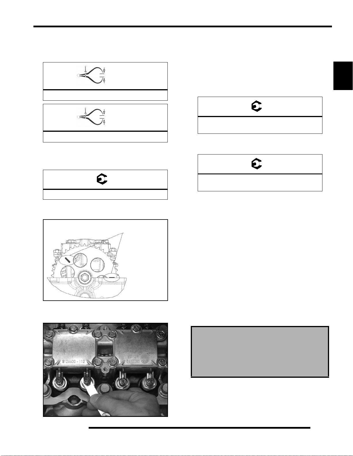
MAG & PTO ADJUSTMENT PROCEDURE
14. Turn the drive clutch counter-clockwise until the cam
sprocket is in the MAG (#1) Adjustment Position.
MAG (#1)
Adjustment Position
Timing Pin in Vertical Position
TDC #1 (MAG) Cylinder
11. Remove the spark plug wires and spark plugs.
12. Remove the (6) valve cover bolts and valve cover.
13. Remove PVT cover so the engine can be rotated (see “Drive
Belt Removal” procedure within this chapter).
Timing Marks Lined Up With Top of Head
at MAG (#1) Adjustment Position
15. Set the MAG cylinder valve lash by placing the feeler gauge
blade between the lash adjuster and valve as shown.
2.14
MAG (#1)
Page 26
MAINTENANCE
16. Loosen the jam nut and turn the lash adjuster until the valve
lash is correct.
17. Set the intake and exhaust valve lash to specification.
= In. / mm.
Intake Valve Clearance: .006 in. (.15 mm)
= In. / mm.
Exhaust Valve Clearance: .009 in. (.23 mm)
18. Hold adjuster and torque the jam nut using a torque wrench
w/10 mm crow’s foot adaptor. Verify clearance is still
correct after tightening the jam nut.
= T
Rocker Jam Nut: 71-89 in. lbs. (8-10 Nm)
19. Turn the drive clutch counter-clockwise to rotate the cam
sprocket 225° to the PTO (#2) Adjustment Position.
21. Repeat steps 16-18.
22. Clean sealing surfaces of the cylinder head and valve cover.
23. Inspect the condition of the valve cover bolt rubber
isolators. If rubber has become hardened or cracked,
replace them.
24. Install a new valve cover seal and install the valve cover.
Torque the cover bolts to specification.
= T
Valve Cover Bolts:
89 in. lbs. (10 Nm)
25. Install the upper right-hand frame support and torque the
(4) mounting bolts to specification.
= T
Upper Right-Hand Frame Support Bolts:
36 ft. lbs. (49 Nm)
26. Reassemble vehicle by reversing this procedure. Start the
engine to ensure proper valve adjustment was performed.
2
PTO (#2)
Adjustment Position
20. Set the PTO cylinder valve lash by placing the feeler gauge
blade between the lash adjuster and valve as shown.
Timing Marks at PTO (#2)
Adjustment Position
PTO (#2)
Compression and Leakdown Tests
NOTE: This engine does NOT have decompression
components. Compression readings will vary in
proportion to cranking speed during the test.
Smooth idle generally indicates good compression. Low engine
compression is rarely a factor in running condition problems
above idle speed. Abnormally high compression can be caused
by worn or damaged exhaust cam lobes.
A cylinder leak-down test is the best indication of engine
condition. Follow tester manufacturer’s instructions to perform
a cylinder leak-down test. (Never use high pressure leakage
testers as crankshaft seals may dislodge and leak).
Measured Cylinder Compression
210-250 psi (full throttle)
Cylinder Leakage Service Limit: 10%
(Inspect for cause if leakage exceeds 10%)
2.15
Page 27
MAINTENANCE
Exhaust Silencer Cleaning
WARNING
Do not perform clean out immediately after the
engine has been run, as the exhaust system
becomes very hot. Serious burns could result
from contact with exhaust components .
To reduce fire hazard, make sure that there are
no combustible materials in the area when
purging the exhaust silencer.
Wear eye protection.
Do not stand behind or in front of the vehicle
while purging the carbon from the silencer.
Never run the engine in an enclosed area.
Exhaust contains poisonous carbon monoxide.
Do not go under the machine while it is inclined.
Set the hand brake and block the wheels to
prevent roll back.
Failure to heed these warnings could result in
serious personal injury or death.
The exhaust silencer must be periodically purged of
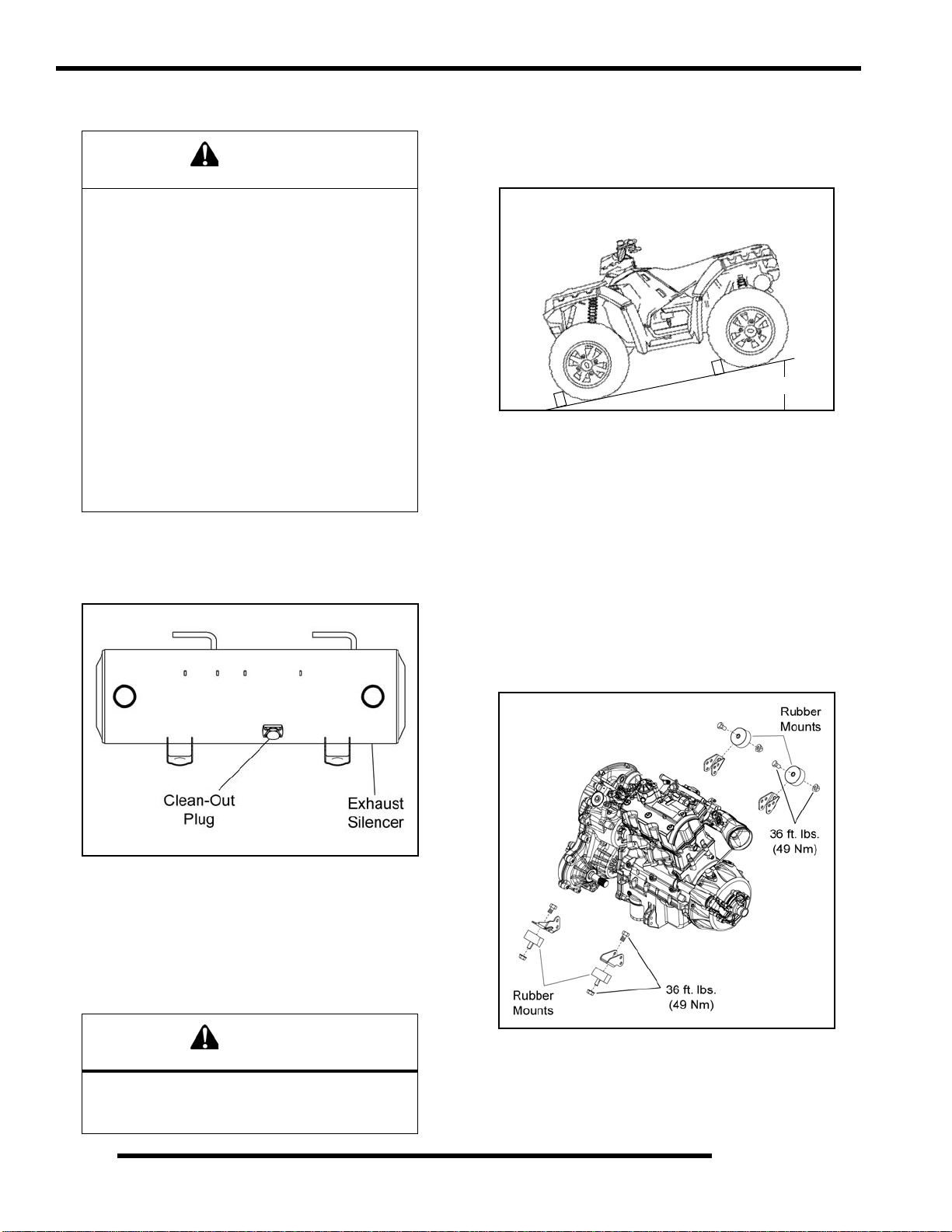
accumulated carbon as follows:
5. If particles are still suspected to be in the silencer, back the
machine onto an incline so the rear of the machine is 1 ft.
(30.5 cm) higher than the front. Place the transmission in
park and block the wheels. Repeat steps 3 and 4 (see
WARNING).
1 ft.
6. If particles are still suspected to be in the silencer, drive the
machine onto the incline so the front of the machine is 1 ft.
(30.5 cm) higher than the rear. Place the transmission in
park and block the wheels. Repeat Steps 3 and 4 (see
WARNING).
7. Stop the engine and allow the silencer to cool. Reinstall the
clean out plug.
1. Remove the clean out plug on the bottom of the silencer.
2. Place the transmission in park, and start the engine.
3. Purge accumulated carbon from the exhaust system by
momentarily revving the engine several times.
4. If some carbon is expelled, cover the exhaust outlets and
lightly tap on the silencer around the clean out plug with a
rubber mallet while revving the engine several more times.
Engine Mount Fastener Torque
Check engine mounting fasteners and ensure they are tight.
Also inspect the condition of the rubber mounts. If rubber
mounts are cracked or show signs of fatigue, replace them.
CAUTION
Wear protective gloves when covering the
exhaust outlets. Serious burns could result from
contact with exhaust components.
2.16
Page 28
MAINTENANCE
TRANSMISSION AND GEARCASES
Transmission Lubrication
NOTE: It is important to follow the transmission
maintenance intervals described in the Periodic
Maintenance Chart. Regular fluid level inspections
should be performed as well.
The transmission fluid leve l should be checked and changed in
accordance with the maintenance schedule.
• Be sure vehicle is positioned on a level surface when
checking or changing the fluid.
• Check vent hose to be sure it is routed properly and
unobstructed.
Transmission Fluid Level Check
The fill plug is located on the right-hand side of the
transmission. Access the fill plug through the rear right-hand
wheel well. Maintain the fluid level even with the bottom
threads of the fill plug hole.
1. Position vehicle on a level surface.
Transmission Fluid Change
Access the drain plug through the rear right-hand wheel well.
The plastic skid plate can be removed for better access to the
drain plug.
1. Remove the fill plug (refer to “Transmission Fl uid Level
Check”).
2. Place a drain pan under the transmission drain plug.
3. Remove the drain plug and allow fluid to drain complete ly.
2
2. Remove the fill plug and check the fluid level.
Fill Plug
10-14 ft. lbs.
(14-19 Nm)
Transmission fluid
flush with the bottom
of thread area.
3. If fluid level is not even with the b ottom threads, add the
recommended fluid as needed. Do not overfill.
4. Reinstall the fill plug and torque to specification.
Drain Plug
10-14 ft. lbs. (14-19 Nm)
4. Clean the drain plug magnetic surface.
5. Reinstall drain plug with a new O-ring and torque to
specification.
6. Add the recommended amount of fluid through the fill plug
hole. Maintain the fluid level at the bottom of the fill plug
hole when filling the transmission. Do not overfill.
Fill Plug
10-14 ft. lbs.
(14-19 Nm)
=
Recommended Transmission Lubricant:
Synthetic Sportsman XP Transmission Fluid
(PN 2877606) (Quart)
Capacity: 32 oz. (946 ml)
7. Reinstall fill plug with a new O-ring and torque to
specification.
= T
Drain/Fill Plug Torque:
10-14 ft. lbs. (14-19 Nm)
= T
Drain/Fill Plug Torque:
10-14 ft. lbs. (14-19 Nm)
8. Check for leaks. Dispose of used fluid properly.
2.17
Page 29

MAINTENANCE
Front Gearcase Lubrication
NOTE: It is important to follow the front gearcase
maintenance intervals described in the Periodic
Maintenance Chart. Regular fluid level inspections
should be performed as well.
The front gearcase fluid level should be checked and changed in
accordance with the maintenance schedule.
• Be sure vehicle is positioned on a level surface when
checking or changing the fluid.
• Check vent hose to be sure it is routed properly and
unobstructed.
Front Gearcase Fluid Level Check
The fill plug is located on the right side of the fron t gearcase.
Access the fill plug through the front right-hand wheel well or
through the front lower bumper. Maintain the fluid level even
with the bottom threads of the fill plug hole.
1. Position vehicle on a level surface.
2. Remove the fill plug and check the fluid level.
Fill Plug
8-10 ft. lbs.
(11-14 Nm)
Front Gearcase Fluid Change:
The drain plug is located on the bottom side of the front
gearcase. Access the drain plug through the access hole in the
front skid plate.
1. Remove the fill plug (refer to “Front Gearcase Fluid Level
Check”).
2. Place a drain pan under the front gearcase drain plug.
3. Remove the drain plug and allow fluid to drain completel y.
Drain Plug
8-10 ft. lbs.
(11-14 Nm)
4. Clean the drain plug magnetic surface.
Fill Plug
8-10 ft. lbs.
(11-14 Nm)
Gearcase fluid
flush with the bottom
of thread area.
3. If fluid level is not even with the b ottom threads, add the
recommended fluid as needed. Do not overfill.
4. Reinstall the fill plug and torque to specification.
= T
Drain / Fill Plug Torque:
8-10 ft. lbs. (11-14 Nm)
5. Reinstall drain plug with a new O-ring and torque to
specification.
6. Add the recommended amount of fluid through the fill hole.
Maintain the fluid level e ven with the bottom threads of the
fill plug hole.
=
Recommended Front Gearcase Fluid:
Premium LT Demand Drive Fluid
(PN 2876251) (Quart)
Capacity: 9.3 oz. (275 ml)
7. Reinstall fill plug with a new O-ring and torque to
specification.
= T
Drain / Fill Plug Torque:
8-10 ft. lbs. (11-14 Nm)
2.18
8. Check for leaks. Dispose of used fluid properly.
Page 30
MAINTENANCE
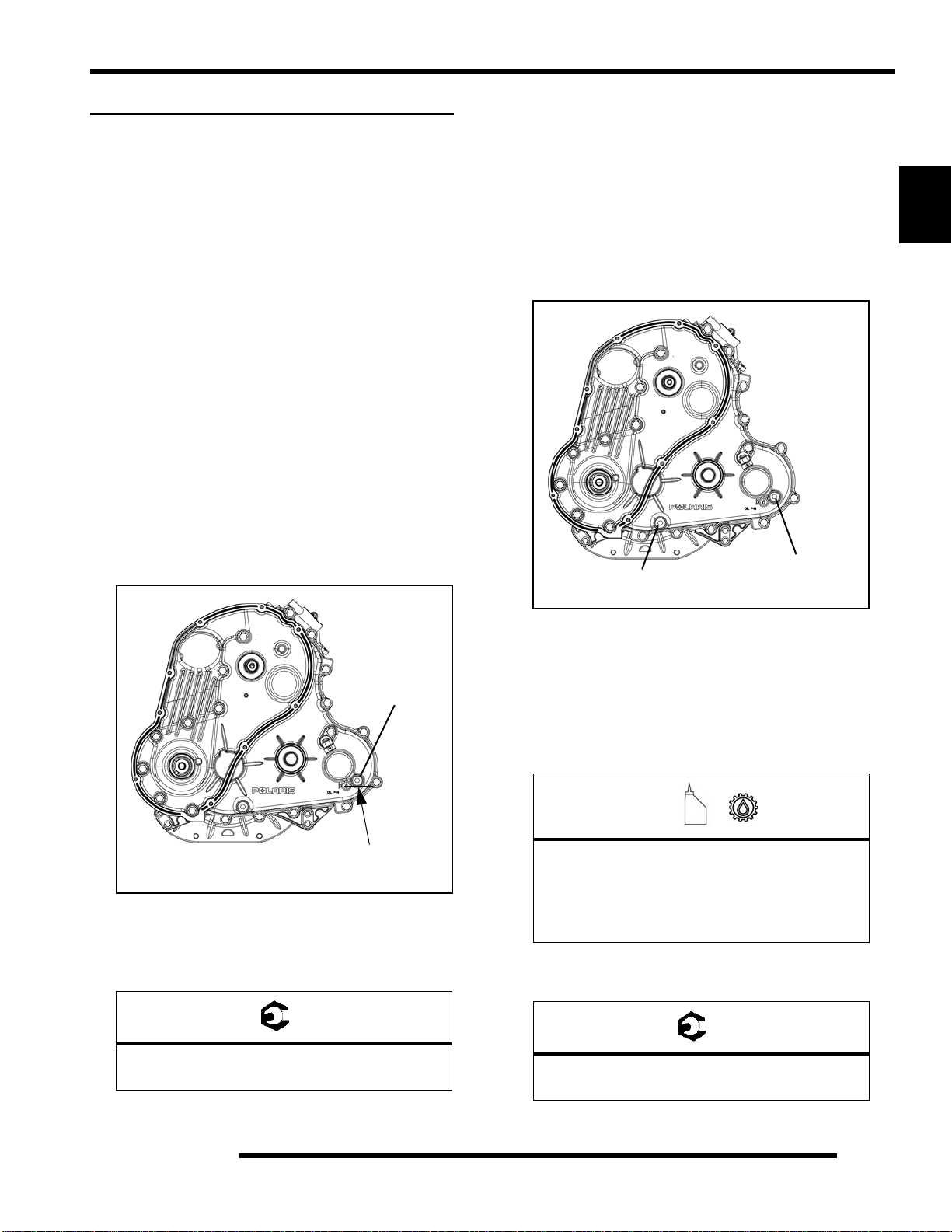
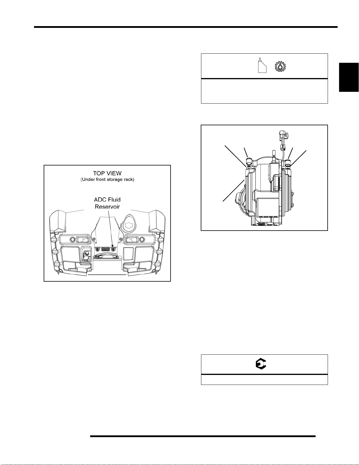
Front Gearcase ADC Fluid
NOTE: It is important to follow the front gearcase
maintenance intervals described in the Periodic
Maintenance Chart. Regular fluid level inspections
should be performed as well.
The front gearcase ADC fluid level should be checked and
changed in accordance with the maintenance schedule.
Front Gearcase ADC Fluid Level Check
The ADC fluid reservoir is located underneath the front rack as
shown below. Maintain the fluid level between the “MIN” and
“MAX” levels indicated on the reservoir.
1. Disengage the anchors and remove front rack assembly.
2. Check the fluid level of the ADC reservoir.
5. Begin the bleeding process by filling reservoir to the
“MAX” level with clean ADC Front Drive Fluid.
=
Recommended ADC Fluid:
Premium ADC Front Drive Fluid
(PN 2876144) (Quart)
6. Locate bleeder valves found on each side of the front
gearcase and remove the protective caps.
Bleeder
Valve
Front
Gearcase
CapCap
Bleeder
Valve
2
3. If fluid level is below the minimum mark on the reservoir,
remove the cap and add the recommended fluid.
4. Reinstall the cap and front rack assembly.
Front Gearcase ADC Fluid Change:
1. Position the vehicle on a level surface and allow the
vehicle to sit for at least 30 minutes.
2. Thoroughly clean the areas around the ADC reservoir and
bleeder valves.
3. Remove the reservoir cap and diaphragm assembly.
4. Make sure the fluid inside the reservoir is free of debris. If
any debris is found, use a clean shop towel or suction device
to remove it from the reservoir.
NOTE: Debris in the reservoir may result in
inadequate bleeding and reduced performance of
the system.
7. Attach a clean clear hose to one of the bleeder valves.
8. Slowly loosen the valve (counter-clockwise) and allow
fluid and trapped air to flow from the fitting.
IMPORTANT: Do not allow ADC fluid in reservoir to
drop below the “MIN” fill line. Close bleeder valve
before the fluid level drops below the “MIN” fill line.
Refilling an empty reservoir will result in air pockets
becoming trapped.
9. Close the valve when clean (bubble-free) fluid begins to
flow from the valve.
10. Repeat steps 7-9 on the remaining bleeder valve.
11. Torque the bleeder valves to specification and reinstall the
protective caps.
= T
Bleeder Valve Torque: 80 in. lbs. (9 Nm)
12. Fill reservoir to a level midway between “MAX” and
“MIN” fill lines. Verify no debris is found in reservoir
fluid.
13. Install the reservoir cap and diaphragm securely and wipe
clean any fluid residue.
2.19
Page 31

MAINTENANCE
Rear Gearcase Lubrication
NOTE: It is important to follow the rear gearcase
maintenance intervals described in the Periodic
Maintenance Chart. Regular fluid level inspections
should be performed as well.
The rear gearcase fluid level should be checked and changed in
accordance with the maintenance schedule.
• Be sure vehicle is positioned on a level surface when
checking or changing the fluid.
• Check vent hose to be sure it is routed properly and
unobstructed.
Rear Gearcase Fluid Level Check:
The fill plug is located on the right side of the rear gearcase.
Maintain the fluid level even with the bottom threads of the fill
plug hole.
1. Position the vehicle on a level surface.
2. Remove the fill plug and check the fluid level.
Rear Gearcase Fluid Change:
The drain plug is located on the bottom right-hand si de of the
rear gearcase. Access the drain plug from the rear right-hand
side of the ATV.
1. Remove the fill plug (refer to “Rear Gearcase Fluid Level
Check”).
2. Place a drain pan under the rear gearcase drain plug.
3. Remove the drain plug and allow the fluid to drain
completely.
Fill Plug
10-14 ft. lbs.
(14-19 Nm)
Fill Plug
10-14 ft. lbs.
(14-19 Nm)
Gearcase fluid
flush with the bottom
of thread area.
3. If fluid level is not even with the b ottom threads, add the
recommended fluid as needed. Do not overfill.
4. Reinstall fill plug and torque to specification.
= T
Drain / Fill Plug Torque:
10-14 ft. lbs. (14-19 Nm)
Gearcase fluid
flush with the bottom
of thread area.
4. Clean the drain plug magnetic surface.
5. Reinstall drain plug with a new O-ring and torque to
specification.
6. Add the recommended amount of fluid through the fill hole.
Maintain the fluid level e ven with the bottom threads of the
fill plug hole.
Drain Plug
10-14 ft. lbs.
(14-19 Nm)
=
Recommended Rear Gearcase Lubricant:
ATV Angle Drive Fluid (PN 2871653)
Capacity: 7.1 oz. (210 ml)
7. Reinstall fill plug with a new O-ring and torque to
specification.
= T
2.20
Drain / Fill Plug Torque:
10-14 ft. lbs. (14-19 Nm)
8. Check for leaks. Dispose of used fluid properly.
Page 32

MAINTENANCE
COOLING SYSTEM
Cooling System Overview
The engine coolant level is controlled, or maintained, by the
recovery system. The recovery system components are the
recovery bottle, radiator filler neck, radiator pressure cap and
connecting hose.
As coolant operating temperature increases, the expanding
(heated) excess coolant is forced out of the radiator past the
pressure cap and into the recovery bottle. As engine coolant
temperature decreases the contracting (cooled) coolant is drawn
back up from the bottle, past the pressure cap, and into the
radiator.
NOTE: Some coolant level drop on new vehicles is
normal as the system is purging itself of trapped air.
Observe coolant level often during the break-in
period.
CAUTION
Overheating of engine could occur if air is not
fully purged from system.
Polaris recommends the use of Polaris Premium 60/40 antifreeze/coolant or a 50/50 mixture of high quality aluminum
compatible anti-freeze/coolant and distilled water.
NOTE: Polaris Premium 60/40 is already premixed
and ready to use. Do not dilute with water.
With the engine at operating temperature, the coolant level
should be between the MAX and MIN marks on the coolant
recovery bottle. If not, perform the following procedure.
1. Position the vehicle on a level surface.
2. View the coolant level in the recovery bottle. The coolant
level can be viewed from inside the front right wheel well.
3. If the coolant level is below the “MIN” line on the bottle,
remove the front rack assembly to access the radiator
pressure cap and recovery bottle cap.
NOTE: If overheating is evident, allow system to
cool completely and check coolant level in the
radiator and inspect for signs of trapped air in
system.
2
Coolant Level Inspection
The pressure cap and recovery bottle are located underneath the
front rack as shown below. Maintain the coolant level between
the “MIN” and “MAX” levels indicated on the recovery bottle.
WARNING
Never remove the pressure cap when the
engine is warm or hot. Escaping steam can
cause severe burns. The engine must be cool
before removing the pressure cap.
4. Remove the pressure cap. Using a funnel, add coolant to
the top of the radiator filler neck.
5. Reinstall the pressure cap.
NOTE: Use of a non-standard pressure cap will not
allow the recovery system to function properly.
6. Remove recovery bottle cap and add coolant using a funnel.
7. Fill recovery bottle to “MAX” level with Polaris Premium
60/40 Anti-Freeze/Coolant or a 50/50 mixture of antifreeze/coolant and distilled water as required for freeze
protection in your area.
8. Reinstall the recovery bottle cap.
2.21
Page 33

MAINTENANCE
9. If coolant was required, start engine and check for leaks.
Make sure radiator fins are clean to prevent overheating.
10. Add coolant as needed. Maintain the coolant level between
the “MIN” and “MAX” marks on the bottle.
11. Reinstall the front rack assembly.
Cooling System Hoses
1. Inspect all hoses for cracks, deterioration, abrasion or
leaks. Replace if necessary.
Coolant Strength / Type
Test the strength of the coolant using an antifreeze hydrometer .
Antifreeze Hydrometer
• A 50/50 or 60/40 mixture of antifreeze and distilled
water will provide the optimum cooling, corrosion
protection, and antifreeze protection.
• Do not use tap water, straight antifreeze, or straight
water in the system. Tap water contains minerals and
impurities which build up in the system.
• Straight water or antifreeze may cause the system to
freeze, corrode, or overheat.
=
Recommended Anti-Freeze/Coolant:
Polaris 60/40 Anti-Freeze/Coolant
(PN 2871534) (Quart)
2. Check tightness of all hose clamps.
CAUTION
Do not over-tighten hose clamps at radiator, or
radiator fitting may distort, causing a restriction
to coolant flow. Radiator hose clamp torque is
36 in. lbs. (4 Nm).
NOTE: For further information on the engine cooling
system, refer to Chapter 4.
2.22
Page 34

MAINTENANCE
PVT / FINAL DRIVE / WHEEL AND TIRE
PVT Drying
NOTE: If operating the ATV through water, be sure
to check the PVT system components for water
ingestion. After operating in water, the ATV should
be checked immediately.
1. Access the PVT drain plug on the bottom of the PVT cover
using a long flat blade screwdriver between the frame and
left-hand lower control arm from the rear of the ATV.
2. Remove the PVT drain plug and O-ring.
Drive Belt Removal
Refer to Chapter 7 “Clutching (PVT)” for more detail.
1. Elevate vehicle and remove the left rear wheel.
2. Remove the lower left-hand frame suppo rt.
3. Remove the (11) screws retaining the outer PVT co ver.
Pull the PVT cover out the LH wheel well.
4. Insert the belt removal tool PN 2877408 into the driven
clutch (tool included with vehicle’s tool kit).
NOTE: Make sure the tool is square with the
moveable sheave surface of the driven clutch.
5. Rotate the tool to open the driven clutch.
6. Walk the belt out of the driven clutch and drive clutch, and
remove the belt from the vehicle.
Drive Shaft Boot Inspection
Inspect the front and rear drive shaft boots for damage, tears,
wear, or leaking grease. If the rubber boots exhibit any of these
symptoms, replace the boot(s). Refer to Chapter 8 for drive
shaft boot replacement.
2
3. Allow the water to drain out completely.
4. Reinstall the drain plug and O-ring.
5. Start the engine and shift into park.
6. Apply varying throttle for 10-15 seconds to expel the
moisture and air-dry the belt and clutches.
NOTE: Do not hold the throttle wide open for more
than 10 seconds.
Rear
NOTE: Remove the CV boot shield from the front
lower A-arms to inspect the front outer CV boots.
Front
7. Allow the engine RPM to return to idle, then shift into low
gear.
8. Test the PVT system for belt slippage. If the belt slips,
repeat the process.
2.23
Page 35
MAINTENANCE
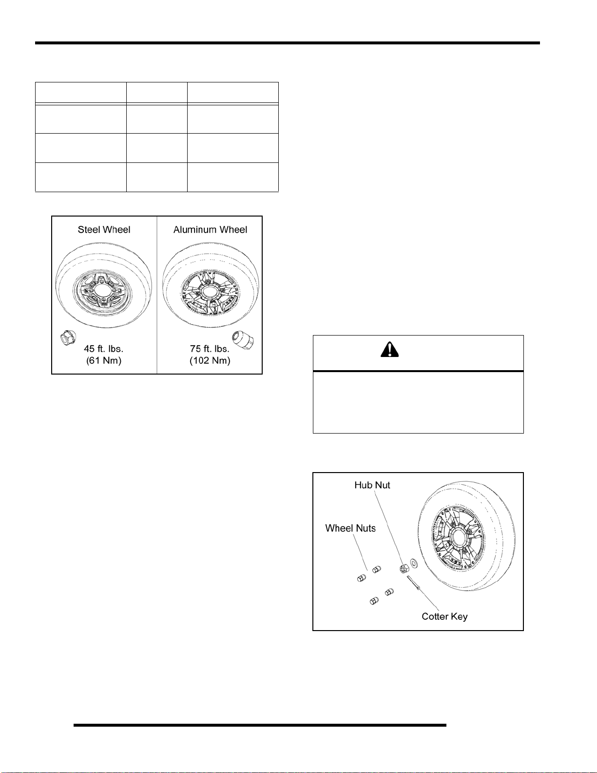
Wheel and Hub Torque Table
Item Nut Type Specification
Aluminum Wheels
Steel Wheels
Hub Retaining Nuts
(Front & Rear)
Tapered Nut
(Long)
Tapered Nut
(Short)
- 80 ft. lbs. (108 Nm)
75 ft. lbs. (102 Nm)
45 ft. lbs. (61 Nm)
Wheel Installation
1. Verify the transmission is still in PARK and the parking
brake is locked.
2. Install the wheel hub, washers, and hub nut, if previously
removed.
3. Place the wheel in the correct position on the wh eel hub.
Be sure the valve stem is toward the outside and rotatio n
arrows on the tire point toward forward rotation.
4. Install the wheel nuts and finger tighten them to align the
center of the wheel holes with the center of the tapered nuts.
IMPORTANT: It is possible to torque the wheel nut on
a steel rim without the nut being centered in the hole.
Be sure to center the wheel nuts before applying
torque to prevent wheel nuts from coming loose.
5. Carefully lower the vehicle to the ground.
6. Torque the wheel nuts and/or hub nut to the proper torque
specification listed in the “Wheel and Hub Torque Table”.
Wheel Removal
1. Position the vehicle on a level surface.
2. Stop the engine, place the transmission in PARK and lock
the parking brake.
3. Loosen the wheel nuts slightly. If wheel hub remov al is
required, remove the cotter key and loosen the hub nut
slightly.
4. Elevate the appropriate side of the vehicle by placing a
suitable stand under the footrest frame.
5. Remove the wheel nuts and remove the wheel.
6. If hub removal is required, remove the hub nut and washers.
CAUTION
Improperly installed wheels could affect vehicle
handling and tire wear. On vehicles with tapered
rear wheel nuts, make sure tapered end of nut
goes into taper on wheel. Be sure to properly
torque and install all wheel nuts.
7. If the hub nut was removed, install a new cotter pin after
the hub nut has been tightened.
2.24
Page 36

MAINTENANCE
Tire Pressure
Tire Pressure Inspection (PSI - Cold)
Front Rear
7 psi (48 kPa) 5 psi (34.5 kPa)
Tire Inspection
WARNING
Operating an ATV with worn tires will increase
the possibility of the vehicle skidding and
possible loss of control.
Worn tires can cause an accident.
Always replace tires when the tread depth
measures 1/8” (.3 cm) or less.
CAUTION
Maintain proper tire pressure.
Refer to the warning tire pressure decal
applied to the vehicle.
Improper tire inflation may affect
ATV maneuverability.
When replacing a tire always use original
equipment size and type.
The use of non-standard size or type tires may
affect ATV handling.
Tire Tread Depth
Always replace tires when tread depth is worn to 1/8” (3 mm) or
less.
Tread
Depth 1/8” (3 mm)
ELECTRICAL AND IGNITION SYSTEM
Battery Maintenance
Keep battery terminals and connections free of corrosion. If
cleaning is necessary, remove the corrosion with a stiff wire
brush. W ash with a solution of one tablespoon baking soda and
one cup water. Rinse well with tap water and dry of f with clean
shop towels. Coat the terminals with dielectric grease or
petroleum jelly.
WARNING
Battery electrolyte is poisonous. It contains sulfuric
acid. Serious burns can result from contact with
skin, eyes or clothing. Antidote:
External: Flush with water.
Internal: Drink large quantities of water or milk.
Follow with milk of magnesia, beaten egg, or
vegetable oil. Call physician immediately.
Eyes: Flush with water for 15 minutes and get
prompt medical attention.
Batteries produce explosive gases. Keep sparks,
flame, cigarettes, etc. away. Ventilate when
charging or using in an enclosed space. Always
shield eyes when working near batteries. KEEP
OUT OF REACH OF CHILDREN.
NOTE: Absorbed Glass Mat (AGM) batteries are
permanently sealed at the time of manufacture.
AGM batteries are designed to minimize gassing and
water loss, but can vent if overcharged.
IMPORTANT: Never attempt to open the battery. If the
seal is broken, the battery will be ruined and will fail
within a few weeks.
2
NOTE: If battery voltage is below 12.6V, fully charge
the battery before putting into service. Charge for 35 hours at a voltage not to exceed 14.6V or 10 Amps.
Voltage should reach at least 14.4V before end of
charge.
2.25
Page 37

MAINTENANCE
Battery Removal
1. Remove the seat to access the battery.
Retaining Screw
2. Disconnect battery negative (-) (black) cable first, followed
by the positive (+) (red) cables.
CAUTION
To reduce the chance of sparks: Whenever
removing the battery, disconnect the negative
(black) cable first.
3. Remove the screw retaining the hold-down strap n ear the
bottom front portion of the battery and remove the strap.
4. Lift the battery out of the ATV.
Battery Installation
IMPORTANT: Using a new battery that is not fully
charged can damage the battery, resulting in a short
battery life and can hinder performance. Follow the
battery charging procedure before installation.
5. Place the spacers on top of the battery terminals. Be sure
they are placed between the battery terminal and cable(s).
Positive
Cables
SpacerSpacer
6. Connect and tighten the positive (+) (red) battery cable first,
followed by the negative (-) (black) battery cable.
Negative
Cable
CAUTION
To reduce the chance of sparks: Whenever
installing the battery, install the
negative (black) cable last.
7. Verify cables are properly routed and fasteners are tight.
NOTE: The cables should be safely tucked away at
the front of the battery.
8. Reinstall the seat.
Spark Plug Service
1. Remove the seat and upper right-hand side panel.
2. Disconnect the shift linkage from the shift lever.
3. Remove the spark plug caps. Clean plug area so no dirt and
debris can fall into engine when plugs are removed.
1. Ensure the battery is fully charged (see Chapter 12).
2. Place the battery into the ATV on its side with the positive
(+) terminal towards the right side of the ATV.
3. Install the hold-down strap and the retaining screw .
4. Coat the battery terminals and bolt threads with Dielectric
Grease (PN 2871329) or petroleum jelly.
2.26
4. Using a 14 mm deep-well socket with an extension, remove
the spark plug.
Page 38

MAINTENANCE
Spark Plug Inspection / Installation
1. Inspect electrodes for wear and carbon buildup. Look for
a sharp outer edge with no rounding or erosion of the
electrodes.
2. Clean with electrical contact cleaner or a glass bead spark
plug cleaner only. CAUTION: A wire brush or coated
abrasive should not be used.
3. Measure gap with a wire gauge. Refer to specifications in
the following illustration for proper spark plug type and
gap. Adjust gap if necessary by carefully bending the side
electrode.
Spark Plug Gap
Gap - .035" (0.90 mm)
4. If necessary, replace spark plug with proper type.
CAUTION: Severe engine damage may occur if the
incorrect spark plug is used.
Engine / Chassis Ground
Periodically inspect the electrical ground cable attachments.
Cables and connections should be tight and corrosion-free.
Inspect the battery-to-chassis connection underneath the seat.
This connection allows the chassis to provide a ground path.
Inspect the chassis-to-engine connection on the left side of the
engine attached to the engine/transmission housing. This
connection allows the engine to provide a ground path.
2
Recommended Spark Plug
Champion REA6MC or REA8MCL
Spark Plug Torque:
18 ± 1.5 ft. lbs. (25 ± 2 Nm)
5. Apply a small amount of anti-seize compound to the spark
plug threads.
6. Install spark plugs and torque to specification.
7. Make sure the high tension leads are retained by the airbox.
8. Reinstall the shift linkage, upper right-hand side panel, and
seat.
2.27
Page 39

MAINTENANCE
STEERING
Steering Inspection
The steering components should be checked periodically for
loose fasteners, worn tie rod ends, and damage. Also check to
make sure all cotter pins are in place. If cotter pins are removed,
they must not be re-used. Always use new cotter pins.
Bolt
Carriage
Bolt
Bracket
Nut
Cotter
Pin
Screw
Bushings
Steering
Post
Nut
Upper Post
PS Unit
Steering
Bracket
Bolt
Drive
Brackets
Power Steering Unit (EPS Models)
The power steering unit can be accessed through the front left
wheel well by removing the mud guard.
PS Unit
Frequently clean the areas around and on top of the power
steering unit to allow for proper cooling.
Bolts
Lower
Post
Washer
Nut
Cotter
Pin
Bolts
Jam Nut
Rod End
Tie Rod
Jam Nut
Rod End
Replace any worn or damaged steering components. Steering
should move freely through entire range of travel without
binding. Check routing of all cables, hoses, and wiring to be sure
the steering mechanism is not restricted or limited.
NOTE: Whenever steering components are
replaced, check front end alignment. Use only
genuine Polaris parts.
WARNING
Due to the critical nature of the procedures
outlined in this chapter, Polaris recommends
steering component repair and adjustment be
performed by an authorized Polaris Dealer. Only
a qualified technician should replace worn or
damaged steering parts. Use only genuine
Polaris replacement parts.
IMPORTANT: Be sure to clean these areas thoroug hly
after riding through muddy conditions.
2.28
Page 40

MAINTENANCE
Tie Rod End / Steering Inspection
To check for play in the tie rod end, grasp the steering tie rod,
pull in all directions feeling for movement.
• Repeat inspection for inner tie rod end (on steering
post).
• Replace any worn steering components. Steering should
move freely through entire range of travel without
binding.
3. Tie a length of string between two stands as shown in the
following illustration. Position the stands so the st ring is
flush or parallel with the side of the rear tire.
2
Stand
String
2
1
• Elevate front end of machine so front wheels are off the
ground. Check for any looseness in front hub / wheel
assembly by grasping the tire firmly at top and bottom
first, and then at front and rear. Try to move the wheel
and hub by pushing inward and pulling outward.
• If abnormal movement is detected, inspect the hub and
wheel assembly to determine the cause.
Toe Alignment
Use the following procedure to check the toe alignment of the
vehicle. The recommended toe alignment is 1/8”-1/4” (3-6 mm)
toe out.
1. Position the vehicle on a smooth level surface.
2. Set handlebars in a straight ahead position and secure
handlebars in this position.
NOTE: The steering post frog can be used as an
indicator of whether the handlebars are straight. The
frog should always point straight back from the
steering post.
NOTE: If available, you may use a long straight-edge
instead of a string.
4. Measure the distance from the string to the rim at the front
(1) and rear (2) of the front rim. The rear measurement
should be 1/16”-1/8” (2-3 mm) more than the front
measurement on each side of the vehicle to obtain the
recommended 1/8”-1/4” (3-6 mm) toe out alignment.
5. Repeat the measurement procedure on the other side of the
vehicle.
NOTE: If you discover improper alignment, refer to
“Toe Alignment Adjustment” procedure.
= In. / mm.
Wheel Toe-out Alignment:
1/8 - 1/4” (3 - 6 mm)
2.29
Page 41

MAINTENANCE
Toe Alignment Adjustment
If toe alignment is incorrect, measure the distance between
vehicle center and each wheel. This will tell you which tie rod
needs adjusting.
NOTE: Be sure handlebars are straight ahead before
determining which tie rod(s) need adjustment.
CAUTION
During tie rod adjustment, it is very important that
the following precautions be taken when
tightening tie rod end jam nuts.
If the rod end is positioned incorrectly it will not
pivot, and may break
To adjust toe alignment:
• Hold tie rod end to keep it from rotating.
• Loosen jam nuts at both ends of the tie rod.
• Shorten or lengthen the tie rod until alignment is as
required to achieve the proper toe out setting.
• Important: When tightening the tie rod end jam nuts,
the rod ends must be held parallel to prevent rod end
damage and premature wear. Damage may not be
immediately apparent if done incorrectly. See
illustration.
SUSPENSION
Suspension Inspection
Compress and release the suspension. Damping should be
smooth throughout the range of travel.
• Check all suspension components and mounting
fasteners for wear or damage.
• Inspect each shock body for leakage.
Suspension Spring Pre-Load Adjustment
The front and rear shock absorber springs are adjustable. Rotate
the adjuster cam either direction to increase or decrease spring
tension. Always adjust both sides equally.
Operator weight and vehicle loading affect suspension spring
pre-load requirements. Use Spanner Wrench (PN 2870872) to
adjust pre-load as necessary to avoid bottoming of the shocks.
Shock Spanner Wrench
(PN 2870872)
2.30
Page 42

MAINTENANCE
BRAKE SYSTEM
Brake Fluid Inspection
The following checks are recommended to keep the brake
system in good operating condition. Service life of brake system
components depends on operating conditions. Inspect brakes in
accordance with the maintenance schedule and before each ride.
• Keep fluid level in the hand master cylinder reservoir to
the indicated level inside reservoir.
Fluid Level “Eye”
• Check the fluid level “eye”. If it is clear, it is an
indication that fluid is needed or the brake pads may be
worn, which can reduce the fluid level.
Full
Low
• Check the fluid level of the auxiliary brake master
cylinder reservoir. Add fluid to the indicated level.
2
Figure 2-31
• Use Polaris DOT 4 Brake Fluid (PN 2872189).
CAUTION
DO NOT OVERFILL!
Excess brake fluid may cause brake drag.
Fill to the indicated fill line or specification.
• Check brake system for fluid leaks, excessive travel or
spongy feel.
• If required, add brake fluid to .25” - .30” (6 - 8 mm)
from the top of the reservoir.
.25” - .30” (6 - 8 mm)
From the Top of Reservoir
• Check brake pads for wear, damage or looseness.
• Check surface condition of the disc.
• Inspect thickness of brake pad friction material.
Brake Pad Inspection
Inspect brake pad friction material for excessive wear.
Brake Pad Inspection
Brake Pad
Measure
Service Limit - .040” (1 mm)
Thickness
Hose / Fitting Inspection
Check brake system hoses and fittings for cracks, deterioration,
abrasion, and leaks.Tighten any loose fittings and replace any
worn or damaged parts.
2.31
Page 43

MAINTENANCE
Auxiliary Brake Pedal
The hydraulic auxiliary brake system requires no adjustment.
Frequently check the brake fluid level for the auxiliary brake
system by viewing the level in the master cylinder reservoir
located underneath the front rack assembly (see Figure 2-31).
Foot Brake
• Check the effectiveness of the auxiliary brake by
applying approximately 50 lbs. (23 kg) of downward
force on the pedal.
• If brake pedal requires an excessive amount of travel to
operate, inspect brake pads, pedal, linkage springs, rear
master cylinder and hoses for wear, damage or leaka ge.
Replace components as needed.
2.32
Page 44

MAINTENANCE
MAINTENANCE LOG
Service Date Hours / Miles (km) Service Performed / Comments Dealer / Technician
20 Hours / 1 Month
(Break-In)
100 / 6 Months
2
2.33
Page 45

MAINTENANCE
NOTES
2.34
Page 46

ELECTRONIC FUEL INJECTION
CHAPTER 3
ELECTRONIC FUEL INJECTION
SPECIAL TOOLS . . . . . . . . . . . . . . . . . . . . . . . . . . . . . . . . . . . . . . . . . . . . . . . . . . . . . . . 3.2
FUEL TANK. . . . . . . . . . . . . . . . . . . . . . . . . . . . . . . . . . . . . . . . . . . . . . . . . . . . . . . . . . . . 3.4
FUEL LINE. . . . . . . . . . . . . . . . . . . . . . . . . . . . . . . . . . . . . . . . . . . . . . . . . . . . . . . . . . . . . 3.5
EFI SERVICE NOTES. . . . . . . . . . . . . . . . . . . . . . . . . . . . . . . . . . . . . . . . . . . . . . . . . . . . 3.5
EFI SYSTEM LAYOUT . . . . . . . . . . . . . . . . . . . . . . . . . . . . . . . . . . . . . . . . . . . . . . . . . . . 3.6
EFI COMPONENTS. . . . . . . . . . . . . . . . . . . . . . . . . . . . . . . . . . . . . . . . . . . . . . . . . . . . . . 3.7
ELECTRONIC FUEL INJECTION . . . . . . . . . . . . . . . . . . . . . . . . . . . . . . . . . . . . . . . . . . . 3.9
ELECTRONIC CONTROL UNIT (ECU). . . . . . . . . . . . . . . . . . . . . . . . . . . . . . . . . . . . . . 3.10
ECU SERVICE . . . . . . . . . . . . . . . . . . . . . . . . . . . . . . . . . . . . . . . . . . . . . . . . . . . . . . . .3.10
ECU REMOVAL / REPLACEMENT . . . . . . . . . . . . . . . . . . . . . . . . . . . . . . . . . . . . . . . .3.11
FUEL PUMP . . . . . . . . . . . . . . . . . . . . . . . . . . . . . . . . . . . . . . . . . . . . . . . . . . . . . . . . . . 3.11
FUEL SENDER / PUMP TEST. . . . . . . . . . . . . . . . . . . . . . . . . . . . . . . . . . . . . . . . . . . .3.12
FUEL PUMP / FUEL TANK REMOVAL . . . . . . . . . . . . . . . . . . . . . . . . . . . . . . . . . . . . .3.13
FUEL PUMP / FUEL TANK INSTALLATION . . . . . . . . . . . . . . . . . . . . . . . . . . . . . . . . .3.14
FUEL PRESSURE REGULATOR . . . . . . . . . . . . . . . . . . . . . . . . . . . . . . . . . . . . . . . . . . 3.14
FUEL INJECTORS . . . . . . . . . . . . . . . . . . . . . . . . . . . . . . . . . . . . . . . . . . . . . . . . . . . . . 3.14
FUEL INJECTOR SERVICE. . . . . . . . . . . . . . . . . . . . . . . . . . . . . . . . . . . . . . . . . . . . . .3.14
FUEL INJECTOR TEST / REPLACEMENT . . . . . . . . . . . . . . . . . . . . . . . . . . . . . . . . . .3.15
CRANKSHAFT POSITION SENSOR (CPS) . . . . . . . . . . . . . . . . . . . . . . . . . . . . . . . . . . 3.16
CPS TEST / REPLACEMENT . . . . . . . . . . . . . . . . . . . . . . . . . . . . . . . . . . . . . . . . . . . .3.16
TEMP / MANIFOLD ABSOLUTE PRESSURE SENSOR (T-MAP) . . . . . . . . . . . . . . . . . 3.17
T-MAP TEST / REPLACEMENT. . . . . . . . . . . . . . . . . . . . . . . . . . . . . . . . . . . . . . . . . . .3.17
IDLE AIR CONTROL VALVE (IAC) . . . . . . . . . . . . . . . . . . . . . . . . . . . . . . . . . . . . . . . . . 3.17
IAC TEST . . . . . . . . . . . . . . . . . . . . . . . . . . . . . . . . . . . . . . . . . . . . . . . . . . . . . . . . . . . .3.17
IAC REPLACEMENT . . . . . . . . . . . . . . . . . . . . . . . . . . . . . . . . . . . . . . . . . . . . . . . . . . .3.18
THROTTLE POSITION SENSOR (TPS). . . . . . . . . . . . . . . . . . . . . . . . . . . . . . . . . . . . . 3.19
TPS RESISTANCE TESTS / TPS TESTER KIT. . . . . . . . . . . . . . . . . . . . . . . . . . . . . . .3.19
CHECKING TPS READING . . . . . . . . . . . . . . . . . . . . . . . . . . . . . . . . . . . . . . . . . . . . . .3.20
TPS ADJUSTMENT . . . . . . . . . . . . . . . . . . . . . . . . . . . . . . . . . . . . . . . . . . . . . . . . . . . .3.21
TPS REPLACEMENT. . . . . . . . . . . . . . . . . . . . . . . . . . . . . . . . . . . . . . . . . . . . . . . . . . .3.22
ENGINE COOLANT TEMPERATURE SENSOR (ECT) . . . . . . . . . . . . . . . . . . . . . . . . . 3.22
ECT SENSOR TEST . . . . . . . . . . . . . . . . . . . . . . . . . . . . . . . . . . . . . . . . . . . . . . . . . . .3.22
ECT SENSOR REPLACEMENT. . . . . . . . . . . . . . . . . . . . . . . . . . . . . . . . . . . . . . . . . . .3.23
IGNITION COIL . . . . . . . . . . . . . . . . . . . . . . . . . . . . . . . . . . . . . . . . . . . . . . . . . . . . . . . . 3.23
IGNITION COIL TESTS . . . . . . . . . . . . . . . . . . . . . . . . . . . . . . . . . . . . . . . . . . . . . . . . .3.23
IGNITION COIL AND HT LEAD REPLACEMENT . . . . . . . . . . . . . . . . . . . . . . . . . . . . .3.24
EFI DIAGNOSTICS . . . . . . . . . . . . . . . . . . . . . . . . . . . . . . . . . . . . . . . . . . . . . . . . . . . . . 3.25
INSTRUMENT CLUSTER TROUBLE CODE DISPLAY. . . . . . . . . . . . . . . . . . . . . . . . .3.25
FUEL SYSTEM TROUBLESHOOTING. . . . . . . . . . . . . . . . . . . . . . . . . . . . . . . . . . . . . . 3.28
EFI SYSTEM BREAK-OUT DIAGRAMS . . . . . . . . . . . . . . . . . . . . . . . . . . . . . . . . . . . . . 3.29
FUEL INJECTOR CIRCUITS . . . . . . . . . . . . . . . . . . . . . . . . . . . . . . . . . . . . . . . . . . . . .3.30
IDLE AIR CONTROL (IAC) CIRCUIT. . . . . . . . . . . . . . . . . . . . . . . . . . . . . . . . . . . . . . .3.31
CRANKSHAFT POSITION SENSOR (CPS) CIRCUIT. . . . . . . . . . . . . . . . . . . . . . . . . .3.31
FUEL PUMP / FUEL LEVEL SENSOR CIRCUIT. . . . . . . . . . . . . . . . . . . . . . . . . . . . . .3.32
FUEL PUMP CIRCUIT . . . . . . . . . . . . . . . . . . . . . . . . . . . . . . . . . . . . . . . . . . . . . . . . . .3.33
FUEL GAUGE CIRCUIT. . . . . . . . . . . . . . . . . . . . . . . . . . . . . . . . . . . . . . . . . . . . . . . . .3.33
ENGINE COOLANT TEMPERATURE SENSOR (ECT) CIRCUIT. . . . . . . . . . . . . . . . .3.34
THROTTLE POSITION SENSOR (TPS) CIRCUIT. . . . . . . . . . . . . . . . . . . . . . . . . . . . .3.34
TEMP / MANIFOLD ABSOLUTE PRESSURE SENSOR (T-MAP) CIRCUIT. . . . . . . . .3.35
DIAGNOSTIC CONNECTOR CIRCUIT . . . . . . . . . . . . . . . . . . . . . . . . . . . . . . . . . . . . .3.35
DIAGNOSTIC CONNECTOR CIRCUIT (EPS MODELS). . . . . . . . . . . . . . . . . . . . . . . .3.36
3
3.1
Page 47

ELECTRONIC FUEL INJECTION
SPECIAL TOOLS
Part Numbers / Descriptions
PART
NUMBER
PU-43506-A Fuel Pressure Gauge Kit
PS-48762 Fuel Pressure Gauge Adaptor
2201519 Throttle Position Sensor Tester Kit
Digital Wrench™ Diagnostic Software
PU-47063
PU-47471
IMPORTANT: For the most recent information on
Digital Wrench™ software and fileset downloads
please visit the website: www.polaris.diagsys.com
(Includes most recent version of software
and a serial number)
Digital Wrench™ SmartLink Module Kit
(PU-47470, PU-47469, PU-47468)
PU-47470
PU-47469
PU-47468
TOOL DESCRIPTION
Digital Wrench™
PC Interface Cable
Digital Wrench™
Vehicle Interface Cable
Digital Wrench™
SmartLink Module
Fuel Pressure Gauge Kit - PU-43506-A
IMPORTANT: The EFI fuel system remains under high
pressure, even when the engine is not running.
Before attempting to service any part of the fuel
system, the pressure must be relieved. The Fuel
Pressure Gauge Kit has an integrated pressure relief
valve that can be used to bleed off pressure.
Relief Valve
Adaptor shown is
included with kit.
Fuel Pressure Gauge Adaptor - PS-48762
Used in conjunction with PU-43506-A to check fuel pressure.
WARNING
* Gasoline is extremely flammable and explosive
under certain conditions.
* EFI components are under high pressure. Verify
system pressure has been relieved before
disassembly.
* Never drain the fuel system when the engin e is hot.
Severe burns may result .
* Do not overfill the tank. The tank is at full capacity
when the fuel reaches the bottom of the filler neck.
Leave room for expansion of fuel.
* Never start the engine or let it run in an enclosed
area. Gasoline powered engine exhaust fumes ar e
poisonous and can cause loss of consciousness and
death in a short time.
* Do not smoke or allow open flames or sparks in or
near the area where refueling is performed o r where
gasoline is stored.
* If you get gasoline in your eyes or if you should
swallow gasoline, seek medical attention immediately.
* If you spill gasoline on your skin or clothing,
immediately wash with soap and water and change
clothi n g .
* Always stop the engine and refuel outdoors or in a
well ventilated area.
7/16-20 Schrader
Throttle Position Sensor Tester Kit - 2201519
This tester allows the use of a digital multi-meter to test TPS
function and perform the “TPS Adjustment” procedure. Polaris
Dealers can order special tools from SPX Corporation.
3.2
Page 48

ELECTRONIC FUEL INJECTION
Digital Wrench™ Diagnostic Software
PU-47063
This dealer-only software installs on laptop computers equipped
with a CD drive and serial port connection, and is designed to
replace multiple shop tools often used to test EFI components.
It also includes step-by-step diagnostic procedures to aid
technician repair and troubleshooting.
Digital Wrench™
SmartLink Module Kit - PU-47471
This module kit contains the necessary cables and hardware to
communicate between the vehicle ECU and the Digital
Wrench™ diagnostic software. Polaris dealers can also order
the following separately: SmartLink Module PU-47468,
Vehicle Interface Cable PU-47469 and PC Interface Cable PU-
47470. This kit is available to Polaris dealers through our tool
supplier, SPX (1-800-328-6657).
PU-47469
Digital Wrench™ - Download Website
Located at: www.polaris.diagsys.com
3
PU-47468
PU-47470
Digital Wrench™ - Diagnostic Connector
The diagnostic connector is located under the front rack, near the
fuse box and rear brake reservoir.
3.3
Page 49

ELECTRONIC FUEL INJECTION
FUEL TANK
Exploded View
Tank Vent
Rollover Valve
PFA Nut
Electrical Connector
Pressure Regulator
Fuel Pump*
Float Arm
PFA Gasket
Fuel Flow
Fuel Tank
Fuel Tank Assembly
*NOTE: Fuel Pump is NOT Serviceable
Fuel Rail
Fuel Injectors
Pressure Regulator
Fuel Filters
Fuel Pump Assembly
3.4
Quick Connect Fuel Line
Page 50

ELECTRONIC FUEL INJECTION
FUEL LINE
Quick Connect Removal / Installation
CAUTION
Verify fuel system has been depressurized
before performing this procedure.
All EFI models use quick connect fuel lines. Refer to the
following steps for fuel line removal / installation:
1. Thoroughly clean the connector and place a shop towel
around the fuel line to catch any dripping fuel.
2. Squeeze the connector tabs together and lift up on the white
retainer. NOTE: Use an O-ring pick or similar tool to
disengage the inner white tab if the fuel tank is installed.
EFI SERVICE NOTES
For more convenient and accurate testing of EFI components, it
is recommended dealers utilize the Digital Wrench™
Diagnostic Software (dealer only), or limited testing may be
done manually using the procedures provided.
80% of all EFI problems are caused by wiring harness
connections. Follow a common sense approach when
diagnosing a potential EFI issue:
1. Disconnect the harness at the suspected sensor connector.
2. Inspect the connector ends for damage or contamination. If
damaged, repair; if contaminated, clean. Reconnect and
check function.
3. If problem persists, perform a sensor bench test according
to the specific sensor requirements (if applicable).
4. If the sensor bench tests pass, disconnect the connector at
the ECU and perform a continuity check between the sensor
connector and the appropriate pin at the ECU connector (all
connections for that sensor). Wiring resistance should be
less than one (1) ohm.
3
Lift white retainer
before removing
3. Pull out on the fuel line and remove it from the pump outlet.
4. To install the line, verify the connector and fuel pump outlet
are clean and free of debris.
5. Place the connector end over the fuel pump outlet and push
the white retainer and tabs back into place.
NOTE: Confirm attachment by pulling on the fuel line.
6. Repeat this process when removing the fuel line from the
fuel rail.
Fuel Pump
Outlet
5. If the resistance is high (or open), a wiring harness
inspection is required (including a thorough inspection of
the ECU connector for contamination or damage).
6. If the sensor passes and the wiring passes insp ection, and
reconnecting the ECU does not resolve the issue, then at
that point a known-good ECU (from another Polaris 850)
may be used to test for problem resolution.
• Never attempt to service any fuel system component
while engine is running or ignition switch "on".
• USE CARE when removing or installing the ECU
connector, as well as all other harness connections on
the unit. Properly connect and disconnect the ECU
harness to minimize damage to the connector pins and
locking mechanism.
• Although every precaution has been taken to prevent
water intrusion failure, avoid direct water or spray
contact with system components.
• Do not disconnect or reconnect the wiring harness
connector to the ECU or any individual components
with the ignition "on." This can send a damaging
voltage spike through the ECU.
• Do not allow battery cables to touch opposite terminals.
Fuel Rail
• Never start the engine when the cables are loose or
poorly connected to the battery terminals.
• Never disconnect battery while engine is running.
• Always unplug ECU from the wire harness before
performing any welding on the unit.
3.5
Page 51

ELECTRONIC FUEL INJECTION
EFI SYSTEM LAYOUT
Exploded View
1. Electronic Control Unit (ECU)
2. Temperature / Manifold Absolute Pressure Sensor (T-MAP)
3. Idle Air Control (IAC)
4. Crankshaft Position Sensor (CPS)
5. Fuel Injectors
6. Fuel Rail
7. Fuel Line (quick connect)
8. Fuel Pump / Regulator / Fuel Gauge Sender (inside fuel tank)
9. Engine Coolant Temperature Sensor (ECT)
10. Throttle Position Sensor (TPS)
11. Throttle Body
12. Ignition Coil
3
7
1
12
5
6
Located in the
Fuel Tank Asm.
2
10
4
11
8
9
3.6
Page 52

ELECTRONIC FUEL INJECTION
EFI COMPONENTS
Identification / Location
1. Electronic Control Unit (ECU)
- Attached to the air box, located behind the LH side panel.
ECU
2. Temperature and Manifold Absolute Pressure Sensor
(T-MAP)
- Located in the Integrated Air Fuel Manifold (IAFM).
4. Crankshaft Position Sensor (CPS)
- Located in the top portion of the magneto cover on the
front of the engine.
CPS
3
5. Fuel Injectors
- Located in the Integrated Air Fuel Manifold (IAFM).
Fuel Rail
T-MAP
3. Idle Air Control (IAC)
- Located in front of the engine behind the frame support.
IAC
Pressure
Valve
6. Fuel Rail / Fuel Pressure Valve
- Attached to the top portion of the fuel injectors.
- Located on the PTO end of the fuel rail.
7. Fuel Line (Quick Connect)
- Located between the injector fuel rail and the fuel tank.
2
PTO
Fuel Injector
4 & 7
9 & 10
3
3.7
Page 53

ELECTRONIC FUEL INJECTION
8. Fuel Pump / Regulator / Fuel Gauge Sender Assembly
- Located behind the right-hand side panel.
Fuel Pump
- Located in the fuel tank as an assembly.
Fuel Pump Assembly
10. Throttle Position Sensor (TPS)
- Located on the MAG end (front) of the throttle body.
TPS
11. Throttle Body
- Attached between the IAFM and the intake plenum.
Throttle Body
Intake
Plenum
IAFM
9. Engine Coolant Temperature Sensor (ECT)
- Located in the cylinder head below the thermostat
housing, just above the throttle body.
ECT
3.8
12. Ignition Coil
- Located on the RH side of the airbox. The high tension
leads are retained by the airbox.
Ignition Coil
Page 54

ELECTRONIC FUEL INJECTION
ELECTRONIC FUEL INJECTION
General Information
The Electronic Fuel Injection (EFI) system is a complete engine
fuel and ignition management design. This system includes the
following principal components:
• Fuel Pump / Fuel Filters / Pressure Regulator
• Fuel Line
• Fuel Rail
• Fuel Injectors
• Throttle Body / lntegrated Air Fuel Manifold (IAFM)
• Electronic Control Unit (ECU)
• Ignition Coil
• Engine Coolant Temperature Sensor (ECT)
• Throttle Position Sensor (TPS)
• Crankshaft Position Sensor (CPS)
• Intake Air Temperature / Manifold Absolute
Pressure Sensor (T-MAP)
• Idle Air Control (IAC)
The ECU controls the amount of fuel being injected and the
ignition timing by monitoring the primary senso r signals for
intake air temperature, manifold absolute pressure (load),
engine temperature, speed (RPM), and throttle position. These
primary signals are compared to the programming in the ECU
computer chip, and the ECU adjusts the fuel delivery and
ignition timing to match the values.
During operation the ECU has the ability to re-adjust
temporarily, providing compensation for changes in overall
engine condition and operating environment, so it will be able
to maintain the ideal air/fuel ratio.
During certain operating periods such as cold starts, warm up,
acceleration, etc., a richer air / fuel ratio is automatically
calculated by the ECU.
Initial Priming / Starting Procedure
NOTE: The injection system must be purged of all
air prior to the initial start up, and / or any time the
system has been disassembled.
If the EFI system is completely empty of fuel or has been
disassembled and repaired:
3
• Wire Harness Assembly
EFI Operation Overview
The EFI system is designed to provide peak engine performance
with optimum fuel efficiency and lowest possible emissions.
The ignition and injection functions are electronically
controlled, monitored and continually corrected during
operation to maintain peak performance.
The central component of the system is the Bosch Engine
Control Unit (ECU) which manages system operation,
determining the best combination of fuel mixture and ignition
timing for the current operating conditions.
An in-tank electric fuel pump is used to move fuel from the tank,
through the fuel line, to the fuel rail. The in-tank fuel pressure
regulator maintains a system operating pressure of 43 psi and
returns any excess fuel to the tank. At the engine, fuel is fed
through the fuel rail and into the injectors, which inject into the
intake ports. The ECU controls the amount of fuel by varying the
length of time that the injectors are "on." This can range from
1.5-8.0 milliseconds depending on fuel requirements. The
controlled injection of the fuel occurs every other crankshaft
revolution, or once for each 4-stroke cycle. The total amount of
fuel needed for one firing of a cylinder is injected during each
cycle. When the intake valve opens, the fuel/air mixture is
drawn into the combustion chamber, ignited and burned.
1. Cycle the key switch from “OFF” to “ON” 6 times,
waiting for approximately 3 seconds at each “ON” cycle to
allow the fuel pump to cycle and shut down.
2. Once step 1 is completed, turn the key switch to “START”
until the engine starts or 5 seconds has passed.
3. If the engine failed to start, repeat step 1 for 2 more cycles
and attempt to start the engine.
If the engine fails to start, a problem may still exist, and should
be diagnosed.
NOTE: Accurate testing of EFI components is
recommended utilizing the Digital Wrench™
Diagnostic Software (dealer only).
3.9
Page 55

ELECTRONIC FUEL INJECTION
ELECTRONIC CONTROL UNIT (ECU)
Operation Overview
The ECU is the brain or central processing computer of the
entire EFI fuel/ignition management system. During operation,
sensors continuously gather data which is relayed thro ugh the
wiring harness to input circuits within the ECU. Signals to the
ECU include: ignition (on/off), crankshaft position and speed
(RPM), throttle position, engine coolant temperature, intake air
temperature, intake manifold air pressure and battery voltage.
The ECU compares the input signals to the programmed maps
in its memory and determines the appropriate fuel and spark
requirements for the immediate operating conditions. The ECU
then sends output signals to set the injector duration and ignition
timing.
To prevent engine over-speed and possible failure, an RPMlimiting feature is programmed into the ECU. If the maximum
RPM limit (8000) is exceeded, the ECU suppresses the injection
signals, cutting off the fuel flow. This process repeats it self in
rapid succession, limiting operation to the preset maximum.
Maximum RPM Limit: 8000
SPORTSMAN XP 850 RPM Limit:
Hard Limit - Fuel injector suppression occurs
• All Gears: 8000 RPM
Soft Limit - Spark timing suppression occurs
• All Gears: 7500 RPM
ECU Service
Never attempt to disassemble the ECU. It is sealed to prevent
damage to internal components. Warranty is void if the case is
opened or tampered with in any way.
All operating and control functions within the ECU are pre-set.
No internal servicing or readjustment may be performed. If a
problem is encountered, and you determine the ECU to be
faulty, contact the Polaris Service Department for specific
handling instructions. Do not replace the ECU without factory
authorization.
During operation, the ECU continually performs a diagnostic
check of itself, each of the sensors, and system performance. If
a fault is detected, the ECU turns on the “Check Engine” light
in the speedometer and stores the fault code in its fault memory.
Depending on the significance or severity of the fault, normal
operation may continue, or "Fail-Safe" operation (slowed speed,
richer running) may be initiated. A technician can determine the
cause of the “Check Engine” light by initiating the “Blink Code”
sequence or by using Digital Wrench™. The ECU requires a
minimum of 7.0 volts to operate. The memory in the ECU is
operational the moment the battery cables are connected.
The relationship between the ECU and the throttle position
sensor (TPS) is very critical to proper system operation. If the
TPS is faulty, or the mounting position of the TPS to the throttle
body is altered, the TPS must be adjusted.
For the purpose of troubleshooting, a known-good ECU from
another Polaris Sportsman XP 850 of the same model may be
used without system or engine component damage.
3.10
Page 56

ELECTRONIC FUEL INJECTION
ECU Removal / Replacement
1. Remove the seat and upper left-hand side panel (see
Chapter 9 “Seat and Side Panels”).
2. With the ignition turned off, disconnect the wire harness
from the ECU by pulling the black slider out away from the
ECU while pulling down on the connector. Once the slider
is fully extended, pull the connector from the ECU, using
care not to damage the connector or locking mechanism.
FUEL PUMP
Operation
NOTE: All EFI units utilize quick connect fuel lines.
An electric fuel pump assembly is used to transfer fuel to the EFI
system from inside the fuel tank. This assembly includes the fuel
pump, regulator and fuel gauge sender. The pump is rated for a
minimum output of 25 liters per hour at 4 3 psi and has a nonserviceable preliminary 65-micron filter.
3
Fuel pump is not
serviceable, picture
for reference only.
Regulator
Fuel Gauge
Sender
3. Remove the (4) screws retaining the ECU to the airbox and
remove the ECU.
4. To install, reverse the previous steps. DO NOT apply
dielectric grease to the connector, as it is a sealed connector.
Tighten screws to 10 in. lbs. (1.1 Nm).
= T
ECU Retaining Screws
10 in. lbs. (1.1 Nm)
Preliminary Filter
65-micron
When the key switch is turned to "ON", the ECU activates the
fuel pump, which pressurizes the system for start-up.
The ECU switches off the pump preventing the continued
delivery of fuel in these instances:
• If the key switch is not promptly turned to the "start"
position.
• If the engine fails to start.
• If the engine is stopped with the key switch "ON" (as in
the case of an accident).
Fuel Pump
IMPORTANT: If replacing the ECU, you must reflash
the new ECU with the correct calibration upon
installation and prior to attempting to start the ve hicle.
3.11
Page 57

ELECTRONIC FUEL INJECTION
Fuel Sender Test
If the fuel gauge reading on the instrument cluster is not
working, or if the display reading differs in large comparison to
the fuel in the tank, perform a resistance test on the fuel sender .
Disconnect the fuel pump / sending unit connection and measure
the resistance between the Purple and Brown wires. If out of
specification, replace the fuel pump / tank assembly.
Fuel Sender Resistance Specifications:
Full: 6 Ω
Empty: 90 Ω
Fuel Pump Test
NOTE: The fuel pump / tank assembly is a nonserviceable assembly and must be replaced if
determined to be faulty. If a fuel delivery problem is
suspected, make certain the pump is being activated
by the ECU and EFI relay, all electrical connections
are properly secured, the 20A EFI fuse is good , and a
minimum of 7.0 volts is being supplied.
2. Locate the fuel pressure valve attached to the fuel rail.
Pressure Valve
3. Remove the black cap and attach the fuel pressure gauge
kit and adaptor to the pressure valve. Route the clear hose
into a portable gasoline container or the vehicle’s fuel tank.
4. Turn on the key switch to activate the pump and check the
system pressure on the gauge. If system pressure of 43 psi
± 3 is observed, turn the key switch “off” and depress the
valve button on the tester to relieve the system pressure.
CAUTION
Fuel is extremely flammable and may cause
severe burns, injury, or death.
Do not use any device that produces a flame or
electrical devices that may spark around
fuel or fuel vapors.
1. Couple the Fuel Pressure Gauge Adaptor (PS-48762) to
the Fuel Pressure Gauge Kit (PU-43506-A).
PU-43506-A
Relief Valve
Adaptor shown is
included with kit.
PS-48762
7/16-20 Schrader
Fuel Pump Pressure: 43 psi ± 3
NOTE: If the fuel pressure is out of specification,
replace the fuel pump / tank assembly.
5. If the pump did not activate (Step 4), disconnect the plug
from the fuel pump. Connect a DC voltmeter across
terminals “A” and “C” in the plug on the vehicle harness
side. Turn on the key switch and observe voltage to ensure
a minimum of 7 volts is present.
NOTE: If the voltage was below 7 VDC, test battery,
ignition switch, EFI relay and wiring harness.
6. If the reading is between 7 and 14 volts, turn key switch off
and connect an ohmmeter between the terminals “A” and
“C”' in the plug on the pump harness to check for continuity
within the fuel pump.
NOTE: If there was no continuity between the pump
terminals, replace the fuel pump / tank assembly.
7. If voltage at the plug was within the specified range, and
there was continuity across the pump terminals, reconnect
the plug to the pump, making sure you have clean
connections. Turn on the key switch and listen for the pump
to activate.
NOTE: If the pump starts, verify you have the
correct amount of fuel pressure.
8. If the pump still does not operate, check ECU operation by
plugging in a known-good ECU of the same model.
NOTE: If the pump still does not operate, replace the
fuel pump / tank assembly.
3.12
Page 58

ELECTRONIC FUEL INJECTION
Fuel Pump / Fuel Tank Removal
IMPORTANT: Syphon as much fuel from the tank as
possible before attempting to remove it from the ATV.
WARNING
Always wear safety goggles when working with
high pressure or flammable fluids. Failure to do
so could result in serious injury or complications.
NOTE: The fuel pump cannot be replaced as an
individual component, the entire fuel pump and fuel
tank must be replaced as an assembly. Refer to the
“Electronic Parts Catalog” for the proper part
number.
1. Remove the seat and both upper side panels (see Chapter 9
“Seat and Side Panels”).
2. Disconnect the negative battery cable.
3. Remove the (4) push rivets from each front mud guard and
remove the guards from the vehicle (see Chapter 9 “Mud
Guards”).
8. Remove the vent line from the fitting on top of the fuel tank.
Vent Fitting
3
9. Disconnect the fuel pump electrical harness.
Fuel Line
Connector
4. Remove the front rack assembly (see Chapter 9 “Front
Rack”).
5. Remove the front cab assembly (see Chapter 9 “Front
Cab”).
IMPORTANT: Be sure to cover the fuel tank inlet with
a shop towel prior to front cab and fuel tank removal
(see Chapter 9 “Front Cab”).
6. Remove the (4) screws from the bottom of the right-hand
footwell.
7. Remove the (2) fuel tank mounting screws located on the
upper portion of the fuel tank.
Pump
Harness
10. While holding a shop towel over the fuel line connector,
disconnect the quick connect fuel line from the fuel pump.
NOTE: A small amount of fuel may come out of the
fuel line or tank. Properly drain fuel into a suitable
container.
11. Carefully pull the fuel tank out the right side of the ATV.
3.13
Page 59

ELECTRONIC FUEL INJECTION
Fuel Pump / Fuel Tank Installation
1. Reinstall the fuel tank assembly through the right side.
2. Connect the fuel line to the fuel pu mp outlet and connect
the fuel pump electrical harness.
3. Reinstall the vent line to the tank fitting.
4. Install the (2) fuel tank mounting screws and tighten
securely.
5. Install the (4) screws into t he bottom portion of t he righthand footwell.
6. Install the front cab assembly (see Chapter 9 “Front Cab”).
7. Remove the shop towel from the fuel tank inlet, reconnect
the fuel fill hose and tighten hose clamp securely.
8. Install the front rack assembly (see Chapter 9 “Front
Rack”).
9. Install the front mud guards (see Chapter 9 “Mud Guards”).
10. Reconnect the negative cable to the battery.
11. Install the upper side panels and seat (see Chapter 9 “Seat
and Side Panels”).
12. Test the fuel pump by turning on the key and listening for
the pump to activate.
FUEL INJECTORS
Operation Overview
The fuel injectors mount into the Integrated Air Fuel Manifold
(IAFM), and the fuel rail attaches to the top end of them.
Replaceable O-rings on both ends of the injector prevent
external fuel leaks and also insulate it from heat and vibration.
Pressure
Valve
When the key switch is on, the fuel rail is pressurized, and the
EFI relay provides voltage to the injectors. During engine
operation, the ECU completes the ground circuit, energizing the
injectors. The valve needle in the injector is opened
electromagnetically , and the pressure in the fuel rail forces fuel
down through the inside. The “director plate” at the tip of the
injector contains a series of calibrated openings which directs
the fuel into the intake port in a cone-shaped spray pattern.
Damper
Fuel Injectors
FUEL PRESSURE REGULATOR
Operation Overview
The fuel pressure regulator maintains the required operating
system pressure of 43 psi ± 3 psi. A rubber-fiber diaphragm
divides the regulator into two separate sections, the fuel
chamber and the pressure regulating chamber. The pressure
regulating spring presses against the valve holder (part of the
diaphragm), pressing the valve against the valve seat. The
combination of atmospheric pressure and regulating spring
tension equals the desired operating pressure. Any time the fuel
pressure against the bottom of the diaphragm exceeds the
desired (top) pressure, the valve opens, relieving the excess
pressure, returning the excess fuel back to the tank.
Fuel Pressure Regulator Test
Refer to the “Fuel Pump Test” procedure.
Fuel Pressure Regulator Replacement
The regulator is a sealed, non-serviceable assembly. If it is
faulty, the fuel tank assembly must be replaced. Refer to the
“Fuel Pump / Tank Assembly Replacement” procedure.
The amount of fuel injected is controlled by the ECU and
determined by the length of time the valve needle is held open,
also referred to as the “injection duration” or “pulse width”. It
may vary in length depending on the speed and load
requirements of the engine.
Fuel Injector Service
Injector problems typically fall into three general categorieselectrical, dirty / clogged, or leakage. An electrical problem
usually causes one or both of the injectors to stop functioning.
Several methods may be used to check if the injectors are
operating.
NOTE: Do not apply voltage directly to the fuel
injectors. Excessive voltage will burn out the
injectors. Do not ground the injectors with the
ignition on. The injectors will open if the EFI relay is
energized.
If an injector is not operating, it can indicate either a bad injector,
or a wiring/electrical connection problem. Check as follows:
3.14
Page 60

ELECTRONIC FUEL INJECTION
Injector leakage is very unlikely, but in rare instances it can be
internal (past the tip of the valve needle), or external (weeping
around the injector body). The loss of system pressure from the
leakage can cause hot restart problems and longer cranking
times.
Injector problems due to dirt or clogging are unlikely due to the
design of the injectors, the high fuel pressure, the use of filters
and the detergent additives in the gasoline. Symptoms that could
be caused by dirty/clogged injectors include rough idle,
hesitation/stumble during acceleration, or triggering of fault
codes related to fuel delivery. Injector clogging is usually caused
by a buildup of deposits on the director plate, restricting the flow
of fuel, resulting in a poor spray pattern. Some contributing
factors to injector clogging include; dirty air filters, higher than
normal operating temperatures, short operating intervals and
dirty, incorrect, or poor quality fuel. Cleaning of clogged
injectors is not recommended; they should be replaced.
Additives and higher grades of fuel can be used as a preventative
measure if clogging has been a problem.
Fuel Injector Test
If an injector is not operating, it can indicate either a bad injector,
or a wiring/electrical connection problem. Check as follows:
• Remove the seat, left-hand side panel, and disconnect
the fuel injector(s).
6. Carefully disconnect the ECU by pulling the tab out while
pulling down on the connector.
7. Loosen the hose clamp retaining the intake boot to the
intake plenum and remove the boot.
8. Lift up on the air box and turn it sideways to gain access to
the fuel rail and fuel injectors.
9. Thoroughly clean the area around the fuel rail and injectors.
10. Disconnect the “quick connect” fuel line from the fuel rail.
11. Disconnect the harness from both fuel injectors.
12. Using a 10 mm wrench, remove the fuel rail mounting
screws.
13. Carefully pull up on the fuel rail and fuel injectors and
remove them from the vehicle as an assembly.
Fuel Rail
Injectors
3
• Using an ohmmeter, test for continuity by placing the
test leads on each pin of the injector.
• Resistance specification is 13.8Ω - 15.2Ω (20°C, 68°F)
Fuel Injector Resistance Specification:
13.8Ω - 15.2Ω (20°C, 68°F)
Fuel Injector Replacement
NOTE: Engine must be cool. Depressurize the fuel
system if possible.
1. Remove the seat and both upper side panels (see Chapter 9
“Seat and Side Panels”).
2. Remove the (2) screws retaining the lower portion of th e
air box.
3. Remove the hose from the breaker valve located on top of
the valve cover.
4. Remove the spark plug wires.
5. Remove the (2) Torx-head screws retaining the upper
portion of the air box to the front cab.
14. Pry the two injector retaining tabs open and remove the
injector(s) from the fuel rail.
NOTE: Use new O-rings (included with new injector)
any time an injector is removed.
15. Lubricate the O-rings lightly with soapy water to aid
installation.
16. Install the new injector and torque the fuel rail mounting
screws to 6 - 9 ft. lbs. (8 - 12 Nm).
3.15
Page 61

ELECTRONIC FUEL INJECTION
CRANKSHAFT POSITION SENSOR
(CPS)
Operation Overview
The engine speed sensor is essential to engine operation,
constantly monitoring the rotational speed (RPM) and position
of the crankshaft.
CPS
“Removed”
A ferromagnetic 60-tooth ring gear with two consecutive teeth
missing is mounted on the flywheel. The inductive speed sensor
is mounted 1.0 ± 0.26 mm (0.059 ± 0.010 in.) aw ay from the
ring gear. During rotation, an AC pulse is created within the
sensor for each passing tooth. The ECU calculates engine speed
from the time interval between the consecutive pulses. The twotooth gap creates an “interrupt” input signal, corresponding to
specific crankshaft position. This signal serves as a reference for
the control of ignition timing by the ECU. Synchro nization of
the CPS and crankshaft position takes place during the first two
revolutions each time the engine is started. This sensor must be
properly connected at all times. If the sensor fails or becomes
disconnected for any reason, the engine will stop running.
3. Connect an ohmmeter between the pin terminals as shown.
A resistance value of 860 Ω ± 10% at room temperature
° C, 68° F) should be obtained.
(20
CPS Connector
Measure resistance
at these two pins
4. If resistance is correct, check the mounting, toothed ring
gear (damage, runout, etc.), and flywheel key.
Crankshaft Position Sensor:
860Ω ± 10% (20° C, 68° F)
CPS Replacement
1. Disconnect sensor harness connector (see “CPS Test”).
2. Using a 6 mm hex wrench, remove the retaining bolt and
remove the sensor from the magneto cover.
CPS Test
The crankshaft position sensor is a sealed, non-serviceable
assembly. If fault code diagnosis indicates a problem with the
CPS, test and correct as follows:
1. Remove the seat and left-hand side panel.
2. Locate and disconnect the CPS harness connector on the
left side of the vehicle just below the ECU.
Disconnect
CPS
3. Install the new sensor using a light coating of oil on the Oring to aid installation.
4. Torque the retaining bolt to specification.
= T
CPS Retaining Bolt Torque:
7 ft. lbs. (10 Nm)
3.16
Page 62

ELECTRONIC FUEL INJECTION
TEMP / MANIFOLD ABSOLUTE
PRESSURE SENSOR (T-MAP)
Operation Overview
Mounted on the (IAFM), the temperature and manifold absolute
pressure sensor (T-MAP) performs two functions in one unit.
T-MAP
Air passing through the intake is measured by the T-MAP and
relayed to the ECU. These signals, comprised of separate air
temperature and manifold absolute pressure readings, are
processed by the ECU and compared to its programming for
determining the fuel and ignition requirements during
operation.
T-MAP Test
The temperature and manifold absolute pressure sensor
(T-MAP) is a non-serviceable item. If it is faulty, it must be
replaced. This sensor requires a 5 Vdc input to operate, therefore
the T-MAP sensor should only be tested using the Digital
Wrench™ Diagnostic Software (dealer only).
IDLE AIR CONTROL VALVE (IAC)
Operation Overview
The Idle Air Control (IAC) is used to stabilize the idle quality of
the engine at cold start-up and after warm-up operations.
IAC
3
Mounted in front of the engine, the IAC contains 1 stepper motor
which receives varying voltage signal pulses from the ECU.
These pulses determine the IAC plunger setting, thereby
controlling the amount of air bypassing the closed throttle body
for idle control. If the IAC is disconnected or inoperative, it will
remain at it’s last operated position.
IAC Test
The IAC is a non-serviceable item. If it is faulty, it must be
replaced. It can be ‘bench tested’ using the following method:
Set your meter to read Ohms. Check the resistance values at
each of the following pin locations of the IAC. If any of the
readings are out of specification, replace the IAC
IAC Valve Connector
T -MAP Replacement
1. Disconnect the sensor from the main harness.
2. Using a 10 mm wrench, remove the retaining bolt and
sensor.
3. Install the new sensor using a light coating of oil on the Oring to aid installation.
4. Torque the retaining bolt to specification.
= T
T-MAP Retaining Bolt Torque:
35-53 in. lbs. (4-6 Nm)
5
4
1
6
2
3
IAC Resistance Readings
Pins Resistance Pins Resistance
1 - 2 30Ω ± 1.2Ω 4 - 5 30Ω ± 1.2Ω
2 - 3 30Ω ± 1.2Ω 5 - 6 30Ω ± 1.2Ω
1 - 3 60Ω ± 2.4Ω 4 - 6 60Ω ± 2.4Ω
3.17
Page 63

ELECTRONIC FUEL INJECTION
IAC Replacement
1. Remove the seat and upper right-hand side panel (see
Chapter 9 “Seat and Side Panels”).
2. Disconnect the shift linkage from the shift lever.
3. Remove the spark plug wires.
4. Remove the retaining screw from the lower right-hand side
of the airbox.
5. Remove the push rivets retaining the right-hand portion of
the rear cab to gain access to the bolts retaining the upper
right-hand frame support.
6. Remove the (4) bolts retaining the upper right-hand frame
support. Pull the support forward and down to remove it
from the vehicle.
Remove
Remove
8. Remove the (3) Phillips-head mounting screws and remove
the IAC from the housing.
9. Install the new IAC and torque the mounting screws to 17.7
in. lbs. (2 Nm).
= T
IAC Mounting Screw Torque:
17.7 in. lbs. (2 Nm)
Disconnect
Remove
7. Disconnect vehicle harness from IAC.
IAC
Disconnect
10. Reconnect vehicle harness to IAC.
11. Reinstall the throttle body and securely tighten the hose
clamps.
12. Reinstall the side panel and seat.
3.18
Page 64

ELECTRONIC FUEL INJECTION
THROTTLE POSITION SENSOR (TPS)
Operation Overview
The throttle position sensor (TPS) is used to indicate throttle
plate angle to the ECU.
TPS
Mounted on the throttle body and operated directly off the end
of the throttle shaft, the TPS works like a rheostat, vary ing th e
voltage signal to the ECU in direct correlation to the angle of the
throttle plate. This signal is processed by the ECU and compared
to the internal pre-programmed “maps” to determine the
required fuel and ignition settings for the amount of engine load.
The correct position of the throttle body
stop screw is established and set at the
factory. DO NOT remove the tamper proof
cap to adjust the throttle body stop screw or
alter its position in any manner. The stop
screw controls the air flow calibration
Throttle
Body
of the throttle body.
TPS Resistance Tests
The throttle position sensor (TPS) is a non-serviceable item. If
it is faulty, it must be replaced. It can be tested using the
following method:
Using an Ohm Meter:
With the test leads connected and the meter set to the ohms scale,
observe the reading at the following pin locations of the TPS:
TPS Connector
1
2
3
TPS Resistance Readings
Pins Throttle Position Resistance
d-GND ----- ∞
c-d Closed 4kΩ - 5kΩ (reference)
c-d Open
c-e ----- 4kΩ − 6kΩ
1150Ω - 1250Ω
(reference)
TPS Tester Kit
The throttle position sensor (TPS) reading can be checked by
using the TPS Tester Kit (2201519).
Set-up the TPS Tester Kit (2201519), according to the
instructions that accompanied the tester. Make sure the 9 volt
battery is new.
3
Throttle
Body
Stop Screw
(Factory Set)
DO NOT ADJUST
TPS Tester
P/N - 2201519
Use a New
9V Battery
3.19
Page 65

ELECTRONIC FUEL INJECTION
Verify TPS Tester Reference Voltage
A 5 volt reference voltage signal from the TPS Tester harness is
required for the TPS test to be accurate. Refer to the instructions
provided with the TPS T ester Kit (2201519) or follow the bullet
point steps below to check reference voltage.
Reference Voltage Test:
• Insert black voltmeter probe into the “Bk” test port.
• Connect the red voltmeter probe into the “R” test port
and verify the voltage is 4.99-5.01 Vdc. If this reading
is low, verify the 9 volt battery is good or try a new 9
volt battery.
Checking TPS Reading
1. Remove the seat and upper left-hand side panel (see
Chapter 9 “Seat and Side Panels”).
2. Assemble the TPS Tester according to the instructions.
Refer to “TPS Tester Kit” for proper set-up and testing.
Verify the 9 volt tester battery is new.
3. Disconnect vehicle harness from TPS.
Disconnect
TPS Reference Voltage
5 Vdc Input
IMPORTANT: Always use a fresh 9 Volt battery.
4. Plug the TPS Tester harness in the TPS harness.
5. Set your voltmeter to read Vdc. Connect the red voltmeter
probe into the “R” test port and the black voltmeter probe
into the “Y” test port (see Figure 3-20).
2201519 Tester
Black Probe
Red Probe
Black
Pink
Should Read
.700 ± .050 Vdc
Red
.700
3.20
Figure 3-20
6. Move the throttle open and closed slowly while reading the
display. The voltage should increase and decrease
smoothly without any “jumps” when the throttle is applied.
Page 66

ELECTRONIC FUEL INJECTION
7. If voltage varies with throttle movement, continue on to the
next step. If the sensor did not function correctly, replace it.
8. Allow the throttle lever to rest in the idle position. The
voltmeter should read .700 ± .050 volts.
TPS Output Reading
.700 ± .050 Vdc
9. If the voltage does not read within the specification,
proceed to the “TPS Adjustment” procedure. If the
voltage reading is within specification, no adjustment is
required.
TPS Adjustment
NOTE: This procedure should be performed after
you have checked the TPS reading. Refer to
“Checking TPS Reading” procedure before making
any adjustments.
1. Loosen the hose clamp retaining the intake boot to the
intake plenum.
7. Retighten TPS mounting screws and torque to
specification.
= T
TPS Mounting Screws:
17.7 in. lbs. (2 Nm)
8. Verify voltage reading did not chang e. If voltage readi ng
changed, repeat steps 5 - 7.
9. Reconnect the vehicle harness to the TPS.
10. Reinstall the throttle body and intake plenum. Torque bolts
to specification.
3
2. Remove the (4) bolts retaining the intake plenum and
throttle body.
3. Position the throttle body to access the TPS screws.
4. Make sure the TPS Tester harness is still connected to the
TPS harness.
5. Loosen the TPS mounting screws.
6. Rotate the TPS until your voltmeter reads .700 ± .050 volts
(see Figure 3-20).
= T
Intake Plenum Bolts:
7 ft. lbs. (10 Nm)
11. Install intake boot to intake plenum and securely tighten the
hose clamp.
12. Reinstall the left-hand side panel and seat.
13. Start engine and test operation.
TPS Output Reading
.700 ± .050 Vdc
3.21
Page 67

ELECTRONIC FUEL INJECTION
TPS Replacement
NOTE: The correct position of the TPS angle on the
throttle body is established and set at the factory. If
the TPS is replaced, repositioned or loosened it
must be recalibrated. Refer to the “TPS Adjustment”
procedure.
1. Remove the seat and upper left-hand side panel (see
Chapter 9 “Seat and Side Panels”).
2. Loosen the hose clamp retaining the intake boot to the
intake plenum.
3. Remove the (4) bolts retaining the intake plenum and
throttle body.
4. Position the throttle body to access the TPS harness and
mounting screws.
5. Disconnect the harness from the TPS.
Disconnect
ENGINE COOLANT TEMPERATURE
SENSOR (ECT)
Operation Overview
The engine coolant temperature sensor measures coolant
temperature. The engine temperature sensor is a Negative
Temperature Coef ficient (NTC) type sensor, as the temperature
increases the resistance decreases.
6. Remove the (2) Phillips-head mounting screws and replace
the TPS.
IMPORTANT: If replacing the TPS or throttle body,
you must perform the “TPS Adjustment” procedure.
7. Refer to “TPS Adjustment” for setting the TPS voltage.
Coolant passes through the cylinder and by the sensor probe,
varying a resistance reading which is relayed to the ECU. This
signal is processed by the ECU and compared to its
programming for determining the fuel and ignition
requirements during operation. The ECU also uses this signal to
determine when to activate the fan during operation.
ECT Sensor Test
To quickly rule out other components and wiring related to the
ECT, disconnect the harness from the ECT sensor and start the
engine. After a few seconds, the fan should turn on and the
“Over Temp” indicator should display on the instrument cluster .
This indicates all other components are working properly.
Refer to Chapter 4 for additional ECT information. Polaris
dealers can test the sensor by using the Digital Wrench™
Diagnostic Software (dealer only).
ECT Sensor Resistance Readings
Temperature °F (°C) Resistance
32 °F (0 °C) 5.9k Ω ± 5%
68 °F (20 °C) 2.5k Ω ± 5%
3.22
176 °F (80 °C) 323 Ω ± 5%
212 °F (100 °C) 186 Ω ± 5%
Page 68

ELECTRONIC FUEL INJECTION
ECT Sensor Replacement
1. Drain coolant to level below sensor.
2. Disconnect the ECT sensor from engine harness. Rem ove
the T-MAP sensor to allow access to the ECT sensor.
ECT
3. Remove and replace the sensor, applying a light coating of
thread sealant to aid installation.
4. Torque the ECT sensor to specification.
IGNITION COIL
Operation Overview
The ignition coil is used to provide high voltage to fire the spark
plugs. When the ignition key is on, DC voltage is present in
primary side of the ignition coil windings. During engine
rotation, an AC pulse is created within the crankshaft position
sensor for each passing tooth on the flywheel. The two-tooth
gap creates an “interrupt” input signal, corresponding to specific
crankshaft position. This signal serves as a reference for the
control of ignition timing. The ECU then calculates the time
interval between the consecutive pulses, and determines when
to trigger the voltage spike that induces the voltage from the
primary to the secondary coil windings to fire the spark plugs.
RH Side
of Airbox
3
= T
ECT Sensor Torque:
17 ft. lbs. (23 Nm)
Ignition Coil
Ignition Coil Tests
The ignition coil can be tested by using an ohm meter. Use the
following illustrations and specification table to test the ignition
coil.
Remove the seat and upper right-hand side panel to access the
ignition coil.
Ignition Coil Resistance Readings
Test
Primary
Pin
Connection
Between 1 & 2
Between 3 & 2
Resistance
0.4 Ω
Between
Secondary
High Tension
5 k Ω
Lead Ends
3.23
Page 69

ELECTRONIC FUEL INJECTION
Primary Test
Connector Pins 1 & 2, 2 & 3
Secondary Test
Measure Between End Caps
MAG (Short) Wire: 1390 Ω ± 2 %
PTO (Long) Wire: 1545 Ω ± 2 %
Measure Between
0.4 Ω
Ignition Coil and HT Lead Replacement
NOTE: The plug caps or coil ends are not
removable. The high tension lead (coil wire) must be
replaced as an assembly.
1. Remove the seat and upper right-hand side panel to access
the ignition coil (see Chapter 9 “Seat and Side Panels”).
2. Disconnect the shift linkage and remove the high tension
lead caps from the spark plugs.
3. Remove the high tension leads from the airbox.
4. Disconnect the harness from the ignition coil.
5. Using a T20 driver, remove the screw retaining the ignition
coil to the airbox.
6. Remove the coil assembly and disconnect the high tension
leads by pulling on the coil side end caps.
7. Install the new high tension leads.
NOTE: Be sure to install the PTO (long) wire on the
coil terminal nearest the airbox.
8. Install the coil assembly and securely tighten the mounting
screw.
9. Upon assembly, make sure the high tension leads are
retained by the airbox.
3.24
10. Reinstall the shift linkage, upper right-hand side panel and
the seat.
Page 70

EFI DIAGNOSTICS
ELECTRONIC FUEL INJECTION
Instrument Cluster Trouble Code Display
Use the following procedure to display diagnostic trouble codes
logged in the ECU if the Check Engine (MIL) icon is
illuminated on the instrument cluster.
NOTE: In order to view the diagnostic codes on the
instrument cluster, the Check Engine (MIL) icon
must be illuminated.
1. Place the transmission in PARK.
2. Turn the ignition switch to the “ON” position.
3. Toggle through the LCD display using the “SELECT”
button until the Check Engine (MIL) icon begins flashing.
4. When the Check Engine (MIL) icon is flashing, a set of two
numbers will appear on the LCD.
5. The first number is located in the information area and can
be 2 to 6 digits in length. This number represents the
Suspect Parameter Number (SPN).
6. The second number is located in the clock area and can be
1 to 2 digits in length. This number represents the Failure
Mode Identifier (FMI).
DIAGNOSTIC TROUBLE CODE TABLE
7. Use the “Diagnostic Trouble Code Table” as a reference.
8. Press and hold the “MODE” button to cycle through all
currently active trouble codes.
PS MIL
MIL
NOTE: On vehicles equipped with power steering,
the power steering (MIL) LED will illuminate and
blink in place of the Check Engine (MIL) if there is a
diagnostic problem with the power steering system.
SPN
FMI
3
Component Condition
Throttle Position Sensor (TPS)
Engine Temperature Sensor (ECT)
Intake Air Temperature (T-MAP)
Manifold Absolute Pressure Sensor
(T-MAP)
Crankshaft Position Sensor (CPS)
Vehicle Speed Signal Plausibility Fault 84 2
Gear Sensor Signal
Voltage Too High 51 3
Voltage Too Low 51 4
Voltage Too High 110 3
Voltage Too Low 110 4
Temperature Too High 1 10 16
Engine Overheat Shutdown 110 0
Voltage Too High 105 3
Voltage Too Low 105 4
Voltage Too High 102 3
Voltage Too Low 102 4
Signal Out of Range 102 2
Circuit Fault 636 8
Plausibility Fault 636 2
Voltage Too Low 523 4
Voltage Too High 523 3
Signal Fault 523 2
Suspect Parameter Number
SPN
Failure Mode Indentifier
FMI
3.25
Page 71

ELECTRONIC FUEL INJECTION
DIAGNOSTIC TROUBLE CODE TABLE
Component Condition
Driver Circuit Open / Grounded 651 5
Injector 1 (MAG)
Injector 2 (PTO)
Ignition Coil Primary Driver 1 (MAG) Driver Open / Grounded 1268 3
Ignition Coil Primary Driver 2 (PTO) Driver Circuit Short to B+ 1269 3
Fuel Pump Driver Circuit
Fan Relay Driver Circuit
Idle Air Control (IAC)
Driver Circuit Short to B+ 651 3
Driver Circuit Grounded 651 4
Driver Circuit Open / Grounded 652 5
Driver Circuit Short to B+ 652 3
Driver Circuit Grounded 652 4
Driver Circuit Open / Grounded 1347 5
Driver Circuit Short to B+ 1347 3
Driver Circuit Grounded 1347 4
Driver Circuit Open / Grounded 1071 5
Driver Circuit Short to B+ 1071 3
Driver Circuit Grounded 1071 4
Driver Circuit Open / Grounded 634 5
Driver Circuit Short to B+ 634 3
Driver Circuit Grounded 634 4
Suspect Parameter Number
SPN
Failure Mode Indentifier
FMI
Starter Enable Circuit
Chassis Relay
All Wheel Drive Control (AWD)
System Power
Throttle Safety Signal
Active Descent Control (ADC)
Position Out of Range 634 7
Driver Circuit Open / Grounded 1321 5
Driver Circuit Short to B+ 1321 3
Driver Circuit Grounded 1321 4
Driver Circuit Open / Grounded 520208 5
Driver Circuit Short to B+ 520208 3
Driver Circuit Grounded 520208 4
Driver Circuit Open / Grounded 520207 5
Driver Circuit Short to B+ 520207 3
Driver Circuit Grounded 520207 4
Voltage Too High 168 3
Voltage Too Low 168 4
Voltage Too High 520194 3
Voltage Too Low 520194 4
Signal Out of Range 520194 2
Throttle Stuck 520194 7
Driver Circuit Open / Grounded 520203 5
Driver Circuit Short to B+ 520203 3
Driver Circuit Grounded 520203 4
3.26
Page 72

ELECTRONIC FUEL INJECTION
DIAGNOSTIC TROUBLE CODE TABLE
Component Condition
Idle Speed
Calibration Checksum/CRC Error 630 13
Steering Over Current Shut Down Current Above Normal or Grounded 520221 6
Steering Excessive Current Error Current Above Normal or Grounded 520222 6
Steering Torque or Speed Sensor
Partial Failure
Steering Torque or Speed Sensor
Full Failure
EPAS Inverter Temperature
EPAS CAN Communications
Receive Error
EPAS CAN Communications
Transmit Error
Vehicle Speed (This is applicable
when the EPAS module gets the
vehicle speed from the ECM)
Engine Speed (This is applicable
when the EPAS module gets the
engine speed from the ECM)
Battery Voltage
Speed Too High 520211 3
Speed Too Low 520211 4
Condition Exists 520223 31
Condition Exists 520224 31
Greater than 110° C (230° F) 520225 16
Greater than 120° C (248° F) 520225 0
No RX Message for 2 Seconds 520226 2
No TX Message for 2 Seconds 520227 2
Received Vehicle Speed Has Error 84 19
Received Engine Speed Has Error 190 19
Too High 168 3
Too Low 168 4
Suspect Parameter Number
SPN
Failure Mode Indentifier
FMI
3
Position Encoder Error 520228 11
Software Error Illegal Memory Access 520229 12
EPAS Software Error
IC CAN Communication with EPAS EPAS Off Line (EPAS DM1 not seen) 520230 31
EEProm: Read/Write Failure 628 12
Software Error Stack Overrun 520229 12
Software Error Illegal Peripheral
Interrupt
520229 12
3.27
Page 73

ELECTRONIC FUEL INJECTION
FUEL SYSTEM TROUBLESHOOTING
The correct position of the throttle body
stop screw is established and set at the
factory. DO NOT remove the tamper proof
cap to adjust the throttle body stop scre w or
alter its position in any manner. The stop
screw controls the air flow calibrat io n
of the throttle body.
Fuel Starvation / Lean Mixture
Symptoms: Hard start or no start, bog, backfire, popping
through intake / exhaust, hesitation, detonation, low power,
spark plug erosion, engine runs hot, surging, high idle, idle
speed erratic.
• No fuel in tank
• Restricted tank vent, or routed improperly
• Fuel lines or fuel injectors restricted
• Fuel pump inoperative
• Air leak in system
• Intake air leak (throttle shaft, intake boot, gasket or
grommet)
• Throttle stop screw tampering
• Failed sensor or disconnected wiring
Poor Idle
Symptom: Idle Too High (If greater than 1400 RPM when
engine is warm)
• Throttle stop screw tampering
• Throttle cable sticking, improperly adjusted, routed
incorrectly
• Failed sensor or disconnected wiring
• IAC stuck or inoperative
• Intake air leak
Symptom: Idle Too Low (if less than 1100 RPM when engine
is warm)
• Plugged air filter
• Leaking injector (rich condition)
• Belt dragging
• Throttle stop screw tampering
• Failed sensor or disconnected wiring
Symptom: Erratic Idle
• Throttle cable incorrectly adjusted
• Air Leaks, dirty injector
• TPS damaged or misadjusted
• Tight valves
• Belt dragging
Rich Mixture
Symptoms: Fouls spark plugs, black, sooty exhaust smoke,
rough idle, poor fuel economy, engine runs rough/ misses, poor
performance, bog, engine loads up, backfire.
• Air intake restricted (inspect intake duct)
• Air filter dirty/plugged
• Poor fuel quality (old fuel)
• Fouled spark plug
• TPS setting incorrect
• Injector failure
• Failed sensor or disconnected wiring
• Throttle stop screw tampering
3.28
• Dirty air cleaner
•Engine worn
• Spark Plug fouled
• Throttle stop screw tampering
• Failed sensor or disconnected wiring
Page 74

EFI SYSTEM BREAK-OUT DIAGRAMS
ELECTRONIC FUEL INJECTION
3
3.29
Page 75

ELECTRONIC FUEL INJECTION
Fuel Injector Circuit (PTO)
Fuel Injector Circuit (MAG)
3.30
Page 76

Idle Air Control (IAC) Circuit
ELECTRONIC FUEL INJECTION
3
Crankshaft Position Sensor (CPS) Circuit
3.31
Page 77

ELECTRONIC FUEL INJECTION
Fuel Pump / Fuel Level Sensor Circuit
Wire Color Functions
Wire Color Function
BROWN Ground
VT / WHT Fuel Level Sender Signal
RED / BLUE EFI Relay Output Battery Voltage
3.32
Page 78

Fuel Pump Circuit
ELECTRONIC FUEL INJECTION
3
Fuel Gauge Circuit
3.33
Page 79

ELECTRONIC FUEL INJECTION
Engine Coolant Temperature Sensor (ECT) Circuit
Throttle Position Sensor (TPS) Circuit
3.34
Page 80

ELECTRONIC FUEL INJECTION
Intake Air Temperature / Manifold Absolute Pressure Sensor (T-MAP) Circuit
3
Diagnostic Connector Circuit
3.35
Page 81

ELECTRONIC FUEL INJECTION
Diagnostic Connector Circuit (EPS Models)
3.36
Page 82

COOLING SYSTEM
CHAPTER 4
COOLING SYSTEM
SPECIAL TOOLS . . . . . . . . . . . . . . . . . . . . . . . . . . . . . . . . . . . . . . . . . . . . . . . . . . . . . . . 4.2
TORQUE SPECIFICATIONS. . . . . . . . . . . . . . . . . . . . . . . . . . . . . . . . . . . . . . . . . . . . . . . 4.2
COOLING SYSTEM. . . . . . . . . . . . . . . . . . . . . . . . . . . . . . . . . . . . . . . . . . . . . . . . . . . . . . 4.2
COOLING SYSTEM LAYOUT AND TESTING. . . . . . . . . . . . . . . . . . . . . . . . . . . . . . . . .4.2
COOLING SYSTEM SPECIFICATIONS. . . . . . . . . . . . . . . . . . . . . . . . . . . . . . . . . . . . . .4.3
COOLING SYSTEM BLEEDING PROCEDURE . . . . . . . . . . . . . . . . . . . . . . . . . . . . . . .4 .4
RADIATOR . . . . . . . . . . . . . . . . . . . . . . . . . . . . . . . . . . . . . . . . . . . . . . . . . . . . . . . . . . . . 4.4
RADIATOR CLEANING . . . . . . . . . . . . . . . . . . . . . . . . . . . . . . . . . . . . . . . . . . . . . . . . . .4.4
COOLANT DRAIN / RADIATOR REMOVAL . . . . . . . . . . . . . . . . . . . . . . . . . . . . . . . . . .4.4
WATER PUMP SERVICE . . . . . . . . . . . . . . . . . . . . . . . . . . . . . . . . . . . . . . . . . . . . . . . . . 4.6
WATER PUMP IMPELLER REMOVAL . . . . . . . . . . . . . . . . . . . . . . . . . . . . . . . . . . . . . .4.6
WATER PUMP MECHANICAL SEAL REPLACEMENT. . . . . . . . . . . . . . . . . . . . . . . . . .4.7
WATER PUMP SHAFT & BEARING REPLACEMENT . . . . . . . . . . . . . . . . . . . . . . . . . .4.8
STATOR COVER INSTALLATION. . . . . . . . . . . . . . . . . . . . . . . . . . . . . . . . . . . . . . . . . .4.9
WATER PUMP ASSEMBLY / TORQUE SPECIFICATIONS . . . . . . . . . . . . . . . . . . . . .4.10
STATOR COVER ASSEMBLY TORQUE SPECIFICATIONS . . . . . . . . . . . . . . . . . . . .4.11
THERMOSTAT . . . . . . . . . . . . . . . . . . . . . . . . . . . . . . . . . . . . . . . . . . . . . . . . . . . . . . . . 4.12
REMOVAL / INSTALLATION . . . . . . . . . . . . . . . . . . . . . . . . . . . . . . . . . . . . . . . . . . . . .4.12
TROUBLESHOOTING. . . . . . . . . . . . . . . . . . . . . . . . . . . . . . . . . . . . . . . . . . . . . . . . . . . 4.12
4
4.1
Page 83

COOLING SYSTEM
SPECIAL TOOLS
PART NUMBER TOOL DESCRIPTION
2870975
PA-44995-A
PA-49378
PA-49316
Mity Vac™ Pressure
Test Tool
Wat er Pump
Mechanical Seal Installer
Water Pump Bearing and
Coupler Press Tool
Water Pump Drive Nut /
Flywheel Puller
TORQUE SPECIFICATIONS
TORQUE SPECIFICATIONS
Fastener Size
Thermostat Housing 6 mm 89 in. lbs. (10 Nm)
Water Pump
Impeller Bolt
Water Pump Cover 6 mm 89 in. lbs. (10 Nm)
Engine Temperature
Sensor (ECT)
Sta tor / Magneto
Cover Bolts
6 mm 10 ft. lbs. (13.5 Nm)
3/8 NPT 17 ft. lbs. (23 Nm)
6 mm 89 in. lbs. (10 Nm)
EH085OLE
Torque
Cooling System Pressure Test
1. Remove the front rack (see Chapter 9 “Front Rack”).
WARNING
Never remove radiator cap when engine is
warm or hot. The cooling system is under
pressure and serious burns may result.
Allow the engine and cooling system to
cool before servicing.
2. Remove the pressure cap from the radiator and pressure test
the cooling system using a commercially available tester.
3. The system must retain 10 psi for five minutes or longer.
If pressure loss is evident within five minutes, check the
radiator, all cooling system hoses, hose clamps and water
pump seal for leakage.
Radiator Cap Pressure Test
WARNING
Never remove radiator cap when engine is
warm or hot. The cooling system is under
pressure and serious burns may result.
Allow the engine and cooling system to
cool before servicing.
1. Remove radiator pressure cap and test using a cap tester
(commercially available).
COOLING SYSTEM
Cooling System Layout and Testing
FLOW
Radiator
Thermostat
Cylinder
Head
Water Pump
Cylinder
4.2
2. The radiator cap relief pressure is 13 lbs. Replace cap if it
does not meet this specification.
Recommended Coolant
Use only high quality antifreeze/coolant mixed with distilled
water in a 50/50 or 60/40 ratio, depending on freeze protection
required in your area.
IMPORTANT: Using tap water in the cooling system
will lead to a buildup of deposits which may restrict
coolant flow and reduce heat dissipation, resulting in
possible engine damage. Polaris Premium 60/40
Antifreeze/Coolant is recommended for use in all
cooling systems, and comes pre-mixed and ready to
use.
Polaris Premium Antifreeze
2871534 - Quart
2871323 - Gallon
Page 84

COOLING SYSTEM
850cc ENGINE COOLANT FLOW
4
Cooling System Specifications
The engine coolant temperature sensor is located in the engine
cylinder head below the thermostat housing (see Chapter 3 for
further information).
ECT Sensor
17 ft. lbs.
(23 Nm)
Resistance Reading @ Idle
Condition
Engine Shut Off 70 Ω ± 3% 284° F (140° C)
Hot Lamp On
(engine misfire above idle)
Hot Lamp Blinking 100 Ω ± 3% 257° F (125° C)
Fan On 215 Ω ± 3% 203° F (95° C)
Fan Off 240 Ω ± 3% 192° F (89° C)
Room
Temperature
System Capacity 2 qts. (1.9 l)
Radiator Cap
Relief Pressure
Approx. Reading
(Ohms)
90 Ω ± 3% 266° F (130° C)
2.5k Ω ± 3% 68° F (20° C)
Temperature
13 PSI
4.3
Page 85

COOLING SYSTEM
Cooling System Bleeding Procedure
1. Place the vehicle in PARK.
CAUTION
Be sure the engine has cooled and there is no
pressure built up in the cooling system before
removing the radiator cap. The coolant may be
hot and could cause severe injury or burns.
2. Remove the front rack to access the radiator pressure cap
and recovery bottle.
3. Remove the pressure cap and top off coolant. Leave the
pressure cap off at this point.
4. Remove recovery bottle fill cap and fill the bottle to the
“MAX” line. Reinstall the recovery bottle cap.
NOTE: If the coolant level is LOW in the radiator, or
if there are leaks in the system, the coolant system
will not draw coolant from the recovery bottle.
5. Start the engine and allow it to idle for 5-1 0 minutes until
the thermostat opens and allows coolant to travel through
the entire system.
NOTE: When the thermostat opens the radiator
coolant level will drop significantly.
6. Squeeze the coolant lines to help purge the system of air.
7. With the engine still idling, top off the radiator with Polaris
Premium Antifreeze. If no air bubbles are seen at the
radiator filler neck, the system should be purged of air.
RADIATOR
Radiator Cleaning
1. Check radiator air passages for restrictions or damage.
2. Carefully straighten any bent radiator fins.
3. Remove any obstructions with compressed air or low
pressure water.
CAUTION
Washing the vehicle with a high-pressure
washer could damage the radiator fins and
impair the radiators effectiveness. Use of a
high-pressure washer is not recommended.
8. Reinstall the radiator pressure cap
WARNING
Be sure to install the radiator pressure
cap before shutting off the engine.
Coolant may spit out of the radiator.
9. Stop the engine and allow it to cool. Top off the radiator
with coolant. If you hear or see a “glug” at the filler neck
or the coolant level drops indicating that coolant has been
pulled into the system, fill the radiator first before filling the
recovery bottle.
10. Any air remaining in the system should continue to bleed
out through the recovery bottle
11. Repeat this procedure if you are still having difficulty
bleeding the system.
4.4
Coolant Drain / Radiator Removal
Coolant Drain
1. Remove the front rack to access the pressure cap (see
Chapter 9 “Front Rack”).
WARNING
Never drain the coolant when the engine and
radiator are warm or hot. Hot coolant can cause
severe burns. Allow engine and radiator to cool.
2. Slowly remove the pressure cap to relieve any cooling
system pressure.
3. Place a suitable drain pan underneath the radiator on the
right-hand side of the vehicle.
Page 86

COOLING SYSTEM
4. Drain the coolant from the radiator by removing the coolant
hose from the lower right-hand portion of the radiator.
Drain Here
5. Completely drain the coolant and properly dispose of it.
Radiator Removal
1. Drain coolant from the radiator (see previous procedure).
2. Remove the front rack (see Chapter 9 “Front Rack”).
3. Remove the hose from the left-hand portion of the radiator.
5. Carefully pull rearward on the lower portion of the recovery
bottle to disengage the lower tab. Then lift up on the bottle
and remove it from the radiator fan shroud.
6. Remove the (2) screws retaining the fuse/ relay box to the
frame to allow enough room for the radiat or to tilt back
during removal.
4
7. Remove the (2) fasteners retaining the upper portion of the
radiator to the frame.
4. Remove the recovery bottle return line from the radiator.
Remove
2nd- Lift Up
1st- Pull Back
8. Disconnect the fan motor.
9. Tilt the radiator back and lift upward to allow the lower
grommets to clear the frame support holes. Remove the
radiator from the vehicle out the right-hand side through the
wheel well. Take care not to damage the cooling fins during
removal.
10. Reverse procedure for installation. When installing the
recovery bottle, insert the upper portion of the bottle into
the shroud first, then push the lower tab on the bottle into
the shroud until it snaps into place.
11. After installation and reassembly, remove the pressure cap
and fill the radiator and recovery bottle with coolant.
12. Refer to the “Cooling System Bleeding Procedure” in this
chapter.
4.5
Page 87

COOLING SYSTEM
WATER PUMP SERVICE
Water Pump Impeller Removal
NOTE: The water pump impeller, mechanical seal,
drive coupler, pump shaft, and pump shaft bearing
can be serviced without removing the engine.
1. Remove the fuel tank (see Chapter 3).
2. Remove the (4) screws retaining the engine skid plate and
remove the plate from the vehicle.
3. Place a drain pan under the front portion of the engine.
4. Slide the spring clamp back and remove the coolant inlet
hose from the water pump housing.
6. Remove the coolant by-pass hose from the water pump
cover fitting.
7. Remove the (10) cover screws (A) and pump cover (B).
Coolant
Inlet Hose
5. Slowly drain the coolant into the drain pan. Dispose of used
coolant properly.
Drain
HERE
B
Shown with engine
removed for clarity.
8. Remove gasket, impeller bolt, washer, and impeller.
A
4.6
Page 88

COOLING SYSTEM
Water Pump Mechanical Seal Replacement
Perform the “Water Pump Impeller Removal” procedure.
1. Disconnect the stator and CPS wire harnesses.
Stator
CPS
2. Remove the (8) stator cover screws.
3. Carefully remove the stator cover taking care not to damage
the plastic coolant pipe.
5. Support the stator cover by the stator mounting boss, using
an aluminum or PVC pipe section or other suitable support
block (C) positioned inside the stator housing as shown.
Do not attempt to press water pump shaft out of stator
housing without first supporting the cover by the stator
boss, or cover may be damaged.
C
6. Press shaft down until flush with end of mechanical seal or
until the seal spring starts to compress.
4
CAUTION
The flywheel contains powerful magnets. Use
caution when removing the stator cover.
DO NOT place fingers between cover and
crankcase at any time during the removal
process or injury could result.
4. Remove the CPS, stator wire guide, and stator from the
cover.
7. Select a suitable arbor (D) and press the shaft through the
seal until the shaft assembly is removed.
D
4.7
Page 89

COOLING SYSTEM
Water Pump Mechanical Seal Replacement (Cont.)
8. Protect water pump cover gasket surface and turn cover
over. Drive mechanical seal out from stator side of cover.
9. Clean housing thoroughly.
11. Turn cover over and drive new mechanical seal squarely
into housing using seal installer.
PA-44995-A
12. Install impeller. Torque bolt to 10 lb-ft. (13.5 Nm)
13. Rotate impeller and check for smooth rotation.
Water Pump Shaft & Bearing Replacement
1. Press new shaft / bearing assembly from kit into cover
from stator side as shown, using the recessed end of
Bearing and Coupler Press Tool PA-49378.
If pump shaft assembly (shaft, drive coupler hub, and bearing(
is in good condition, proceed to the next step. If any of these
parts require replacement, refer to the “Water Pump Coupler
Shaft & Bearing Replacement” procedure.
10. Press pump shaft / bearing assembly into housing until
firmly seated.
4.8
PA-49378
2. Press until bearing is fully seated in cover.
Page 90

CAUTION
Be sure bearing is fully seated in cover after
Step 2, or severe crankshaft damage will result.
COOLING SYSTEM
7. Rotate impeller and check for smooth rotation.
8. Refer to the following pages for water pump assembly and
torque information.
Stator Cover Installation
3. Install new coupler hub (A) from kit onto sh aft.
A
4. Press coupler squarely onto shaft until fully seated.
1. Orientate the pump shaft tab to line up with the stator
mounting bolt closest to the CPS sensor.
4
2. Rotate flywheel so coupler nut slot is in the 12:00 position.
Rotate slot to
12:00 position
5. Turn cover over and drive new mechanical seal squarely
into housing using seal installer.
PA-44995-A
6. Install impeller. Torque bolt to 10 lb-ft. (13 .5 Nm).
3. Install new O-rings on the plastic coolant pipe. Lubricate
the O-rings with P80 (rubber lubricant) or lithium grease.
CAUTION
The flywheel contains powerful magnets. Use
caution when installing the stator cover.
DO NOT place fingers between cover and
crankcase at any time during the installation
process or injury could result.
4. Carefully install the stator cover.
5. Check the water pump coupler engagement by turning the
impeller bolt with a ratchet and 10 mm deep-well socket.
6. Refer to the following pages for stator cover assembly and
torque information.
4.9
Page 91

COOLING SYSTEM
Water Pump Assembly / Torque Specifications
89 in. lbs. (10 Nm)
89 in. lbs. (10 Nm)
Stator wire routing
See procedure
10 ft. lbs.
(13.5 Nm)
89 in. lbs. (10 Nm)
See procedure
TORQUE SEQUENCE
4.10
Page 92

Stator Cover Assembly Torque Specifications
COOLING SYSTEM
89 in. lbs.
(10 Nm)
Crankshaft Position Sensor (CPS)
Lubricate
New O-Rings
Coolant
Pipe
4
1/8 NPTF
Coolant
Fitting
89 in. lbs.
(10 Nm)
TORQUE SEQUENCE
A
Use weather strip or contact cement
to hold damper rubber (A) on water
B
pump coupler nut (B) during stator
cover installation.
4.11
Page 93

COOLING SYSTEM
THERMOSTAT
Removal (Engine Installed)
1. Drain coolant so the coolant level is below the thermostat
housing (see “Coolant Drain / Radiator Removal”).
2. Remove the (2) screws from the rear portion of the air box.
3. Locate the thermostat housing on the left side of the valve
cover next to the fuel rail.
Shown with air box
removed for clarity.
Thermostat
Housing
4. Remove the (2) screws and lift the housin g up far eno ugh
to remove the thermostat with the coolant line still attached.
TROUBLESHOOTING
Cooling System
Overheating
• Low coolant level
• Air in cooling system
• Wrong type/mix of coolant
• Faulty pressure cap or system leaks
• Restricted system (mud or debris in radiator fins
causing restriction to air flow, passages blocked in
radiator, lines, pump, or water jacket, accident damage)
• Lean mixture (fuel system restriction)
• Fuel pump output weak
• Electrical malfunction
• Water pump failure/ Loose impeller
• Engine Coolant Temperature Sensor failure
• Cooling fan inoperative or turning too slowly (perform
current draw test)
Installation
1. Install the thermostat, thermostat cover, and the (2) screws.
Torque screws to specification.
89 in. lbs.
(10 Nm)
= T
Thermostat Housing Screws:
89 in. lbs. (10 Nm)
• Low oil level
• Spark plug incorrect heat range
• Faulty hot lamp circuit
• Thermostat stuck closed or not opening completely
Temperature Too Low
• Thermostat stuck open
Leak at Water Pump Weep Hole
• Faulty water pump mechanical seal
• Worn pump shaft or pump shaft bearing
2. If servicing while the engine is in the vehi cle, perform the
“Cooling System Bleeding Procedure”.
4.12
Page 94

ENGINE
CHAPTER 5
ENGINE
GENERAL INFORMATION - ENGINE. . . . . . . . . . . . . . . . . . . . . . . . . . . . . . . . . . . . . . . . 5.3
SPECIAL TOOLS . . . . . . . . . . . . . . . . . . . . . . . . . . . . . . . . . . . . . . . . . . . . . . . . . . . . . . .5.3
ENGINE LUBRICATION SPECIFICATIONS . . . . . . . . . . . . . . . . . . . . . . . . . . . . . . . . . .5.3
OIL PRESSURE TEST. . . . . . . . . . . . . . . . . . . . . . . . . . . . . . . . . . . . . . . . . . . . . . . . . . .5.3
OIL FLOW DIAGRAM. . . . . . . . . . . . . . . . . . . . . . . . . . . . . . . . . . . . . . . . . . . . . . . . . . . .5.4
ENGINE SPECIFICATIONS - EH085OLE-011. . . . . . . . . . . . . . . . . . . . . . . . . . . . . . . . .5.5
ENGINE ASSEMBLY VIEWS AND TORQUE VALUES . . . . . . . . . . . . . . . . . . . . . . . . . . 5.7
TORQUE & TORQUE SEQUENCE - MAIN ENGINE COMPONENTS . . . . . . . . . . . . . .5.7
VALVE COVER / BREATHER VALVE. . . . . . . . . . . . . . . . . . . . . . . . . . . . . . . . . . . . . . .5.8
CAMSHAFT CARRIER / CAMSHAFT / ROCKER ARM. . . . . . . . . . . . . . . . . . . . . . . . . .5.9
CYLINDER HEAD / VALVE / IAFM. . . . . . . . . . . . . . . . . . . . . . . . . . . . . . . . . . . . . . . . .5.10
VALVE & SPRING HEIGHT DETAIL . . . . . . . . . . . . . . . . . . . . . . . . . . . . . . . . . . . . . . .5.11
PISTON / CONNECTING ROD . . . . . . . . . . . . . . . . . . . . . . . . . . . . . . . . . . . . . . . . . . .5.12
CRANKSHAFT . . . . . . . . . . . . . . . . . . . . . . . . . . . . . . . . . . . . . . . . . . . . . . . . . . . . . . . .5.13
CRANKCASE . . . . . . . . . . . . . . . . . . . . . . . . . . . . . . . . . . . . . . . . . . . . . . . . . . . . . . . . .5.14
CRANKCASE - UPPER . . . . . . . . . . . . . . . . . . . . . . . . . . . . . . . . . . . . . . . . . . . . . . . . .5.15
BALANCE SHAFT / BALANCE SHAFT TIMING . . . . . . . . . . . . . . . . . . . . . . . . . . . . . .5.16
CRANKCASE (LOWER) WITH OIL PUMP. . . . . . . . . . . . . . . . . . . . . . . . . . . . . . . . . . .5.17
WATER PUMP COUPLER. . . . . . . . . . . . . . . . . . . . . . . . . . . . . . . . . . . . . . . . . . . . . . .5.18
WATER PUMP / WATER PUMP COUPLER / STATOR / FLYWHEEL . . . . . . . . . . . . .5.19
DRIVE COUPLER (REAR) / STARTER GEAR . . . . . . . . . . . . . . . . . . . . . . . . . . . . . . .5.20
ENGINE SERVICE . . . . . . . . . . . . . . . . . . . . . . . . . . . . . . . . . . . . . . . . . . . . . . . . . . . . . 5.21
ACCESSIBLE ENGINE COMPONENTS . . . . . . . . . . . . . . . . . . . . . . . . . . . . . . . . . . . .5.21
TOP-END SERVICE (ENGINE IN CHASSIS) . . . . . . . . . . . . . . . . . . . . . . . . . . . . . . . .5.21
CRANKCASE CYLINDER SERVICE INFORMATION. . . . . . . . . . . . . . . . . . . . . . . . . .5.21
ENGINE REMOVAL . . . . . . . . . . . . . . . . . . . . . . . . . . . . . . . . . . . . . . . . . . . . . . . . . . . .5.21
ENGINE INSTALLATION NOTES . . . . . . . . . . . . . . . . . . . . . . . . . . . . . . . . . . . . . . . . .5.25
ENGINE DISASSEMBLY AND INSPECTION. . . . . . . . . . . . . . . . . . . . . . . . . . . . . . . . . 5.26
VALVE COVER / BREATHER VALVE. . . . . . . . . . . . . . . . . . . . . . . . . . . . . . . . . . . . . .5.26
ROCKER CARRIER / CAMSHAFT REMOVAL . . . . . . . . . . . . . . . . . . . . . . . . . . . . . . .5.26
ROCKER ARM / ROCKER ARM SHAFT INSPECTION . . . . . . . . . . . . . . . . . . . . . . . .5.27
CAMSHAFT / CAMSHAFT BORE INSPECTION. . . . . . . . . . . . . . . . . . . . . . . . . . . . . .5.28
CYLINDER HEAD REMOVAL . . . . . . . . . . . . . . . . . . . . . . . . . . . . . . . . . . . . . . . . . . . .5.28
CYLINDER HEAD CLEANING. . . . . . . . . . . . . . . . . . . . . . . . . . . . . . . . . . . . . . . . . . . .5.28
CYLINDER HEAD WARP INSPECTION . . . . . . . . . . . . . . . . . . . . . . . . . . . . . . . . . . . .5.29
CYLINDER HEAD DISASSEMBLY . . . . . . . . . . . . . . . . . . . . . . . . . . . . . . . . . . . . . . . .5.29
VALVE INSPECTION. . . . . . . . . . . . . . . . . . . . . . . . . . . . . . . . . . . . . . . . . . . . . . . . . . .5.30
COMBUSTION CHAMBER. . . . . . . . . . . . . . . . . . . . . . . . . . . . . . . . . . . . . . . . . . . . . . .5.31
VALVE GUIDE REMOVAL / INSTALLATION. . . . . . . . . . . . . . . . . . . . . . . . . . . . . . . . .5.31
VALVE SEAT RECONDITIONING . . . . . . . . . . . . . . . . . . . . . . . . . . . . . . . . . . . . . . . . .5.32
CYLINDER HEAD ASSEMBLY . . . . . . . . . . . . . . . . . . . . . . . . . . . . . . . . . . . . . . . . . . .5.34
VALVE SEALING TEST . . . . . . . . . . . . . . . . . . . . . . . . . . . . . . . . . . . . . . . . . . . . . . . . .5.34
CYLINDER HEAD INSTALLATION . . . . . . . . . . . . . . . . . . . . . . . . . . . . . . . . . . . . . . . .5.35
CAMSHAFT / CARRIER ASSEMBLY. . . . . . . . . . . . . . . . . . . . . . . . . . . . . . . . . . . . . . .5.36
CAMSHAFT / CAMSHAFT CARRIER INSTALLATION . . . . . . . . . . . . . . . . . . . . . . . . .5.36
CAMSHAFT TIMING. . . . . . . . . . . . . . . . . . . . . . . . . . . . . . . . . . . . . . . . . . . . . . . . . . . .5.37
CAM CHAIN TENSIONER INSTALLATION. . . . . . . . . . . . . . . . . . . . . . . . . . . . . . . . . .5.38
CAMSHAFT TIMING - QUICK REFERENCE. . . . . . . . . . . . . . . . . . . . . . . . . . . . . . . . .5.39
CRANKCASE DISASSEMBLY. . . . . . . . . . . . . . . . . . . . . . . . . . . . . . . . . . . . . . . . . . . .5.40
CRANKCASE (LOWER) / OIL PUMP DISASSEMBLY . . . . . . . . . . . . . . . . . . . . . . . . .5.41
CRANKCASE DISASSEMBLY (UPPER) . . . . . . . . . . . . . . . . . . . . . . . . . . . . . . . . . . . .5.43
PISTON / CONNECTING ROD REMOVAL . . . . . . . . . . . . . . . . . . . . . . . . . . . . . . . . . .5.43
COUNTERBALANCE SHAFT REMOVAL / INSPECTION. . . . . . . . . . . . . . . . . . . . . . .5.44
COUNTERBALANCE SPLIT GEAR REPLACEMENT. . . . . . . . . . . . . . . . . . . . . . . . . .5.44
5
5.1
Page 95

ENGINE
CRANKSHAFT / CAM CHAIN REMOVAL . . . . . . . . . . . . . . . . . . . . . . . . . . . . . . . . . . . 5.46
CAM CHAIN / SPROCKET INSPECTION . . . . . . . . . . . . . . . . . . . . . . . . . . . . . . . . . . .5.46
CRANKCASE INSPECTION (LOWER) . . . . . . . . . . . . . . . . . . . . . . . . . . . . . . . . . . . . . 5.46
CRANKSHAFT INSPECTION . . . . . . . . . . . . . . . . . . . . . . . . . . . . . . . . . . . . . . . . . . . . 5.46
CONNECTING ROD INSPECTION . . . . . . . . . . . . . . . . . . . . . . . . . . . . . . . . . . . . . . . .5.47
CONNECTING ROD BIG END BEARING SELECTION . . . . . . . . . . . . . . . . . . . . . . . .5.48
PISTON / PISTON RING INSPECTION. . . . . . . . . . . . . . . . . . . . . . . . . . . . . . . . . . . . . 5.48
PISTON RING REMOVAL . . . . . . . . . . . . . . . . . . . . . . . . . . . . . . . . . . . . . . . . . . . . . . . 5.48
PISTON RING INSTALLED GAP. . . . . . . . . . . . . . . . . . . . . . . . . . . . . . . . . . . . . . . . . .5.49
PISTON PIN BORE INSPECTION. . . . . . . . . . . . . . . . . . . . . . . . . . . . . . . . . . . . . . . . . 5.49
CYLINDER INSPECTION. . . . . . . . . . . . . . . . . . . . . . . . . . . . . . . . . . . . . . . . . . . . . . . .5.49
PISTON-TO-CYLINDER CLEARANCE . . . . . . . . . . . . . . . . . . . . . . . . . . . . . . . . . . . . .5.50
HONING - IMPORTANT INFORMATION. . . . . . . . . . . . . . . . . . . . . . . . . . . . . . . . . . . .5.50
ENGINE ASSEMBLY. . . . . . . . . . . . . . . . . . . . . . . . . . . . . . . . . . . . . . . . . . . . . . . . . . . . 5.51
CRANKCASE PREPARATION - UPPER. . . . . . . . . . . . . . . . . . . . . . . . . . . . . . . . . . . . 5.51
PISTON RING INSTALLATION . . . . . . . . . . . . . . . . . . . . . . . . . . . . . . . . . . . . . . . . . . . 5.51
PISTON / CONNECTING ROD ASSEMBLY . . . . . . . . . . . . . . . . . . . . . . . . . . . . . . . . . 5.52
PISTON / CONNECTING ROD INSTALLATION . . . . . . . . . . . . . . . . . . . . . . . . . . . . . . 5.52
CRANKSHAFT INSTALLATION. . . . . . . . . . . . . . . . . . . . . . . . . . . . . . . . . . . . . . . . . . . 5.53
OIL PASSAGE TUBE. . . . . . . . . . . . . . . . . . . . . . . . . . . . . . . . . . . . . . . . . . . . . . . . . . .5.53
CRANKCASE ASSEMBLY - UPPER . . . . . . . . . . . . . . . . . . . . . . . . . . . . . . . . . . . . . . .5.54
BALANCE SHAFT INSTALLATION . . . . . . . . . . . . . . . . . . . . . . . . . . . . . . . . . . . . . . . . 5.55
BALANCE SHAFT TIMING. . . . . . . . . . . . . . . . . . . . . . . . . . . . . . . . . . . . . . . . . . . . . . .5.56
CRANKCASE PREPARATION (LOWER) . . . . . . . . . . . . . . . . . . . . . . . . . . . . . . . . . . . 5.57
CRANKCASE SEALANT AND TORQUE VALUES . . . . . . . . . . . . . . . . . . . . . . . . . . . . 5.58
CRANKCASE ASSEMBLY. . . . . . . . . . . . . . . . . . . . . . . . . . . . . . . . . . . . . . . . . . . . . . .5.59
WATER PUMP . . . . . . . . . . . . . . . . . . . . . . . . . . . . . . . . . . . . . . . . . . . . . . . . . . . . . . . . 5.59
WATER PUMP IMPELLER REMOVAL . . . . . . . . . . . . . . . . . . . . . . . . . . . . . . . . . . . . . 5.59
MECHANICAL SEAL / COUPLER SHAFT & BEARING REPLACEMENT . . . . . . . . . . 5.59
TROUBLESHOOTING. . . . . . . . . . . . . . . . . . . . . . . . . . . . . . . . . . . . . . . . . . . . . . . . . . . 5.60
ENGINE . . . . . . . . . . . . . . . . . . . . . . . . . . . . . . . . . . . . . . . . . . . . . . . . . . . . . . . . . . . . .5.60
5.2
Page 96

GENERAL INFORMATION - ENGINE
Special Tools
Tool Description Part Number
CRANKSHAFT HOLDING TOOL PA-49318
CRANKSHAFT SEAL INSTALLER PA-49320
FLYWHEEL / WATER PUMP DRIVE NUT PULLER PA-49316
FUEL PRESSURE TEST ADAPTOR PS-48762
MITY VAC
PISTON RING COMPRESSOR PLIERS PV-43570-1
PISTON RING COMPRESSOR BAND - 87mm PV-43570-3
UNIVERSAL DRIVER HANDLE PU-45543
VALVE SPRING COMPRESSOR PV-1253 or PV-4019 (Quick Release)
VALVE SPRING COMPRESSOR ADAPTOR PV-43513-A
WATER PUMP BEARING AND COUPLER PRESS PA-49378
WATER PUMP DRIVE NUT / FLYWHEEL PULLER PA-49316
WATER PUMP MECHANICAL SEAL INSTALLER PA-44995-A
‘ PRESSURE TEST TOOL 2870975
OIL FILTER WRENCH PV-43527 (2 1/2 in. / 65mm)
ENGINE
5
Engine Lubrication Specifications
=
Capacity - Approximately 2 U.S. Quarts (1.9 l)
Oil Type - Polaris PS4 Plus 2W-50 Synthetic
Filter Wrench - PV-43527 or equivalent
Oil Pressure Specification - 10-25 PSI @ Idle RPM (using Polaris PS4 Plus 2W-50 Synthetic), Engine at
operating temperature.
Oil Pressure Test
1. Remove center Main Oil Ga llery plug (A) from right side
of upper crankcase.
2. Insert a 1/4” NPT oil pressure gauge adaptor and oil
pressure gauge.
3. Start engine and allow it to reach operating temperature,
monitoring gauge indication.
NOTE: Test results are based on the use of the
recommended engine oil at operating temperature,
and may vary considerably if any other oil is used or
if engine is not up to temperature.
A
Oil Pressure at Idle RPM (Engine Hot):
Standard: 25 PSI
Minimum: 10 PSI
5.3
Page 97

ENGINE
Oil Flow Diagram
Balance Shaft
Bearings
Carrier bolt passages
feed Center and PTO
camshaft main journals
Mag end cylinder head
bolt passage (exhaust side)
Balance Shaft
Bearings
Holes in rocker arm shafts
feed rocker arms and rollers
PTO End
Oil Pressure
Regulator
(+ 85 PSI)
Upper Crankcase Main Oil Gallery
Connecting Tube
(lower crankcase to
upper crankcase)
Passage in
lower crankcase
Oil Filter
Oil Pump
Pickup
Screen
MAG End
Cam chain tensioner
Upper crankcase
Oil Sump
5.4
Gravity & Splash Lubrication
Pressure Lubrication Circuit
Page 98

Engine Specifications - EH085OLE-011
CYLINDER HEAD (IN. / MM)
Cam Lobe Height - Intake (Standard) 0.897" (22.795 mm)
Cam Lobe Height - Exhaust (Standard) 0.908" (23.067 mm)
Camshaft Journal Outer Diameter - (All) .8632" ± 0.0004" (21.925 ± 0.01 mm)
Camshaft
Rocker Arm and
Shaft
Camshaft Journal Bore Inner Diameter - (All) .8661" ± 0.0004" (22.000 ± 0.01 mm)
Camshaft Oil Clearance 0.0034" ± 0.0008" (0.086 ± 0.02 mm)
Camshaft End Play 0.008" ± 0.004" (0.20 ± 0.10 mm)
Rocker Shaft O.D. (Intake and Exhaust) 0.5501" (13.973 - 13.984 mm)
Rocker Arm I.D. (Intake and Exhaust) 0.5514" - 0.5525" (14.006 - 14.033 mm)
Rocker Shaft Bore I.D. (Intake and Exhaust) 0.5514" - 0.5525" (14.006 - 14.033 mm)
ENGINE
Cylinder Head
Valve Seat
Valve Guide
Valve
Cylinder Head - Surface warp limit 0.004" (0.1 mm)
Cylinder Head - Standard height 3.611" (91.71 mm)
Valve Seat - Contacting Width - Intake
Valve Seat - Contacting Width - Exhaust
Valve Seat Angle 45.5° ± 0.25°
Valve Guide Inner diameter 0.217" + .0005" - 0.0 (5.52 + .012 - 0.0 mm)
Valve Guide Protrusion Above Head - Intake 0.361" ± 0.010" (9.18 ± 0.25 mm)
Valve Guide Protrusion Above Head - Exhaust 0.276" ± 0.010" (7.00 ± 0.25 mm)
Valve Lash (Cold) - Intake 0.006" (.152 mm ± 0.025 mm)
Valve Lash (Cold) - Exhaust 0.009" (.228 mm ± 0.025 mm)
Valve Margin Thickness - Intake 0.016" (.41 mm)
Valve Margin Thickness - Exhaust 0.023" (.59 mm)
Valve Stem Diameter - Intake 0.2163" ± 0.0003" (5.49 5 ± 0.0075 mm)
Valve Stem Diameter - Exhaust 0.2159" ± 0.0003" (5.485 ± 0.0075 mm)
0.047" ± 0.008" - 0.0039"
(1.20 ± 0.20 mm)
0.047" ± 0.008" - 0.0039"
(1.20 ± 0.20 mm)
5
Valve Stem Oil Clearance - Intake 0.0014" ± 0.0005" (0.035 ± 0.0135 mm)
Valve Stem Oil Clearance - Exhaust 0.0018" ± 0.0005" (0.045 ± 0.0135 mm)
Valve Stem Overall Length - Intake 4.6681" ± 0.012" (118.57 ± 0.30 mm)
Valve Stem Overall Length - Exhaust 4.5649" ±
Valve Spring Free Length 1.861" (47.26 mm)
Valve Spring
Valve Spring Installed Height
.012" (115.95 ± 0.30 mm)
Intake - 1.650" (41.91 mm)
Exhaust - 1.650" (41.91 mm)
5.5
Page 99

ENGINE
CYLINDER / PISTON (IN. / MM)
Cylinder
Piston
Piston Pin
Piston Ring
Connecting Rod
Crankshaft
Cylinder - Surface warp limit
(mating with cylinder head)
Cylinder Bore - Standard 3.4252" ± .0005 (87 mm ± .01mm)
Cylinder Out of Round Limit 0.0003" (0.0075 mm)
Cylinder to Piston Clearance .0021" ± .0013" (.053 ± .03mm)
Piston - Standard O.D. - Measured 90 degrees to
pin, 1.3 in. (33.0 mm) down from piston crown.
Piston Pin Bore I.D. (Standard) 0.7877" ± .0002" (20.007 ± .004 mm)
Piston Pin Outside Diameter 0.7873" ± .0001" (19.9975 ± .0025 mm)
Piston Pin - Standard Clearance - Piston Pin to
Pin Bore
Piston Pin - Degree of Fit Piston pin must be a push fit (by hand) at 68° F (20° C)
PISTON / RINGS / CONNECTING ROD / CRANKSHAFT (IN. / MM)
Top Ring - Standard 0.008” - 0.014” (0.20 - 0.36 mm)
Top Ring - Service Limit 0.016” (0.41 mm)
Installed
Gap
Ring to
Groove
Clearance
Connecting Rod Small End I.D. 0.7886” + 0.000 / - .015” (20.030 + 0.000 / - .015 mm)
Connecting Rod Small End
Diametral Clearance
Connecting Rod Big End
Side Clearance
Connecting Rod Big End
Diametral Clearance
Cranksh
Main Journal Diameter (Standard) 2.1642” - 2.1649” (54.97 - 54.99 mm)
Connecting Rod Journal Diameter (Standard) 1.7718” - 1.7726” (45.005 - 45.025 mm)
Second Ring - Standard 0.014” - 0.024” (0.36 - 0.61 mm)
Second Ring - Service Limit 0.032” (0.81 mm)
Oil Ring Rails - Standard 0 .0 20” ± 0.010” (0.51 ± 0.25 mm)
Oil Ring Rails - Service Limit 0.032” (0.81 mm)
T op Ring - Standard 0.0024” ± 0.0008” (0.060 ± 0.020 mm)
Second Ring - Standard 0.0028” ± 0.0008” (0.070 ± 0.020 mm)
aft Runout Limit (See procedure)
PTO End Less than .001” (0.025 mm)
MAG End Less than .001” (0.025 mm)
0.004" (0.10 mm)
3.4231" ± .0008" (86.947 ± .02 mm)
0.0004" ± .0002" (0.0095 ± 0.0065 mm)
0.00098” ± .0004” (0.025 ± 0.010 mm)
0.012” ± 0.0039” (0.30 ± .10 mm)
0.0098” - .0023” (0.025 - .059 mm)
5.6
Page 100

ENGINE ASSEMBLY VIEWS AND TORQUE VALUES
Torque & Torque Sequence - Main Engine Components
ENGINE
4
5
2
1
89 lb-in. (10 Nm)
VALVE COVER
9
6
5
10
12
34
4
6
3
5
13 lb-ft. (18 Nm)
26 lb-ft. (35 Nm) + 90° (see procedure)
2
1
6
3
89 lb-in.
(10 Nm)
CYLINDER HEAD
5
10
9
7
8
8
6
1
7
4
2
3
5
13 lb-ft. (18 Nm)
9 lb-ft. (12 Nm)
CAMSHAFT CARRIER OIL PUMP COVER
1
5
7
34
8
2
89 lb-in. (10 Nm)
6
14 lb-ft. (19 Nm)
STATOR COVER STARTER GEAR
4
16
89 lb-in. (10 Nm)
WATER PUMP COVER
12
8
10
14
20
2
3
1
7
11
M9 = 26 lb-ft. (35 Nm)
M6 = 89 lb-in. (10 Nm)
9
19
13
CRANKCASE
18
6
5
1715
5.7
 Loading...