

Page 1

GPS Receiver System
GSR2700 IS
Operations Manual
Page 2

Page 3

GPS Receiver System
Tplljb
GSR2700 IS
Operations Manual
Part Number 750-1-0055 Rev 0D
Page 4

We welcome written communications regarding our products at:
POINT, Inc. 16900 West 118th Terrace, Olathe, Kansas 66061 U.S.A.
We strive to provide the highest quality documentation and welcome your
feedback. If you have comments or suggestions about our online or printed
documentation, e-mail us at [email protected]. For technical
questions, contact Technical Support (see Section 1.8, Obtaining Technical
Assistance, page 9).
22 SEP 2005
750-1-0055 Rev 0D
Copyright Notice
© 2005 POINT, Inc. All rights reserved.
Do not reproduce, translate, store in a retrieval system, or transmit in any
form or means (electronic, photocopy, record, or otherwise) without prior
written permission from POINT, Inc. The copyright laws of the United States
of America (“U.S.A.”) and/or the jurisdiction where you are located
determine any limits or restrictions of your rights with regard to this
publication and the equipment.
Trademark Notice
SOKKIA® and Spectrum® are registered trademarks of SOKKIA Co. Ltd.
SDR® is a registered trademark of POINT, Inc. The Bluetooth® word mark
and logos are owned by the Bluetooth SIG, Inc. and any use of such marks by
POINT, Inc. is under license. Pulse Aperture Correlator (PAC)™ and
Pinwheel™ are trademarks of NovAtel Inc. All other product and brand
names are trademarks or registered trademarks of their respective holders.
GSR2700 IS FCC and CE Notice
This receiver complies with the radiated and conducted emission limits for a
Class B digital device, for both CISPR 22 and part 15 of the FCC Rules. These
limits provide reasonable protection against harmful interference in a
residential installation. This equipment generates, uses and can radiate radio
frequency energy and, if not installed and used in accordance with the
instructions, may cause harmful interference to radio communications.
However, there is no guarantee that interference will not occur in a particular
installation. If this equipment does cause harmful interference to radio or
television reception, which can be determined by turning the equipment off
and on, the user is encouraged to try to correct the interference by one or
more of the following measures: reorient or relocate the receiving antenna;
increase the separation between the equipment and the receiver; connect the
equipment into an outlet on a circuit different from that to which the receiver
is connected; or consult the dealer or an experienced radio/TV technician for
help.
IMPORTANT! To maintain compliance with the limits of a Class B digital device, you
must use properly shielded interface cables (Belden #9539 or equivalent) when you use
the serial data ports, and double-shielded cables (Belden #9945 or equivalent) when
you use the I/O strobe port.
WARNING! Changes or modifications to this equipment not expressly approved by
POINT, Inc. could result in a violation of Part 15 of the FCC Rules.
Page 5

Errata
GSR2700 IS Operations Manual
The GSR2700 IS Operations Manual covers the components, function, setup, and
operation of the GSR2700 IS receiver. This errata document includes a correction to
the GSR2700 IS Operations Manual (Rev 1, part number 750-1-0055) discovered since
publication of the manual. This change is not included in the present manual.
GSR2700 IS FCC and CE Notice
Replace the GSR2700 IS FCC and CE Notice located at the beginning of the manual
(on the back of the title page) with the following:
This device complies with CISPR 22 Class B.
This device complies with part 15 of the FCC Rules. Operation is subject to the
following two conditions: (1) this device may not cause harmful interference, and
(2) this device must accept any interference received, including interference that may
cause undesired operation.
However, there is no guarantee that interference will not occur in a particular
installation. If this equipment does cause harmful interference to radio or television
reception, which can be determined by turning the equipment off and on, the user is
encouraged to try and correct the interference by one or more of the following
measures: a) reorient or relocate the receiving antenna; b) increase the separation
between the equipment and the receiver; c) connect the equipment into an outlet on a
circuit different from that to which the receiver is connected; or d) consult the dealer
or an experienced radio/TV technician for help.
IMPORTANT! To maintain compliance with the limits of a Class B digital device,
you must use properly shielded interface cables (Belden #9539 or equivalent) when
you use the serial data ports, and double-shielded cables (Belden #9945 or equivalent)
when you use the I/O strobe output.
WAR NI NG ! Changes or modifications to this equipment not expressly approved by
POINT, Inc. could result in a violation of Part 15 of the FCC Rules and void the user’s
authority to operate this equipment.
RF Exposure: This device exceeds the FCC requirements for RF exposure when the
antenna used for this transmitter has a separation distance of at least 20 cm from all
persons.
GSR2700 IS Operations Manual Errata xxx-x-xxxx Rev 0A
Page 6

Contents
Chapter 1 Introduction 1
1.1 About the GSR2700 IS .............................................1
1.2 Features ...................................................................2
1.3 System Components ................................................3
1.4 Usage Cautions ........................................................6
1.5 Icons .........................................................................7
1.6 Document Conventions ............................................8
1.7 Finding More Information..........................................8
1.8 Obtaining Technical Assistance ...............................9
Chapter 2 GSR2700 IS Components 10
2.1 Enclosure Features ................................................10
2.2 Ports .......................................................................12
2.2.1 Antenna port.......................................................13
2.2.2 Power port and power input ............................... 14
2.2.3 Communication ports .........................................14
2.3 Cables ....................................................................14
2.4 Batteries .................................................................15
2.5 Memory...................................................................16
2.6 GPS Antenna..........................................................16
2.7 Internal Radio .........................................................17
2.8 Wireless Communication ........................................17
2.9 Display Panel..........................................................18
2.10 Audible Annunciator ...............................................18
Chapter 3 Display Panel Operations 19
3.1 Power Button ..........................................................20
3.2 Status Indicators .....................................................22
3.2.1 Receiver health .................................................. 23
GSR2700 IS Operations Manual i
Page 7

Contents
3.2.2 COM port communication status ........................ 24
3.2.3 Wireless communication status..........................25
3.2.4 Internal radio status............................................ 26
3.3 Gauges................................................................... 27
3.3.1 Battery life gauge................................................27
3.3.2 Satellite tracking gauge ......................................28
3.3.3 Memory gauge....................................................29
3.3.4 Occupation timer gauge .....................................30
3.4 Audible Annunciator ............................................... 31
Chapter 4 System Setup 34
4.1 Setting Up at the Office .......................................... 34
4.2 Setting Up for Field Operations.............................. 35
4.2.1 Typical RTK rover setup.....................................35
4.2.2 Typical RTK base setup .....................................37
4.2.3 Typical static setup.............................................40
Chapter 5 Basic Operations 42
5.1 Turning the System On and Off ............................. 42
5.2 Power Source......................................................... 42
5.2.1 Internal batteries.................................................42
5.2.2 External power source........................................43
5.3 Powering Peripheral Devices ................................. 44
5.4 Power Consumption............................................... 44
5.5 Insufficient Power................................................... 45
5.6 Charging the Internal Batteries .............................. 46
5.7 Operation Overview ............................................... 46
Chapter 6 Collecting Data 48
6.1 How Data is Stored ................................................ 48
6.2 Data Collection Methods ........................................ 48
6.2.1 Handheld data collection ....................................48
6.2.2 Logging to the internal memory ..........................49
ii GSR2700 IS Operations Manual
Page 8

Contents
6.3 Defining Data to be Collected .................................49
6.3.1 About the POWERUP configuration................... 49
6.3.2 Default POWERUP configuration....................... 50
6.3.3 Transferring a POWERUP configuration............ 52
6.4 Data File Naming ....................................................53
6.5 Data Storage Capacity ...........................................54
6.6 Resetting the Receiver ...........................................54
Appendix A Technical Specifications 55
Glossary 61
Index 69
GSR2700 IS Operations Manual iii
Page 9

Tables
1 GSR2700 IS Feature Summary ......................................... 2
2 Icon Summary .................................................................... 7
3 Port Summary .................................................................. 13
4 Display Panel Components .............................................. 19
5 Power Button Functions ................................................... 21
6 COM Port Communication Status LEDs........................... 24
7 Wireless Communication Status LEDs............................. 25
8 Internal Radio Status LEDs .............................................. 26
9 Battery Life Gauge Indicators ........................................... 28
10 Satellite Tracking Gauge Indicators ................................. 29
11 Memory Gauge Indicators ................................................ 29
12 Occupation Timer Gauge Indicators................................. 30
13 Audible Annunciator Conditions ....................................... 32
14 POWERUP Configurations............................................... 51
15 Auto-Generated File Name Convention ........................... 53
16 Hours of Storage with 64 MB Logging Capacity............... 54
17 GSR2700 IS Technical Specifications .............................. 55
iv GSR2700 IS Operations Manual
Page 10

Figures
Figures
1 Standard System Components: RTK Rover .......................4
2 Standard System Components: RTK Base.........................5
3 Optional Components .........................................................5
4 GPS Antenna and Display Panel ......................................10
5 Ports..................................................................................11
6 Mounting Socket and Phase Center Offset Label .............11
7 Wireless Communication Antenna ....................................12
8 Ports and Labels ...............................................................12
9 Internal Radio Antenna .....................................................13
10 GPS Antenna ....................................................................16
11 Display Panel Components...............................................19
12 Power Button Functions ....................................................21
13 Typical RTK Rover Setup .................................................36
14 Typical RTK Base Setup (internal radio)...........................38
15 Typical RTK Base Setup (external radio)..........................38
16 Typical Static Setup ..........................................................40
GSR2700 IS Operations Manual v
Page 11

Page 12

Chapter 1
This manual provides complete information about your GSR2700
IS (integrated system) and its functions, including components,
system setup, operations, and data collection.
Introduction
1.1 About the GSR2700 IS
The Sokkia GSR2700 IS is a fully integrated, high-precision GPS
solution for use in both RTK and post-processing applications. It
integrates a dual-frequency receiver, antenna, memory, batteries,
wireless connectivity, and differential correction radio into one
lightweight and rugged component.
The GSR2700 IS supports wireless connections, using Bluetooth®
wireless technology. The ability to transfer your data from the
receiver to the data collector through a wireless communication
connection provides a completely cable free option.
The GSR2700 IS offers differential correction transmission
flexibility, using either an internal UHF or GSM radio. It also
offers the innovative feature of voice messages to indicate
receiver status during field operation.
Surveyors can use the GSR2700 IS for topographic, stake out, and
control surveys. Excellent acquisition and reacquisition times
mean this receiver continues to excel in environments where
signal obstructions are present and frequent interruptions of
signals can be expected. The GSR2700 IS features a rugged design
for use in adverse environments, and is engineered to provide
years of reliable operation.
You can use the GSR2700 IS handheld component (SDR+) and
desktop post-processing software (Spectrum
the GSR2700 IS. When used together, these components provide a
powerful, flexible, and easy-to-use GPS system.
GSR2700 IS Operations Manual 1
®
Survey Suite) with
Page 13

Chapter 1 Introduction
1.2 Features
The GSR2700 IS is capable of the following modes of operation:
• Static post-processing
• Stop-and-go kinematic post-processing
• RTK base operation
• RTK rover operation
• Navigation
• Differential GPS
GSR2700 IS features are summarized in Table 1. For detailed
technical information, see Appendix A, Technical Specifications,
page 55.
Table 1: GSR2700 IS Feature Summary
General
Rugged, shock resistant, waterproof, buoyant enclosure
Bluetooth wireless technology
Capability to log data to internal memory
Low power consumption
Patented Pulse Aperture Correlator™ (PAC) technology for high accuracy GPS
measurement and multipath rejection
Two bidirectional communication ports that can transfer data at rates up to
460,800 bps (serial via COM1), 115,200 bps (serial via COM2), and 1 Mbps
(USB via COM2)
Full wavelength L1 and L2 GPS carrier measurements
Ionospheric corrections in position calculations
2 Input/Output strobe signals: mark input (position & time), 1PPS timing output
Fast reacquisition
Peripheral power supply output to COM1 and COM2
Optional internal UHF or GSM/GPRS radio for differential correction
transmission or reception
LED display status indicators
Voice messages or sounds to indicate receiver status
Can receive SBAS corrections (WAAS/EGNOS)
64 MB internal memory standard. Options up to 2 GB available.
2 GSR2700 IS Operations Manual
Page 14

Introduction Chapter 1
Table 1: GSR2700 IS Feature Summary (continued)
Output Data Log Formats
Proprietary ASCII and binary
CMR Standard: CMR, CMR+
NMEA Standard: GPGGA, GPGLL, GPGRS, GPGSA, GPGST, GPGSV,
GPRMB, GPRMC, GPVTG, GPZDA
RTCM V2.3 Standard: Types 1, 2, 3, 9, 16, 18/19, 20/21, 22, 59FKP, 59N
RTCM V3.0 Standard: Types 1001–1006
RTCA Standard: Types 1, 7
NTRIP protocol support for RTK
Maximum Data Logging Rates (per second)
Computed Data: Position, speed, direction, & clock offset = 20
Measured Data (Observations): Pseudorange & carrier phase = 20
1.3 System Components
When you receive your GSR2700 IS system, ensure you have
received all of the components for your specific configuration
(rover or base).
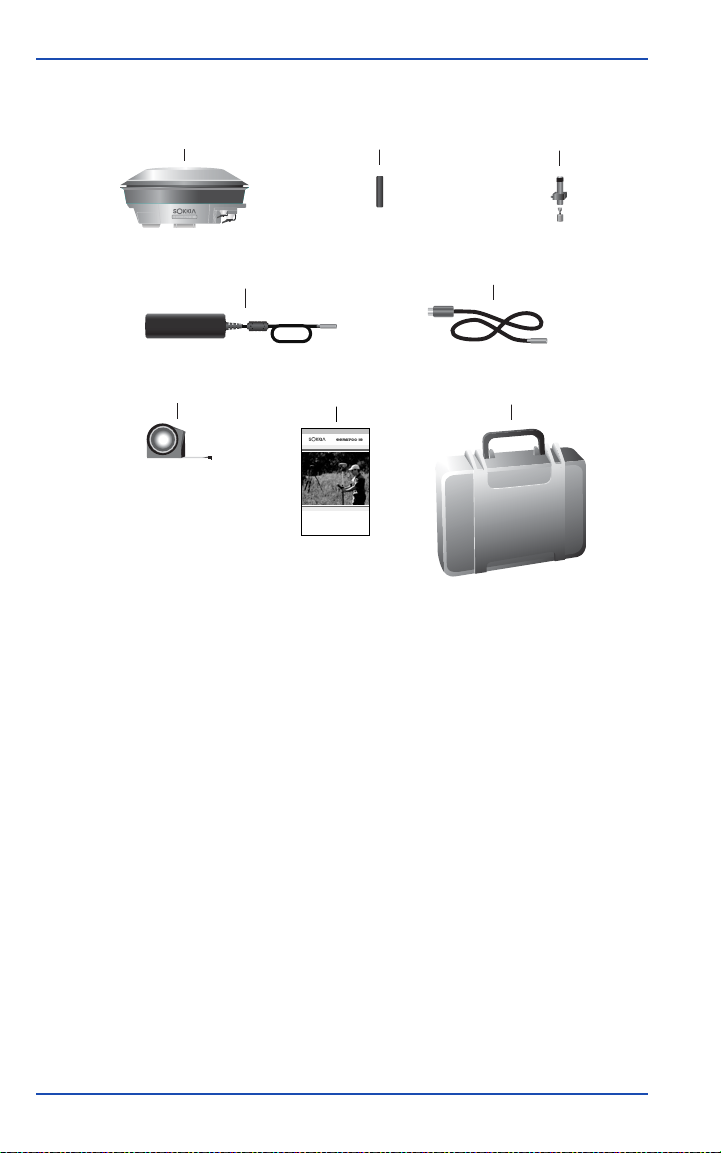
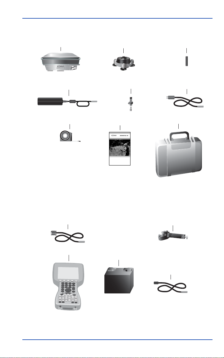
Standard rover components are illustrated in Figure 1, Standard
System Components: RTK Rover, page 4. Standard base
components are illustrated in Figure 2, Standard System
Components: RTK Base, page 5.
NOTE System components are illustrated with the assumption that an
internal radio is being used.
GSR2700 IS Operations Manual 3
Page 15
Chapter 1 Introduction
GPS Receiver
AC Adapter
Tape Measure
Internal Radio Antenna
PC Download Cable (USB)
Manual
GPS Receiver System
GSR2700 IS
Operations Manual
Quick Release
Hard Case
Figure 1: Standard System Components: RTK Rover
4 GSR2700 IS Operations Manual
Page 16
Introduction Chapter 1
r
GPS Receiver
AC Adapter
Tape Measure
Tribrach & Tribrach Adapto
Quick Release
Manual
GPS Receiver System
GSR2700 IS
Operations Manual
Internal Radio Antenna
PC Download Cable (USB)
Hard Case
Figure 2: Standard System Components: RTK Base
Figure 3 illustrates optional components that you may also wish
to use with your system.
PC Download Cable (Serial)
Data Collector Mounting Bracket
Data Collector
External Battery
External Battery Cable
Figure 3: Optional Components
GSR2700 IS Operations Manual 5
Page 17

Chapter 1 Introduction
1.4 Usage Cautions
CAUTION
• If your receiver has an internal radio, always ensure that the
radio antenna is properly connected to your receiver before
turning the unit on. Never disconnect the radio antenna
while the internal radio is still powered. Removal of the
antenna while the unit is powered may cause irreparable
damage to the internal circuitry of your radio, particularly
when the radio is transmitting information.
• This device incorporates circuitry to absorb most static
discharges. However, severe static shock may cause
inaccurate operation of the unit. Use anti-static precautions
where possible.
• This device is a precision instrument. Although it is
designed for rugged operating conditions, it performs best
when handled with care.
• When the port covers are closed, the enclosure is sealed to
provide protection against adverse environmental
conditions. To minimize the possibility of damage, always
keep the ports covered except when in use.
• The GSR2700 IS can accept an input supply voltage in the
range of +9 to +18 VDC. Do not operate the receiver
outside the specified voltage range.
• Drawing more than the specified maximum current (1 amp
combined total) from the two COM ports will cause an
internal fuse to interrupt the current to prevent damage to
the unit. If this happens, immediately reduce the load and
allow the unit to automatically reset its protection circuitry.
6 GSR2700 IS Operations Manual
Page 18
Introduction Chapter 1
1.5 Icons
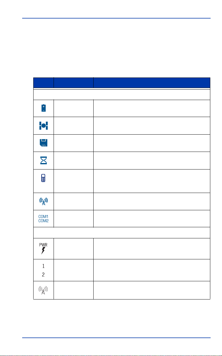
The GSR2700 IS uses the display panel and port icons
summarized in Table 2.
Table 2: Icon Summary
Icon Meaning Description & Task
Display Panel LEDs
Battery life Identifies the gauge that displays the available
internal and external battery power.
Ports
Satellite
tracking
Memory Identifies the gauge that displays the available
Occupation
timer
Bluetooth
communication
status
Internal radio
status
COM status Identifies the COM port status indicators.
PWR Identifies the power port on the underside of the
COM1,
COM2
Radio antenna Identifies the internal radio antenna connector on
Identifies the gauge that displays the number of
satellites currently being tracked by the receiver.
storage space in the internal memory.
Identifies the gauge that displays the static
occupation timer.
Identifies the Bluetooth communication status
indicators.
Identifies the internal radio status indicators.
GSR2700 IS.
Identifies the COM1 and COM2 ports on the
underside of the GSR2700 IS.
the underside of the GSR2700 IS.
GSR2700 IS Operations Manual 7
Page 19

Chapter 1 Introduction
1.6 Document Conventions
This manual uses notes and cautions to stress important
information.
NOTE A note contains text that further explains information in the
previous paragraph.
CAUTION
A caution provides information about
possible sources of difficulty or situations
that may cause damage to the product.
1.7 Finding More Information
This manual provides the information you need to use the
GSR2700 IS. The following documents provide supporting
documentation:
• Planning Reference Manual. Describes how to use Planning
software to help determine satellite availability, as well as
information about setting the POWERUP configuration for the
GSR2700 IS.
• Spectrum Survey Reference Manual. Provides information
about processing and adjusting your data using Spectrum
Survey.
• SDR+ User’s Guide. Describes how to use the SDR+ data
collection software.
8 GSR2700 IS Operations Manual
Page 20

Introduction Chapter 1
1.8 Obtaining Technical Assistance
Technical support is available from the distributor where you
purchased this product. When you contact technical support,
please make sure you have the following information:
• Your receiver information, including: serial number, part
number, model, firmware version, and internal radio
information
• A concise description of the problem
For a list of SOKKIA worldwide offices, see the list at the back of
this manual.
GSR2700 IS Operations Manual 9
Page 21

GSR2700 IS
Chapter 2
The GSR2700 IS enclosure is fully sealed, and houses your
system’s GPS receiver, GPS antenna, batteries, memory, internal
radio (if installed), and wireless communication device. The
integration of components into a single unit makes the use of a
backpack unnecessary.
2.1 Enclosure Features
The top of the GSR2700 IS is comprised of the GPS antenna and
radome, surrounded by a shock-absorbing protective bumper.
On the side of the receiver is the display panel, which enables
you turn on and monitor the system. Brightly colored LEDs
display the status of your system. (See Figure 4.) For details about
the display panel, see Section 2.9, Display Panel, page 18.
Components
Figure 4: GPS Antenna and Display Panel
10 GSR2700 IS Operations Manual
Page 22

GSR2700 IS Components Chapter 2
The ports are accessible from the underside of the unit. See
Figure 5 for a view of the ports with covers. For details about the
ports, see Section 2.2, Ports, page 12.
Figure 5: Ports
The underside of the GSR2700 IS enclosure has a standard 5/8”
survey mount, compatible with a standard quick release fitting,
for mounting the unit on a tripod or survey pole. The mounting
socket accepts a threaded stud up to 0.75” (19 mm) in length.
Also on the underside of the enclosure is a phase center offset
label. See Figure 6 for a view of the mounting socket and phase
center offset label.
Figure 6: Mounting Socket and Phase Center Offset Label
The internal antenna for the Bluetooth wireless communication
device is indicated on the underside of the enclosure by a square
raised area (see Figure 7). For details about the wireless
GSR2700 IS Operations Manual 11
Page 23

Chapter 2 GSR2700 IS Components
communication device, see Section 2.8, Wireless Communication,
page 17.
Figure 7: Wireless Communication Antenna
2.2 Ports
The GSR2700 IS features an external power input port, two
communication ports, and an antenna connector port for the
internal radio. All ports are located on the underside of the
enclosure and are protected from dust and water by covers.
NOTE Leave the port covers closed unless a port is in use.
Each port is labeled with an icon and text for easy identification.
See Figure 8 for an illustration of the ports and labels. See Table 3,
Port Summary, page 13 for a description of each port.
1
2
Figure 8: Ports and Labels
43
12 GSR2700 IS Operations Manual
Page 24

GSR2700 IS Components Chapter 2
Table 3: Port Summary
Number Description
1 Antenna port (internal radio)
2 COM1 port (handheld communication)
3 COM2 port (radio and USB
communication)
4
Power port
2.2.1 Antenna port
The GSR2700 IS has an external TNC antenna connector for an
internal UHF or GSM radio (if installed). See Figure 9 for a view
of the receiver with radio antenna attached. For more information
about the internal radio, see Section 2.7, Internal Radio, page 17.
Figure 9: Internal Radio Antenna
CAUTION
Attach only the Sokkia antenna (UHF or
GSM, as applicable) to the antenna port. Do
not attach other antennas.
GSR2700 IS Operations Manual 13
Page 25

Chapter 2 GSR2700 IS Components
2.2.2 Power port and power input
The GSR2700 IS has one power input port for connecting an
external power source to the receiver, such as an external battery,
as an alternative to using the internal batteries. See Section 2.4,
Batteries, page 15 for more information about the internal
batteries, and Section 5.2, Power Source, page 42 for more
information about power input.
2.2.3 Communication ports
The two communication ports enable you to communicate with
accessory devices, such as a data collector or radio. As well, each
communication port provides a power output for powering
accessory devices (for example, an external UHF radio).
Typically, the COM1 port is intended for use with a data collector.
The COM2 port is typically intended for use with a radio. You
can also connect your PC’s USB port to the COM2 port for highspeed data transfer from internal memory.
The GSR2700 IS can provide power output through the COM1
and COM2 ports for powering accessories. The output voltage
from the COM port is approximately the same as the input to the
unit. For more information about powering peripheral devices,
see Section 5.3, Powering Peripheral Devices, page 44.
2.3 Cables
Each GSR2700 IS cable connector is keyed to ensure that the cable
can be inserted in only one way, to prevent damage to both the
GSR2700 IS and the cables. In addition, the connectors that are
used to secure the cables to the receiver have a latching
mechanism that requires careful insertion and removal.
Cables are color coded according to the port they connect to (red
for the power port, blue for the COM1 port, and white for the
COM2 port). Both the cable and the corresponding port on the
receiver indicate the appropriate color.
14 GSR2700 IS Operations Manual
Page 26

GSR2700 IS Components Chapter 2
Observe the following when handling cables:
• Before inserting the cable, ensure you are using the
appropriate cable for the port. Check the color coding on the
cable and the port itself to ensure they match.
• Line up the red dot on the connector shell with the red index
mark on the receiver’s receptacle.
• Insert the connector until it seats with a click; it is now locked
in place.
• To remove a cable, grasp the connector by the knurled ring
and pull.
CAUTION
Do not pull directly on the cable.
2.4 Batteries
The GSR2700 IS incorporates two internal custom Li-Ion battery
packs. The GSR2700 IS can also be powered using an external
power source. See Section 5.2, Power Source, page 42 for more
information about power input.
The internal batteries will power the unit continuously for about
10 hours as part of an RTK rover setup, using a UHF internal
radio. When operating without a radio, the receiver can be
operated for about 14 hours on the internal batteries.
The internal batteries are designed for optimal use for the first
300 discharge cycles. If, after using the receiver for some time,
you notice degraded battery life, contact your local Sokkia
distributor.
NOTE The internal batteries should be serviced by your local Sokkia
distributor. Do not attempt to service the batteries yourself—
doing so will void the product warranty.
GSR2700 IS Operations Manual 15
Page 27

Chapter 2 GSR2700 IS Components
2.5 Memory
The GSR2700 IS comes standard with 64 MB of internal memory
to support post-processing applications. For information about
how many hours of data can be stored in memory, see Section 6.5,
Data Storage Capacity, page 54.
NOTE To determine the memory capacity of your receiver, use
Spectrum Survey or SDR+. If the internal memory needs to be
serviced or upgraded, see your local Sokkia distributor.
2.6 GPS Antenna
The GSR2700 IS features an integrated GPS antenna (L1/L2) with
Pinwheel™ technology. This patented antenna provides
exceptional multipath rejection and performance equivalent to a
typical choke ring antenna.
Figure 10: GPS Antenna
There is one tape measure anchor point on the circumference of
the receiver from which the antenna height can be measured.
This height measurement location enables the use of a Sokkia
tape measure (custom tape with offset scale and reference tip) or
a typical hardware store tape measure.
A phase center offset label is located on the underside of the
receiver (see Figure 6, Mounting Socket and Phase Center Offset
Label, page 11 for details).
16 GSR2700 IS Operations Manual
Page 28

GSR2700 IS Components Chapter 2
2.7 Internal Radio
Depending on your particular system configuration, the GSR2700
IS may include an internal UHF or GSM/GPRS radio for
transmitting or receiving differential corrections for RTK
applications.
The radio antenna connects on the underside of the receiver; see
Section 2.2.1, Antenna port, page 13 for details.
NOTE If your receiver has an internal GSM radio, contact your local
Sokkia distributor to install the SIM card supplied by your
telecommunications service provider.
CAUTION
Always ensure that the radio antenna is
properly connected to your receiver before
turning the unit on. Never disconnect the
radio antenna while the internal radio is still
powered. Removal of the antenna while the
unit is powered may cause irreparable
damage to the internal circuitry of your
radio, particularly when the radio is
transmitting information.
See Radio Link, page 58 for details about the UHF and GSM/
GPRS internal radios.
2.8 Wireless Communication
The GSR2700 IS features a built-in Class 2 Bluetooth wireless
communication device, which enables a wireless connection from
a Bluetooth-enabled data collector or a PC.
GSR2700 IS Operations Manual 17
Page 29

Chapter 2 GSR2700 IS Components
2.9 Display Panel
The GSR2700 IS has an easy-to-use display panel with singlebutton operation and LED display indicators that give you a
view of your system status. See Chapter 3, Display Panel
Operations, page 19 for details about display panel features and
how to use them.
2.10 Audible Annunciator
The GSR2700 IS features an audible annunciator, which issues a
series of voice messages or sounds to alert you of the receiver’s
current status during operation. For details about the audible
annunciator, see Section 3.4, Audible Annunciator, page 31.
18 GSR2700 IS Operations Manual
Page 30
Display Panel
Chapter 3
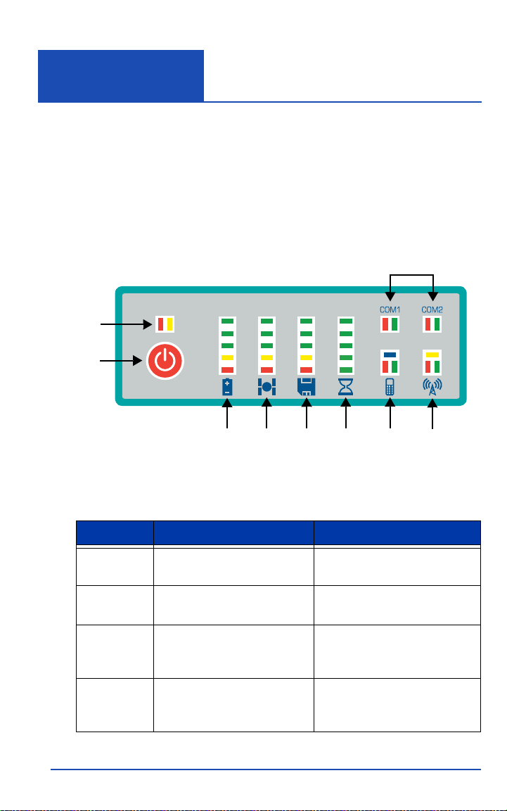
The GSR2700 IS LED display panel provides receiver health
information, including battery life, memory available, satellites
tracked, and port and radio activity. In addition to the visual
display, a series of voice messages or sounds alert you to receiver
status and event conditions.
Figure 11 illustrates the display panel components, and Table 4
describes each component.
2
1
Operations
3
7 8 9
6
Figure 11: Display Panel Components
Table 4: Display Panel Components
Component Description Reference
1 Power button Section 3.1, Power Button,
page 20
2 Receiver health indicator Section 3.2.1, Receiver
3 COM port communication
status indicators
4 Wireless communication
status indicator
GSR2700 IS Operations Manual 19
health, page 23
Section 3.2.2, COM port
communication status,
page 24
Section 3.2.3, Wireless
communication status,
page 25
4
5
Page 31
Chapter 3 Display Panel Operations
Table 4: Display Panel Components (continued)
Component Description Reference
5 Internal radio status indicator Section 3.2.4, Internal radio
status, page 26
6 Battery life gauge Section 3.3.1, Battery life
gauge, page 27
7 Satellite tracking gauge Section 3.3.2, Satellite
8 Memory gauge Section 3.3.3, Memory gauge,
9 Occupation timer gauge Section 3.3.4, Occupation
tracking gauge, page 28
page 29
timer gauge, page 30
3.1 Power Button
The power button is used to turn the unit on or off,
format the internal memory, or perform a factory reset.
The power button provides single-button operation for the
receiver. The number of seconds that the power button is held
determines how the receiver will behave. At each time interval,
the receiver issues voice messages or sounds to guide you
through the process. See Section 3.4, Audible Annunciator, page 31
for more information about voice messages and sounds.
NOTE Ensure that you hold the power button firmly for the entire
duration that is required to perform the desired action.
20 GSR2700 IS Operations Manual
Page 32
Display Panel Operations Chapter 3
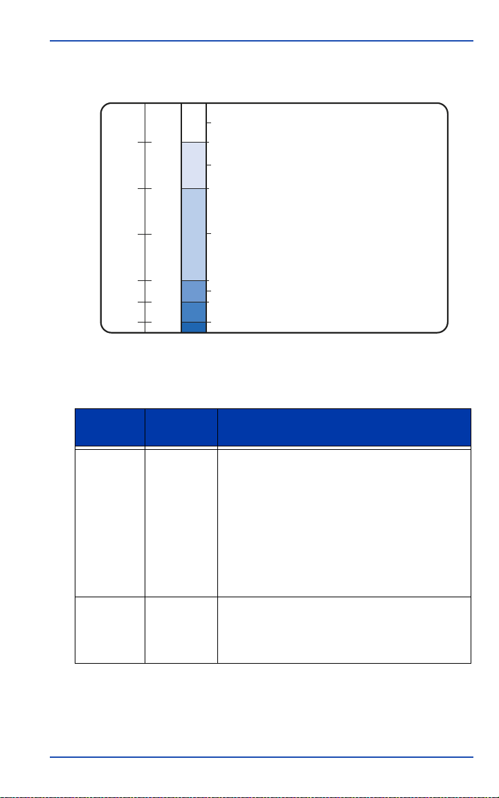
The power button functions are illustrated in Figure 12 and
summarized in Table 5.
25
20
15
Time Line (seconds)
10
3
1
Release to return to normal operation
(no action taken)
Release during this period to erase memory
(20-25 seconds)
Release during this period to factory reset
(10-20 seconds)
Power off (3-10 seconds)
Power on (1 second)
Figure 12: Power Button Functions
Table 5: Power Button Functions
Number of
Action
Turn on 1 Hold the button for 1 second and release to turn
Seconds
Description
the receiver on. The battery life gauge indicates
the progress of the startup sequence.
After startup (approximately 20 seconds), the
battery life gauge indicators will turn off for a
short period of time, and the “Receiver Ready”
message or sound will be issued to indicate that
the system is operational.
Note: The receiver health indicator LEDs might
illuminate during startup—this is normal.
Turn off 3 Hold the button for 3 seconds until the “Power
Off” message or sound is issued and the top
three battery life gauge indicators illuminate.
Release the button to turn off the receiver.
GSR2700 IS Operations Manual 21
Page 33

Chapter 3 Display Panel Operations
Table 5: Power Button Functions (continued)
Number of
Action
Seconds
Description
Factory
reset
Erase
memory
Disregard 25 If you hold the button longer than 25 seconds
10 With the receiver turned on, hold the button for
10 seconds until the “Factory Reset” message
or sound is issued and the top three LEDs on the
battery life, satellite tracking, and memory
gauges illuminate. Release the button to reset all
stored parameters on the receiver to their default
values.
Note: This action is not reversible.
20 With the receiver turned on, hold the button for
20 seconds until the “Delete Files” message or
sound is issued and the top three LEDs on the
memory gauge illuminate. Release the button to
delete all the files from the memory.
Note: This action is not reversible. If you are
unsure about whether you want to delete all the
files, hold the button longer than 25 seconds so
that the receiver simply returns to normal
operations.
To delete individual files from the memory, use
Sokkia software on your PC.
until the “Continue Operation” message or sound
is issued, no action will be taken, and the
receiver will return to normal operations. The
receiver will not turn off, the data files will not be
erased, and the settings will not revert to factory
settings.
3.2 Status Indicators
The GSR2700 IS display panel features status indicators to
provide information about the following:
• Receiver health (Section 3.2.1, Receiver health, page 23)
• COM port communication status (Section 3.2.2, COM port
communication status, page 24)
22 GSR2700 IS Operations Manual
Page 34

Display Panel Operations Chapter 3
• Wireless communication status (Section 3.2.3, Wireless
communication status, page 25)
• Internal radio status (Section 3.2.4, Internal radio status,
page 26)
3.2.1 Receiver health
The receiver health indicator displays the current status of
the receiver.
Under normal operation, neither LED is illuminated. When there
is a warning or error condition, the LEDs illuminate in a sequence
of six flashes. If the first flash in the sequence is yellow, it is a
warning condition; if red, it is an error condition. The particular
combination of red and yellow flashes indicates a specific
warning or error condition (for example, the receiver is being
operated outside its temperature range).
If an error condition persists, take the following steps:
1. Turn the receiver off for a few minutes.
2. Perform a factory reset (see Table 5, Power Button Functions,
page 21).
3. If the error condition still persists, check to see if the receiver
is too hot. If it is, let it cool down and perform another factory
reset.
4. If the error condition is not resolved, contact your local
Sokkia distributor.
NOTE Make note of the sequence of flashes and provide this
information to your Sokkia distributor, to assist in identifying the
problem.
GSR2700 IS Operations Manual 23
Page 35
Chapter 3 Display Panel Operations
3.2.2 COM port communication status
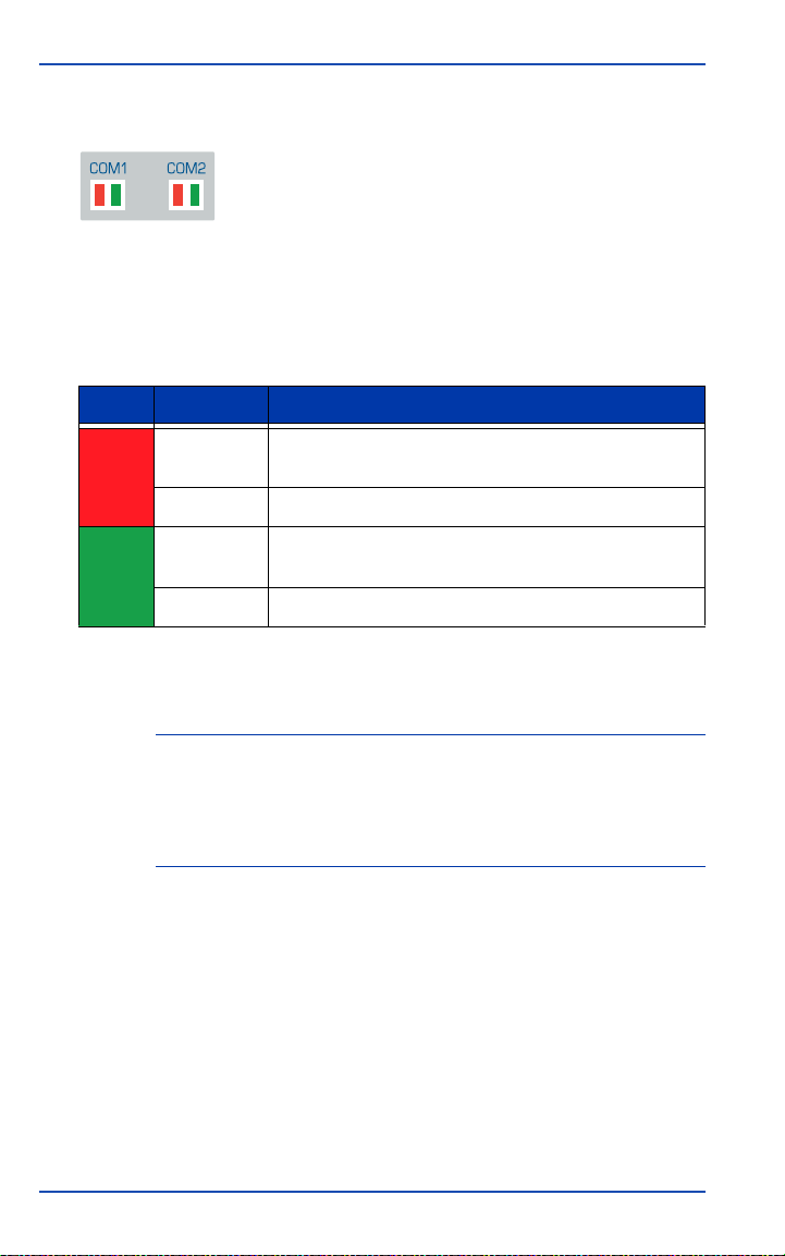
The COM port communication status indicators
display the status of communication traffic flow
across the receiver’s COM1 and COM2 ports.
The LEDs blink to indicate signal sent/received on the respective
port. See Table 6 for a description of the COM port
communication status LEDs.
Table 6: COM Port Communication Status LEDs
LED State Status Description
Red Illuminated Data is being received by the GSR2700 IS via the
COM port.
Dark No data is being received via the COM port.
Green Illuminated Data is being transmitted from the GSR2700 IS via
the COM port.
Dark No data is being transmitted via the COM port.
If data is simultaneously being transmitted and received, both
transmit and receive LED indicators will be illuminated.
NOTE During typical RTK operation, when a data collector is
connected to COM1, both red and green LEDs illuminate
frequently. When an external UHF radio is connected to COM2,
the red LED illuminates when operating the receiver as a rover,
and the green LED illuminates when operating it as a base.
For details about the COM ports, See Section 2.2.3, Communication
ports, page 14.
24 GSR2700 IS Operations Manual
Page 36
Display Panel Operations Chapter 3
3.2.3 Wireless communication status
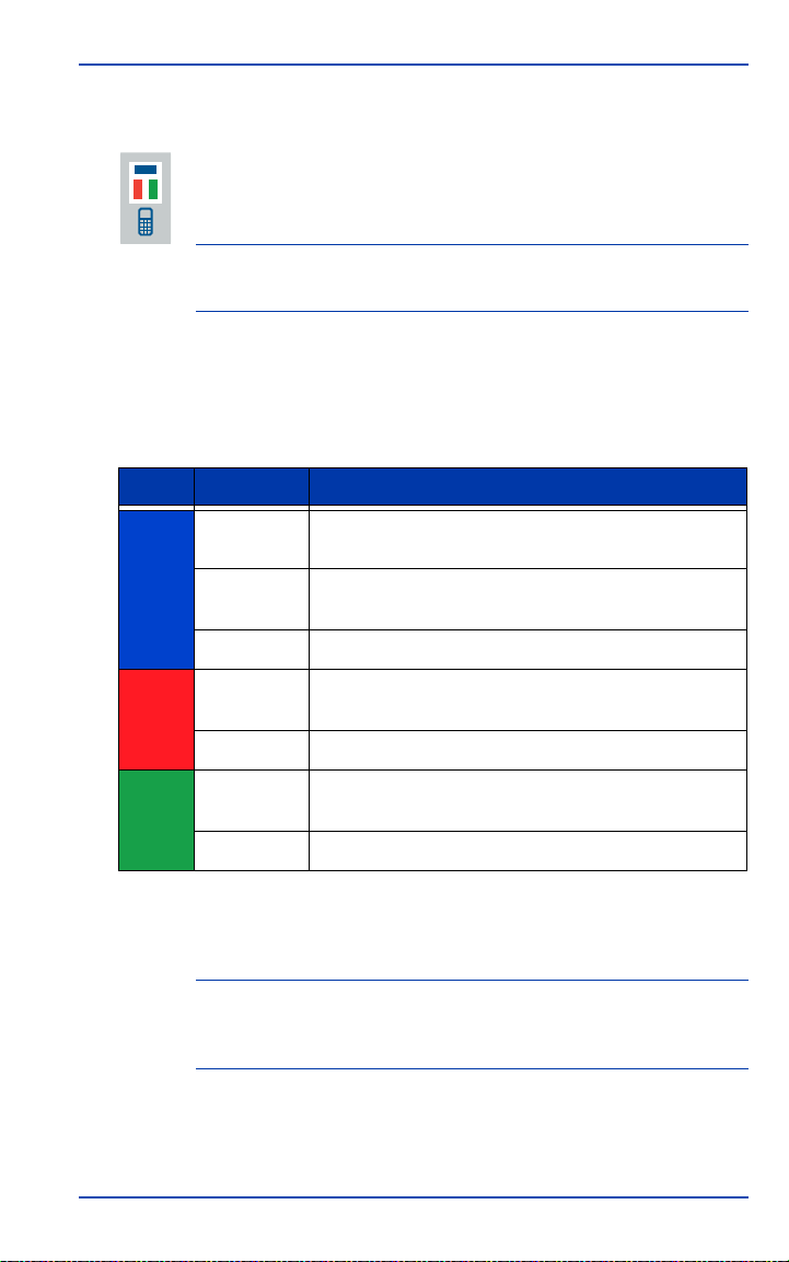
The wireless communication status indicators indicate the
status of the Bluetooth connection and activity on the
internal Bluetooth port.
NOTE The internal Bluetooth device powers off if there is no
connection made within 30 minutes.
See Table 7 for a description of the wireless communication status
LEDs.
Table 7: Wireless Communication Status LEDs
LED State Status Description
Blue Blinking A connection with another device has not yet been
established.
Solid A Bluetooth connection has been established with
another device (for example, a data collector).
Dark The internal Bluetooth device is powered off.
Red Blinking Data is being received by the GSR2700 IS via the
Dark No data is being received via the Bluetooth port.
Green Blinking Data is being transmitted via the GSR2700 IS
Dark No data is being transmitted via the Bluetooth port.
Bluetooth port.
Bluetooth port.
If data is simultaneously being transmitted and received, both
transmit and receive LED indicators are illuminated.
NOTE During typical RTK operation, when a data collector is
connected to the internal Bluetooth port, both red and green
LEDs illuminate frequently.
For details about the wireless communication device, see Section
2.8, Wireless Communication, page 17.
GSR2700 IS Operations Manual 25
Page 37
Chapter 3 Display Panel Operations
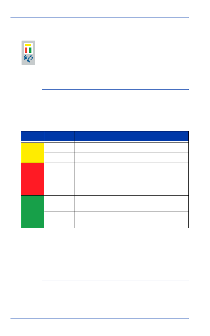
3.2.4 Internal radio status
If your receiver has an internal radio module, the internal
radio status indicators display the power and activity
status of the internal UHF or GSM radio.
NOTE The internal radio powers off if there is no communication within
30 minutes.
See Table 8 for a description of the internal radio communication
status LEDs.
Table 8: Internal Radio Status LEDs
LED State Status Description
Yellow Illuminated Power is being provided to the internal radio device.
Dark The internal radio is powered off.
Red Blinking Data is being received by the GSR2700 IS via the
internal radio device.
Dark No data is being received via the internal radio
Green Blinking Data is being transmitted from the GSR2700 IS via
Dark No data is being transmitted via the internal radio
device.
the internal radio device.
device.
If data is simultaneously being transmitted and received, both
transmit and receive LED indicators are illuminated.
NOTE When the internal radio is being used, the red LED illuminates
when operating the receiver as a rover, and the green LED
illuminates when operating it as a base.
For details about the internal radio, see Section 2.7, Internal Radio,
page 17.
26 GSR2700 IS Operations Manual
Page 38

Display Panel Operations Chapter 3
3.3 Gauges
The GSR2700 IS display panel features four gauges to provide
information about the following:
• Battery life and charging status (Section 3.3.1, Battery life gauge,
page 27)
• Satellites currently being tracked (Section 3.3.2, Satellite
tracking gauge, page 28)
• Memory available (Section 3.3.3, Memory gauge, page 29)
• Occupation time (period of continuous data of sufficient
quality for post-processing) (Section 3.3.4, Occupation timer
gauge, page 30)
Each gauge contains a series of five LEDs that illuminate to alert
you of the system’s status.
NOTE During typical operation, only one LED is illuminated on each
gauge at any one time.
3.3.1 Battery life gauge
The battery life gauge displays the battery life remaining
on the internal batteries. When an external power source
is connected, the detected available voltage is indicated by
a blinking LED. When the receiver is powered off and is
connected to the AC Adapter, the charging status is
indicated.
The internal battery life is calculated to an accuracy of ±10%. The
external battery life is calculated to an accuracy of ±0.1 volts.
GSR2700 IS Operations Manual 27
Page 39
Chapter 3 Display Panel Operations
Table 9 summarizes the values indicated by each LED for internal
and external batteries, and charging status.
Table 9: Battery Life Gauge Indicators
Internal Battery
Time Remaining
(hours)
LED
Top at least 9 11.3 to 18.0 Blinking: receiver charging
4 6 to 9 10.9 to 11.3 not applicable
3 3 to 6 10.6 to 10.9 not applicable
2 1 to 3 10.1 to 10.6 not applicable
1 0 to 1 <10.1 not applicable
a. When receiver is powered off and connected to the AC Adapter.
External Battery
Power Available
(VDC)
Charging Status
Solid: charging complete
a
When the internal batteries have full charge, the top LED (green)
is illuminated. The bottom LED (red) is illuminated when you
have less than one hour of battery power remaining.
When the receiver is off and the batteries are charging, the top
LED blinks; the LED stops blinking when charging is complete.
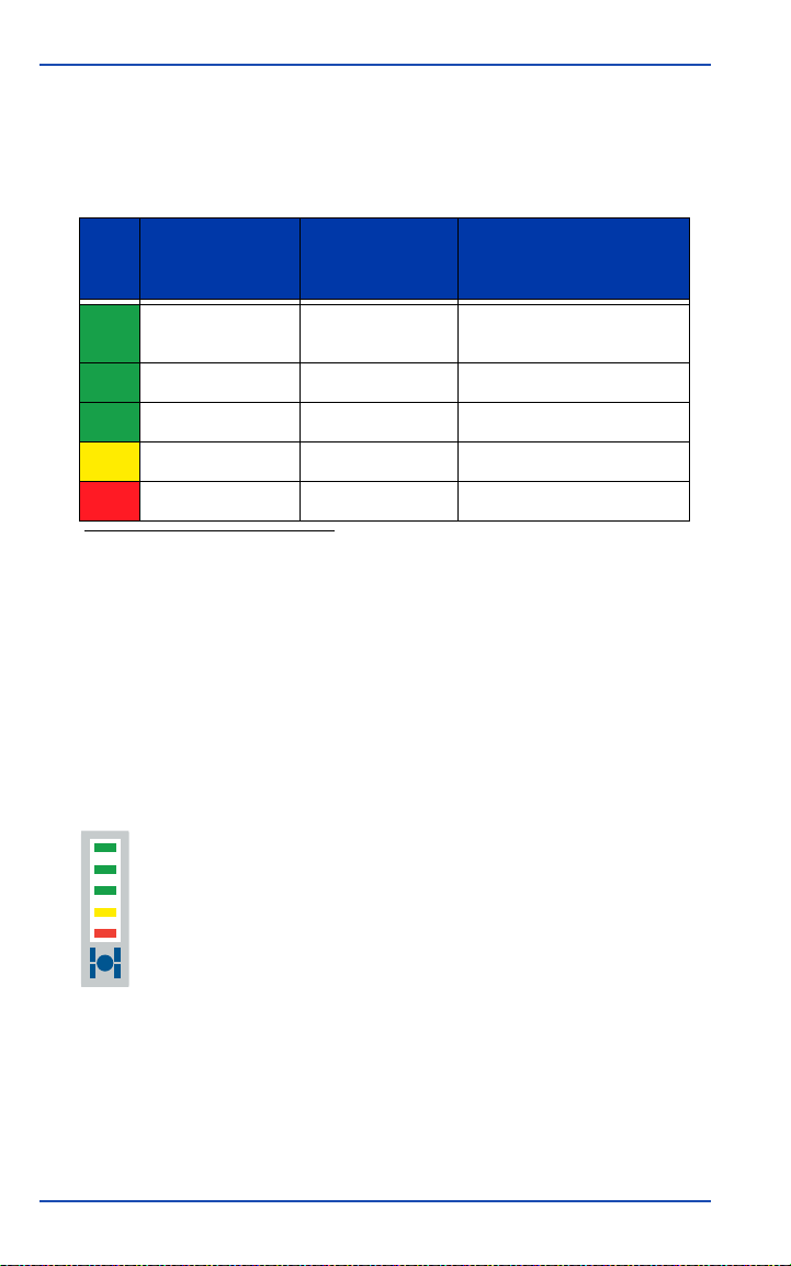
3.3.2 Satellite tracking gauge
The satellite tracking gauge displays the number of
satellites currently being tracked by the receiver. If the
current position of the receiver is being held fixed,
consistent with RTK base operation, the currently
illuminated LED will blink.
For a satellite to be counted as used, it must have a healthy signal
and be above the elevation mask, and the receiver must have
achieved lock (both code and carrier).
28 GSR2700 IS Operations Manual
Page 40
Display Panel Operations Chapter 3
Table 10 summarizes the values indicated by each LED.
Table 10: Satellite Tracking Gauge Indicators
Number of
Satellites Being
Tracked
LED
Top 10, 11, or 12
4 8 or 9
3 6 or 7
2 4 or 5
1 1, 2, or 3
For the most accurate survey results, perform surveys with a
minimum of six satellites if possible. The bottom LED (red) is
illuminated if the receiver is using only one, two, or three
satellites, which are insufficient for three-dimensional
positioning applications.
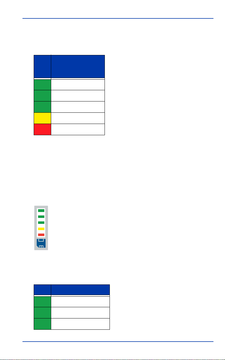
3.3.3 Memory gauge
The memory gauge displays the amount of available
memory. When data is being logged to a file, the currently
illuminated LED blinks.
Table 11 summarizes the values indicated by each LED.
Table 11: Memory Gauge Indicators
LED Available Memory (%)
Top 80 to 100
4 60 to 80
3 40 to 60
GSR2700 IS Operations Manual 29
Page 41
Chapter 3 Display Panel Operations
Table 11: Memory Gauge Indicators (continued)
LED Available Memory (%)
2 20 to 40
1 0 to 20
When the memory has over 80% space available, the top LED
(green) is illuminated. The bottom LED (red) is illuminated if the
memory is almost full. When the red LED is illuminated,
consider deleting files to free up space.
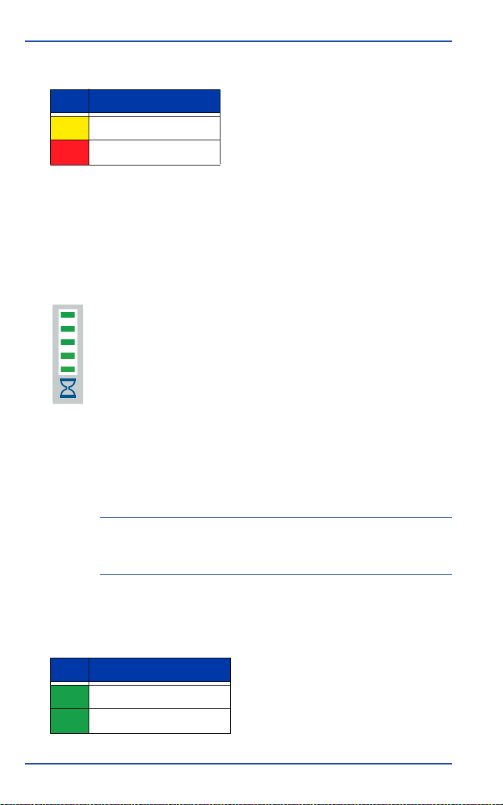
3.3.4 Occupation timer gauge
The occupation timer gauge indicates that sufficient
quality and quantity of data has been collected for
successful static data post-processing for the indicated
length of baseline.
If an LED is illuminated, it indicates that you have now collected
sufficient raw GPS data to successfully post-process a baseline of
the indicated baseline length. When insufficient data has been
collected to theoretically process a baseline of 5 kilometers, none
of the LED indicators will be illuminated.
NOTE For successful post-processing, it is assumed that there are no
adverse environmental conditions and you have a data logging
interval of 10 seconds.
Table 12 summarizes the values indicated by each LED.
Table 12: Occupation Timer Gauge Indicators
LED Baseline Length (km)
Top up to 30
4 up to 20
30 GSR2700 IS Operations Manual
Page 42

Display Panel Operations Chapter 3
Table 12: Occupation Timer Gauge Indicators (continued)
LED Baseline Length (km)
3 up to 15
2 up to 10
1 up to 5
NOTE Table 12 provides estimates only. Performance of the indicator
depends on excellent quality GPS data being observed at other
receivers (no obstructions, same satellites, low multipath, etc.).
If you are uncertain about the quality of the data collected, log
data for a longer period of time.
3.4 Audible Annunciator
The GSR2700 IS is equipped with an audible annunciator, which
issues a series of voice messages or sounds to alert you to the
system status and event conditions.
NOTE Your receiver is preconfigured with either voice messages or
sounds, at a preset volume. If you wish to make any changes to
the voice messages or sounds, or the volume levels, contact
your local Sokkia distributor. (You can also choose to have no
messages or sounds.)
The frequency of the voice message or sound depends on the
specific condition. The frequency is either once (when the
condition first occurs) or continuous (repeats every 30 seconds
for as long as the condition persists).
GSR2700 IS Operations Manual 31
Page 43

Chapter 3 Display Panel Operations
The annunciator indicates the conditions summarized in
Table 13.
Table 13: Audible Annunciator Conditions
Status/Event
Condition
Description Frequency
Receiver Ready The receiver has completed its startup
Power Off The power button has been held down
Receiver Shutting
Down
Factory Reset The power button has been held down
Delete Files The power button has been held down
Continue Operation The power button has been held down
Battery Low The remaining battery life (internal or
sequence, and is ON and ready for
operation. Initiated whenever you
initially press the power button to power
on the receiver.
long enough to power off the receiver.
The receiver is turning off, initiated by
pressing the power button for the
appropriate length of time. This can also
occur when the batteries are sufficiently
discharged.
long enough to initiate a factory reset of
the receiver.
long enough to initiate erasing of all of
the files in memory.
too long for any action to take place.
Release the power button to resume
normal receiver operations.
external batteries) is less than 15
minutes.
Note: This is only an estimate. To
ensure continued operation without
interruption, immediately connect a
valid external power source.
once
once
once
once
once
once
continuous
Memory Low The remaining memory is less than 15
minutes under the current logging
conditions. When the memory is full,
data will no longer be stored.
continuous
32 GSR2700 IS Operations Manual
Page 44

Display Panel Operations Chapter 3
Table 13: Audible Annunciator Conditions (continued)
Status/Event
Condition
Description Frequency
Memory Full A file is open for data logging on the
receiver, but the memory is full and new
data can no longer be stored.
RTK Fixed A fixed-integer RTK solution has been
achieved.
Fix Lost A fixed-integer RTK solution has been
lost.
continuous
once
once
GSR2700 IS Operations Manual 33
Page 45

Chapter 4
Setting up the GSR2700 IS is a straightforward process, whether
you are in the field (collecting data), or back at the office
(configuring the receiver or transferring collected data to your PC
for post-processing).
This chapter summarizes system setup for both the office and
field operations.
See Section 1.7, Finding More Information,
page 8 for a list of items you should be
aware of as you set up and use the
GSR2700 IS.
System Setup
CAUTION
4.1 Setting Up at the Office
An office setup can be used to configure the GSR2700 IS or to
transfer collected data from the receiver to a PC.
The GSR2700 IS supports transfer of data from the receiver’s
memory to a PC in the following ways:
• Via a USB connection to the receiver’s COM2 port
• Using a Bluetooth connection
• Using a serial connection to the receiver’s COM1 port
To set up the GSR2700 IS in the office, complete the following
steps:
1. Place the GSR2700 IS on a desk or other suitable work
surface.
2. Use the USB PC Download cable to connect the PC to the
receiver’s COM2 (white) port (see Chapter 2, GSR2700 IS
Components, page 10).
or
34 GSR2700 IS Operations Manual
Page 46

System Setup Chapter 4
Use a serial PC Data cable to connect the PC to the receiver’s
COM1 (blue) port (see Chapter 2, GSR2700 IS Components,
page 10).
NOTE Or, if you are using a Bluetooth connection, proceed to step 3.
3. Turn on the GSR2700 IS (see Chapter 5, Basic Operations,
page 42).
4. If using a Bluetooth connection, connect from the PC to the
receiver.
5. Communicate with the GSR2700 IS using the Planning
software (refer to your Planning Reference Manual) to set up
the POWERUP configuration, or any Sokkia software (for
example, Spectrum Survey) to transfer data to the PC.
4.2 Setting Up for Field Operations
The GSR2700 IS can be used for static or kinematic surveys, as
well as for real-time kinematic (RTK) surveys as a base or rover.
This section provides an overview of the equipment and setup
for typical uses of the system.
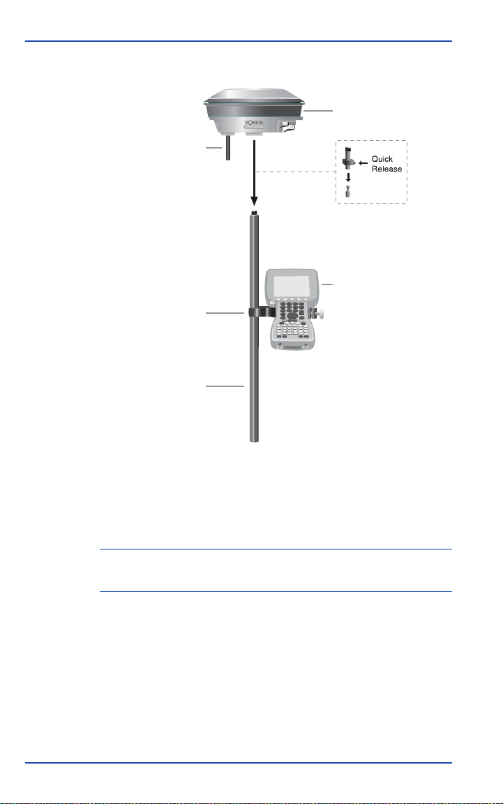
4.2.1 Typical RTK rover setup
A typical rover RTK setup consists of a range pole, GSR2700 IS
receiver with internal GSM or UHF radio, and data controller. If
you use a Bluetooth connection to communicate between the data
controller and the receiver, you do not require any cables at all.
Typical rover setups include using one of the following to receive
corrections:
• Internal UHF radio
• Internal GSM/GPRS radio used in one-to-one mode (for
example, one GSR2700 IS receiver to another)
• Internal GSM/GPRS radio used via the Internet (for example,
to a GSR2700 RS, or NTRIP base station)
GSR2700 IS Operations Manual 35
Page 47
Chapter 4 System Setup
See Figure 13 for an illustration of a typical rover setup.
GSR2700 IS Receiver
Internal Radio Antenna
Data Collector
Data Collector Mounting Bracket
Range Pole
Figure 13: Typical RTK Rover Setup
For RTK rover setup, complete the following steps:
1. Mount the GSR2700 IS on the pole.
NOTE Position the receiver with the GPS antenna up and the
mounting socket down.
2. If you are using the internal radio, ensure that the internal
radio antenna is connected to the receiver’s antenna port
36 GSR2700 IS Operations Manual
Page 48

System Setup Chapter 4
3. Ensure that the internal radio antenna is connected to the
receiver’s antenna port (see Section 2.7, Internal Radio,
page 17).
CAUTION
Always ensure that the radio antenna is
properly connected to your receiver before
turning the unit on. Never disconnect the
radio antenna while the internal radio is still
powered. Removal of the antenna while the
unit is powered may cause irreparable
damage to the internal circuitry of your
radio, particularly when the radio is
transmitting information.
4. Turn on the receiver (see Chapter 5, Basic Operations,
page 42).
5. Use a Bluetooth connection, or serial communication via the
receiver’s COM1 (blue) port, to connect a data collector to the
receiver (see Chapter 2, GSR2700 IS Components, page 10).
4.2.2 Typical RTK base setup
A typical RTK base station setup consists of a tripod and the
GSR2700 IS receiver with internal UHF or GSM/GPRS radio. The
setup might also include a data collector for in-field
configuration of the receiver.
Typical base setups include using one of the following to transmit
corrections:
• Internal UHF radio
• Internal GSM/GPRS radio used in one-to-one mode (for
example, one GSR2700 IS receiver to another)
• External radio device (for example, a cell phone or high-
power radio)
GSR2700 IS Operations Manual 37
Page 49
Chapter 4 System Setup
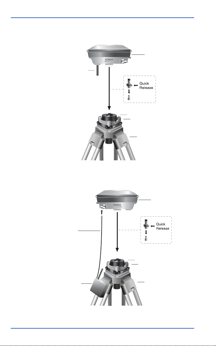
See Figure 14 and Figure 15 for illustrations of two typical base
setups.
GSR2700 IS
Receiver
Internal Radio Antenna
Tribrach Adapter
Tribrach
Tripod
Figure 14: Typical RTK Base Setup (internal radio)
GSR2700 IS
Receiver
External Radio Cable
Tribrach Adapter
Tribrach
External Radio
Tripod
Figure 15: Typical RTK Base Setup (external radio)
38 GSR2700 IS Operations Manual
Page 50

System Setup Chapter 4
For RTK base setup, complete the following steps:
1. Mount the GSR2700 IS on the tripod.
NOTE Position the receiver with the GPS antenna up and the
mounting socket down.
2. If you don’t plan to use a data collector in the field, ensure
you have the appropriate POWERUP configuration loaded
onto the receiver (see Chapter 6, Collecting Data, page 48).
3. If you are using the internal radio, ensure that the internal
radio antenna is connected to the receiver’s antenna port (see
Section 2.7, Internal Radio, page 17).
CAUTION
Always ensure that the radio antenna is
properly connected to your receiver before
turning the unit on. Never disconnect the
radio antenna while the internal radio is still
powered. Removal of the antenna while the
unit is powered may cause irreparable
damage to the internal circuitry of your
radio, particularly when the radio is
transmitting information.
4. If you are using an external radio device:
• Ensure the antenna is connected to the radio device.
• Connect power to the radio device.
• Use a radio communications cable to connect the device to
the receiver’s COM2 (white) port (see Chapter 2,
GSR2700 IS Components, page 10).
5. Turn on the receiver (see Chapter 5, Basic Operations,
page 42).
6. (Optional) Use a Bluetooth connection, or serial
communication via the receiver’s COM1 (blue) port, to
connect a data collector to the receiver (see Chapter 2,
GSR2700 IS Components, page 10).
GSR2700 IS Operations Manual 39
Page 51
Chapter 4 System Setup
7. Check the satellite tracking gauge to verify that the position
is fixed (see Section 3.3.2, Satellite tracking gauge, page 28 for
more information).
8. Check the internal radio status indicator (see Section 3.2.4,
Internal radio status, page 26) or COM2 status indicator
Section 3.2.2, COM port communication status, page 24), as
appropriate, to verify that corrections are being transmitted
(green LED).
NOTE If you are using SDR+ software and have a valid RTK-capable
POWERUP configuration loaded on your receiver, you do not
need to connect GSR2700 IS to a data collector to use the
receiver as a base. See the SDR+ User’s Guide for more
information.
4.2.3 Typical static setup
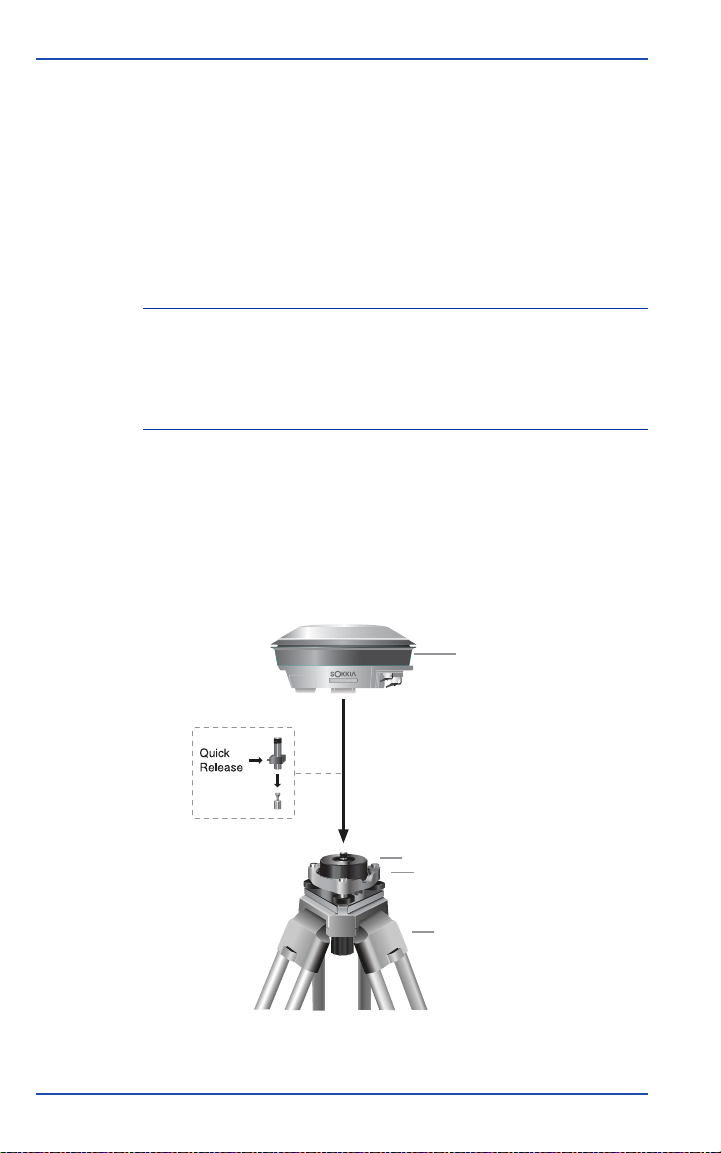
For static surveys, the GSR2700 IS is mounted on a tripod. The
system is operated using the power button, and is powered using
the internal batteries or an external battery. The setup might also
include a data collector for in-field configuration of the receiver.
GSR2700 IS
Receiver
Tribrach Adapter
Tribrach
Tripod
Figure 16: Typical Static Setup
40 GSR2700 IS Operations Manual
Page 52

System Setup Chapter 4
For a static survey, complete the following steps:
1. Ensure you have the appropriate POWERUP configuration
loaded onto the receiver (see Chapter 6, Collecting Data,
page 48).
2. Mount the GSR2700 IS on the tripod.
NOTE Position the receiver with the GPS antenna up and the
mounting socket down.
3. Turn on the receiver (see Chapter 5, Basic Operations,
page 42).
4. Check the memory gauge to verify that the receiver is
logging data (see Section 3.3.3, Memory gauge, page 29 for
more information).
5. (Optional) If you wish to see the current position and satellite
tracking status, you can connect a data collector to the
receiver using a Bluetooth connection, or serial
communication via the receiver’s COM1 (blue) port.
GSR2700 IS Operations Manual 41
Page 53

Chapter 5
This chapter describes how to power your GSR2700 IS and
describes basic receiver operations.
NOTE Before using the GSR2700 IS for the first time, ensure that you
have followed the setup instructions in Chapter 4, System
Setup, page 34.
Basic Operations
5.1 Turning the System On and Off
The GSR2700 IS has a power button that, when pushed, turns the
receiver on or off. For more information about the power button,
see Section 3.1, Power Button, page 20.
NOTE If you press the power button to turn off the GSR27000 IS while
it is logging data to the memory, it will save and close any open
files before turning off.
For information about power consumption while the receiver is
off, see Section 5.4, Power Consumption, page 44.
NOTE The GSR2700 IS does not turn on in response to COM port
activity.
5.2 Power Source
You may decide to power the GSR2700 IS using its internal
batteries, or you can choose to attach an external power source to
the system.
5.2.1 Internal batteries
The GSR2700 IS incorporates two internal battery packs. If the
internal batteries are completely discharged, the GSR2700 IS can
operate if an external power input is connected.
42 GSR2700 IS Operations Manual
Page 54

Basic Operations Chapter 5
For information about charging the internal batteries, see Section
5.6, Charging the Internal Batteries, page 46.
5.2.2 External power source
In addition to using the internal batteries, the GSR2700 IS can be
powered using an external battery according to the
recommendations in this section.
NOTE If you want to charge your receiver while driving a vehicle, use a
DC to AC inverter that meets the input specifications as detailed
in Appendix A, Technical Specifications, p age 55.
For the receiver to operate with an external power source, the
minimum operating voltage for the external power input cannot
be less than the minimum GSR2700 IS operating voltage. See
Appendix A, Technical Specifications, page 55 for detailed
information about the GSR2700 IS operating voltage.
CAUTION
If the external power input exceeds 18 VDC,
it may damage the receiver.
When an external power source is present, the GSR2700 IS uses it
before drawing on the internal batteries, provided that the power
from the external source is greater than that of the internal
batteries.
If the voltage delivered from the external power source is less
than the internal battery power, the internal batteries will be used
until they are drawn to the same level as the external source.
Once the internal and external batteries are discharged to the
same level, the receiver will draw equally from both sources.
When the receiver is on and connected to an external power
source that provides 14–18 VDC (including the AC Adapter), the
internal batteries will be charged while the receiver is operating.
GSR2700 IS Operations Manual 43
Page 55

Chapter 5 Basic Operations
5.3 Powering Peripheral Devices
The GSR2700 IS is capable of providing power to peripheral
devices, through its COM ports. The power output is
approximately the same as the input of the active battery.
NOTE Typically, the COM ports are not sent power . For example, since
most data collectors do not have a power pin, COM1 would not
usually provide power.
If the peripheral devices attached to the GSR2700 IS try to draw
too much power from the battery output, the receiver will limit
the available current to prevent damage to the receiver. Once the
excessive load is removed, normal operation of the system will
resume.
NOTE If a peripheral device (for example, a high -powered radio) was
the cause of the current drain, it will probably not function after
the system resumes normal operation.
If you use the Sokkia recommended data collector and radio, you
will not overload your system. This possibility only exists if you
attach peripherals that have not been approved for use with the
GSR2700 IS.
5.4 Power Consumption
The GSR2700 IS has been designed to minimize its power usage.
Power consumption is less than 5 W using the internal radio.
When the receiver is off, it still draws a small amount of power
from the batteries. If you store your GSR2700 IS for several
months without use, the batteries may become fully discharged.
If this happens, recharge the batteries to resume operation (see
Section 5.6, Charging the Internal Batteries, page 46).
44 GSR2700 IS Operations Manual
Page 56

Basic Operations Chapter 5
5.5 Insufficient Power
If both the internal batteries or the external power input voltage
are below minimum operating parameters (in other words, if the
GSR2700 IS experiences drained batteries or power failure), the
receiver will turn off and become inactive. If this happens, you
will not be able to turn the receiver back on until sufficient power
is restored.
In the event of a power failure, the GSR2700 IS power output is
disabled on both COM ports and the receiver will not resume
operations even if the power button is pressed.
To return to normal operation, charge the internal batteries or
connect a valid external power input to the receiver. When
sufficient power is restored, the COM ports will provide power
according to what the POWERUP configuration specifies and the
system will turn on if the power button is pressed. If there is no
POWERUP configuration, the COM ports will provide power as
they did before the power failure.
CAUTION
The GSR2700 IS may also become inactive
if the external power input is greater than
the power specified. See Section 1.7,
Finding More Information, page 8 for more
information.
NOTE The GSR2700 IS limits data loss from storage in the internal
memory to a maximum of 10 seconds in the case of power
supply failure.
GSR2700 IS Operations Manual 45
Page 57

Chapter 5 Basic Operations
5.6 Charging the Internal Batteries
When the batteries require charging, simply turn off the receiver
and connect the supplied AC Adapter.
NOTE Ensure the receiver is turned off when charging. Though it is
possible to charge the unit while operating, this is not
recommended.
CAUTION
The AC Adapter is designed specifically for
charging the GSR2700 IS. Do not use any
other charger with the GSR2700 IS.
Do not use the AC Adapter outdoors for
field operations with the GSR2700 IS.
While the receiver is charging, the top LED on the battery life
gauge blinks (see Section 3.3.1, Battery life gauge, page 27). The
LED stops blinking when charging is complete.
NOTE The internal batteries should be serviced by your local Sokkia
distributor. Do not attempt to service the batteries yourself—
doing so will void the product warranty.
5.7 Operation Overview
The following is a list of general operations when using the
GSR2700 IS receiver:
1. Apply power to the GSR2700 IS (that is, ensure its internal
batteries are charged or connect it to an external power
supply). Once the GSR2700 IS is connected to an appropriate
power supply, it is ready to use.
2. Turn the system on by pressing the power button. The
GSR2700 IS will acquire GPS satellites and then may
automatically start collecting data based on commands in the
46 GSR2700 IS Operations Manual
Page 58

Basic Operations Chapter 5
POWERUP configuration (see Section 6.3.1, About the
POWERUP configuration, page 49).
3. Connect a data collector to the receiver if you plan to use it to
configure the receiver or control the survey. A data collector
is not always necessary (for example, you are using the
receiver as an RTK base or in a static survey).
GSR2700 IS Operations Manual 47
Page 59

Chapter 6
The GSR2700 IS enables you to collect data in several ways and,
by using the POWERUP configuration, to define the type of
information stored during data collection.
Collecting Data
6.1 How Data is Stored
The most basic activity you will perform using your GSR2700 IS
is collecting raw data, which are recorded in the form of logs.
Each collection session (one uninterrupted period of time) is
stored in a single, unique data file in memory. Only one file is
open and recorded to at a time. This file can subsequently be
transferred to a PC for post-processing and adjustment using
Sokkia’s Spectrum Survey Suite software.
For information about how data files are named, see Section 6.4,
Data File Naming, page 53.
6.2 Data Collection Methods
The GSR2700 IS collects data with a handheld data controller, or
by logging to the internal memory.
6.2.1 Handheld data collection
You can use the GSR2700 IS receiver with a handheld data
controller loaded with the SDR+ software to configure and
initiate data collection.
NOTE SDR+ is capable of storing only RTK data on the data collector.
When you connect the data controller to the receiver (whether
using a wireless connection or a cable), a communication link is
established and the controller controls the behavior of the
receiver. When you turn on the GSR2700 IS, the preset
48 GSR2700 IS Operations Manual
Raw GPS data are always stored in the receiver’s internal
memory.
Page 60

Collecting Data Chapter 6
POWERUP configuration will run until the controller takes
control of the receiver.
Commands issued to the receiver through the controller will
supersede the POWERUP configuration resident on the receiver
(see Section 6.3.1, About the POWERUP configuration, page 49).
The receiver begins using the POWERUP configuration again
when you turn the receiver off and back on again.
Use the options in the SDR+ software to determine whether data
is stored on the receiver or on the controller.
6.2.2 Logging to the internal memory
Turn the receiver on by pressing the power button (see Section
3.1, Power Button, page 20). Once the GSR2700 IS has acquired
GPS satellites, it will automatically start collecting data based on
the POWERUP definitions (see Section 6.3.1, About the
POWERUP configuration, page 49).
NOTE For information abo ut downloading data from internal memory,
see Section 4.1, Setting Up at the Office, page 34.
6.3 Defining Data to be Collected
You can define what type of information should be collected
during a data collection session by using tools available in the
Sokkia Planning software to transfer a POWERUP configuration
to the receiver.
NOTE The GSR2700 IS does not support the use of schedules.
6.3.1 About the POWERUP configuration
A receiver’s POWERUP configuration is a group or set of data
that tells the receiver what type of information should be stored
during a data collection session.
GSR2700 IS Operations Manual 49
Page 61

Chapter 6 Collecting Data
The POWERUP configuration tells the receiver:
• What type of data to collect (for example, observations,
ephemeris, almanac).
• Where the data should be stored (for example, in internal
memory, or transmitted through COM1 or COM2).
• The interval at which data should be collected (for example,
every 10 seconds).
• The position (none, fixed, or averaged).
• The antenna height.
• The elevation mask.
• The site name and number.
• The COM port baud rates.
• The wireless communication power settings.
6.3.2 Default POWERUP configuration
The GSR2700 IS initially operates on a default POWERUP
configuration, which is always present on the receiver unless you
remove it using the Planning software.
There are several default POWERUP configurations available for
the GSR2700 IS. Your receiver is preset with one of five possible
POWERUP configurations. Table 14, POWERUP Configurations,
page 51 summarizes the factory setup for each.
NOTE To view the POWERUP configuration settings for your receiver,
use the Planning software. If you would like the factory default
POWERUP configuration setting changed to another of the five
choices, see your local Sokkia distributor.
50 GSR2700 IS Operations Manual
Page 62

Collecting Data Chapter 6
Table 14: POWERUP Configurations
RTCM
Static
15
Raw Observations
Log to file Yes Yes Yes Yes Yes
Recording interval
(seconds)
Minimum satellites
to store an epoch
Elevation mask
(degrees)
RTK Base Operation
Generate RTK
corrections
Average position
and fix time (secs)
Differential
correction format
Default base ID n/a 0 AAAA AAAA AAAA
Correction transmit
interval (secs)
15 10 10 10 15
33 3 3 3
55 5 5 5
NoYesYesYesYes
n/a 180 180 60 180
n/a RTCM
n/a 1 1 1 1
Base Std
10
18/19
RTCA
Base Std
10
RTCA RTCA RTCA
RTCA
Base
Rapid 10
RTCA
Base
Std 15
Base position
transmit interval
(secs)
Corrections to
internal radio if
present
Corrections to
external COM2
Peripheral Power
n/a10101010
n/a Yes Yes Yes Yes
n/a Yes Yes Yes Yes
GSR2700 IS Operations Manual 51
Page 63

Chapter 6 Collecting Data
Table 14: POWERUP Configurations (continued)
Send power to data
collector COM1
Send power to
external radio
COM2
RTCM
Static
15
No No No No No
No Yes Yes Yes
Base Std
10
RTCA
Base Std
10
RTCA
Base
Rapid 10
6.3.3 Transferring a POWERUP configuration
The Planning software provides several predefined POWERUP
configurations based on different data collection methods. You
can select one of the predefined POWERUP configurations and
transfer it to the receiver. You can also define your own
POWERUP configuration or edit one of the predefined
POWERUP configurations. See the Planning Reference Manual for
more information.
NOTE When you transfer a POWERUP configuration to the GSR2700
IS using Planning, it replaces the existing configuration on the
receiver. Only one POWERUP configuration can reside on the
receiver at one time.
RTCA
Base
Std 15
Yes
When you reset the receiver back to factory defaults, any
POWERUP configuration you have transferred to the receiver is
discarded, and the POWERUP configuration reverts to the
factory default settings (see Section 6.6, Resetting the Receiver,
page 54).
52 GSR2700 IS Operations Manual
Page 64
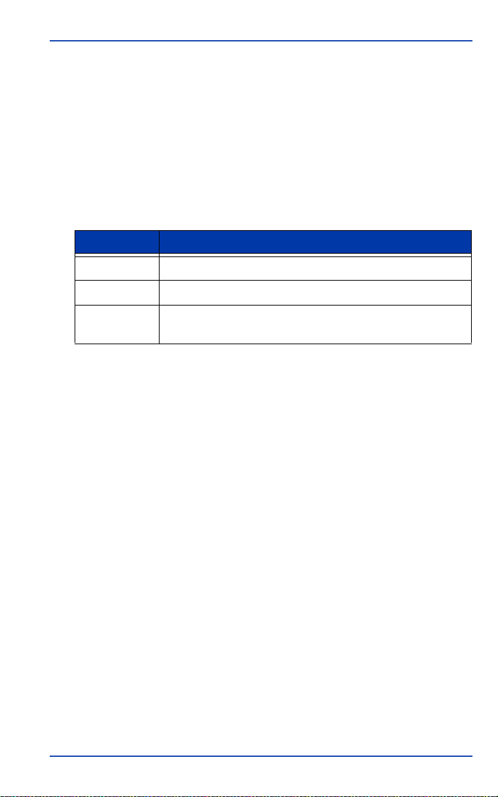
Collecting Data Chapter 6
6.4 Data File Naming
Auto-generated file names consist of an eight-character base
followed by a .PDC extension, as follows:
####$$$%.PDC
The eight characters are derived as shown in Table 15.
Table 15: Auto-Generated File Name Convention
Part of Name Description
#### Last 4 digits of the GSR2700 IS receiver’s serial number
$$$ UTC day of the year (001–366)
% Session ID assigned in sequence (0..9, A..Z) based on the
presence of files previously logged on a particular day.
For example, a GSR2700 IS might have a serial number such as
NZH05410087. If the day is January 25 (025 UTC day of the
year), and this is the 15th session created that day (session ID E),
the file name would be 0087025E.PDC.
In the unlikely event of a conflict between an auto-generated file
name and an existing file, the GSR2700 IS resolves the conflict by
creating a file name whose first character is a tilde (~), followed
by a 7-digit random number, and a .PDC extension (for example,
~9368412.PDC).
GSR2700 IS Operations Manual 53
Page 65
Chapter 6 Collecting Data
6.5 Data Storage Capacity
Table 16 indicates the approximate number of hours of data
logging to the internal memory for several recording intervals
based on the standard 64 MB internal memory.
Table 16: Hours of Storage with 64 MB Logging Capacity
Epoch
Rate
1 57 50 44 40 36 33 30
5 270 240 210 190 170 160 140
10 520 460 410 370 340 310 290
15 750 660 600 540 490 460 420
30 1350 1200 1090 990 910 860 800
60 2210 2010 1850 1710 1580 1520 1420
6 7 8 9 10 11 12
Average # of Satellites
6.6 Resetting the Receiver
Holding the power button down for the appropriate time period
(see Section 3.1, Power Button, page 20) restores the default
factory POWERUP configuration.
The receiver audibly indicates that a reset has occurred. For more
information, see Section 3.4, Audible Annunciator, page 31.
NOTE Data files on the receiver are not affected by a reset.
54 GSR2700 IS Operations Manual
Page 66

Technical
Appendix A
Table 17 summarizes the GSR2700 IS specifications.
NOTE Specifications are subject to change without notice.
Table 17: GSR2700 IS Technical Specifications
Specifications
Physical
Size (diameter x
height)
Weight Without internal radio: 1.6 kg (3.5 lbs)
Enclosure Description The enclosure is constructed of magnesium alloy
Operating Temperature -20°C to +65°C (-4°F to +149°F)
Storage Temperature -40°C to +85°C (-40°F to +185°F)
Humidity 100% condensing
Ruggedness • IP67. Complete protection against dust ingress.
a
Shock
22.5 cm x 10.5 cm (8.9 in x 4.1 in)
With internal radio: 1.8 kg (3.9 lbs)
(main body) and plastic (radome), closed with
mounting screws and encircled by a rubber bumper.
Environmental
Protected against immersion up to 1.0 m (3.3 ft).
• Buoyant
2.0 m pole drop (6.6 ft)
GSR2700 IS Operations Manual 55
Page 67

Appendix A
Table 17: GSR2700 IS Technical Specifications (continued)
Vibration (Rand om Prof ile )<from Radian IS manual; this section needs to be
confirmed or updated>
The GSR2700 IS can acquire and track satellites while undergoing vibration
levels as shown below. It assumes that C/No > 45 db-Hz and that the
GSR2700 IS is in high-dynamics mode. Assuming appropriate mounting, the
GSR2700 IS conforms to random vibration templates for RTCA/DO-160D,
Section 8 (Curve C template), MIL-STD-202F, Test Condition I (Letter A
nominal template), and ASAE EP455, Section 5.15.1 nominal template.
Frequency < 10 Hz, 10 Hz, 40 Hz, 1000 Hz, 2000 Hz, > 2000
Hz
Magnitude (g2/Hz) + 80 dB/decade, 0.00125, 0.02, 0.02, 0.005, -80 dB/
decade
Power Requirements
Power Input • External: +9 VDC to +18 VDC
• Internal: +10.8 VDC
Consumption <5 W using internal radio
Port 1 x external power port
Peripheral Power Output (COM1 and COM2)
Voltage ≅ supplied voltage
Current 1 A
Power Management
Once the internal batteries are completely discharged, the GSR2700 IS
becomes inactive. Normal operations are resumed when you charge the
internal batteries or when you connect an external power source to the system.
For further details, see Section 5.2.2, External power source, page 43.
56 GSR2700 IS Operations Manual
Page 68

Appendix A
Table 17: GSR2700 IS Technical Specifications (continued)
Performance (Subject to GPS System Characteristics)
Frequency 1575.42 MHz (L1) & 1227.60 MHz (L2)
Channels 12 x L1 and 12 x L2 with full code and carrier
Time to First Fix (TTFF)
• Cold start: 50 s (typical)
• Warm start: 40 s (typical)
• Hot start: 30 s (typical)
Signal Reacquisition • 0.5 sec L1 (typical)
• 0.5 sec L2 (typical)
b
c
d
Computed Data
20 solutions per second (maximum)
Update Rate
Measured Data Update
20 data records per second (maximum)
Rate
Position Accuracy
Static
e
:
• 3.0 mm + 0.5 ppm (horizontal)
• 10.0 mm + 1 ppm (vertical)
Rapid Static
e
:
• 5.0 mm + 1 ppm (horizontal)
• 10.0 mm + 1 ppm (vertical)
Kinematic, Stop-and-Go
e
:
• 10.0 mm + 1 ppm (horizontal)
• 20.0 mm + 1 ppm (vertical)
f
RTK
:
• 10.0 mm + 1 ppm (horizontal)
• 20.0 mm + 1 ppm (vertical)
Differential (DGPS) WAAS/EGNOS: 0.8 m CEP
Latency 0.02 sec (typical)
Stand-Alone Position 1.5 m CEP (4.9 ft)
Time Accuracy
(relative)
g
20 ns (SA off)
Height Limit Up to 18,288 m (60,000 feet), in accordance with
export licensing
RTK Initialization
h
3–10 sec (typical) based on satellite constellation
and baseline length
GSR2700 IS Operations Manual 57
Page 69

Appendix A
Table 17: GSR2700 IS Technical Specifications (continued)
Memory
Memory • Internal: 64 MB standard
• Optional: up to 2 GB
Memory Life 500 hours at 10-second interval (6 satellites)
Internal Batteries
Capacity 2200 mAh
Voltage 10.8 VDC
Chemistry Li-Ion
Operating Time 20°C • Rover: 10 hours with internal batteries and
internal UHF radio
• Static: 14 hours with internal batteries and no
internal radio usage
Charge Time max. 5 hours
Charging Voltage 14 VDC to 18 VDC, 65 W
Radio Link
UHF • compatible with SATEL Satelline-3AS
• 380 to 470 MHz
• Transmit and Receive (Tx/Rx)
• 12.5 kHz channel spacing
• Power consumption (typical; at 1 second
transmits and in receive mode): <information not
yet available>
• RF impedance: 50 ohms
• RF connector type: TNC female
GSM/GPRS • Nokia 12 GSM
Communication ports 2 x RS232, 1 x USB, 1 x Bluetooth, 1 x internal radio
Serial electrical format EIA/TIA-232-E
• Frequencies: 850/1800 MHz or 900/1900 MHz
band
• Power consumption (typical): <information not yet
available>
• RF connector type: TNC female
Input/Output Data Interface
58 GSR2700 IS Operations Manual
Page 70

Appendix A
Table 17: GSR2700 IS Technical Specifications (continued)
Serial EIA/TIA-232-E
Baud Rate
• COM 1: 4800, 9600 (default), 19200, 38400,
57600, 115200, 230400, 460800, 921600
• COM2: 4800, 9600 (default), 19200, 38400,
57600, 115200, 230400
Serial signals
TX, RX, RTS, CTS
supported
Wireless interface Bluetooth v1.1
USB USB version v1.1
Input/Output Strobes
PPS Output
i
A one-pulse-per-second time synchronization
output. This is a normally high, active low pulse (1
ms ± 50 ns) where the falling edge is the reference.
Mark Input
j
An input mark (negative pulse > 55 ns), time tags
output log data to the time of the falling edge of the
mark input pulse.
The electrical specifications of the strobe signals are as follows:
Output • Voltage: Standard TTL levels
• Sink Current: 64 mA
• Source Current: 15 mA
Input • Voltage: Standard TTL levels
• Current: ≤ 5 mA
Classifications
FCC and CE Complies with the radiated and conducted emission
limits for a Class B digital device, for both CISPR
and Part 15 of the FCC Rules. For full details, see
GSR2700 IS FCC and CE Notice, page ii.
a. Shock specifications based on receiver without cables attached.
b. Typical value. No almanac or epheme r is and no approximate position or time.
c. Typical value. Almanac saved and approximate position and time entered. No recent
ephemeris.
d. Typical value. Almanac and recent ephemeris saved and approximate position and
time entered.
e. Accuracy depends on number of satellites used, obstructions, satellite geometry
(DOP), occupation time, multipath effects, atmospheric conditions, baseline length,
survey procedures, and data quality . 95% confidence level. Baselin e not exceeding 10
km (except for Static survey type).
f. 1 sigma.
g. Time accuracy does not include biases due to RF or antenna delay.
GSR2700 IS Operations Manual 59
Page 71

Appendix A
h. Based on unobstructed observing conditions, 7 satellites, and a baselin e l ength of
less than 5.0 km.
i. See your local Sokkia distributor for more information.
j. See your local Sokkia distributor for more information.
60 GSR2700 IS Operations Manual
Page 72

Glossary
A
Ambiguity—The unknown integer number of cycles of the
reconstructed carrier phase. The carrier phase ambiguity is inherent
in an unbroken set of measurements from a single satellite pass at a
single receiver. Also known as integer ambiguity and integer bias.
Antenna—The antenna is the component of a GPS system that
collects the analog signal from the GPS satellite and sends this signal
to the GPS receiver for processing.
B
Base station—In differential positioning, a base station is the end of
the baseline that is assumed known and its position fixed. It is the
GPS receiver which is acting as the stationary reference. It has a
known position and transmits messages for the rover receiver, which
uses the information to calculate its position. Sometimes referred to
as a reference station.
Bluetooth—Wireless personal area network (PAN) standard that
enables data connections between electronic devices such as desktop
computers, wireless phones, electronic organizers, and printers in the
2.4 GHz range at 240 Kbps within a 30-foot range. Bluetooth depends
on mobile devices being equipped with a chip for sending and
receiving information.
C
C/A Code—See Coarse/Acquisition (C/A) Code.
Carrier phase—The phase of either the L1 or L2 carrier of a GPS
signal, measured by a receiver while locked onto the signal (also
known as integrated Doppler).
Circular Error Probable (CEP)—The radius of a circle, centered at
your true location, that contains 50% of the individual position
measurements made.
GSR2700 IS Operations Manual 61
Page 73

Glossary
Coarse/Acquisition (C/A) Code—The Coarse/Acquisition (or
Clear/Acquisition) code modulated onto the GPS L1 signal.
D
DOP—See Dilution of Precision (DOP).
DGPS—See Differential GPS (DGPS).
Datum—A model of the Earth used for geodetic calculations.
Differential GPS (DGPS)—A technique to improve GPS accuracy. It
primarily uses pseudorange errors at a known location to improve
the measurements made by other GPS receivers within the same
general geographic area.
Dilution of Precision (DOP)—The geometry of the visible satellites
is an important factor in achieving high quality results. The geometry
changes with time due to the relative motion of the satellites. An
accuracy measure for the geometry is the DOP factor.
E
Elevation mask angle—An adjustable feature in GPS receivers that
specifies a satellite must be at least a specified number of degrees
above the horizon before the receiver uses the signals from that
satellite. Satellites at low elevation angles (five degrees or less) have
lower signal strengths and are prone to loss of lock and multipath.
Ellipsoid—A smooth mathematical surface that represents the
Earth’s shape and very closely approximates the geoid. It is used as a
reference surface for geodetic surveys.
Ellipsoidal height—The height above a defined ellipsoid,
approximating the surface of the Earth.
Ephemeris—A set of satellite orbit parameters used by a GPS
receiver to calculate precise GPS satellite positions and velocities. The
ephemeris is used in the determination of the position solution and is
updated periodically. Available as “broadcast ephemeris” or as postprocessed “precise ephemeris”.
62 GSR2700 IS Operations Manual
Page 74

Glossary
G
GPRS—See General Packet Radio Service (GPRS).
GPS—See Global Positioning System (GPS).
GSM—See Global System for Mobile Communications (GSM).
Global Positioning System (GPS)—A space-based radio
positioning system which provides suitably equipped users with
accurate position, velocity, and time data.
Global System for Mobile Communications (GSM)—A digital
cellular phone technology based on TDMA. First introduced in 1991,
the GSM standard has been deployed at three different frequency
bands: 900 MHz, 1800 MHz, and 1900 MHz. GSM uses narrowband
TDMA which allows eight simultaneous calls on the same radio
frequency.
General Packet Radio Service (GPRS)—Technology that allows
mobile phones to be used for sending and receiving data over an
Internet Protocol (IP) based network.
GPS Time—The time system upon which GPS is based. GPS time is
an atomic time system and is related to International Atomic Time in
the following manner: International Atomic Time (IAT) = GPS +
19.000 sec. The IAT and Universal Time Coordinated (UTC) are
closely related. The difference is that UTC contains leap seconds to
adjust for changes in the earth’s rotation. See Universal Time
Coordinated (UTC).
I
Integer ambiguity/bias—See Ambiguity.
Integrated Doppler—See Carrier phase.
GSR2700 IS Operations Manual 63
Page 75

Glossary
Ionosphere—The layers of ionized air in the atmosphere extending
from 70 kilometers to 700 kilometers and higher. Depending on
frequency, the ionosphere can either block radio signals completely or
change the propagation speed. GPS signals penetrate the ionosphere
but are delayed. This delay induces error in the GPS measurements
that can result in poor survey results. Most GPS receivers/processing
software model the ionosphere to minimize its affects. Also, the
effects of ionosphere can be nearly eliminated by using dual
frequency receivers which can calculate the delay due to ionosphere.
L
L1—The 1575.42 MHz GPS carrier frequency, which contains the
course acquisition (C/A) code, as well as encrypted P-code and
navigation messages used by commercial GPS receivers.
L2—A secondary GPS carrier (at 1227.60 MHz) that contains only the
encrypted P-code.
L-Band—The range of radio frequencies that includes the GPS L1
and L2 carrier frequencies and the OmniSTAR satellite signals.
M
Mask angle—See Elevation mask angle.
Multipath—The reception of a satellite signal both along a direct path
and along one or more reflected paths. Reflecting surfaces near the
GPS antenna cause this type of reflected signal. The resulting signal
results in an incorrect measurement and thus errors in position
estimates. In other words, these are errors caused by the interaction of
the GPS satellite signal and reflections.
N
NMEA—National Marine Electronics Association, an organization
that created an industry standard ASCII log types used by many
receivers.
64 GSR2700 IS Operations Manual
Page 76

Glossary
O
Occupation time—A period of continuous data of sufficient quality
for post-processing.
P
P-Code (Precise or Protected)—The protected or precise code used
on both LI and L2 GPS frequencies.
Phase Center—The phase center of a GPS antenna is the physical
location on the antenna where the raw GPS signals are observed. This
is the physical location where the computed position will be
determined.
Pseudorange—The calculated range from the GPS receiver to the
satellite. It is determined by taking the difference between the
measured satellite transmit time and the receiver time of
measurement, and multiplying it by the speed of light.
R
RMS—See Root-Mean-Square (RMS).
Radio Technical Commission for Maritime Services (RTCM)—
Radio Technical Commission for Maritime Services. An organization
that developed and defined the SC-104 message format for
differential positioning.
Raw data—GPS data which has not been processed or differentially
corrected.
Real-time Kinematic (RTK)—A type of differential positioning
based on observations of carrier phase.
Reference station—See Base station.
Rover receiver—The GPS receiver that moves from site to site
during an RTK survey. The receiver does not know its position and
needs to receive measurements from a base station to calculate
differential GPS positions at each point.
Root-Mean-Square (RMS)—A statistical measure of the scatter of
computed positions about a “best fit” position solution.
GSR2700 IS Operations Manual 65
Page 77

Glossary
S
SLA—Sealed Lead Acid battery.
SIM card—Subscriber Identify Module card. A small printed circuit
board that must be inserted in any GSM-based mobile phone when
signing on as a subscriber. It contains subscriber details, security
information, and memory for a personal directory of numbers. The
SIM card also stores data that identifies the caller to the network
service provider.
T
TNC—A threaded version of the Bayonet Neill-Concelman (BNC)
connector.
Time-To-First-Fix (TTFF)—The actual time required by a GPS
receiver to achieve a single point position solution. This specification
varies with the operating state of the receiver, the length of time since
the last position fix, the location of the last fix, and the specific
receiver design.
U
Universal Serial Bus (USB)—An external peripheral interface
standard for communication that supports data transfer rates up to
480 Mbps.
Universal Time Coordinated (UTC)—The time as maintained by the
U.S. Naval Observatory. Due to variations in the Earth's rotation, the
UTC is sometimes adjusted by an integer second. The accumulation
of these adjustments compared to GPS time, which runs
continuously, caused an 13 second offset between GPS time and UTC
at the start of 1999. However, after accounting for leap seconds and
using adjustments contained in the navigation message, GPS time
can be related to UTC to within 20 nanoseconds or better.
66 GSR2700 IS Operations Manual
Page 78

Glossary
W
WGS84—The World Geodetic System 1984 is an coordinate system
designed to fit the shape of the Earth as much as possible. It is often
used as a reference on a worldwide basis, while other coordinate
systems are used locally to provide a better fit to the Earth in a local
region.
GSR2700 IS Operations Manual 67
Page 79

Page 80

Index
A
anchor point, 16
antennas
GPS, 16
internal radio, 13, 17
wireless communication, 12
audible annunciator, 31–33
B
base components, 5
base setup
RTK, 37–40
static, 40
batteries
battery life gauge, 27
external, 14–15, 43
internal, 15, 42–43, 46
low condition, 32
power output, 14, 44
Bluetooth. See wireless communica-
tion
button, power. See power button
C
cables, 14–15
cautions for usage, 6
charging internal batteries, 27, 43,
46
collecting data, 48–54
color coding of ports, 14
COM ports, 14, 24
communication
ports, 14, 24–25
status indicators, 24–25
wireless. See wireless communi-
cation
components, 3–5, 10–18
configurations. See POWERUP con-
figuration
consumption, power, 44
corrections, ionospheric, 2
covers for ports, 12
current, maximum, 6
customer support, 9
D
data
collecting, 48–54
defining for collection, 49–52
file naming, 53
loss of, 45
storage, 48, 54
transferring, 34–35
See also files
default POWERUP
configuration, 50
deleting files, 22
display panel
features, 20–33
icons, 7
overview, 19–20
documentation
conventions, 8
related, 8
downloading data, 34–35
E
enclosure, overview of, 10
erasing the memory, 22
error conditions, 23
external battery, 14–15, 43
F
factory reset, 22, 54
features summary, 2
GSR2700 IS Operations Manual 69
Page 81

Index
field setup, 35
files
deleting, 22
naming conventions, 53
See also data
formats, logs, 3
G
gauges
about
battery life, 27
memory, 29
occupation timer, 30
satellite tracking, 28
GSM/GPRS radio, 17
H
handheld data collection, 48
height measurement point, 16
I
icons, 7
indicators, status. See status indica-
tors
insufficient power, 45
interruptions, logging, 42
ionospheric corrections, 2
L
LEDs. See gauges; status indicators
log formats, 3
logging
interruptions, 42
memory capacity, 54
rates, 3
to internal memory, 49
M
maximum current, 6
memory, internal
about, 16
erasing, 22
full or low conditions, 32–33
gauge, 29
logging to, 49
modes of operation, 2
mounting socket, 11
N
naming conventions, files, 53
O
occupation timer gauge, 30
office setup, 34–35
operation
display panel, 19–33
modes, 2
overview, 46
optional components, 5
output power, 14, 44
overview, 1
P
peripheral devices, powering, 14, 44
phase center offset, 11
ports
antenna, 13, 17
color coding, 14
communication, 14, 24–25
covers for, 12
icons, 7
overview, 12–13
power, 14
status indicators, 24
post-processing data, 34–35
power
consumption, 44
input, 14–15, 43
insufficient, 45
output, 14, 44
70 GSR2700 IS Operations Manual
Page 82

Index
power button
about, 20, 42
functions, 21–22
power port, 14
POWERUP configuration
default, 50–52
overview, 49
transferring, 52
R
radio, internal
about, 17
antenna, 13, 17
status indicators, 26
rates, logging, 3
receiver health indicator, 23
resetting the receiver, 22, 54
rover components, 4
rover setup, 35–37
S
satellite tracking gauge, 28
schedules, 49
setup
about, 34
office, 34–35
RTK base, 37–40
RTK rover, 35–37
static base, 40
shutdown, 21
SIM card, 17
socket, mounting, 11
sounds. See audible annunciator
specifications, 55–60
startup sequence, 21
static setup, 40
status indicators, 22
storage of data, 48, 54
support, technical, 9
system components, 3–5, 10–18
system setup. See setup
T
tape measure anchor point, 16
technical specifications, 55–60
technical support, 9
transferring data, 34–35
transferring POWERUP
configuration, 52
troubleshooting, 23
U
UHF radio, 17
usage cautions, 6
USB communication, 14
V
voice messages. See audible annun-
ciator
W
warning conditions, 23
wireless communication
about, 1, 17
antenna, 11
status indicators, 25
GSR2700 IS Operations Manual 71
Page 83

Page 84

<CE declaration document not yet available>
Page 85

Page 86

SOKKIA has been delivering superior products, sales and support around the world
since 1920. You can find an authorized SOKKIA representative in nearly every
region of the globe. For customer service, we recommend that you contact your local
SOKKIA distributor. If you need assistance locating a distributor in your area,
please contact the appropriate SOKKIA worldwide office listed below.
AFRICA, MIDDLE EAST, SOUTH EAST ASIA
SOKKIA Singapore Pte. Ltd.
Singapore
CENTRAL & SOUTH AMERICA
POINT, Inc.
Olathe, Kansas, U.S.A.
Ph:+1 800-764-6848
+1 913-928-2787
Fax: +1 913-492-8233
E-mail: [email protected]
SOKKIA Latin America
Miami, Florida, U.S.A.
CHINA
SOKKIA Co. Ltd. Shanghai Representative Office
Shanghai, People’s Republic of China
EUROPE
SOKKIA B.V.
Almere, The Netherlands
JAPAN
SOKKIA Co. Ltd. International Dept.
Atsugi, Kanagawa, Japan
Ph: +81-46-248-7984
Fax: +81-46-247-1731
Web: www.sokkia.com.jp
Page 87

OCEANIA (AUSTRALIA/NEW ZEALAND)
POINT Oceania
Newcastle, New South Wales, Australia
SOKKIA Pty. Ltd.
Rydalmere, New South Wales, Australia
NORTH AMERICA
POINT, Inc.
Olathe, Kansas, U.S.A.
Ph: +1 800-764-6848
+1 913-928-2787
Fax: +1 913-492-8233
E-mail: [email protected]
SOKKIA Corporation U.S.A.
Olathe, Kansas, U.S.A.
Ph: +1 800-4-SOKKIA
+1 913-492-4900
SOKKIA Corporation Canada
Mississauga, Ontario, Canada
SOUTH KOREA
SOKKIA Korea Co. Ltd.
Seoul, Republic of Korea
TAI WA N
Meridware Co., Ltd.
Taichung, Taiwan
 Loading...