

Pogo 30 Owner's Manual

OWNER’S MANUAL
POGO STRUCTURES
Z.A. De Kerbénoen
29120 Combrit
Tél: 02.98.51.94.73

1
Index:
Introduction
p.2
Hull Identification
Number
p.2
1.
Main Characteristic
p.3
2.
Certification
p.3
3. Security
p.4
4.
Engine
p.5
5.
Swinging Keel
p.6
6.
Rudder system
p.10
7.
Draining
p.10
8. Fire Fighting
p.11
9.
Electricity
p.12
10.
Fresh Water
p.13
11.
Black Waters
p.13
12.
Installed
Equipment
p.14
13.
Maintenance
p.15
14
. Navigation Guide
p.18
15.
Warranty Terms
p.19
16.
Environmental Impact
p.19
Annexes
p.20
2
Introduction
This guide was written to help you to use your boat with pleasure and safety. It contains all details
concerning your Pogo, its equipment and all information about the way to use and take care of it.
Read it carefully before sailing.
If this is your first boat, or is a boat you are not familiar with, we recommend that you practice
controlling the boat in light conditions and sheltered waters. Learn how the boat behaves at different
speeds. Be sure having enough experience before taking responsibility as skipper. Your retailer, the
national federation or your local boating organisation will be pleased to find a suitable course. This
manual does not exempt you to comply with the local and international laws in force.
KEEP THIS MANUAL IN A SAFE PLACE AND MAKE SURE IT GETS TRANSFERED TO THE NEW OWNER IN
CASE OF RESELLING.
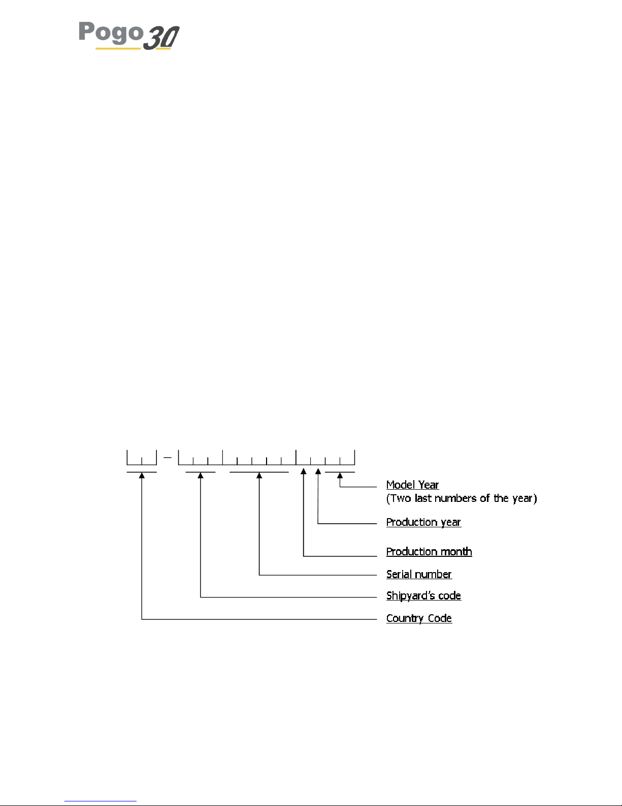
Hull Identification Number (n°HIN)
You’ll find it engraved on the starboard corner of the transom of the boat.
How to read it:
3
1. Main Characteristics
2. Certification
Your boat was built in France and has been certified in accordance with the applicable parts of the
directive for pleasure craft 94/25/EC of the European Parliament.
The different equipment of your ship such as the rudder system, the fuel tank, hoses... also certified
and thus corresponds to the current European standards.
This boat has been design for category A with a limited number of passengers of 4 in accordance with
ISO 12217-2. This category is considered as being designed for use in waves.
Users of this boat are informed that:
• All passengers must be trained
• The boat must not be loaded more than recommended by the shipyard.
• There must be enough water clearance to sail
• Stability is reduced if you add some load in the ups.
• Water bilge must be minimised
• In bad weather conditions, all hatches, chests and doors must be closed to avoid water in-
take.
• Stability can be reduced when the boat is towing or hangs important load with her davit or
boom.
• Breaking wave can represent a big danger to stability
Length: 9.14m (30 feets)
Beam: 3.70m
Displacement: 2800kg
Draft: Swinging keel: 1.05m/2.50m
Fixed keel: 1.95m
Air draft: 14.7m
Square-top main: 30m²
Classic main: 26m²
Solent: 26m²
Spinnaker: 75–85 m²
Carbon or Aluminium mast

4
Description of the design categories:
A. - A category A pleasure boat is designed regarded as for winds who can exceeding 8 force
(Beaufort scale) and make waves who exceed significant height of 4m. But excluding the great
conditions such as storms, violent storms, tornadoes and extremes sea conditions or huge waves.
B. - A category B pleasure boat is designed regarded as for winds may reach 8 Beaufort included and
waves which can have a height of 4 meters included.
C. - A boat of design category C is designed regarded as for winds may reach 6 Beaufort included and
waves which can have a height of 2 meters included.
D. - A boat design category D is designed regarded as for winds may reach 4 Beaufort included and
waves which can have a height of 0,3 meters included. With, occasional, waves of maximum height
of 0.5 meters.
The boats of each design category shall be designed and constructed to resist to the settings
concerning the stability, buoyancy, and other essential technical requirements, contained in the
official document (decree n° 2016-763 / 09-06-2016) and to have good manoeuvrability
characteristics.
3. Security
For security purpose, the use of a harness is highly recommended. To do so, some folding padeyes
(2400kg resistance) are disposed in the cockpit as well as two lifelines running on the deck on port
and starboard. We remind you that life-lines are mandatory.
Do not forget that wearing a lifejacket can save your life.
Regularly check the integrity of your lifelines and that of the guard lines and all attachment parts.
Particular care must be taken regarding the rope attachment of the guard lines to the balconies. It
must be able to support 1500 kg or above (for example, 8 turns of 200kg lines).
DANGER

5
4. Engine
Engine Type:
Standard Engine for Pogo 30 is the D1-13 from Volvo Penta Sail-drive. Optionally, it can be fitted with
D1-20 or D1-30. The propeller is a folding two blades from Volvo Penta as well.
Use and maintenance of the engine :
Please refer to the Volvo Penta manual called “instruction book”. A complete reading of the manual
before service is recommended to prevent damage and know the wear parts of the engine.
Engine cooling inlet seacock:
It is very important to check the cooling seacock is open before starting the engine. It is located on
the sail-drive base, on portside. You can access it by the port cabin hatch.
When the engine is on, check the water circulation of the cooling system. Some water should come
out of the exhaust.
At the engine start, it is recommended to put some power for a few seconds in order to properly
initiate the cooling system.
Check lists
It is very important to correctly take care of your engine. Follow the maintenance schedule and check
the engine oil and coolant level.
Check the sacrificial anode carefully. The first one’s erosion will happen quickly. Check them
regularly.
Stay up to the property of the service module and check regularly that there are no outflows (fuel,
water).
Information
If you need more information about your engine and its maintenance, please contact your Volvo
Penta dealer for assistance.
Gasoil tank:
The installed diesel tank has a capacity of 60L. It is equipped with a fuel supply cut down valve. This
valve must always be accessible
AVERTISSEMENT
AVERTISSEMENT

6
5. Swinging keel
Th is chapter doe s not con cern the owner s of a fixed keel P ogo 3 0
The Keel must be in the lower position when sailing
Operation:
Given the electrical power needed to use the keel ram, it is necessary to start the engine tu use the
Hydraulic set of the keel (only for electrical swinging keel systems.
Once the engine is on, the keel movements are piloted by the two buttons located on the starboard
panel of the central.
You may stop the movement at any time using the third red button.
Access to the Hydraulic system:
To access the hydraulic system, unscrew the 4 top aft screws of the central table. Then slide the
entire aft part of the table aft wards.
Maintenance:
A regular checkup of the oil level is recommended to detect eventual leaks. The system oil drain must
be done every two years.
The oil leveling must be done keel in lower position (or ram in shortest position). NEVER EXCEED
MAX MARK, there are risk of tank explosion.
The Oil used is ISO-L-HV type, grade 46 (mineral hydraulic oil, 46 centistokes viscosity).
When getting the boat out of water, perform a visual check of the underwater parts of the keel
system: the rotation axis.
DANGER
DANGER
7
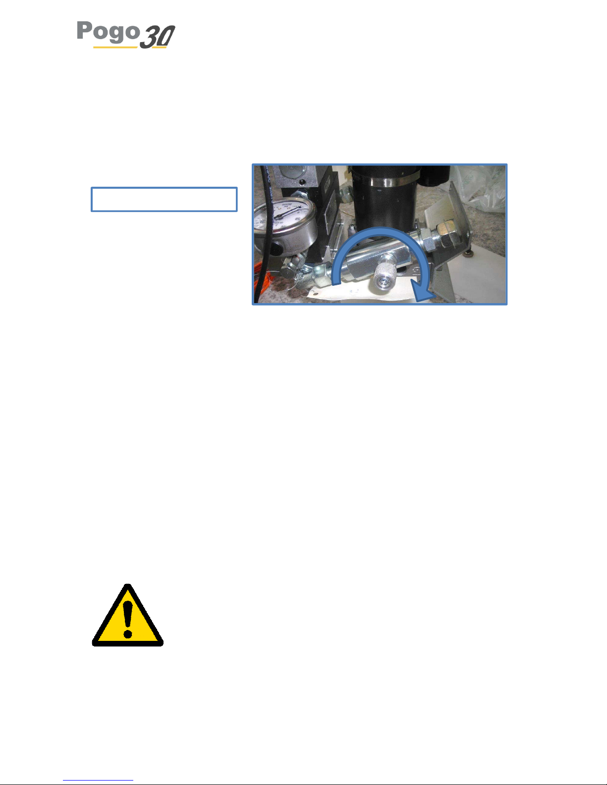
Tuning of the hydraulic system’s brake
The keel system is tuned at the shipyard.
However, it might be necessary to have a look at the brake if the oil viscosity changes with
temperature. Fits and starts while lowering the keel represents such a need.
When should you use this setting:
The keel comes down by fits and starts
The keel doesn’t reach its bottom stop
How to adjust:
If the keel come down by fits and starts, you have to tighten the brake (turn clockwise). Be
careful, adjust with fineness, turn by eighth of a turn (maximum half a turn, usually eighth of
a turn is enough).
The hydraulic brake is a turnable button that must be turned clockwise. The tuning must be
made in with precaution and fineness. Usually, ⅛ of a turn is enough. Do not hesitate to
contact the shipyard.
If the keel doesn’t reach its bottom stop, it’s necessary to loosen the brake. To verify if the
keel is in bottom stop, look if the axis of jack is in front of the porthole.
If the keel comes up by fits and starts, you shouldn’t touch the brake
’s
setting. It’s certainly necessary to grease the rotation system of the keel.
Every settings must be made in cold conditions.
Hydraulic brake srew
8
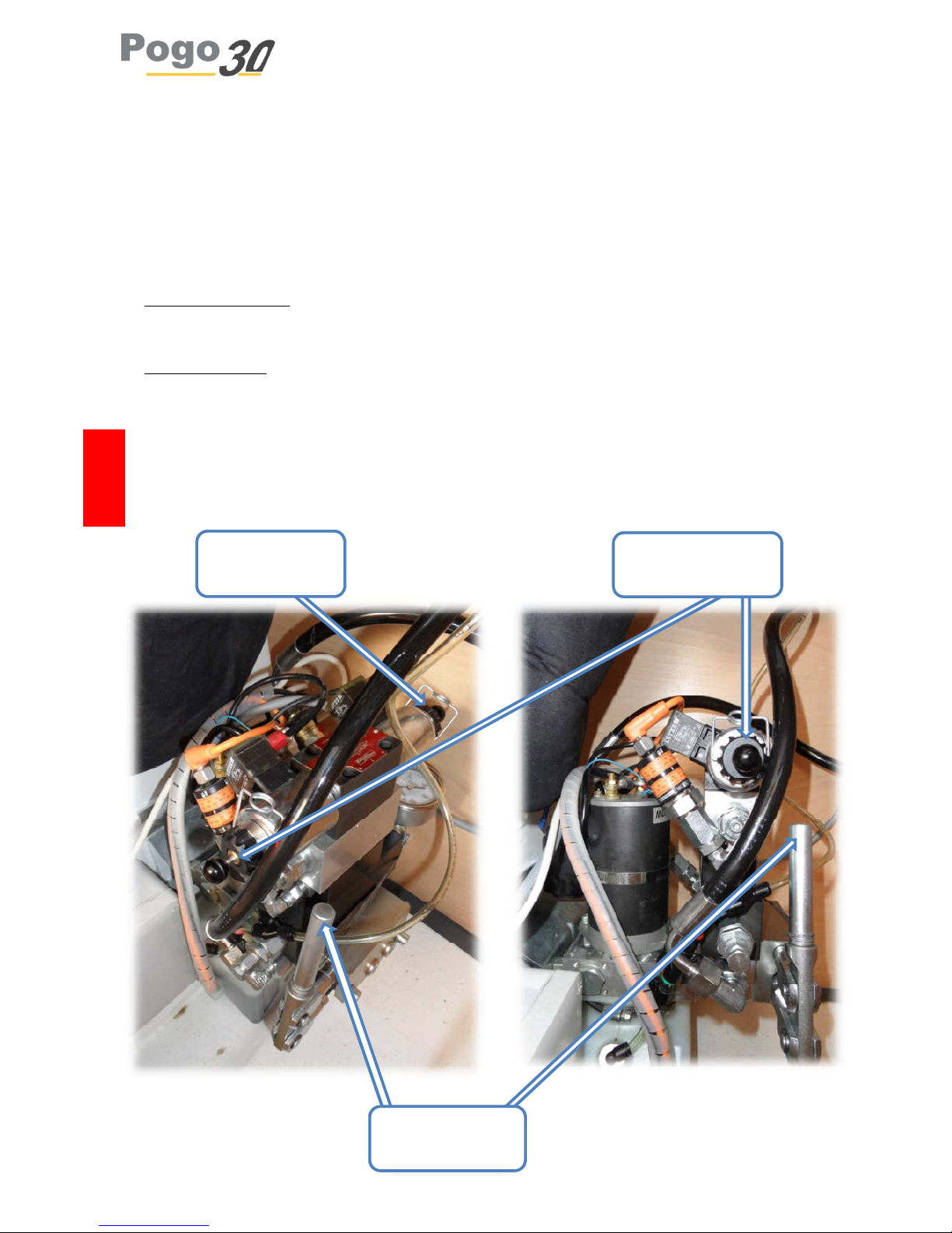
Manual manoeuvre of the electrical keel system :
In case of an energy breakdown, you can manually activate the keel to put it in top or low position.
To do so :
Open the central table in order to have access to the hydraulic central.
Take the arm tube
Put it in the manual pump (see pict. below)
To get the keel down: clip the spring on the starboard spherical button in order to maintain it firmly
pushed, and then pump (see pict. below)
To get the keel up: clip the spring on the portside spherical button in order to maintain it firmly
pushed, and then pump (see pict. below)
Only push one button at the time. In normal conditions, both buttons must be free of the springs.
DANGER
Port button
: keel
uplowering the keel
Starbo
ard button:
lowering the keel
Support for
manual arm
9
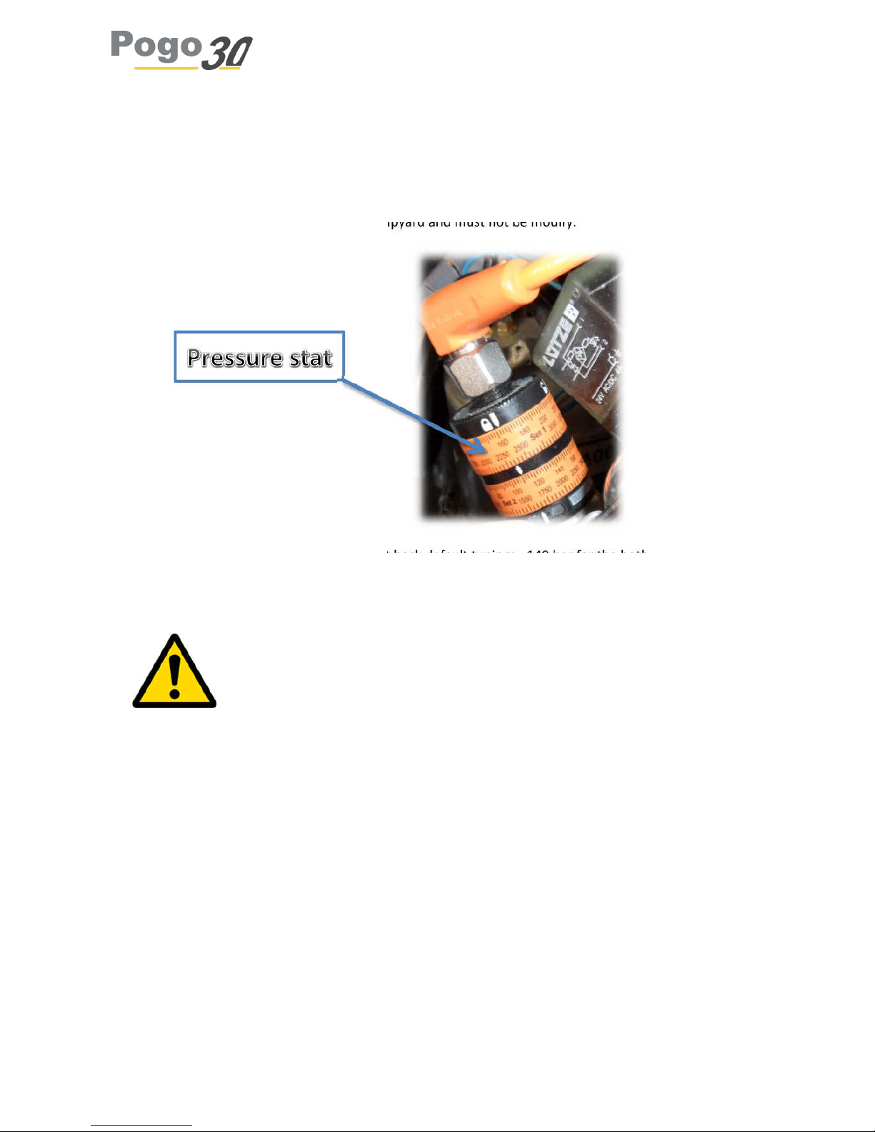
Keel’s hydraulic setting
Pressure stat tunings
Pressure stat tunings are realized in the shipyard and must not be modify.
If however it’s inadvertently disturbed, put back default tunings : 140 bar for the both orange
adjusting rings.
To turn orange adjusting rings, think of unbolting the black adjusting ring.

10
6. Rudder system
Rudder parallelism setting:
You can adjust the parallelism of your rudders. It is possible because the screw threads are inverted
on port and starboard. After having removed the blocking screw, at each extremity, simply turn the
link tube one way or the other to adjust its total length. Always keep 20mm of thread in the tube.
Firmly screw the blocking screws back.
Maintenance:
The bearings do not need any particular attention. A regular fresh-water clean-up is however
advised. To grease the bearing, use marine quality grease.
Removing a rudder:
To unmount a rudder: disconnect the link tube, unscrew all the bolts along the rudder-shaft, make
sure the rudder is supported and only then, remove the top cube.
7. Draining
The Pogo 30 comes with a bilge pump system composed of a manual pump in the cockpit and an
electrical pump in the aft part of the technical zone.
They are both linked to the same circuit. The inlet is situated at the end of the transportable tube,
rolled in the technical area and the water come out in the cockpit. You can access any part of the
boat using this tube. A filter is installed right before the pump.
It is recommended to regularly check the pump and also that the filter is not blocked.
The total capacity of the system cannot sustain the boat sinking or with excessive waterway.
It is recommended to regularly check the water tightness of the system and that of the seacocks and
loch/speedo instruments to avoid any leak. Always keep emergency plugs close to the seacocks.
To dry the bilges, we recommend you remove the carpet slip floor regularly.
DANGER

11
8. Fire-fighting
The Pogo 30 is equipped, optionally, with a 2kg powder class C extinguisher (minimal capacity
5A/34B) situated at the will of the owner.
A discharge opening for the engine compartment is situated close to the circuit breakers. It allows
the extinguishing material and foam to be poured directly on the engine.
Please check the validity of the equipment and its availability on-board.
Heating:
The Pogo 30 is equipped, optionally, with a heating system Eberpacher Airtronic D2. Please read
carefully the instructions and recommendations of the manual.
The shipyard is keen to insist on two points:
The engine is very silent and is situated if the technical area. It is important not to let it in
contact with the exhaust of the engine, nor with any sail because of the temperature it
quickly raises to.
Once the heating is turned off, it is very important to keep the current on for the time it cools
down.
DANGER
ATTENTION

12
9. Electricity
The standard electrical system of the Pogo 30 consists of the followings:
One 55Ah battery dedicated to the engine start. It is installed in the engine compartment, in
front of the engine and is accessible by the companionway opening. Circuit breakers are
located on starboard locker.
One 100Ah service battery installed in the same place
Electrical boards:
The main electrical board on the chart table
The secondary one is located on the aft longitudinal stiffener, on starboard.
The electrical installation has been made for the installation on-board and is not planned for
supplementary equipment.
Regularly check the fixation of the batteries.
Never work with current on.
Do not modify the electrical scheme made by the shipyard. The modifications must be made by a
professional marine electrician.
Do not change the breaking capacity of the circuit breakers.
Do not install any equipment with electrical intensity higher than that of the previously installed.
Do not let the boat without visual check when the electrical system is on.
The electrical scheme is available at the end of this manual
ATTENTION

13
10. Fresh Water
The standard fresh-water installation on board the Pogo 30 is composed of the followings:
Canvas water bag Nauta 135L
Water pressure unit with its filter
General tap.
Sink with tap and evacuation system, including seacock.
Some precautions must be taken using the water canvas bag:
“NAUTA® flexible tanks used for drinking water will operate more satisfactory if the following
procedures are observed. Before putting in use for the first time, partly fill the tank with warm water
(50°c) and a 1% solution of mild detergent. After a few minutes, rinse with clear water and fill it again
with water treated with chlorine tablets (follow package instructions for a 5% concentration). Empty
after 2 hours and carefully and thoroughly rinse with clear water. These cleaning operations should
be performed with the system fully installed so that all the piping undergoes the same treatment.
When the tank will not be used for a long period (winter layup…), keep it partly filled with water and
10% of chlorine solution. Because it is not possible to completely evacuate the tank, this procedure
best prevents the development of microorganisms which could coat the inside and contribute to a bad
taste in water.
Before returning the tank to service, follow the same procedure as used with a new tank. Even if using
your tank constantly, this cleaning operation is recommended at 6 months interval. Do not forget that
the pipes also contribute to the water's taste and should be involved in the regular cleaning process.”
Recommendations NAUTA - ORC®
When filling your NAUTA water tank, we recommend that it is not filled beyond its total capacity. In
practice, the filling hose should not be full of water and the input connector does not must touch the
access door panel.
11. Black Waters
The pogo 30 is optionally equipped with a black water tank. It is then located on top of the toilets. It
has a 60L capacity.
If you want to use it, close the valve situated in front of the toilets. Its opening will allow the
emptying of the tank.
To drain it, use the deck access.
ATTENTION

14
12. Installed equipment
For the use of equipment installed on-board, please refer to their manual.
In case of problem with one of them, please contact the reseller of the brand concerned.
Setting and initialization of the equipment:
Some equipment such as automatic pilot or log speedo requires initialization before use. Therefore,
It is important to refer to the manual for these devices to configure optimally.
Valves and plumbing:
All the valves must be closed after use. Installed seacocks:
Loch/speedo: situated in front of the keel structure.
Kitchen: under the kitchen furniture, you will find the sink exhaust seacock. You can access
the valve by the aft side of the furniture.
Toilets: it requires two valves. The inlet is situated in front of the gas tank. The outlet is in
front if the toilets
Exhaust: The exhaust of the engine is made over the waterline, in front of the aft
compartment. The valve is accessible by the starboard locker.
It is important that adapted rescue fittings are always available to block the seacocks in case of
waterway. Regularly check the plumbing systems.
Electrical circuit:
It is recommended to cut the circuit breakers after navigation.
Gas:
The Pogo 30 is equipped with a burner and gas tank Campingaz type. It may also be equipped with a
double burner gaz. In that case, the gas bottle is located in an aft locker, only accessible from the
cockpit.
Before each use, the tap must be open and then closed. If the must does not have surveillance for
several days, unplug the gas bottle.
While using the gas burner, it is recommended to open the hatch above it.
ATTENTION
DANGER
15
13. Maintenance
General care
For good ventilation when the boat is moored it is advised to let the deck hatches (locked by the
centre handle), the 2 cockpit portholes (rear cabin and storage room) and the companion way panel
open
For your comfort and the health of your boat it is important to dry correctly and regularly the interior
of your boat.
To guarantee optimal ageing of your boat, do not leave stagnant waters in funds under the floor
mats. If necessary, after drying, leave the carpets, on edge, of drying time.
Before the winter storage please rinse the interior with fresh water to put off the salt. During the
storage it is advised to install a humidity absorber.
Cleaning
To clean the interior you can use household cleaning agents. For the deck it is better to use a specific
agent or a coachwork cleaning agent.
Do not throw into the sea waste water with oil or/and fuel oil.
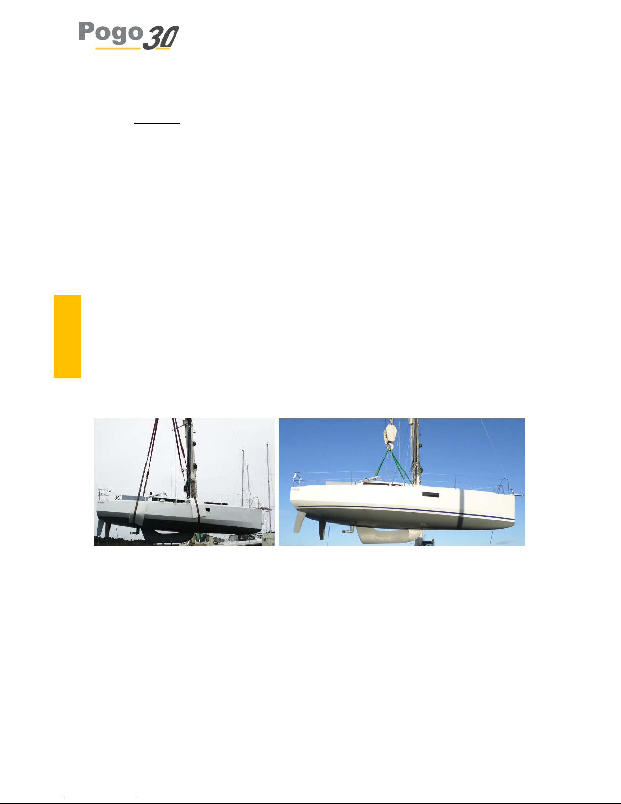
Lifting
Traditional lifting: With the option « quick lifting system » :
All precautions are to be taken during the lifting of your boat. Ensure clearance of the mast from
crane hook.
With the option « quick lifting system » :
The Pogo 30 lifting pack is delivered with four padeyes fixed on deck, security ropes and shackles.
The aft padeyes are located just aft of the companionway, on the cockpit floor. The forward ones are
on the guardrails (do not us the cleat). Is the keel is in high position, put the shackles at the end of
the two forward padeyes to fix the two ropes and fix the aft ropes to the aft padeyes using a lark’s
head knot.
ATTENTION
 Loading...