

PNI Corporation V6000 User guide
OPERATION MANUAL
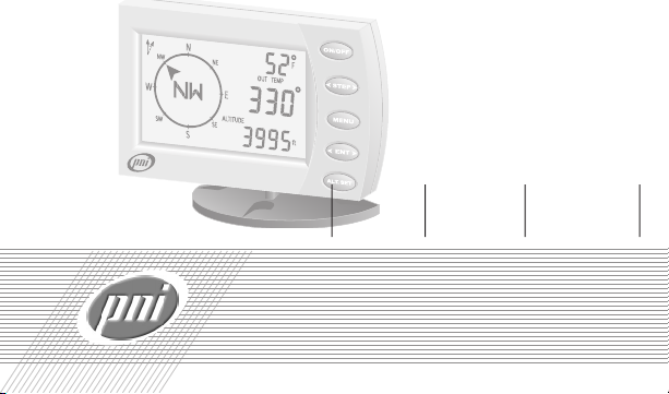
V6000 DIGITALVEHICLECOMPASS

Making Ordinary Products Extraordinary

CONGRATULATIONS!
You have purchased one of the most
sophisticated compasses available for use
in a vehicle. The PNI V6000 is a valuable
tool for your vehicle, utilizing technology to
make a digital compass easy and informative
to use, while still incorporating patented
magnetic sensor technology to give you
accurate compass headings. PNI’s magnetic
sensor technology electronically measures
your vehicle’s magnetic eld and calibrates
for inaccuracies mathematically with its
built-in microprocessor. The result is
unequaled compass performance in a vehicle
environment.
Features
• Uses patented magnetic sensor technology, same as the built-in compasses in
GM, Ford, and Chrysler vehicles.
• Altimeter displays the current altitude in
feet or meters.
• Barometer displays barometric pressure
and up/down trends to determine
weather patterns.
• Weather forecast displays a three-level
weather forecast of SUN, CLOUD, or
RAIN, based on the last 24 hours of
barometric pressure information.
1

FEATURES
• Indicates inside temperature, outside
temperature and ICE alert in either
Fahrenheit or Celsius.
• Declination adjustment allows the unit to
be set to either true or magnetic north.
• Bearing point stores one compass heading
at a time in memory to stay on desired
course.
• Automatic power shut-off occurs when
no magnetic eld changes have been
sensed for approximately 10 minutes.
• Programmable backlight auto shut-off
feature.
• Photo sensor feature turns the backlight
on or off depending on the amount of
ambient light.
• Distortion indicator alerts you when
magnetic interference from outside
sources, such as steel from a bridge or
overpass, is affecting compass accuracy.
• Holographic LCD improves brightness
and contrast while removing glare.
• One-year warranty.
2

CONVENTIONS USED IN THIS MANUAL
1. The LCD icons are written in all capital
letters with quotes around them.
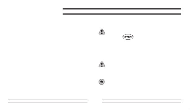
2. Buttons used in procedures are presented
as button icons.
3. Procedures are organized so that the
action to perform follows the step
number, and result of that action is
indented.
4. “Press” means press and release a button
in less than 2 seconds.
5. “Hold” means press and hold the button
for at least 2 seconds, or until a display
appears.
6. Indicates a warning or important
information
7. Indicates optional equipment available at additional cost.
8. The 3 horizontal lines of display on the
right side will be referred to as line 1
through 3 starting at the top.
3

CONTENTS
Display and Buttons . . . . . . . . . . . . . . . . . . 5
Installation . . . . . . . . . . . . . . . . . . . . . . . . . 8
Step 1: Installing the battery . . . . . . . . . . . 8
Step 2: Installing the 12-volt adapter . . . . 9
Step 3: Installing the external
temperature sensor . . . . . . . . . . . 10
Step 4: Mounting the unit . . . . . . . . . . . 12
Programming and Operation . . . . . . . . . 16
Calibration mode . . . . . . . . . . . . . . . . . . 16
Declination mode . . . . . . . . . . . . . . . . . . 18
Backlight mode . . . . . . . . . . . . . . . . . . . . 20
Photo sensor feature . . . . . . . . . . . . . . . .22
Bearing mode . . . . . . . . . . . . . . . . . . . . . 23
Barometer mode . . . . . . . . . . . . . . . . . . . 25
Weather forecast display . . . . . . . . . . . . . 26
Temperature mode . . . . . . . . . . . . . . . . . 27
ICE alert feature . . . . . . . . . . . . . . . . . . . 27
Altitude mode . . . . . . . . . . . . . . . . . . . . . 28
Alt.Set mode . . . . . . . . . . . . . . . . . . . . . . 29
Optional Accessories . . . . . . . . . . . . . . . . 30
Declination Angle Map . . . . . . . . . . . . . . 31
General Specications . . . . . . . . . . . . . . . 32
Frequently Asked Questions . . . . . . . . . . 35
Service and Replacement . . . . . . . . . . . . . 37
Warranty . . . . . . . . . . . . . . . . . . . . . . . . . . 38
4
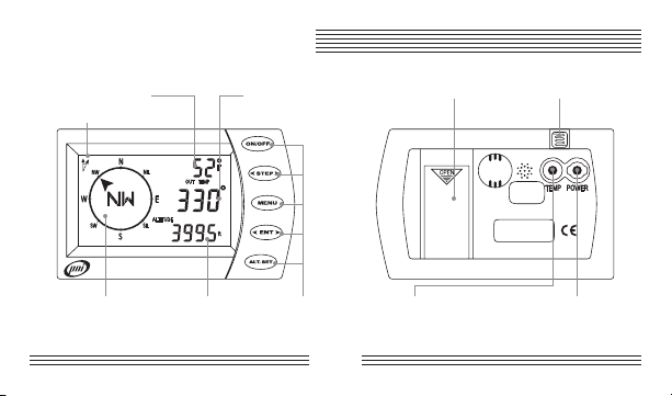
DISPLAY AND BUTTONS
Temperature and Numeric Heading
Bearing Point Readout Readout
Declination Icon
Compass Rose Altitude, Barometer Buttons
and Weather Forecast Readout
FRONT
Battery Photo Sensor
Compartment
Temperature 12-Volt Power
Sensor Jack AdapterJack
BACK
5

DISPLAY AND BUTTONS
The PNI V6000 displays direction of travel in
three different formats: (1) cardinal points,
(2) numeric digits (325°, 330°, etc.), and
(3) compass rose. The eight cardinal points
of a compass (N, NE, E, etc.) give you the
general direction. The numeric digits show
your exact direction to the nearest 1°. The
compass rose arrow points in the direction
you are heading relative to north.
The slow ashing of the degree symbol in
line 2 indicates when magnetic interference
is compromising compass accuracy or when
a battery has been installed.
Buttons
ON/OFF button
Press or any other button to turn
compass on and hold to turn compass
off. Once on, pressing toggles the
backlight on or off.
STEP button
Press in normal display mode to toggle
between displaying “IN TEMP” (inside temperature), “OUT TEMP“ (outside temperature), and “BEARING” (bearing point). Press
in programming mode to advance
through the values to select.
6

DISPLAY AND BUTTONS
MENU button
Press to advance through programming
menu options “CALIb” (calibration), “dECL”
(declination), “LIGHt” (backlight), “bEAr”
(bearing point), “bAro” (barometer), “tEMP”
(temperature) and “ALt” (altimeter) and to
exit a programming menu.
ENT button
Press in normal display mode to toggle
between barometric pressure, altitude, and
weather forecast. Press in programming
mode to store a displayed value.
ALT.SET button
Press as a quick reset for altitude. It
resets the altitude from the currently displayed
altitude to the stored altitude.
7

INSTALLATION
Step 1: Installing the battery
The PNI V6000 uses a CR123 Lithium type
battery, installed according to the diagram
on the inside of the battery compartment.
Push the battery straight down into the
compartment, not at an angle. To remove,
open the battery compartment and tap the
back of the unit against the palm of your
hand and the battery will come out.
Once the battery is inserted, the unit will
go through a quality test. If the display
becomes stuck, remove the battery, wait for
approximately one minute, and then reinsert
the battery.
If the battery is the only power source,
whenever the battery is changed or removed,
the PNI V6000 must be calibrated and all
previous feature settings must be reset. With
the 12-volt adapter or the hardwire kit
installed, the battery may be removed or
changed without affecting any settings.
The PNI V6000 has an auto shut-off feature.
When no magnetic eld change has been
detected for approximately 10 minutes, the
compass automatically switches off and saves
all settings.
8

HEADER
INSTALLATION
Step 2: Installing the 12-volt adapter
Installing the 12-volt adapter is optional, but
recommended. Insert the small end into the
jack marked “POWER,” located on the back
of the compass, and plug the large end into
your cigarette lighter receptacle.
The photo sensor feature of the PNI
V6000 is operational only when the
12-volt adapter is plugged in or the
optional hardwire kit is installed.
Since cars do not always have constant
power supplied to the lighter receptacle,
you must keep a battery in the PNI
V6000 at all times to allow the unit to
keep memory settings.
A 15-foot hardwire kit is available at
additional cost. See Optional
Accessories.
9

HEADER
INSTALLATION
Step 3: Installing the external
temperature sensor
The PNI V6000 has a built-in internal
temperature sensor designed to measure
the temperature inside the vehicle at the
windshield (“IN TEMP”).
The PNI V6000 also includes a wire
temperature tether designed to measure
the temperature outside the vehicle (“OUT
TEMP”). The sensor end of the tether
must be mounted outside of the passenger
compartment, away from engine heat or
direct sunlight, in a place where there is
natural airow to the sensor, such as in the
grill area or door jamb. It is best to adhere the
sensor on a surface that is least conductive
to heat -- such as on a rubber or plastic
surface as opposed to the steel body of the
vehicle. The temperature from this sensor is
displayed as “OUT TEMP.”
Every vehicle is different, making it impossible
to list all possible sensor locations. Use
your best judgment to select the site for
the temperature sensor and experiment with
various locations, if necessary.
10
HEADER
INSTALLATION
To install the external temperature sensor:
1. Insert the connector end of the tether
into the jack marked “TEMP,” located on
the back of the compass.
2. Adhere the sensor end of the tether
outside of the passenger compartment.
Make sure the mounting surface is free of
oil and dirt.
3. (Optional, but suggested) Use the
included retainer clips to secure the
temperature tether to the windshield or
dashboard.
If the temperature sensor is not plugged
in and is toggled to “outside
temperature” display, the message
“PLUG IN TEMP CABLE” will scroll in
the upper right corner three times, then
will display “_ _ _ °F.”
Do not leave the PNI V6000 in a parked
vehicle that is likely to be exposed to
extremely hot or cold temperatures.
A 30-foot temperature sensor is
available at additional cost. See
11

HEADER
INSTALLATION
Optional Accessories.
Step 4: Mounting the unit
• Choose a place on the windshield that
will not obstruct the driver’s view and is
within reach so the buttons are easy to
push. Make sure the windshield surface
is clean. Once installed, the face of the
compass must be pointing toward the
rear of the vehicle.
• The unit can be tilted up or down a
maximum of 20° from road level. If tilted
more than ±20°, the heading information
after calibration may not be accurate.
The selected angle from road level must
stay xed after calibration for the heading
to remain accurate (see illustration on
page 13).
• The accuracy of the PNI V6000 will be
diminished by a strong magnetic eld,
such as that found in proximity to an
audio speaker. It is recommended that
the unit be mounted 5 or more inches
away from stereo speakers.
12
 Loading...