

Page 1

User Manual
PNI CommBoard
Page 2

Table of Contents
1 COPYRIGHT & WARRANTY INFORMATION ................................................. 1
2 INTRODUCTION ......................................................................................... 2
3 SPECIFICATIONS ......................................................................................... 3
3.1 Mechanical Drawing ............................................................................. 4
4 SET-UP ....................................................................................................... 5
4.1 Communication Setup .......................................................................... 5
4.2 Hardware Setup .................................................................................... 6
5 SPI OPERATION .......................................................................................... 9
5.1 SPI Commands ...................................................................................... 9
5.2 SPI Code Examples .............................................................................. 14
5.2.1 RM3100 Eval Board Cycle Count Register Read ........................ 14
5.2.2 More RM3100 Eval Board Code Examples ................................ 16
5.2.3 RM3000-f Eval Board Code Examples ........................................ 16
5.2.4 V2Xe Code Examples .................................................................. 16
6 I2C OPERATION ........................................................................................ 18
6.1 I2C Commands ..................................................................................... 19
List of Tables
Table 2-1: Applicable PNI Products & Interfaces 2
Table 3-1: I/O Characteristics 3
Table 3-2: Environmental Requirements 3
Table 3-3: Mechanical Characteristics 3
Table 4-1: UART Configuration 5
Table 5-1: SPI Command Summary Table 9
Table 5-2: SPI Syntax Character Definitions 10
Table 5-3: Handshake Signal Status 13
Table 6-1: I2C Command Summary Table 18
List of Figures
Figure 3-1: CommBoard Top View 4
Figure 4-1: CommBoard Configuration Block Diagram 6
Figure 4-2: CommBoard Signal and Power Connections 6
Figure 4-3: CommBoard Jumper Configurations 7
Figure 5-1: SPI Activity for RM3100 Cycle Count Register Read 14
PNI Sensor Corporation DOC#1018122 r02
PNI CommBoard User Manual Page i
Page 3

1 Copyright & Warranty Information
© Copyright PNI Sensor Corporation 2012
All Rights Reserved. Reproduction, adaptation, or translation without prior written permission is prohibited, except
as allowed under copyright laws.
Revised May 2013. For most recent version visit our website at www.pnicorp.com
PNI Sensor Corporation
2331 Circadian Way
Santa Rosa, CA 95407, USA
Tel: (707) 566-2260
Fax: (707) 566-2261
Warranty and Limitation of Liability. PNI Sensor Corporation ("PNI") manufactures its TCM products (“Products”)
from parts and components that are new or equivalent to new in performance. PNI warrants that each Product to be
delivered hereunder, if properly used, will, for one year following the date of shipment unless a different warranty
time period for such Product is specified: (i) in PNI‟s Price List in effect at time of order acceptance; or (ii) on PNI‟s
web site (www.pnicorp.com) at time of order acceptance, be free from defects in material and workmanship and will
operate in accordance with PNI‟s published specifications and documentation for the Product in effect at time of
order. PNI will make no changes to the specifications or manufacturing processes that affect form, fit, or function of
the Product without written notice to the OEM, however, PNI may at any time, without such notice, make minor
changes to specifications or manufacturing processes that do not affect the form, fit, or function of the Product. This
warranty will be void if the Products‟ serial number, or other identification marks have been defaced, damaged, or
removed. This warranty does not cover wear and tear due to normal use, or damage to the Product as the result of
improper usage, neglect of care, alteration, accident, or unauthorized repair.
THE ABOVE WARRANTY IS IN LIEU OF ANY OTHER WARRANTY, WHETHER EXPRESS, IMPLIED, OR
STATUTORY, INCLUDING, BUT NOT LIMITED TO, ANY WARRANTY OF MERCHANTABILITY,
FITNESS FOR ANY PARTICULAR PURPOSE, OR ANY WARRANTY OTHERWISE ARISING OUT OF ANY
PROPOSAL, SPECIFICATION, OR SAMPLE. PNI NEITHER ASSUMES NOR AUTHORIZES ANY PERSON
TO ASSUME FOR IT ANY OTHER LIABILITY.
If any Product furnished hereunder fails to conform to the above warranty, OEM‟s sole and exclusive remedy and
PNI‟s sole and exclusive liability will be, at PNI‟s option, to repair, replace, or credit OEM‟s account with an
amount equal to the price paid for any such Product which fails during the applicable warranty period provided that
(i) OEM promptly notifies PNI in writing that such Product is defective and furnishes an explanation of the
deficiency; (ii) such Product is returned to PNI‟s service facility at OEM‟s risk and expense; and (iii) PNI is satisfied
that claimed deficiencies exist and were not caused by accident, misuse, neglect, alteration, repair, improper
installation, or improper testing. If a Product is defective, transportation charges for the return of the Product to
OEM within the United States and Canada will be paid by PNI. For all other locations, the warranty excludes all
costs of shipping, customs clearance, and other related charges. PNI will have a reasonable time to make repairs or
to replace the Product or to credit OEM‟s account. PNI warrants any such repaired or replacement Product to be
free from defects in material and workmanship on the same terms as the Product originally purchased.
Except for the breach of warranty remedies set forth herein, or for personal injury, PNI shall have no liability for any
indirect or speculative damages (including, but not limited to, consequential, incidental, punitive and special
damages) relating to the use of or inability to use this Product, whether arising out of contract, negligence, tort, or
under any warranty theory, or for infringement of any other party‟s intellectual property rights, irrespective of
whether PNI had advance notice of the possibility of any such damages, including, but not limited to, loss of use,
revenue or profit. In no event shall PNI‟s total liability for all claims regarding a Product exceed the price paid for
the Product. PNI neither assumes nor authorizes any person to assume for it any other liabilities.
Some states and provinces do not allow limitations on how long an implied warranty lasts or the exclusion or
limitation of incidental or consequential damages, so the above limitations or exclusions may not apply to you. This
warranty gives you specific legal rights and you may have other rights that vary by state or province.
PNI Sensor Corporation DOC#1018122 r02
PNI CommBoard User Manual Page 1
Page 4
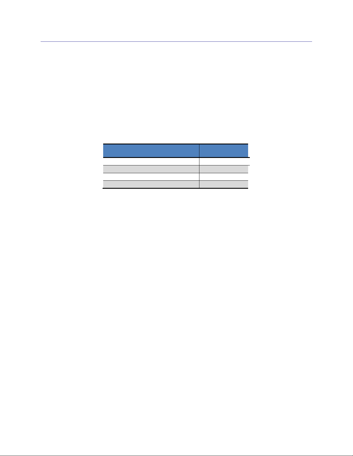
PNI Product
Interface
RM3100 Evaluation Board
I2C or SPI
RM3000-f Evaluation Board
SPI
V2Xe
SPI
SpacePoint Scout
I2C or UART
2 Introduction
Thank you for purchasing PNI Sensor Corporation‟s CommBoard, pn 13466. The CommBoard
is a printed circuit assembly (PCA) that acts as an easy-to-use interface between a PC and certain
PNI products. The CommBoard is a UART to SPI or I2C bridge which receives UART
commands from the user‟s computer via a virtual communication port running over a USB line.
The applicable PNI products and their interface types are listed below.
Table 2-1: Applicable PNI Products & Interfaces
PNI Sensor Corporation DOC#1018122 r02
PNI CommBoard User Manual Page 2
Page 5

Parameter
Value
Host
Interface
Communication Interface
Virtual UART on USB
Protocol
ASCII
Communication Rate
115200 baud
Device
Interface
Communication Interface
I2C or SPI
SPI Interface
Lines
SCLK, MISO, MOSI, SSN
CPOL
Selectable (default = 0)
CPHA
Selectable (default = 0)
Clock Speed
50 kHz, 100 kHz (default), 1 MHz
I2C Clock Speed
Selectable 32 kHz – 1 MHz
(100 kHz default)
Parameter
Value
Operating Temperature
-40C to +85C
Storage Temperature
-40C to +85C
Parameter
Value
Dimensions (l x w x h)
50.8 x 63.5 x 15.5 mm
(2.0” x 2.5” x 0.6”)
Weight
17 gm
Connector
Mini-USB
3 Specifications
Table 3-1: I/O Characteristics
Table 3-2: Environmental Requirements
Table 3-3: Mechanical Characteristics
PNI Sensor Corporation DOC#1018122 r02
PNI CommBoard User Manual Page 3
Page 6

3.1 Mechanical Drawing
Figure 3-1: CommBoard Top View
PNI Sensor Corporation DOC#1018122 r02
PNI CommBoard User Manual Page 4
Page 7

Parameter
Value
Baud Rate
115200
Number of Data Bits
8
Start Bits
1
Stop Bits
1
Parity
none
4 Set-Up
4.1 Communication Setup
The CommBoard‟s physical interface is USB, but it runs a virtual UART over the USB line.
As such, it is necessary to implement a virtual communication port (VCP) on the user‟s
computer. The CommBoard uses FTDI‟s FT232R USB-to-RS232 IC, and the driver for this
IC should be installed on your computer. This driver can be found on FTDI‟s website at:
http://www.ftdichip.com/Drivers/VCP.htm.
After installing the VCP driver and plugging in your PNI device, connect the CommBoard to
your computer using a USB-to-mini-USB cable. The USB line provides power to the
CommBoard and the device-under-test. The UART should be configured as shown below.
Table 4-1: UART Configuration
Figure 4-1 shows how a computer connects to a PNI device mounted on the CommBoard.
On the computer side, the user will send commands using an ASCII terminal program such
as HyperTerminal or Realterm. Alternatively, Matlab or a similar application that outputs
ASCII can be used. These all will use a Virtual Comm Port to place their UART commands
on the USB line of the computer. On the PNI CommBoard, the UART commands either are
translated into SPI commands or I
2
C commands using the CommBoard‟s CPU, or sent
directly to the PNI device. Whether the UART commands are translated into SPI or I2C, or
fed directly into the PNI device, is established by the jumpers, discussed in Section 4.1.
PNI Sensor Corporation DOC#1018122 r02
PNI CommBoard User Manual Page 5
Page 8

Figure 4-1: CommBoard Configuration Block Diagram
4.2 Hardware Setup
Figure 4-2 indicates where power connections can be made to the CommBoard, and also
where the signal lines are connected. For most users, the power and signal lines will be
supplied via the mini-USB jack. Next configure the jumpers on the CommBoard to match
your device, as illustrated in Figure 4-3.
Figure 4-2: CommBoard Signal and Power Connections
PNI Sensor Corporation DOC#1018122 r02
PNI CommBoard User Manual Page 6
Page 9

Figure 4-3: CommBoard Jumper Configurations
PNI Sensor Corporation DOC#1018122 r02
PNI CommBoard User Manual Page 7
Page 10

Plug your PNI device into the CommBoard. Pin 1 of the device should plug into pin 1 on the
CommBoard. For the SpacePoint Scout and V2Xe, this means the arrow printed on the
device will point towards the CommBoard‟s mini-USB connector, while for the RM3100 and
RM3000-f Evaluation Boards the arrow will point away from the mini-USB connector.
Finally connect the CommBoard to your computer using a USB-to-mini-USB cable. The red
and blue LEDs on the CommBoard should light up. Press the Reset button (SW1) on the
CommBoard to ensure the computer is correctly interpreting your device‟s communication
protocol
PNI Sensor Corporation DOC#1018122 r02
PNI CommBoard User Manual Page 8
Page 11

ASCII
Char.
Command
Syntax
Response
W, w
SPI Write
W{NIML}#(delimiter){{NIML}#(delimiter)…}{<CR>}
R, r
SPI Read
R{#}{S}(NIML){{#}{S}(NIML)…}<CR>
#{(delimiter)#...}{<CR>}
,
<SP>
<TAB>
<CR>
Delimiter
Delimiters. Used to separate characters or data
in a string. Sending a delimiter also changes the
default delimiter used in the return data string
sent to host.
X, x
Hex/ Decimal
X = Hex mode (default), x= Decimal mode
~
Hold for
DRDY
~1 = Hold until DRDY HIGH,
~0 = Hold until DRDY LOW
Y, y
Hold Always
Y
Q
Quit Hold
Q (Capital „Q‟ only)
F
Flush UART
Receive
Buffer
F (Capital „F‟ only)
?
Handshake
Status
?
Num2str (Uint8) or
dec2hex(Uint8). More
verbose in terminal
mode
!
Pulse CLEAR
pin
!
$
SSN Control
$1 = Set SSN HIGH, $0=Set SSN LOW
.
Pause 2 ms
.
V, v
CPHA Setting
“V” sets CPHA=1, “v” sets CPHA=0
O, o
CPOL Setting
“O” sets CPOL=1, “o” sets CPOL=0
Z, z
Clock Rate
“Z” = 1 MHz, “z” = 50 kHz, default = 100 kHz
T, t
Terminal
Mode
“T” turns on verbose terminal mode. “t” turns off
terminal mode.
For “T”: Sign-on text
including mode and
version number
5 SPI Operation
The RM3100 Evaluation Board, RM3000-f Evaluation Board and V2Xe incorporate a SPI
interface. For the RM3100 an I2C interface is also available, as discussed in Section 6. This
section reviews how to use the CommBoard to communicate with these SPI devices via a
computer using a terminal emulation program. Note the CommBoard not only converts UART
to SPI, but it also allows for control and monitoring of the SSN, CLEAR, and DRDY lines.
5.1 SPI Commands
A summary of the commands relevant for working with SPI devices is given below.
Table 5-1: SPI Command Summary Table
PNI Sensor Corporation DOC#1018122 r02
PNI CommBoard User Manual Page 9
Page 12

Character
Definition
( )
Required parameter inside parentheses
{ }
Optional parameter inside brackets
#
Number (data). Can include minus (-).
S, s
Treat incoming word as a signed value
N, n
Int8 value follows or is requested
I, i
Int16 value follows or is requested
M, m
Int24 value follows or is requested
L, l
Int32 value follows or is requested
Table 5-2 defines the characters used in the syntax description. Note that when {NIML} or
(NIML) is used to define the word length, only N, I, M, or L should be present, not all four.
If the word length is optional and no word length is defined in the sentence, then the prior
specified word length will be used. Similarly, if the delimiter is optional and no delimiter is
provided, then the prior specified delimiter will be used on return data. This holds when
switching from a Read to a Write command, and vice-versa.
Table 5-2: SPI Syntax Character Definitions
W or w – SPI Write
This character indicates a Write command. The data word is sent once a delimiter or
another command character is received from the host. The syntax is:
W{NIML}#(delimiter){{NIML}#(delimiter)..}{<CR>}
The data is #, and the data‟s word length is defined by either N, I, M, or L, as set out
in Table 5-2. If the optional carriage return is sent, it first serves as a delimiter to
complete a write value and next it serves to terminate this command such that the
character „W‟ or „w‟ has to be reissued to send additional data. Note that <CR> is not
stored as the last used delimiter (see Delimiter section for details).
Multiple words of varying word lengths can be sent in one sentence. The operands
„N‟, „I‟, „M‟ or „L‟ define the word length of the subsequent data being sent. These
can be upper or lower case. This operand does not need to be repeated if the word
length does not change.
Example: dWN123,456,i789<CR>
“d” sets the CommBoard to decimal mode. “W” defines this action as a Write
command. “N” defines the word length as 8-bits. “123” is the first set of data, in
decimal format. The delimiter is “,”. The next set of data, “456”, gets reduced to
“200” because 456 overflows the 8-bit word (255 max) and “200” is what remains
in the LSB. “i” changes the word length to 16-bits. “789” gets converted into “3”
PNI Sensor Corporation DOC#1018122 r02
PNI CommBoard User Manual Page 10
Page 13

for the MSB and “21” for the LSB. In summary, the following is sent after the
complete Write command is executed (in decimal notation): 123 ,200 ,3 ,21.
Example: Wi1,n1<CR>
The command will send the number “1” twice, once as a 16-bit word and next as
an 8-bit word. The send bytes will look like 00,01,01.
R or r – SPI Read
This character initiates a Read operation. The syntax is:
R{#n}{S}(NIML){{#n}{S}(NIML).....}{<CR>}
Example: Rni<CR>
This command will read an 8–bit word and then a 16-bit word.
Note the word length character (NIML) must be sent for a Read operation, although
it is optional for a Write operation. A delimiter can be inserted at any point to change
the delimiter used for the data returned to the host.
Note the Read command supports a Write-Simultaneous-With-Read operation. In
this case only 8-bit words are supported. Hence {#n} in the syntax. See Section
5.2.1 for an example.
, , <SP>, <TAB> or <CR> – Delimiters
Anytime a delimiter character is sent it will set the delimiter character used for
separating data in the output after a Read command sequence. Once the delimiter is
set, it will be retained until a subsequent command changes the delimiter.
Unlike other delimiters, a <CR> will terminate a command such that you need to send
the command character again to use the command again. <CR> will not store as the
delimiter for subsequent data; rather, the prior delimiter will be retained.
Terminating a Read command with a <CR>, as opposed to a character of the next
command, will cause a <CR> character to be sent out the UART. If you intend to use
Matlab to read the incoming values you will want to terminate with a <CR> so that it
is compatible with the fscanf() function.
X or x – Hex/Decimal Mode
Sets the protocol to hexadecimal or decimal. “X” sets the protocol to hexadecimal,
while “x” sets it to decimal. Once the protocol is set, it will be retained until a
subsequent command changes the protocol. On power-up, the default is “X”. Also,
when hexadecimal mode is selected, hexadecimal digits “a” through “f” must be
lower case.
PNI Sensor Corporation DOC#1018122 r02
PNI CommBoard User Manual Page 11
Page 14

~ – DRDY Hold
This command causes an indefinite delay of processing subsequent characters
received from the host until a „Q‟ character is received or the conditions of DRDY
port pin are met. The syntax is:
~#
such that # is either “1” or “0”, where “1” indicates DRDY must be HIGH to release
the hold and “0” indicates DRDY must be LOW.
Characters received from the host will continue to be stored in a 100-character buffer.
The exceptions are the „Q‟ and „F‟ commands, as they are processed as soon as they
are received. Once the hold condition on the DRDY line is met the system will begin
processing characters in the receive buffer in the order received.
Example: Wn1~1Rsi<CR>
Writes 01, then waits for DRDY to go HIGH. When DRDY goes HIGH the
CommBoard then fetches (reads) a signed 16-bit value from the SPI port.
Y or y – Hold Always
This command causes the indefinite delay of processing subsequent characters
received from the host until a „Q‟ character is received. Characters received from the
UART, other than „Q‟ or „F‟, will be stored in a 100 character buffer. Once a „Q‟ is
received the system will begin processing characters in the receive buffer in the order
received.
Example: YwN1,2RMQ
As soon as the “Y” character is received, the CommBoard will stop processing.
Once the “Q” character is received the CommBoard will write two bytes, 01 and
02, and then receive an unsigned 3-byte word.
Q – Quit Hold
Note that only capital „Q‟ is recognized. Receipt of this character immediately
releases any hold command presently set. This includes the DRDY Hold or the Hold
Always commands. Characters in the receive buffer will begin processing. If the
desire is to not process the buffer, then the Flush Buffer command should be sent
immediately prior to sending, as “FQ”.
F – Flush Buffer
This command flushes the receive buffer. If there is a Hold command presently set
and the buffer contains characters, this command purges the characters in the buffer.
PNI Sensor Corporation DOC#1018122 r02
PNI CommBoard User Manual Page 12
Page 15

Value
SSN
DRDY
0
LOW
LOW
1
LOW
HIGH
2
HIGH
LOW
3
HIGH
HIGH
This command will not remove the Hold state. Note that only capital „F‟ is
recognized.
? – Handshake Signal Status
The status of SSN and DRDY lines are returned to the user in a single byte. The
value of the byte indicates the status of these lines, as given in Table 5-3.
Table 5-3: Handshake Signal Status
! – Pulse CLEAR Signal
On receiving this command a 10 s pulse is generated on the CLEAR pin. This pin is
normally LOW.
$ – SSN Control
Issuing this command sets or resets the CommBoard‟s SSN line. The syntax is:
$#
where # must be “0” or “1”. The SSN pin will be set LOW if the number following
the „$‟ character is “0” and will be set HIGH if the number is “1”.
Example: x$0!wn113r~1rsi<CR>
This sentence asserts SSN LOW and writes “113” (decimal), then waits for
DRDY to go high, after which it reads a 16-bit signed integer. SSN is still LOW
at the end of the sentence.
. – Pause 2 ms
Sending a “.” command causes a 2 ms delay before processing the next character in
the receive buffer. This is useful when working with the V2Xe.
V or v – CPHA Setting
The SPI clock phase can be set by the user. “V” sets CPHA=1, “v” sets CPHA=0.
The default is “v”, CPHA = 0.
O or o – CPOL Setting
The SPI clock polarity can be set by the user. “O” sets CPOL=1, “o” sets CPOL=0.
The default is “o”, CPOL = 0.
PNI Sensor Corporation DOC#1018122 r02
PNI CommBoard User Manual Page 13
Page 16

Z or z – Clock Rate
At power-up the SPI clock rate is set to 100 kHz. Sending “Z” changes the clock rate
to 1 MHz, while sending “z” changes it to 50 kHz. Rebooting the system will reset
the clock rate to 100 kHz.
T or t – Terminal Mode
“T” turns on verbose terminal mode. “t” turns off terminal mode. The default is “t”.
In terminal mode “T” all characters sent to the CommBoard will be echoed back to
the host and sending the “?” command will return explanatory text.
5.2 SPI Code Examples
Some additional SPI code examples are given below. The examples are with the
CommBoard operating in hexadecimal (“X”) and non-terminal (“t”) modes, which are the
defaults at power-up. There are multiple ways to perform the same function and, for
illustration purposes, two RM3100 Eval Board alternative read examples are given next.
5.2.1 RM3100 Eval Board Cycle Count Register Read
The following two examples demonstrate slightly different methods to read the cycle
count register of the 3100 Evaluation Board. The examples provide the same
information: the purpose is to show alternative ways to construct the sentence to format.
For both cases, activity on the SPI lines is shown below in Figure 5-1.
Notes:
1. The value 0x00 is automatically produced on the MISO line on the first 8 clock cycles after
SSN is taken low. This acknowledges the RM3100 Eval Board is operational.
2. Because CPHA = 0 is assumed (default), the first bit of the next register in the series is
present at this time and is shown here for completeness.
Figure 5-1: SPI Activity for RM3100 Cycle Count Register Read
PNI Sensor Corporation DOC#1018122 r02
PNI CommBoard User Manual Page 14
Page 17

Example #1: $0r84nii$1
The breakdown of this command is as follows:
$0 Set SSN line LOW
r Set the CommBoard to Read Mode
84n Begin Read Mode by first sending 0x84 to the RM3100 module. 0x84 is
the register read address of the MSB of the X-axis cycle counter register.
If the Read command, “r”, is immediately followed by a value, then the
value must be followed with an „n‟ character. This is because a value
immediately following the “r” character is interpreted as the register
address in a Read-Simultaneous-Write operation. The CommBoard will
write the address to the MOSI line while simultaneously reading the
MISO line. The “n” will read the return byte, “00”, on the MISO line.
For the remainder of the Read operation the CommBoard will set the
MOSI line to zero.
ii Read two 16-bit words from the SPI bus. To do this, the CommBoard will
create 32 total clock pulses to read the data from the SPI bus.
$1 Set SSN line HIGH
The received signal is: “00 00C8 00C8”. This indicates both X and Y-axis
cycle count registers are set to 0x00C8, or 200d (default value).
Example #2: $0wn84rii$1
The breakdown of this command is as follows:
$0 Set SSN line LOW
w Set the CommBoard to Write Mode.
n This sets the word length to 8-bits. The CommBoard will interpret all
subsequent write data as such until it is changed. In this case, sending a
[NIML] character is optional. If a [NIML] character was not sent, then the
Write command would use the last [NIML] character sent to the
CommBoard, even if the last [NIML] was sent in a prior Read operation.
84 This sends a 0x84 to the RM3100 module. 0x84 is the read register
address of the MSB of the X-axis cycle counter register.
ii Read two 16-bit words from the SPI bus. To do this, the CommBoard will
create 32 total clock pulses to get the data from the SPI bus.
$1 Set SSN line HIGH
PNI Sensor Corporation DOC#1018122 r02
PNI CommBoard User Manual Page 15
Page 18

The received signal is: “00C8 00C8”. In this case, the return byte is not read.
Note the default delimiter, <SP>, is used in the received signal.
5.2.2 More RM3100 Eval Board Code Examples
Example #1: $0wn04,00,64,00,64,00,64$1
This sentence sets all three cycle count registers to 100D (0x64).
Example #2: $0wn00,70$1
This sentence requests a single measurement be taken on all 3 axes.
Example #3: $0wn01,71$1
This sentence places the RM3100 Eval Board in Continuous Measurement Mode.
Example #4: $0wnA4rmmm$1
This sentence first writes the address of the MSB of the MX Read register, then reads
from this byte and the subsequent 8 bytes, to provide the most recent measurement
results on all 3 axes.
5.2.3 RM3000-f Eval Board Code Examples
Example #1: $0wn83,00,64,00,64,00,64$1
This sentence sets all three cycle count registers to 100D (0x64).
Example #2: $0wn82 01$1
This sentence requests a single measurement be taken on all 3 axes.
Example #3: $0rc9nmmm$1
This sentence first writes the address of the MSB of the MX Read register, then reads
from this byte and the subsequent 8 bytes, to provide the most recent measurement
results on all 3 axes.
5.2.4 V2Xe Code Examples
Example #1: $0.wnaa,01,00$1.$0rnnnnnnnnnnn$1
This sentence can be used to obtain the ID packet from a V2Xe. Note the “.”
commands causes a 2 ms pause in transmission. These pauses are often necessary
when working with the V2Xe.
PNI Sensor Corporation DOC#1018122 r02
PNI CommBoard User Manual Page 16
Page 19

Example #2: $0.wnaa,03,03,05,06,08,00$1
This sentence establishes which data components are to be reported by a V2Xe. In
this case, 3 components are to be reported: heading, magnitude, and distortion. After
writing this, the SSN line is set HIGH.
Example #3: $0.wnaa,04,00$1.....$0rLLN$1
This sentence can be used to obtain measurement data from a V2Xe. Again, note the
pause commands, in this case 5x2 ms or 10 ms total prior to reading the data. The
word lengths in the read command are set to accommodate reporting of the heading,
magnitude, and distortion, as established in the prior command.
PNI Sensor Corporation DOC#1018122 r02
PNI CommBoard User Manual Page 17
Page 20

Byte
Code
Command
Syntax
Response
{
Start of I2C Read
Command packet
{SLA REG NUM}
REG = Command or Register number in hex(uint8)
NUM = Number of bytes to read
}
Start I2C Read
Packet with STOP
HEX((uint8)data)
[
Start of I2C Write
Command Packet
[SLA REG data, data, data…..]
SLA = Slave 8-bit Address (R/W bit will be
overridden)
REG = Command or Register number (Uint8)
data = 8-bit data in 2-byte ASIC HEX format
]
Send I2C Write
Packet with STOP
,
<SP>
<TAB>
Delimiters
Delimiters. Used to separate characters or data in
the return data string sent to the host.
~
Hold for DRDY
~#
Y,y
Hold Always
Y
Q
Quit Hold
Q (Capital „Q‟ only)
F
Flush UART
Receive Buffer
F (Capital „F‟ only)
!
Reset I2C
!
&
Set I2C clock
&# where # = 0-A (single digit)
T,t
Terminal Mode
Lower case „t‟ turns off terminal mode. Capital „T‟
turns on verbose terminal mode.
6 I2C Operation
The SpacePoint Scout and RM3100 Evaluation Board offer the option of using an I2C interface.
Refer to Figure 4-3 to configure the CommBoard for the desired interface. This section reviews
how to use the CommBoard to communicate using the I2C interface via a terminal emulation
program. If the user will employ the Scout‟s UART interface, then the CommBoard simply
passes the UART commands through the USB interface using the virtual communication port, as
discussed in Section 4.1. If the user will employ the RM3100 Evaluation Board‟s SPI interface,
refer to Section 5.
Note the I2C interface operates exclusively in hexadecimal, and the hexadecimal digits “a”
through “f” must be lower case. In addition to converting UART to I2C, the CommBoard allows
for monitoring the DRDY line. A summary of commands for working with an I2C interface is
given below.
Table 6-1: I2C Command Summary Table
PNI Sensor Corporation DOC#1018122 r02
PNI CommBoard User Manual Page 18
Page 21

6.1 I2C Commands
{ or [ – Start Read or Write Packet
The open brackets are used to start an I2C Read or Write packet. It does not matter
which is used, as the end of the packet defines the type of transaction.
} or R or r – Finish Read Packet
An end curly bracket, an „R‟ character, or an „r‟ character finishes construction of an
I2C packet to read data from the slave device and sends the packet to the slave device.
The syntax of the packet is:
{SLA REG NUM}
Where:
All numbers must be in 2-digit hexadecimal format. For example, the value
zero must be represented as “00” and the value one as “01”. As a result, no
delimiter is necessary.
SLA is the 7-bit slave address in the 7 MSBits, plus the r/w bit in the LSB.
However, the value of the r/w bit does not matter, as the CommBoard ensures
the r/w bit is properly set. For example, the SpacePoint Scout‟s 7-bit slave
address is 0x0C, and shifting it into the 7 MSBits makes SLA = 0x18. Even if
the LSB, or r/w bit, is set to “0” indicating a write operating, the CommBoard
will transmit SLA = 0x19, effectively changing the LSB to reflect a read
operation.
REG either can be the first register number to start reading from or a
command number depending on client hardware protocol.
NUM is the number of data bytes to read.
Example #1:
{183108} requests and returns 8 bytes of data starting at register 0x31. For the
SpacePoint Scout, the data will be quaternion data in 4x 2 bytes.
Example #2:
{193314} requests and returns 20 bytes (0x14 bytes) of data starting at register
0x33. While the r/w bit is populated with a “1”, such that the SLA byte = 0x19,
the CommBoard uses the closing curly bracket, “}”, to recognize this as a read
operation and ignores the r/w bit. For the SpacePoint Scout, the cursor position,
Hpos and Vpos, will be returned in the final 2x 4 bytes.
PNI Sensor Corporation DOC#1018122 r02
PNI CommBoard User Manual Page 19
Page 22

] or W or w – Finish Write Packet
An end square bracket, a „W‟, or a „w‟ character finishes the construction of an I2C
packet to write data to the slave device. The syntax of the packet is:
[SLA REG data data data….data]
Where:
All numbers must be in 2-digit hexadecimal format. For example, the value
zero must be represented as “00” and the value one as “01”. As a result, no
delimiter is necessary.
SLA is the 7-bit slave address in the 7 MSBits, plus the r/w bit in the LSB.
However, the value of the r/w bit does not matter, as the CommBoard ensures
the r/w bit is properly set. For example, the SpacePoint Scout‟s 7-bit slave
address is 0x0C, and shifting it into the 7 MSBits makes SLA = 0x18. Even if
the LSB, or r/w bit, is set to “1” indicating a read operating, the CommBoard
will transmit SLA = 0x18, effectively changing the LSB to reflect a write
operation.
REG either can be the first register number to write to or a command number,
depending on the client hardware protocol.
Data are the data bytes to write. Up to 62 bytes can be written in one packet.
Example:
For the SpacePoint Scout, [ 18b4] sends the command 0xB4, which establishes
the cursor‟s reference frame (ResetRef). Recall the SpacePoint Scout has a leftshifted SLA address of 0x18, and the CommBoard recognizes that the closing “]”
bracket indicates this is a write command.
~ – DRDY Hold
This command causes an indefinite delay of processing subsequent characters
received from the host until a „Q‟ character is received or the conditions of DRDY
port pin are met. The syntax is:
~#
such that # is either “1” or “0”, where “1” indicates DRDY must be HIGH to release
the hold and “0” indicates DRDY must be LOW.
Characters received from the host will continue to be stored in a 100-character
receive buffer. The exceptions are the „Q‟ and „F‟ commands, as they are processed
as soon as they are received. Once the hold condition on the DRDY line is met the
system will begin processing characters in the receive buffer in the order received.
PNI Sensor Corporation DOC#1018122 r02
PNI CommBoard User Manual Page 20
Page 23

Y or y – Hold Always
This command causes the indefinite delay of processing subsequent characters
received from the host until a „Q‟ character is received. Characters received from the
host, other than „Q‟ or „F‟, will be stored in a 100 character receive buffer. Once a
„Q‟ is received the system will begin processing characters in the receive buffer in the
order received.
Q – Quit Hold
Receipt of this character immediately releases any hold command presently set. This
includes the DRDY Hold or the Hold Always commands. Characters in the receive
buffer will begin processing. Note that only capital „Q‟ is recognized.
F – Flush I2C Receive Buffer
This command flushes the receive buffer. If there is a Hold command presently set
and the buffer contains characters, this command purges the characters in the buffer.
! – Reset
This command resets the CommBoard‟s internal I2C state machine and external
interface.
& – Set I2C Clock Speed
“&” followed by a single-digit sets the I
2
C clock speed. A value of “0” sets the clock
speed to ~32 kHz. A value of “1” to “9” sets the speed to ~100x the value, in kHz.
(ex. a value of 3 sets the clock speed ~300 kHz.) A value of “A” sets the clock speed
to ~1 MHz.
T or t – Terminal Mode
“T” turns on verbose terminal mode. “t” turns off terminal mode.
PNI Sensor Corporation DOC#1018122 r02
PNI CommBoard User Manual Page 21
 Loading...