

Page 1

PNEUMATECH
PH 230 HE, PH 320 HE, PH 390 HE, PH 530 HE, PH 635 HE
Instruction book
Page 2

Page 3

PNEUMATECH
PH 230 HE, PH 320 HE, PH 390 HE, PH 530 HE,
PH 635 HE
Instruction book
Original instructions
Copyright notice
Any unauthorized use or copying of the contents or any part thereof is prohibited.
This applies in particular to trademarks, model denominations, part numbers and
drawings.
This instruction book is valid for CE as well as non-CE labelled machines. It meets the
requirements for instructions specified by the applicable European directives as
identified in the Declaration of Conformity.
2016 - 08
No. 2920 1891 00
www.pneumatech.com
Page 4

Instruction book
Table of contents
1 Safety precautions..........................................................................................................4
1.1 SAFETY ICONS................................................................................................................................... 4
1.2 SAFETY PRECAUTIONS, GENERAL...........................................................................................................4
1.3 SAFETY PRECAUTIONS DURING INSTALLATION...........................................................................................5
1.4 SAFETY PRECAUTIONS DURING OPERATION.............................................................................................. 6
1.5 SAFETY PRECAUTIONS DURING MAINTENANCE OR REPAIR........................................................................... 6
2 General description........................................................................................................8
2.1 GENERAL DESCRIPTION....................................................................................................................... 8
2.2 OPERATION.....................................................................................................................................10
3 Electrical diagram.........................................................................................................13
4 Controller.......................................................................................................................14
4.1 CONTROL PANEL.............................................................................................................................. 14
4.2 DIGITAL OUTPUT CONTACTS................................................................................................................15
4.3 ICONS USED.................................................................................................................................... 17
4.4 MAIN SCREEN..................................................................................................................................20
4.5 CONTROLLER MENU STRUCTURE..........................................................................................................23
4.6 TEST MENU..................................................................................................................................... 27
4.7 MODIFYING SETTINGS........................................................................................................................28
4.8 WEB SERVER.................................................................................................................................. 34
4.9 PROGRAMMABLE SETTINGS.................................................................................................................42
5 Installation.....................................................................................................................43
5.1 DIMENSION DRAWINGS.......................................................................................................................43
5.2 INSTALLATION PROPOSAL................................................................................................................... 48
5.3 ELECTRICAL CONNECTIONS.................................................................................................................49
2 2920 1891 00
Page 5

Instruction book
6 Operating instructions................................................................................................. 51
7 Maintenance..................................................................................................................54
7.1 MAINTENANCE................................................................................................................................. 54
7.2 DISPOSAL OF USED MATERIAL............................................................................................................. 55
8 Problem solving............................................................................................................56
9 Technical data...............................................................................................................57
9.1 REFERENCE CONDITIONS................................................................................................................... 57
9.2 LIMITATIONS FOR OPERATION..............................................................................................................57
9.3 SPECIFIC DATA................................................................................................................................ 57
10 Instructions for Use......................................................................................................60
11 Guidelines for inspection.............................................................................................61
2920 1891 00 3
Page 6
1 Safety precautions
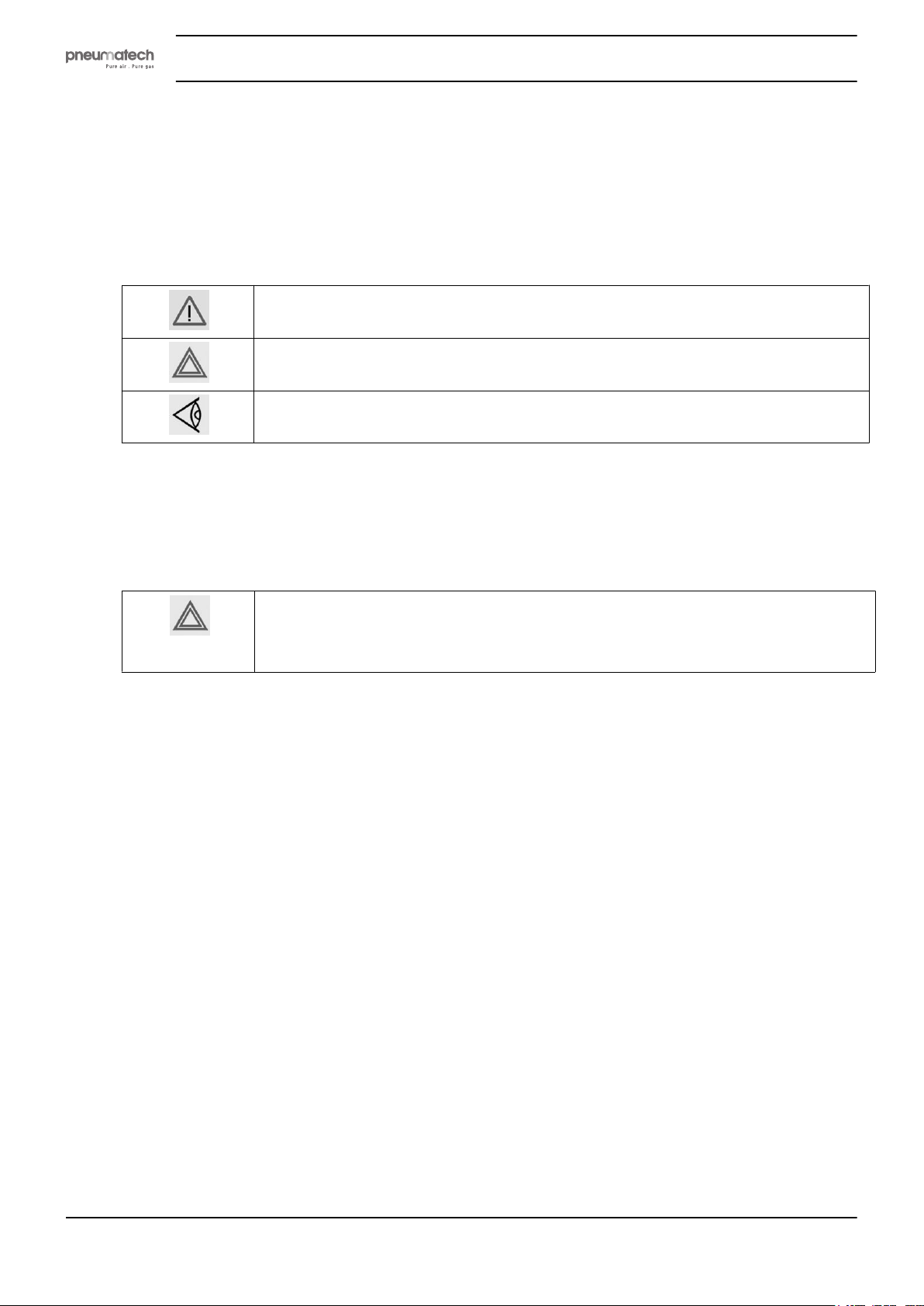
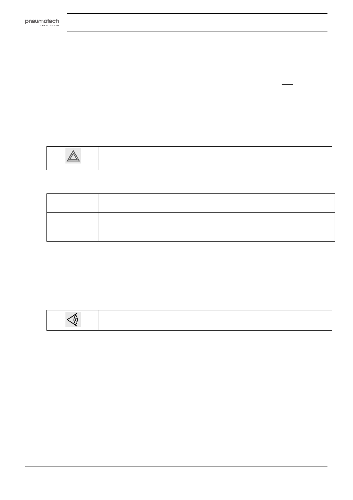
1.1 Safety icons
Explanation
Danger to life
Warning
Important note
Instruction book
1.2 Safety precautions, general
General precautions
All responsibility for any damage or injury resulting from neglecting these precautions, or
non-observance of the normal caution and care required for installation, operation,
maintenance and repair, even if not expressly stated, will be disclaimed by the
manufacturer.
1. The dryers are designed for normal indoor use.
2. The operator must employ safe working practices and observe all related work safety requirements
and regulations.
3. If any of the following statements does not comply with the applicable legislation, the stricter of the
two shall apply.
4. Installation, operation, maintenance and repair work must only be performed by authorized, trained,
specialized personnel.
5. The dryer is not considered capable of producing air of breathing quality. To obtain air of breathing
quality, the compressed air must be adequately purified according to the applicable legislation and
standards.
6. Before any maintenance, repair work, adjustment or any other non-routine checks, stop the dryer,
press the emergency stop button, switch off the voltage and depressurize the dryer. In addition, the
power isolating switch must be opened and locked. For plug versions, remove the plug from the wall
socket and secure it.
7. Never play with compressed air. Do not apply the air to your skin or direct an air stream at people.
Never use the air to clean dirt from your clothes. When using the air to clean equipment, do so with
extreme caution and wear eye protection.
8. The owner is responsible for maintaining the dryer in safe operating condition. Parts and accessories
shall be replaced if unsuitable for safe operation.
9. It is not allowed to walk or stand on the dryer or its components.
4 2920 1891 00
Page 7
Instruction book
1.3 Safety precautions during installation
Precautions during installation
1. The dryer must only be lifted using suitable equipment and in accordance with the applicable safety
regulations. Loose or pivoting parts must be securely fastened before lifting. It is strictly forbidden to
dwell or stay in the risk zone under a lifted load. Lifting acceleration and deceleration must be kept
within safe limits. Wear a safety helmet when working in the area of overhead or lifting equipment.
2. Place the dryer where the ambient air is as cool and clean as possible. If necessary, install a suction
duct. Never obstruct the air inlet. Care must be taken to minimize the entry of moisture at the inlet air.
3. Any blanking flanges, plugs, caps or desiccant bags must be removed before connecting the pipes.
4. Air hoses must be of correct size and suitable for the working pressure. Never use frayed, damaged or
worn hoses. Distribution pipes and connections must be of the correct size and suitable for the
working pressure.
5. The aspirated air must be free of flammable fumes, vapors and particles, e.g. paint solvents, that can
lead to internal fire or explosion.
6. Ensure that all piping is free to expand under heat and that it is not in contact with or close to
flammable materials.
7. No external force may be exerted on the air outlet valve. The connected pipe must be free of strain.
8. If remote control is installed, the machine must bear a clear sign stating "Danger: This machine is
remotely controlled and may start without warning".
The operator has to make sure that the machine is stopped and that the isolating switch is open and
locked before any maintenance or repair. As a further safeguard, persons switching on remotely
controlled machines shall take adequate precautions to ensure that there is no one checking or
working on the machine. To this end, a suitable notice shall be affixed to the starting equipment.
9. The electrical connections must correspond to the applicable codes. The machines must be earthed
and protected against short circuits by fuses in all phases. A lockable power isolating switch must be
installed near the equipment.
10. On machines with automatic start-stop system or if the automatic restart function after voltage failure
is activated, a sign stating "This machine may start without warning" must be affixed near the
instrument panel.
11. Never remove or tamper with the safety devices, guards or insulation fitted on the machine. Every
pressure vessel or auxiliary installed outside the machine to contain air above atmospheric pressure
must be protected by a pressure-relieving device or devices as required.
12. Piping or other parts with a temperature in excess of 80˚C (176˚F) and which may be accidentally
touched by personnel during normal operation must be guarded or insulated. Other high-temperature
piping must be clearly marked.
13. If no safety valve is present in the air net close to the desiccant dryer (e.g. safety valve of
compressor), full flow safety valves must be installed on the dryer vessels.
14. If the maximum pressure of the compressor is higher than the design pressure of the dryer, a full flow
safety valve must be installed between the compressor and the dryer in order to blow off the excessive
pressure in case the safety valve of the dryer should be out of order or blocked.
Also consult following safety precautions: Safety precautions during operation and Safety
precautions during maintenance or repair.
These precautions apply to machinery processing or consuming air or inert gas. Processing
of any other gas requires additional safety precautions typical to the application which are
not included herein.
Some precautions are general and cover several machine types and equipment; hence
some statements may not apply to your machine.
2920 1891 00 5
Page 8
1.4 Safety precautions during operation
Precautions during operation
1. Always be careful when touching any piping or components of the dryer during operation.
2. Use only the correct type and size of hose end fittings and connections. When blowing through a hose
or air line, ensure that the open end is held securely. A free end will whip and may cause injury. Make
sure that a hose is fully depressurized before disconnecting it.
3. Persons switching on remotely controlled machines shall take adequate precautions to ensure that
there is no one checking or working on the machine. To this end, a suitable notice shall be affixed to
the remote start equipment.
4. Never operate the machine when there is a possibility of taking in flammable or toxic fumes, vapors
or particles.
5. Never operate the machine below or in excess of its limit ratings.
6. People staying in environments or rooms where the sound pressure level reaches or exceeds 90 dB(A)
shall wear ear protectors.
7. Periodically check that:
• All guards are in place and securely fastened
• All hoses and/or pipes inside the machine are in good condition, secure and not rubbing
• There are no leaks
• All fasteners are tight
• All electrical leads are secure and in good order
• Safety valves and other pressure relief devices are not obstructed by dirt or paint
• Air outlet valve and air net, i.e. pipes, couplings, manifolds, valves, hoses, etc. are in good
condition, free of wear or abuse
8. If warm cooling air from dryers is used in air heating systems, e.g. to warm up a working area, take
precautions against air pollution and possible contamination of the breathing air.
9. Do not remove any of, or tamper with, the sound dampening material.
10. Never remove or tamper with the safety devices, guards or insulations fitted on the machine. Every
pressure vessel or auxiliary installed outside the machine to contain air above atmospheric pressure
shall be protected by a pressure relieving device or devices as required.
11. Yearly inspect the air receiver. Minimum wall thickness as specified in the instruction book must be
respected. Local regulations remain applicable if they are more strict.
Instruction book
Also consult following safety precautions: Safety precautions during installation and Safety
precautions during maintenance or repair.
These precautions apply to machinery processing or consuming air or inert gas. Processing
of any other gas requires additional safety precautions typical to the application which are
not included herein.
Some precautions are general and cover several machine types and equipment; hence
some statements may not apply to your machine.
1.5 Safety precautions during maintenance or repair
Precautions during maintenance or repair
1. Always use the correct safety equipment (such as safety glasses, gloves, safety shoes, etc.).
2. Use only the correct tools for maintenance and repair work.
3. Use only genuine spare parts.
4. All maintenance work shall only be undertaken when the machine has cooled down.
6 2920 1891 00
Page 9
Instruction book
5. A warning sign bearing a legend such as "Work in progress - do not start" shall be attached to the
starting equipment.
6. Persons switching on remotely controlled machines shall take adequate precautions to ensure that
there is no one checking or working on the machine. To this end, a suitable notice shall be affixed to
the remote starting equipment.
7. Close the dryer air outlet valve before connecting or disconnecting a pipe.
8. Before removing any pressurized component, effectively isolate the machine from all sources of
pressure and relieve the entire system of pressure.
9. Never use flammable solvents or carbon tetrachloride for cleaning parts. Take safety precautions
against toxic vapors of cleaning liquids.
10. Scrupulously observe cleanliness during maintenance and repair. Keep dirt away by covering the
parts and exposed openings with a clean cloth, paper or tape.
11. Never weld on, or in any way modify, pressure vessels.
12. Whenever there is an indication or any suspicion that an internal part of a machine is overheated, the
machine shall be stopped but no inspection covers shall be opened before sufficient cooling time has
elapsed; this to avoid the risk of spontaneous ignition of the oil vapor when air is admitted.
13. Never use a light source with open flame for inspecting the interior of a machine, pressure vessel, etc.
14. Make sure that no tools, loose parts or rags are left in or on the machine.
15. All regulating and safety devices shall be maintained with due care to ensure that they function
properly. They may not be put out of action.
16. Before clearing the machine for use after maintenance or overhaul, check that operating pressures,
temperatures and time settings are correct. Check that all control and shut-down devices are fitted and
that they function correctly.
17. Protect the motor, electrical and regulating components, etc. to prevent moisture from entering them,
e.g. when steam-cleaning.
18. Make sure that all sound-damping material and vibration dampers, e.g. damping material on the
bodywork, is in good condition. If damaged, replace it by genuine material from the manufacturer to
prevent the sound pressure level from increasing.
19. Never use caustic solvents which can damage materials of the air net, e.g. polycarbonate bowls.
20. The following safety precautions are stressed when handling desiccant:
• Take precautions not to inhale desiccant dust.
• Check that the working area is adequately ventilated; if required, use breathing protection.
• Do not overfill the dryer when replacing desiccant.
Also consult following safety precautions: Safety precautions during installation and Safety
precautions during operation.
These precautions apply to machinery processing or consuming air or inert gas. Processing
of any other gas requires additional safety precautions typical to the application which are
not included herein.
Some precautions are general and cover several machine types and equipment; hence
some statements may not apply to your machine.
2920 1891 00 7
Page 10
2 General description
2.1 General description
Introduction
The air dryers described in this book are heatless adsorption dryers, built to remove moisture from
compressed air for industrial purposes. The standard version is intended to reach a pressure dew point
(PDP) of -40 ˚F. There is also a version available for a pressure dew point of -100 ˚F.
All dryers are designed for indoor use.
The dryers described in this book are equipped with a smart controller. A Pressure Dew Point (PDP) sensor
can be installed with a sales kit.
Main parts
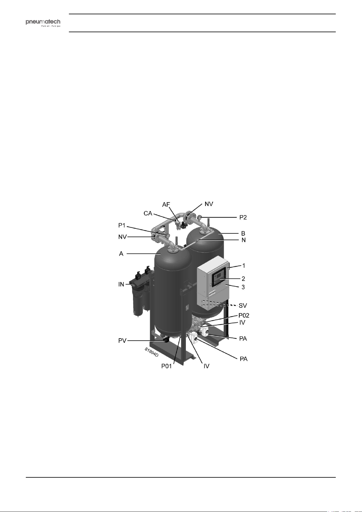
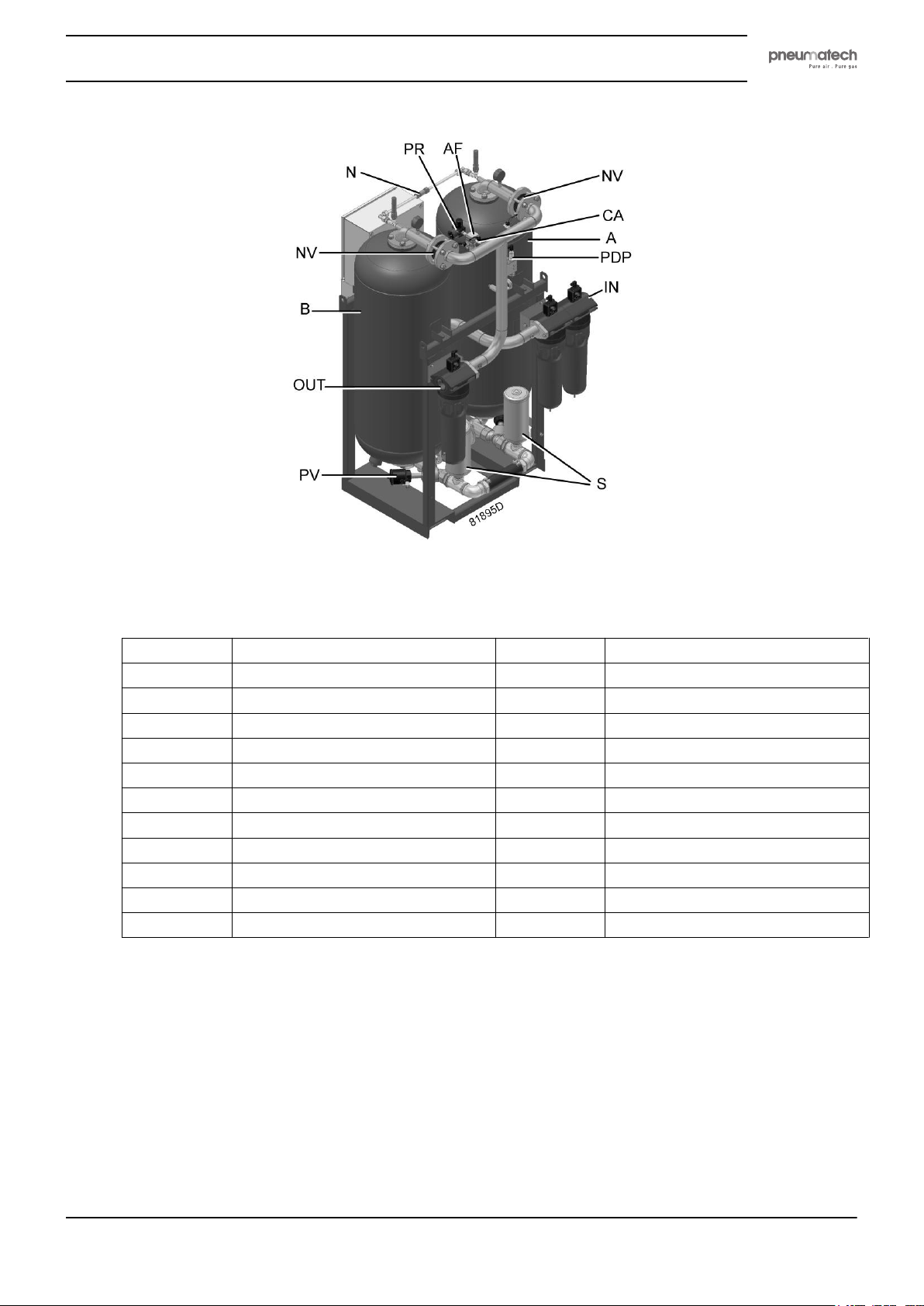
A general overview of the main parts of the dryer units is given in below images:
Instruction book
Front view PH 230 HE up to PH 635 HE
8 2920 1891 00
Page 11
Instruction book
Reference Designation Reference Designation
A Tower A 1 Control panel
B Tower B 2 Purelogic™ controller
IN Dryer inlet 3 Cubicle
OUT Dryer outlet SV Solenoid valves
IV Inlet valve N Nozzle for regeneration air
PA Pneumatic actuator P1 Pressure gauge, tower A
PV Pneumatic valve P2 Pressure gauge, tower B
S Silencer AF Air filter
NV Non-return valve CA Control air valve
PR Pressure regulator (232 psi version) PDP PDP sensor (if installed)
P01 Pressure sensor P02 Pressure sensor
Control panel
The dryer is controlled by a PurelogicTM controller. Consult the dedicated chapter for a complete
description of the controller functions.
Rear view PH 230 HE up to PH 635 HE
Safety valve
If no fire extinguishing system is present close to the dryer, safety valves must be installed on the vessels of
the dryer in order to relieve the overpressure in the vessel because of fire in the neighbourhood of the dryer.
2920 1891 00 9
Page 12

Sonic nozzle (available as an option)
Excessively high air velocity (e.g. due to low inlet pressure) may cause the desiccant to "float" in the
vessels. The desiccant beads scrape against each other, creating additional dust. High-speed flow occurs
when a compressor starts against an empty air net or when working at a discharge air pressure that is too
low. A high volume of compressed air output can result in a pressure drop, which in turn increases the
speed.
Therefore, it is recommended to protect the drying medium against excessive volumetric flow through the
desiccant by installing a sonic nozzle.
Refer to the instruction delivered with the sonic nozzle to install and adjust it.
2.2 Operation
The construction of the air dryer is simple, reliable and easy to service. The dryer has two towers,
containing the adsorbing material or desiccant. The desiccant is a very porous grain material which can
adsorb large amounts of water vapor.
Instruction book
The operation cycle of the dryer is repetitive and is controlled by the Purelogic™ controller and a PDP
(Pressure Dew Point) sensor (when installed and activated).
The compressed air entering the dryer is led to one of the towers by means of the inlet valves (IV), which
are controlled by a pneumatic actuator (PA). As the air flows upwards through the tower, the desiccant
adsorbs the water vapor and the compressed air is dried. The dry air leaves the dryer via the outlet,
connected to the top of the tower.
While the desiccant in the first tower dries the compressed air, the desiccant in the second tower is being
regenerated. Regeneration of the desiccant is achieved by means of purge air from the drying tower: a
small portion of the dried air passes a nozzle (N), expands to atmospheric pressure and flows downwards
through the other tower, regenerating the desiccant. The regenerating air is released via the corresponding
exhaust valve (PV) and the silencer (S).
The regeneration time is regulated by a programmed half cycle time. Solenoid valves, controlled by the
controller, energize the pneumatic valves that determine the function of the towers. In case a PDP sensor is
installed and activated, a second small portion of the dried air flows via the control air valve (100), a small
air filter (101) and the pressure regulator (PR - only used on 232 psi versions) to the PDP sensor.
The PDP sensor constantly measures the pressure dew point of the air leaving the drying tower. As long as
the PDP temperature is below the set point (-40 °F or -100 °F), the drying tower will keep on drying, until
the PDP temperature exceeds the set point. On that moment the regenerated tower will start drying the
compressed air and the other tower will start regenerating. As long as the PDP temperature is below the set
point, regeneration of the non-drying tower is stopped after the pre-set time interval of the timer has
elapsed. As a result, reduction of purge air is achieved.
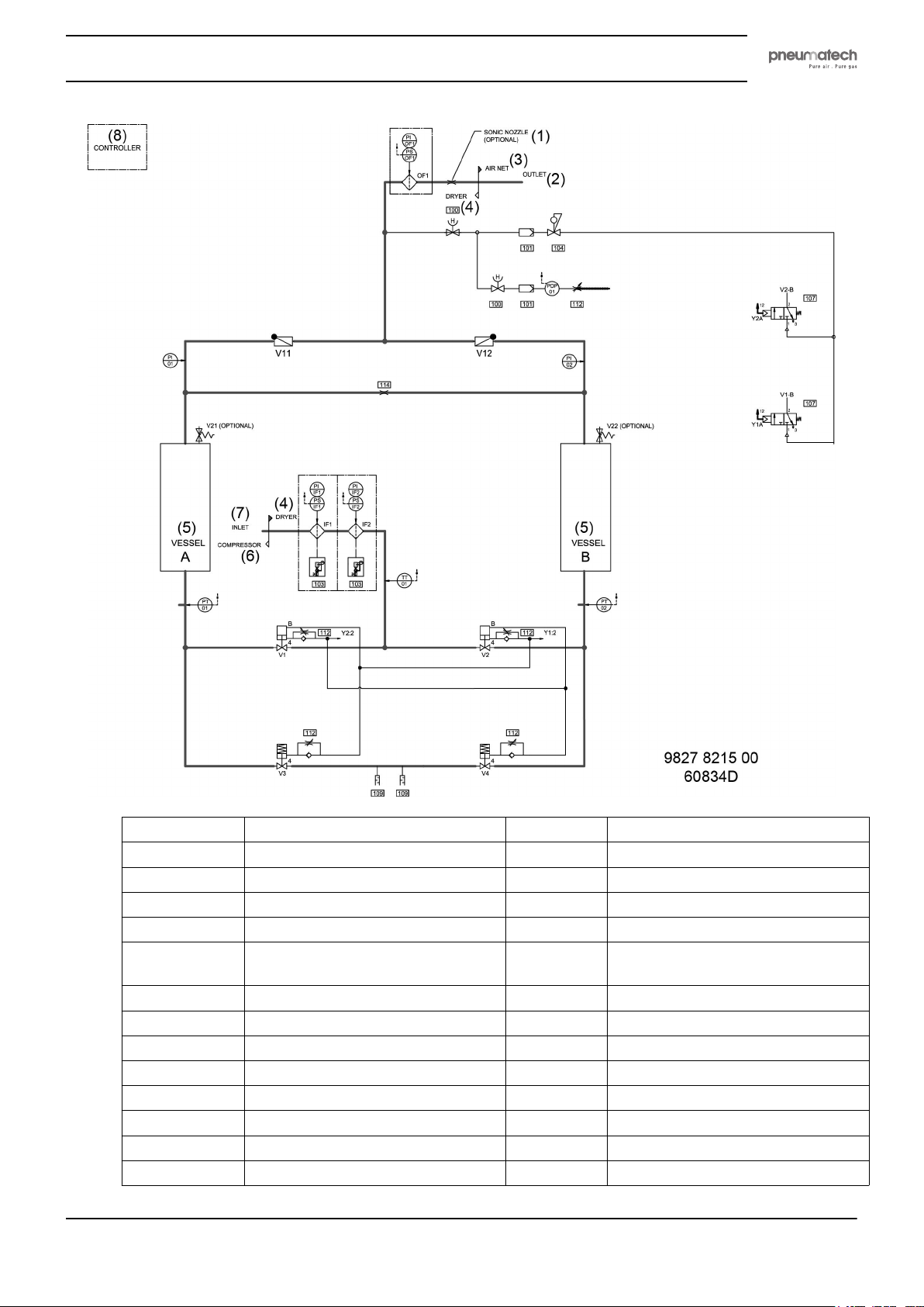
Flow diagram
The figure below shows the pneumatic diagram of the dryer.
10 2920 1891 00
Page 13
Instruction book
Reference Designation Reference Designation
(1) Sonic nozzle (optional) 107 3/2 spool valve monostable
(2) Outlet PS Pressure switch
(3) Air net 100 Manual valve
(4) Dryer 101 Pilot air filter
(5) Vessel 104 Pressure regulator (only on 232 psi
version)
(6) Compressor 112 Adjustable restriction
(7) Inlet 103 Filter with drain
(8) Controller V11/V12 Outlet valve, vessel A/B
PI Pressure indicator 114 Orifice
OF1 Outlet filter IF1/IF2 Inlet filter
V21/V22 Safety valve PT01/PT02 Pressure vessel A/B
PI01/PI02 Pressure indicator, vessel A/B V3/V4 Regulating valve, vessel A/B
V1/V2 Inlet valve, vessel A/B 109 Silencer
2920 1891 00 11
Page 14

Reference Designation Reference Designation
TT01 Inlet temperature PDP01 Pressure Dew Point
Instruction book
12 2920 1891 00
Page 15
Instruction book
3 Electrical diagram
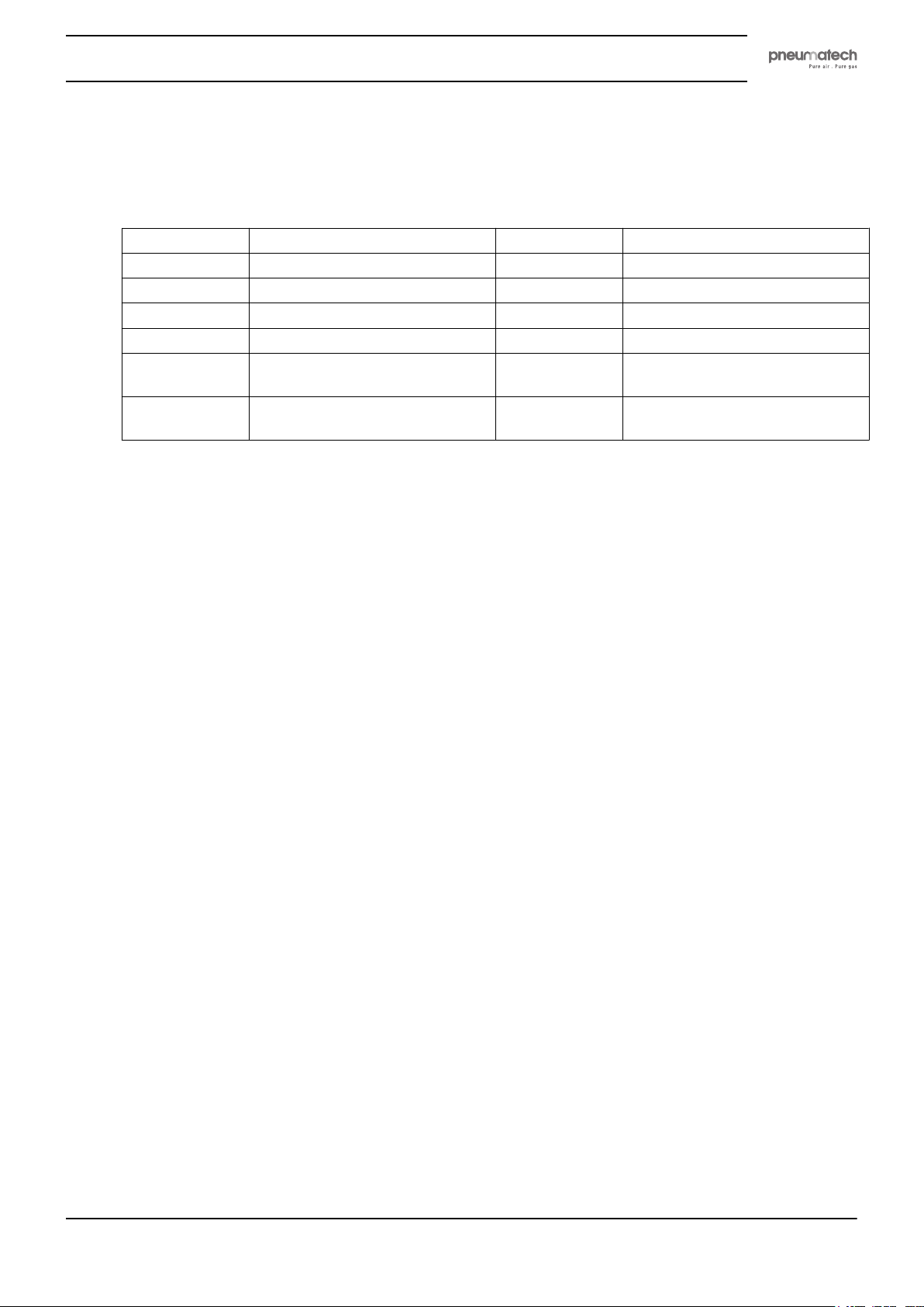
The complete electrical diagram is available inside the electric cabinet.
Some generally used symbols are given in below table:
Reference Designation Reference Designation
F1/2/... Fuses T1 Transformer
Y1/Y2 Solenoid valves MT01 PDP sensor
PT01/PT02 Pressure transducer, Tower A/B TT01 Temperature sensor, inlet
E1 Regulator E2 Expansion module IO2
PDS11/12/13 Pressure drop (ΔP) over filter
(optional)
S1' Remote start/stop switch
(optional)
S0 Main switch (customer's
installation)
S3' Remote emergency stop
(optional)
2920 1891 00 13
Page 16
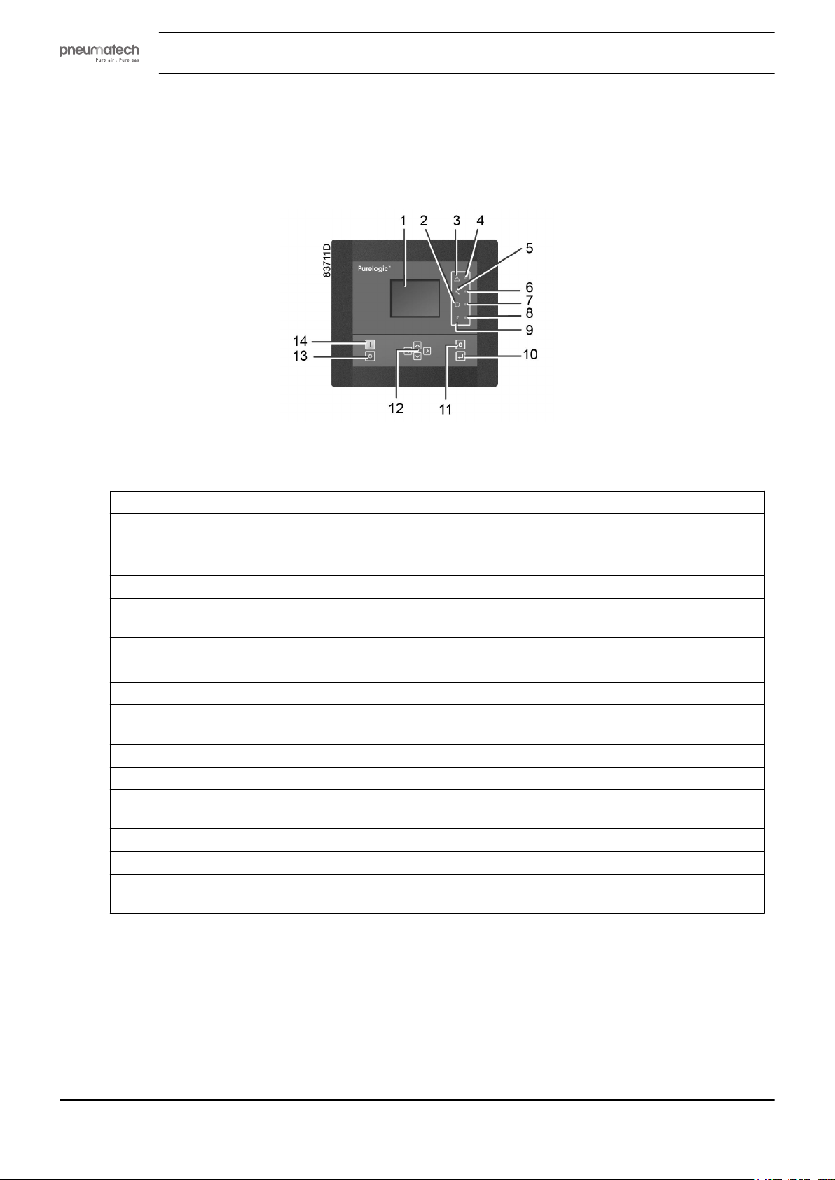
4 Controller
4.1 Control panel
Instruction book
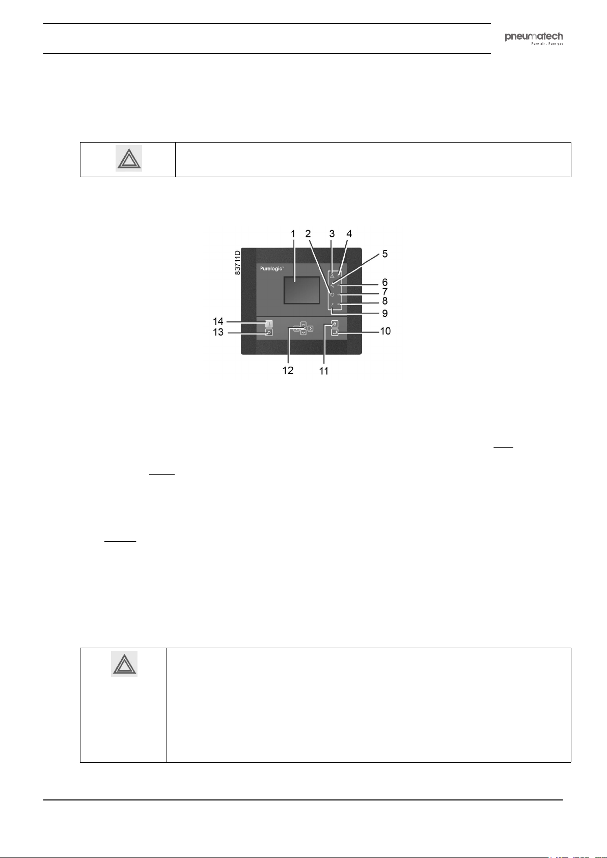
Purelogic controller
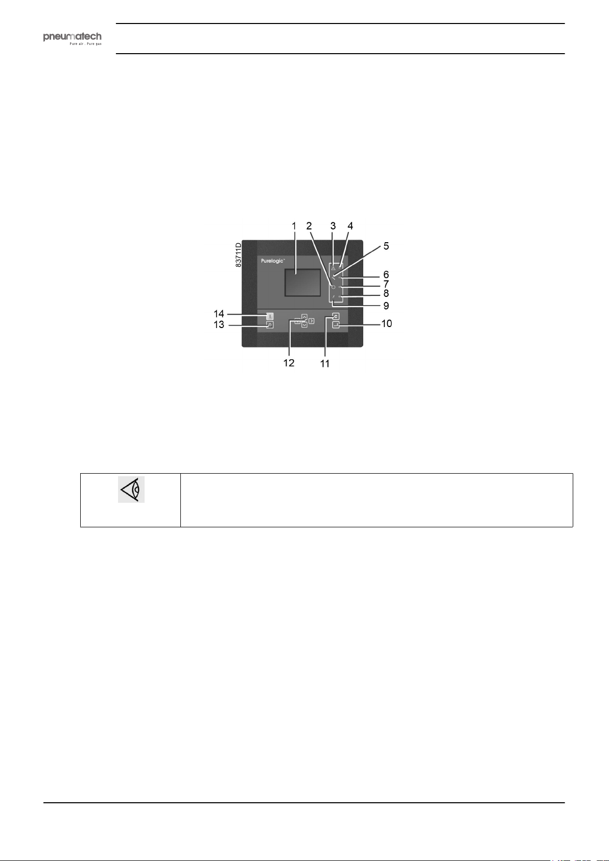
Reference Designation Function
1 Display Shows the dryer operating condition and a number
of icons to navigate through the menu.
2 Pictogram Automatic operation
3 Pictogram General alarm
4 General alarm LED Blinks when operating in shutdown warning
condition.
5 Pictogram Service
6 Service LED Lights up when service is needed.
7 Automatic operation LED Indicates that the controller runs in automatic mode.
8 Voltage on LED Lights up when supply is switched on. Dryer unit
might start automatically!
9 Pictogram Voltage on
10 Enter key Enter and confirmation key
11 Escape key To navigate to previous screen or to cancel current
action
12 Scroll keys Keys to scroll through the menu
13 Stop button Button to stop the dryer. LED (7) dims.
14 Start button Button to start the dryer. LED (7) lights up, indicating
that the controller is operational.
14 2920 1891 00
Page 17
Instruction book
4.2 Digital output contacts
Warning
Voltage-free outputs may only be used to control or monitor functional systems. They
should NOT be used to control, switch or interrupt safety related circuits.
Stop the compressor and switch off the supply before connecting external equipment. Check
the Safety precautions.
Connections for external equipment
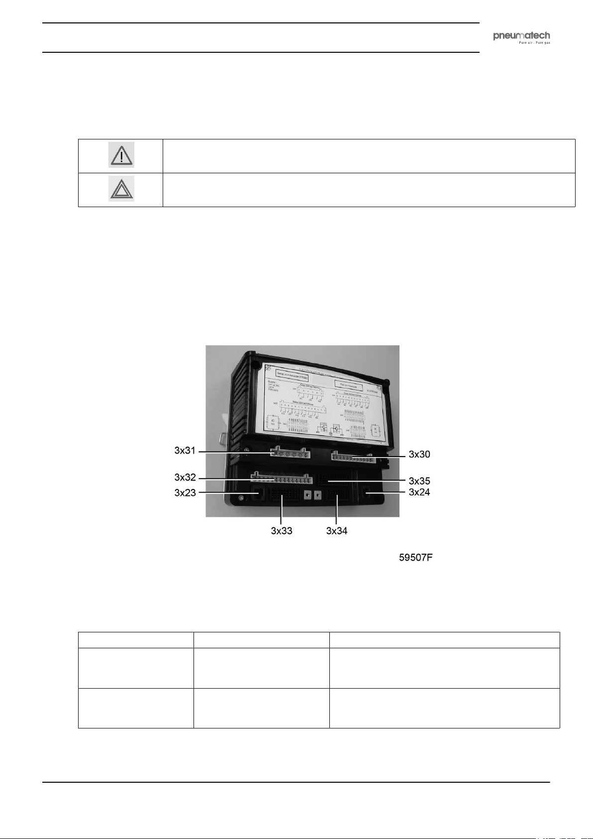
The controller always comes with expansion module IO2 that has a number of digital output contacts
which can be used to connect external equipment.
Depending on the optional equipment, extra expansion modules are added to the machine configuration
(IO2, IO34).
Expansion Module IO2
The digital output contacts have following specifications:
Relay Connector Maximum load
K01 3 X 31 15 A / 250 V AC
15 A / 30 V DC
RC* protected
K02 3 X 31 15 A / 250 V AC
15 A / 30 V DC
RC* protected
2920 1891 00 15
Page 18
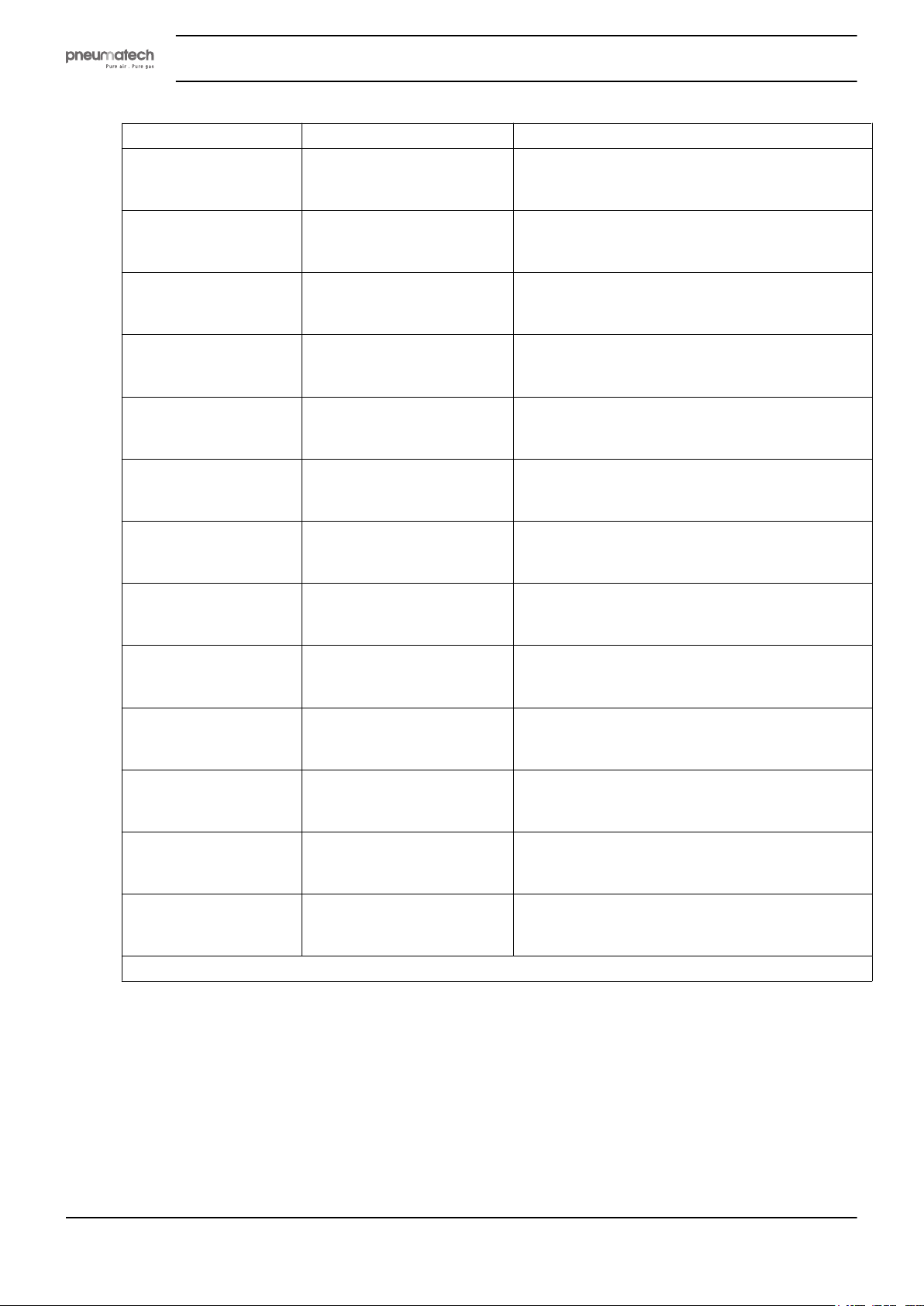
Relay Connector Maximum load
K03 3 X 31 15 A / 250 V AC
15 A / 30 V DC
RC* protected
K04 3 X 31 10 A / 250 V AC
10 A / 30 V DC
resistive load
K05 3 X 30 10 A / 250 V AC
10 A / 30 V DC
resistive load
K06 3 X 30 10 A / 250 V AC
10 A / 30 V DC
resistive load
K07 3 X 30 10 A / 250 V AC
10 A / 30 V DC
resistive load
K08 3 X 30 10 A / 250 V AC
10 A / 30 V DC
resistive load
K09 3 X 30 10 A / 250 V AC
10 A / 30 V DC
resistive load
K10 3 X 32 10 A / 250 V AC
10 A / 30 V DC
resistive load
K11 3 X 32 10 A / 250 V AC
10 A / 30 V DC
resistive load
K12 3 X 32 10 A / 250 V AC
10 A / 30 V DC
resistive load
K13 3 X 32 10 A / 250 V AC
10 A / 30 V DC
resistive load
K14 3 X 32 10 A / 250 V AC
10 A / 30 V DC
resistive load
K15 3 X 32 10 A / 250 V AC
10 A / 30 V DC
resistive load
* = Resistor Capacitor
Instruction book
16 2920 1891 00
Page 19
Instruction book
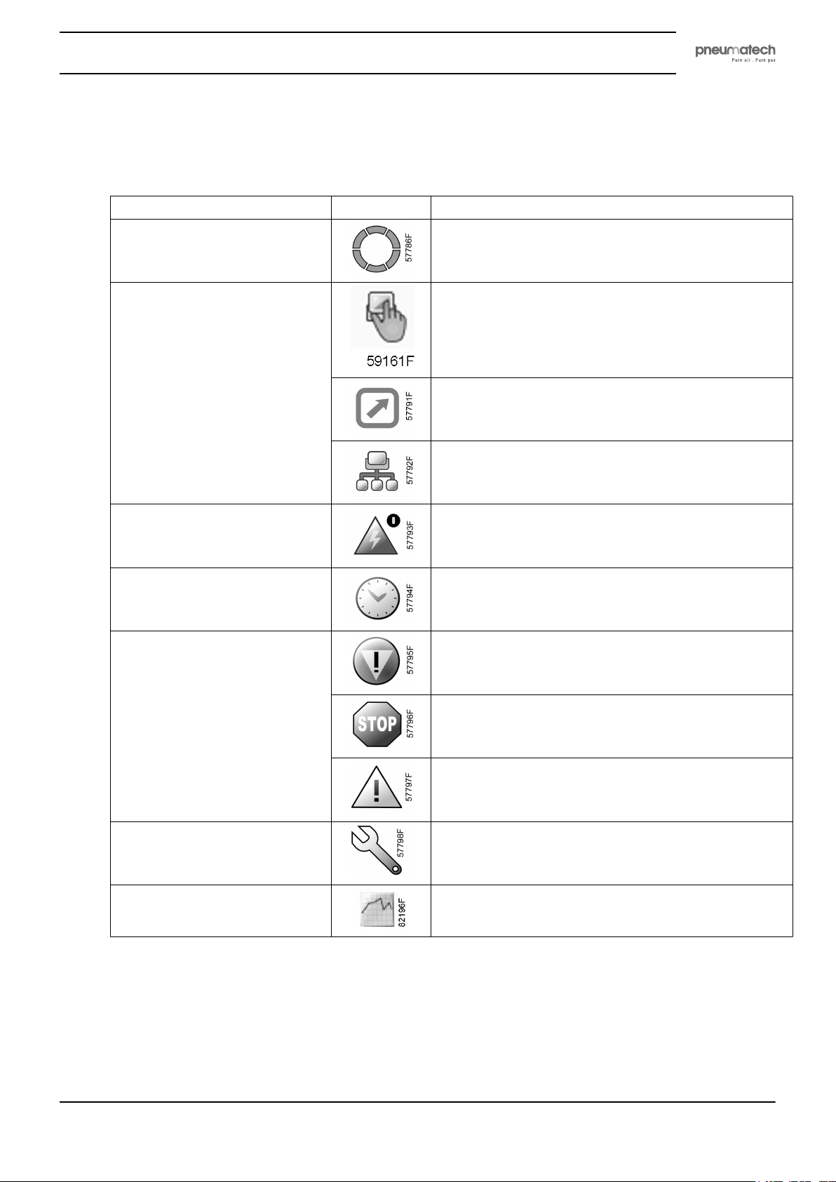
4.3 Icons used
Status icons
Name Icon Description
Stopped/Running When the dryer is stopped, the icon stands still.
Machine control mode Local start/stop
When the dryer is running, the icon is rotating.
Remote start/stop
Network control
Automatic restart after voltage
failure
Week timer Week timer is active
Active protection functions Emergency stop
Service Service required
Main screen Main chart
Automatic restart after voltage failure is active
Shutdown
Warning
2920 1891 00 17
Page 20
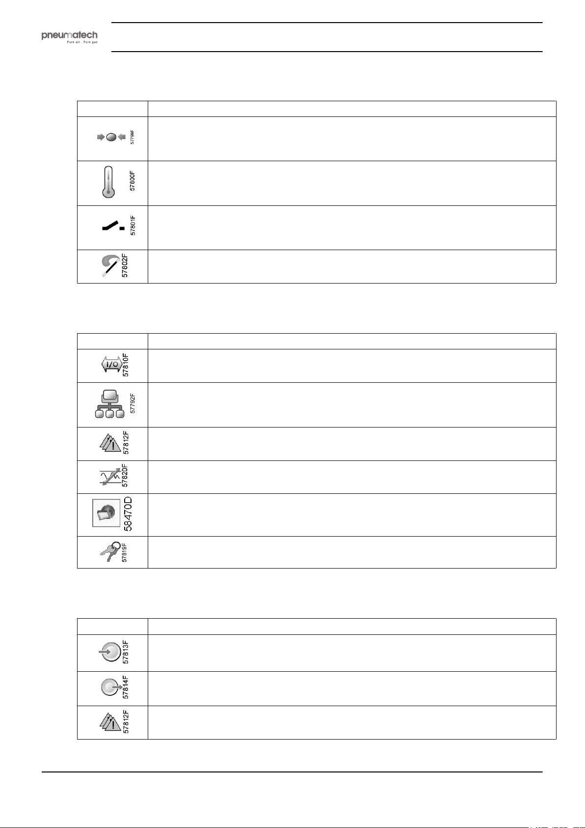
Input icons
Icon Description
System icons
Instruction book
Pressure
Temperature
Digital input
Special protection
Icon Description
Menu icons
Failure expansion module
Network problem
General alarm
Regulation
General settings
Acess key / User password
Icon Description
Inputs
Outputs
Alarms (Warnings, shutdowns)
18 2920 1891 00
Page 21
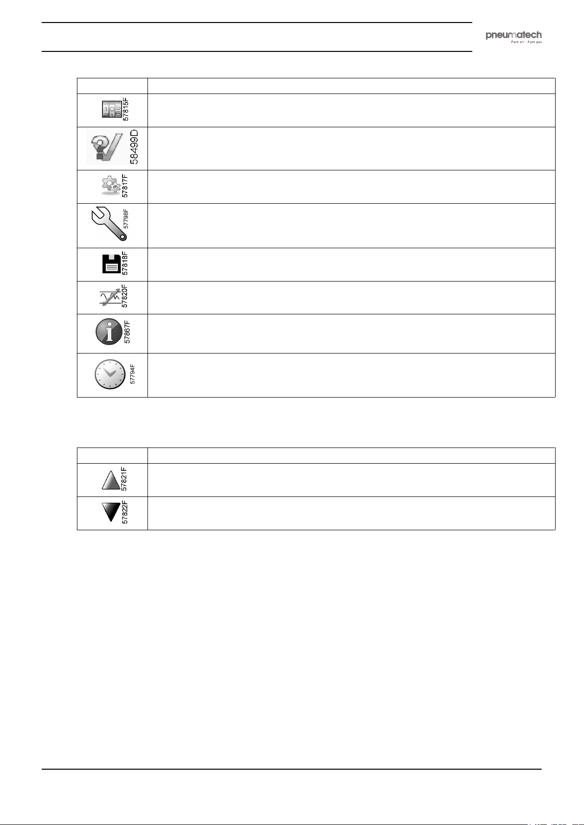
Instruction book
Icon Description
Counters
Test
Settings
Service
Event history (saved data)
Set point
Navigation arrows
Icon Description
Info
Week timer
Up
Down
2920 1891 00 19
Page 22
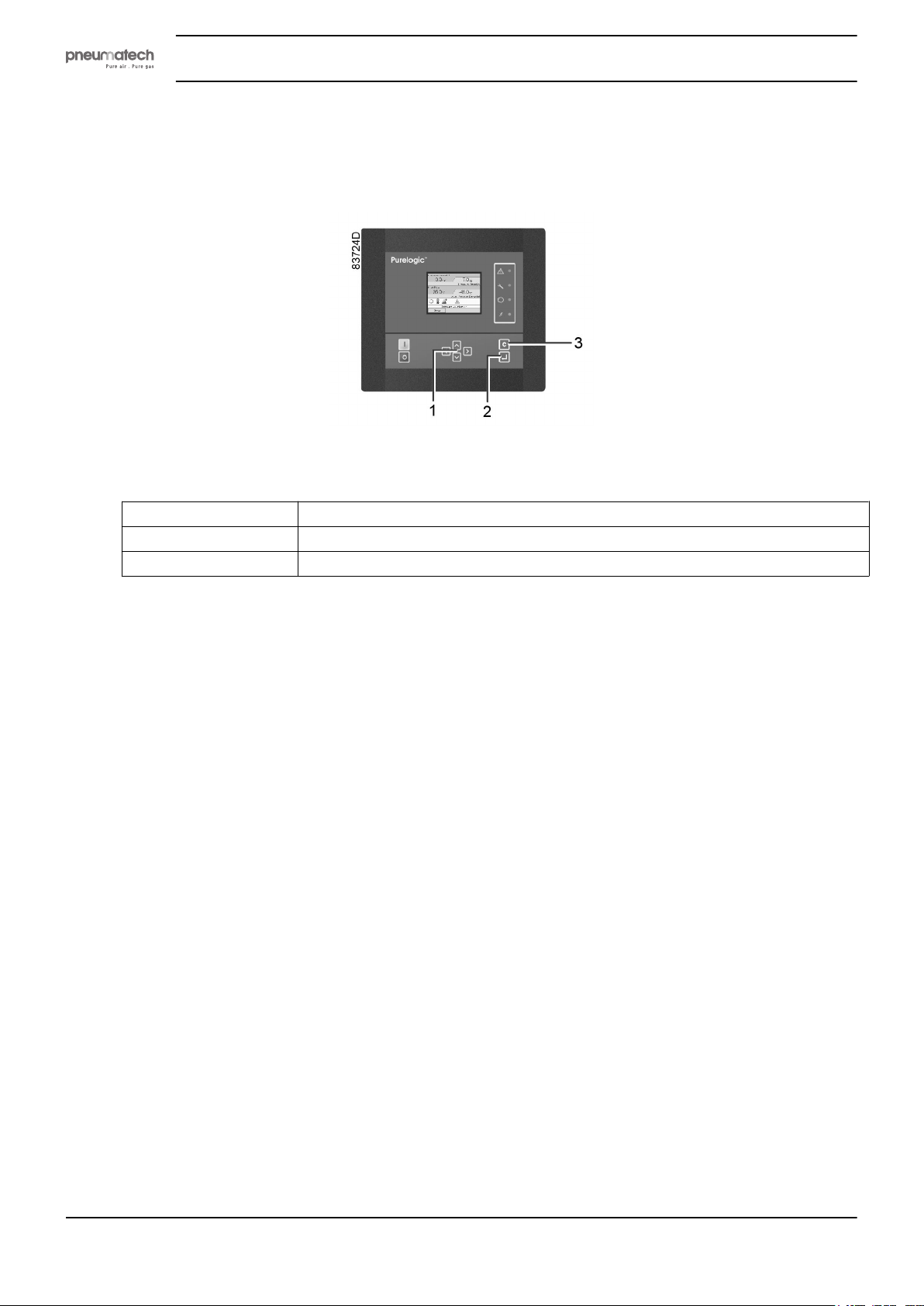
4.4 Main screen
Control panel
Instruction book
Purelogic controller
Function
The main screen shows the status of the dryer and is the gateway to all functionality implemented in the
controller.
The main screen is shown automatically when the power is switched on. The display switches to sleep
mode when no keys are pushed for a programmable time.
Five different main screens can be chosen:
(1) Scroll keys
(2) Enter key
(3) Cancel / Escape key
1. Two value lines
2. Four value lines
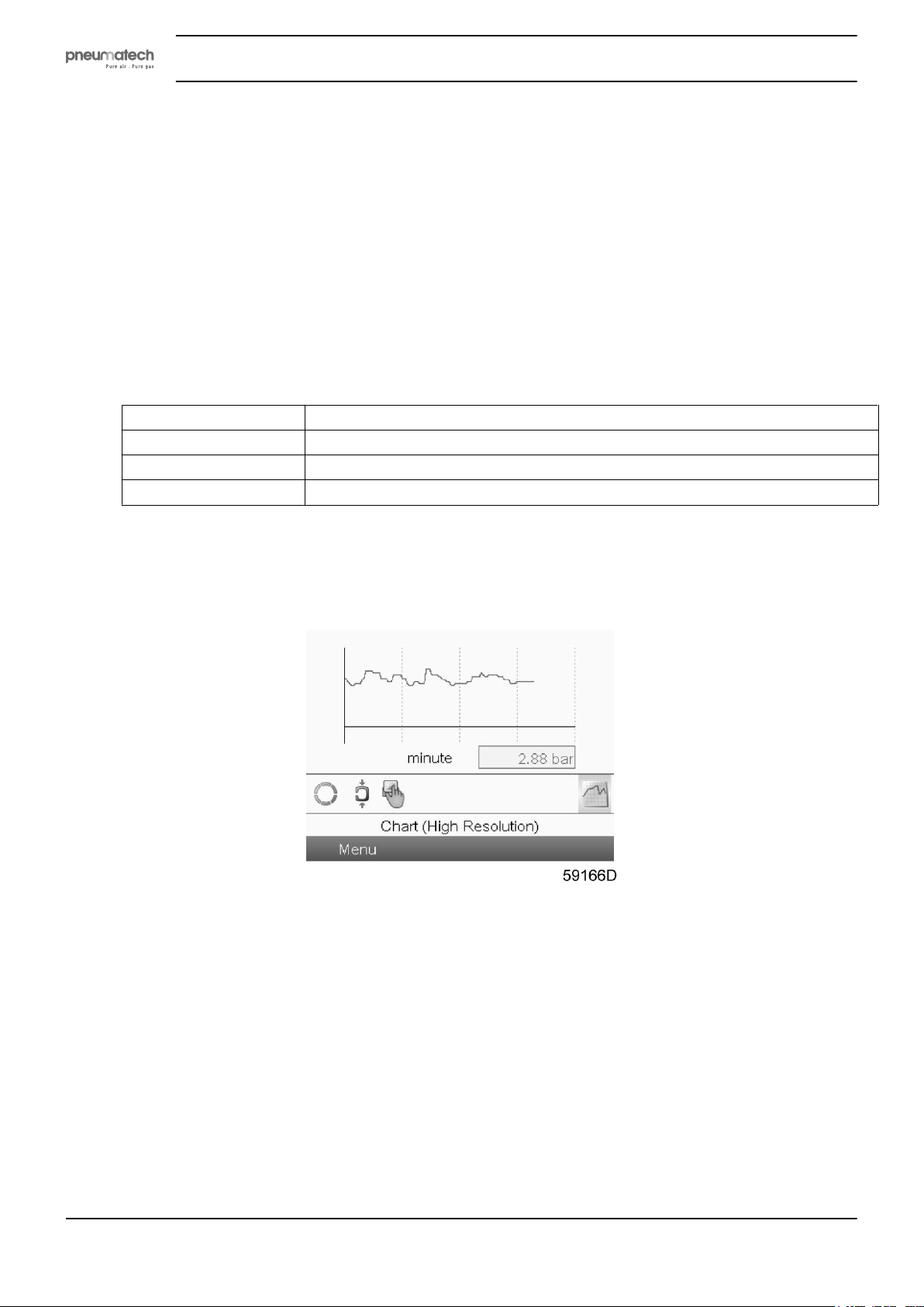
3. Chart (High resolution)
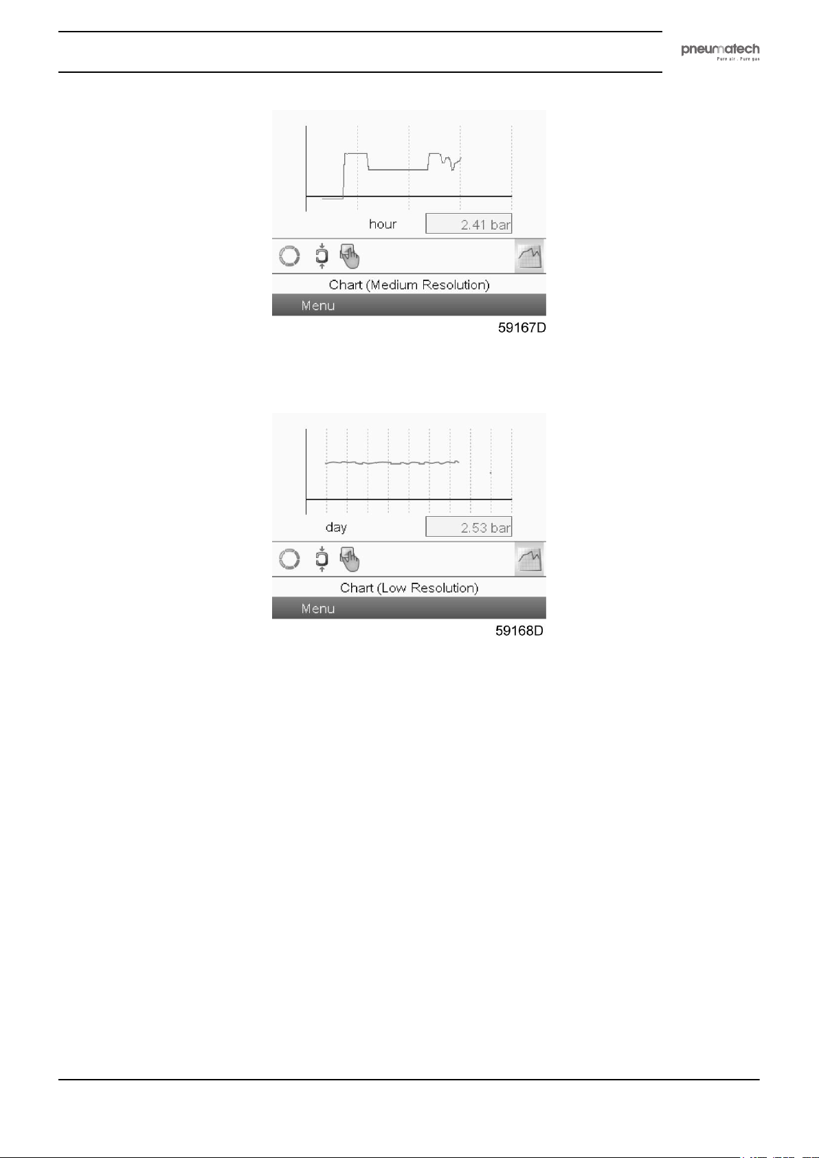
4. Chart (Medium resolution)
5. Chart (Low resolution)
20 2920 1891 00
Page 23
Instruction book
Two and four value views
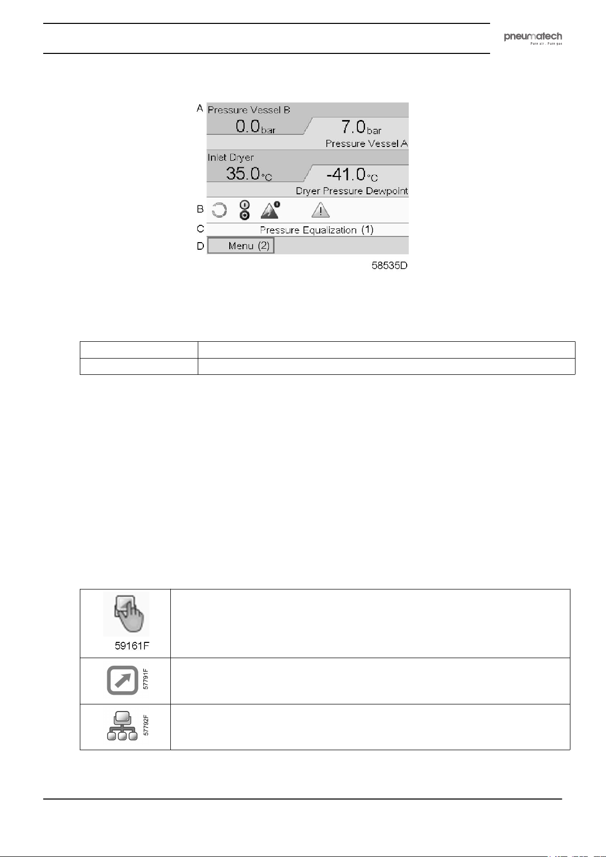
Text on figures
Typical Main screen (Four value lines)
(1)
(2)
Pressure Equalization
Menu
• Section A displays information regarding the dryer operation (e.g. outlet pressure, temperature at
dryer outlet).
• Section B displays Status icons. Following icon types are shown in this field:
• Fixed icons
These icons are always shown in the main screen and cannot be selected by the cursor (e.g.
dryer stopped or running)
• Shortcut icons
These icons are always shown in the main screen. If the icon is selected and the Enter key is
pushed, the screen will jump to the corresponding menu (e.g. if the icon for Motor stopped or
Running Loaded is selected, the screen will jump directly to the regulation menu after pressing
the Enter key).
• Control mode icons
These icons are always shown in the main screen. If the icon is selected and the Enter key is
pushed, the screen jumps to the control mode menu. Following control modes are available:
Local control
Remote control
Network control
• Optional icons
2920 1891 00 21
Page 24
Instruction book
These icons are only shown if their corresponding function is activated (e.g. week timer,
automatic restart after voltage failure, etc.)
• Pop up icons
These icons pop up if an abnormal condition occurs (warnings, shutdowns, service,...)
To show more information about displayed icons, select the icon using the scroll keys and push the
Enter key.
• Section C is called the Status bar
This bar shows the text that corresponds to the selected icon.
• Section D shows the Action buttons. These buttons are used:
• to call-up or program settings
• to reset a shutdown, service message or emergency stop
• to have access to all data collected by the controller
The function of the buttons depends on the displayed menu. The most common functions are:
Designation Function
Menu
Modify
Reset
To go to the menu
To modify programmable settings
To reset a timer or message
Chart views
When the Chart (High Resolution) display is selected, a chart with an X-axis covering 4 minutes is
displayed. The value displayed on the Y-axis depends on the selection made in the input screen. Each chart
dot represents 1 second.
To enable an action button, highlight this button by using the Scroll keys and push the Enter key.
To go back to the previous menu, push the Cancel / Escape key.
22 2920 1891 00
Page 25
Instruction book
When the Chart (Medium Resolution) display is selected, a chart with an X-axis covering 4 hours is
displayed. The value displayed on the Y-axis depends on the selection made in the input screen. Each chart
dot represents a 1 minute average value.
When the Chart (Low Resolution) display is selected, a chart with an X-axis covering 10 days is displayed.
The value displayed on the Y-axis depends on the selection made in the input screen. Each chart dot
represents a 1 hour average value.
4.5 Controller menu structure
Main menu
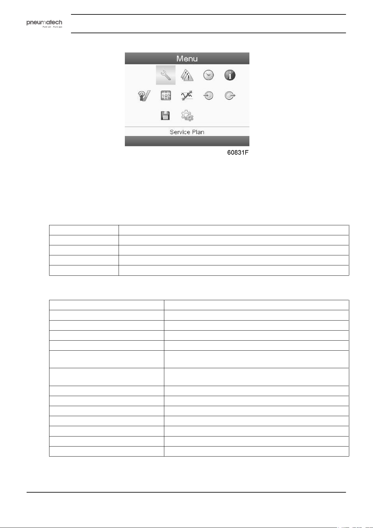
Press the Enter key to go to the main menu screen that is shown below.
2920 1891 00 23
Page 26
Menu structure
Please find the tree structure on the 2 top levels below. The items are mentioned as they appear on the
screen from top to bottom and left to right. If questions regarding lower levels appear, please consult your
local Customer Center.
Instruction book
SERVICE
Topic Description
Overview
Service Plan
Next Service
History
Displays an overview of the running service plans.
Displays configuration of the service plans.
Displays the next service task.
Displays a log of all automatic shutdowns that have appeared in the past.
PROTECTIONS
Topic Description
Emergency Stop
A: High Working Pressure
B: High Working Pressure
Low Dryer Inlet Temperature
A: High Regeneration Temperature
B: High Regeneration Temperature
High Dryer Inlet Temperature
Expansion Module Communication
High Dewpoint
Low Inlet Pressure
Failed to Blow Off Vessel A
Failed to Blow Off Vessel B
Failed to Pressurize
Displays a list of main protections.
Displays the protection of the high working pressure of vessel A.
Displays the protection of the high working pressure of vessel B.
Displays the low inlet protection temperature of the dryer.
Displays the protection of the high regeneration temperature of
vessel A.
Displays the protection of the high regeneration temperature of
vessel B.
Displays the high inlet protection temperature of the dryer.
Displays the protection of the expansion module communication.
Displays the protection of the high dewpoint temperature.
Displays the protection of the low inlet pressure.
Displays the fail to blow off vessel A.
Displays the fail to blow off vessel A.
Displays the fail to pressurize.
WEEK TIMER
24 2920 1891 00
Page 27
Instruction book
Topic Description
Week Action Schemes
Week Cycle
Status
Remaining Running Time
INFORMATION
Topic Description
www.xxxxxxxx.com
More The More button displays the software versions, addresses, licenses, ...
TEST
Displays 4 programmable week action schemes.
Each week action scheme contains 7 programmable days and these days can
contain a number of successive events on selected time slots.
Contains 10 weeks and each week can be selected as 1 of the 4 week action
schemes.
Displays the status (On/Off) of the week timer functionality.
Allows to set a timer to keep the compressor running for 1-240 minutes.
Refers to the company website where more detailed info on the product can be
found.
Topic Description
Output Test
Depressurize Vessels
Allows a functionality check of the output.
Allows a functionality check of the depressurization of the vessels.
COUNTERS
Topic Description
Running Hours Dryers
Loaded Hours Dryers
Standby Time
Actual State time
Programmed State Time
Actual Halve Cycle Time
Programmed Halve Cycle
Time
Regeneration Cycles Vessel
A
Regeneration Cycles Vessel
B
Energy Saving PDP Sensor
Module Hours
Displays the number of hours the dryer has been running.
Displays the number of hours the dryer has been running in loaded mode.
Displays the number of hours the dryer is in stand by.
Displays the number of hours the dryer is in current state.
Displays the number of hours the dryer will be in current state.
Displays the number of hours the dryer is in halve cycle state.
Displays the number of hours the dryer will be in halve cycle state.
Displays the number of regeneration cycles of vessel A.
Displays the number of regeneration cycles of vessel B.
Displays the energy saving percentage with the PDP sensor.
Displays the number of hours the module has been powered.
REGULATION
2920 1891 00 25
Page 28
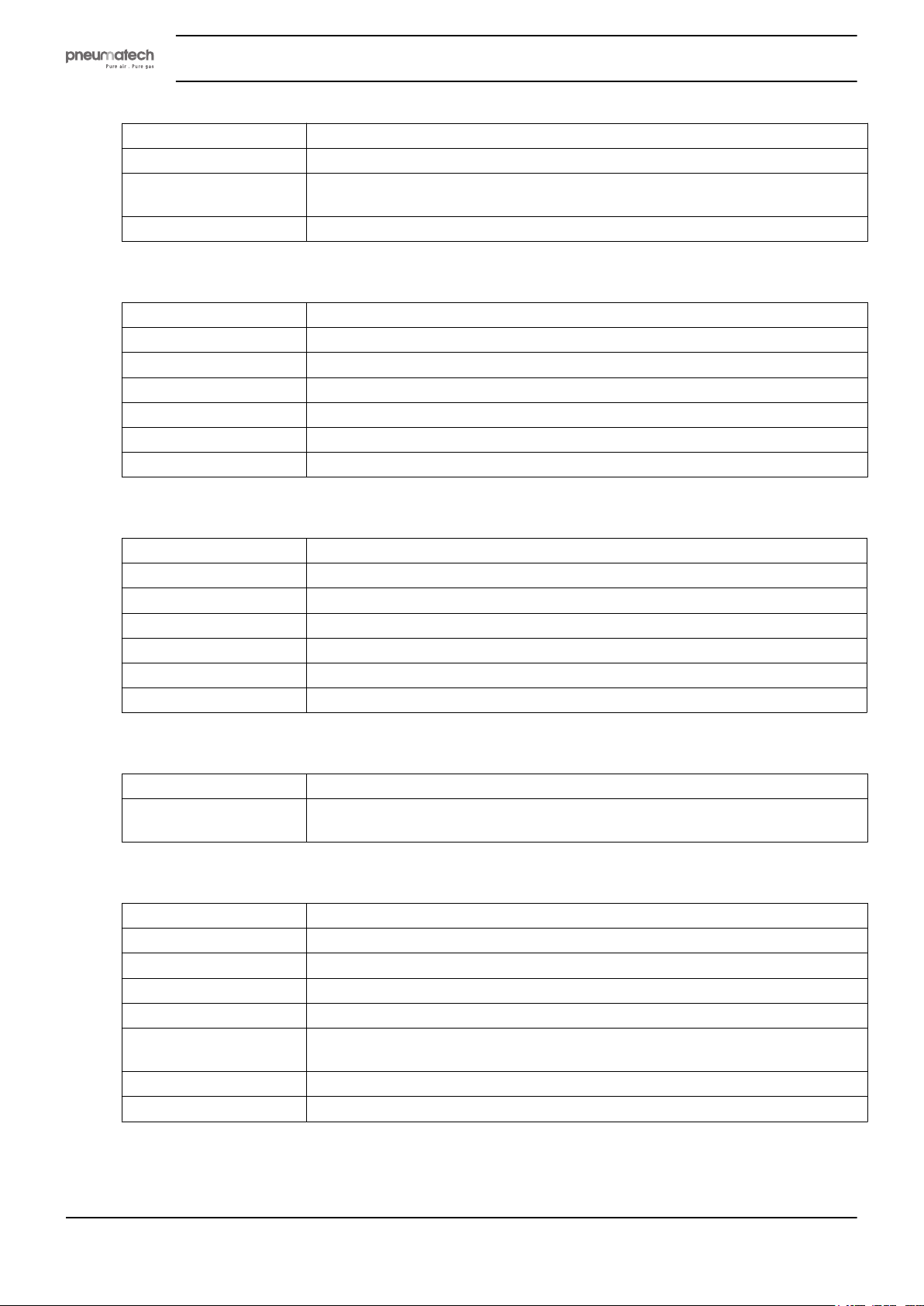
Topic Description
PDP Extended Cycle
PDP Switching
Temperature
PDP Alarm Offset
Displays if the PDP extendend cycle is activated or not.
Displays the PDP switching temperature
Displays the PDP alarm offset
INPUTS
Topic Description
Pressure Vessel A
Pressure Vessel B
Inlet Dryer
Dryer Pressure Dewpoint
Emergency Stop
Remote Start/Stop
Displays the pressure of vessel A.
Displays the pressure of vessel B.
Displays the dryer inlet temperature.
Displays the dryer pressure dewpoint temperature.
Displays the emergency stop status.
Displays the remote start/stop status.
Instruction book
OUTPUTS
Topic Description
Dryer Motor
Low Pressure Alarm
General Shutdown
General warning
Pressure Relief Valve A
Pressure Relief Valve B
Indicates that the dryer is running.
Displays status of low pressure alarm.
Displays status of general shutdown.
Displays status of general warning.
Displays if pressure relief valve A is present.
Displays if pressure relief valve B is present.
EVENT HISTORY
Topic Description
-
Displays a log file of all shutdowns and shows the status of the type, counters,
inputs and outputs at the moment a shutdown appeared
SETTINGS
Topic Description
Network
General
Regulation
Remote Control
Automatic Restart
Access Key
Main Chart
Displays the CAN and ethernet configuration
Displays settings concerning time, date, unit and display time-out
Displays settings concerning the compressed air flow regulation
Displays setting concerning the remote control
Automatic Restart After Voltage Failure can only be enabled by a service
technician.
Displays the controller access level that can be modified with password input
Displays the input and the range of the main chart
26 2920 1891 00
Page 29
Instruction book
4.6 Test menu
Controller
Menu icon, Test
Function
Procedure
Starting from the Main screen (see Main screen):
• To depressurize the vessels and to test the output contacts.
• The vessels can only be depressurized when the dryer is stopped (off state).
• The test procedure will be stopped as soon as another menu is selected on the
regulator.
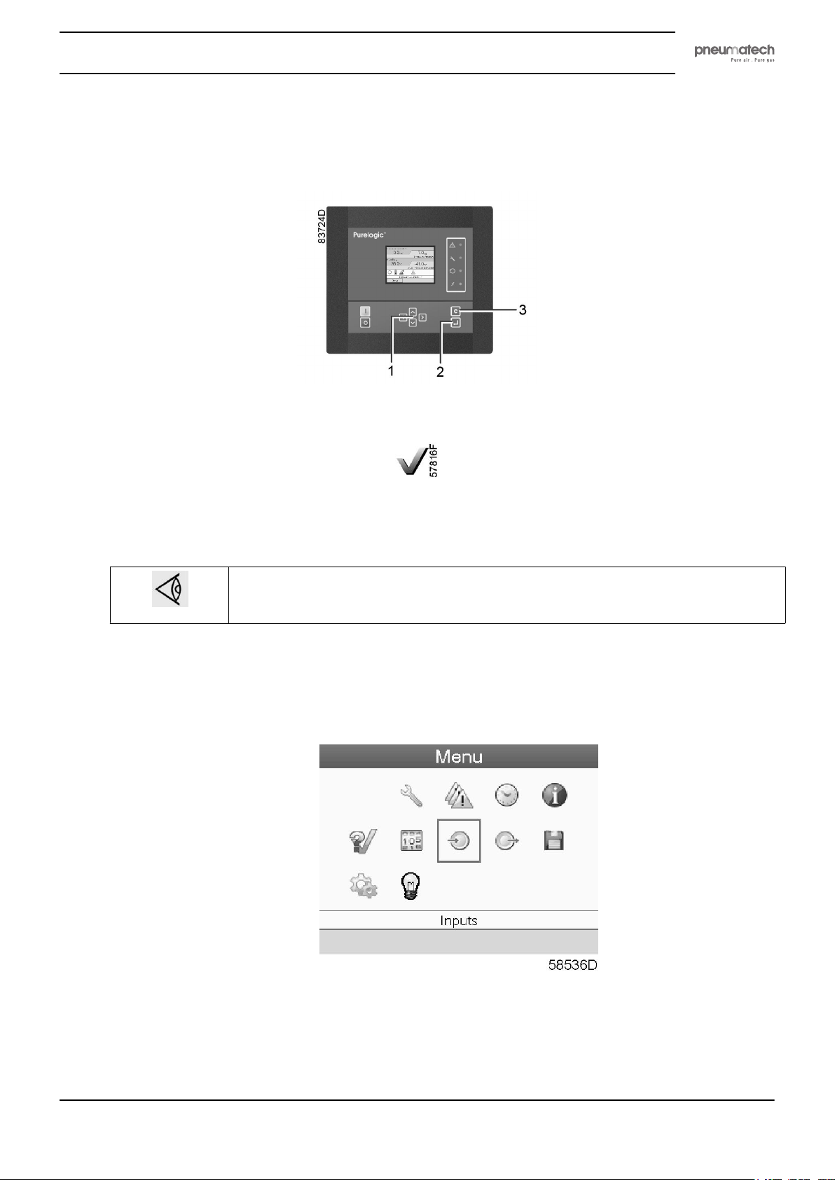
• Move the cursor to the Menu action button and press the enter key (2); following screen appears:
• Using the scroll keys (1), move the cursor to the test icon (see above, section Menu icon).
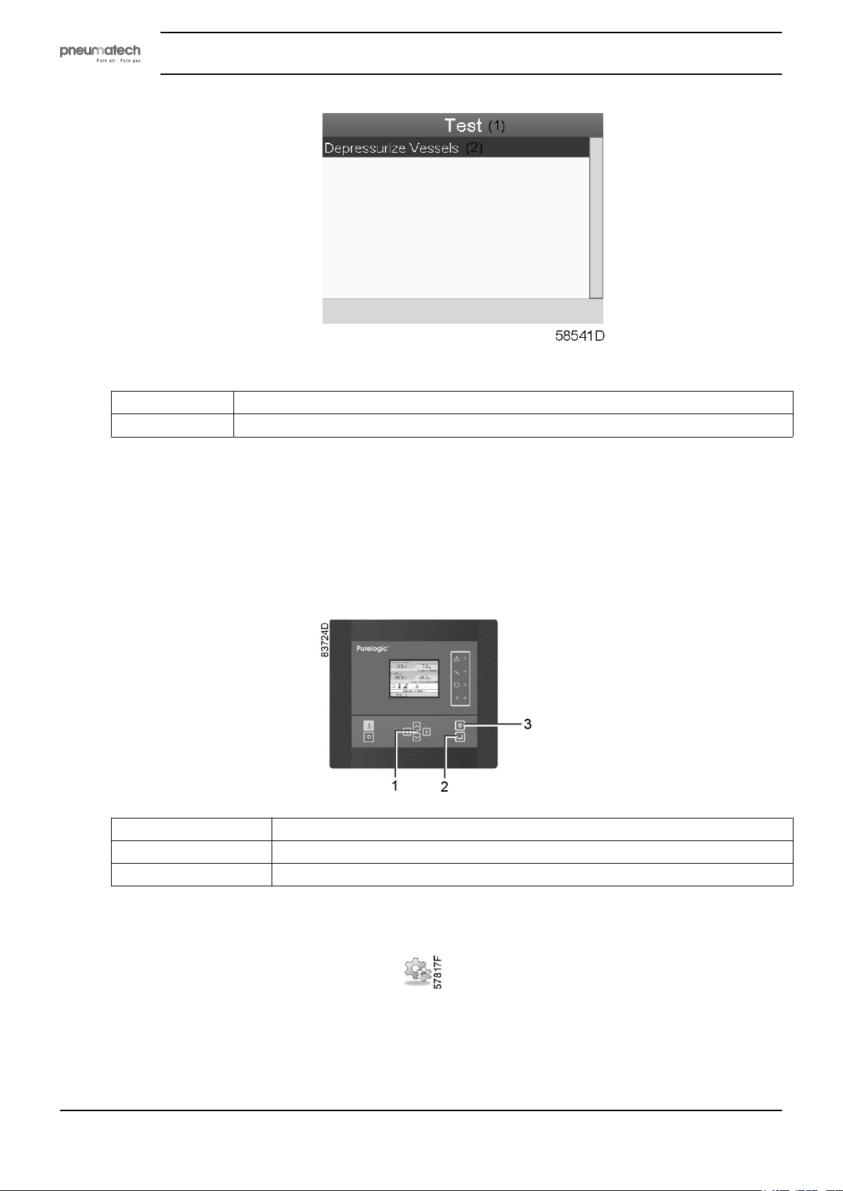
• Press the enter key (2); following screen appears:
2920 1891 00 27
Page 30
Text on figure
Instruction book
(1)
(2)
Test
Depressurize vessels
• A red selection bar is covering the item Depressurize vessels ; press the Enter key to depressurize the
vessels.
4.7 Modifying settings
Controller
(1) Scroll keys
(2) Enter key
(3) Escape key
Menu icon, Settings
Function
To display and modify a number of settings (e.g. Time, Date, Date format, Language, units ...).
28 2920 1891 00
Page 31
Instruction book
Procedure
Starting from the Main screen (see Main screen),
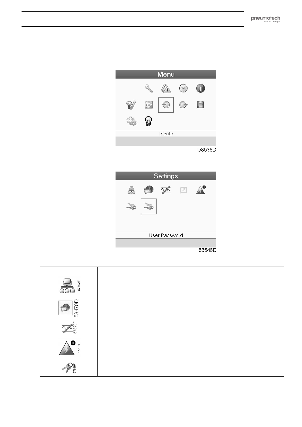
• Move the cursor to the Menu action button and press the Enter key. Following screen appears:
• Using the Scroll keys, move the cursor to the Settings icon (see above, section menu icon).
• Press the Enter key. Following screen appears:
• The screen shows a number of icons:
Icon Function
Network settings
General settings
Regulation settings
Automatic restart after voltage failure settings
Access key
2920 1891 00 29
Page 32
Icon Function
• Move the cursor to the icon of the function to be modified and press the Enter key.
Modifying network settings
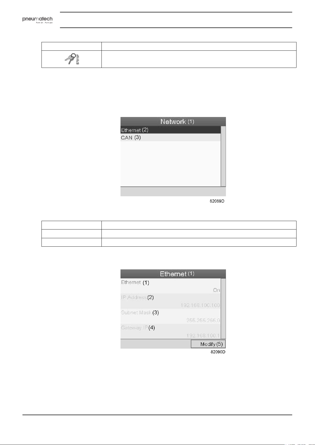
• Select the network settings icon as described above and press the Enter button (2). Following screen
appears:
Instruction book
User password
Text on figure
(1)
(2)
(3)
Network
Ethernet
CAN
• A red selection bar is covering the first item (Ethernet). Use the ↓ key of the Scroll keys to select the
setting to be modified and press the Enter key. Following screen appears:
Screen for Ethernet settings
30 2920 1891 00
Page 33
Instruction book
Text on figure
(1)
(2)
(3)
(4)
(5)
Ethernet
IP Address
Subnet mask
Gateway IP
Modify
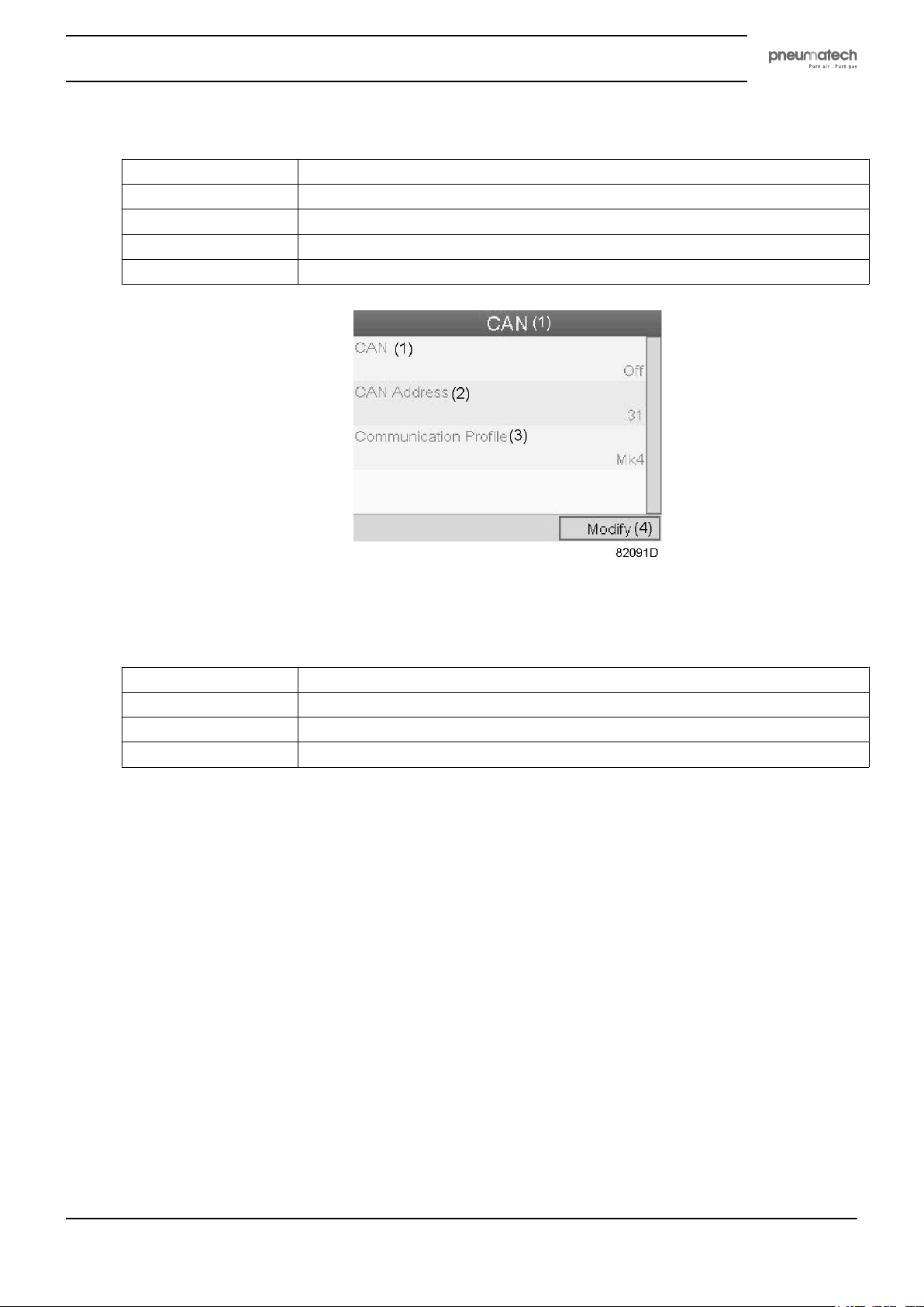
Screen for CAN settings
Text on figure
(1)
(2)
(3)
(4)
• Press the Enter button; a red selection bar is covering the first item (Ethernet ).
• Using the Scroll keys, move the cursor to the setting to be modified (e.g. Ethernet ) and press the
Enter button (2).
• A pop-up screen appears. Use the ↑ or ↓ key to select the required parameter and press the Enter key
to confirm.
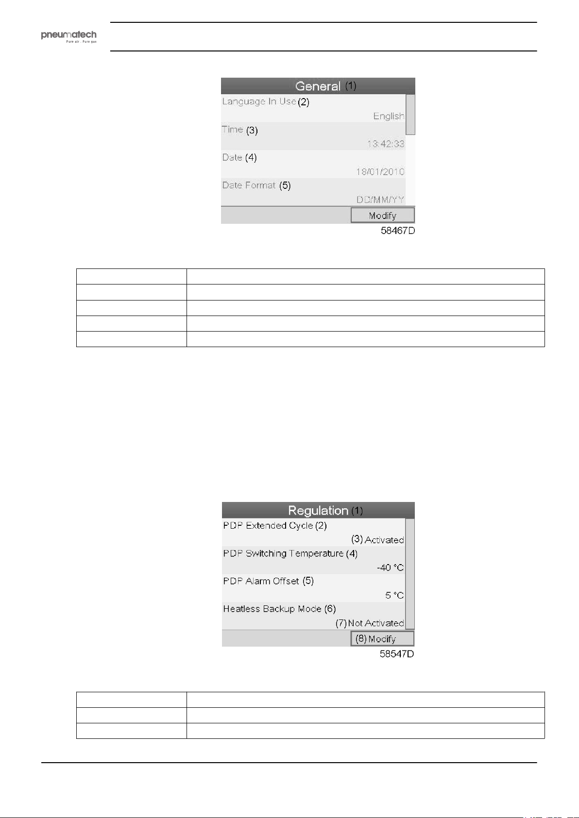
General settings
• Select the General settings icon as described above and press the Enter button (2). Following screen
appears:
CAN
CAN Address
Communication profile
Modify
2920 1891 00 31
Page 34
Text on figure
Instruction book
(1)
(2)
(3)
(4)
(5)
• The screen shows the first items of a list of all settings. Use the scroll button to see the other items in
the list.
• Press the Enter button (2); a red selection bar is covering the first item (Language in use).
Use the ↓ key of the Scroll keys to select the setting to be modified and press the Enter key.
• A pop-up screen appears. Use the ↑ or ↓ key to select the required parameter and press the Enter key
to confirm.
Regulation settings
• Select the Regulation icon as described above and press the Enter button (2). Following screen
appears:
General
Language in use
Time
Date
Date format
Text on figure
(1)
(2)
(3)
32 2920 1891 00
Regulation
PDP extended cycle
Activated
Page 35
Instruction book
(4)
(5)
(6) Heatless backup mode (see note *)
(7)
(8)
PDP switching temperature
PDP Alarm offset
Not activated
Modify
*: not applicable.
• The screen shows the list of all settings.
• Press the Enter button (2); a red selection bar is covering the first item (PDP extended cycle).
Use the ↓ key of the Scroll keys to select the setting to be modified and press the Enter key.
• A pop-up screen appears. Use the ↑ or ↓ key to select the required parameter and press the Enter key
to confirm.
Regulation settings:
• PDP extended cycle: the cycle is lengthened by putting the vessel in waiting mode (standby) if PDP
is low enough after regeneration and cooling. The extended cycle should only be activated when a
working PDP sensor is present.
• PDP switching temperature: the PDP should not increase to this setting before the vessels are
switched when the dryer is in standby mode.
• PDP Alarm offset: the PDP alarm is active when: PDP > PDP_switching_temperature +
PDP_alarm_offset. In that way, the alarm threshold can be set independently of the switching
threshold.
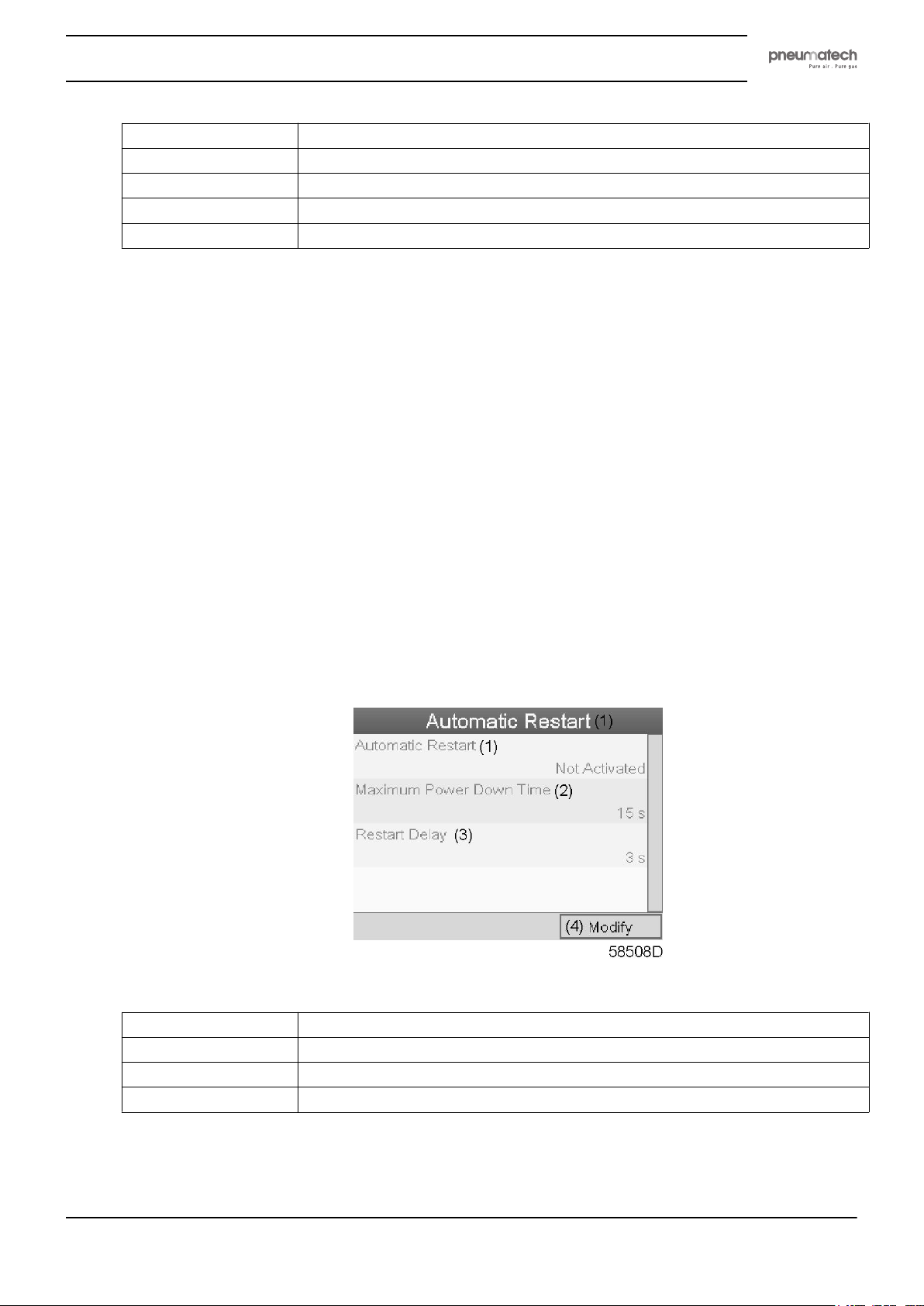
Automatic restart
• Select the Automatic restart settings icon as described above and press the Enter button (2).
Following screen appears:
Text on figure
(1)
(2)
(3)
(4)
Automatic restart (Not Activated)
Maximum power down time
Restart delay
Modify
• The screen shows the list of all settings.
• Press the Enter button (2); a red selection bar is covering the first item (Automatic restart).
Use the ↓ key of the Scroll keys to select the setting to be modified and press the Enter key.
2920 1891 00 33
Page 36
• A pop-up screen appears. Use the ↑ or ↓ key to select the required parameter and press the Enter key
to confirm.
Access key
Different security levels are programmed in the regulator (e.g. user, service technician, etc). This menu
item is used to change the security level. Scroll to the correct icon using the scroll key. Press the Enter
button. Press the Enter button again to modify the security level. Press the Enter button again, a pop-up
menu appears. Use the scroll keys to enter the password of the new security level. Press the Enter key to
confirm the change.
User password
If the password option is activated, it is impossible for not authorized persons to modify any setting.
• Using the Scroll keys, move the cursor to the Password icon.
• Press the Enter key.
• Select the Modify button using the Scroll keys and press the Enter key. Next, modify the password as
required.
Instruction book
4.8 Web server
All controllers have a built-in web server that allows direct connection to the company network or to a
dedicated PC via a local area network (LAN). This allows to consult certain data and settings via a PC
instead of the display of the controller.
Getting started
Make sure you are logged in as administrator.
• Use the internal network card from your computer or a USB to LAN adapter.
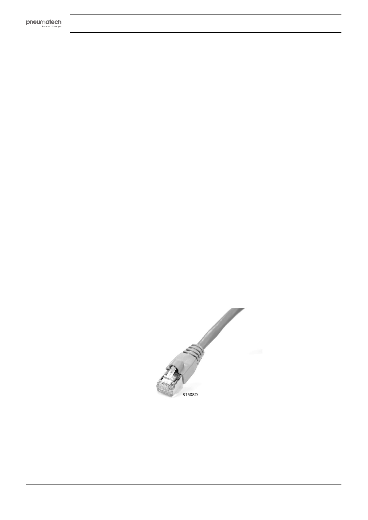
• Use a UTP cable (CAT 5e) to connect to the controller (see picture below).
Configuration of the network card
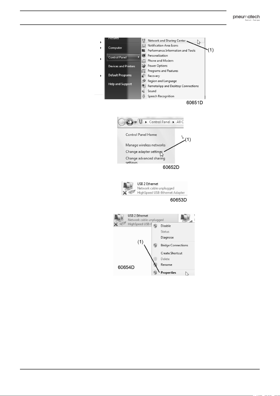
• Go to Network and Sharing Center (1).
34 2920 1891 00
Page 37
Instruction book
• Click on Change adapter settings (1).
• Select the Local Area Connection, which is connected to the controller.
• Click with the right button and select Properties (1).
• Use the check box Internet Protocol version +4 (TCP/IPv4) (1) (see picture). To avoid conflicts,
uncheck other properties if they are checked. After selecting TCP/IPv4, click on the Properties button
(2) to change the settings.
2920 1891 00 35
Page 38
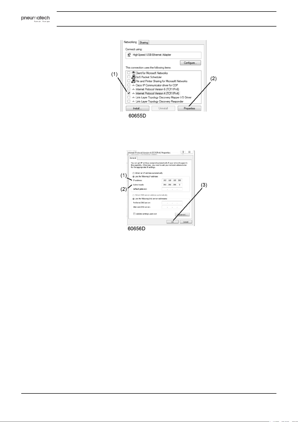
• Use the following settings:
• IP Address 192.168.100.200 (1)
• Subnetmask 255.255.255.0 (2)
Click OK (3) and close network connections.
Instruction book
Configure a company network (LAN) connection
• Ask your IT department to generate a fixed IP address in your company’s network.
• That IP address will be excluded from the DNS server, so it will be reserved for the controller.
• Also get the correct Gateway and Subnet mask settings. For example:
• IP = 10.25.43.200
• Gateway = 10.25.42.250
• Subnet mask = 255.255.254.0
• Connect the controller to the company's network (LAN) by using a UTP cable (min. CAT 5e).
36 2920 1891 00
Page 39
Instruction book
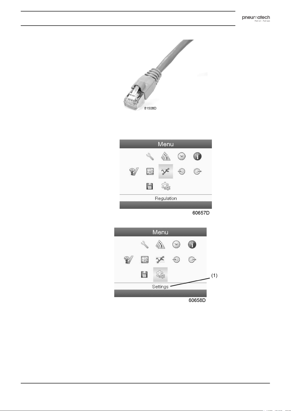
• Adapt the network settings in the controller:
• Go to Main Menu
• Go to Settings (1)
• Go to Network (1)
2920 1891 00 37
Page 40
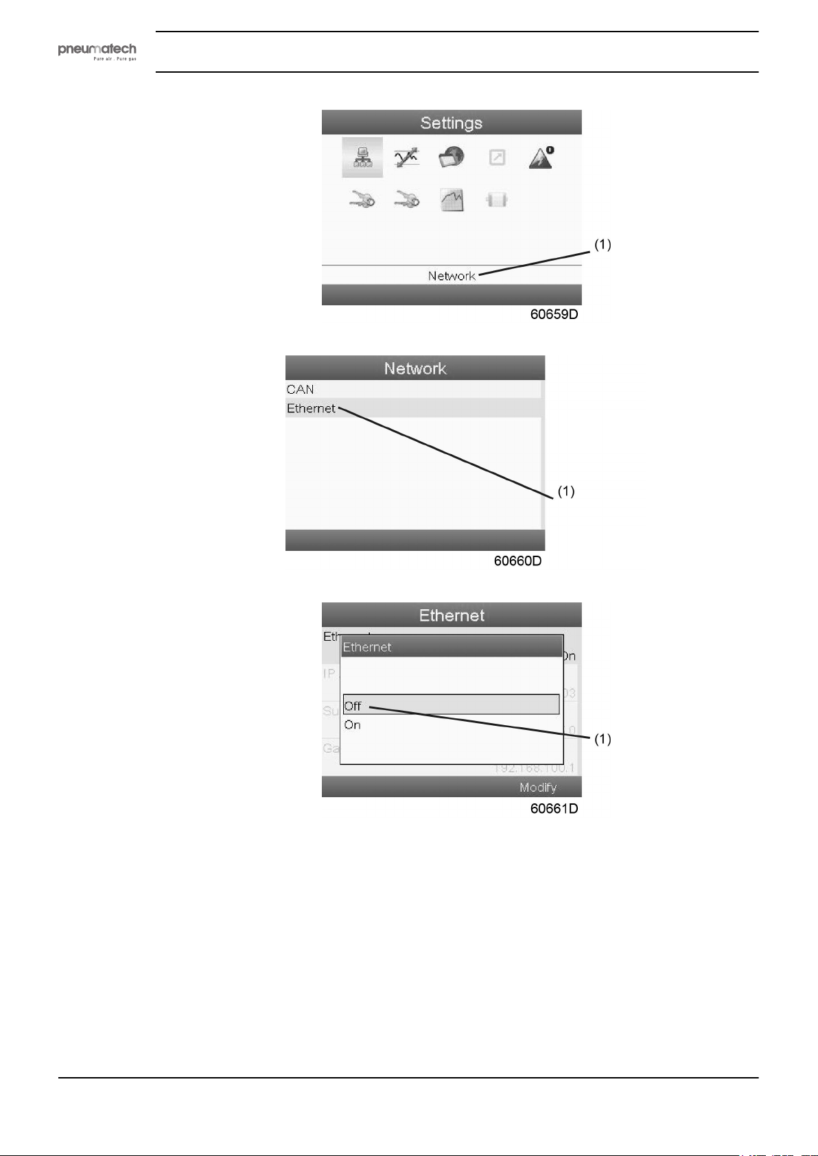
• Go to Ethernet (1)
Instruction book
• Switch Off (1) the Ethernet communication to allow editing the settings
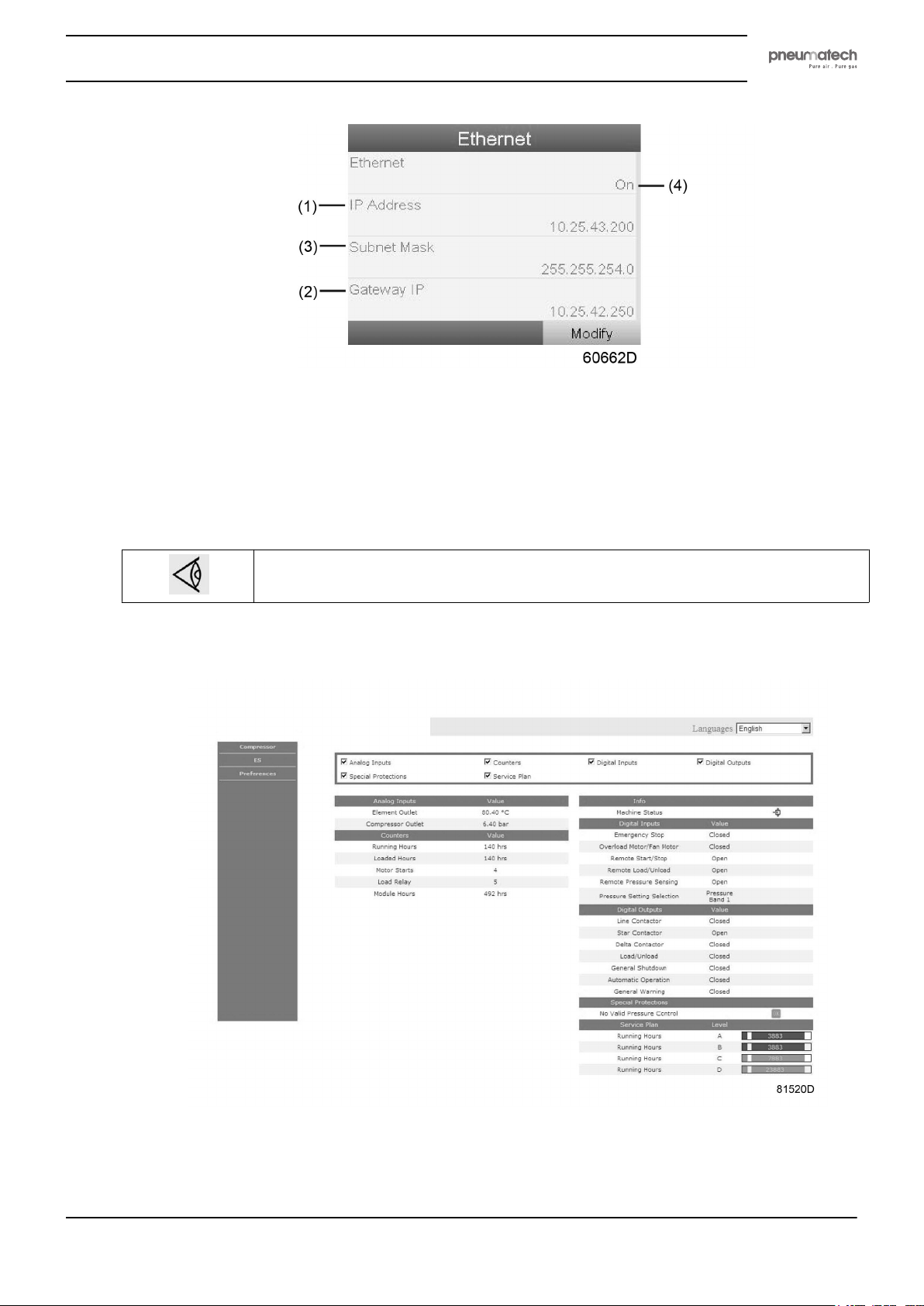
• Adapt IP Address (1)
• Adapt Gateway IP (2)
• Adapt Subnet Mask (3)
• Switch On (4) the Ethernet communication
38 2920 1891 00
Page 41
Instruction book
• Wait a few minutes so the LAN network can connect to the controller
Configuration of the web server
The internal web server is designed and tested for Microsoft® Internet Explorer.
Also "Opera", "Mozilla Firefox", "Safari"and "Chrome" should work.
Viewing the controller data
All screen shots are indicative. The number of displayed fields depends on the selected
options.
• Open your browser and type the IP address of the controller you want to view in your browser (in this
example http://192.168.100.100). The interface opens:
Screen shot (example!)
2920 1891 00 39
Page 42
Navigation and options
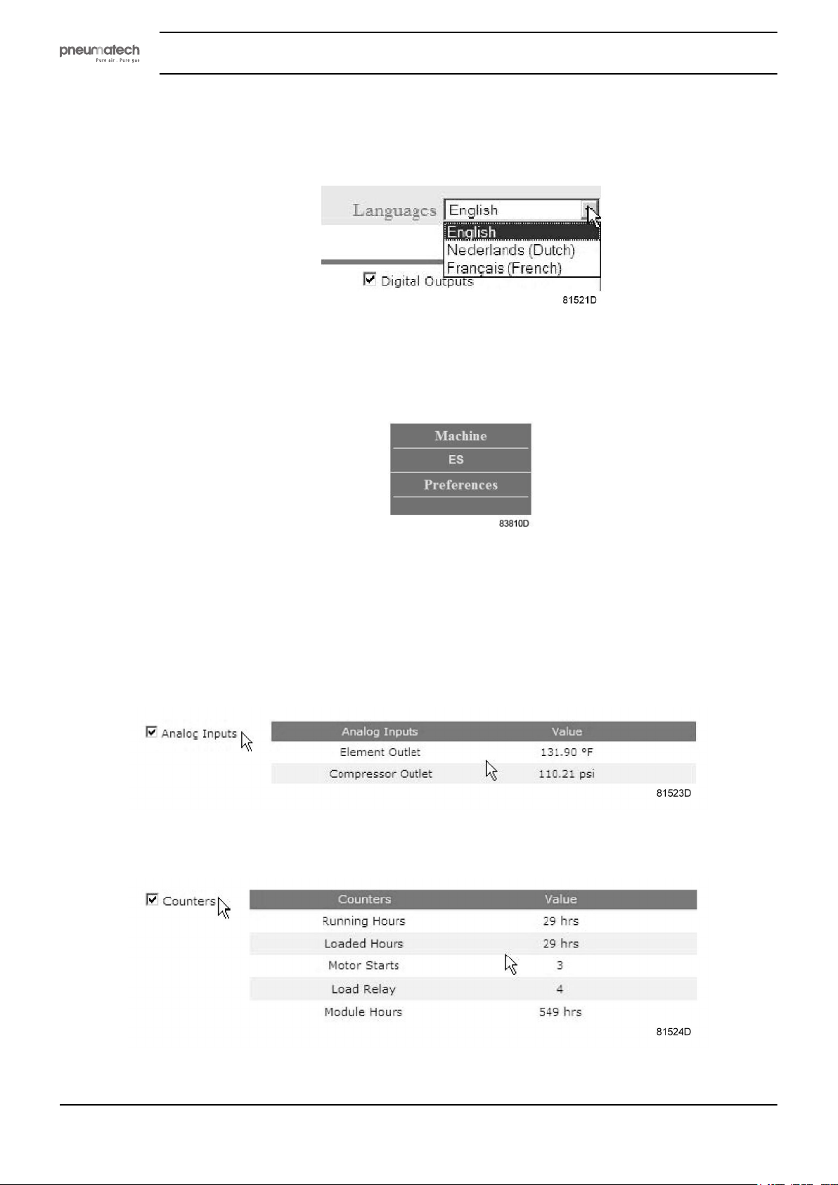
• The banner shows the unit type and the language selector. In this example, three languages are
available on the controller.
• On the left side of the interface, you can find the navigation menu.
If a license for ESi is foreseen, the menu contains 3 buttons.
• Machine: shows all generator settings.
• ES: shows the ESi status (if a license is provided).
• Preferences: allows to change temperature and pressure unit.
Instruction book
Unit settings
All unit settings can be displayed or hidden. Put a check mark in front of each point of interest and it will
be displayed. Only the machine status is fixed and can not be removed from the main screen.
Analog inputs
Lists all current analog input values. The measurement units can be changed in the preference button from
the navigation menu.
Counters
Lists all current counter values from controller and unit.
Info status
40 2920 1891 00
Page 43
Instruction book
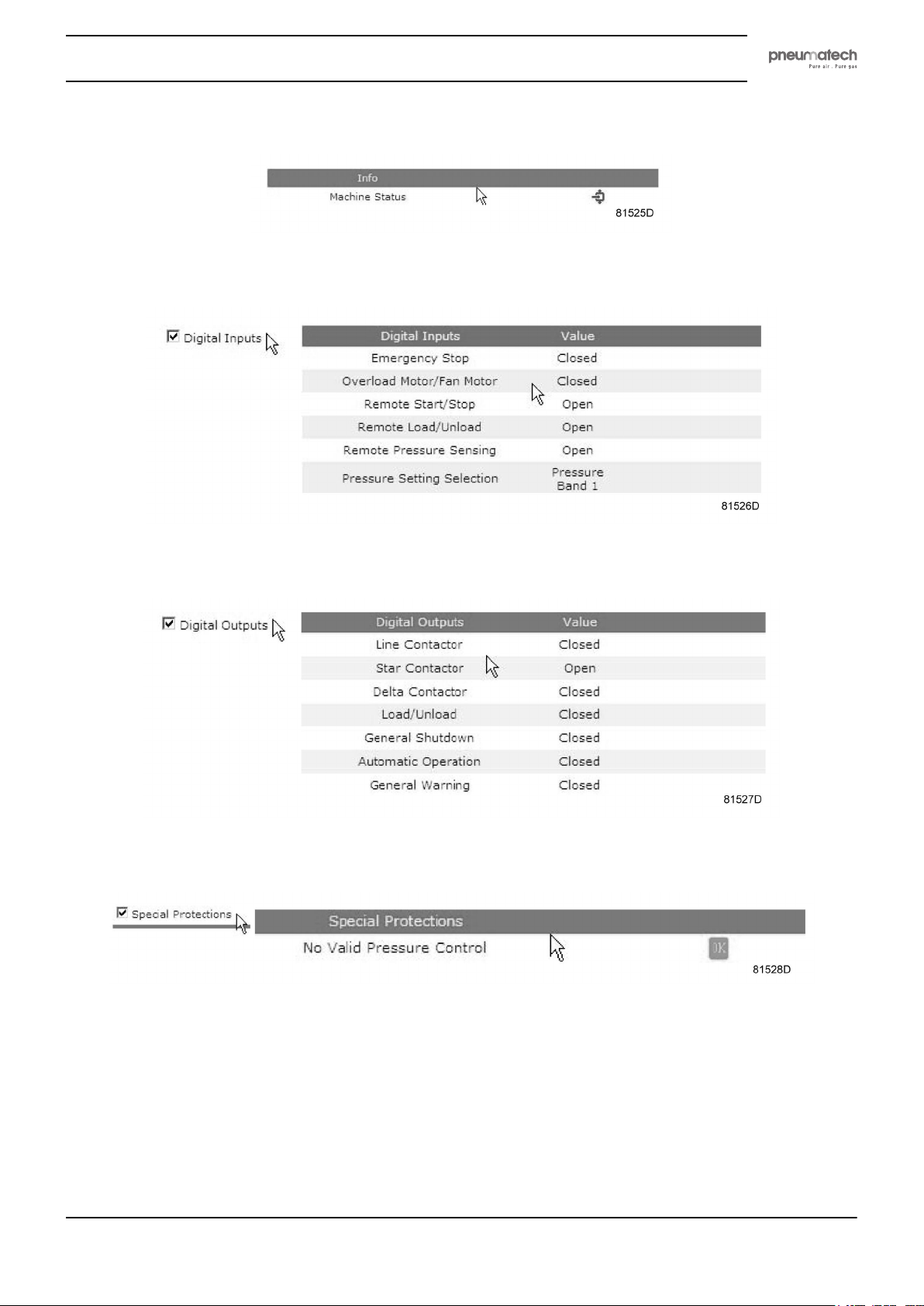
Machine status is always shown on the web interface.
Digital inputs
Lists all digital inputs and their status.
Digital outputs
Lists all digital outputs and their status.
Special protections
Lists all special protections of the unit.
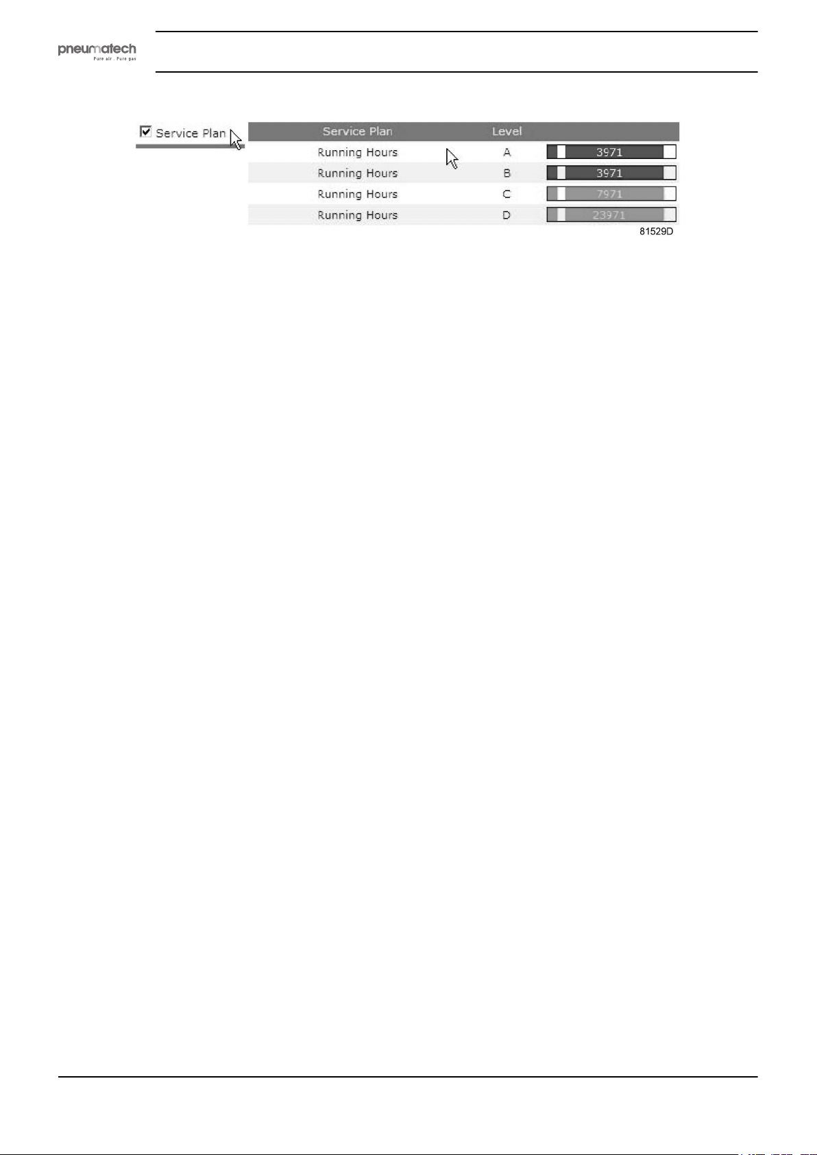
Service plan
Displays all levels of the service plan and their status. This screen shot underneath only shows the running
hours. It is also possible to show the current status of the service interval.
2920 1891 00 41
Page 44
4.9 Programmable settings
Description
The regulating and safety devices are factory-adjusted to obtain optimum performance of the dryer. No
adjustments are required.
Instruction book
42 2920 1891 00
Page 45
Instruction book
5 Installation
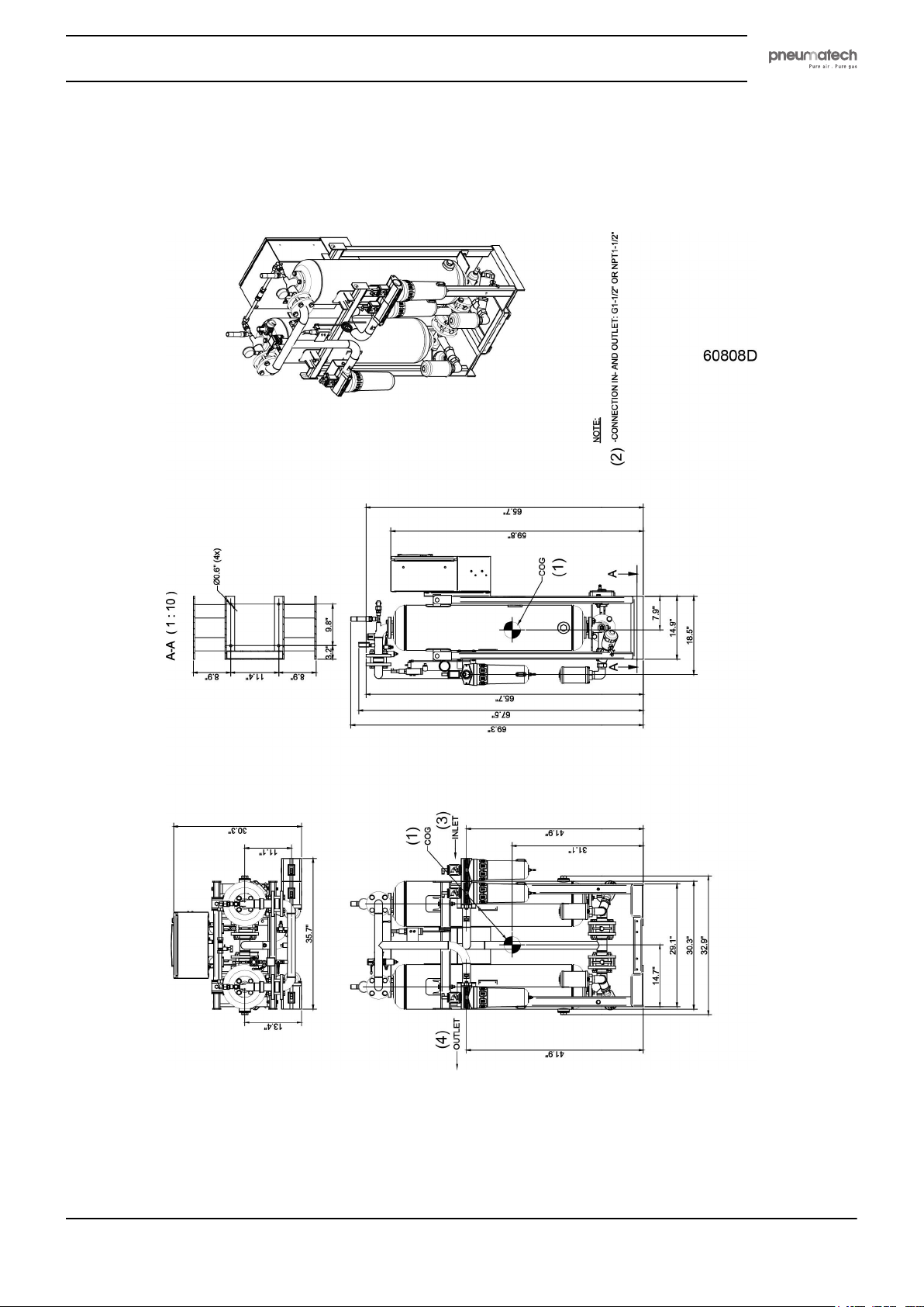
5.1 Dimension drawings
PH 230 HE (in inch)
2920 1891 00 43
Page 46
Instruction book
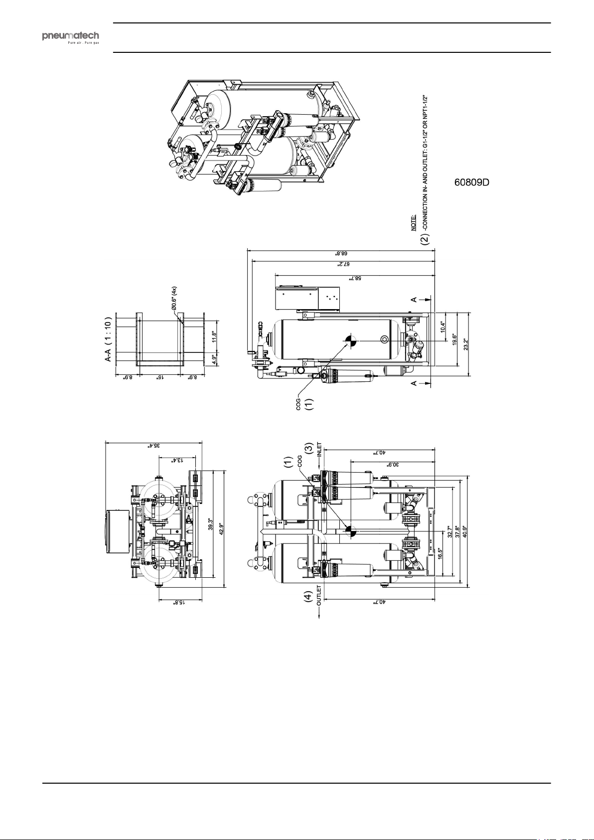
PH 320 HE (in inch)
44 2920 1891 00
Page 47
Instruction book
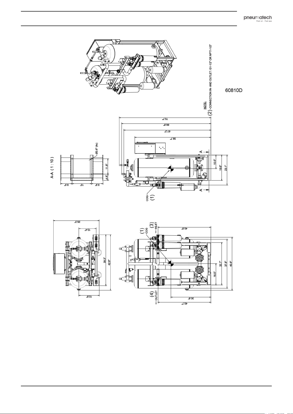
PH 390 HE (in inch)
2920 1891 00 45
Page 48
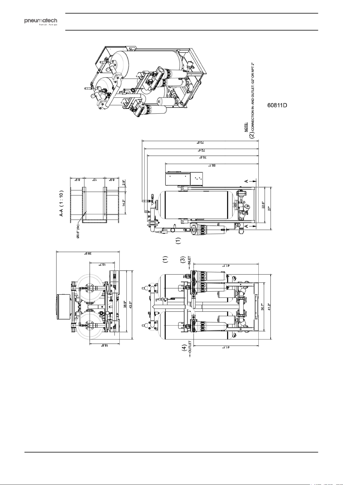
Instruction book
PH 530 HE (in inch)
46 2920 1891 00
Page 49
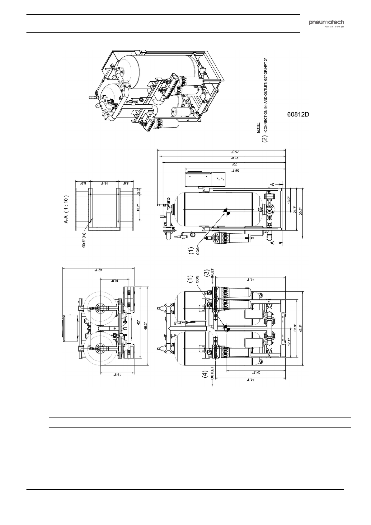
Instruction book
PH 635 HE (in inch)
(1) Center of gravity
(2) Dimension of inlet and outlet connection
(3) Dryer inlet
(4) Dryer outlet
2920 1891 00 47
Page 50
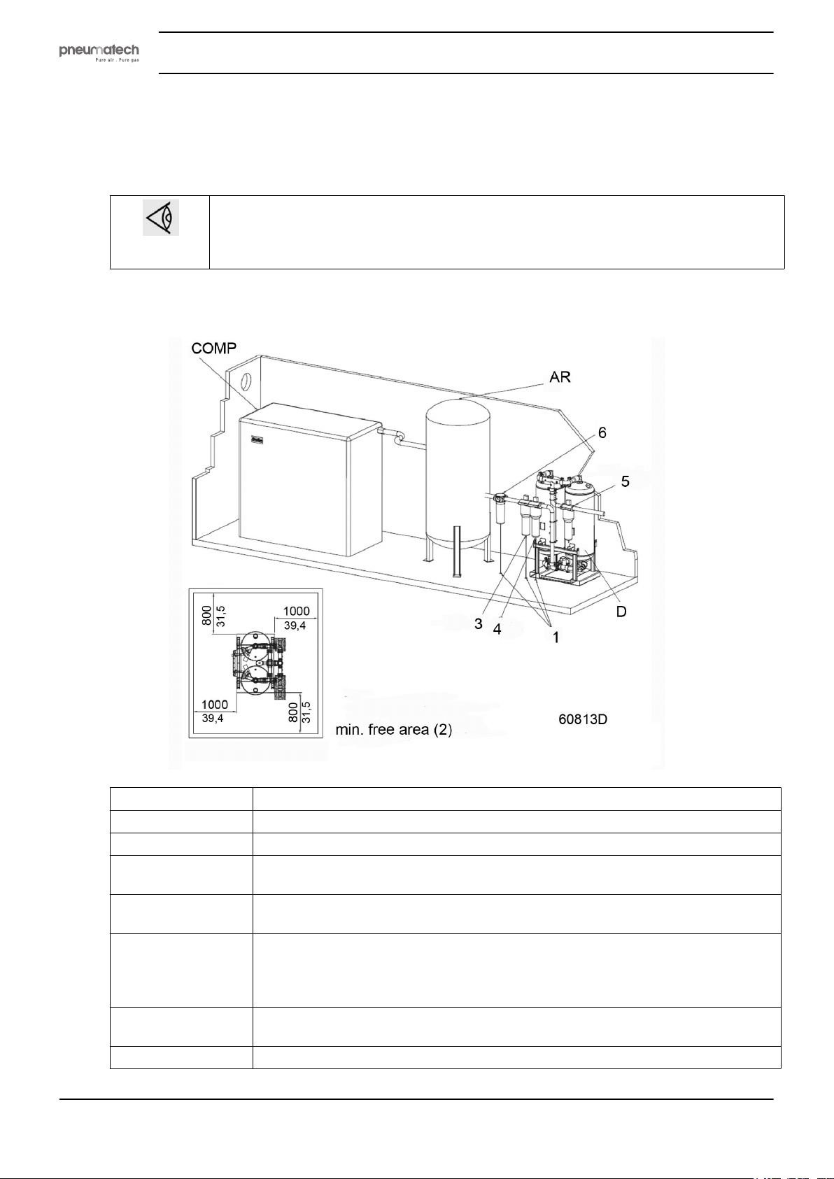
5.2 Installation proposal
Piping
Make sure that all pipes, filters, valves, etc. are clean and that they are installed correctly
with or without bypass system.
Make sure that the piping is installed stress-free. For more information concerning air nets,
cooling systems etc. refer to the compressor installation manual.
To ensure correct operation of the dryer, it has to be fitted properly into the compressed air circuit,
consisting of the compressor, the dryer and the application.
Instruction book
COMP Compressor
AR Air receiver
D Dryer
EIV External inlet valve (not shown)
To cut off the air supply towards the dryer
EOV External outlet valve (not shown)
To cut off the air supply towards the air consumer
BV Bypass valves (not shown on the drawings)
Together with the external inlet valve and the external outlet valve, the bypass
valves allow the dryer and the filters to be serviced while non-dried air flows through
the bypass system.
1 The drain pipes to the drain collector must not dip into the water. For draining of
pure condensate water, install an oil/water separator.
2 Minimum free area to be reserved for the dryer installation
48 2920 1891 00
Page 51

Instruction book
3 Compressed air prefilter for general purpose filtration, particle removal down to 1
4 High efficiency filter, particle removal down to 0.01 micron, maximum oil carry-over
5 Dust filter, particle removal down to 1 micron
6 Water separator (optional)
General recommendations
Keep the following in mind when installing the dryer:
• Place the dryer at a location where the temperature never exceeds the limits; see Technical Data.
• The dryer does not require extra ventilation.
• Fix the dryer as level as possible to the floor. Make sure the fixating bolts are tightened firmly and
that the floor is suitable for taking the weight of the dryer.
• Provide enough space around the unit to install and service the filter elements. A minimum free space
of 800 to 1000 mm (approx. 2.6 to 3.2 ft) is recommended - see the installation proposal drawings.
Provide sufficient space under the filter elements to be able to replace the filter cartridges without
having to disassemble the piping.
• Always install a high efficiency filter (4) at the inlet of the dryer. A prefilter (3) is recommended to
extend the lifetime of the high efficiency filter. The drain pipes (1) of the water separator and the
filters must not dip into the water. Use a dust filter (5) at the outlet of the dryer. Should oil vapor and
odors be undesirable, a carbon filter can be installed downstream the dust filter.
• If the compressor has no built-in water separator, a water separator (WSD) has to be installed before
the dryer in order to prevent free water from entering the dryer, as free water can damage the
desiccant. If the condensate contains oil, install an oil/water separator for draining of pure condensate
water.
• It is recommended to install bypass pipes with ball valves over the filters in order to isolate the filters
during service operations without disturbing the compressed air delivery.
• It is required to install pressure relief valves on each vessel of the dryer when ball valves are installed
at the inlet and the outlet of the dryer to isolate the dryer from the air net.
micron, maximum oil carry-over 0.5 ppm
This filter provides extra protection of the dryer and extends the lifetime of the high
efficiency filter cartridge (4).
0.01 ppm
To remove remaining impurities.
To remove dust particles originating from the desiccant.
To prevent free water from entering the dryer.
Never overload the dryer as a too high air speed will damage the desiccant. It may be
recommended to install the air dryer upstream of the air receiver to prevent overload (e.g.
after extending the dry air circuit). Consult your supplier if in doubt. See also section
Operating instructions for the correct operation procedure.
5.3 Electrical connections
The electrical wiring must comply with the local regulations. The air dryer must be earthed
and protected by fuses against short-circuiting.
2920 1891 00 49
Page 52

Instruction book
Connect the supply voltage to terminals 1X0 (L1 - L2) and 1X3 (earth). Install a power switch and fuses in
the supply line.
Maximum value fuse F1 and F2 is 10 A.
Reference Description
(1) Customer's installation
(2) Door
(3) Cubicle
Before switching on the main power supply, check the voltage requirements in the
technical specifications or on the dryer’s data plate.
50 2920 1891 00
Page 53
Instruction book
6 Operating instructions
Safety
Always observe all relevant safety instructions.
Initial start-up
To start up the dryer for the first time or after a long period of standstill, proceed as follows:
1. Open the bypass valves (if installed) of the dryer.
2. Close the air supply towards the PDP sensor (dryers with PDP sensor).
3. Close off the air supply from the compressor towards the dryer by closing the external
inlet valve (if
installed).
4. Close the
outlet valve (if installed).
5. Remove the silencers to prevent the silencers from getting clogged by the desiccant and wear a dust
mask, safety glasses and ear protection. (This is only required at initial start-up or after the desiccant
was replaced).
6. Start the compressor and wait for pressure.
7.
Slowly open the inlet valve.
8. Check the connections of the dryer for air leaks and remedy if necessary.
9. Switch the dryer on by pushing the Start button (14) on the Purelogic™ controller.
10. Let the dryer operate for several hours with the external outlet valve closed.
11. In case the silencers were removed, refit the silencers.
12. Gradually open the external outlet valve.
13. If applicable, close the bypass valves of the dryer.
14. Open the air supply towards the PDP sensor (dryers with PDP sensor).
If the application allows air that is not completely dry, the valve towards the dry air
consumer may be opened even before the optimal Pressure Dew Point (PDP) is
reached. In this case however, it will take more time for the desiccant to dry completely.
At initial start-up, and specially when the dryer is loaded from the beginning, it can take
a long time before the dew point is reached.
For a dew point of -100 ˚F, it can take up to more than 10 days before this value is
reached.
It is therefore recommended to operate the dryer for a number of days with the outlet
valve closed.
2920 1891 00 51
Page 54
Normal start
If the dryer has not been used for more than 3 months, refer to section Initial start-up. In all other cases,
proceed as follows:
Instruction book
1. Cut off the air supply from the compressor towards the dryer by closing the external
2. Close the air supply towards the PDP sensor (dryers with PDP sensor).
3. Close the external outlet valve (if installed) between the dryer and the dry air consumer.
4. Start the compressor and slowly open the external inlet valve.
5. Switch the dryer on by pushing the Start button (14) on the Purelogic™ controller.
6. Gradually open the air outlet valve.
7. If applicable, close the bypass valves of the dryer.
8. Open the air supply towards the PDP sensor (dryers with PDP sensor).
Close the external inlet valve in case the compressor needs to be restarted. The high
air speed in the start-up phase of the compressor may damage the desiccant.
To prevent this, a sonic nozzle (available as option) can be installed
Sonic nozzles
8092 2617 37 Sonic nozzle for PH 230 HE
8092 2617 45 Sonic nozzle for PH 320 HE
8092 2617 52 Sonic nozzle for PH 390 HE
8092 2617 60 Sonic nozzle for PH 530 HE
8092 2617 78 Sonic nozzle for PH 635 HE
inlet valve.
During operation
At regular intervals, check the status of the LED’s on the control panel. Refer to section Problem solving.
If the PDP Warning LED is lit and the application allows only dry air, shut down the application and let the
dryer regenerate first. Check the PDP temperature regularly. If the PDP temperature is too high, let the
dryer regenerate by closing the outlet valve.
Stopping
To stop the dryer, proceed as follows:
1. If installed and if necessary, open the bypass valves of the dryer so that the application will still
receive compressed air.
2. Close the external inlet valve between the compressor and the dryer and the external outlet valve
between the dryer and the dry air consumer.
3. Let the dryer operate for a period without consumption, to depressurize the vessels.
4. Stop the dryer by pushing the Stop button (13) on the Purelogic™ controller.
The LED’s for PDP warning and PDP alarm are only functional if the dryer is equipped
with a PDP sensor!
52 2920 1891 00
Page 55

Instruction book
If the dryer is stopped for a longer period, keep the external inlet and outlet valve
closed to avoid moisture from entering the dryer.
Under no circumstances must compressed air be allowed to flow through the dryer
when the electrical power is switched off (regeneration of the desiccant material will no
longer be possible).
2920 1891 00 53
Page 56
7 Maintenance
7.1 Maintenance
General recommendations and precautions
The dryer does not need any specific maintenance. Nevertheless, before carrying out any maintenance or
corrective activity, read the following recommendations and safety precautions and act accordingly:
Instruction book
• Stop the dryer by pushing the Stop button (13) on the Purelogic™ controller.
• Disconnect all pressure sources and vent the internal pressure of the system before dismantling any
pressurized component.
• Use Original Parts only. Consult the Spare Parts List for part numbers. For preventive maintenance,
dedicated service kits are available.
• Check for correct operation after maintenance.
Filters and valves installed between the compressor, the dryer and the air consumer
may need other maintenance activities than those mentioned below (e.g. draining the
filters and replacing the filter elements). Refer to the appropriate manual for more
information.
54 2920 1891 00
Page 57
Instruction book
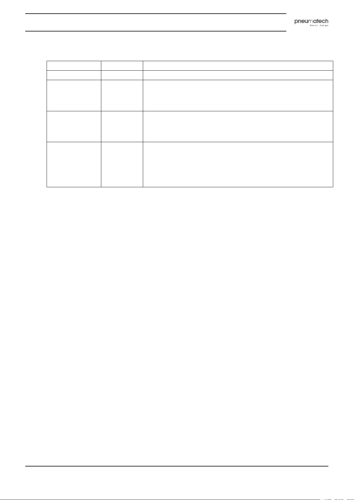
Preventive maintenance schedule
Frequency Service plan Activity
Daily Check the display panel for information and service messages.
Every 6 months or
every 4000 hours
of operation (1)
Every year or
every 8000 hours
of operation (1)
Every five years or
every 40000 hours
(1)
A • Check for damaged wiring or loose connections.
B • Service plan A
C • Service plan B
• Check for air leaks.
• Replace the in- and outlet filter cartridges.
• Replace the silencers.
• Exchange the dew point sensor. The certificate is valid only one
year. Contact the supplier of your equipment for re-calibration of
the PDP sensor.
• Replace desiccant
• Replace the inlet valves and revise the actuators
• Replace the check valves
Always replace all o-rings, seals and nylon washers that come free
when executing the scheduled maintenance.
(1) whichever comes first
In normal working conditions, the lifetime of the desiccant is approximately 5 years.
It is recommended to have the desiccant cartridges replaced by a qualified service technician, authorized by
the manufacturer.
Reset the service timer after a maintenance intervention.
All spare parts required for scheduled maintenance are included in specific service kits. Consult the spare
parts list for part number information.
7.2 Disposal of used material
Used filters or any other used material (e.g. desiccant, lubricants, cleaning rags, machine parts, etc.) must
be disposed of in an environmentally friendly and safe manner, and in line with the local recommendations
and environmental legislation.
Refer to local regulations for directions on how to dispose of electronic components in an environmentally
friendly manner.
2920 1891 00 55
Page 58
8 Problem solving
Overview
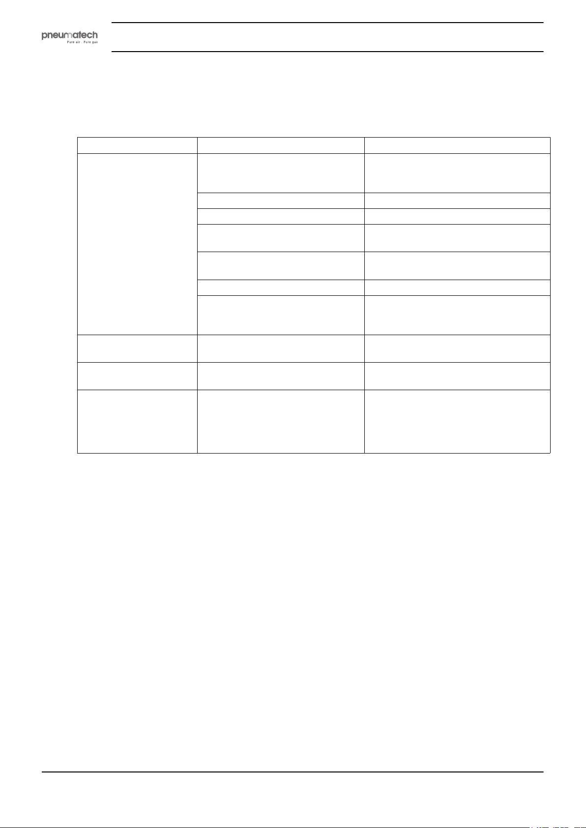
Symptom Possible cause Corrective action
PDP temperature too high The dryer has not had the time to
The dryer produces a lot
of noise.
Insufficient air leaves the
dryer.
LED Service warning /
Service alarm is alight.
Instruction book
Close the valve installed between the
regenerate completely.
The silencers are clogged. Replace the silencers.
The drain is not working correctly. Check the drain valve of the filter.
The air flow through the dryer is too
high.
The outlet pressure is too low. Check whether the compressor provides
The inlet temperature is too high. Check the compressor aftercooler.
Free water in the dryer. Check the water separator (WSD) and
Check the silencer and its fixation to
the unit.
Too much purge air escapes. Check the condition of the solenoid valve
Both LED’s are timer-controlled and
will light up after a certain time
(orange LED (warning) after 7750
hours, red LED (alarm) after 8000
hours).
dryer and the application (if permitted)
and have the desiccant regenerated.
Check for correct application.
enough air for the application.
the drain valve of the filters upstream of
the dryer.
Replace the silencer if necessary or
correct its fixation.
and replace it if necessary.
Contact your supplier for maintenance.
Reset the timer after maintenance.
56 2920 1891 00
Page 59
Instruction book
9 Technical data
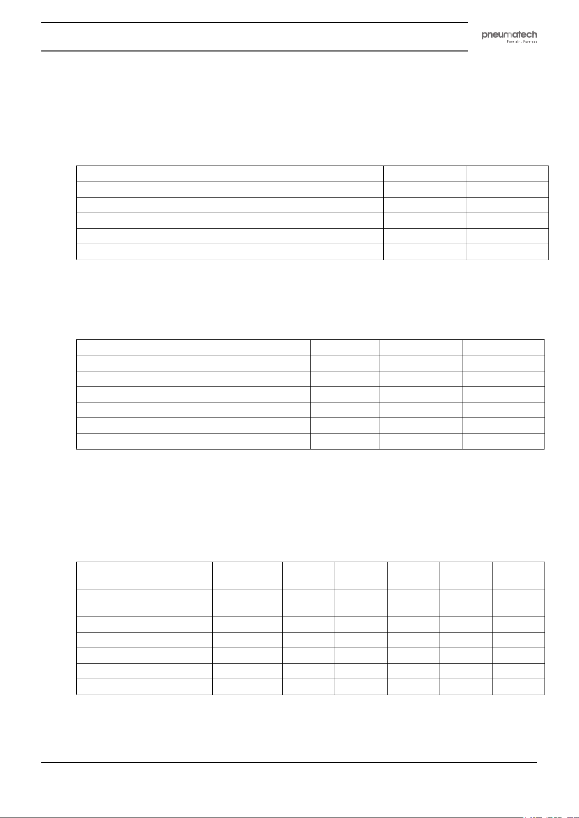
9.1 Reference conditions
Condition Unit 160 psi 210 psi
Effective inlet pressure of compressed air psi 101.5 181.3
Inlet temperature of compressed air ˚F 95 95
Relative humidity of the air at inlet % 100 100
Pressure dew point (PDP), standard version ˚F -40 -40
Pressure dew point (PDP), optional version ˚F -100 -100
9.2 Limitations for operation
Limitation Unit 160 psi 210 psi
Max. effective inlet pressure of compressed air psi 160 210
Min. effective inlet pressure of compressed air psi 58.0 160
Maximum ambient air temperature ˚F 104 104
Minimum ambient air temperature ˚F 35.6 35.6
Max. inlet temperature of compressed air ˚F 122 122
Min. inlet temperature of compressed air ˚F 35.6 35.6
9.3 Specific data
Standard version (PDP -40 ˚F) - 160 psi
Desiccant type: activated alumina (Al2O3)
PH 230
Max. volume flow at dryer
inlet
Total amount of desiccant lb 309 375 441 573 661
Mass lb 750 915 981 1223 1433
Time of half a cycle s 180 180 180 180 180
Regeneration time s 145 145 145 145 145
Installed power W 63 63 63 63 63
cfm 227 318 392 530 636
HE
PH 320
HE
PH 390
HE
PH 530
HE
PH 635
HE
2920 1891 00 57
Page 60
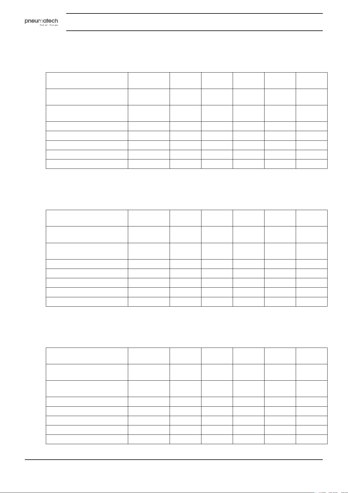
Standard version (PDP -40 ˚F) - 232 psi
Desiccant type: activated alumina (Al2O3 )
Instruction book
PH 230
Max. volume flow at dryer
inlet
Regeneration air consumption
average at max. inlet flow
Total amount of desiccant lb 309 375 441 573 661
Mass lb 750 915 981 1223 1433
Time of half a cycle s 250 250 250 250 250
Regeneration time s 195 195 195 195 195
Installed power W 63 63 63 63 63
cfm 271 381 466 636 763
% 15 15 15 15 15
Special version (PDP -100 ˚F) - 160 psi
Desiccant type: molecular sieves
PH 230
Max. volume flow at dryer
inlet
Regeneration air consumption
average at max. inlet flow
Total amount of desiccant lb 309 375 441 573 661
Mass lb 750 915 981 1323 1433
Time of half a cycle s 180 180 180 180 180
Regeneration time s 145 145 145 145 145
Installed power W 63 63 63 63 63
cfm 182 254 313 424 509
% 23 23 23 23 23
HE
HE
PH 320
HE
PH 320
HE
PH 390
HE
PH 390
HE
PH 530
HE
PH 530
HE
PH 635
HE
PH 635
HE
Special version (PDP -100 ˚F) - 232 psi
Desiccant type: molecular sieves
PH 230
HE
Max. volume flow at dryer
inlet
Regeneration air consumption
average at max. inlet flow
Total amount of desiccant lb 309 375 441 573 661
Mass lb 750 915 981 1323 1433
Time of half a cycle s 250 250 250 250 250
Regeneration time s 195 195 195 195 195
Installed power W 63 63 63 63 63
58 2920 1891 00
cfm 218 305 371 509 614
% 18 18 18 18 18
PH 320
HE
PH 390
HE
PH 530
HE
PH 635
HE
Page 61
Instruction book
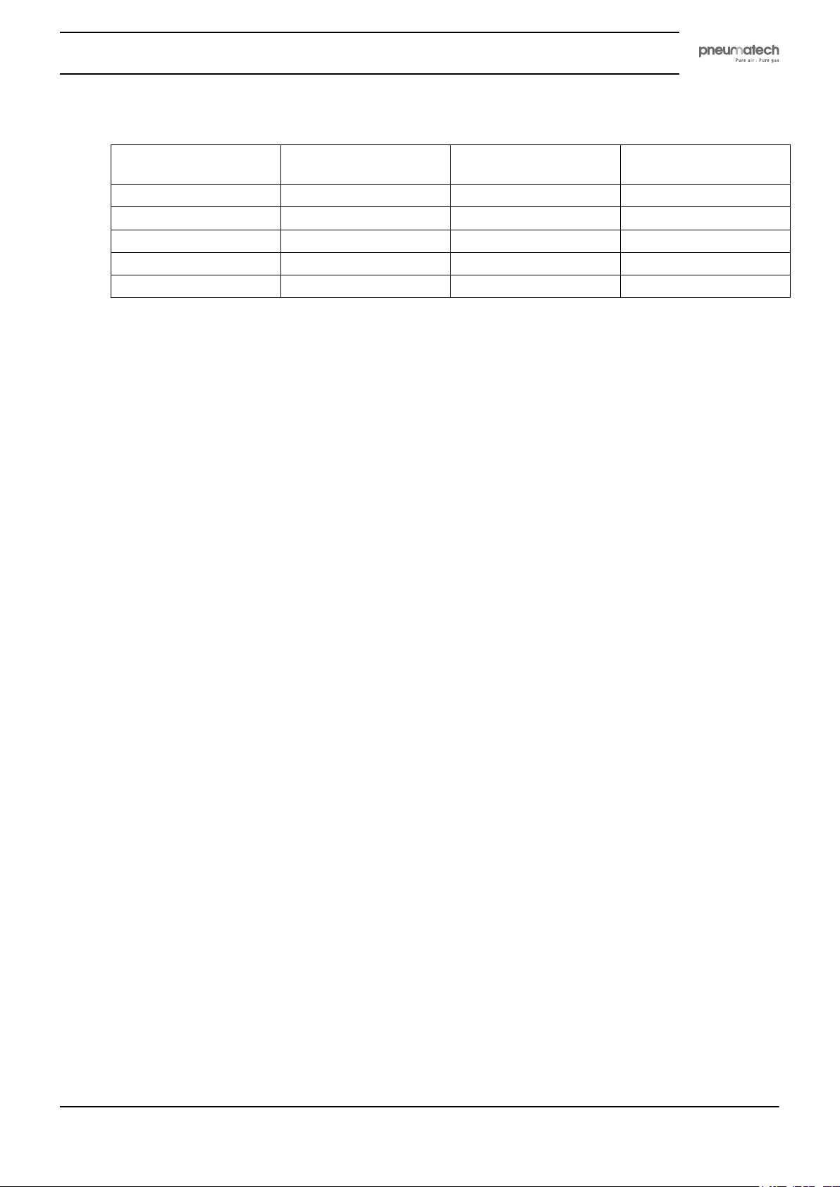
Recommended filter size
High efficiency
coalescing filter
PH 230 HE PF 6 C HE PF 6 S HE PF 6 G HE
PH 320 HE PF 7 C HE PF 7 S HE PF 7 G HE
PH 390 HE PF 8 C HE PF 8 S HE PF 8 G HE
PH 530 HE PF 9 C HE PF 9 S HE PF 9 G HE
PH 635 HE PF 9 C HE PF 9 S HE PF 9 G HE
Particulate filter General purpose
coalescing filter
2920 1891 00 59
Page 62
10 Instructions for Use
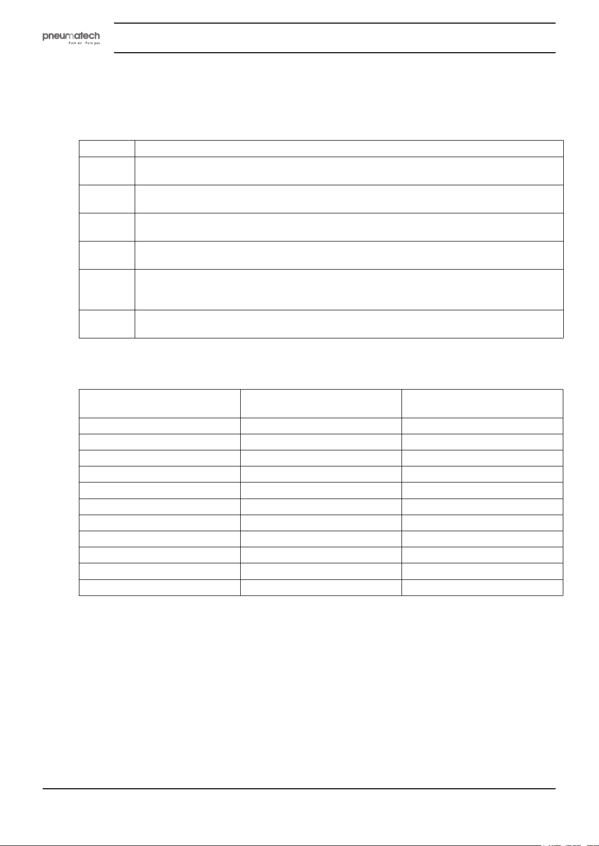
Instructions
Description
1 The dryers can contain pressurized air. This can be potentially dangerous if the equipment is
misused.
2 The dryer vessels must only be used as a compressed air vessel and must be operated within
the limits specified on the data plate.
3 No alterations must be made to the vessels by welding, drilling or other mechanical methods
without the written permission of the manufacturer.
4 The design pressure and temperature of this pressure bearing part must be clearly indicated
on the data plate.
5 If installed, the safety valve must correspond with pressure surges of 1.1 times the maximum
allowable operating pressure. This should guarantee that the pressure will not permanently
exceed the maximum allowable operating pressure of the vessel.
6 Original bolts have to be used after opening for inspection. The maximum torque has to be
taken into consideration (see table below).
Instruction book
Maximum bolt torque
Thread size Tightening torque
M3 1 0.3
M4 2.4 0.6
M5 5 1.2
M6 8 2.1
M8 20 5
M10 41 10
M12 73 18
M14 115 29
M16 185 46
M18 238 60
M20 335 84
(Nm)
Allowed deviation
(Nm)
60 2920 1891 00
Page 63

Instruction book
11 Guidelines for inspection
Guidelines
On the Declaration of Conformity / Declaration by the Manufacturer, the harmonized and/or other
standards that have been used for the design are shown and/or referred to.
The Declaration of Conformity / Declaration by the Manufacturer is part of the documentation that is
supplied with this air dryer.
Local legal requirements and/or use outside the limits and/or conditions as specified by the Manufacturer
may require other inspection periods.
2920 1891 00 61
Page 64

Page 65

Page 66
www.pneumatech.com
No. 2920 1891 00 / 2016 - 08 - Printed in Belgium
 Loading...