

Page 1
Users Guide: iMFD Sensor Mo dule
iMFD Sensor Module SM-Fluid Pressure
Version 1.0 March 14, 2008
*Please read the instructions completely through at least once before proceeding with the
installation to minimize errors.
*DO NOT use this sensor for Fuel Pressure sensing purpose
*Double check polarity of power before powering it on for the first time.
Overview:
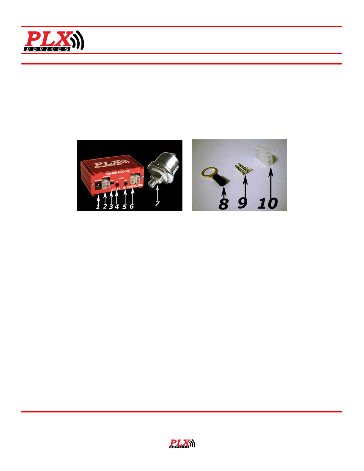
(Figure 1) (Figure 2)
1. Connects to 12V-18V power source.
2. Analog outputs (0-5V linear output) *For sensor #1 ONLY
3. Termination jumper. Closed for first SM in iMFD daisy chain.
4. Connects to next SM in iMFD daisy chain or to first DM
5. Connects to previous SM or unconnected if first SM in iMFD daisy chain
6. Connects to PLX Fluid Pressure Sensor. Up to 2 sensors can be connected for 2 channel operation.
7. Fluid Pressure Sensor (150psi). (*Using a sensor not provided by PLX Devices may lead to inaccurate readings due to a
mismatch in calibration)
8. 24k Gold Ring Terminal
9. Molex Connector Terminals
10. Molex 2 Pin Connector
Install the Fluid Pressure Sensor:
1. The PLX Fluid Pressure probe screws into a 1/8 NPT tap.
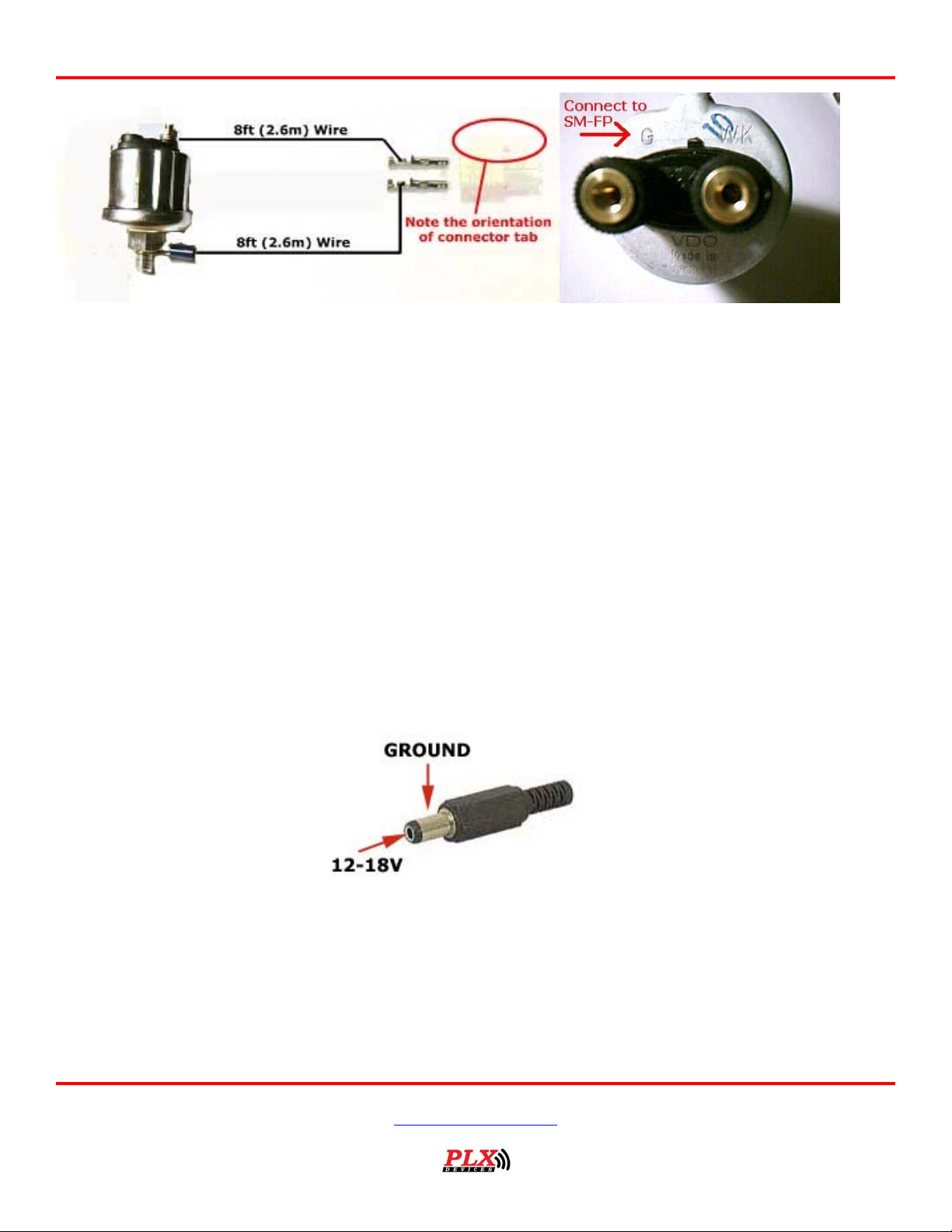
2. Connect the fluid pressure sensor with the provided 2 pin Molex connector according to the following diagram. It should
connect to the port “G” on the sensor. Connections can be made by crimping the terminals or soldering the terminals
with the provided wire. *Note the orientation of the Molex 2 pin connector. A reverse connection will result in inaccurate
readings and may damage the device.
Version 1.0 March 14, 2008
www.plxdevices.com
(408)745-7591
Page 2
Users Guide: iMFD Sensor Mo dule
(Figure 3a) (Figure 3b, Port “G”)
Connecting Power to the Unit:
CAUTION! CONNECTING THE SM-FluidPressure IN REVERSE
POLARITY WILL DAMAGE THE UNIT! CHECK CONNECTIONS BEFORE
POWERING ON.
1. The SM-FluidPressure accepts 12-18V DC for power. Connect the negative wire (black) to your vehicle’s ground. This is
usually the negative terminal of your automobile’s battery. Connect the positive wire (red) to your vehicle’s ignition power.
This power is only supplied when your key is turned passed a specific position and is off when your key is removed. Your
power connection must be capable of supplying at least 1 amp of current. A 5 Amp fuse is recommended for safety.
*If you plan to integrate the SM-FluidPressure with other aftermarket devices by utilizing the analog output signal wire. Make sure
that the negative wire (black) is connected as close as possible to your device's ground. This guarantees that both devices "see" the
same reference ground and a more accurate interpretation of the output voltages wil l be achieved. Please refer to the PLXApp notes
online for more information.
2. Locate the 2.1mm Power plug. Unscrew the plasti c cover and insert it into the red/black power wires.
3. Solder or crimp the red power wire to the CENTER of the connector. (12-18V)
4. Solder or crimp the black power wire to the SHIELD of the connector. (GROUND)
(Figure 4)
Using the Sensor Module in the iMFD Chain:
1.
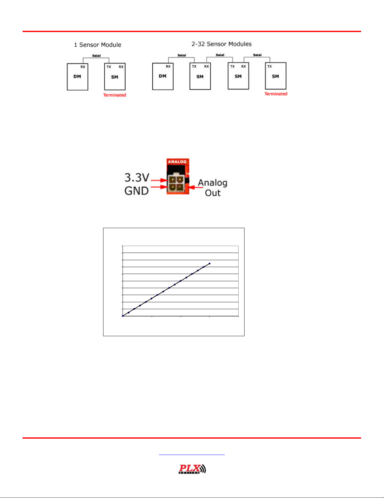
If the SM-FluidPressure is the o n ly sensor module or last sensor module in the iMFD chain, b e sure to have the termination
jumper installed. Otherwise, remove the jumper. Please refer to (Figure 1) for the location of the termination jumper.
Version 1.0 March 14, 2008
www.plxdevices.com
(408)745-7591
Page 3
Using the Sensor Module Analog Output:
1.
The SM-FluidPressure has one 0-5V analog output desig ned to be interfaced with a number of aftermarket products such as
engine management systems, data loggers and tuning electronics. It is n o t mandatory for you to use this outp ut for your
unit to properly function.
(Figure 6)
Users Guide: iMFD Sensor Mo dule
(Figure 5)
Linear Analog Output (0-5V)
Pressure Versus O ut put Vol t age
5.0
Voltage = 0.025 * Pressure ( PSI )
4.5
4.0
3.5
3.0
2.5
2.0
1.5
Output Voltage
1.0
0.5
0.0
0 50 100 150 200
Pressure PSI
Using the integrated fixed low pressure Warning Feature:
1.
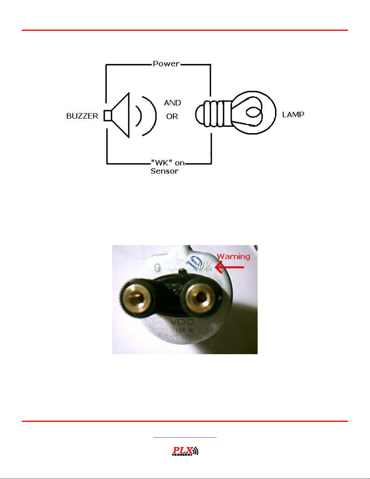
The SM-FluidPressure sensor itself has an integrated warning at 11.4psi. When the pressure is below and at 11.4 psi,
this integrated warning will be activated. The following illustration shows the connection using either a lamp of a b u z zer. If
using 12V as power source, make sure that the 12-16 V capable lamp or buzzer is used. If using a 3.3 v from analog port
provide from SM-FP, then please use a 3.3V capable lamp or buzzer. Some devices, however, can handle w ide ranges of
voltage inputs:
(Figure 7)
Sample Buzzer with 16v -5v power in capable: Mallory SONALERT II MSR516W
Version 1.0 March 14, 2008
www.plxdevices.com
(408)745-7591
Page 4
Users Guide: iMFD Sensor Mo dule
While the power input of the lamp and buzzer can be 12V or 3.3V, the ground side of the lamp or the buzzer needs to be
connected to the “WK” lead of the sensor.
(Figure 8, connection illustration of lamp or buzzer)
Caution: please follow the power input ratings indicated on the buzzer or the lamp to decide whether
using 12V or 3.3V power.
(Figure 9, location of “WK” lead for the grounding of lamp or buzzer)
Version 1.0 March 14, 2008
www.plxdevices.com
(408)745-7591
Page 5
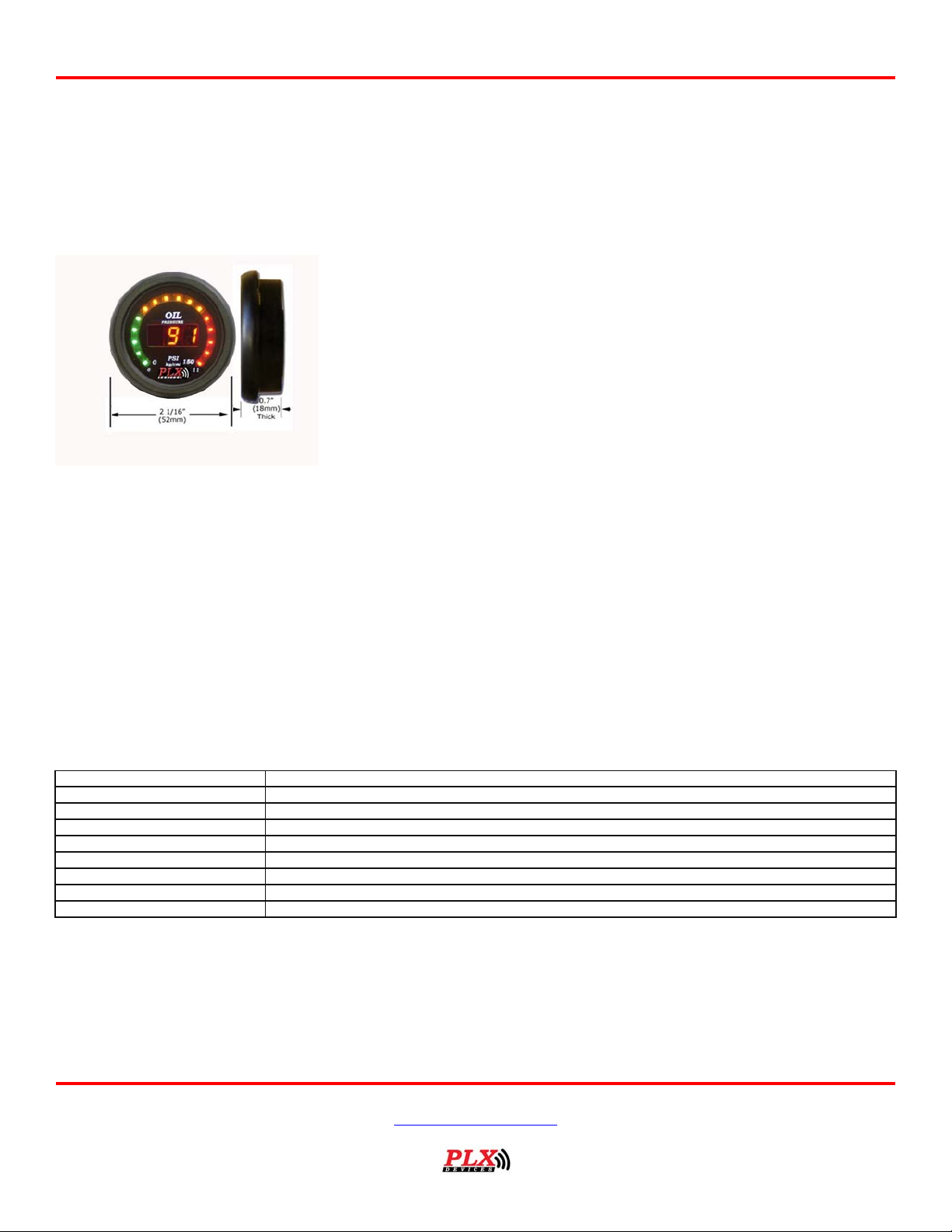
Recommended Accessory:
Users Guide: iMFD Sensor Mo dule
(Figure 10)
monitoring from your SM-FluidPressure. Release date will be updated.
DM-5 Fluid Pressure 52mm Gauge. Ideal for affordable Fluid Pressure
Included Items:
1. SM-FluidPressure main unit
2. 4ft red power wire
3. 4ft black ground wire
4. 4ft gray analog output wire
5. 2.1mm power connector
6. Resistive type fluid pressure sensor (Additional sensor
sold separately)
7. 24k gold ring terminal
8. 24k gold female disconnect terminal
9. 2 pin Molex connector with 2 terminals for sensor
10. 16ft sensor wire
11. 4 pin Molex connector with 4 terminals for analog output
12. 1ft Serial Cable
13. Termination jumper
14.
Specifications:
Physical Dimensions 2" x 2.875" x 1.125" (52mm x 75mm x 28mm) L x W x H
Accuracy ~1 PSI
Measurement Range 0-150 PSI
Analog Outputs Linear 0-5V (Driving Current 20mA)
Operating Voltage 8V-18V
Power Consumption 0.3 Watts
Operating Temperature 0 - 85 Deg C
Sensors Two Resistive Type Pressure Senders
Enclosure Extruded Aluminum
Quick start guide
TERMS OF USE
PLX Devices Inc. does not guarantee the Sensor Module functiona lity with any ECU, data logger or other devices that uses the output
signals. Implementation and integration of the Sensor Module with any other device(s) must be done at your own risk. Improper
installation and usage may lead to engine damage. Mount and install the Sensor Module in a location where it does not obstruct the
driver’s view and/or ability to safely control the vehicle.
Version 1.0 March 14, 2008
www.plxdevices.com
(408)745-7591
Page 6

Users Guide: iMFD Sensor Mod u le
LIMITED WARRANTY
PLX Devices Inc. warrants this product to be free from defects for 1 year from the date of purchase. If applicable, Oxygen sensors
and other non-serviceable items are excluded from stated warranty. Serviceable goods must be determined by PLX Devices to be
defective before any warranty or replacement is issued. PLX Devices’ obligation under warranty shall be limited to repairing or
replacing, under the discretion of PLX Devices, any part proven defective. This warranty is limited to the repair or replacement of
parts in the manufactured good and the necessary labor done to affect its repair or replacement.
SERVICE UNDER WARRANTY
In the unlikely event that your PLX Devices hardware should fail during the warranty period, a Return Material Authorization number
(RMA) must be first retrieved from PLX Devices Customer Support. Support can b e contacted through email:
or by phone: 408-745-7591. All serviceable goods must be packaged securely with proof of purchase, RMA number, with all shipping
charges prepaid and shipped to PLX Devices Inc. Goods returned under warranty must be received by PLX Devices Inc. within ten
(10) business days after the RMA number has been issued. Goods received after this period is subject to fees for the service of repair
or replacement. All repaired or replaced items shall be warranted for the rema ind er of the original product warranty.
RETURNS AND RESTOCKING FEE
A 15% restocking fee will apply to applicable PLX Devices products for refund. All returns are to be packed in original condition
including packaging, docume ntation, manuals, and accessor ies. Returns that do not include all t h e accessories and components ma y
be returned to the customer or charged on a per item basis. The customer assu mes responsibility for product until receipt at PLX
Devices Inc., shipping via an insurable carrier is recommended. Any unauthorized shipping charges will be billed to the customer or
shipment will be refuse d.
DISCLAIMER
PLX Devices Inc. shall not be lia ble for direct, special, in cidental, or consequential damages resulting from any legal theory including,
but not limited to, lost profits, downti me, goodwill, damage, injury to persons, or replacement of equipment and property due to
improper installation, integration and/or misuse of any PLX Devices Inc.’s product(s). This warranty app lies to the original purchaser
of product and is non-transferable. All implied warranties shall be limited in duration to the said 1 year warranty period.
Revision History
Version 1.0 (3/14/08) Initial release
Version 1.0 March 14, 2008
www.plxdevices.com
(408)745-7591
 Loading...