

Page 1
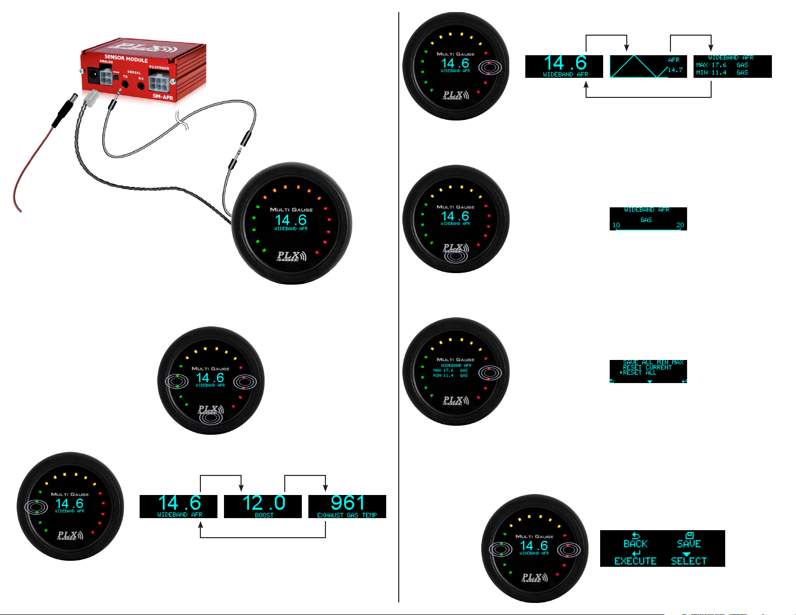
Setting up the DM-6 Multi Gauge to the SM-AFR
Navigating the DM-6
ere are a total of 3 capacitive touch buttons on the DM-6. ey are highlighted in the image below.
Use the right button to toggle between Numeric, Graph, and Peak/Hold
screen views.
Hold the logo button to display unit label and range. Le and right values
refer to entire LED sweep range.
In the Peak/Hold view, holding the right button will open a menu option
to save or reset current/all peak/hold values.
Use the le button to toggle between sensors.*
* - Sensors available are based on Sensor Modules in daisy chain. Display order is based on location of the Sensor Module in the daisy chain
e Menu
Pressing and holding both le and right buttons together will take you into the menu system. Once
inside the menu system, use the le button to save changes, the logo button to select which menu item is
currently selected, and the right button to access the current selection option. Please note the icons used.
Page 2
Setup Unit
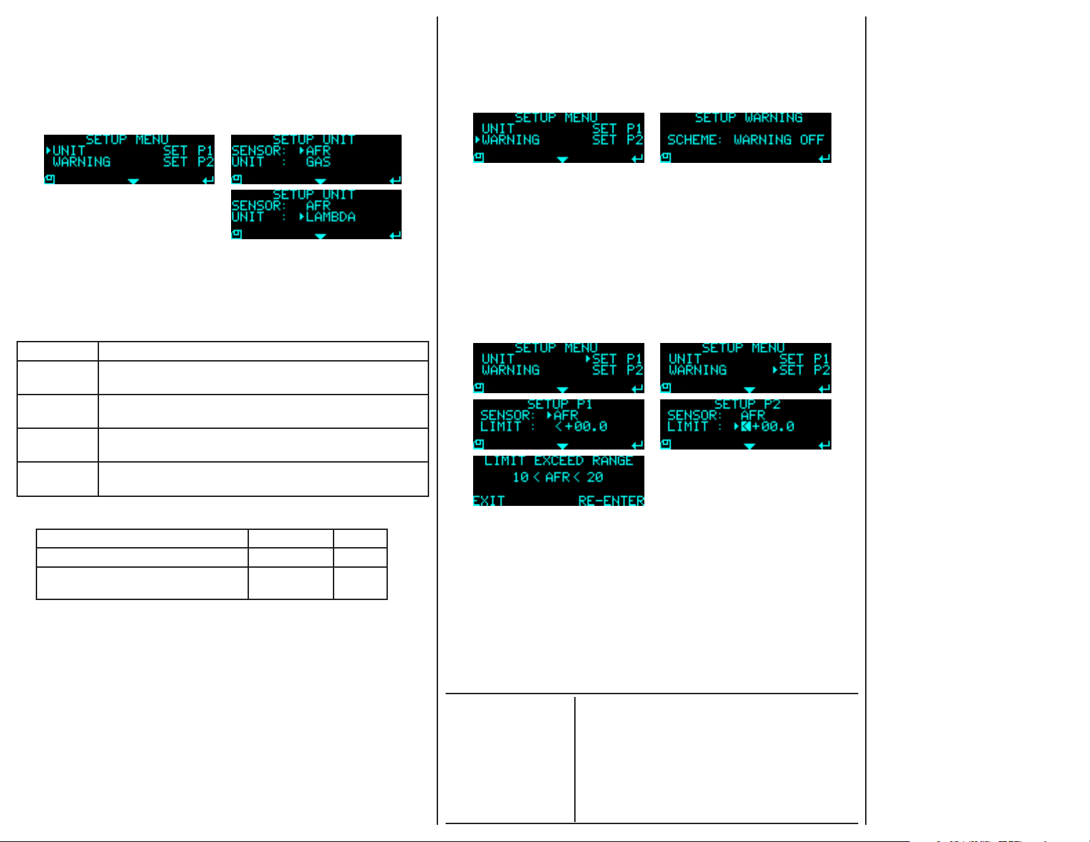
To setup the unit for a particular sensor, follow the procedures listed below:
1. Hold both le and right button to get into the “SETUP MENU”.
2. Press the right button to get into “SETUP UNIT” screen.
3. To change the sensor, press the right button.
4. To change the unit for that particular sensor, press the logo button to move down the arrow.
5. Press the right button to change the unit.
6. Press the le button to save and go back to the “SETUP MENU” screen.
Warnings:
e DM-6 can be operated to trigger the warning by setting the limit of the parameters
(Parameter 1(P1) and Parameter 2(P2)). Sensors that are daisy-chained with the DM-6 can
be selected to associate with the parameter setting. e DM-6 is capable of monitoring up to
2 parameters for warnings. To trigger the warning, the reading of the DM-6 must go above or
below the parameter setting as determined by the user. e table below shows the 4 schemes
that are supported by DM-6.
Mode Description
P1 and P2 Warning triggers only when the reading falls within the range set by
both Parameter 1 and Parameter 2
P1 or P2 Warning triggers only when the reading falls within the range set by
Parameter 1 or Parameter 2
P1 Only Warning triggers when the reading falls within the range set by
Parameter 1 only
P2 Only Warning triggers when the reading falls within the range set by
Parameter 2 only
Example:
Trigger point settings (SET P1 or SET P2) DM-6 Reading Result
Parameter 1: AFR > + 15.0 AFR = 14.0 FALSE
Parameter 2: EGT > + 800 EGT = 900 TRUE
If the DM-6 measures the above values and the “SCHEME” is set to “P1 OR P2”, this means
that if Parameter 1 is TRUE OR Parameter 2 is TRUE, the warning will trigger.
Since EGT is set in Parameter 2 and the measured value exceeds the trigger point set for this
particular sensor, the warning will trigger as soon as the measured value exceeds 800.
e LEDs will be ashing, indicating that the warning has been triggered. DM-6 will also
display the particular sensor that triggers the warning in the numerical mode.
If mode P1 AND P2 is selected, as the warning triggers, you can press the le button to view
the two sensors that trigger the warning.
To trigger the warning, rst set the “SCHEME”:
1. In the “SETUP MENU”, choose “WARNING” by pressing the logo button.
2. Press the right button to get into the “WARNING” screen.
3. To change the “SCHEME”, press the right button. Refer to the above table for the description for each “SCHEME”.
4. Press the le button to save and return to the “SETUP MENU” screen.
SET P1/SET P2:
1. In the “SETUP MENU”, choose “SET P1 or SET P2” by pressing the logo button.
2. Press the right button to get into the “SET P1 or SET P2” screen.
3. To select the sensor as the warning sensor, press the right button.
4. To set the trigger value, press the logo button to move down the arrow.
5. Press the right button to change the highlighted character.
6. To highlight the next character, hold on to the right button for 3 seconds.
7. Press the le button to save and return to the “SETUP MENU” screen.
8. If the limit is invalid, the “LIMIT EXCEED RANGE” screen will show to indicate the
proper range of values to be set.
9. Press the right button to re-enter the parameter or press the le button to go back to the
“SETUP MENU” screen.
Included Items:
1. DM-6 2 1/16” (52 mm) Gauge
2. 4 Pin connector for SM-AFR connectivity
3. 2 Terminals for 4 pin Connector
4. 3.5 mm Y Splitter
5. 6” M/F Extension Serial Cable
Specications:
Physical Dimensions:
Display Technology:
Power Consumption:
Number of Sensors:
Viewing Angle:
Polarization:
Supply Voltage:
Cable Length:
Operating Temp:
Human Interface:
Supported Units:
Standard 2 1/16 x 0.7” (52 X 18 mm)
1.10” OLED Screen (124 x 36 pixels), LED (16 Green, Yellow, Red)
180 Degrees
None
3.3 V and 8 V from SM Module
< 1 Watt
6’ Power, 6” Serial
0 - 85 Degrees Celsius
3 Button Capacitive Touch
16 Maximum Daisy Chain
US Standard, Metric
6. User guide
TERMS OF USE
PLX Devices Inc. does not guarantee product functionality
with any ECU, data logger or other devices that uses the
output signals. Implementation and integration of the PLX
products with any other device(s) must be done at your own
risk. Improper installation and usage may lead to engine
damage. Mount and install PLX products in a location
where it does not obstruct the driver’s view and/or ability or
safely control the vehicle.
PLX Devices Inc. does not guarantee product functionality
with ALL vehicles. Implementation and integration of the
PLX products with any other device(s) must be done at your
own risk. Improper installation and usage may lead to engine damage. Mount and install PLX products in a location
where it does not obstruct the driver’s view and/or ability or
safely control the vehicle
LIMITED WARRANTY
PLX Devices Inc. warrants this product to be free from
defects for 1 year from the date of purchase. If applicable,
Oxygen sensors and other non-serviceable items are
excluded from stated warranty. Serviceable goods must
be determined by PLX Devices to be defective before any
warranty or replacement is issued. PLX Devices’ obligation
under warranty shall be limited to repairing or replacing,
under the discretion of PLX Devices, any part proven defective. is warranty is limited to the repair or replacement
of parts in the manufactured good and the necessary labor
done to aect its repair or replacement.
SERVICE UNDER WARRANTY
In the unlikely event that your PLX Devices hardware
should fail during the warranty period, a Return Material
Authorization number (RMA) must be rst retrieved from
PLX Devices Customer Support. Support can be contacted
through e-mail: [email protected] or by phone: 408745-7591. All serviceable goods must be packaged securely
with proof of purchase, RMA number, with all shipping
charges prepaid and shipped to PLX Devices Inc. Goods
returned under warranty must be received by PLX Devices
Inc. within ten (10) business days aer the RMA number
has been issued. Goods received aer this period are subject
to fees for the service of repair or replacement. All repaired
or replaced items shall be warranted for the remainder of
the original product warranty.
RETURNS AND RESTOCKING FEE
All returns must be within 30 days of receipt. A 15%
restocking fee will apply to applicable PLX Devices products
for refund. All returns are to be packed in original condition including packaging, documentation, manuals, and accessories. Returns that do not include all the accessories and
components may be returned to the customer or charged
on a per item basis. e customer assumes responsibility
for product until receipt at PLX Devices Inc., shipping via
an insurable carrier is recommended. Any unauthorized
shipping charges will be billed to the customer or shipment
will be refused.
DISCLAIMER
PLX Devices Inc. shall not be liable for direct, special, incidental, or consequential damages resulting from any legal
theory including, but not limited to, lost prots, downtime,
goodwill, damage, injury to persons, or replacement of
equipment and property due to improper installation, integration and/or misuse of any PLX Devices Inc.’s product(s).
is warranty applies to the original purchaser of product
and is non-transferable. All implied warranties shall be
limited in duration to the said 1 year warranty period.
 Loading...