

Page 1

DM-100 OBDII Touch OLED Gauge
DM-100 OBDII Touch User Guide (V2.0) May 16, 2013
Users Guide: iMFD User Guide
A Silicon Valley California Company
DM-100 OBDII Touch Universal OLED
Multi-Gauge User Guide
This Product has Patents Pending
Designed by PLX Devices Inc. in Sunnyvale, CA
© PLX Devices 2013 All Rights Reserved
Version 2.0 May 16, 2013
www.plxdevices.com
(408)745-7591
Page 2

Users Guide: iMFD User Guide
2
Table of Contents
1 INTRODUCTION 5
1.1 Patents ................................................................................................................................................... 5
1.2 Warnings ............................................................................................................................................... 5
1.3 Key Features ....................................................................................................................................... 5
1.4 Package Contents ............................................................................................................................ 6
1.5 Software Requirements ............................................................................................................... 6
2 OVERVIEW 6
2.1 DM-100 OBDII Control Box ........................................................................................................ 6
2.2 Color OLED Gauge Head ............................................................................................................... 7
2.3 Touch Screen Interface ................................................................................................................ 7
2.4 Navigating the Menus ............................................................................................................................... 8
2.4.1 Gauges 8
2.4.2 OBDII Parameters 9
3 HARDWARE 9
3.1 Connecting Power ............................................................................................................................ 9
3.2 iMFD Daisy Chain ............................................................................................................................ 10
3.3 Programmable SM-OBDII ......................................................................................................... 11
3.3.1 Termination 11
3.3.2 Data Polling 12
3.3.3 Programming Sensors Modules 12
3.4 Setup Sensors .................................................................................................................................. 13
3.5 Special Note about the DM-100 OBDII Touch .............................................................. 13
4 STANDARD GAUGES 13
4.1 Analog Gauges (Graphical) ...................................................................................................... 13
Version 2.0 May 16, 2013
www.plxdevices.com
(408)745-7591
Page 3

Users Guide: iMFD User Guide
3
4.2 Digital Gauges (Numeric) ......................................................................................................... 14
4.3 Plot Gauges ........................................................................................................................................ 14
4.4 Peak and Hold .................................................................................................................................. 14
4.5 Two Parameter Gauges .............................................................................................................. 15
4.6 Four Parameter Gauges ............................................................................................................. 15
4.7 Custom Gauge .................................................................................................................................. 15
5 OBD II SENSORS 17
6 ENGINE CHECK 18
6.1 Viewing Trouble Codes ............................................................................................................... 18
6.2 Resetting Trouble Codes ............................................................................................................ 19
7 SETUP 19
7.1 Customizing Colors ....................................................................................................................... 19
7.2 Connect to PC ................................................................................................................................... 20
7.3 Warnings ............................................................................................................................................. 20
7.4 General Setup ................................................................................................................................... 21
7.4.1 Set Defaults 22
7.4.2 Boot State 22
7.4.3 OBD Diag 22
7.4.4 Boot Screen 22
7.5 The Color Palette ............................................................................................................................ 22
7.6 Wallpaper Backgrounds ............................................................................................................. 22
7.7 Sensor Table ..................................................................................................................................... 22
8 TECHNICAL SPECIFICATIONS 23
8.1 DM-100 OBDII Touch Control Box ....................................................................................... 23
8.2 DM-100 Display ............................................................................................................................... 23
Version 2.0 May 16, 2013
www.plxdevices.com
(408)745-7591
Page 4

Users Guide: iMFD User Guide
4
9 REVISION HISTORY 23
Version 2.0 May 16, 2013
www.plxdevices.com
(408)745-7591
Page 5

Users Guide: iMFD User Guide
5
1 Introduction
Thank you for purchasing the DM-100 OBDII Touch, the world’s most versatile gauge with plug and play
OBDII capabilities. The DM-100 OBDII Touch enables you to take advantage of the latest and cutting edge
technologies which are only employed in high end consumer electronics today. The Organic LED display
offers excellent color contrast and unsurpassed viewing angles that far exceed that of traditional LCD
displays. For your enjoyment, we’ve packed powerful features into the DM-100 OBDII Touch. Colors,
gauge styles and data can all be customized along with many additional features. We hope that you enjoy
our product as much as we enjoyed designing it.
1.1 Patents
PLX Devices Inc. currently has patents pending in the OLED display, user interface, digital logic
architecture, sensor detection circuitry, and customizable gauge implementation.
1.2 Warnings
To prevent fire or shock hazard, do not expose this product to rain or moisture.
Do not operate this product under direct sunlight or in high temperatures.
Damage and malfunction may occur.
Do not operate this product while driving. This may interfere with driving
operations, resulting in an accident.
Do not use this product and its accessories in any way other than specified by
PLX Devices. PLX Devices is not liable for accidents or damage cause by misuse
of this product.
Do not tamper, disassemble, or modify this product. This may cause an
accident, fire, electric shock, or product malfunction.
Do not operate this product without a protective fuse. (5-10 Amps)
1.3 Key Features
1) Plug and play OBDII 1996+ Vehicles
2) Daisy-chain up to 16 additional iMFD sensor modules
3) Built-in 4 programmable OBDII sensor modules
4) Color Organic LED technology (OLED)
5) 180 deg viewing angle
6) High contrast ratio
7) Multiple gauge styles (gauge, numeric, plot, 2 parameter, 4 parameter, custom)
Version 2.0 May 16, 2013
www.plxdevices.com
(408)745-7591
Page 6
Users Guide: iMFD User Guide
6
8) Peak and hold (high and low)
9) Intelligent warning (4 parameter comparison)
10) Custom gauge design
11) 4 point capacitive sense touch screen
12) Custom wallpaper upload
13) Automatic sensor detection
14) Extruded aluminum construction
1.4 Package Contents
1) DM-100 OBDII Touch Control Module
2) HDD-100 52mm OLED Display with touch screen
3) Power wire with 2.1mm connector and cigarette adapter
4) 1ft Serial Cable
5) 6ft USB Cable
6) Users Guide
1.5 Software Requirements
The DM-100 comes with PC software. The PC software allows you to do the following
1) Upload 8 Wallpapers (160 x 128 pixels) to the DM-100
2) Upload Custom Gauges (100 Frames) to the DM-100
3) Update DM-100 Sensor Table (If new sensors are available, sensor table must be updated)
Minimum System Requirements:
Windows XP or higher operating system
Pentium 4/Celeron 1GHz+
Athlon/Duron 1GHz+
512MB Ram
2 Overview
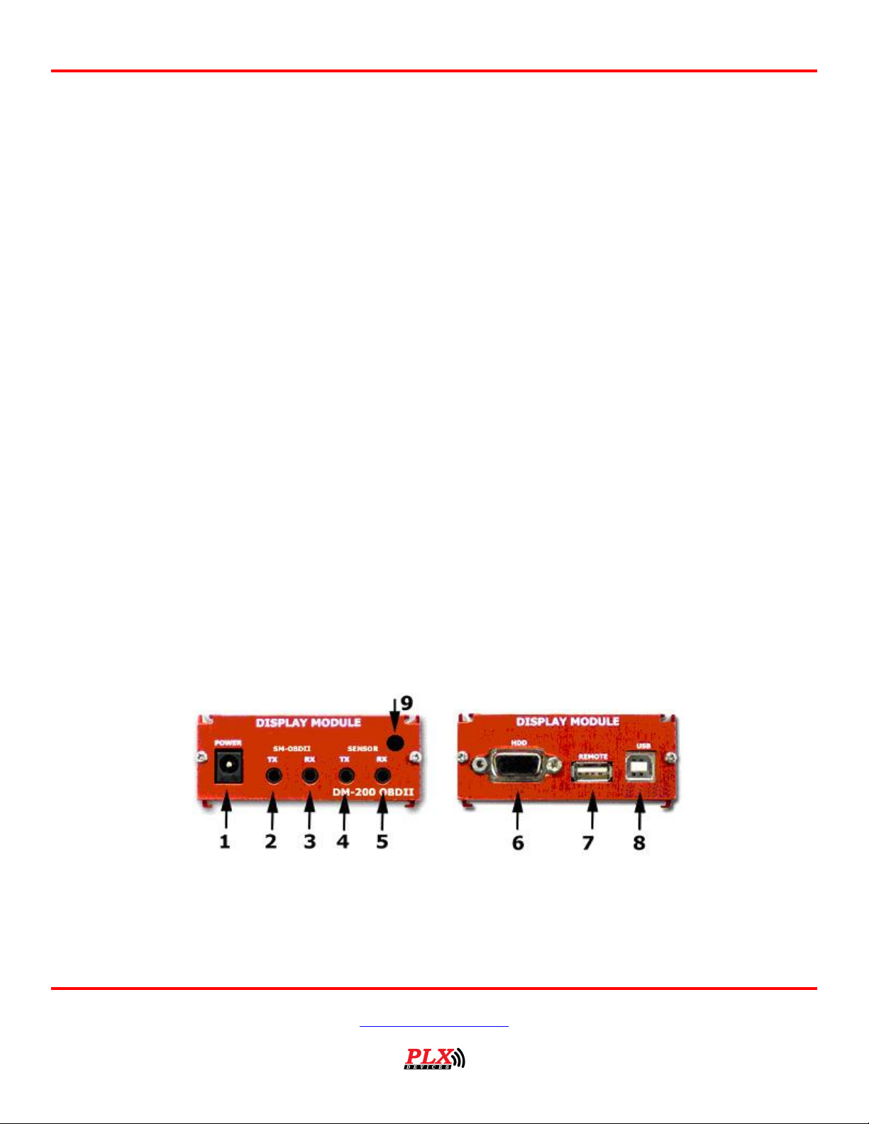
2.1 DM-100 OBDII Control Box
1) Connect to 12V-18V power source.
2) Output of SM-OBDII, Connect to additional Display Modules or loops back to sensor input (5)
3) Input of SM-OBDII, Connect from other sensor modules.
4) Connect to next Display Module(s) in chain
5) Connect to previous Display Module or last Sensor Module in chain
6) Connects to gauge head
Version 2.0 May 16, 2013
www.plxdevices.com
(408)745-7591
Page 7
7
7) Connect to touch screen interface on gauge head
8) Connect to USB port on PC for custom gauge, wallpaper, and sensor table upload
9) Connect to OBDII port in vehicle
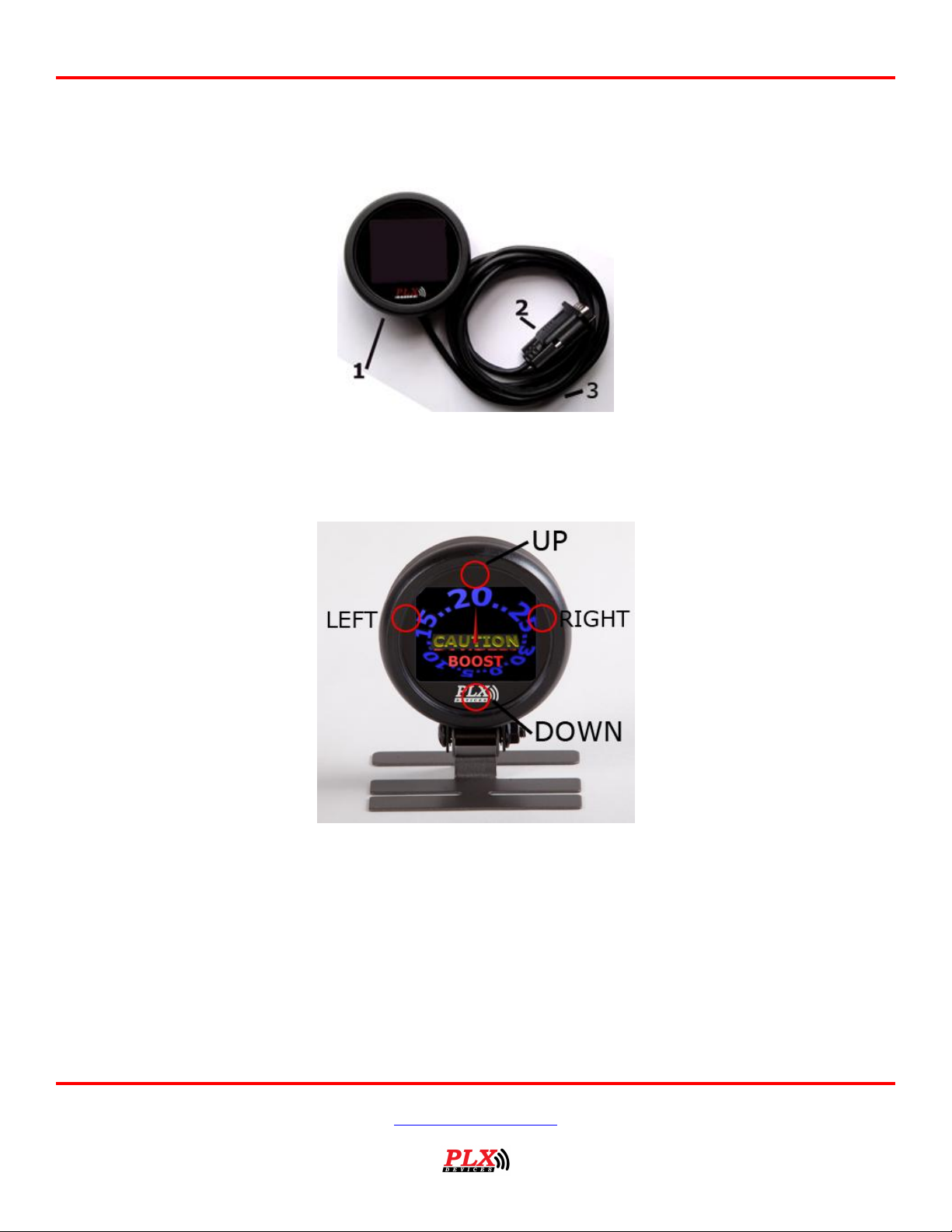
2.2 Color OLED Gauge Head
Users Guide: iMFD User Guide
1) 52mm (2 1/16”) OLED Display for DM-100
2) Connect to Control Box HDD port. (DO NOT CONNECT TO COMPUTER’s MONITOR OUTPUT!)
3) Connect to Control Box Remote port.
2.3 Touch Screen Interface
*Note RIGHT and LEFT touch screen locations are slightly above the center line of the gauge.
In Gauge Mode:
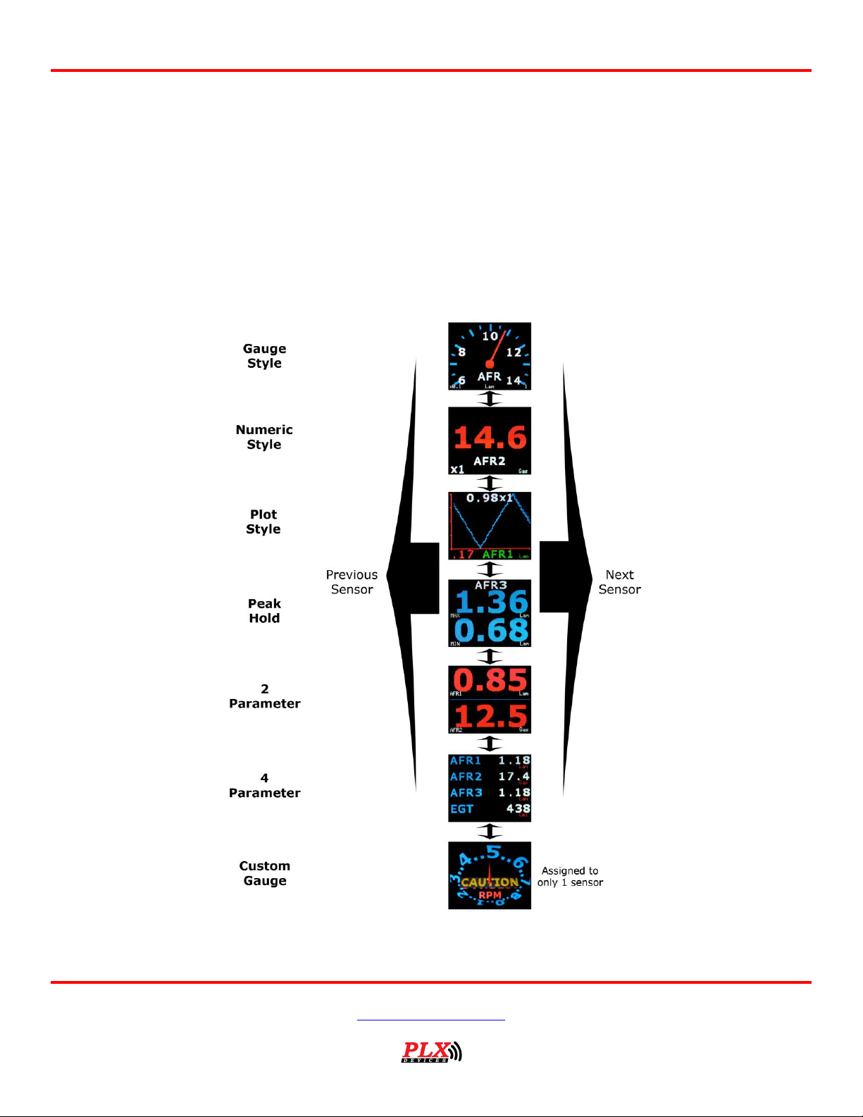
While the DM-100 is in Gauge Mode, touch Left – Right to switch between the gauge parameters
available. Touch Up – Down to switch between the type of gauge style you wish to view. Please refer to
section (2.4) for more details how to navigate the menu system.
Touch and hold both Left – Right for 3 seconds to enter into the setup menu.
OBDII Sensor Mode:
Version 2.0 May 16, 2013
www.plxdevices.com
(408)745-7591
Page 8
Users Guide: iMFD User Guide
8
While the DM-100 is in Sensor Mode, touch Left – Right to switch between pages. Please refer to section
(2.4) for more details how to navigate the menu system.
Setup Mode:
While in the DM-100 is in Setup Mode, follow the arrows on the screen to navigate and setup your gauge.
At any time, touch and hold both Left – Right for 3 seconds to enter and exit the setup menu.
2.4 Navigating the Menus
2.4.1 Gauges
Version 2.0 May 16, 2013
www.plxdevices.com
(408)745-7591
Page 9
Users Guide: iMFD User Guide
9
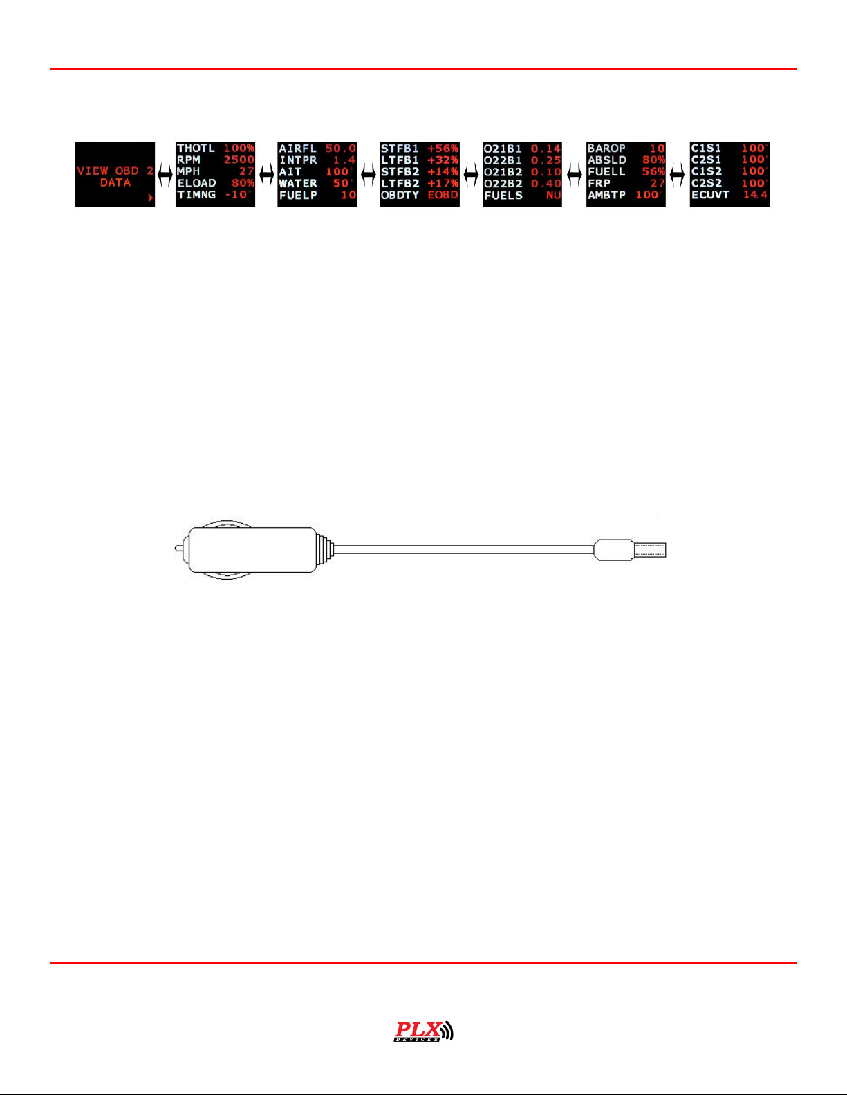
2.4.2 OBDII Parameters
3 Hardware
3.1 Connecting Power
Option 1: Using the Cigarette Lighter Power
This option is ideal if your cigarette lighter power is only ON when your ignition key is turned. In some
vehicles, your cigarette lighter power is always ON. Leaving your DM-100 OBDII unit always powered on
will drain your vehicle’s battery quickly. If this is the case for your vehicle, we recommend option 2.
Plug the 2.1mm power plug to the DM-100 control box where indicated ‘POWER.’ Plug the cigarette lighter
adapter connector into your cigarette lighter power plug in your vehicle.
Option 2: Hardwire your power connection
WARNING! CONNECTING THE DM-100 IN REVERSE POLARITY WILL
DAMAGE THE UNIT! CHECK CONNECTIONS BEFORE POWERING ON.
DAMAGE TO THE DM-100 WILL VOID YOUR WARRANTY.
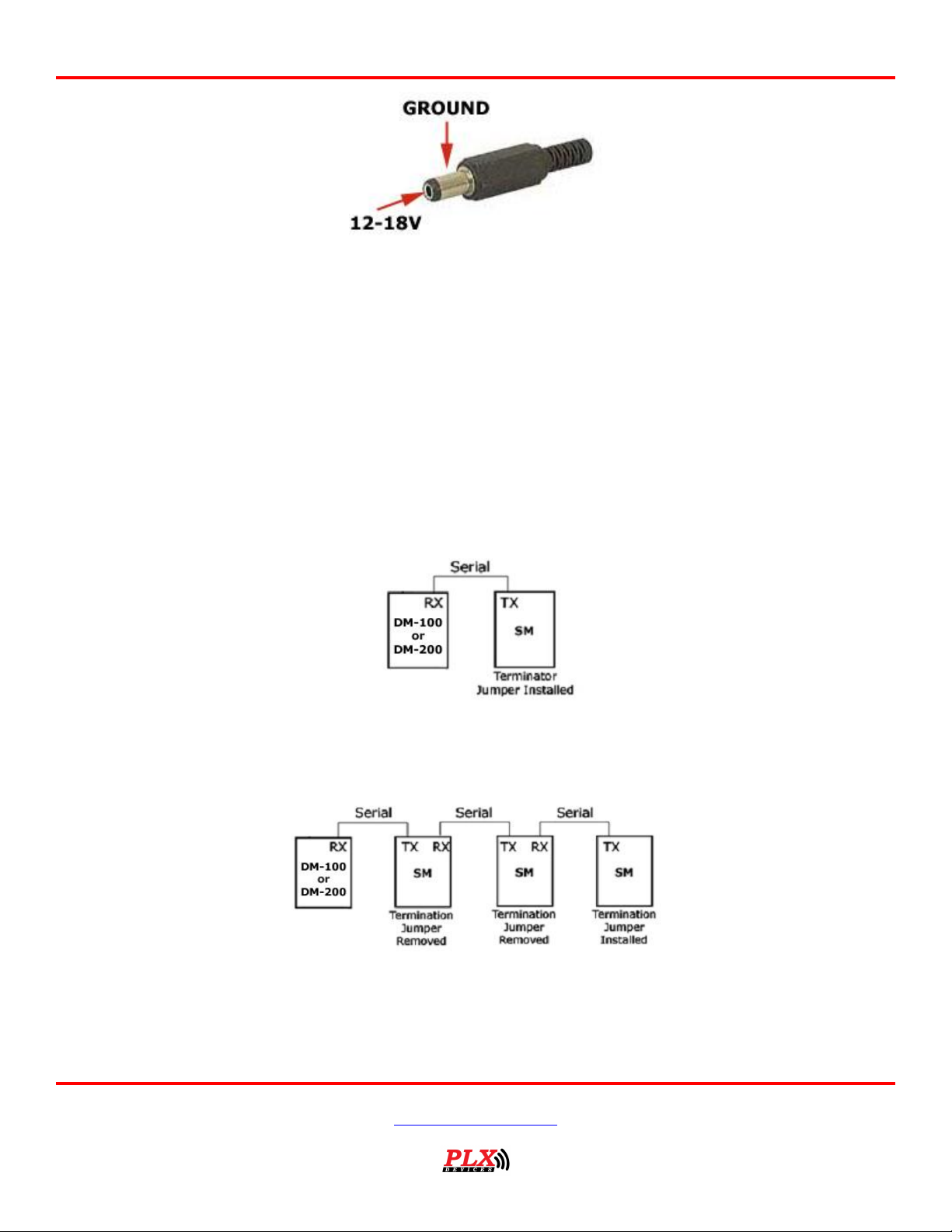
The DM-100 accepts 12-18V DC for power. Connect the negative wire (black) to your vehicle’s ground.
This is usually the negative terminal of your automobile’s battery. Connect the positive wire (red) to your
vehicle’s ignition power. This power is only supplied when your key is turned passed a specific position and
is off when your key is removed. Your power connection must be capable of supplying at least 1 amp of
current. A 5 Amp fuse is recommended for safety. Plug the 2.1mm power plug to the DM-100 main control
box where indicated ‘POWER.’
Version 2.0 May 16, 2013
www.plxdevices.com
(408)745-7591
Page 10
Users Guide: iMFD User Guide
10
The unit is working properly when the OLED screen turns on within 10 seconds. If your gauge does not
turn on, check your power connections and gauge connections.
3.2 iMFD Daisy Chain
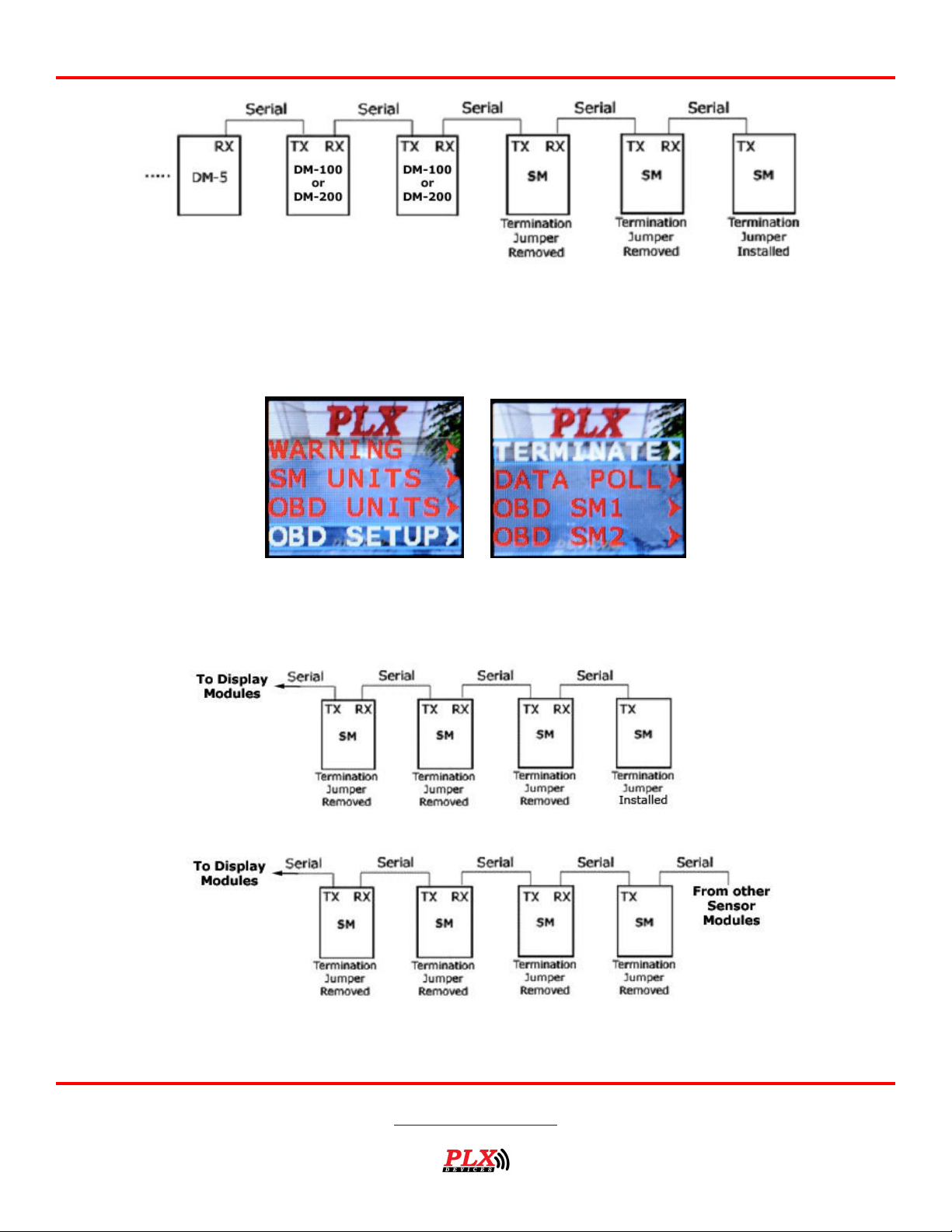
The iMFD architecture allows you to connect up to 16 Display Modules and 16 Sensors in a daisy chain
format. Please keep in mind that the DM-100 Touch has 4 SMs built-in. The 4 built-in SMs can be
programmed up to 26 different combinations. See section (3.3).
Basic Setup:
The most basic setup is to have one DM-100 and one Sensor Module connected in the iMFD chain. Make
sure that the sensor module has the termination jumper INSTALLED. Use the 1ft serial cable provided to
make the connection. Again please note that your DM-100 Touch Already has 4 built-in SMs.
Multiple Sensor Setup:
If you have more sensor modules, simply connect them in between the DM-100 and the Sensor Module.
Make sure that any subsequent sensor modules added to the iMFD daisy chain MUST have the termination
jumper REMOVED. Use the 1ft serial cable provided to make the connections.
If you have more Display Modules, such as the DM-100, DM-200, DM-6, DM-5 AFR, DM-5 EGT, and etc.
Simply connect them to the left of the DM-100/200 in the above diagram.
Version 2.0 May 16, 2013
www.plxdevices.com
(408)745-7591
Page 11
Users Guide: iMFD User Guide
11
3.3 Programmable SM-OBDII
Your DM-100 Touch includes two products in one. It combines a DM-100 and 4
programmable SM-OBDII modules into one product.
3.3.1 Termination
There are 2 options, Terminated and NOT Terminated. When the SM-OBD is terminated, it resembles the
following diagram
When the SM-OBD is NOT Terminated it resembles the following diagram.
Version 2.0 May 16, 2013
www.plxdevices.com
(408)745-7591
Page 12

Users Guide: iMFD User Guide
12
1) ABS THROTTLE (Absolute Throttle Position)
2) ENGINE RPM
3) VEHICLE SPEED
4) ENGINE LOAD
5) TIMING
6) INTAKE MAP (Manifold Absolute Pressure)
7) INTAKE MAF (Mass Air Flow Sensor)
8) STFUEL B1 (Short Term Fuel Trim Bank 1)
9) LTFUEL B1 (Long Term Fuel Trim Bank 1)
10) STFUEL B2 (Short Term Fuel Trim Bank 2)
11) LTFUEL B2 (Long Term Fuel Trim Bank 2)
12) AIR INT TEMP (Air Intake Temperature)
13) COOLANT TEMP
14) FUEL PRESSURE
15) O2VOLTAGE 1B1 (Narrowband O2 Sensor Voltage 1 Bank 1)
16) O2VOLTAGE 1B2 (Narrowband O2 Sensor Voltage 1 Bank 2)
17) O2VOLTAGE 2B1 (Narrowband O2 Sensor Voltage 2 Bank 1)
18) O2VOLTAGE 2B2 (Narrowband O2 Sensor Voltage 2 Bank 2)
19) FUEL LEVEL
20) CAT TEMP 1B1 (Catalytic Converter Temperature 1 Bank 1)
21) CAT TEMP 2B1 (Catalytic Converter Temperature 2 Bank 1)
22) CAT TEMP 1B2 (Catalytic Converter Temperature 1 Bank 2)
23) CAT TEMP 2B2 (Catalytic Converter Temperature 2 Bank 2)
24) ECU VOLTAGE
25) ABS ENG LOAD (Absolute Engine Load)
26) AMB AIR TEMP (Ambient Air Temperature) "AMB AIR TEMP");
3.3.2 Data Polling
Data Polling means that the SM-OBD ‘gets’ an updated value from the vehicle’s ECU (Engine Control Unit).
You can choose to turn ON or OFF Data Polling for Sensors 1,2,3,4. The more sensors you have set to
ON, the slower the refresh rate will be. It is recommended that you turn on data polling only on
sensors you wish to monitor, for maximum performance. By default, your unit comes preset with sensor
1,2,3,4 data polling ON.
For example, if you have your SM-OBDII set to:
Sensor1 = RPM
Sensor2 = Throttle Position
Sensor3 = Vehicle Speed
Sensor4 = Timing
And
Sensor1 Data Polling = ON
Sensor2 Data Polling = ON
Sensor3 Data Polling = ON
Sensor4 Data Polling = ON
RPM, Throttle Position, Vehicle Speed and Timing will all be monitored. However, the refresh rate of each
sensor is divided into 4. If you only wish to monitor RPM and nothing else, by setting
Sensor1 Data Polling = ON
Sensor2 Data Polling = OFF
Sensor3 Data Polling = OFF
Sensor4 Data Polling = OFF
Will lead to higher performance for sensor 1.
3.3.3 Programming Sensors Modules
Each sensor module can be programmed into any of the available OBDII sensors. Lists of the sensors are
below and can be programmed in the following setup menu. Keep in mind that your vehicle may not
support all the sensors listed below.
Version 2.0 May 16, 2013
www.plxdevices.com
(408)745-7591
Page 13
Users Guide: iMFD User Guide
13
3.4 Setup Sensors
Sensors are automatically detected when the gauge starts up. Detected sensors are arranged in the order
of the iMFD daisy chain connection. Up to 16 sensors can be detected and displayed on the DM-100 OBDII
Touch.
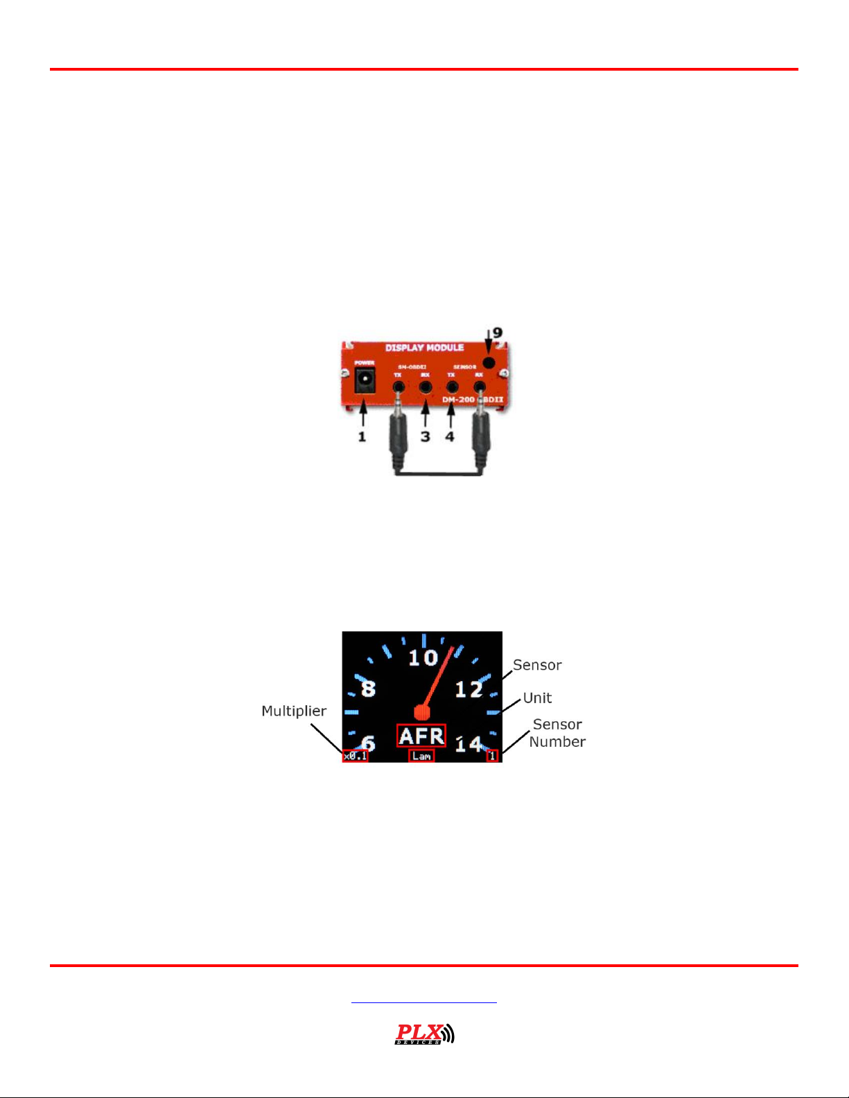
3.5 Special Note about the DM-100 OBDII Touch
If you wish to detect sensors from the SM-OBDII, you MUST connect the TX from the SM-OBD to the RX of
Sensors with the supplied 1ft serial cable. See diagram below. Be sure, you set the SM-OBDII to
TERMINATED. See section (3.3) for more information.
4 Standard Gauges
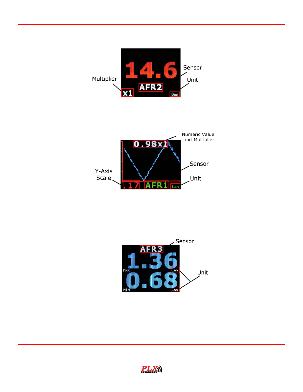
4.1 Analog Gauges (Graphical)
Analog gauges represent sensor data the same way a typical needle gauges does. Touch LEFT - RIGHT to
switch between sensors. Touch DOWN button to switch to digital gauges.
Version 2.0 May 16, 2013
www.plxdevices.com
(408)745-7591
Page 14
Users Guide: iMFD User Guide
14
4.2 Digital Gauges (Numeric)
Digital gauges represent sensor data in large numeric form. Touch LEFT – RIGHT to switch between
sensors. Touch DOWN to switch to plot gauges. Touch UP to switch to analog gauges.
4.3 Plot Gauges
Plot gauges represent sensor data in a real-time graphical form. The sensor data is plotted on the y-axis
and time is plotted on the x-axis. Touch LEFT – RIGHT to switch between sensors. Touch DOWN to switch
to peak-hold. Touch UP to switch to numeric gauges.
4.4 Peak and Hold
The DM-100 can detect both minimum and maximum values. The peak and hold function works in any
gauge mode, and you are not limited to having to remain on this screen for the DM-100 to memorize the
peak values. Touch LEFT – RIGHT to switch between sensors. Touch DOWN to switch to 2 parameter view.
Touch UP to switch to plot gauges.
Version 2.0 May 16, 2013
www.plxdevices.com
(408)745-7591
Page 15
Users Guide: iMFD User Guide
15
4.5 Two Parameter Gauges
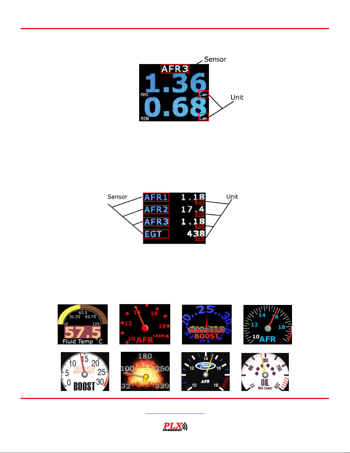
2 parameter gauges represent sensor data by showing 2 sensors simultaneously on the same screen.
Touch LEFT – RIGHT to switch between sensors. Touch DOWN to switch to 4 parameter view. Touch UP to
switch to peak and hold gauges.
4.6 Four Parameter Gauges
4 parameter gauges represent sensor data by showing all 4 parameters simultaneously on the same
screen. Touch LEFT – RIGHT to switch between sensors. Touch DOWN to switch to custom gauge view.
Touch UP to switch to 2 parameter gauges.
4.7 Custom Gauge
Version 2.0 May 16, 2013
www.plxdevices.com
(408)745-7591
Page 16

Users Guide: iMFD User Guide
16
For standard users:
Please visit our online custom gauge database located here
http://plxdevices.com/customgauges/
You will need to install the USB device drivers and the DM-100/200 Utility before you can upload your
custom gauge. The files are located here
http://plxdevices.com/product_info.php?id=MULTDM100TOUCH
For advanced users:
This option is not recommended unless you have experience with graphic design.
Steps to creating and uploading your own custom gauge:
1. Set the custom gauge to your desired sensor from the setup menu.
2. Determine the measurement range for 0
3. Design your gauge
4. Upload your design to the DM-100
The DM-100 gives you the capability of designing your own gauge from the PC and uploading it to the DM-
100. You can do this in Photoshop or any other image processing software you have. You will need 100
images or “frames” of (160 x 128 pixels) in JPG, BMP, TIFF or GIF format. Each
image corresponds to a specific measured value to your custom gauge parameter. For example, if your
custom gauge is set to WAT (water temperature from the SM-FluidTemp) with the units set to “Cel”
(Celsius). Toggle to the corresponding analog gauge to determine your minimum and maximum range.
Notice that on the bottom left of the above analog gauge reads 0 and the bottom right reads 16 (160 Deg
because of the x10). This tells you the minimum and maximum range of your custom gauge. Custom
gauges simply displays the corresponding “frame” or image which is associated to the measured value in
the analog gauge.
0th frame = 0 Deg C
1st frame = 1.6 Deg C
2nd frame = 3.2 Deg C
.
.
.
98th frame = 158.4 Deg C
99th frame = 160 Deg C
When you create your 100 images, make sure you create your 0th frame to depict a reading of 0 Deg C,
your 1st frame to depict a reading of 1.6 Deg C, your 2nd frame to depict a reading of 3.2 Deg C and so on
until your 99th frame depicts a reading of 160 Deg C.
When you name the files on your PC, it is suggested you name them in the according fashion.
YourFilename000.jpg
YourFilename001.jpg
th
frame through the 99th frame
Version 2.0 May 16, 2013
www.plxdevices.com
(408)745-7591
Page 17
Users Guide: iMFD User Guide
17
Sensor
Standard Units
Metric Units
Throttle Position
%
%
Engine Speed
rev/min
rev/min
Vehicle Speed
MPH
KMH
Engine Load
%
%
Engine Timing
Degrees
Degrees
Sensor
Standard Units
Metric Units
Air Flow Rate (MAF)
LBS/min
grams/sec
Intake Pressure (MAP)
inHG
Kpa
Air Intake Temperature
Fahrenheit
Celsius
Water Temperature
Fahrenheit
Celsius
Fuel Pressure
PSI
Kpa
Sensor
Standard Units
Metric Units
Short Term Fuel Trim Bank1
% % Long Term Fuel Trim Bank1
% % Short Term Fuel Trim Bank2
% % Long Term Fuel Trim Bank2
%
%
OBD Type
Type
Type
Sensor
Standard Units
Metric Units
Narrowband O2 Sensor Voltage Sensor 1 Bank 1
Volts
Volts
YourFilename002.jpg
.
.
.
YourFilename098.jpg
YourFilename099.jpg
Once you’ve successfully made or obtained your 100 frames, you will need to use DM-100 Utility PC
software (available from the PLX website) to upload your custom gauge to the DM-100. You can do this by
connecting the DM-100 to your PC with the supplied USB cable. The DM-100 must be powered on and
toggled to the setup mode “Connect to PC” for successful uploading to occur. Please refer to the DM100/200 Programmer users guide included on the CD for details how to upload your design.
You will need to install the USB device driver (available from the PLX website) for Windows to properly
detect the DM-100.
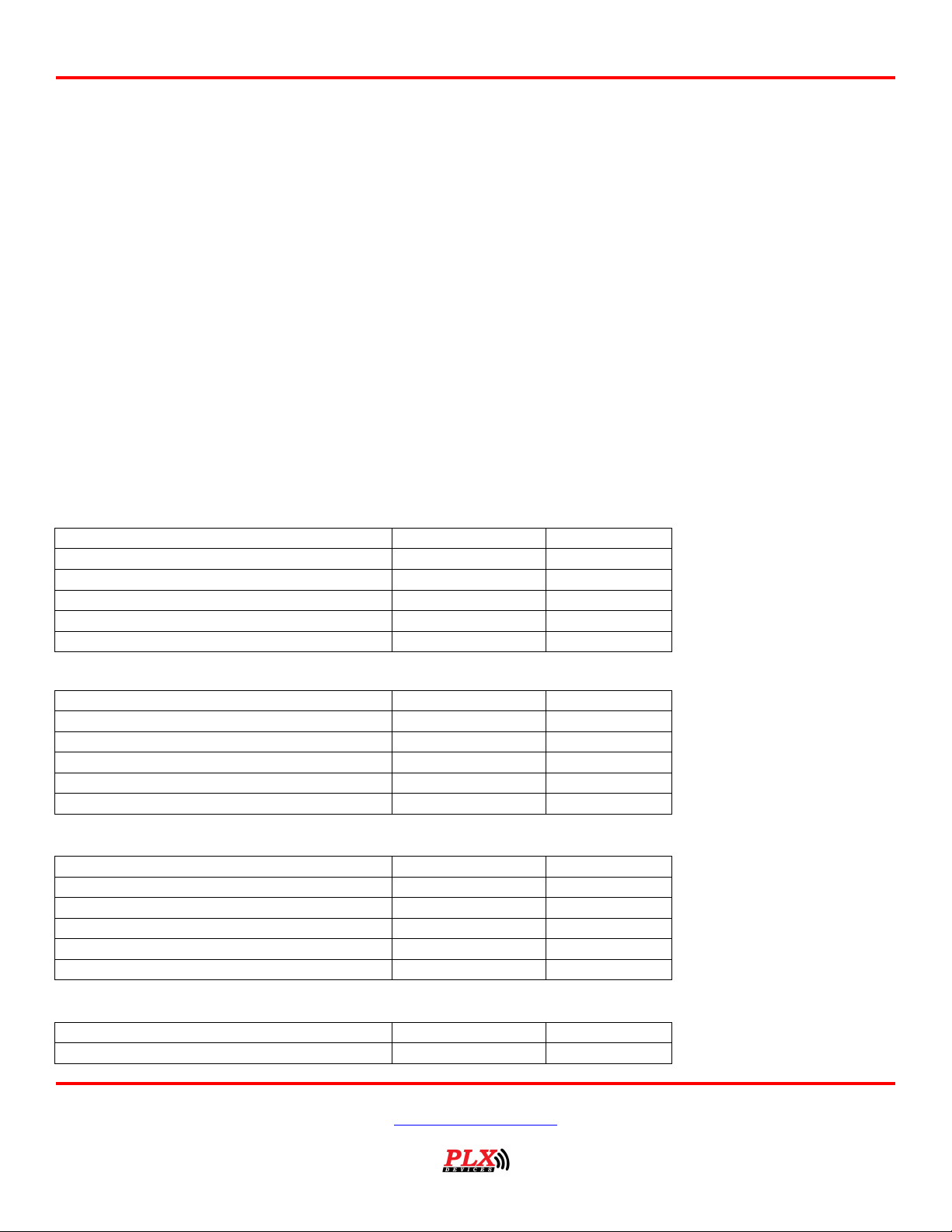
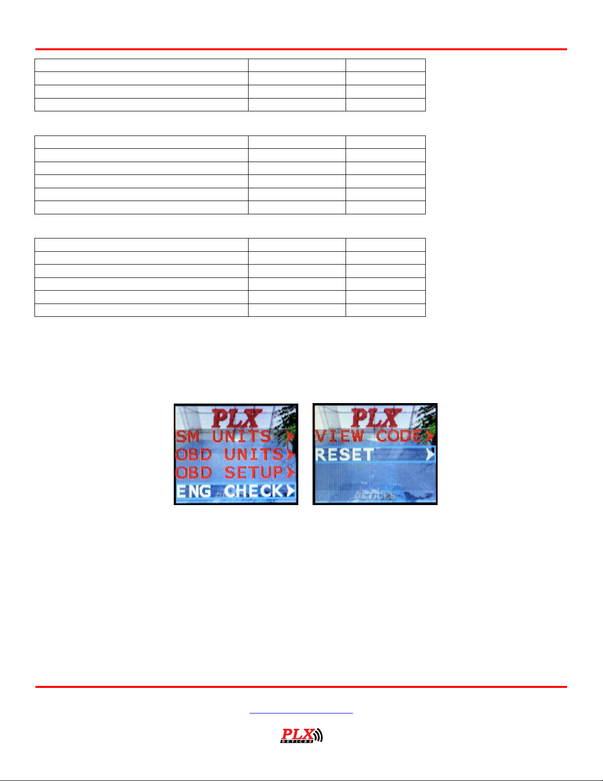
5 OBD II Sensors
The DM-100 OBDII in the OBDII Sensors Mode displays sensor information in a page format. To navigate
to this mode, please refer to section (2.4) navigating the menu system. By pressing the “RIGHT” and
“LEFT” button, toggles between the 5 available pages.
Page1:
Page2:
Page3:
Page4:
Version 2.0 May 16, 2013
www.plxdevices.com
(408)745-7591
Page 18
18
Narrowband O2 Sensor Voltage Sensor 2 Bank 1
Volts
Volts
Narrowband O2 Sensor Voltage Sensor 1 Bank 2
Volts
Volts
Narrowband O2 Sensor Voltage Sensor 2 Bank 2
Volts
Volts
Fuel System Status
Open or Closed
Open or Closed
Sensor
Standard Units
Metric Units
Barometric Pressure
inHG
Kpa
Absolute Engine Load
%
%
Fuel Level
% % Relative Fuel Pressure
PSI
Kpa
Ambient Air Temperature
Fahrenheit
Celsius
Sensor
Standard Units
Metric Units
Catalytic Converter Bank 1 Sensor 1
Fahrenheit
Celsius
Catalytic Converter Bank 2 Sensor 1
Fahrenheit
Celsius
Catalytic Converter Bank 1 Sensor 2
Fahrenheit
Celsius
Catalytic Converter Bank 2 Sensor 2
Fahrenheit
Celsius
ECU Voltage
Volts
Volts
Page5:
Page6:
Users Guide: iMFD User Guide
6 Engine Check
6.1 Viewing Trouble Codes
This mode views your trouble codes. A typical trouble code looks like the following
P0171
First Character – System
The first character identifies the system related to the trouble code.
P = Powertrain
B = Body
C = Chassis
U = Undefined
Second Digit - Code Type
Version 2.0 May 16, 2013
www.plxdevices.com
(408)745-7591
Page 19
Users Guide: iMFD User Guide
19
The second digit identifies whether the code is a generic code (same on all OBD-II equipped vehicles), or a manufacturer specific
code.
0 = Generic (this is the digit zero -- not the letter "O")
1 = Enhanced (manufacturer specific)
Third Digit - Sub-System
The third digit denotes the type of sub-system that pertains to the code
1 = Emission Management (Fuel or Air)
2 = Injector Circuit (Fuel or Air)
3 = Ignition or Misfire
4 = Emission Control
5 = Vehicle Speed & Idle Control
6 = Computer & Output Circuit
7 = Transmission
8 = Transmission
9 = SAE Reserved
0 = SAE Reserved
Fourth and Fifth Digits
These digits, along with the others, are variable, and relate to a particular problem. For example, a P0171 code means P0171 System Too Lean (Bank 1). To lookup your particular code, visit http://www.obd-codes.com/trouble_codes/
6.2 Resetting Trouble Codes
This mode is used to clear your engine check light. The process should take approximately 5 seconds.
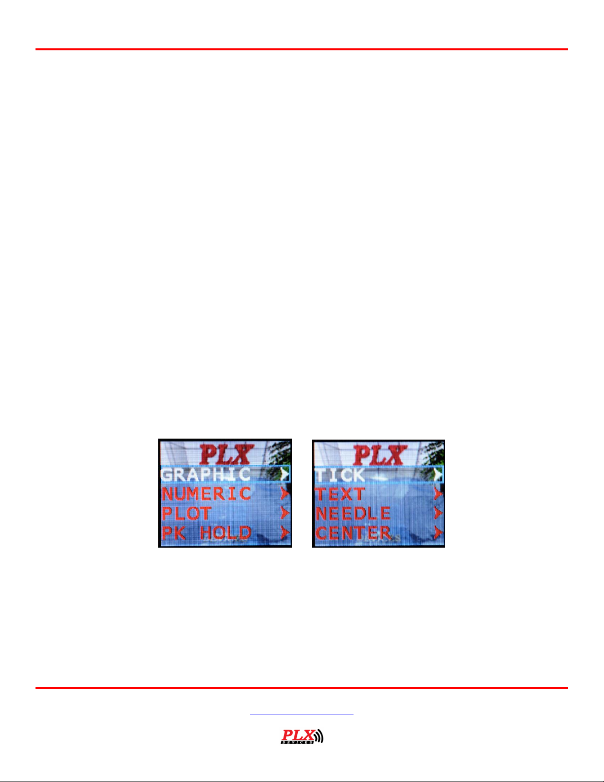
7 Setup
To enter setup mode, press the “down” button while you’re in the View OBDII Sensor Data menu. This will
take you to the first setup menu option.
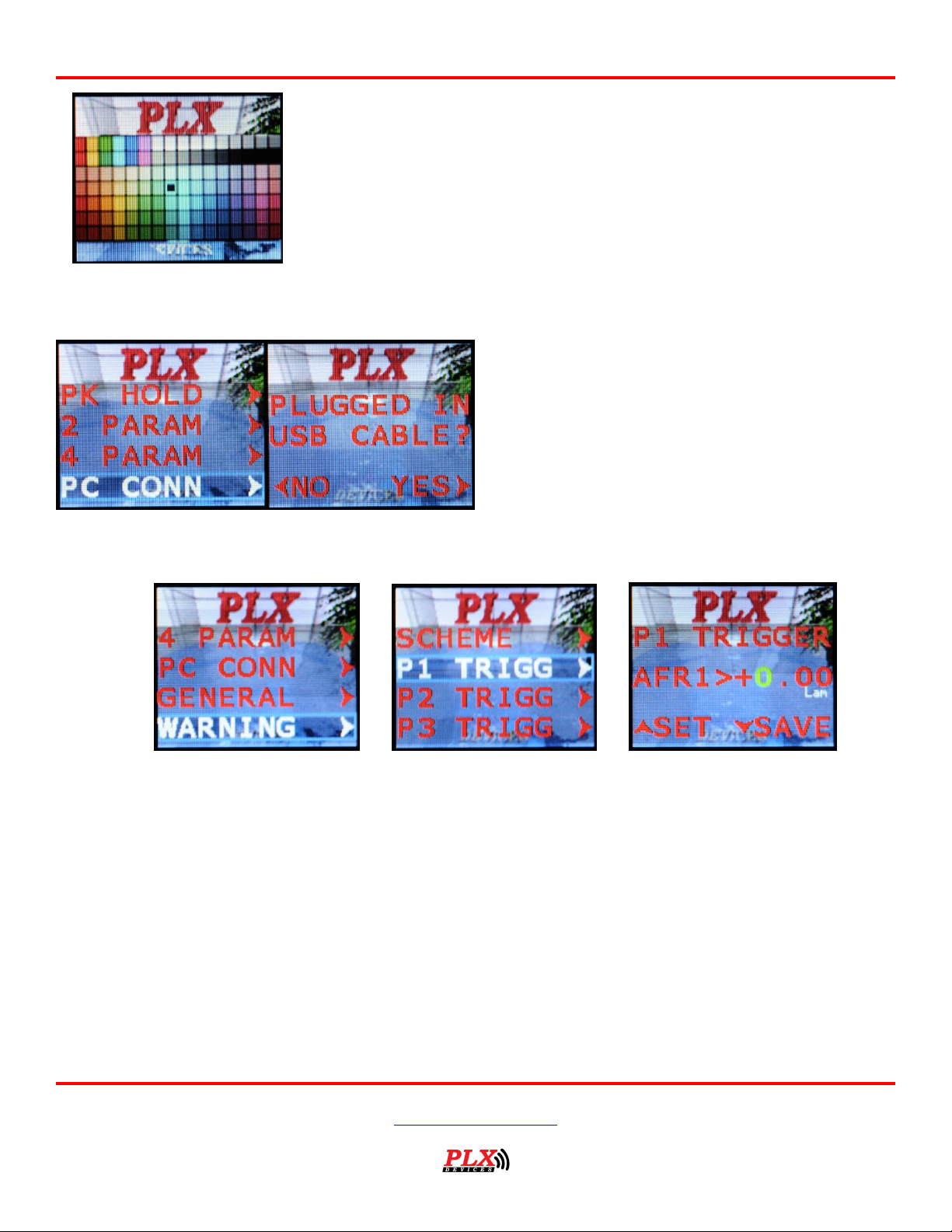
7.1 Customizing Colors
Each gauge style can be customized to any color and any wallpaper by navigating through the above
menus.
Version 2.0 May 16, 2013
www.plxdevices.com
(408)745-7591
Page 20
20
UP, DOWN, LEFT, RIGHT – Moves the cursor to select your desired color.
LEFT – RIGHT (Simultaneously 3 seconds) – To exit the color palette.
The DM-100 must be in this menu for the PC to
communicate with the device. Toggle to this menu
if you want to upload wallpapers, custom gauge,
and/or update your sensor table.
7.2 Connect to PC
Users Guide: iMFD User Guide
7.3 Warnings
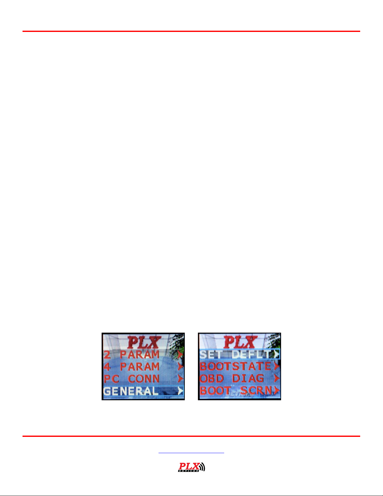
The DM-100 can monitor up to 4 parameters for warnings. The DM-100 monitors 4 parameters
simultaneously and evaluates if any trigger points have been exceeded. If any of the 4 parameter trigger
points have been exceeded then the DM-100 will evaluate if a warning message should appear on the
display based on the ‘scheme’ setting. To better explain this feature, please take a look at an example.
Example: Parameter 1 is set to read AFR, Parameter 2 is set to read EGT, Parameter 3 is set to read Oil
Temperature and Parameter 4 is set to read Boost. The trigger points are set to the following.
Trigger point settings:
(Parameter 1) AFR > 15.0
(Parameter 2) EGT > 800
(Parameter 3) Oil > 110
(Parameter 4) BST > 15
Example:
Version 2.0 May 16, 2013
www.plxdevices.com
(408)745-7591
Page 21
Users Guide: iMFD User Guide
21
If the DM-100 measures the following values and the ‘scheme’ setting is set to P1 OR P2, this means that
if the Parameter 1 is TRUE OR Parameter 2 is TRUE, a warning will trigger. Parameter 3 and 4 are ignored.
Measured values:
(Parameter 1) AFR = 14.0 FALSE
(Parameter 2) EGT = 850 TRUE
(Parameter 3) Oil = 105 FALSE
(Parameter 4) BST = 20 TRUE
Since Parameter 2 is TRUE, a warning will trigger according to the above example.
What will happen if the scheme is set to P1 AND P2? This means that if Parameter 1 is TRUE AND
Parameter 2 is TRUE, a warning will trigger. Since Parameter 1 is FALSE, a warning will not trigger.
Parameter 3 and 4 are ignored.
What will happen if the scheme is set to P1 OR P2 OR P3 OR P4? This means that if any parameter 1-4 is
TRUE, a warning will trigger. For this example, a warning will trigger.
What if the scheme is set to P1 AND P2 AND P3 AND P4? This means that all parameter 1-4 must be true
to trigger a warning. For this example, a warning will not trigger.
Several other scheme combinations are available for you to fully customize your warnings as they work on
the same principal as the example above.
When a warning triggers, a flashing red and white background will appear with “WARNING” on the top of
the screen. The parameter which is TRUE will also be displayed in the same format as 4 parameters
gauges. This allows you to see the actual value measured instantaneously.
*Please note if you are in the OBDII Sensors Pages, Intelligent Warning is NOT monitored. It is ONLY
monitored while in Standard Gauges.
*When a warning is triggered, touch RIGHT and LEFT (simultaneously for 3 seconds) will take you directly
to the warning setup menu.
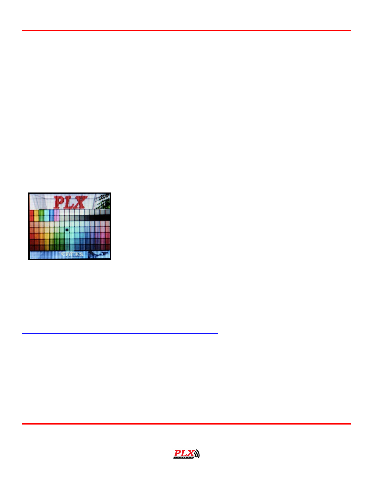
7.4 General Setup
Version 2.0 May 16, 2013
www.plxdevices.com
(408)745-7591
Page 22
Users Guide: iMFD User Guide
22
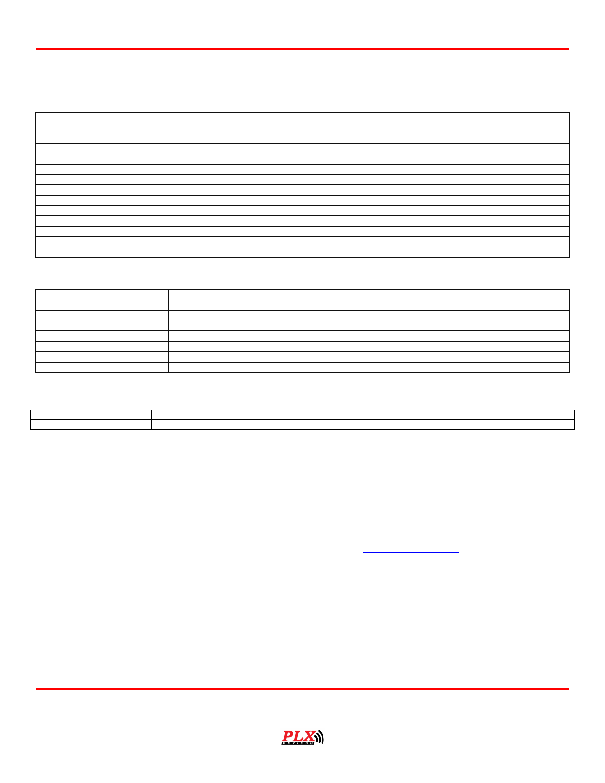
UP, DOWN, LEFT, RIGHT – Moves the cursor to select your desired color.
LEFT – RIGHT (Simultaneously 3 seconds) – To exit the color palette.
7.4.1 Set Defaults
This option resets the DM-100 back to factory defaults. Custom wallpapers, custom gauge and sensor
tables are NOT affected.
7.4.2 Boot State
This option allows you to set which gauge to be displayed when the DM-100 boots up for the first time.
7.4.3 OBD Diag
In this mode, your DM-100 can be connected and controlled from the PC with additional 3rd party
software.
7.4.4 Boot Screen
This option allows you to select from the 8 available wallpapers stored on the DM-100 to be displayed for
5 seconds during boot up.
7.5 The Color Palette
7.6 Wallpaper Backgrounds
Up to 8 wallpaper images can be uploaded to the DM-100. The DM-100 comes with 8 standard images;
however you may use any color image formatted to the size of (160 x 128 pixels) as your wallpaper
background. You may want to upload your company’s logo, a picture of your vehicle, or any other image
your imagination takes you. Your custom wallpaper can be uploaded to the DM-100 via USB port with the
http://plxdevices.com/product_info.php?id=MULTDM100TOUCH. You have the option to select a different
wallpaper background for analog gauges, digital gauges, plot gauges and 4 parameter gauges. The
wallpaper image will automatically be superimposed under the gauges.
7.7 Sensor Table
As more sensor modules are available the Sensor Table must be updated for the DM-100 to properly
interpret and detect new sensors. You will know if your sensor table needs to be updated if your DM-100
does not properly detect your new sensor module at boot up. The sensor table is stored in the flash
memory of the DM-100 control box and can be updated by connecting to the USB port on your PC. The
http://plxdevices.com/product_info.php?id=MULTDM100TOUCH, is used to upload the updated sensor
table. Please refer to the DM-100/200 Utility user guide for more details.
Version 2.0 May 16, 2013
www.plxdevices.com
(408)745-7591
Page 23
23
Physical Dimensions (Box)
4" x 2.875" x 1.125" (104mm x 75mm x 28mm) L x W x H
Power Consumption
1.5 Watts
OBDII/CAN Protocols
ISO-9141, VPW, PWM, KWP 2000, 11Bit CAN, 29Bit CAN
OBDII PIDs
30 PIDs
Compatible HDD
HDD-100 Touch
Processors
Custom PLX 32 Bit Processor, Custom PLX GPU (Graphics Processor Unit)
Operating Temperature
0 - 85 Deg C
Operating Voltage
10V-18V
Automatic Sensor Detection
YES
Human Interface
4 Position Capacitive Sense Touch Screen
PC Interface
USB 2.0
# Sensor Modules
1-32
Firmware Upgradeable
Yes
Enclosure
Extruded Aluminum
Physical Dimensions
2 1/16" (52mm) x 0.7" (18mm)
Display Technology
OLED 160 x 128 (20480 Pixels)
Color Depth
16 Bit
Viewing Angle
180 Degrees
Polarization
None (Viewable with polarized sunglasses)
Power Consumption
0.6 Watts Typical
Cable Length
6ft (~2m)
Operating Temperature
0 - 85 Deg C
Version 1.0 (1/1/08)
Initial release
Version 2.0 (5/16/13)
Added additional information for DM-100 OBDII Touch
8 Technical Specifications
8.1 DM-100 OBDII Touch Control Box
8.2 DM-100 Display
Users Guide: iMFD User Guide
9 Revision History
TERMS OF USE
PLX Devices Inc. does not guarantee product functionality with any ECU, data logger or other devices that uses the output signals. Implementation and
integration of the PLX products with any other device(s) must be done at your own risk. Improper installation and usage may l ead to engine damage.
Mount and install PLX products in a location where it does not obstruct the driver’s view and/or ability or safely control th e vehicle.
LIMITED WARRANTY
PLX Devices Inc. warrants this product to be free from defects for 1 year from the date of purchase. If applicable, Oxygen sensors and other nonserviceable items are excluded from stated warranty. Serviceable goods must be determined by PLX Devices to be defective befo re any warranty or
replacement is issued. PLX Devices’ obligation under warranty shall be limited to repairing or replacing, under the discretion of PLX Devices, any part
proven defective. This warranty is limited to the repair or replacement of parts in the manufactured good and the necessary l abor done to affect its
repair or replacement.
SERVICE UNDER WARRANTY
In the unlikely event that your PLX Devices hardware should fail during the warranty period, a Return Material Authorization number (RMA) must be
first retrieved from PLX Devices Customer Support. Support can be contacted thro ugh email: [email protected] or by phone: 408-745-7591.
All serviceable goods must be packaged securely with proof of purchase, RMA number, with all shipping charges prepaid and shi pped to PLX Devices
Inc. Goods returned under warranty must be received by PLX Devices Inc. within ten (10) business days after the RMA number ha s been issued. Goods
received after this period is subject to fees for the service of repair or replacement. All repaired or replaced items shall be warranted for the remainder
of the original product warranty.
RETURNS AND RESTOCKING FEE
A 15% restocking fee will apply to applicable PLX Devices products for refund. All returns are to be packed in original condi tion including packaging,
documentation, manuals, and accessories. Returns that do not include all the accessories and components may be returned to th e customer or charged
on a per item basis. The customer assumes responsibility for product until receipt at PLX Devices Inc., shipping via an insurable carrier is
recommended. Any unauthorized shipping charges will be billed to the customer or shipment will be refused.
DISCLAIMER
PLX Devices Inc. shall not be liable for direct, special, incidental, or consequential damages resulting from any legal theory including, but not limited to,
lost profits, downtime, goodwill, damage, injury to persons, or replacement of equipment and property due to improper installation, integration and/or
misuse of any PLX Devices Inc.’s product(s). This warranty applies to the original purchaser of product and is non-transferable. All implied warranties
shall be limited in duration to the said 1 year warranty period.
Version 2.0 May 16, 2013
www.plxdevices.com
(408)745-7591
 Loading...