

Page 1

M-12 Series Copyboard / C-12 Series Captureboard
Assembly and Setup Manual
This is the installation and assembly manual for the M-12 series Copyboard and C-12
series Captureboard
.
(The copyboard and/or captureboard are referred to as "the set" or "the main unit" in this manual.)
To the Customer
Special skills are required to install the set. Never try to assemble the
set yourself.
To the Dealer or Installation Tradesman
In the interest of the safety of the customer, please perform installation
work paying due attention to the strength of the installation location to
ensure that it can bear the load of the main unit, printer, and installation
parts.
TABLE OF CONTENTS
1. Please Read in the Interest of Safety ....................................................... 2
2. Packaging List ............................................................................................ 3
3. Installation Procedure ............................................................................... 4
4. Assembly of the stand ................................................................................4
5. Wall Mounting ............................................................................................. 7
6. Assembly of the Printer Table ................................................................. 10
7. Connection to the set .............................................................................. 12
8. Test Print ...................................................................................................17
9. Changing the Height of the Unit ............................................................. 18
Page 2
2
1. PLEASE READ IN THE INTEREST OF SAFETY
Warning
• If you are not a qualifi ed assembly serviceperson, do not perform installation procedures.
• Please be sure to perform the installation and assembly based on this manual. Incorrect installation
or assembly will be the cause of injury.
• Please have 2 or more persons lift the main unit when installing or removing it.
Also, be sure to lock the stand's casters before installing or removing. If not, the stand could slip un-
expectedly, resulting in accidents.
• To prevent dropping the strength of the installation location and the anchoring method must fully bear
over a long period the load of the main unit, printer, and installation parts. The installation should also
be performed to fully withstand an earthquake. Incorrect installation can result in the main unit falling
and causing injury.
• Please use M6 or equivalent screws for the wall mounting portion. Use of screws other than M6 or
equivalent can result in the main unit falling and causing injury.
• Please mount to a post in the wall or a sturdy wall stud. When the mounting positions of the main unit
are not reached, please use optional wall support fi ttings.
• Please use hardware like anchor nuts and anchor bolts for mounting on a concrete wall.
• Be sure to install the stabilizers supplied with the stand at each of the 4 locations (to prevent toppling).
• The AC adapter box is for storing the AC power adapters of the main unit and printer. The AC power
adapters and the power cords heat up. Read the "Important Safety Information" in the main unit's
"User's Manual" carefully and store them properly.
CAUTION
• When a printer is mounted on the set, attach the Velcro and printer guides so that the printer does not
slip off. If not, the printer could fall when moving the set, resulting in damage or injury.
* The Velcro is meant to prevent slipping, not to fasten the printer in place.
* Velcro is a registered trademark of Velcro Industries.
Page 3

3
The packaged contents will differ depending on the purchased Series.
Please open the carton and check the parts.
In the rare event that something is missing, please contact your store of purchase.
■
List of Items in Package
Main unit: 1 unit (standard type or wide type)
Wall mounting brackets: × 4, M4×8 screws × 16 (for wall mounting)
Printer table (1 set): Printer table × 1, Brackets × 2, M4×8 screws × 4, M3×6 screws × 10, Cushions × 2, Printer guides × 2,
Velcro× 2 sets
AC adapter box (1 set): With 2 masking screws
Cable covers for copyboard: Standard type×1, Wide type ×2
AC power adapter (with power code): × 1 (HEC-AP065-24V)
Markers: × 4 (One each of black, red, blue, and green)
Eraser: × 1
USB cable: × 1
Documentation: Instruction manual × 1, CD-ROM × 1, Quick Guide × 1, Assembly and Setup Manual (this manual) × 1
TOOL BOX Software Operation Manual × 1
■
Printer package*: One unit
Please check the user’s manual of the printer for a list of contents for the printer package.
2. PACKAGING LIST
■
Stand packaging list*
T-shape legs (with casters) × 2, Hexagonal socket screws × 8, Flat washers × 8, Horizontal bars × 2, Hexagonal
wrench × 1, Stay × 1, Nylon bushing × 1, M3×6 screws × 2, Stabilizers × 4, Frame caps × 2, Pipe caps × 4, Lock-
screws × 2, Cable covers for stand × 2 (Standard type × 1, Wide type × 1)
* The printer and stand may be options.
Page 4
4
3
4
1
2
3
4
1
2
* The stand may be an option.
(Please consult with a dealer or installation tr adesman. Installation work should not be done by the customer.)
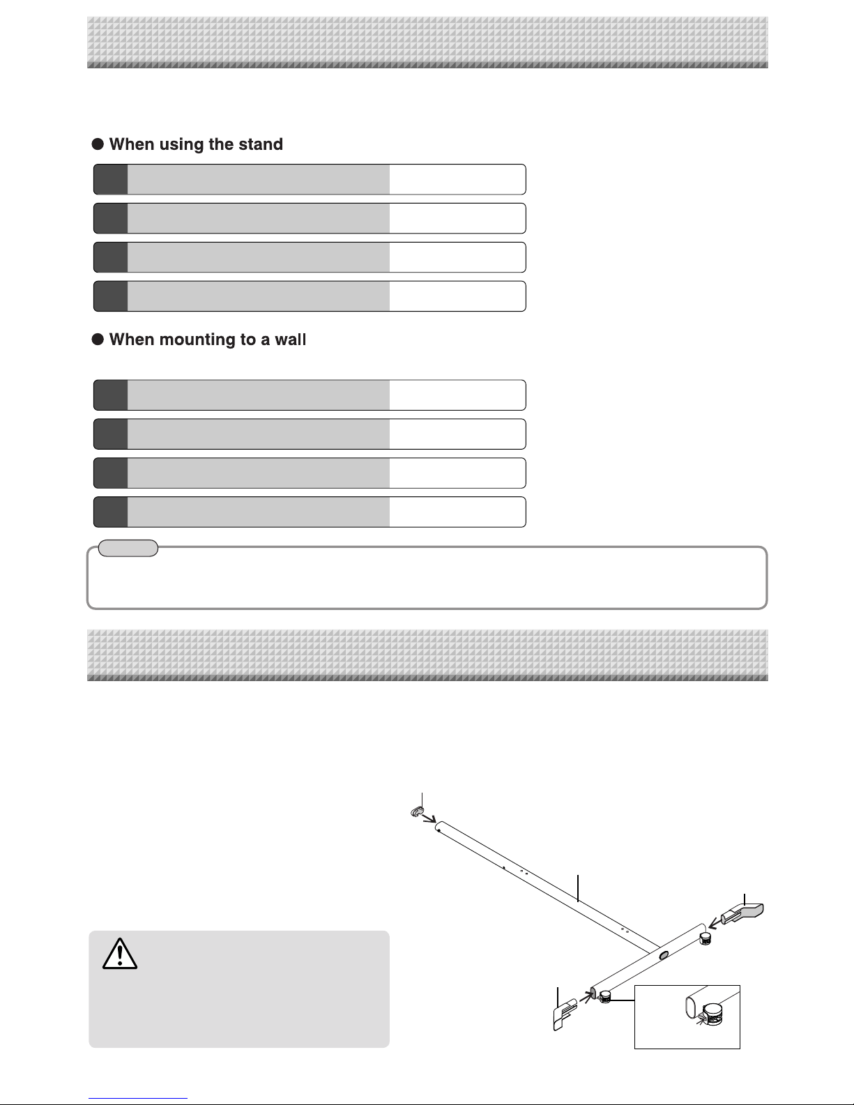
4. Assembly of the stand
See Page 4
6. Assembly of the printer table
See Page 10
7. Connection to the set
See Page 12
8. Test print
See Page 17
6. Assembly of the printer table
See Page 10
7. Connection to the set
See Page 12
8. Test print
See Page 17
5. Wall mounting
See Page 7
The installation method will change depending on the type of installation. Please perform installation and
assembly according to the following procedures.
4. ASSEMBLY OF THE STAND
Frame Cap
Stabilizer
T-shape leg
• Diagrams of printers that appear in this manual are representative illustrations.
The illustration will differ from the actual printer. Check the owner's manual of your printer for information about the names of
the connectors and their locations and use.
Caster
Stabilizer
Use the same method to assemble the left and
right sides of the stand.
(1) Press-fi t the frame cap onto the top
of the T-shaped legs.
(2) Attach the stabilizers to the front
and back of the T-shaped legs.
Insert the stabilizers securely all the way in.
(3) Lock the caster stoppers.
Press the bottom portion of the stoppers to lock
them.
CAUTION
To prevent toppling, be sure to install the stabilizers at each of the 4 locations. The toppling of this
machine could cause bodily injury or damage the
machine.
3. INSTALLATION PROCEDURE
Note
* The printer may be sold separately.
Page 5
5
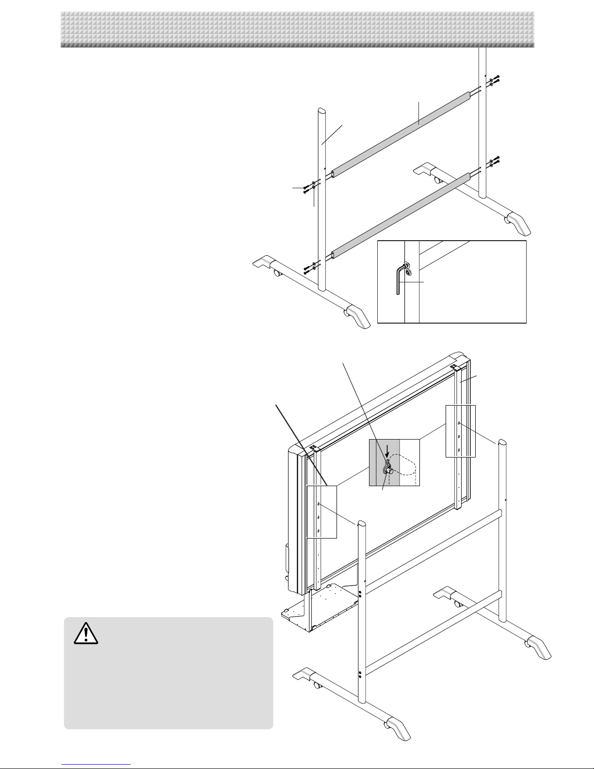
(4) Attach the two horizontal bars to the
T-shape legs.
Use hexagonal socket screws (M5) and flat wash-
ers (M5) to attach.
Partially fasten using the hexagonal wrench (M5), then
tighten securely after the upper and lower horizontal
bars have been attached.
(5) Place the stand’s hooks in the
mounting holes in the support fit-
tings and insert the grooves in the
hooks securely.
There are 3 hole positions. By changing the position,
the installation height can be changed among 3 lev-
els in 100 mm units (1770, 1870, and 1970 mm (the
maximum height)).
(6) Mount the printer table to the main
unit.
See Page 10 for information about the assembly and
installation of the printer table.
* Installation of the printer table is not required when
the main unit is used only for USB memory storage.
Hexagonal wrench (M5)
T-shaped leg
Horizontal bar
Hexagonal socket screw (M5)
Flat washer (M5)
CAUTION
Please have 2 or more persons lift the main unit
when installing it or making a height adjustment. If
the unit is dropped or falls over, this could cause
unforeseen injury.
Check that the hook is securely inserted into the
installation hole. Insecure installation could result
in the unit falling and causing bodily injury or damage to the unit.
Mounting hole
Hook
The rear
frame
4. ASSEMBLY OF THE STAND
Page 6
6
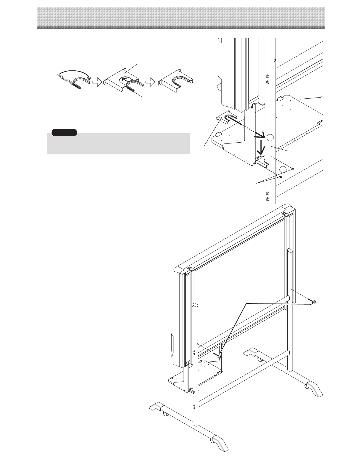
(7) Install the stay to the printer table.
Insert the nylon bushing into the stay.
Insert the stay into the pipe of the stand.
Mount the stay to the
printer table using two M3 screws.
Check again that the grooves in the stand’s hooks are securely inserted in the mounting holes in the support fi ttings.
(8) Lock the main unit and stand with the two
locking knobs.
3
2
Stay
Pipe
M3 screws
Locking knobs
Stay
Nylon bushing
Notice
4. ASSEMBLY OF THE STAND
Page 7

7
1077 mm
1200 mm
1077 mm
1200 mm
(1) Determining the installation location
The diagram indicates the dimensions of the installa-
tion positions. The installation position is the same for
both the standard type and the wide type.
The installation of the main unit to the wall is per-
formed after the printer table is assembled and at-
tached to the main unit. See Page 10.
• When the Wall Is Concrete
Embed the commercially available anchor bolts or
anchor nuts for M6 at the installation positions. (See
below)
• When the Wall Structure Is Plywood or
Plaster Board, etc.
Please check that a post or stud is located at the
installation position indicated by the dimensions.
When a post is not located at the target installation
position, please use a wall support fitting that is
available separately. Attach a wall support fi tting to
the post or stud.
• When the building does not have posts, please
use the stand.
• Separate optional items are available when the
standard wall mounting is not possible, or when
installation will be made to a partition.
Stud, etc.
Wooden Walls Wood screws
Make a suitable hole with an auger and
attach the Copyboard with wood screws.
Concrete Walls Anchors
Make a base hole in the wall with a drill. Insert the anchor. Fasten the main
unit with screws.
Please use a drill of the hole diameter specifi ed for the anchor.
Steel Walls Phillips head tapping screws (Pan head)
Check that the steel wall is reinforced and use a drill a hole of suit-
able diameter, then attach the main unit with tapping screws.
Reference: Installation Method for Various Wall Materials
Please perform an installation that suits the wall material.
Please install the main unit to posts or studs when the wall surface is of insuffi cient strength.
Installation Wall Material
Installation Method
5. WALL MOUNTING
Note
Page 8

8
(3) Attach the 4 supplied wall-mount brackets to the main unit using M4×8 screws.
Four screws for each bracket. (Total 16 screws.)
(2) Stick the cushions on the
printer table, then mount the printer table on the main
unit.
Peel off the protective sheets from the cushions’ adhesive surfaces.
Stick the cushions (2) on the back of the bracket.
See page 10 for instructions on assembling and mounting the printer table.
When mounting the
printer table after installing the main unit on a wall, see page 10.
* There is no need to mount the
printer table when only storing data in the USB memory storage.
Protective sheet on
adhesive surface
Cushion
Cushions
Back of bracket
Wall-mount bracket
M4 x 8 screw
5. WALL MOUNTING
Page 9

9
(4) Attaching and anchoring the main unit to a wall or wall support fi tting.
(The anchoring method will differ depending on the wall mounting method.)
Installing on a Concrete Wall
Anchor nut, etc.
M6 screw
Mounting to a Post
M6 wood screw
5. WALL MOUNTING
Page 10

10
Printer Table Right-side Installation Printer Table Left-side Installa-
The printer table can be installed at either the left or right side. The installation method is the same.
Determine whether to install the printer table on the left or right side in consideration of the position of the
power outlet in the wall, etc.
The method of assembling the printer table is the same for stand placement and for wall mounting. The assembly diagrams
omit the stand.
M4 X 8 screws
(1) Temporarily fasten the right and left brackets to the main unit using four M4×8
screws in the order of Steps to .
Right bracket
Left bracket
M4x8
screws
Front screw
hole
Front screw
hole
When mounting the printer table after
installing the main unit on a wall
Use four M4×8 screws to temporarily fasten the
left and right brackets to the four holes in the
bottom of the main unit.
Screws hole
Screws hole
Screws hole
Screws hole
2
4
1
3
(2) Temporarily fasten the printer table to the
brackets with six M3 x 6 screws.
M3 x 6 screw
Printer table
M3 x 6 screw
6. ASSEMBLY OF THE PRINTER TABLE
If the printer touches the wall, move the printer
table forward, then fasten it in place using four
M3x6 screws.
* When installing using a stand, do not move the printer table
forward and fasten it in place. Doing so could result in the
printer table falling.
Page 11

11
(3) Securely tighten the screws that were fastened temporarily.
This completes the assembly of the
printer table.
* Appearance of printer is for illustration purposes.
(4) Secure the printer with the printer guides.
Mount the printer guides to prevent the printer from falling
when the main unit is moved.
Two sets of printer guides and two sets of Velcro are included
with the main unit.
Check the size of the printer and whether or not the feeding
tray can be set and determine the position in which the printer
is to be set accordingly.
When securing the printer using just one set of printer guides,
move it to the left or right side.
3
2
1
3
Velcro
Velcro
Printer guide
Printer guide
M3×6 screws
Peel off the backing paper from the Velcro and attach the Velcro
to the bottom of the printer.
Do not attach the Velcro to a sunken surface of the printer, or
it will not stick to the Velcro on the printer table.
Peel off the backing paper from the Velcro and attach the Velcro
to the printer table. Attach the Velcro in a position matching the
position of the Velcro attached to the printer.
Place the printer on the printer table, then fasten the printer
guide using two M3x6 screws. Press the printer guide against
the printer when tightening the screws.
*1. When the printer and the
printer table are the same size,
installation of the printer guides is not necessary.
*2. When installing using a stand, the position in which the
printer is secured differs for the standard type (center) and
wide type (towards the right).
6. ASSEMBLY OF THE PRINTER TABLE
Page 12

12
When an AC power adapter is used with a printer that has been verifi ed to be operational, although the printer type may differ
from that of the connection diagrams (e.g., a built-in type, or assembled type), the connections should be performed based on
the same main points. (In accordance with the printer specifi cations)
Step 1
Connecting the main unit
and printer
Step 2
Mounting the AC adapter box
to the printer table
Step 3
Wiring the cables in the
cable cover(s)
Step 1: Connecting the main unit and printer
* Appearance of printer is for illustration purposes.
Back surface
To DC INPUT connector
To Printer connector
To USB connector
Printer
USB cable (supplied)
To DC input connector
AC power adapter (supplied)
Printer AC power adapter
supplied with the printer
Note
7. CONNECTION TO THE SET
After connecting the main unit and printer, place the AC power adapters in the AC adapter box.
•
Flow of connection operations
Connect as shown on the diagram below. Do not yet connect the AC power plugs of the AC power
adapters to wall power outlets.
Page 13

13
AC power adapter
AC power adapter
Wire hole
AC power adapter's
power plug
Wire hole
Bracket
Hook
Hook
Bracket
Step 2: Mounting the AC adapter box to the printer table
After placing the AC power adapters of the main unit and printer in the AC adapter box, mount the AC
adapter box to the printer table.
(1) Place the AC power adapters of the
main unit and printer in the AC adapter
box.
• Place the AC power adapter's DC and AC side cords in
the AC adapter box's wire holes (push them in).
• The USB cable connecting the main unit and printer
should not hang down. Place any extra cable inside the
AC adapter box.
(2) Place the AC power adapters of the
main unit and printer in the AC adapter
box.
햲 Catch the hooks on the ends of the AC adapter box
onto the bottom of the left and right brackets (the
L-shaped part).
To catch the hooks, insert the AC adapter box from
the front of the printer table and pull to the rear. This
catches the left and right hooks.
햳 After adjusting the length of the AC power adapter's
cords, fasten the AC power adapter to the printer
table using the two masking screws.
WARNING
• The AC power adapters and the power cords generate heat. Be sure to wire them in such a way that they keep
apart. Do not bundle the cables together. Doing so could cause them to heat up, leading to fi re.
WARNING
• Be sure the power cords and USB cable do not get
caught when mounting the AC adapter box. Doing
so could damage the cords, leading to fi re or electric shock.
7. CONNECTION TO THE SET
Page 14

14
Bracket
Cable cover
Notice
Step 3: Wiring the cables in the cable cover(s)
The place of installation of the cable covers included with the main unit differs for the standard type and
wide type. (Note that they cannot be attached to the stand.) Also, the cable cover included with the stand
and designed specifi cally for the stand cannot be attached to the main unit.
Standard type: One cable cover specifi cally for the main unit
Wide type: Two cable covers specifi cally for the main unit
Stand: Two cable covers specifi cally for the stand (Standard type x 1, Wide type x 1)
Standard type: Use this for a 100V power cord
Wide type: Use this for a 200V power cord
(1) Attach the cable cover(s) according to
the type you have purchased.
Peel off the backing paper from the cable cover and
attach the cable cover fi rmly to the bracket.
[When the main unit is installed on a wall]
Attach the cable cover to the side of the bracket.
For the wide type, also attach one of the cable covers
specifi cally for the main unit to the bottom of the main
unit.
Insert the cable/cord into the slit in the cable cover.
* If the cable/cord is too short or too long, remove
the screws from the AC adapter box and adjust the
length.
• The included cable covers use a powerful adhesive seal.
The cable cover may be damaged or deformed if you try to
remove it and attach it in a different position.
Check the position of installation of the printer table before
attaching the cable cover.
7. CONNECTION TO THE SET
Page 15

15
Back surface
Cable cover specifically for the stand
AC power adapter's power plu
g
Wall power outlet
Cable cover specifically
for the main unit
Back surface
Cable cover specifically for the stand
AC power adapter's power plu
g
Wall power outlet
Cable cover specifically
for the main unit
Cable cover specifically
for the main unit
•
Example of connection cable wiring
[Standard type + stand installation]
[Wide type + stand installation]
• Do not use the cable cover specifi cally for the main unit if mounted on
the right as seen from the back of the printer table.
7. CONNECTION TO THE SET
Page 16

16
Back surface
AC power adapter's power plu
g
Wall power outlet
Cable cover specifically
for the main unit
[Standard type + wall installation]
7. CONNECTION TO THE SET
Page 17

17
Remove the printer cartridge installation seals and the protective sheet used for shipping before using the
printer for the fi rst time. Please see your printer manual for details.
(1) Press the ON/Standby
button of the main unit and switch on the power.
(2) Switch on the printer power.
(3) Open the top cover and open the paper tray.
(4) Install the print cartridge in the printer.
(5) Set A4 or letter size paper.
(6) Write or draw a diagram on the sheet surface.
(7) Check that the number of copies indicated in the display window of the main unit is “01” and then press
the Print
button. (On the C-12 Series, the display will indicate “PC” or “OP”. Check this indication and
press the Print button
.)
The main unit will read a one-screen portion and when this operation stops, the printing operation begins.
Depending on the printer, the display indicators might fl ash after turning on the power and continue to fl ash until printing
preparation is completed. If this occurs, refer to the printer manual and start the printing operation with the main unit after
checking that printing preparation has been completed.
8. TEST PRINT
Notice
Page 18

18
Mounting hole
Hook
Rear frames
lock-screw
Stand
Cable cover specifically for the stand
Please lock the casters by pressing the lower portion of the lock buttons of them.
(1) Unplug the AC power adapter's power plug from the wall power outlet and remove the power cord
from the stand's cable cover.
(2) Remove the printer from the printer table.
Disconnect the USB plug from the printer and the DC power plug, loosen the print-
er guide's fi xing screws and remove the printer.
(3) Remove the two locking screws (located at the left and right sides).
(4) Change the hole position of the main unit rear frame.
The main unit will disengage from the hooks when it is lifted up about 1 cm.
Fully hook the (2 left and right) installation holes of the main unit
rear frame onto the hooks of the stand.
If a stay (for preventing shaking) is mounted on the printer table,
insert the stay in its original position.
(See (7) on page 5 for mounting instructions.)
(5) Attach the locking screws to the 2 locations (left and
right) and tighten to the rear frames.
(6) Return to original by following the steps in reverse.
*The printer may be an option.
* Appearance of printer is for illustration purposes.
CAUTION
• Please have 2 or more persons lift the main unit when installing it or making a height adjustment.
If the unit is dropped or falls over, this could cause unforeseen injury.
• When a printer is installed on the main unit, remove the printer before performing this procedure. Failure to
do so could result in injury due to unexpected falling or tipping.
• Perform this procedure after unplugging the power plug from the wall power outlet and removing the power
cord from the stand's cable cover. If not, the stand could tip over unexpectedly, resulting in injury.
This is the height adjustment to the stand* at the time of setup. The height can be changed among 3 levels
in 100 mm units (1770, 1870, and 1970 mm (the maximum height)).
9. CHANGING THE HEIGHT OF THE UNIT
Page 19

Page 20

23-4604-08B
© 2008, PLUS Corporation
 Loading...