

Page 1

S B - 3 0 1 M K I I
P O W E R A M P L I F I E R
I N S T R U C T I O N M A N U A L
Page 2

Page 3

Contents
Introduction ...............................................................................................................2
Design Philosophy
Unpacking
Placement & Ventilation
Care & Maintenance............................................................................................5
Precautions
Front Panel Functions
Rear Panel Functions
Installation & Operation
Product Features
Loudspeaker Selection
Troubleshooting
Specifications
Index
....................................................................................................................4
................................................................................................................................18
...............................................................................................3
....................................................................................4
................................................................................................................6
........................................................................................7
.........................................................................................8
....................................................................................11
..................................................................................................14
.....................................................................................15
.......................................................................................................16
..........................................................................................................17
All operational, technical and descriptive material in this publication
is subject to change at any time without notice. For further product
information or queries, please contact your Plinius dealer.
Plinius products are designed and manufactured by
Plinius Audio Limited, New Zealand.
Page 4

Introduction
Congratulations on your decision to become the proud owner of this
Plinius SB-301 MKII Power Amplifier.
This manual has been prepared to help you understand the operation of your amplifier,
and to provide information about its design and the variety of ways it may be used.
We have designed and manufactured this amplifier to reproduce your favourite music
faithfully and accurately. With a little care and a full understanding of the operating
recommendations in this manual, your Plinius SB-301 MKII Power Amplifier will provide
years of high-quality, trouble-free performance.
Please take the time to read this manual thoroughly before using your amplifier.
SERIAL NUMBER
FINAL TEST CERTIFIED BY
2 PLINI U S S B - 3 0 1 M K I I
Page 5

Design Philosophy
From a distance you can see that the design of the Plinius products is more than
an applied styling exercise to the front panel. We have started from the ground up
to produce a casing for our electronics that is unrivalled in its physical strength and
visual simplicity.
Wherever possible we have reduced the number of parts needed and then invested
massively in refining and producing the remaining parts to the highest quality
achievable with state of the art computer controlled machines allied with expert
craftsman. Examples of this approach include the hydraulically formed corners on
the amplifiers giving much greater strength and the one piece housing for the remote
control that looks, feels and genuinely is robust.
As with music that you are not familiar with, truly innovative new designs can take time
to understand and enjoy. How of ten have you heard music that you were first unsure
of, that over repeated listening, has become a firm favourite?
Our designs are fundamentally different to many other companies, and we hope that
you will take the time to explore their unique character and qualities because we have
not made them different simply to be different. We genuinely believe that their visual
and tactile qualities do improve the experience of listening to music and that is our
design goal!
Ross Stevens
DESIGN DIRECTOR
3POWER A M P L I F I E R
Page 6

Unpacking
Open the box from the top and remove the accessories
from the foam end caps. You may now proceed to lift
the unit from the box, Once the unit is removed you can
proceed with the removal of the foam end caps. These
caps are designed to fit on the front and back of the unit
for maximum protection. Retain the packaging for future
transportation of this unit.
Placement & Ventilation
This Plinius product may operate at a moderately high temperature, especially during
extended listening sessions. With this in mind, we recommend the following guidelines
for placement and ventilation:
• The ideal location is upon a rigid stand, away from direct contact with any
temperature sensitive materials, furniture or deep pile carpets.
• Ventilation through and around the amplifier should be kept unimpeded.
• Ensure heat vents (slots in the base and lid) are not covered or restricted in any way.
• Equipment racks should be of an open type with no closed side panels and no
closed front or rear panels.
• Ensure a minimum of 400mm clearance on all sides of your Plinius unit to other
equipment and the shelf above. Ensure the space between the chassis and shelf
below the unit is unobstructed at all times.
• DO NOT place this unit in an enclosed cabinet.
• DO NOT stack other audio components on top of this unit.
• NOTE: This unit has been designed for use in moderate climates only, not for tropical
conditions.
The design of this Plinius product incorporates a very high level of mechanical
decoupling of the input and output. It can however still be influenced by acoustical
feedback in the operating environment. The use of acoustic cones or a suitably spiked
amplifier stand or table may further enhance the performance of this amplifier. Consult
your Plinius dealer for further advice if required.
4 PLINI U S S B - 3 0 1 M K I I
Page 7

Care & Maintenance
With simple care and maintenance your Plinius product can be kept looking and
operating like new for many years to come.
MAINTAINING THE CONNECTOR S
Exposed connectors such as the RCA connectors will be subject to environmental
factors, and over time the surface may degrade. This can be greatly reduced by fitting
readily available ‘RCA caps’ to reduce the effects of environmental elements on the RCA
connectors. These RCA caps or RCA shorting caps can also provide sonic benefits.
Connector cleaning products are also available to clean the RCA and cable connectors
and frequent checks and cleaning will help maintain a good signal connection.
NOTE: Do not use RCA shorting caps on output connectors or power amplifier input
connectors. Use RCA shorting caps on unused preamplifier stage input connectors only.
Standard RCA shielding caps can be used on any unused input or output connectors.
MAINTAINING THE SWITCHES
Switches should be maintained by using each various switch setting periodically.
Even if a switch or a switch setting is not used, it is a good idea to toggle small
switches and turn rotary switches though the full range of the switch several times in
succession to keep the contacts active. Performing this simple action will promote
longevity of the switch contacts.
SURFACE CLEANING
From time to time you may wish to clean the surface of your Plinius equipment to
remove dust, or any material build up from the atmosphere or on commonly used
controls. Your Plinius product is made up of parts that have a hard anodised or a
powder coat finish and will clean easily without being damaged.
Cleaning should be carried out using a soft cleaning cloth, dry or with either a small
amount of water or a very mild surface cleaner, while observing the following guidelines:
• As a safety precaution, always switch the equipment off prior to cleaning
• Always use a cloth that is sof t and clean
• Never use abrasives or polishing compounds anywhere on the unit
• Never apply liquid directly to the surface of the unit
• Use the cloth dry or with mild surface cleaners of either liquid or foaming type
• Apply only small amounts of cleaner to the cloth
• DO NOT rub the sur face but wipe clean only. Excessive rubbing may dull powder
coat or wear the screen printed text.
5POWER A M P L I F I E R
Page 8

Precautions
PLEASE TAKE SPECIAL NOTE OF THE FOLLOWING PRECAUTION S
BEFORE OPE RATING YOUR NEW AMPLIFI ER.
• The Plinius SB-301 MKII Power Amplifier can deliver in excess of 300 watts into 8
ohms. This amplifier is also capable of a very large peak current delivery.
• The Plinius SB-301 MKII Power Amplifier is capable of generating heat that could
have an adverse effect on other electronic equipment, furniture, etc.
• This amplifier is of direct-coupled design, and offers no protection from
preamplifiers that have a high DC component at their outputs.
• This amplifier operates at hazardous voltage levels. There are some alterations
that may be made by you, the owner. However, we recommend that any work
requiring removal of the lid be referred to a suitably qualified and experienced
service technician.
• DO NOT leave flammable material on the amplifier whilst running, as this could
pose a serious fire risk.
• DO NOT attempt to connect any input of this amplifier to its own outputs.
• DO NOT earth any output terminal or connect any of these terminals together
without following the instructions in this manual or seeking qualified assistance.
• DO NOT place this amplifier in any position where liquids, or any foreign material
may accidentally enter it.
• DO NOT connect any voltage source, short circuit, earth/ground or appliance
(other than suitable high fidelity loudspeakers) to the amplifier output terminals.
• DO NOT expose the unit to dripping or splashing.
• DO NOT place objects filled with liquids on the unit, e.g. vases.
• DO NOT place sources of naked flame on the unit, e.g. candles.
Some preamplifiers, processors, CD players etc, produce large switching pulses when
switched on causing a loud click through the loudspeakers. For this reason, turn
on all other equipment in your system before turning on your Plinius SB-301 MKII, or
ensure that the amplifier is in STANDBY. You will not experience this phenomenon with
Plinius preamplifiers.
6 PLINI U S S B - 3 0 1 M K I I
Page 9

Front Panel Functions
The front of the Plinius SB-301 MKII Power Amplifier incorporates all the facilities you
will require on a daily basis.
1
2 3
1. POWER LED
An LED in the centre of the front panel indicates the power is on. When first switched
on, the display will vary in brightness until the initialisation sequence is completed,
after which the LED remains lit.
2. MUTE SWITCH
It is not recommended practice to interfere with the input cables while the amplifier
is switched on and connected to the loudspeakers, so a Mute button is fitted to
interrupt the input signal. This allows you to connect and disconnect the input cables
without the necessity of turning the amplifier off, or to mute the signal momentarily
when desired.
3. STANDBY SWITCH
The standby switch operates the mute and low bias functions simultaneously to
enable the unit to be switched into a low bias power saving mode while keeping the
amplifier circuitry active. The amplifier is then ready for use and requiring only a few
minutes of warm-up before the very best of the amplifier’s sonic qualities may be
experienced. In Standby mode the LED is ON.
When the amplifier powers up from start, it will automatically go into Standby and
disconnect the speaker outputs. The standby switch or remote trigger can be used
to take the unit out of Standby and begin listening. NOTE: The Standby mode will
override mute. When taken out of standby the unit will return to the previous state.
7POWER A M P L I F I E R
Page 10
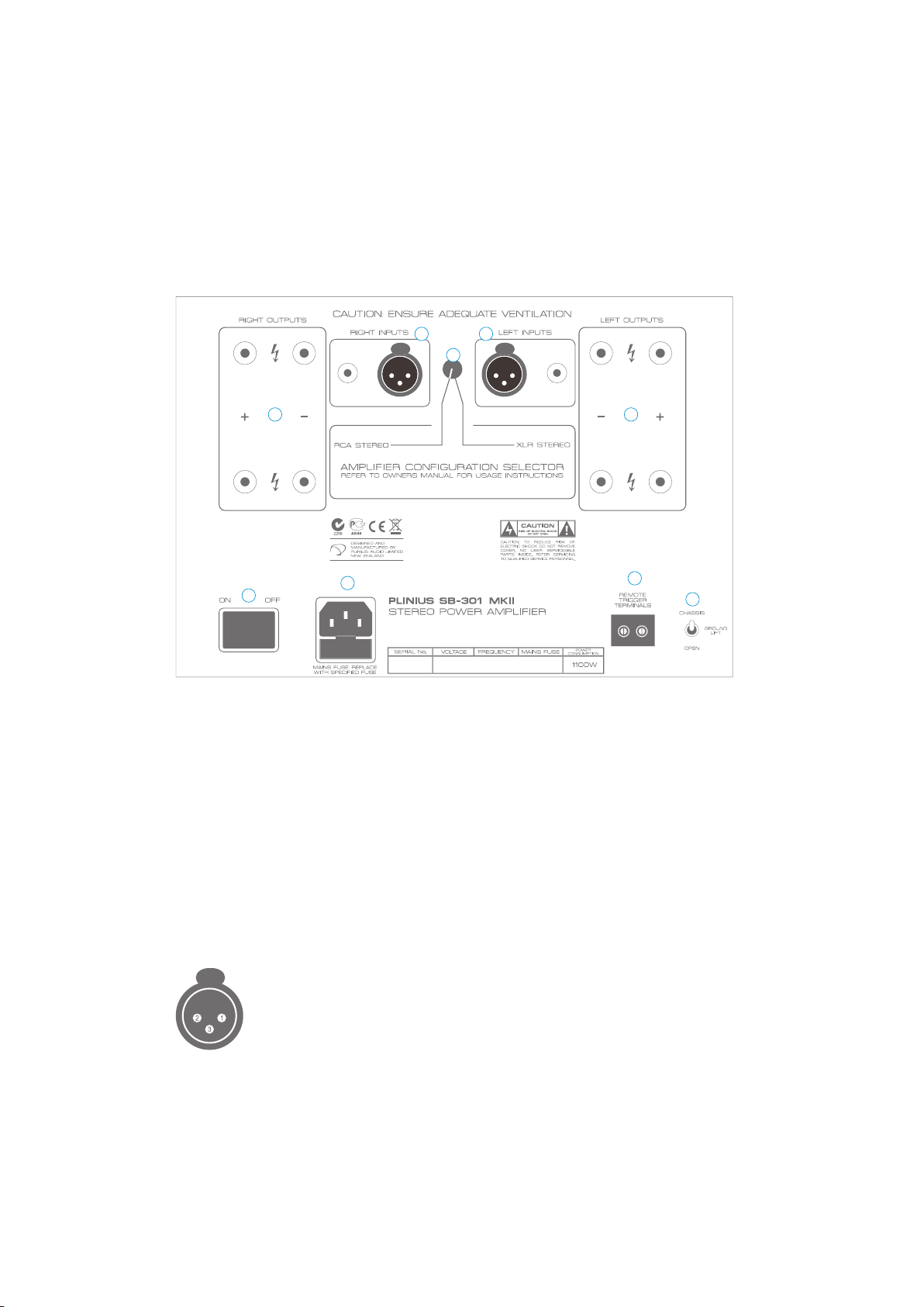
Rear Panel Functions
This panel incorporates all the terminals for connecting the input signals from your
preamplifier and output to the loudspeakers and mains supply. Be sure that you
understand your system’s requirements fully before you make any connection to this
amplifier.
1 1
2
33
4
5
6
7
1. INPUT TERMI NA LS
Input terminals for your Plinius SB-301 MKII Power Amplifier are easily accessible and
fitted near the top centre area of the rear panel.
RCA INPUTS: These standard RCA terminals are for use with unbalanced signals from
most signal sources such as audio preamplifiers.
XLR BALANCED INPUTS: XLR connectors fitted to this amplifier are for use with
balanced line signals from audio preamplifiers. Balanced signals are carried via a
three way cable that connects all three pins at each end of the interconnect cable.
The XLR input pin configuration used in all Plinius products is as follows:
PIN 1 to GND
PIN 2 to +Signal
PIN 3 to -Signal
NOTE: Because of the way balanced XLR inputs are configured it is not possible to
connect both XLR and RCA at the same time.
8 PLINI U S S B - 3 0 1 M K I I
Page 11

2. AMPLIFIER C ON FI GU RATION SE LE CT OR (ACS)
The Amplifier Configuration Selector (ACS) is a unique switching method that exploits all of
the operational features of your Plinius SB-301 MKII Power Amplifier. By using this switch it
is possible to operate your amplifier with either balanced or unbalanced signals.
The ACS switch options are:
• RCA STEREO: This option provides a stereo output via both left and right output
channels from a stereo signal connected to both left and right input RCA inputs.
• XLR STEREO: This option provides a stereo output signal from a balanced stereo
input signal connected to both the left and right XLR inputs.
BALANCED/UNBAL AN CE D SI GNALS
Balanced or unbalanced input options will depend on the type of signal available from
your preamplifier or other equipment. The Plinius SB-301 MKII provides both options
to allow you to choose the most suitable preamplifier for your purposes. Plinius
preamplifiers offer both balanced and unbalanced output options.
Balanced line is normally used to transmit signals in a professional environment.
Because balanced line effectively reduces or eliminates noise pick-up by the system
cabling, it has become increasingly more important in high-quality domestic high
fidelity systems.
Unbalanced leads such as single ended, RCA or coaxial are common and are used
in the majority of audio signal systems. The terminal plug and socket are most
commonly called RCA and can be found on your Plinius SB-301 MKII for use as the
standard input terminals for both left and right inputs.
3. OUTPUT TERM IN AL S
Output connections for the loudspeakers are provided on the left and right hand side
of the rear panel. Two parallel pairs of binding posts for each channel are fitted – these
provide ease of use with bi-wiring and multiple cables requiring a large contact area.
4. MAINS SWITC H
This heavy-duty rocker switch in the centre of the panel turns the Mains/Line Power
to the amplifier ON or OFF. An LED in the centre of the front panel indicates that
the power is on. When first switched on the power LED will vary in brightness for
ten seconds – this is an initialisation sequence, after which the power LED remains
lit. The amplifier draws a moderately high current when switched on. Despite the
“Soft Start Circuit” within the amplifier reducing current demand on the mains as the
amplifier is switched on, it is not good practice to rapidly turn the Mains switch on and
off repeatedly.
5. MAINS POWER C OR D IE C CONNECTOR
This connector is where the mains supply cable from your wall connects to the
9POWER A M P L I F I E R
Page 12

amplifier. You will notice that a fuse holder is mounted within this connection, and it
holds a mains fuse to provide surge and overload protection for your amplifier.
6. REMOTE TRIG GE R TE RM INALS
In order to integrate more effectively into a home theatre or multimedia system,
the Plinius SB-301 MKII has remote trigger terminals fitted to the rear panel. By
connecting a processor with a remote trigger signal to these terminals, the SB-301
MKII can be put in and out of Standby by the processor to which it is connected.
When in Standby the amplifier draws less current and will operate at minimum
temperature. The output relays are also open, disconnecting the loudspeakers. This
may be of advantage in a multi-amplifier and/or remote installations. Polarity of the
connections to the remote trigger is not important.
7. GROUND LIFT S WI TC H
This switch is located adjacent to the Mains Input Socket, and allows the signal
ground to be disconnected from the chassis. In some installations a hum loop
may exist due to duplicate ground paths from different equipment. Use this switch
to remove the connection from 0V to ground thus allowing some flexibility in your
particular set-up. Note that when using Balanced XLR inputs, the ground lift switch
should always be set to ‘chassis’.
10 PLINI U S S B - 3 0 1 M K I I
Page 13

Installation & Operation
WARNING: RISK OF ELECTRIC SHOCK. TERM INALS M ARKED WITH
SHOULD B E CONSIDERED HAZ ARDOUS LI VE AT ALL TI MES.
This amplifier operates at hazardous voltage levels. We recommend that any work
requiring removal of the lid be referred to a suitably qualified and experienced service
technician. DO NOT place this amplifier in any position where liquids or any foreign
material may accidentally enter it.
PLEASE READ & UND ERSTAN D THE PREC AUTIONS WITHIN THIS MANUAL
FOR PL ACEM ENT & OPERATION OF THIS P RODUCT.
CONNECTIONS
Connections to your Plinius SB-301 MKII should be made in the same order as they
are listed in this section. DO NOT attempt to connect your Plinius SB-301 MKII until you
have read and fully understood these instructions. Although these instructions refer
to the connection of a preamplifi er, the SB-301 MKII can also be safely installed into
multimedia systems by following the same installation guidelines. Should you require
any further assistance, please contact your Plinius dealer.
IMPORTANT: DO NOT POWE R U P YOU R AMPLIFIER U NTIL YOU HAVE
CONNECTED YOUR I NPUT/OUTP UTS CORRECTLY FOR YOUR SYSTEM.
PREAMPLIFER IN PU TS
Connect your preamplifier to the input of the Plinius SB-301 MKII using suitable single-
ended RCA or Balanced XLR interconnect cables only. If using single-ended RCA
inputs, connect your Preamplifier to the RCA inputs on the back of the Plinius SB-
301 MKII. Make sure you connect the red coded cable to the red RIGHT RCA input,
and the black (or white) cable to the black LEFT RCA input. Also make sure the RCA
connectors are a snug fit and are inserted all the way in.
PREAM PL IFIER SB-30 1 MKII IN PUTS
For XLR input connection, make sure you connect the RIGHT XLR input and LEFT
XLR inputs to the right and left outputs from your Preamplifier respectively. Use
the Amplifi er Confi guration Selector switch to select RCA STEREO if you are using
unbalanced RCA inputs or to select XLR STEREO if you are using balanced XLR inputs.
NOTE: DO NOT connect XLR and RCA at the same time, use only one or the other.
11P O W E R A M P L I FI E R
Page 14
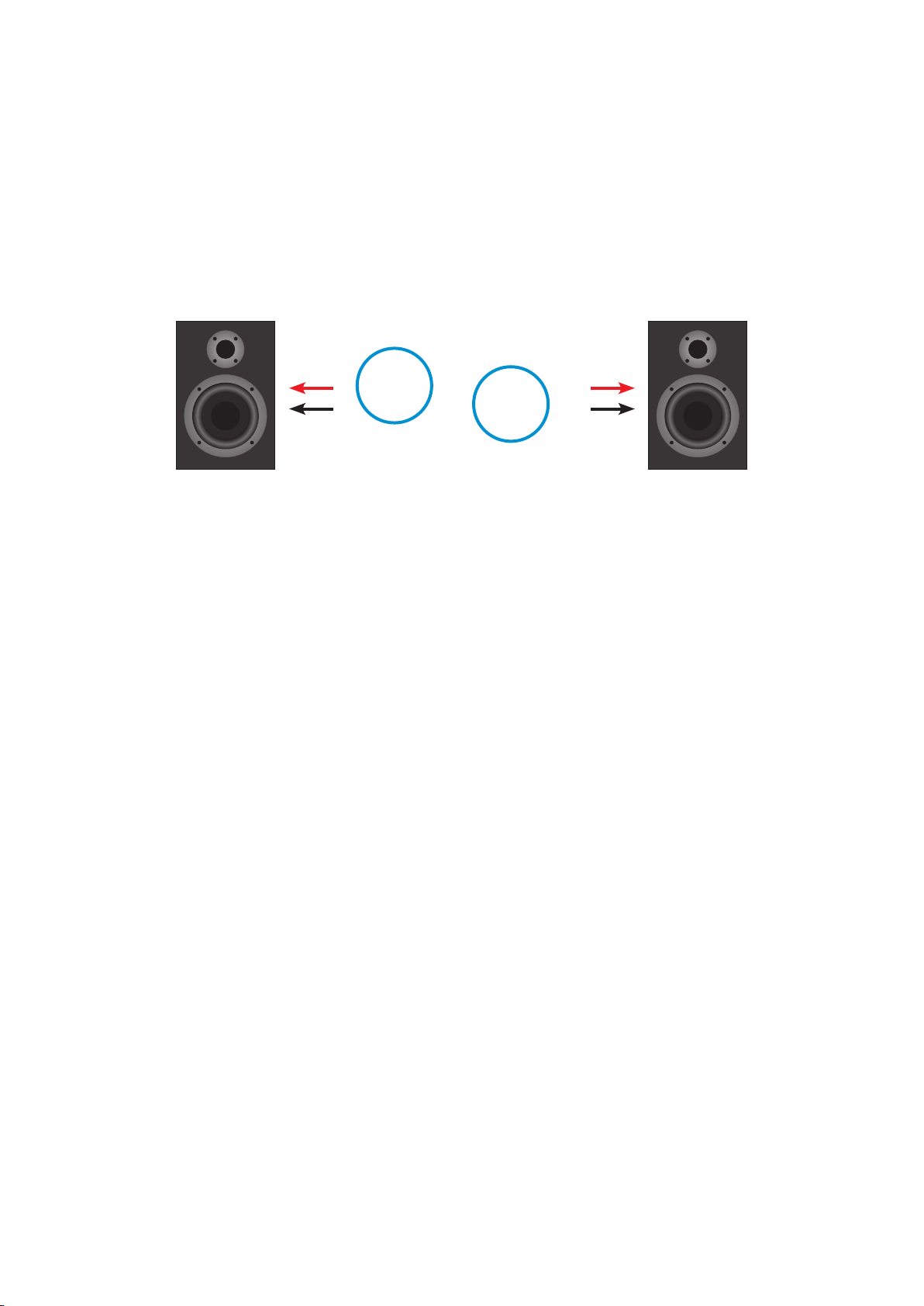
LOUDSPEAKER OU TP UT S
The connection of your loudspeakers to the output posts of the Plinius SB-301 MKII
must be made by an ‘instructed person’ or by ready made loudspeaker cables only.
Connect your left loudspeaker (ie. the one on your left when seated in your normal
listening position) to the left output terminals, ensuring that the red positive (+) terminal
on the amplifi er is connected to the red positive (+) terminal on your loudspeaker. Do the
same with the black or negative (-) terminals. Repeat this process for the right outputs.
+ RI GH T – OUTPU TS – L EFT + RIGHT S PEAKE R LEFT SP EAKER
TERMINATION QUALITY
Quality of the connections must be examined to ensure that high performance
trouble free operation is enjoyed. Check that the connections are tight but do not
over tighten. If bare wires are used make sure that no loose strands of wire short
cross the other terminals or the amplifier chassis. When using plugs such as
bananas, be sure to use good quality plugs with a firm fit.
BI-WIRING
Bi-wiring uses two pairs of loudspeaker cables for each channel loudspeaker. You
will notice that the rear panel of your Plinius SB-301 MKII has two pairs of output
terminals for this purpose. Be sure to follow correct practises for stereo and mono
configurations when using bi-wiring.
PHASING (OR PO LA RI TY )
It is important to achieve good stereo imaging in your listening room. By observing
the wiring instructions above, each power amplifier/loudspeaker combination should
be in phase. If you experience poor stereo image and/or a lack of bass, check that
the loudspeaker wiring has been connected correctly. We recommend that you use
one of the easily obtainable ‘test discs’ to help you ensure both phasing and channel
orientation are correct. If in doubt, consult your PLINIUS dealer for advice.
To achieve a sound performance that is correctly aligned to your room, make sure all
of the leads carrying signals for the right channel loudspeaker are connected to the
right input to the amplifier from your preamplifier or CD player etc. Signals for the left
channel should be wired in a similar fashion.
12 PLINI U S S B - 3 0 1 M K I I
Page 15

CONNECTING THE M AI NS S UPPLY
Firstly, check that the mains supply voltage printed on the rear of this amplifier is
similar to the mains supply voltage in your area. If in doubt, please consult your
Plinius dealer. Mains supply power connection is via the plug-in lead supplied with
your Plinius SB-301 MKII.
Check the wall outlet is switched OFF, then connect the local mains plug end of the
lead to the wall outlet. Check the SB-301 MKII is switched OFF, and connect the IEC
end of the cable to the IEC socket at the back of the SB-301 MKII. With the cord fully
connected, switch the wall outlet ON.
Now that your Plinius SB-301 MKII is configured correctly, switch the power switch on the
rear panel to ON. The display LED will cycle in brightness for approximately ten seconds
as the internal circuitry stabilises. Use the MUTE switch on the front panel to take the unit
out of MUTE and you can now enjoy your new Plinius SB-301 MKII Power Amplifier.
NOTE: This unit must be connected to a mains socket outlet with a protective ear thing
connection. The wall outlet socket or SB-301 MKII mains switch must be accessible at
all times in case of emergency.
WARM-UP PERIOD
You will find that the Plinius SB-301 MKII will become noticeably ‘purer’ in sound
after being on for a period of time. We recommend waiting at least 24 hours before
expecting the best quality of sound reproduction from your amplifier.
13P O W E R A M P L I FI E R
Page 16

Product Features
ERROR DETECTIO N
The Plinius SB-301 MKII Power Amplifier has in-built error detection. This will function
under the following conditions:
• When the amplifier is overdriven/clipped
• If any internal fuse is damaged.
Should either of these circumstances arise the amplifier will disconnect both
channels and mute the input. This condition will remain until the input signal level is
reduced or the damaged fuse replaced. When error detection is triggered the power
LED will turn off and the mute LED will pulse. The internal error LED (located towards
the front of the circuit board in the top cavity of the amplifier) will also light.
FUSE PROTECTIO N
When any internal fuse is damaged one or more fuse warning LEDs will light. These
LEDs are under the amplifier lid located near the centre of the main circuit board
with the rail fuse holders. If any of the internal fuse LEDs are glowing ensure that
your amplifier is switched OFF and disconnected from the mains supply. The lid of
the amplifier will need to be removed and the fuse adjacent to the lit LED should be
replaced. Replace them with the same type only.
IMPORTANT: DO NOT FIT A FUSE WI TH A HIGHE R RATING.
NOTE: that fuse failure may indicate a severe problem. Check all speakers and
speaker cables for damage etc. Should the amplifier continue to exhibit rail fuse
failure, contact your Plinius dealer.
MAINS/LINE FUS E
A Mains/Line fuse is fitted within the IEC Mains/Line socket on the rear of the amplifier.
A small drawer at the bottom of this socket may be removed (after the IEC plug is
removed) by levering it out with a flat blade screwdriver. The fuse fitted should be
rated as specified on the rear panel.
In the unusual event that this fuse should blow, you must first establish the cause of
this failure (such as power surges, damaged mains cable etc) before replacing the
fuse with one of the same rating and type.
IMPORTANT: DO NOT FIT A FUSE WI TH A HIGHE R RATING.
NOTE: Fuse failure may indicate a severe problem. Should the amplifier continue to
exhibit mains fuse failure contact your Plinius dealer.
14 PLINI U S S B - 3 0 1 M K I I
Page 17

Loudspeaker Selection
Your Plinius SB-301 MKII Power Amplifier is designed for use with high fidelity
loudspeakers. It should not be used to operate any other type of appliance or
equipment.
Be certain that your loudspeakers can handle most of the rated output power of this
amplifier. You may find loudspeaker specifications confusing or misleading, so you
should discuss this with your audio dealer prior to purchase. As a general rule, the
use of high power (200 Watt RMS or greater) loudspeakers is recommended and
desirable. However, our experience indicates that medium to low power loudspeakers
(100 to 200 Watt RMS) are quite often suitable for use on this amplifier, provided the
volume is maintained at a level where no distortion is audible.
Impedance of the loudspeaker load is important to ensure the rated performance
of this amplifier. If you have doubts about the impedance of your loudspeaker
configuration, we recommend you speak to your Plinius dealer.
15P O W E R A M P L I FI E R
Page 18

Troubleshooting
NO SOUND FROM TH E UN IT
If the unit is not reproducing audio take the following steps:
• Check the Preamplifier is correctly connected to an appropriate input on the Unit.
• Check the source is playing, and not paused or muted. If it has adjustable
volume, check this is at the usual output level.
• Check the preamplifier is set to select the correct source input. Adjust the source
selector for the correct source component.
• Check the volume. Turn the unit volume on the preamplifier up to a point just
below the normal listening level. DO NOT turn the volume up to maximum in case
the sound begins to come through the speakers.
• Check the unit is not in Standby. If the Standby LED is ON this indicates the unit is
in Standby mode. The Standby LED should be OFF for operational mode.
• Check the unit is not in Mute. If the Mute LED is ON this indicates the unit is in
Mute mode. The Mute LED should be OFF for operational mode.
SOUND IS QUIET O R DI ST ORTED
If the sound is quiet or distorted a rail fuse may have failed. While the unit is ON
check look through the ventilation slots in the top cover. A Red LED being on will
indicate a fuse failure. If the fuse has failed, see Fuse Protection in the Product
Features section of this manual.
NOTE: If the unit immediately or repeatedly suffers rail fuse failure, there may be a major
problem and you should contact your Plinius dealer.
POWER FAILURE
The unit may have suffered mains fuse failure or be in thermal overload protection mode.
• Mains Fuse Failure: Check the mains fuse and replace if needed. Refer to the
Product Features section for further information.
NOTE: If the unit immediately or repeatedly suffers mains fuse failure or thermal
overload protection, there may be a major problem and you should contact your
Plinius dealer.
16 PLINI U S S B - 3 0 1 M K I I
Page 19

Specifications
POWER
310 watts continuous per channel into 8 ohms.
Both channels driven from 20Hz to 20kHz at
less than 0.2% total harmonic distortion.
FREQU EN CY RE SP ONSE
20Hz to 20kHz +/–0.2dB
–3dB at 70 kHz
DISTO RT ION
Typically <0.05% THD at rated power
0.1% THD and IM worst case prior to clipping
CURRE NT OUTP UT
100A short duration peak per channel.
Fuse protected
RISE TI ME
Typically 5µ s
PHASE R ESPON SE
+0° at 20Hz and –14° at 20kHz
HUM A ND NOIS E
100dB below rated output 20Hz to 20kHz,
A weighted
INPUT I MPEDA NC E
47k ohms
GAIN
RCA Inputs: 32dB
Balanced Inputs: 38dB
POWER /C URREN T CONSU MP TION
1100VA
1.6A (370W) Class AB Idle
0.2A (46W) Standby
DIMEN SI ONS
Height: 220mm (8.75")
Width: 500mm (19.75")
Depth: 455mm (18")
Weight: 38kg (831b)
17P O W E R A M P L I FI E R
Page 20

Index
ACS (Amplifier Configuration Selector) ...............................9
Balanced Signal
Bi-wiring
Care & Maintenance...........................................................................5
Display LED.................................................................................................7
Error Detection
Front Panel Layout
Fuse Protection
Ground Lift Switch
IEC Power Connector
Input Terminals
Loudspeaker Impedance
Loudspeaker Power
Mains/Line Fuse
Mains Supply Connection
Mains Switch
Mute Switch
Operating Temperature....................................................................6
Output Terminals
Phasing
Placement
Rail Fuses
RCA Stereo Input
Rear Panel Layout.................................................................................8
Remote Trigger
Safety Precautions
Serial Number
Standby Switch
Terminations
Troubleshooting
Unbalanced Signal
Ventilation
XLR Stereo Input
Warm-Up Period
.........................................................................................................12
..........................................................................................................12
.....................................................................................9
........................................................................................14
...............................................................................7
.......................................................................................14
................................................................................10
........................................................................9, 13
........................................................................................8, 11
..............................................................15
............................................................................15
.....................................................................................14
.............................................................13
.............................................................................................9
................................................................................................7
...................................................................................9, 12
...................................................................................................4
....................................................................................................14
...................................................................................8, 1 1
.......................................................................................10
...............................................................................6
..........................................................................................2
........................................................................................7
..............................................................................................12
......................................................................................16
..............................................................................9
.....................................................................................................4
....................................................................................8, 11
.....................................................................................13
18 PLINI U S S B - 3 0 1 M K I I
 Loading...