

Page 1

Stereo Preamplifier
Page 2

2
Page 3

CONGRATULATIONS
CONGRATULATIONS on your decision to become the proud owner of this
CONGRATULATIONSCONGRATULATIONS
Plinius M8 Preamplifier.
This manual has been prepared to help you understand the operation of your amplifier, and to provide
information about its design and the variety of ways it may be used.
We have designed and manufactured this preamplifier to reproduce your favourite music faithfully and
accurately. With a little care and a full understanding of the operating recommendations in this manual,
your Plinius M8 Preamplifier will provide years of high-quality, trouble-free performance.
Serial Number: ..................................................................................
Date of Manufacture: ..................................................................................
Final Test Certified By: ..................................................................................
IMPORTANT
IMPORTANT:::: PLEASE TAKE THE TIME TO READ T
IMPORTANTIMPORTANT
PLEASE TAKE THE TIME TO READ THIS MANUAL
PLEASE TAKE THE TIME TO READ TPLEASE TAKE THE TIME TO READ T
THOROU
THOROUGHLY BEFORE USING YOUR PREA
THOROUTHOROU
GHLY BEFORE USING YOUR PREAMPLIFIER.
GHLY BEFORE USING YOUR PREAGHLY BEFORE USING YOUR PREA
HIS MANUAL
HIS MANUALHIS MANUAL
MPLIFIER.
MPLIFIER.MPLIFIER.
3
Page 4

Introduction ...................................................................................................................................Page 3
Precautions ...................................................................................................................................Page 5
Preamplifier Features – Front Panel .............................................................................................Page 6
Preamplifier Features – Rear Panel ..............................................................................................Page 7
Preamplifier Features – Remote ...................................................................................................Page 9
Installation and Operation ............................................................................................................Page 11
Input/Output Connection ..............................................................................................................Page 12
Settings Menu Structure ..............................................................................................................Page 14
M8 Features ................................................................................................................................Page 17
Specifications .............................................................................................................................Page 18
Index ...........................................................................................................................................Page 19
Contact Details ............................................................................................................................Page 20
4
Page 5

Please take special note of the following precautions before operating your new preamplifier:
• This preamplifier operates at hazardous voltage levels. We recommend that any work requiring
removal of the lid be referred to a suitably qualified and experienced service technician.
• DO NOT attempt to connect any input of this preamplifier to its own outputs.
• DO NOT earth any output terminal or connect any of these terminals together without following the
instructions in this manual or seeking qualified assistance.
• DO NOT place this preamplifier in any position where liquids or any foreign material may
accidentally enter it.
• DO NOT connect any voltage source, short circuit, earth/ground or appliance (other than suitable
audio power amplifiers) to the preamplifier output terminals.
• DO NOT connect any voltage source, short circuit, earth/ground or appliance (other than suitable
audio source components) to the preamplifier input terminals.
5
Page 6
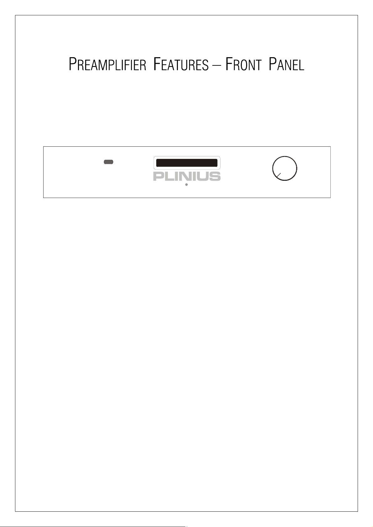
The front of the Plinius M8 Preamplifier.
Front Panel Layout Sho
Front Panel Layout Showing Volume Knob, Vacuum
Front Panel Layout ShoFront Panel Layout Sho
Fluorescent Display,
Fluorescent Display, And Display LED
Fluorescent Display, Fluorescent Display,
DI
DISPLAY LED
SPLAY LED
DIDI
SPLAY LEDSPLAY LED
An LED below ‘PLINIUS’ indicates when the preamplifier is in standby mode. This LED also lights to show
whenever the remote control is being used to change the volume level.
wing Volume Knob, Vacuum
wing Volume Knob, Vacuumwing Volume Knob, Vacuum
And Display LED
And Display LEDAnd Display LED
VACUU
VACUUM FLUORESCEN
VACUUVACUU
Whenever a modification is made to the M8 settings (via the remote control) these changes will be
viewable on the display.
VOLU
VOLUME CONTROL KNOB
VOLUVOLU
The volume control is an ALPS motorised unit that will accurately convey the selected source signal to the
line stage of the Plinius M8. When using the remote control to alter the volume level, briefly press the
button to make small adjustments, or hold the button down to continuously adjust the volume.
M FLUORESCENT DISPLAY
M FLUORESCENM FLUORESCEN
ME CONTROL KNOB
ME CONTROL KNOBME CONTROL KNOB
T DISPLAY
T DISPLAYT DISPLAY
6
Page 7
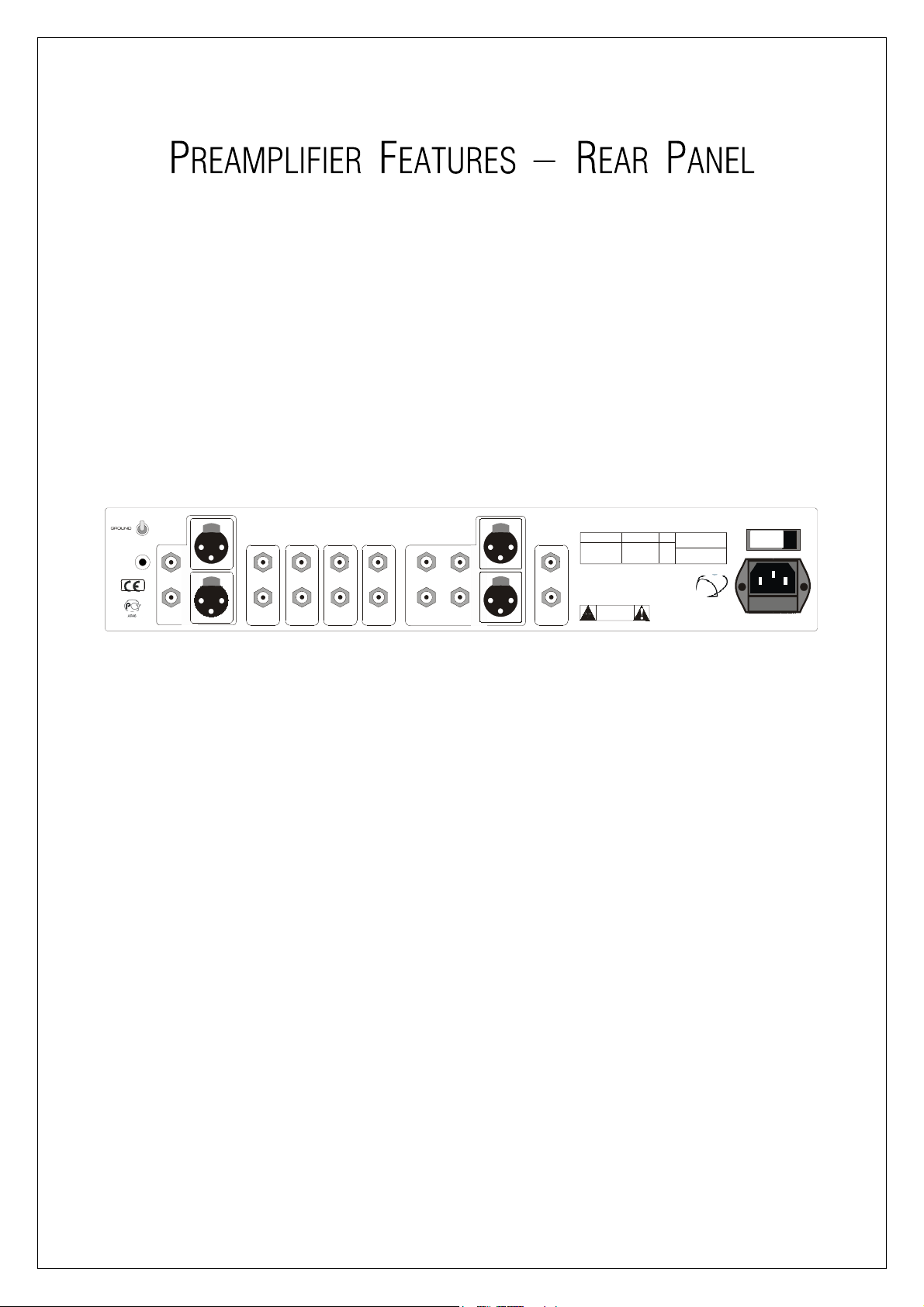
This panel incorporates all the terminals for connecting the input signals from your CD player, tuner, etc,
and the outputs to the power amp and mains supply.
Please remember that your Plinius M8 Preamplifier is a high quality electronic instrument capable of an
exceptional level of performance. Be sure that you understand your system’s requirements fully before
you make any connection to this preamplifier.
CHASSIS
LIFT
OPEN
INPUT TERMINAL
INPUT TERMINALSSSS
INPUT TERMINAL INPUT TERMINAL
PUSH
CD
PUSH
Rear Panel Showing In
Rear Panel Showing Input And Output Terminals
Rear Panel Showing InRear Panel Showing In
LINE 1 LINE 2 OUTPUTS
Lift Switch,
Lift Switch, Mains Switch
Lift Switch, Lift Switch,
LINE 4
LINE 3 PROCESSOR
put And Output Terminals, Ground
put And Output Terminalsput And Output Terminals
Mains Switch And Mains Sock
Mains Switch Mains Switch
PUSH
PUSH
And Mains Socket.
And Mains SockAnd Mains Sock
PLINIUS
M8
STEREO PREAMPLIFIER
SERIAL No. VOLTAGE Hz
DESIGNED AND MANU FACTURED IN
NEW ZEALAND BY
AUDIBLE TECHNOLOGIES LTD
P.O . BO X 183 6
PALM ERS TON N ORTH
CAUTION
RISK OF ELECTRICAL SHOCK
DO NOT OPEN
, Ground
, Ground, Ground
et.
et.et.
POWER
CONSUMPTION
50/
60
20VA
CAUTION:
TO REDUCE RISK OF
ELECTRICAL SHOCK DO NOT REMOVE
COVER. NO USER SERVICEABLE
PARTS INSIDE. REFER SERVICING TO
QUALIFIED SERVICE PERSONNEL.
ON / OFF
MAINS FUSE: REPLACE
ONLY WITH F5AL
The input terminals of your Plinius M8 Preamplifier are easily accessible along the rear panel. These
standard RCA terminals are for use with single ended signals from line level audio components such as
CD, tuner, surround processor, VCR, etc. Also included is one pair of balanced XLR inputs for use with
XLR type cables. Consult your PLINIUS
PLINIUS dealer for further advice if required.
PLINIUSPLINIUS
OUTPUT TERMIN
OUTPUT TERMINALS
OUTPUT TERMINOUTPUT TERMIN
ALS
ALSALS
Connections for power amplifiers are provided in the centre of the rear panel. Connections are available
for both single ended (RCA type) and balanced (XLR type) cables. Note that the only time the outputs
aren’t ‘live’ is when the preamplifier is in mute or standby.
7
Page 8

PROCESSOR INPU
PROCESSOR INPUTTTT
PROCESSOR INPUPROCESSOR INPU
This input is for use specifically with home theatre processors. In some circumstances you may wish to
use the power amplifier and speakers that the M8 is connected to as the front two channels of a surround
or home theatre environment. The processor input can be used for this purpose, as any signal connected
to the processor inputs can be sent directly to the power amplifier bypassing the M8 entirely.
GROUND LIFT S
GROUND LIFT SWITCH
GROUND LIFT SGROUND LIFT S
This switch allows the signal ground to be disconnected from the chassis. In some installations a hum
loop may exist due to duplicate ground paths from different equipment. Use this switch to remove the
connection from 0V to ground thus allowing some flexibility in your particular set-up.
MAINS SWITCH
MAINS SWITCH
MAINS SWITCHMAINS SWITCH
The heavy-duty rocker switch to the right of the panel turns the Mains/Line Power to the amplifier ON or
OFF. The amplifier draws a moderately high current when switched on, so it is not good practice to
rapidly turn the Mains switch on and off repeatedly.
WITCH
WITCHWITCH
MAINS P
MAINS POWER CORD IEC SOCKET
MAINS PMAINS P
This connector is where the mains supply cable from your wall connects to the preamplifier. A fuse
holder is mounted within this connection, and it holds a mains fuse to provide surge and overload
protection for your preamplifier.
EEEEARTH POST
ARTH POST
ARTH POSTARTH POST
This is a chassis connected gold-plated earth post for use with most vinyl turntables.
OWER CORD IEC SOCKET
OWER CORD IEC SOCKETOWER CORD IEC SOCKET
8
Page 9

VOLU
VOLUME CONTROL
ME CONTROL
VOLUVOLU
ME CONTROLME CONTROL
Use these two buttons to control the volume level of the preamplifier. The right side button increases
volume, while the left side button decreases the volume. Briefly press either button to make fine
adjustments to the volume level. Hold down either button to continually adjust the volume level.
MUTE
MUTE
MUTEMUTE
Pressing this button toggles the Plinius M8 in and out of mute.
PPPPHASE
HASE
HASEHASE
The phase of the input signal to the preamplifier is toggle from absolute to inverted 180° with each press
of this button.
STANDBY
STANDBY
STANDBYSTANDBY
Standby disconnects the outputs of the preamplifier and turns off the vacuum fluorescent display tube. It
is recommended that whenever the Plinius M8 is left switched on but not in use, the standby function be
activated to increase the life of the display tube.
DISP
DISPLAY
LAY
DISPDISP
LAYLAY
The display button on the remote enables you to quickly adjust the display brightness to either off or the
user set brightness level. If depressed once and the display brightness falls to zero, another press and the
display reverts to the current user preset level. This user level is set using the menu buttons on the
remote as described later in the ‘Settings Menu Structure’ section. Note that if the brightness is set to
zero, any button press will bring the brightness back to the current user setting so the screen can be read.
9
Page 10

SOURCE SELECTIO
SOURCE SELECTIONNNN
SOURCE SELECTIOSOURCE SELECTIO
The source selection buttons enable changing from one input to another when needed – either CD, Line 1,
Line 2, Line 3, or Line 4.
MENU ACCESS BUTTONS
MENU ACCESS BUTTONS
MENU ACCESS BUTTONSMENU ACCESS BUTTONS
The three buttons labelled Menu and Enter are used to set the M8 menu items. Use the Enter button to
access the menu, then the Up and Down buttons in conjunction with Enter to change settings as desired
(see the settings menu structure section following).
PROCESSOR INPUT SELECTION
PROCESSOR INPUT SELECTION
PROCESSOR INPUT SELECTIONPROCESSOR INPUT SELECTION
Press the Processor button to activate the processor bypass function, allowing a home theatre system to
directly access the front left and right channels of your system. The display will confirm selection of the
processor input by displaying ‘Proc’ for 3 seconds, after which the display reads ‘Processor’. At this time
standby, display and source are the only buttons that still function. To deselect the processor input press
any other source button on the remote control. Note that the processor input only works with the single
ended outputs – the balanced XLR outputs are not live when in processor mode.
10
Page 11

PL
PLACEMENT AND VENTILATION
ACEMENT AND VENTILATION
PLPL
ACEMENT AND VENTILATIONACEMENT AND VENTILATION
Ventilation through and around your Plinius M8 Preamplifier should be kept unimpeded, so ensure that
the heat vents (slots in the lid and base) are not covered or restricted in any way.
The Plinius M8 design incorporates a very high level of mechanical de-coupling of the input and output.
However, it can still be influenced by acoustical feedback in the operating environment. The use of
acoustic cones or a suitably spiked preamplifier stand or table, may further enhance the performance of
this preamplifier. Consult your PLINIUS
MAIN
MAINS VOLTAGE CONNECTION
S VOLTAGE CONNECTION
MAINMAIN
S VOLTAGE CONNECTIONS VOLTAGE CONNECTION
Firstly, check that the mains supply voltage printed on the rear of this preamplifier is similar to the mains
supply voltage in your area. If in doubt, please consult your PLINIUS
Mains supply power connection is via the supplied plug-in lead. A standard IEC socket connects the
mains power at the preamplifier end, while a local mains plug is required at the wall end.
The wiring code used inside all Plinius product is:
PLINIUS dealer for further advice if required.
PLINIUSPLINIUS
PLINIUS dealer.
PLINIUSPLINIUS
Green to Earth/Ground
Green to Earth/Ground
Green to Earth/GroundGreen to Earth/Ground
Blue to Neutral
Blue to Neutral
Blue to NeutralBlue to Neutral
Brown to Phase/Live
Brown to Phase/Live
Brown to Phase/LiveBrown to Phase/Live
Should a ‘local’ plug need fitting to the wall end of the lead, ensure that a suitably qualified service
technician wires the plug correctly.
IMPORTANT
IMPORTANT:
IMPORTANTIMPORTANT
: DO NOT POWER UP Y
: :
DO NOT POWER UP YOUR PREAMPLIFIER UNTIL YOU
DO NOT POWER UP YDO NOT POWER UP Y
CONNECTED YOUR INPUT/OUTPUT
CONNECTED YOUR INPUT/OUTPUTS CORRECTLY FOR YOUR
CONNECTED YOUR INPUT/OUTPUTCONNECTED YOUR INPUT/OUTPUT
SYSTEM, (AS EXPLAI
SYSTEM, (AS EXPLAINED IN THE NEXT SECTION).
SYSTEM, (AS EXPLAISYSTEM, (AS EXPLAI
OUR PREAMPLIFIER UNTIL YOU HAVE
OUR PREAMPLIFIER UNTIL YOU OUR PREAMPLIFIER UNTIL YOU
S CORRECTLY FOR YOUR
S CORRECTLY FOR YOURS CORRECTLY FOR YOUR
NED IN THE NEXT SECTION).
NED IN THE NEXT SECTION).NED IN THE NEXT SECTION).
HAVE
HAVEHAVE
11
Page 12

It is important that you connect your power amplifier/s (outputs) and source components (inputs) to your
Plinius M8 Preamplifier correctly to ensure the preamplifier is not damaged, and sounds its best within
your system. Now that you have read and familiarised yourself with the various connections on the
preamplifier, as covered in previous sections, we will describe in detail how to connect the preamplifier to
your system.
Connect your CD player, tuner, tape deck, etc, to the CD, Line1, Line 2, Line 3 or Line 4 RCA inputs on the
back of the Plinius M8. Make sure you connect the red coded cable to the red RIGHT RCA input, and the
black (or white) cable to the black LEFT RCA input. Also make sure the RCA connectors are a snug fit and
are inserted all the way in. If you are using balanced XLR cables note that only the CD input caters for this
type of connection. You will also need to use the settings menu and set the CD input to balanced (see
Settings Menu Structure following).
Next, connect your power amplifier/s cables to the output sockets. Ensure that you observe polarity on all
cables (red is right, black is left) to ensure correct channel phasing.
TE
TERMINATION QUALITY
RMINATION QUALITY
TETE
RMINATION QUALITYRMINATION QUALITY
Quality of the connections must be examined to ensure that high-performance, trouble-free operation is
enjoyed. Check that all interconnection cables are snug fitting and inserted all the way in. In the case of
balanced XLR sockets, ensure that they click in positively.
PHASING (OR POLARI
PHASING (OR POLARITY)
PHASING (OR POLARIPHASING (OR POLARI
It is important to achieve good stereo imaging in your listening room. By observing the wiring
instructions above, each preamplifier/power amplifier/loudspeaker combination should be in phase. If
you experience poor stereo image and/or a lack of bass, check that all interconnection cables and
loudspeaker wires have been connected correctly. We recommend that you use one of the easily
obtainable ‘test discs’ to help you ensure both phasing and channel orientation are correct. If in doubt,
consult your PLINIUS
Naturally it is also important to make sure all the leads carrying signals for the RIGHT channel loudspeaker
are connected to the RIGHT input to the amplifier from your preamplifier or CD player etc. Signals for the
LEFT channel should be wired in a similar fashion.
PLINIUS dealer for advice.
PLINIUSPLINIUS
TY)
TY)TY)
12
Page 13

CONNECTING THE
CONNECTING THE MAINS SUPPLY
CONNECTING THE CONNECTING THE
Now that your Plinius M8 Preamplifier is configured to your system correctly, the mains cable can be
plugged into the IEC socket on the back of the preamplifier. Re-check all interconnection cables are fitted
correctly. Turn on the power switch on the rear panel. The vacuum fluorescent display will now display
the messages ‘PLINIUS’, ‘M8’, ‘SERIAL NO XXXX’, while the internal circuitry stabilises. The preamplifier
will then close the mute circuit and set the active input to CD.
USING T
USING THE PROCESSOR INPU
USING TUSING T
By connecting two of the channel outputs of a home theatre processor to the M8 processor input
terminals, the M8 becomes a straight-through path for any signal that is connected to it. This enables the
M8 to remain in circuit for use with two channel sources (such as CD players and tuners), as well as a link
to the power amp and speakers should you wish to use your normal stereo set-up in a surround or home
theatre environment.
To access the processor input, press the Processor button on the remote control. To deselect the
processor input and return to using CD, Line 1, etc. as a source, press the source button you wish to listen
to. Note that when processor is selected, no other buttons or menu settings can be accessed, except
standby and display.
HE PROCESSOR INPUTTTT
HE PROCESSOR INPUHE PROCESSOR INPU
MAINS SUPPLY
MAINS SUPPLYMAINS SUPPLY
ENABLING THE INPUT
ENABLING THE INPUTS/OUTPUTS
ENABLING THE INPUTENABLING THE INPUT
Use the source buttons to select the input you want to listen to. Press the Mute button, then alter the
volume to achieve the sound level you require. The Phase button can be used to select absolute or
inverted 180° phase. If you wish to alter other settings such as CD input type, balance, or display
brightness, see the following section. You can now enjoy your new Plinius M8 Preamplifier.
WAR
WARM-UP PERIOD
M-UP PERIOD
WARWAR
M-UP PERIODM-UP PERIOD
You will find that the Plinius M8 will become noticeably ‘purer’ in sound after being on for a period of
time. We usually recommend waiting at least 24 hours before expecting the best quality of sound
reproduction from your preamplifier. Also, as the Plinius M8 uses very little power while on, we suggest
leaving the unit turned on (but in standby mode while not being used) so that it will always be at it’s sonic
best.
S/OUTPUTS
S/OUTPUTSS/OUTPUTS
13
Page 14

A major feature of your Plinius M8 Preamplifier is the settings menu. Options such as balance, display
brightness and CD input type are all configured via this menu.
USIN
USING THE SETTINGS MENU
G THE SETTINGS MENU
USINUSIN
G THE SETTINGS MENUG THE SETTINGS MENU
After pressing the Menu button on the remote, the settings menu can be accessed. The Down and Up
buttons can then be used to scroll through the following sub-menus:
Balance
Balance
BalanceBalance
Bypass
Bypass
BypassBypass
Display
Display
DisplayDisplay
CD Mode
CD Mode
CD ModeCD Mode
To enter any sub-menu listed above, press the Enter button. Adjust the settings of the sub-menu chosen
using the Down and Up buttons and when finished press Enter to return to the main display. The diagram
following is a visual reference of this system, and each sub-menu is described in detail below.
MEMO
MEMORY STORAGE OF SETTINGS
MEMOMEMO
The settings that you access below are all stored in the memory of the M8 microcontroller. Next time you
turn on the preamplifier, any settings you have changed (balance level, CD input type, display brightness
etc.) will be enabled in that same configuration.
RY STORAGE OF SETTINGS
RY STORAGE OF SETTINGSRY STORAGE OF SETTINGS
14
Page 15
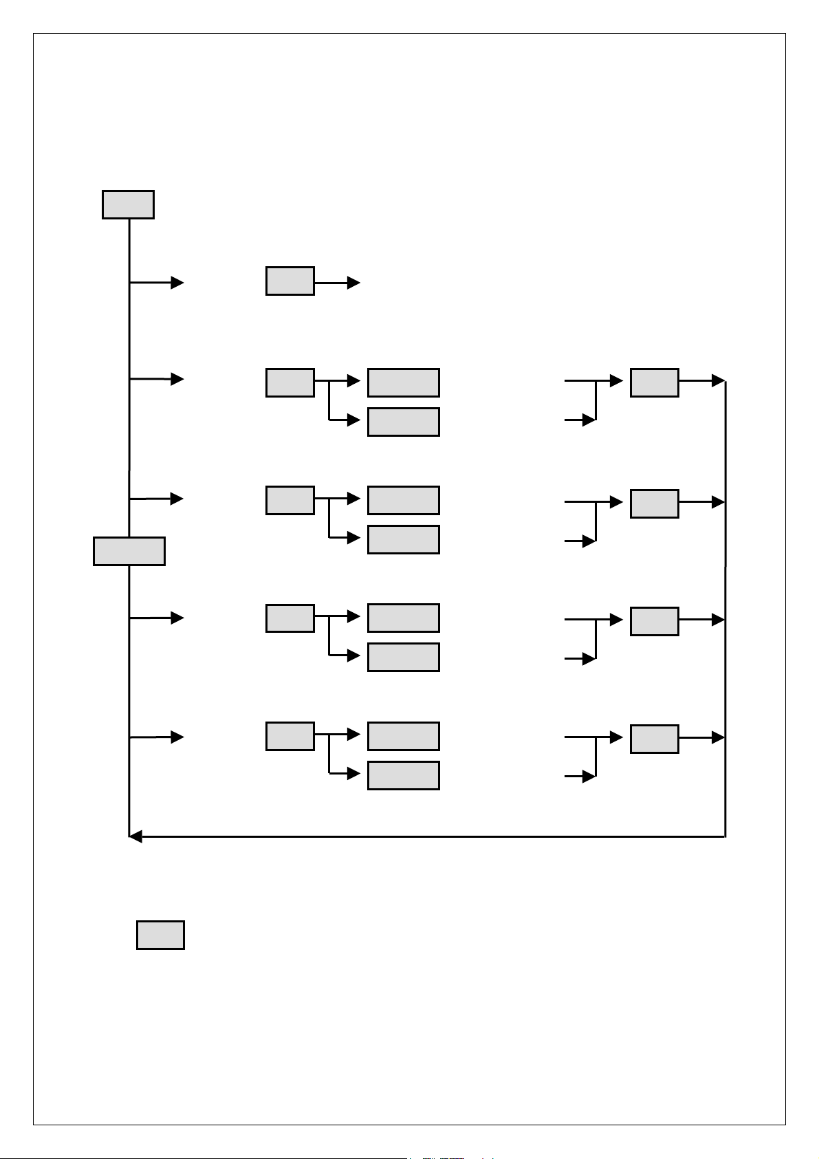
SETTINGS
p
p
SETTINGS MENU DIAGRAM
SETTINGS SETTINGS
Menu
MENU DIAGRAM
MENU DIAGRAMMENU DIAGRAM
Up/Down
EXIT M8 returns to Main Screen
BALANCE Balance Left -dB
BYPASS Balance Bypassed
DISPLAY Display Level 31
Enter
Enter
Enter
Enter
U
Down
Up/Down
Up/Down
U
Down
Balance Right -dB
Balance Enabled
Display Level 1
Enter
Enter
Enter
CD MODE CD Single Ended
Enter
Up/Down
Up/Down
Enter
CD Balanced
Denotes a button press
Up or Down can be held down to perform repetitive key presses
Press and hold Up and Down together within Balance sub-menu to return to centre position
After 15 seconds of inactivity in any sub-menu the preamplifier will return to the Main Screen
If the preamplifier does auto exit the menu system, your settings are not saved
15
Page 16

EXI
EXIT SUB-MENU
T SUB-MENU
EXIEXI
T SUB-MENUT SUB-MENU
When ‘Exit’ appears on the display, press Enter to return the preamplifier to the main screen from the
settings menu.
BALANCE SUB-MENU
BALANCE SUB-MENU
BALANCE SUB-MENUBALANCE SUB-MENU
Press Enter and you can now use the Down and Up buttons to vary the signal between the right and left
channels. Note that if you depress the Up button the signal to the left channel is reduced as denoted by
the screen message. The opposite applies when using the Down button. Pressing and holding both Down
and Up buttons will return the balance level to centre. Holding either Down or Up will enable fast
scrolling through the balance levels. Use Enter to exit this sub-menu. You can also remove the balance
control circuitry from the signal path by using the Bypass sub-menu explained below.
BBBBYPASS SUB-MENU
YPASS SUB-MENU
YPASS SUB-MENUYPASS SUB-MENU
To remove the balance control press Enter and use Down or Up to toggle the balance circuitry on or off.
Press Enter once your selection has been made to exit the sub-menu.
DDDDISPLAY SUB-MENU
ISPLAY SUB-MENU
ISPLAY SUB-MENUISPLAY SUB-MENU
Press Enter and the display sub-menu will allow you to vary the display brightness to suit the lighting in
your room. Use Down or Up to vary the brightness from 1 to 31 (31 being the brightest). Once a suitable
brightness level has been achieved, press Enter to return to the main display. Note that as with the
balance control you may hold Up or Down to quickly scroll through the brightness levels. Should you
choose a brightness level below 5 and turn off the M8, the preamplifier will power up again at 5 to ensure
you can always restart your preamplifier and change settings should you accidentally set the brightness
too low to read.
CD MODE SUB-MENU
CD MODE SUB-MENU
CD MODE SUB-MENUCD MODE SUB-MENU
If you wish to change CD input from single ended (RCA) to balanced (XLR) press Enter to access the CD
mode sub-menu, then Down or Up to toggle between the two options. Press Enter once your selection
has been made to exit the sub-menu.
16
Page 17

REMOTE CONTROL
REMOTE CONTROL
REMOTE CONTROLREMOTE CONTROL
Provided with your Plinius M8 is a 15 function remote control. Two AAA batteries power the remote, and
these are replaced by removing the two posi-drive screws on the rear face of the remote that hold the
battery compartment in place. The bottom end of the remote is now free to slide down for access to the
batteries. Replace the two batteries, taking care to refit the new ones with correct polarity.
MAINS
MAINS/LINE FUSE
MAINSMAINS
A Mains/Line fuse is fitted within the IEC socket on the rear of the preamplifier. A small drawer at the
bottom of this socket may be removed (after the IEC plug is removed) by levering it out with a flat blade
screwdriver. The fuse fitted should be rated at no greater than 5 amps normal blow.
IMPORTANT
IMPORTANT:
IMPORTANTIMPORTANT
In the unusual event that this fuse should blow, you must first establish the cause of this failure (such as
power surges, damaged mains cable, etc.) before replacing the fuse with one of the same rating and type.
Should the preamplifier continue to suffer mains fuse failure, contact your PLINIUS
/LINE FUSE
/LINE FUSE/LINE FUSE
: DO NOT
: :
DO NOT FIT A FUSE WITH A HIGHER RATING.
DO NOT DO NOT
FIT A FUSE WITH A HIGHER RATING.
FIT A FUSE WITH A HIGHER RATING.FIT A FUSE WITH A HIGHER RATING.
PLINIUS dealer.
PLINIUSPLINIUS
17
Page 18

S F
FREQUENCY
REQUENCY R
REQUENCY REQUENCY
FF
S D
DISTORTION
ISTORTION: Typically <0.05% THD at rated input level.
ISTORTIONISTORTION
DD
S H
HUM
UM & N
UM UM
HH
S I
INPUT
NPUT S
NPUT NPUT
II
S I
INPUT
NPUT I
NPUT NPUT
II
S R
RATED
ATED O
ATED ATED
RR
S O
OUTPUT
UTPUT S
UTPUT UTPUT
OO
S H
HEIGHT
EIGHT:
EIGHTEIGHT
HH
RESPONSE
ESPONSE:
ESPONSEESPONSE
RR
& NOISE
OISE:
: -80dB at rated input level, A Weighted.
OISEOISE
& N& N
SENSITIVITY
SS
IMPEDANCE
II
::
ENSITIVITY F
ENSITIVITY ENSITIVITY
MPEDANCE:
MPEDANCEMPEDANCE
OUTPUT
UTPUT L
UTPUT UTPUT
OO
SOURCE
OURCE I
OURCE OURCE
SS
: 90mm (3 1/2")
: :
FOR
OR R
OR OR
FF
: 50kΩ.
: :
LEVEL
EVEL:
: 500mV RMS into 10kΩ or higher.
EVELEVEL
LL
: :
IMPEDANCE
MPEDANCE:
MPEDANCEMPEDANCE
II
: 20Hz to 20kHz ±0.2dB.
::
RATED
ATED O
OUTPUT
UTPUT:
ATED ATED
RR
OO
: Typically 100Ω.
: :
: 125mV RMS unbalanced inputs. 62mV RMS balanced input.
UTPUTUTPUT
::
S WWWWIDTH
S DDDDEPTH
S W
IDTH:
IDTHIDTH
EPTH:
EPTHEPTH
WEIGHT
EIGHT:
EIGHTEIGHT
WW
: 450mm (17 3/4")
: :
: 400mm (15 3/4")
: :
: 5.5kg (12lbs)
: :
18
Page 19

Balance Control..................................................................................................................... Pages 10,16
Date of Manufacture .......................................................................................................................Page 3
Display LED ...................................................................................................................................Page 6
Front Panel Layout..........................................................................................................................Page 6
Fuse Protection ............................................................................................................................Page 17
Ground Lift Switch..........................................................................................................................Page 8
IEC Power Connector............................................................................................................... Pages 8,11
Input Terminals .......................................................................................................................Pages 7,12
Mains/Line Fuse...........................................................................................................................Page 17
Mains Supply Connection.............................................................................................................Page 13
Mains Switch .................................................................................................................................Page 8
Menu Controls ......................................................................................................................Pages 14,16
Menu Diagram .............................................................................................................................Page 15
Output Terminals.....................................................................................................................Pages 7,12
Phasing........................................................................................................................................Page 12
Placement...............................................................................................................................Pages 5,11
Rear Panel Layout...........................................................................................................................Page 7
Remote Control ....................................................................................................................... Pages 9,17
Safety Precautions..........................................................................................................................Page 5
Serial Number................................................................................................................................Page 3
Settings Storage...........................................................................................................................Page 14
Standby Function ..................................................................................................................Pages 10,16
Terminations ................................................................................................................................Page 12
Vacuum Fluorescent Display...........................................................................................................Page 6
Ventilation....................................................................................................................................Page 11
Volume Control ......................................................................................................................... Pages 7,9
Warm-Up Period ..........................................................................................................................Page 13
XLR Connections.....................................................................................................................Pages 7,16
19
Page 20

All operational, technical and descriptive material published here is subject to change at any time without
notice. For further product information or queries, please contact us at the address below.
PLINIUS
PLINIUS products are designed and manufactured by:
PLINIUSPLINIUS
Audible Technologies Ltd.
Audible Technologies Ltd.
Audible Technologies Ltd.Audible Technologies Ltd.
P.O. Box 18
P.O. Box 1836
P.O. Box 18P.O. Box 18
Palmerston North
Palmerston North
Palmerston NorthPalmerston North
New Zealand
New Zealand
New ZealandNew Zealand
Phone:
Phone: 64 6 354 8583
Phone:Phone:
Facsimile:
Facsimile: 64 6 354 8586
Facsimile:Facsimile:
36
3636
Email:
Email: [email protected]
Email:Email:
Internet:
Internet: www.pliniusaudio.com
Internet:Internet:
©2003 Audible Technologies.
20
 Loading...