

Page 1

Page 2

2
Page 3

CONGRATULATIONS
CONGRATULATIONS on your decision to become the proud owner of this
CONGRATULATIONSCONGRATULATIONS
Plinius 9100 Integrated Amplifier.
This manual has been prepared to help you understand the operation of your amplifier, and to provide
information about its design and the variety of ways it may be used.
We have designed and manufactured this amplifier to reproduce faithfully and accurately, your favourite
music. With a little care and a full understanding of the operating recommendations in this manual, your
Plinius 9100 Integrated Amplifier will provide years of high-quality, trouble-free performance.
Serial Number: ..................................................................................
Date of Manufacture: ..................................................................................
Final Test Certified By: ..................................................................................
IMPORTANT
IMPORTANT::::P
IMPORTANTIMPORTANT
PLEASE TAKE THE TIME TO READ THIS MANUAL
LEASE TAKE THE TIME TO READ THIS MANUAL
PP
LEASE TAKE THE TIME TO READ THIS MANUALLEASE TAKE THE TIME TO READ THIS MANUAL
THOROU
THOROUGHLY BEFORE USING YOUR AM
THOROUTHOROU
GHLY BEFORE USING YOUR AMPLIFIER.
GHLY BEFORE USING YOUR AMGHLY BEFORE USING YOUR AM
PLIFIER.
PLIFIER.PLIFIER.
3
Page 4

Introduction ...................................................................................................................................Page 3
Precautions ...................................................................................................................................Page 5
Amplifier Features – Front Panel ..................................................................................................Page 6
Amplifier Features – Rear Panel ...................................................................................................Page 7
Installation and Operation ..............................................................................................................Page 9
Input/Output Connection ..............................................................................................................Page 10
9100 Features .............................................................................................................................Page 12
Loudspeaker Selection ................................................................................................................Page 14
Specifications .............................................................................................................................Page 15
Index ...........................................................................................................................................Page 16
Contact Details ............................................................................................................................Page 17
4
Page 5

Please take special note of the following precautions before operating your new amplifier:
• The Plinius 9100 Integrated Amplifier can deliver in excess of 120 watts into 8 ohms. This
amplifier is also capable of a very large peak current delivery.
• The Plinius 9100 Integrated Amplifier operates in Class AB. It is capable of generating heat that
could have an adverse effect on other electronic equipment, furniture, etc. DO NOT leave
flammable material on the amplifier whilst running, as this could pose a serious fire risk.
• This amplifier operates at hazardous voltage levels. There are some alterations that may be made
by you, the owner. However, we recommend that any work requiring removal of the lid be referred
to a suitably qualified and experienced service technician.
• DO NOT attempt to connect any input of this amplifier to its own outputs.
• DO NOT earth any output terminal or connect any of these terminals together without following the
instructions in this manual or seeking qualified assistance.
• DO NOT place this amplifier in any position where liquids, or any foreign material may accidentally
enter it.
• DO NOT connect any voltage source, short circuit, earth/ground or appliance (other than suitable
high fidelity loudspeakers) to the amplifier output terminals.
5
Page 6
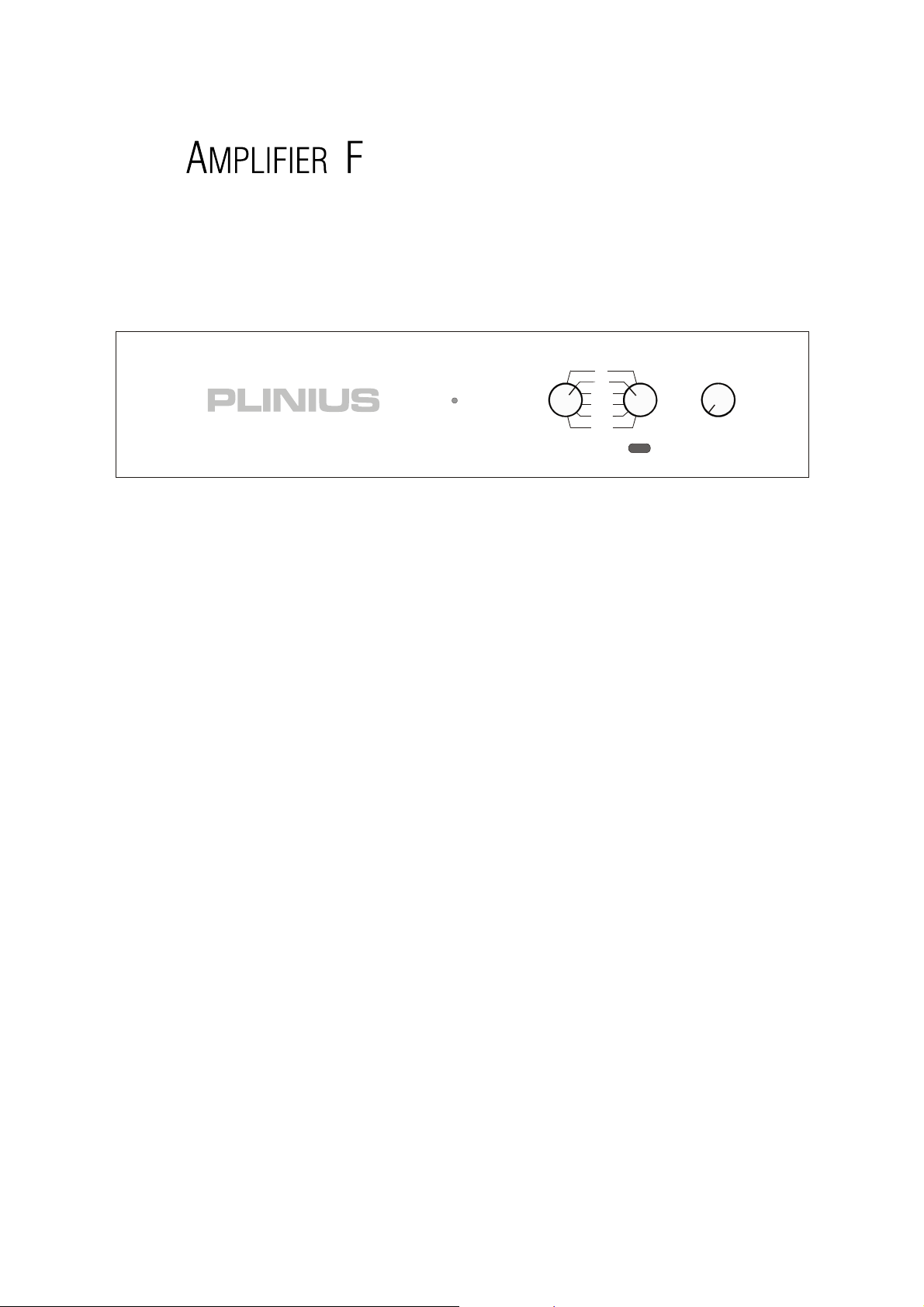
RECORD SOURCE VOLUME
VCRT
AUX
TUNER
APE 1
TAP E 2
CD
xxx
6
Page 7

7
Page 8

TAPE OUTPUTS
TAPE OUTPUTS
TAPE OUTPUTSTAPE OUTPUTS
These RCA outputs are situated next to the tape RCA inputs, and are provided to interface to a pair of line
level recording devices. The position of the record selector on the front panel determines from which
device a recording is being made. As these tape outputs are always ‘live’, both can be used to record the
chosen signal at any time.
MUTE S
MUTE SWITCH
MUTE SMUTE S
The mute switch enables disconnection of the output, without the need to use the remote control. When
the amplifier is in mute, the LED on the front panel will dim.
GROUN
GROUND LIFT SWITCH
GROUNGROUN
This switch allows the signal ground to be disconnected from the chassis. In some installations a hum
loop may exist due to duplicate ground paths from different equipment. Use this switch to remove the
connection from 0V to ground thus allowing some flexibility in your particular set-up.
WITCH
WITCHWITCH
D LIFT SWITCH
D LIFT SWITCHD LIFT SWITCH
PR
PRE OUT OUTPUT
E OUT OUTPUT
PRPR
E OUT OUTPUTE OUT OUTPUT
The Pre-Out connection is provided to enable the Plinius 9100 to be connected to an external power
amplifier. The signal from this output is line level, and as such is not amplified by the power stage of the
Plinius 9100.
MAINS PO
MAINS POWER CORD IEC SOCKET
MAINS POMAINS PO
This connector is where the mains supply cable from your wall connects to the amplifier. You will notice
that a fuse holder is mounted within this connection, and it holds a mains fuse to provide surge and
overload protection for your amplifier.
RRRRAIL FUSES
AIL FUSES
AIL FUSESAIL FUSES
These tubular fuse holders house the positive and negative rail protection fuses. Depress and turn anticlockwise to open. An LED is fitted next to each fuse holder to indicate a blown fuse.
WER CORD IEC SOCKET
WER CORD IEC SOCKETWER CORD IEC SOCKET
8
Page 9

PLACEMEN
PLACEMENT AND VENTILATION
PLACEMENPLACEMEN
Your Plinius 9100 may operate at a moderately high temperature when being driven hard. The ideal
location is upon a rigid stand, or floor mounted away from direct contact with any temperature sensitive
materials or deep pile carpets. Ventilation through and around the amplifier should also be kept
unimpeded, so ensure that the heat vents (slots in the lid and base) are not covered or restricted in any
way.
The Plinius 9100 design incorporates a very high level of mechanical de-coupling of the input and output.
It can however still be influenced by acoustical feedback in the operating environment. The use of
acoustic cones, or a suitably spiked amplifier stand or table, may further enhance the performance of this
amplifier. Consult your PLINIUS
MAINS VOLTA
MAINS VOLTAGE CONNECTION
MAINS VOLTAMAINS VOLTA
Firstly, check that the mains supply voltage printed on the rear of this amplifier is similar to the mains
supply voltage in your area. If in doubt, please consult your PLINIUS
T AND VENTILATION
T AND VENTILATIONT AND VENTILATION
PLINIUS dealer for further advice if required.
PLINIUSPLINIUS
GE CONNECTION
GE CONNECTIONGE CONNECTION
PLINIUS dealer.
PLINIUSPLINIUS
Mains supply power connection is via the supplied plug-in lead. A standard IEC socket connects the
mains power at the amplifier end, while a local mains plug is required at the wall end.
The wiring code used inside all Plinius product is:
Green to Earth/Ground
Green to Earth/Ground
Green to Earth/GroundGreen to Earth/Ground
Blue to Neutral
Blue to Neutral
Blue to NeutralBlue to Neutral
Brown to Phase/Live
Brown to Phase/Live
Brown to Phase/LiveBrown to Phase/Live
Should a ‘local’ plug need fitting to the wall end of the lead, ensure that a suitably qualified service
technician wires the plug correctly.
IMPORTANT
IMPORTANT:
IMPORTANTIMPORTANT
: DO NOT POWER UP YOUR AMPL
: :
DO NOT POWER UP YOUR AMPLIFIER UNTIL YOU
DO NOT POWER UP YOUR AMPLDO NOT POWER UP YOUR AMPL
YOUR INPUT/OUTPUT
YOUR INPUT/OUTPUTS CORRECTLY FOR YOUR SYSTEM, (AS
YOUR INPUT/OUTPUTYOUR INPUT/OUTPUT
EXPLAI
EXPLAINED IN THE NEXT SECTION).
EXPLAIEXPLAI
NED IN THE NEXT SECTION).
NED IN THE NEXT SECTION).NED IN THE NEXT SECTION).
S CORRECTLY FOR YOUR SYSTEM, (AS
S CORRECTLY FOR YOUR SYSTEM, (ASS CORRECTLY FOR YOUR SYSTEM, (AS
IFIER UNTIL YOU HAVE CONNECTED
IFIER UNTIL YOU IFIER UNTIL YOU
HAVE CONNECTED
HAVE CONNECTEDHAVE CONNECTED
9
Page 10

It is important that you connect your loudspeakers (outputs) and source components (inputs) to the
Plinius 9100 Integrated Amplifier correctly to ensure the amplifier is not damaged, and sounds its best
with your system. Now that you have read and familiarised yourself with the connections on the back of
the amplifier, as covered in the previous section, we will describe in detail the way in which you can
connect the amplifier to your system.
Connect your tuner, CD player, tape decks, etc, to the corresponding RCA inputs on the back of the
Plinius 9100. Make sure you connect the red coded cable to the red RIGHT RCA input, and the black (or
white) cable to the black LEFT RCA input. Also make sure the RCA connectors are a snug fit and are
inserted all the way in.
Next, connect your loudspeaker wires to the output posts. Connect your right loudspeaker (i.e. the one on
the right of you when seated in your normal listening position) to the right output terminals, ensuring that
the red positive (+) terminal is connected to the red terminal on your loudspeaker. Do the same with the
black or negative (-) terminals.
RECORDING M
RECORDING MUSIC
RECORDING MRECORDING M
In order to record music to tape, or some other line level recording device, these devices will need to be
connected to the tape 1 and tape 2 outputs. Turn the record selector on the front panel to the input you
wish to record from, and the amplifier will now send signal to both tape 1 and tape 2 outputs. Note that
the volume control does not adjust the recording level - this is done at the recording device itself.
USIC
USICUSIC
USING PRE OUT
USING PRE OUT
USING PRE OUTUSING PRE OUT
A line level output is provided on the back of the Plinius 9100. If you wish to use the Plinius 9100 as a
pre-amp only, or to send signal to another amplifier, fit the interconnect cable to the pre out outputs. Note
that the pre out connections provide signal from whatever the source selector knob is currently set to.
LOUDSPEAKER TER
LOUDSPEAKER TERMINATION QUALITY
LOUDSPEAKER TERLOUDSPEAKER TER
Quality of the connections must be examined to ensure that high-performance, trouble-free operation is
enjoyed. Check that the connections are tight but do not over tighten. If bare wires are used make sure
that no loose strands of wire short across the other terminals or the amplifier chassis. When using plugs
such as bananas, be sure to use good quality plugs with a firm fit.
MINATION QUALITY
MINATION QUALITYMINATION QUALITY
10
Page 11

BI-
BI-WIRING
WIRING
BI-BI-
WIRINGWIRING
Bi-wiring uses two pairs of loudspeaker cables for each channel loudspeaker. You will notice that the rear
panel of your Plinius 9100 has two pairs of output terminals for this purpose. When using bi-wires,
always connect positive (+) to positive (+) and the same for the negative (-) terminals.
PHASING (
PHASING (OR POLARITY)
PHASING (PHASING (
It is important to achieve good stereo imaging in your listening room. By observing the wiring
instructions above, each power amplifier/loudspeaker combination should be in phase. If you experience
poor stereo image and/or a lack of bass, check that the loudspeaker wiring has been connected correctly.
We recommend that you use one of the easily obtainable ‘test discs’ to help you ensure both phasing and
channel orientation are correct. If in doubt, consult your PLINIUS
Naturally it is also important to make sure all the leads carrying signals for the RIGHT channel loudspeaker
are connected to the RIGHT input to the amplifier from your preamplifier or CD player etc. Signals for the
LEFT channel should be wired in a similar fashion.
OR POLARITY)
OR POLARITY)OR POLARITY)
PLINIUS dealer for advice.
PLINIUSPLINIUS
CONN
CONNECTING THE MAINS S
CONNCONN
Now that your Plinius 9100 Integrated Amplifier is configured correctly, the mains cable can be plugged
into the IEC socket on the back of the amplifier. Re-check the speaker cables are connected correctly.
Turn on the power switch on the rear panel. The display LED will pulsate for ten seconds as the internal
microprocessor allows the internal circuitry to stabilise before opening the mute circuit. You can now
enjoy your new Plinius 9100 Integrated Amplifier.
WARM-UP PERI
WARM-UP PERIOD
WARM-UP PERIWARM-UP PERI
ECTING THE MAINS SUPPLY
ECTING THE MAINS SECTING THE MAINS S
OD
ODOD
UPPLY
UPPLYUPPLY
11
Page 12

REMOTE CONTROL
REMOTE CONTROL
REMOTE CONTROLREMOTE CONTROL
Provided with your Plinius 9100 is a three function remote control. The two buttons at the top of the
remote adjust the volume level, and the button below switches the amplifier in and out of mute. Two AAA
batteries power the remote, and these are replaced by removing the two posi-drive screws on the rear face
of the remote that hold the battery compartment in place. The bottom end of the remote is now free to
slide down for access to the batteries. Replace the two batteries, taking care to refit the new ones with
correct polarity.
TA
TAPE LOCKOUT PROTECTION
PE LOCKOUT PROTECTION
TATA
PE LOCKOUT PROTECTIONPE LOCKOUT PROTECTION
On most tape decks, any signal recorded is sent to the tape outputs so that the signal level of the
recording can be monitored. Should the user accidentally try to record the tape decks own output,
feedback howl usually results. The Plinius 9100 Tape Lockout feature prevents this situation from
damaging your system speakers by muting the power amplifier.
FUSE PROTECTION
FUSE PROTECTION
FUSE PROTECTIONFUSE PROTECTION
When any rail fuse is damaged one or more fuse warning LED’s will light. These LED’s are located next to
the fuse that has blown. To replace the fuse, steady the amplifier, then firmly push in the round fuse cap
with your fingers. When the cap cannot push in any further, rotate the cap anticlockwise (to the left) until
it comes to a stop. Release inward pressure on the fuse cap and it can now be removed from the
amplifier. If any of the rail fuses need to be replaced, do so only with 5 amp normal blow fuses.
To re-fit the fuse, insert the fuse and gently turn it as far as possible anticlockwise (to the left). Now push
the fuse cap in firmly, then turn clockwise (to the right) until it comes to a stop. Release inward pressure
on the cap and the fuse will be fitted securely.
IMPORTANT
IMPORTANT:::: DO NOT
IMPORTANTIMPORTANT
Note that fuse failure may indicate a severe problem. Check all speakers and speaker cables for
damage/short circuit, etc. Should the amplifier continue to suffer rail fuse failure, contact your PLINIUS
dealer.
DO NOT FIT A FUSE WITH A HIGHER RATING.
DO NOT DO NOT
FIT A FUSE WITH A HIGHER RATING.
FIT A FUSE WITH A HIGHER RATING.FIT A FUSE WITH A HIGHER RATING.
PLINIUS
PLINIUSPLINIUS
12
Page 13

MAINS/LINE FUSE
MAINS/LINE FUSE
MAINS/LINE FUSEMAINS/LINE FUSE
A Mains/Line fuse is fitted within the IEC socket on the rear of the amplifier. A small drawer at the bottom
of this socket may be removed (after the IEC plug is removed) by levering it out with a flat blade
screwdriver. The fuse fitted should be rated at no greater than 5 amps slow blow.
IMPORTANT
IMPORTANT:
IMPORTANTIMPORTANT
In the unusual event that this fuse should blow, you must first establish the cause of this failure (such as
power surges, damaged mains cable, etc.) before replacing the fuse with one of the same rating and type.
Should the amplifier continue to suffer mains fuse failure, contact your PLINIUS
: DO NOT FIT A FUSE WITH A HIGHER RATING.
: :
DO NOT FIT A FUSE WITH A HIGHER RATING.
DO NOT FIT A FUSE WITH A HIGHER RATING.DO NOT FIT A FUSE WITH A HIGHER RATING.
PLINIUS dealer.
PLINIUSPLINIUS
13
Page 14

Your Plinius 9100 Integrated Amplifier is designed for use with high fidelity loudspeakers. It should not
be used to operate with any other type of appliance or equipment.
Choice of loudspeakers is one of personal taste, providing the chosen loudspeakers are suitable for use
with your amplifier. Be certain that your loudspeakers can handle most of the rated output power of this
amplifier. You may find loudspeaker specifications confusing or misleading, so you should discuss this
with your audio dealer prior to purchase. As a general rule, the use of high power (200 Watt RMS or
greater) loudspeakers is recommended and desirable. However, our experience indicates that medium to
low power loudspeakers (100 to 200 Watt RMS) are quite often suitable for use on this amplifier, provided
the volume is maintained at a level where no distortion is audible.
Impedance of the loudspeaker load is important to ensure the rated performance of this amplifier. Any
combination of loudspeakers may be used, but the total average impedance load for each channel should
be within a range of 4 to 8 ohms. Again, if you have doubts about the impedance of your loudspeaker
configuration, we recommend you speak to your PLINIUS
PLINIUS dealer.
PLINIUSPLINIUS
14
Page 15

111120-WATTS RMS PER
20-WATTS RMS PER CHANNEL INT
20-WATTS RMS PER 20-WATTS RMS PER
BOTH CHANNELS DRI
BOTH CHANNELS DRIVEN FROM 20Hz TO 20kHz AT LE
BOTH CHANNELS DRIBOTH CHANNELS DRI
DISTORTION.
DISTORTION.
DISTORTION.DISTORTION.
S F
FREQUENCY
REQUENCY R
REQUENCY REQUENCY
FF
S D
DISTORTION
ISTORTION: Typically <0.05% THD at rated power. 0.1% THD and IM worst case prior to clipping.
ISTORTIONISTORTION
DD
S CCCCURRENT
URRENT O
URRENT URRENT
S S
SLEWING
LEWING:
LEWINGLEWING
SS
S H
HUM
UM & N
UM UM
HH
S I
INPUT
NPUT S
NPUT NPUT
II
S I
INPUT
NPUT I
NPUT NPUT
II
S I
INPUT
NPUT O
NPUT NPUT
II
RESPONSE
ESPONSE:
ESPONSEESPONSE
RR
OUTPUT
UTPUT:
UTPUTUTPUT
OO
: 50V/µs.
::
& NOISE
OISE:
: 90dB below rated output 20Hz to 20kHz unweighted.
OISEOISE
& N& N
SENSITIVITY
SS
IMPEDANCE
II
OVERLOAD
OO
::
ENSITIVITY:
ENSITIVITYENSITIVITY
MPEDANCE:
MPEDANCEMPEDANCE
VERLOAD:
VERLOADVERLOAD
CHANNEL INTO 8 OHMS.
CHANNEL INTCHANNEL INT
VEN FROM 20Hz TO 20kHz AT LESS THAN 0.2% TOTAL HARMONIC
VEN FROM 20Hz TO 20kHz AT LEVEN FROM 20Hz TO 20kHz AT LE
: 20Hz to 20kHz ±0.2dB. 0dB at 0Hz and -3dB at 70kHz.
::
: 20A short duration peak per channel. Fuse protected.
::
: 290mV RMS for rated output at 1kHz.
::
: 47kΩ.
: :
: 5V RMS.
::
O 8 OHMS.
O 8 OHMS.O 8 OHMS.
SS THAN 0.2% TOTAL HARMONIC
SS THAN 0.2% TOTAL HARMONICSS THAN 0.2% TOTAL HARMONIC
S R
RATED
RR
S P
PRE
PP
PPPPRE
S
S T
TAPE
TT
S
HHHHEIGHT
S W
WIDTH
WW
S D
DEPTH
DD
S W
WEIGHT
WW
ATED P
PRE
RE O
OUT
UT L
ATED ATED
RE RE
PP
RE O
OUT
UT S
RE RE
UT UT
OO
RE O
OUT
UT M
RE RE
UT UT
OO
APE O
OUTPUT
UTPUT L
APE APE
UTPUT UTPUT
OO
EIGHT:
: 105mm (4")
EIGHTEIGHT
: :
IDTH:
: 450mm (17 3/4")
IDTHIDTH
: :
EPTH:
: 400mm (15 3/4")
EPTHEPTH
: :
EIGHT:
: 10kg (22lbs)
EIGHTEIGHT
: :
LEVEL
UT UT
OO
LL
SOURCE
OURCE I
OURCE OURCE
SS
MINIMUM
INIMUM R
INIMUM INIMUM
MM
LEVEL
EVEL:
EVELEVEL
LL
EVEL:
: 1.5V RMS into 47kΩ or higher.
EVELEVEL
: :
IMPEDANCE
MPEDANCE:
MPEDANCEMPEDANCE
II
RECOMMENDED
ECOMMENDED L
ECOMMENDED ECOMMENDED
RR
: Unity Gain at 200Ω. Tape loop muting at 5V RMS input.
: :
: Typically 1.5kΩ.
: :
LOAD
OAD:
: 47kΩ.
OADOAD
LL
: :
15
Page 16

Bi-wiring......................................................................................................................................Page 11
Date of Manufacture .......................................................................................................................Page 3
Front Panel Layout..........................................................................................................................Page 6
Fuse Protection ............................................................................................................................Page 12
Ground Lift Switch..........................................................................................................................Page 8
IEC Power Connector............................................................................................................... Pages 9,12
Input Terminals .......................................................................................................................Pages 7,10
Loudspeaker Impedance...............................................................................................................Page 14
Loudspeaker Power ......................................................................................................................Page 14
Mains/Line Fuse...........................................................................................................................Page 13
Mains Supply Connection.............................................................................................................Page 11
Mains Switch .................................................................................................................................Page 7
Mute Switch...................................................................................................................................Page 8
Operating Temperature .............................................................................................................Pages 5, 9
Output Terminals.....................................................................................................................Pages 8,10
Phasing........................................................................................................................................Page 11
Placement.................................................................................................................................Pages 5,9
Pre Out Output.........................................................................................................................Pages 8,10
Rail Fuses ...............................................................................................................................Pages 8,12
Rear Panel Layout...........................................................................................................................Page 7
Record Selector .............................................................................................................................Page 6
Remote Control ............................................................................................................................Page 12
Safety Precautions..........................................................................................................................Page 5
Serial Number................................................................................................................................Page 3
Source Selector..............................................................................................................................Page 6
Tape Outputs..................................................................................................................................Page 8
Tape Lockout................................................................................................................................Page 12
Terminations ................................................................................................................................Page 10
Ventilation.................................................................................................................................Pages 5,9
Volume Control ..............................................................................................................................Page 6
Warm-Up Period ..........................................................................................................................Page 11
16
Page 17

All operational, technical and descriptive material published here is subject to change at any time without
notice. For further product information or queries, please contact us at the address below.
PLINIUS
PLINIUS products are designed and manufactured by:
PLINIUSPLINIUS
Audible Technologies Ltd.
Audible Technologies Ltd.
Audible Technologies Ltd.Audible Technologies Ltd.
P.O. Box 18
P.O. Box 1836
P.O. Box 18P.O. Box 18
Palmerston North
Palmerston North
Palmerston NorthPalmerston North
New Zealand
New Zealand
New ZealandNew Zealand
Phone:
Phone: 64 6 354 8583
Phone:Phone:
Facsimile:
Facsimile: 64 6 354 8586
Facsimile:Facsimile:
36
3636
Email:
Email: [email protected]
Email:Email:
Internet:
Internet: www.pliniusaudio.com
Internet:Internet:
©2003 Audible Technologies.
17
 Loading...