

Page 1
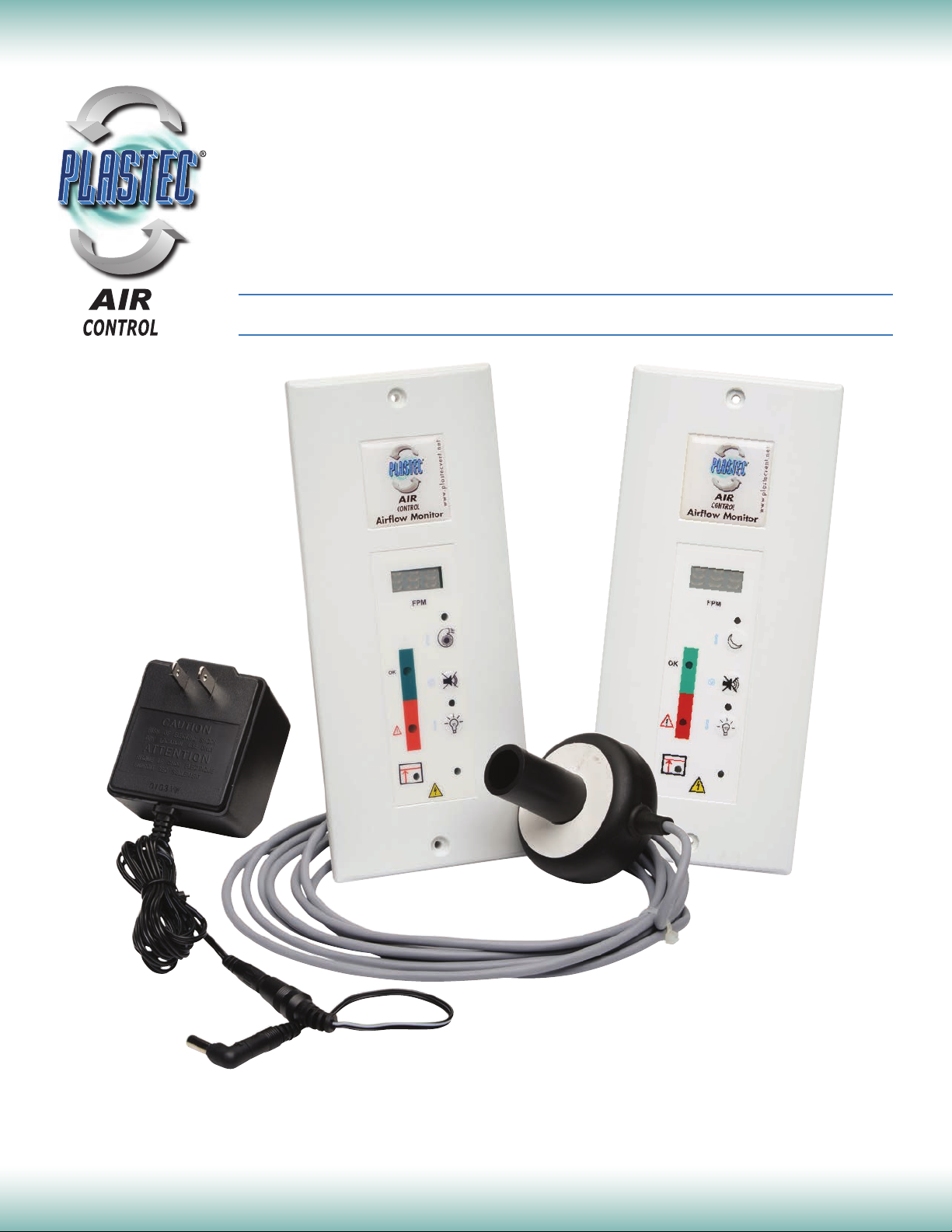
Laboratory Airflow Monitors & Controls
TYPE A STANDARD &
NIGHT SETBACK
LED & DIGITAL
Specifications and Owner’s Manual
PLASTEC® VENTILATION, INC.
2216 60th Drive East • Bradenton, Florida 34203
(941) 751-7596 • Fax (941) 751-7598 • www.plastecvent.net
Page 2
Laboratory Airflow Monitors & Controls
TYPE A STANDARD & NIGHT SETBACK
LED & DIGITAL
General Description
BENEFITS
• Safety: in accordance with EU laboratory
standard EN 14175
• Ease of installation and maintenance
• Fast and accurate sensor reading
• Attractive design: available in choice of LED or
digital display
RANGE
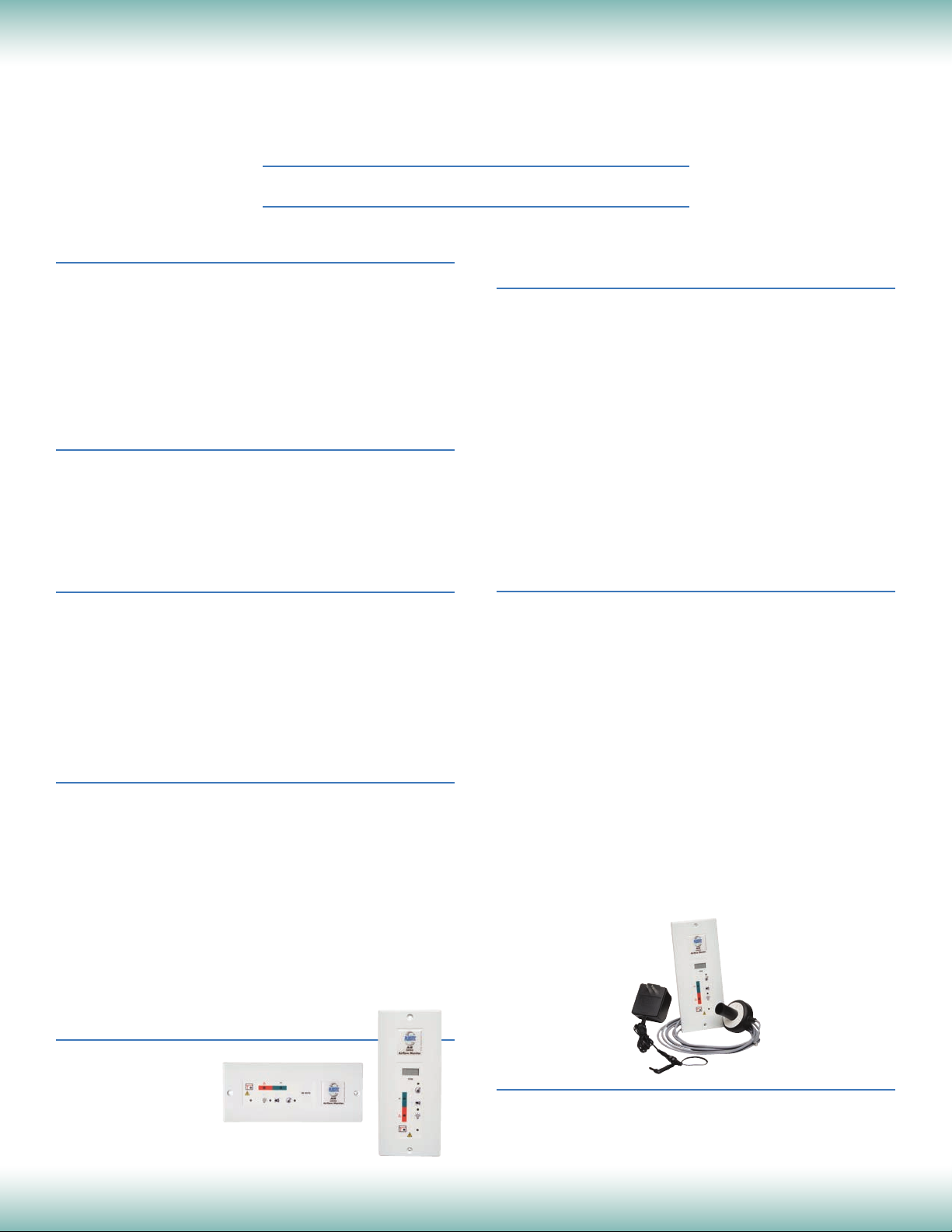
Versions:
• A LED: Monitors airflow, LED lights
• A DIGITAL: Monitors airflow, digital read out in
meter per second or feet per minute
FEATURES
• Audio and visual alarm
• 3 Pushbuttons: Fan On/Off, Light On/Off, Mute
• Alarm disabled when fan switch off
• Sash High
• Auxiliary contacts
• A 15 second or 30 second alarm delay
OPTIONS
• Surface Box Mounting: Plastic enclosure to
mount the face plate and to avoid profile cutting
the service panel.
• Alarm Relay: A remote alarm can be triggered
from a relay on the controller pcb.
• Battery Back Up: Red LED alarm is still
functional up to 12 hours when unit loses power.
• Custom Resin Stickers: Customizable resin
stickers with logo, address, etc.
INTERNATIONAL STANDARDS
COMPLIANCE
In accordance with:
- European laboratory standard EN 14175-2
- Electromagnetic standards EN
61326 : 1997/A1 : 1998/A2 : 2001/A3 : 2003
(Test report RC-05-42060-1) US FCC Part 15
Class B edition 2005 (Test report RC-05 42060-2-A)
- European RoHS directive governing disposal and
recycling of electronics
- French laboratory standard XPX 15203 of Sept.
1996
- CE
COMPONENTS
• Circuit Board: Panel mounted circuit board to
be installed vertically or horizontally onto fume
cupboard with 2x Ø 2.8 mm / 0.11" screws. IP55
protection ensured by “O” ring seal. Face plate
to be supplied with chemical resistant plastic
sticker (horizontal or vertical) with control/push
buttons on fascia. Surface box mounting optional.
• Numerical and Antistatic Sensor: To be installed
inside fume hood. Sensor measures air speed
variations inside fume hood. Supplied with a
3.5 m (5 m optional) shielded cable with pin
connections onto controller circuit board.
• Power Supply: 115 VAC to 12 VDC power
transformer directly into controller circuit board.
Comes with a wall plug and cord. Adaptor may
be required to fit local power socket.
COLORS
Plastic fascia is
available in:
- White (Standard)
PACKING
• Supplied in cardboard box which includes con-
troller circuit board, face plate, sensor and power
transformer. Surface box mounting optional.
2
Page 3
Laboratory Airflow Monitors & Controls
TYPE A STANDARD & NIGHT SETBACK
LED & DIGITAL
Operating Principle
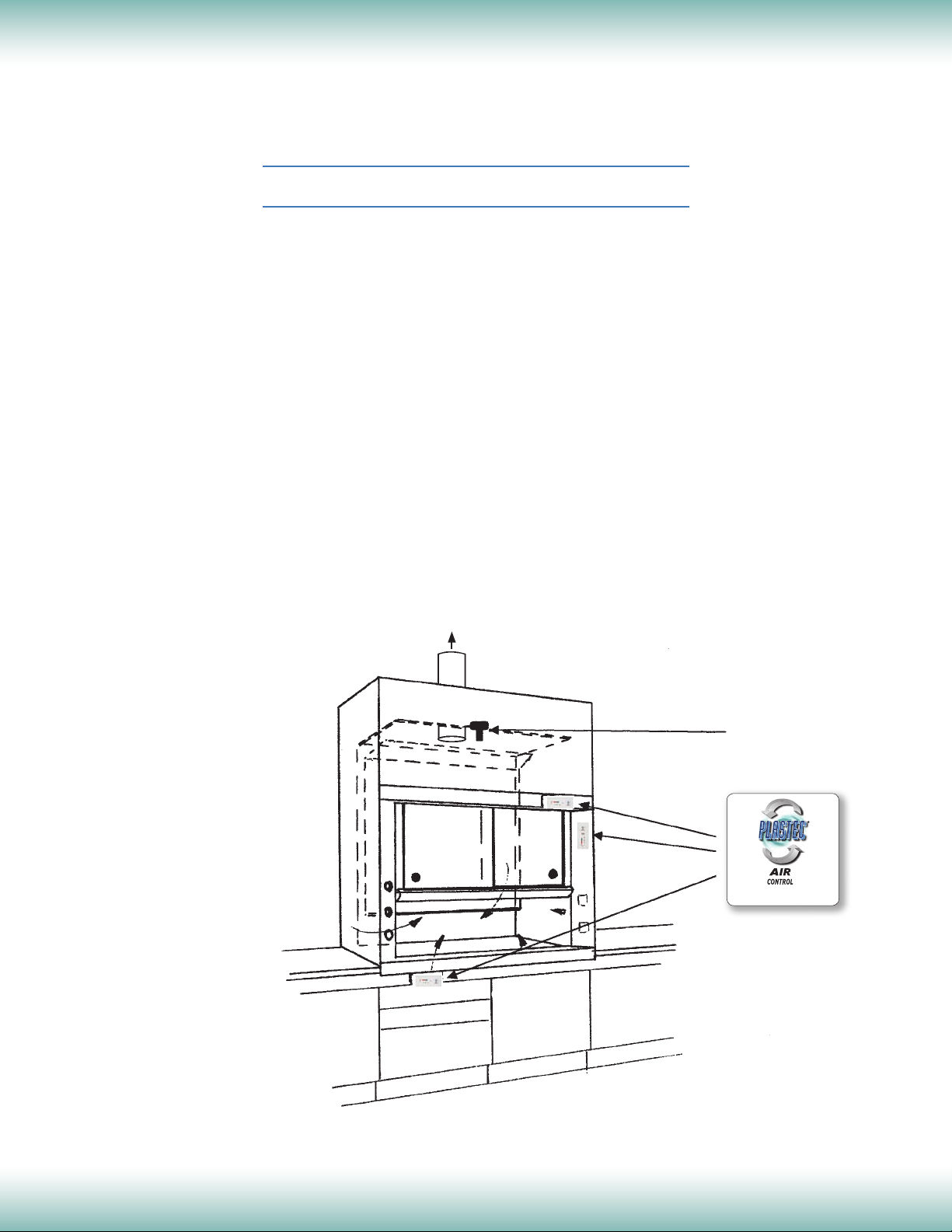
When the fume extraction fan is running, it causes negative pressure inside
the fume cupboard. If the sash is lowered, the negative pressure becomes
more intense causing air to be drawn through the sash opening at an increased
velocity. Conversely, if the sash is raised, the negative pressure becomes less
intense and air velocity reduces.
If an opening is made in the wall of the fume cupboard, air will enter it at a
velocity determined by the same negative pressure that is drawing air into the
sash opening. By sensing the air velocity through an opening, we can determine
its level at the sash opening.
PLASTEC
hole in the cupboard and sending the air velocity measurement obtained to a
display on the fascia panel.
The air velocity level is displayed on the fascia either by LED illumination or
digital read-out. An audible alarm will also sound if the air velocity is too low.
®
AirControl exploits this by the placing of a numerical sensor into a
SENSOR
Airflow Monitor
www.plastecvent.net
2216 60th Drive East • Bradenton, Florida 34203
(941) 751-7596 • Fax (941) 751-7598 • www.plastecvent.net
3
Page 4
Controller
Sensor
Laboratory Airflow Monitors & Controls
TYPE A STANDARD
LED & DIGITAL
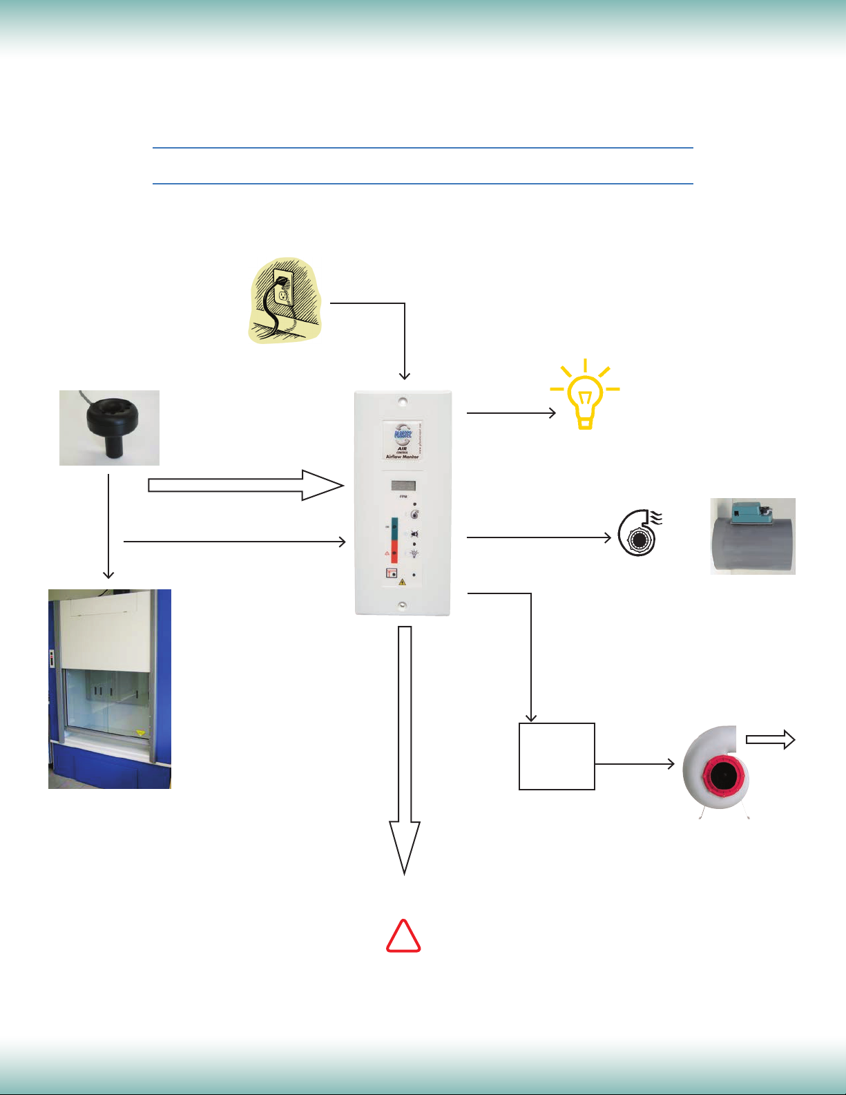
Schematic AirControl A LED & Digital
115 VAC / 12 VDC
Power Supply
Hood Light
on/off relay
Sensor
Signal Input
Motorized
Damper
Sash movement
=
Pressure decrease
or increase
Sash High Alarm Input
OUTPUT:
0 to 10V
or
4-20mA
Air speed
monitoring & control
Air Make-up
on/off relay
Fan on/off
relay
Motor
Starter
Relay
Make-up
Fan
OR
PLASTEC
Extraction Fan
®
!
If air speed is low
2216 60th Drive East • Bradenton, Florida 34203
(941) 751-7596 • Fax (941) 751-7598 • www.plastecvent.net
4
Page 5

Laboratory Airflow Monitors & Controls
TYPE A NIGHT SETBACK
LED & DIGITAL
Schematic AirControl A Night Setback
115 VAC / 12 VDC
Power Supply
Controller
Sensor
Sensor
Signal Input
Hood Light
on/off contact
Sash movement
=
Pressure decrease
or increase
Sash High Alarm Input
Night Setback relay
OUTPUT
Air speed
monitoring & control
!
If airflow is low
2216 60th Drive East • Bradenton, Florida 34203
(941) 751-7596 • Fax (941) 751-7598 • www.plastecvent.net
5
Page 6
Laboratory Airflow Monitors & Controls
TYPE A STANDARD
LED & DIGITAL
Specifications
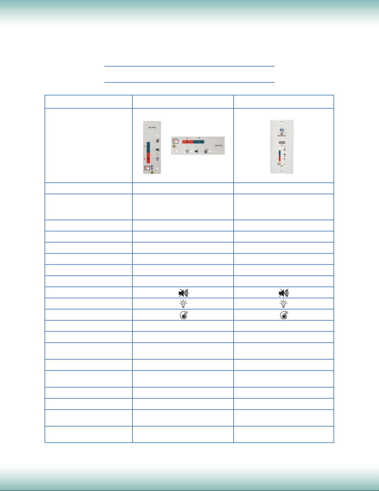
AirControl A LED
Part Number 819700 819701
1 green LED for normal air speed 1 green LED for normal air speed
1 red LED flashing for alarm 1 red LED flashing for alarm
No digital display 3 digit display with velocity reading
Units
Display Range N/A 0 - 2.00 m/s / 0 - 400 FPM
Alarm Setpoint
Alarm Delay Selectable: 15s or 30s Selectable: 15s or 30s
Analog Output NA NA
Alarm Indication
Standard: below 0.39m/s / 78 FPM Standard: below 0.39m/s / 78 FPM
1 red LED flashing & audible buzzer 1 red LED flashing & audible buzzer
N/A meter per second (m/s) / FPM
AirControl A Digital
Alarm Mute
Light On/Off
Fan On/Off
Alarm Relay
Battery Back Up
Sash High Input
sash position switch has been tripped sash position switch has been tripped
Mounting Flush or surface box (option) Flush or surface box (option)
Calibration
Power Requirement 12 VDC (power supply included) 12 VDC (power supply included)
Orientation Vertical/Horizontal Vertical
Front fascia: 210L x 90W x 10D mm Front fascia: 210L x 90W x 10D mm
Monitor Dimensions (metric)
Front fascia: 8.27"L x 3.54"W x 0.39"D Front fascia: 8.27"L x 3.54"W x 0.39"D
Monitor Dimensions (U.S.)
2216 60th Drive East • Bradenton, Florida 34203
(941) 751-7596 • Fax (941) 751-7598 • www.plastecvent.net
Audible and orange flashing LED indicate Audible and orange flashing LED indicate
Factory pre-calibrated @ 0.5m/s / 100 FPM
Surface box: 205L x 85W x 14D mm Surface box: 205L x 85W x 14D mm
Surface box: 8.07"L x 3.35"W x 0.55"D Surface box: 8.07"L x 3.35"W x 0.55"D
Yes, optional Yes, optional
Yes, optional Yes, optional
Factory pre-calibrated @ 0.5m/s / 100 FPM
Recalibration possible Recalibration possible
6
5
Page 7
Laboratory Airflow Monitors & Controls
TYPE A NIGHT SETBACK
LED & DIGITAL
Specifications
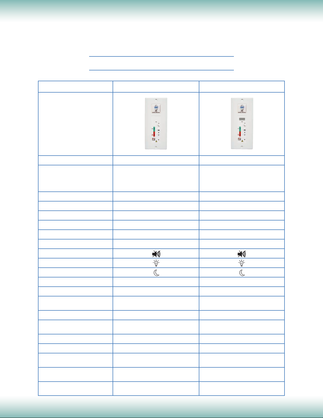
AirControl A LED
Part Number 819700 819701
1 green LED for normal air speed 2 green LED for normal air speed
Display – Visual 1 red LED flashing for alarm "HI" for high air speed displayed
No digital display 1 red LED flashing for alarm
3 digit display with velocity reading
Units
Display Range NA 0 - 400 FPM
Alarm Setpoint
Alarm Delay Selectable: 15s or 30s Selectable: 15s or 30s
Analog Output NA NA
Standard: below 78 FPM Standard: below 78 FPM
NA feet per minute (FPM)
AirControl A DIGITAL
Alarm Indication
Alarm Mute
Light On/Off
Night Setback On/Off
Alarm Relay
Battery Back Up
Sash High Input
sash position switch has been tripped sash position switch has been tripped
Mounting Flush or surface box (option) Flush or surface box (option)
Calibration
Power Requirement 12 VDC (115 VAC power supply) 12 VDC (115 VAC power supply)
Orientation Vertical Vertical
Options
Battery Back Up, Custom Stickers Battery Back Up, Custom Stickers
Front fascia: 210L x 90W x 10D mm Front fascia: 210L x 90W x 10D mm
Monitor Dimensions (metric)
Front fascia: 8.27"L x 3.54"W x 0.39"D Front fascia: 8.27"L x 3.54"W x 0.39"D
Monitor Dimensions (U.S.)
Surface Box, Alarm Relay, Surface Box, Alarm Relay,
Surface box: 8.07"L x 3.35"W x 0.55"D Surface box: 8.07"L x 3.35"W x 0.55"D
1 red LED flashing & audible buzzer 1 red LED flashing & audible buzzer
Yes, optional Yes, optional
Yes, optional Yes, optional
Audible and orange flashing LED indicate Audible and orange flashing LED indicate
Factory pre-calibrated @ 100 FPM
Recalibration possible Recalibration possible
Surface box: 205L x 85W x 14D mm Surface box: 205L x 85W x 14D mm
Factory pre-calibrated @ 100 FPM
7
Page 8
Laboratory Airflow Monitors & Controls
TYPE A STANDARD & NIGHT SETBACK
LED & DIGITAL
Contacts & Features
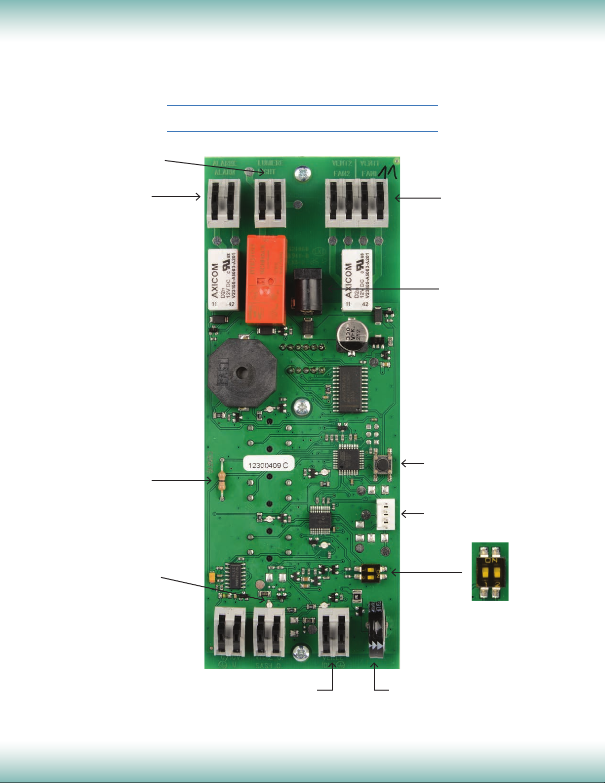
Contact Light On/Off Control
220v 3A
VENT1: Fume fan to
Alarm Relay
220v 3A
(optional)
inverter ‘run’ relay
VENT2: Make-up fan
220v 3A
Power Supply:
115 VAC/12 VDC input
Resistance to be cut
for night setback use
Sash High Contact
Reset
Sensor Connection
Settings:
1. On: Alarm always active
Off: Alarm disabled when fan is off
2. Alarm delay setting:
On: 30 seconds
Off: 15 seconds
Auxiliary contact or
Night setback contact
2216 60th Drive East • Bradenton, Florida 34203
(941) 751-7596 • Fax (941) 751-7598 • www.plastecvent.net
Battery back up
Rechargeable (optional)
ON
OFF
8
5
Page 9
Laboratory Airflow Monitors & Controls
TYPE A STANDARD & NIGHT SETBACK
LED & DIGITAL
Specifications
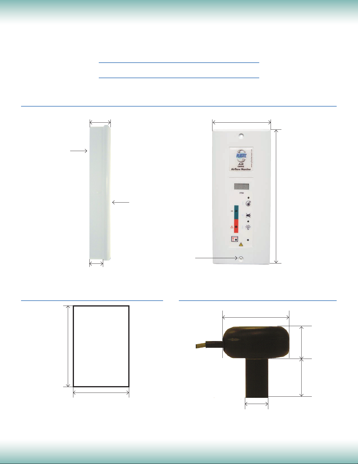
MONITOR & MOUNTING BOX
Mounting Box
35 mm / 1.38"
24 mm / 0.94"
90 mm / 3.54"
210 mm / 8.27"
Face Plate
Ø 2.8 mm / 0.11"
PANEL CUTOUT DIMENSION
17 mm / 0.67"
7.5 mm / 0.30"
NOTE: All dimensions in mm /inches
2216 60th Drive East • Bradenton, Florida 34203
(941) 751-7596 • Fax (941) 751-7598 • www.plastecvent.net
SENSOR
Cable L = 3.5m /
137.76” (11.48')
65 mm / 2.56"
Ø 22 mm / 0.87"
28 mm / 1.10"
40 mm / 1.57"
9
5
Page 10
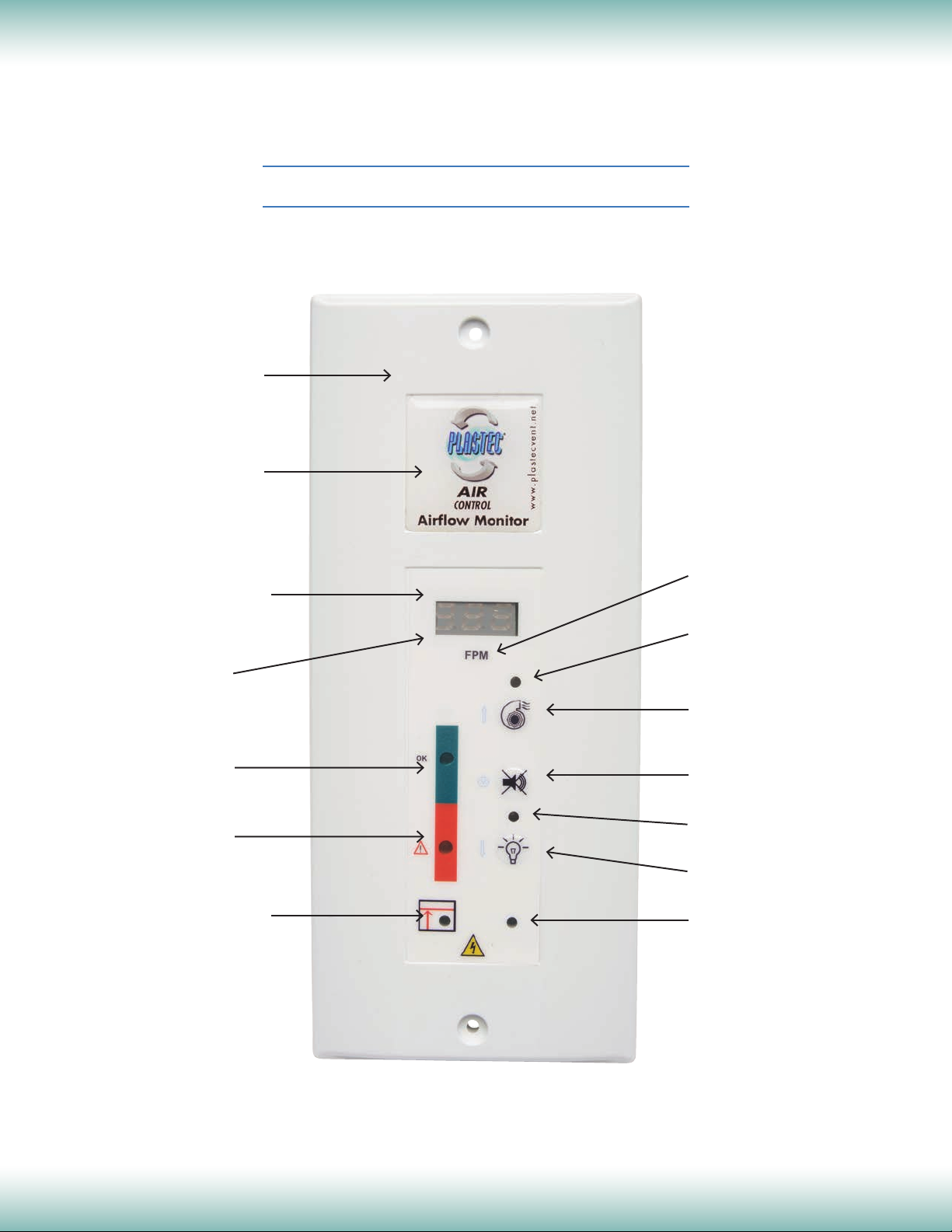
Laboratory Airflow Monitors & Controls
Front plate/fascia
Resin Sticker
TYPE A STANDARD
LED & DIGITAL
Overall View
Chemical and pressure
resistant sticker
Digital display.
Not applicable on
LED version
One green LED lit up:
Airow OK
Flashing red LED for
alarm: air speed too low
Sash high LED. Starts
ashing when sash
position switch has
been tripped
M/S or FPM
LED fan on/off indicator
If fan on, LED orange
Fan on/off push button
Alarm Mute push button
LED light on/off indicator
If light on, LED orange
Light on/off push button
Calibration LED. Should
be off when calibration is
completed
2216 60th Drive East • Bradenton, Florida 34203
(941) 751-7596 • Fax (941) 751-7598 • www.plastecvent.net
10
5
Page 11
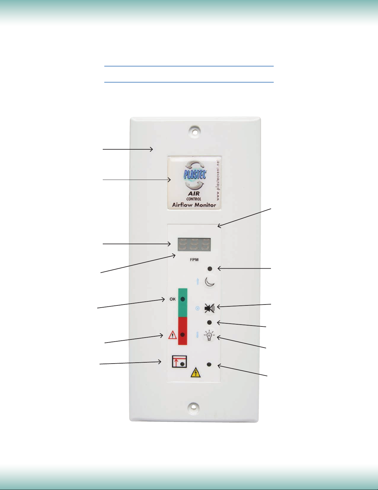
Laboratory Airflow Monitors & Controls
TYPE A NIGHT SETBACK
Front plate/fascia
Customizable
Resin Sticker
LED & DIGITAL
Overall View
Chemical and pressure
resistant sticker
Digital display
in m/s or fpm
“HI” displayed:
Airow too high
One green LED lit up:
Airow OK
Flashing red LED for
alarm: air speed too low
Sash high LED. Starts
ashing when sash
position switch has
been tripped
Night Setback on/off
indicator. If LED lit up,
night setback is on.
Alarm cannot sound
Alarm Mute on/off
push button
LED light on/off indicator
If light on, LED orange
Light on/off push button
Calibration LED. Should
be off when calibration is
completed
2216 60th Drive East • Bradenton, Florida 34203
(941) 751-7596 • Fax (941) 751-7598 • www.plastecvent.net
11
Page 12

Laboratory Airflow Monitors & Controls
TYPE A STANDARD & NIGHT SETBACK
LED & DIGITAL
Installation, Calibration & Alarm Test
INSTALLATION
1) Drill a Ø 23mm / 0.91" hole either in the top or side of the fume cupboard to allow sensor
positioning. Make sure sensor is not in a turbulent zone where the pressure can fluctuate but
where it can monitor stable changes in pressure. Attention should be paid to dead zones near
the top of the fume cupboard.
2) Proceed with wiring as seen on page “Contacts & Features”.
3) Position and secure monitor to service panel of the fume cupboard with the two self-tapping
screws supplied. Do not forget to position “O” ring seal into the moulded groove in the back of
the face plate.
CONTROLLER SET UP PROCEDURE
All monitors unless indicated otherwise are factory pre-calibrated at 0.5 m/s or 100 FPM. If you need a
different sensor calibration and/or displayed speed reading:
1) Make sure that the ventilation is on. Raise the fume cupoard to its test height e.g. 500mm/19.69".
Control with an anemometer that you have the required front air velocity.
2) Push
or
LED is on and the red LED is flashing indicating controller is in manual set up mode. For the
model without digital display (819700), please go directly to step 4.
3) For digital display model (819701). The display shows automatically 0.5 m/s / 100 FPM. If you
want another value, press “Reset” button at the back of the controller to change the required
speed display from 0.3 m/s / 59 FPM to 0.7 m/s / 138 FPM; that will be memorized as the set
point.
4) Wait for 15 seconds or so for air speed to stabilize.
5) To return to “AUTO” mode, push
the green LED is illuminated: new calibration (above or equal at 0.2 m/s) is accepted.
This is automatically done after 7 minutes in manual mode.
The buzzer beeps 10 times in case of incorrect calibration.
for more than 5 seconds, then release and push simultaneously
for Night Setback within the following 5 seconds. Buzzer sounds twice, the green
again until the buzzer beeps 3 times (about 3 seconds) and
for Standard
All updated information is stored in an internal memory which saves and holds
the data even in case of power cut.
2216 60th Drive East • Bradenton, Florida 34203
(941) 751-7596 • Fax (941) 751-7598 • www.plastecvent.net
12
5
Page 13
Laboratory Airflow Monitors & Controls
TYPE A STANDARD & NIGHT SETBACK
LED & DIGITAL
Installation, Calibration & Alarm Test
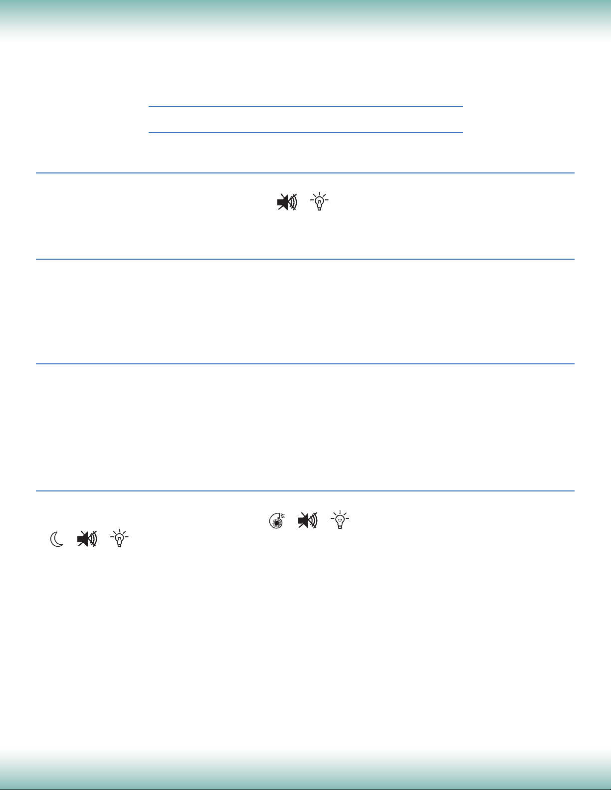
VELOCITY TYPE
To change Digital readout from/to m/s to FPM:
Press simultaneously the following buttons:
until buzzer sounds (about 5 seconds).
DISPLAY MESSAGES
The display will show “HI” for an airflow superior to 1 m/s / 196 FPM and “LO” for an airflow inferior to
0.20 m/s / 40 FPM.
In case of faulty, improper or absent sensor, the display will show “PB”.
FACTORY DATA RESET
Press “Reset” (at the back of the controller) for 15 seconds. Buzzer sounds 5 times.
When using this feature, you restore factory default settings: set point and display at 0.5 m/s / 100
FPM, 7V output to the inverter and all relays and LEDs deactivated.
This operation should be imperatively done in “Auto” mode.
TEST MODE
Test mode is to confirm that all functions are operational. To access test mode, follow this procedure:
1) Press simultaneously following buttons:
* Buzzer sounds twice
2) Press the 3 buttons alternately.
* Buzzer sounds 10 times if malfunction
In case of faulty sensor, the display will show “PB”.
* Buzzer sounds 3 times indicating normal operating mode
for 2 seconds for Night Setback
2216 60th Drive East • Bradenton, Florida 34203
(941) 751-7596 • Fax (941) 751-7598 • www.plastecvent.net
for 2 seconds for Standard or
13
5
Page 14
Laboratory Airflow Monitors & Controls
TYPE A STANDARD & NIGHT SETBACK
LED & DIGITAL
Maintenance, Troubleshooting & Warranty
MAINTENANCE
Front plate and stickers of airflow monitor may be cleaned with mild soap and water on a damp
cloth to remove finger marks, oils and residue. Do not use abrasives. Do not allow liquids to enter
the plastic casing. Dry the monitor thoroughly after cleaning.
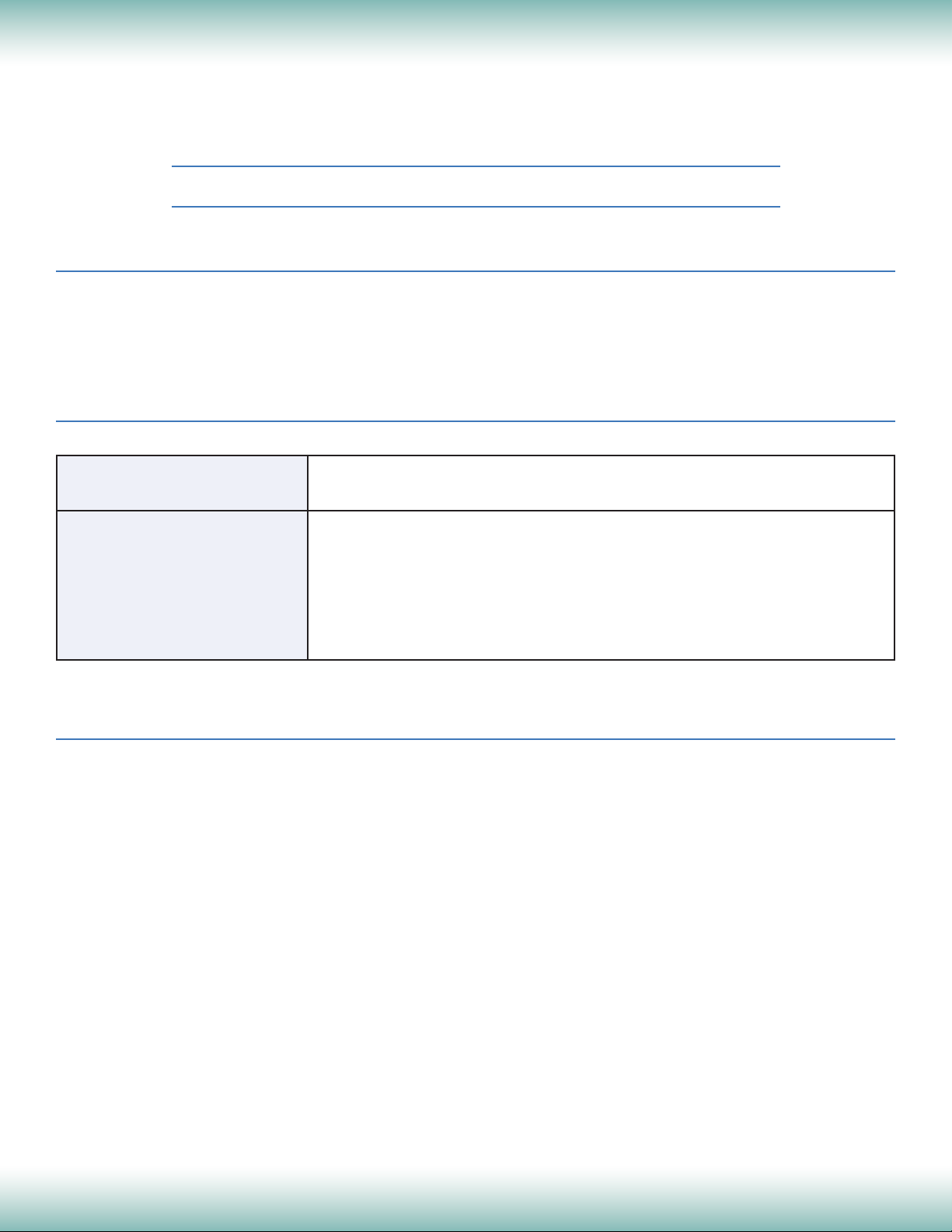
TROUBLESHOOTING
PROBLEM CHECK
No indicators Power supply may not be plugged into AC supply.
Improper alarm setpoint Airflow sensor is factory precalibrated at 0.5 m/s or 100 FPM.
Field reading may be different if sensor is not properly located
or hood design affects stable airflow. If intended air speed is
different than 0.5 m/s / 100 FPM or if actual anemometer reading
is different, follow Controller Set Up Procedure on page 6.
WARRANTY
PLASTEC® Ventilation, Inc. warrants its equipment, products and parts, to be free from defects in
workmanship and material under normal use and service for one year after delivery to the first
user. Product must be returned to point of purchase, with dated bill of sale, within one year of
purchase. If factory return is required, please contact distributor first.
2216 60th Drive East • Bradenton, Florida 34203
(941) 751-7596 • Fax (941) 751-7598 • www.plastecvent.net
14
5
 Loading...