

Page 1
Page 2

INTRODUCTION
DO NOT INSTALL, USE OR OPERATE THIS EQUIPMENT UNTIL
THIS MANUAL HAS BEEN READ AND UNDERSTOOD.
The installer assumes ultimate responsibility for ensuring that
current installation regulations are fully observed and that the
exhaust fan receives adequate protection from adverse electrical,
mechanical, thermal or environmental conditions.
The fan must be regularly inspected and maintained by qualied
staff in order to avoid damage and accidents. Material damage
and personal injuries can result from improper service.
Fan must not be installed near working or common areas. The
fan must always be installed in such a way that rotating parts
cannot be touched.
Products must be stored in a clean dry place protected from
temperature uctuations. If it is necessary to store equipment
outdoors, protect from the elements as much as possible. Keep
equipment dry and clean.
Please, carefully follow the instructions set out below.
Page 3

1. INSTALLATION
WARNING! Before installation begins check for and clear any foreign materials in
the Fan/Blower and other components to be attached to the Fan/Blower.
CAUTION! Before installation check that all locking screws and nuts and bolts are
tightened properly, including the motor screws/nuts.
DANGER! Check the electrical connections and wiring.
Fan should be connected to ductwork with Flexible PVC Reducer/Couplings to avoid
air leaks and to help in vibration isolation and noise reduction.
If Exhaust Stacks are to be mounted to the Fan/Blower, they must be supported to
avoid placing too much weight on the Blower, which could cause damage.
CAUTION! Avoid continuous air stream temperature use higher than 140ºF/60ºC.
Make sure the Fan/Blower Assembly is securely attached to a rm foundation at the
mounting location to prevent vibration and movement.
WARNING! The PLASTEC 50 Model Impeller rotates (spins) only in a Counterclock-
wise Direction (CCW). Never reverse the direction of the housing to Clockwise (CW)
to prevent poor performance and possible damage. The certied performance for
the PLASTEC 50 Model is for the correct orientation/direction of impeller rotation
as outlined.
IMPELLER DIRECTION OF ROTATION
ROTATION AND DISCHARGE FOR CENTRIFUGAL FANS
Notes:
(1) Direction of rotation is determined from the drive side
of fan. Standard position is up-blast CCW 360.
Counter-
Clockwise
Up Blast
CCW 360
Counter-
Clockwise
Top Horizontal
CCW 90
(2) On s
(3) CCW 360 and CCW 90 only for the Plastec 50
ingle inlet fans, drive side is always considered as
the side opposite fan inlet.
Page 4
2. ELECTRICAL CONNECTION
The guidelines and safety instructions of the motor manufacturer must be strictly
adhered to. The motor should be wired to the electrical supply in accordance with
the connection diagram within the terminal box.
Please note the performance data on the motor plate.
It is essential that the motor should be protected from electrical overload.
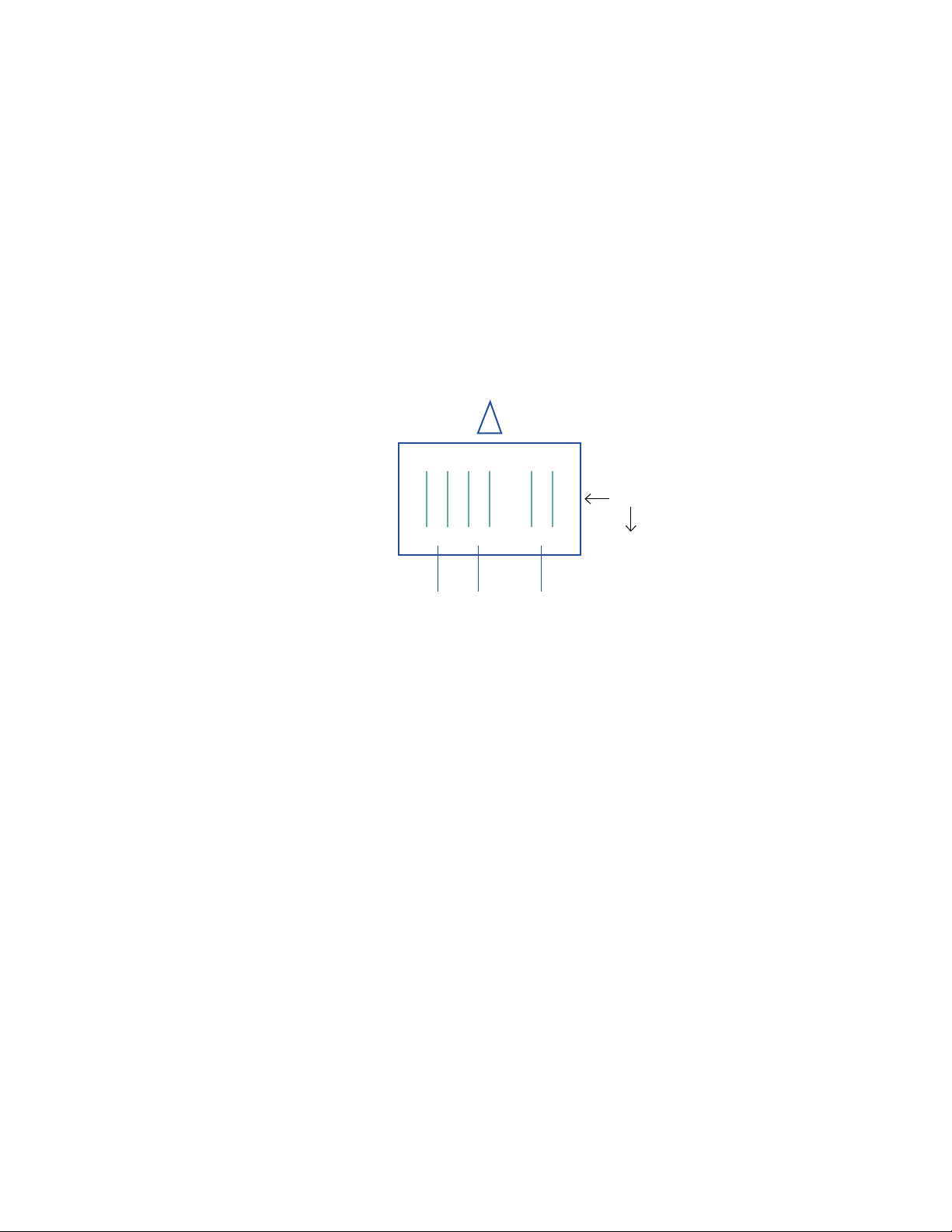
THREE PHASE WIRING
W2 U2 V2
Motor
W1 U1 V1
L1 L2 L3
To Inverter
The electrical installation may only be carried out by an authorized electrician in
accordance with the regulations.
The electrical connection must be permanently secured. Make safe ground connections.
Page 5

3. PRE-START UP
Before beginning any work on the Fan/Blower the electrical supply must be turned
off. The impeller must not be mechanically blocked and should turn freely.
The motor must be equipped with an ON/OFF Switch (Disconnect Switch). The
Switching Device must be in the OFF Position and secured to prevent unintended
operation.
The Electrical Cable must be protected against damage and deterioration and meet
local Electrical Codes.
FREQUENCY INVERTER / VFD
The System Start Up must be controlled by the Frequency Inverter/VFD. The Frequency
Inverter/VFD must be set to prevent unnecessary loads on the Fan/Blower due to
high acceleration or deceleration. In general the startup time for an impeller with
the diameter of 31.50” (800 mm) should be at least 20 seconds.
• Even in case of default of power supply, the operating
maximum temperature should not be exceeded.
• The plastic Fans/Blowers are not adapted for solid
material/particles exhaust.
• The Plastec 50 Fan/Blower should not be used for
potentially explosive atmospheres.
To avoid frequently repeated accelerations and decelerations which could lead to
material fatigue, the process control should be as slow as feasible.
WARNING! After disconnecting the Power Supply of the Frequency Inverter/VFD,
at least 10 seconds must pass before leads or other components of the Frequency
Inverter can be touched. There is a serious risk of injury from stored energy in
the capacitors. Internal components of the Frequency Inverter/VFD should not be
touched until at least 10 minutes pass. Refer to the VFD Manual for more safety
information.
Page 6

4. FUNCTIONING
• The Fan/Blower must be protected against surging.
• Material deposits on the impeller could cause damage;
remov
• In dirty locations the motor must be cleaned regularly.
e before operation of the Fan/Blower.
5. MAINTENANCE
After the rst month of operating, the fan must be maintained as follows:
• Check the running of the fan
• Check the motor temperature
• Remov
impeller and the motor
The fan may only be maintained by trained personnel who are authorized to carry
out such work.
Fans should be carefully checked at least once a year, or more often if conditions
require.
e any dust deposits/material build-up on the
Page 7
 Loading...