

Page 1
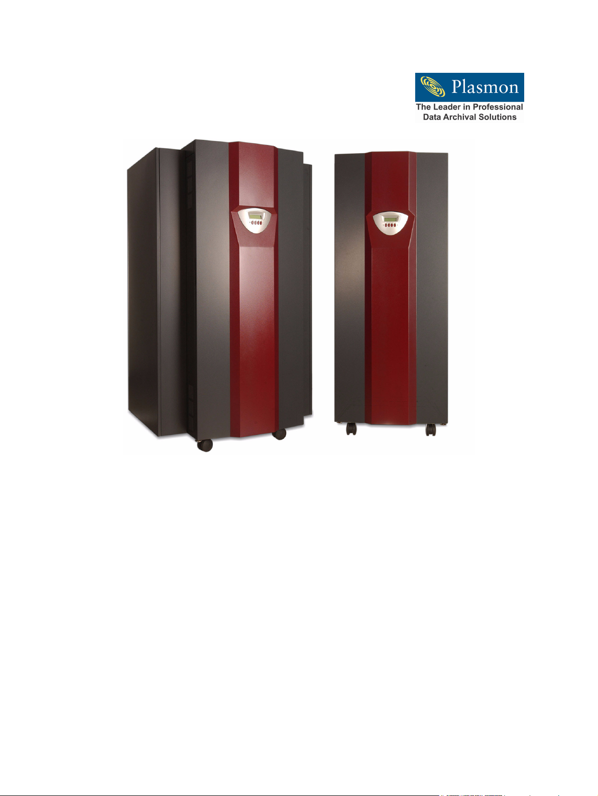
The Plasmon Enterprise
D-Series
D875 - D2175 Libraries ~ DVD Drive
User Manual
P/N 97704577 E
Page 2

Page 3

PREFACE
Copyright
Copyright 2004 by Plasmon®. All rights reserved. This document and the information contained herein
are the property of Plasmon. No part of this document may be reproduced, transmitted, transcribed,
stored in a retrieval system, or translated into any language or computer language in any form or by
any means, electronic, mechanical, magnetic, optical, chemical, manual, or otherwise, without the
express written permission of Plasmon.
United States Office
Plasmon
4425 ArrowsWest Drive
Colorado Springs, CO 80907-3489
European Headquarters, UK
Plasmon Data Limited
Whiting Way
Melbourn, Herts. SG8 6EN
Disclaimer
Plasmon makes no representation or warranties with respect to the contents of this document and
specifically disclaims any implied warranties of merchantability or fitness for any particular purpose.
Further, Plasmon reserves the right to revise this publication without obligation of Plasmon to notify any
person or organization of such revision or changes.
Trademark Notices
Plasmon is a U.S. registered trademark of Plasmon. Rotation Station is a trademark of Plasmon. All
other product names are trademarks or registered trademarks of their respective owners.
Plasmon D875 - D2175 User Manual Preface
Document Revision E Page 1
Page 4

Revision History
Revision Date Description
A September 2002 Initial release.
B November 2002 Updated installation information.
C March 2003 Updated to include Multi Drive.
D June 2003 Minor updates from Service.
E October 2004 Updated format and presentation. Added bay pack-
The most current information about this product is available on the
Plasmon web site (www.plasmon.com, or www.plasmon.co.uk).
ing to Ch 2.
NOTE
Preface Plasmon D875 - D2175 User Manual
Page 2 Document Revision E
Page 5
Conventions Used
A WARNING is used to alert the reader to situations or conditions
that could potentially result in personal injury, fire hazard, or
equipment damage.
A CAUTION is used to warn of undesirable procedures, or of
situations in which equipment damage could result.
WARNING
CAUTION
NOTE
A NOTE is used to emphasize an area of text or to provide
additional information.
Plasmon D875 - D2175 User Manual Preface
Document Revision E Page 3
Page 6
Product Warranty
This Plasmon library is warranted free from defects in materials, parts, and workmanship and to
conform to the current product specification upon delivery. For the specific details of your warranty,
refer to your sales contract or contact the company from which the library was purchased.
The Plasmon quality system is in compliance with and registered to ISO9001:2000. All products are
assembled from new or remanufactured parts.
The warranty for the library shall not apply to failures of any unit when:
• The library is repaired by anyone other than Plasmon personnel or approved agent.
• The library is physically abused or is used in a manner that is inconsistent with the operating
instructions or product specification defined by Plasmon.
• The library is used with incompatable software and or firmware.
• The library fails because of accident, misuse, abuse, neglect, mishandling, misapplication,
alteration, faulty installation, modification, or service by anyone other than the factory service
center or its approved agent.
• The library is repaired by anyone, including an approved agent, in a manner that is contrary to the
maintenance or installation instructions supplied by Plasmon.
• The Plasmon serial number tag is removed.
• The library is damaged because of improper packaging on return.
CAUTION
Returning the library in unauthorized packaging may damage the
unit and void the warranty.
If problems with the library occur, contact your maintenance
organization. Do not void the product warranty by allowing
untrained or unauthorized personnel to attempt repairs.
WARNING
Untrained personnel operating the library may create dangerous
situations. This could lead to physical harm to the operator, data
loss, or disabling of the library system.
Please review and observe all safety rules concerning the
operation of the library.
Preface Plasmon D875 - D2175 User Manual
Page 4 Document Revision E
Page 7

TABLE OF CONTENTS
PREFACE . . . . . . . . . . . . . . . . . . . . . . . . . . . . . . . . . . . . . . . . . . . . . . . . . 1
Copyright . . . . . . . . . . . . . . . . . . . . . . . . . . . . . . . . . . . . . . . . . . . . . . . . . . . . . . . . . . . . . .1
Disclaimer . . . . . . . . . . . . . . . . . . . . . . . . . . . . . . . . . . . . . . . . . . . . . . . . . . . . . . . . . . . . .1
Trademark Notices. . . . . . . . . . . . . . . . . . . . . . . . . . . . . . . . . . . . . . . . . . . . . . . . . . . . . . .1
Revision History . . . . . . . . . . . . . . . . . . . . . . . . . . . . . . . . . . . . . . . . . . . . . . . . . . . . . . . . .2
Conventions Used . . . . . . . . . . . . . . . . . . . . . . . . . . . . . . . . . . . . . . . . . . . . . . . . . . . . . . .3
Product Warranty . . . . . . . . . . . . . . . . . . . . . . . . . . . . . . . . . . . . . . . . . . . . . . . . . . . . . . . .4
LIST OF FIGURES . . . . . . . . . . . . . . . . . . . . . . . . . . . . . . . . . . . . . . . . . . . 7
IST OF TABLES . . . . . . . . . . . . . . . . . . . . . . . . . . . . . . . . . . . . . . . . . . . . 9
L
HAPTER 1
C
RODUCT OVERVIEW . . . . . . . . . . . . . . . . . . . . . . . . . . . . . . . . . . . . . . . 11
P
General Information . . . . . . . . . . . . . . . . . . . . . . . . . . . . . . . . . . . . . . . . . . . . . . . . . . . . . 11
Library Models . . . . . . . . . . . . . . . . . . . . . . . . . . . . . . . . . . . . . . . . . . . . . . . . . . . . . . . . . . . . 11
Command Processing . . . . . . . . . . . . . . . . . . . . . . . . . . . . . . . . . . . . . . . . . . . . . . . . . . . . . . 11
Media Movement . . . . . . . . . . . . . . . . . . . . . . . . . . . . . . . . . . . . . . . . . . . . . . . . . . . . . . . . . . 11
Bulk Loading and Unloading Media . . . . . . . . . . . . . . . . . . . . . . . . . . . . . . . . . . . . . . . . . . . . 11
The Magazine . . . . . . . . . . . . . . . . . . . . . . . . . . . . . . . . . . . . . . . . . . . . . . . . . . . . . . . . .12
Media and Magazine Handling . . . . . . . . . . . . . . . . . . . . . . . . . . . . . . . . . . . . . . . . . . . . . . . . 13
Major Hardware Components . . . . . . . . . . . . . . . . . . . . . . . . . . . . . . . . . . . . . . . . . . . . .14
Front Access Door . . . . . . . . . . . . . . . . . . . . . . . . . . . . . . . . . . . . . . . . . . . . . . . . . . . . . . . . . 14
Front Panel Display . . . . . . . . . . . . . . . . . . . . . . . . . . . . . . . . . . . . . . . . . . . . . . . . . . . . . . . . 14
Magazine Access Door. . . . . . . . . . . . . . . . . . . . . . . . . . . . . . . . . . . . . . . . . . . . . . . . . . . . . . 14
Magazine Slots . . . . . . . . . . . . . . . . . . . . . . . . . . . . . . . . . . . . . . . . . . . . . . . . . . . . . . . . . . . . 14
Import/Export Port (I/E). . . . . . . . . . . . . . . . . . . . . . . . . . . . . . . . . . . . . . . . . . . . . . . . . . . . . . 15
Drive Modules. . . . . . . . . . . . . . . . . . . . . . . . . . . . . . . . . . . . . . . . . . . . . . . . . . . . . . . . . . . . . 15
Main Power Switch and Power Cable . . . . . . . . . . . . . . . . . . . . . . . . . . . . . . . . . . . . . . . . . . 15
SCSI Interface . . . . . . . . . . . . . . . . . . . . . . . . . . . . . . . . . . . . . . . . . . . . . . . . . . . . . . . . . . . . 15
Power Supplies. . . . . . . . . . . . . . . . . . . . . . . . . . . . . . . . . . . . . . . . . . . . . . . . . . . . . . . . . . . . 15
Rear Access Door . . . . . . . . . . . . . . . . . . . . . . . . . . . . . . . . . . . . . . . . . . . . . . . . . . . . . . . . . 16
Lift Assembly . . . . . . . . . . . . . . . . . . . . . . . . . . . . . . . . . . . . . . . . . . . . . . . . . . . . . . . . . . . . . 16
Media Transport Element (MTE) . . . . . . . . . . . . . . . . . . . . . . . . . . . . . . . . . . . . . . . . . . . . . . 16
Rotation Station . . . . . . . . . . . . . . . . . . . . . . . . . . . . . . . . . . . . . . . . . . . . . . . . . . . . . . . . . . . 16
Storage Slot Map . . . . . . . . . . . . . . . . . . . . . . . . . . . . . . . . . . . . . . . . . . . . . . . . . . . . . . . . . . 16
CHAPTER 2
LIBRARY INSTALLATION . . . . . . . . . . . . . . . . . . . . . . . . . . . . . . . . . . . . . 17
Getting Started . . . . . . . . . . . . . . . . . . . . . . . . . . . . . . . . . . . . . . . . . . . . . . . . . . . . . . . . .17
Unpacking the Library. . . . . . . . . . . . . . . . . . . . . . . . . . . . . . . . . . . . . . . . . . . . . . . . . . . . . . . 17
Library Position. . . . . . . . . . . . . . . . . . . . . . . . . . . . . . . . . . . . . . . . . . . . . . . . . . . . . . . . . . . . 17
Library Environment . . . . . . . . . . . . . . . . . . . . . . . . . . . . . . . . . . . . . . . . . . . . . . . . . . . . . . . . 18
Power Cable and Power Switch . . . . . . . . . . . . . . . . . . . . . . . . . . . . . . . . . . . . . . . . . . . . . . . 18
Removing Internal Packing Material . . . . . . . . . . . . . . . . . . . . . . . . . . . . . . . . . . . . . . . . . . . . 18
Plasmon D875 - D2175 User Manual Table of Contents
Document Revision E Page 5
Page 8

Library Initialization. . . . . . . . . . . . . . . . . . . . . . . . . . . . . . . . . . . . . . . . . . . . . . . . . . . . . . . . . 19
SCSI Connection . . . . . . . . . . . . . . . . . . . . . . . . . . . . . . . . . . . . . . . . . . . . . . . . . . . . . . .20
Loading Media . . . . . . . . . . . . . . . . . . . . . . . . . . . . . . . . . . . . . . . . . . . . . . . . . . . . . . . . .21
Identifying Storage Slots. . . . . . . . . . . . . . . . . . . . . . . . . . . . . . . . . . . . . . . . . . . . . . . . . . . . . 23
D1525 - D2175 Bay Installation . . . . . . . . . . . . . . . . . . . . . . . . . . . . . . . . . . . . . . . . . . . .24
Library Packing Instructions. . . . . . . . . . . . . . . . . . . . . . . . . . . . . . . . . . . . . . . . . . . . . . .28
Packing Instructions (D1525 - D2175 Expansion Bays) . . . . . . . . . . . . . . . . . . . . . . . . .32
CHAPTER 3
ENU SYSTEM . . . . . . . . . . . . . . . . . . . . . . . . . . . . . . . . . . . . . . . . . . . . 39
M
Navigating the Menu System . . . . . . . . . . . . . . . . . . . . . . . . . . . . . . . . . . . . . . . . . . . . . .39
Power Up Menu Options . . . . . . . . . . . . . . . . . . . . . . . . . . . . . . . . . . . . . . . . . . . . . . . . .41
Main Menu Overview . . . . . . . . . . . . . . . . . . . . . . . . . . . . . . . . . . . . . . . . . . . . . . . . . . . .42
Library Status Menu Overview . . . . . . . . . . . . . . . . . . . . . . . . . . . . . . . . . . . . . . . . . . . . . . . . 44
Set Up Library Menu Overview. . . . . . . . . . . . . . . . . . . . . . . . . . . . . . . . . . . . . . . . . . . . . . . . 47
APPENDIX A
SPECIFICATIONS . . . . . . . . . . . . . . . . . . . . . . . . . . . . . . . . . . . . . . . . . . . 51
Overall Library Specifications. . . . . . . . . . . . . . . . . . . . . . . . . . . . . . . . . . . . . . . . . . . . . .51
Power Cable Specification . . . . . . . . . . . . . . . . . . . . . . . . . . . . . . . . . . . . . . . . . . . . . . . .53
SCSI Cable Specification. . . . . . . . . . . . . . . . . . . . . . . . . . . . . . . . . . . . . . . . . . . . . . . . .53
SCSI Cables and Connectors. . . . . . . . . . . . . . . . . . . . . . . . . . . . . . . . . . . . . . . . . . . . . . . . . 53
SCSI Cable Length. . . . . . . . . . . . . . . . . . . . . . . . . . . . . . . . . . . . . . . . . . . . . . . . . . . . . . . . . 53
SCSI Termination . . . . . . . . . . . . . . . . . . . . . . . . . . . . . . . . . . . . . . . . . . . . . . . . . . . . . . . . . . 53
APPENDIX B
SCSI BUS INFORMATION . . . . . . . . . . . . . . . . . . . . . . . . . . . . . . . . . . . . 55
SCSI Bus Configurations . . . . . . . . . . . . . . . . . . . . . . . . . . . . . . . . . . . . . . . . . . . . . . . . .55
Single Bus Configuration . . . . . . . . . . . . . . . . . . . . . . . . . . . . . . . . . . . . . . . . . . . . . . . . . . . . 55
Dual Bus Configuration. . . . . . . . . . . . . . . . . . . . . . . . . . . . . . . . . . . . . . . . . . . . . . . . . . . . . . 56
Triple Bus Configuration . . . . . . . . . . . . . . . . . . . . . . . . . . . . . . . . . . . . . . . . . . . . . . . . . . . . . 57
SCSI ID Configuration . . . . . . . . . . . . . . . . . . . . . . . . . . . . . . . . . . . . . . . . . . . . . . . . . . .58
Drive Combinations . . . . . . . . . . . . . . . . . . . . . . . . . . . . . . . . . . . . . . . . . . . . . . . . . . . . .59
APPENDIX C
SAFETY AGENCY STANDARD. . . . . . . . . . . . . . . . . . . . . . . . . . . . . . . . . . 61
FCC Notice . . . . . . . . . . . . . . . . . . . . . . . . . . . . . . . . . . . . . . . . . . . . . . . . . . . . . . . . . . .61
Industry Canadian Notice per ICES-003 . . . . . . . . . . . . . . . . . . . . . . . . . . . . . . . . . . . . .61
Australia / New Zealand. . . . . . . . . . . . . . . . . . . . . . . . . . . . . . . . . . . . . . . . . . . . . . . . . .61
Taiwan (BSMI) Class A Warning Statement. . . . . . . . . . . . . . . . . . . . . . . . . . . . . . . . . . .62
Laser Safety Notice . . . . . . . . . . . . . . . . . . . . . . . . . . . . . . . . . . . . . . . . . . . . . . . . . . . . .62
CDRH Regulations. . . . . . . . . . . . . . . . . . . . . . . . . . . . . . . . . . . . . . . . . . . . . . . . . . . . . .62
Lithium Battery . . . . . . . . . . . . . . . . . . . . . . . . . . . . . . . . . . . . . . . . . . . . . . . . . . . . . . . . .62
APPENDIX D
RROR CODES . . . . . . . . . . . . . . . . . . . . . . . . . . . . . . . . . . . . . . . . . . . . 63
E
NDEX . . . . . . . . . . . . . . . . . . . . . . . . . . . . . . . . . . . . . . . . . . . . . . . . . . . 85
I
ONTACTING PLASMON . . . . . . . . . . . . . . . . . . . . . . . . . . . . . . . . . . . . . 87
C
Table of Contents Plasmon D875 - D2175 User Manual
Page 6 Document Revision E
Page 9

LIST OF FIGURES
The Bulk Loading Magazine . . . . . . . . . . . . . . . . . . . . . . . . . . . . . . . . . . . . . . . . . . . . . . . . . . . . . . . . 12
D875 - D2175 Library, Front View . . . . . . . . . . . . . . . . . . . . . . . . . . . . . . . . . . . . . . . . . . . . . . . . . . . . 14
D875 - D2175 Library, Rear View . . . . . . . . . . . . . . . . . . . . . . . . . . . . . . . . . . . . . . . . . . . . . . . . . . . . 16
Space Planning for the Library . . . . . . . . . . . . . . . . . . . . . . . . . . . . . . . . . . . . . . . . . . . . . . . . . . . . . . 17
D875 - D2175 Power Connector and Power Switch . . . . . . . . . . . . . . . . . . . . . . . . . . . . . . . . . . . . . . 18
Removing the Packing Foam from the MTE . . . . . . . . . . . . . . . . . . . . . . . . . . . . . . . . . . . . . . . . . . . . 19
Connecting the SCSI Interface . . . . . . . . . . . . . . . . . . . . . . . . . . . . . . . . . . . . . . . . . . . . . . . . . . . . . . 20
Magazine Slots . . . . . . . . . . . . . . . . . . . . . . . . . . . . . . . . . . . . . . . . . . . . . . . . . . . . . . . . . . . . . . . . . . 21
Slot Storage Map. . . . . . . . . . . . . . . . . . . . . . . . . . . . . . . . . . . . . . . . . . . . . . . . . . . . . . . . . . . . . . . . . 23
Expansion Bay Installation (a) . . . . . . . . . . . . . . . . . . . . . . . . . . . . . . . . . . . . . . . . . . . . . . . . . . . . . . . 24
Expansion Bay Installation (b) . . . . . . . . . . . . . . . . . . . . . . . . . . . . . . . . . . . . . . . . . . . . . . . . . . . . . . . 25
Expansion Bay Installation (c) . . . . . . . . . . . . . . . . . . . . . . . . . . . . . . . . . . . . . . . . . . . . . . . . . . . . . . . 26
Expansion Bay Installation (d) . . . . . . . . . . . . . . . . . . . . . . . . . . . . . . . . . . . . . . . . . . . . . . . . . . . . . . . 26
Expansion Bay Installation (e) . . . . . . . . . . . . . . . . . . . . . . . . . . . . . . . . . . . . . . . . . . . . . . . . . . . . . . . 27
Expansion Bay Installation (f) . . . . . . . . . . . . . . . . . . . . . . . . . . . . . . . . . . . . . . . . . . . . . . . . . . . . . . . 27
Packing the D875 - D2175 Libraries (a) . . . . . . . . . . . . . . . . . . . . . . . . . . . . . . . . . . . . . . . . . . . . . . . 28
Packing the D875 - D2175 Libraries (b) . . . . . . . . . . . . . . . . . . . . . . . . . . . . . . . . . . . . . . . . . . . . . . . 29
Packing the D875 - D2175 Libraries (c) . . . . . . . . . . . . . . . . . . . . . . . . . . . . . . . . . . . . . . . . . . . . . . . 29
Packing the D875 - D2175 Libraries (d) . . . . . . . . . . . . . . . . . . . . . . . . . . . . . . . . . . . . . . . . . . . . . . . 30
Packing the D875 - D2175 Libraries (e) . . . . . . . . . . . . . . . . . . . . . . . . . . . . . . . . . . . . . . . . . . . . . . . 30
Packing the D875 - D2175 Libraries (f) . . . . . . . . . . . . . . . . . . . . . . . . . . . . . . . . . . . . . . . . . . . . . . . . 31
Expansion Bay Packing (a) . . . . . . . . . . . . . . . . . . . . . . . . . . . . . . . . . . . . . . . . . . . . . . . . . . . . . . . . . 32
Expansion Bay Packing (b) . . . . . . . . . . . . . . . . . . . . . . . . . . . . . . . . . . . . . . . . . . . . . . . . . . . . . . . . . 33
Expansion Bay Packing (c) . . . . . . . . . . . . . . . . . . . . . . . . . . . . . . . . . . . . . . . . . . . . . . . . . . . . . . . . . 33
Expansion Bay Packing (d) . . . . . . . . . . . . . . . . . . . . . . . . . . . . . . . . . . . . . . . . . . . . . . . . . . . . . . . . . 34
Expansion Bay Packing (e) . . . . . . . . . . . . . . . . . . . . . . . . . . . . . . . . . . . . . . . . . . . . . . . . . . . . . . . . . 34
Expansion Bay Packing (f) . . . . . . . . . . . . . . . . . . . . . . . . . . . . . . . . . . . . . . . . . . . . . . . . . . . . . . . . . 35
Expansion Bay Packing (g) . . . . . . . . . . . . . . . . . . . . . . . . . . . . . . . . . . . . . . . . . . . . . . . . . . . . . . . . . 35
Expansion Bay Packing (h) . . . . . . . . . . . . . . . . . . . . . . . . . . . . . . . . . . . . . . . . . . . . . . . . . . . . . . . . . 36
Expansion Bay Packing (i). . . . . . . . . . . . . . . . . . . . . . . . . . . . . . . . . . . . . . . . . . . . . . . . . . . . . . . . . . 36
Expansion Bay Packing (j). . . . . . . . . . . . . . . . . . . . . . . . . . . . . . . . . . . . . . . . . . . . . . . . . . . . . . . . . . 37
LCD Display Format . . . . . . . . . . . . . . . . . . . . . . . . . . . . . . . . . . . . . . . . . . . . . . . . . . . . . . . . . . . . . . 39
Power Up LCD Display . . . . . . . . . . . . . . . . . . . . . . . . . . . . . . . . . . . . . . . . . . . . . . . . . . . . . . . . . . . . 41
Main Menu Overview. . . . . . . . . . . . . . . . . . . . . . . . . . . . . . . . . . . . . . . . . . . . . . . . . . . . . . . . . . . . . . 42
Library Status Menu Options . . . . . . . . . . . . . . . . . . . . . . . . . . . . . . . . . . . . . . . . . . . . . . . . . . . . . . . . 44
Set Up Library Menu Options . . . . . . . . . . . . . . . . . . . . . . . . . . . . . . . . . . . . . . . . . . . . . . . . . . . . . . . 47
Single Bus Configuration . . . . . . . . . . . . . . . . . . . . . . . . . . . . . . . . . . . . . . . . . . . . . . . . . . . . . . . . . . . 55
Dual Bus Configuration . . . . . . . . . . . . . . . . . . . . . . . . . . . . . . . . . . . . . . . . . . . . . . . . . . . . . . . . . . . . 56
Triple Bus Configuration . . . . . . . . . . . . . . . . . . . . . . . . . . . . . . . . . . . . . . . . . . . . . . . . . . . . . . . . . . . 57
Plasmon D875 - D2175 User Manual List of Figures
Document Revision E Page 7
Page 10

List of Figures Plasmon D875 - D2175 User Manual
Page 8 Document Revision E
Page 11

LIST OF TABLES
D875 - D2175 Library Models . . . . . . . . . . . . . . . . . . . . . . . . . . . . . . . . . . . . . . . . . . . . . . . . . . . . . . . 11
Plasmon Pre-loaded Media . . . . . . . . . . . . . . . . . . . . . . . . . . . . . . . . . . . . . . . . . . . . . . . . . . . . . . . . . 12
Magazine Slot LED Indicators . . . . . . . . . . . . . . . . . . . . . . . . . . . . . . . . . . . . . . . . . . . . . . . . . . . . . . . 22
Organization of Media in the Library . . . . . . . . . . . . . . . . . . . . . . . . . . . . . . . . . . . . . . . . . . . . . . . . . . 23
LCD Symbols. . . . . . . . . . . . . . . . . . . . . . . . . . . . . . . . . . . . . . . . . . . . . . . . . . . . . . . . . . . . . . . . . . . . 40
Power Up LCD Symbols . . . . . . . . . . . . . . . . . . . . . . . . . . . . . . . . . . . . . . . . . . . . . . . . . . . . . . . . . . . 41
Main Menu Selections . . . . . . . . . . . . . . . . . . . . . . . . . . . . . . . . . . . . . . . . . . . . . . . . . . . . . . . . . . . . . 43
Library Status Menu Selections. . . . . . . . . . . . . . . . . . . . . . . . . . . . . . . . . . . . . . . . . . . . . . . . . . . . . . 45
Set Up Library Menu Selections . . . . . . . . . . . . . . . . . . . . . . . . . . . . . . . . . . . . . . . . . . . . . . . . . . . . . 48
D875 - D2175 Specifications . . . . . . . . . . . . . . . . . . . . . . . . . . . . . . . . . . . . . . . . . . . . . . . . . . . . . . . . 51
Media Specifications . . . . . . . . . . . . . . . . . . . . . . . . . . . . . . . . . . . . . . . . . . . . . . . . . . . . . . . . . . . . . . 52
Maximum Allowable SCSI Cable Length (LVD) . . . . . . . . . . . . . . . . . . . . . . . . . . . . . . . . . . . . . . . . . 53
Factory Default SCSI IDs for the D875 - D2175 Libraries . . . . . . . . . . . . . . . . . . . . . . . . . . . . . . . . . . 58
SCSI Bus and Drive Combinations . . . . . . . . . . . . . . . . . . . . . . . . . . . . . . . . . . . . . . . . . . . . . . . . . . . 59
D875 - D2175 Error Codes . . . . . . . . . . . . . . . . . . . . . . . . . . . . . . . . . . . . . . . . . . . . . . . . . . . . . . . . . 64
Plasmon D875 - D2175 User Manual List of Tables
Document Revision E Page 9
Page 12

List of Tables Plasmon D875 - D2175 User Manual
Page 10 Document Revision E
Page 13
CHAPTER 1
PRODUCT OVERVIEW
General Information
The D875 - D2175 libraries make multiple CD-R, CD-RW, DVD-R, DVD-RAM, and DVD-RW media
available to computer systems for reading and writing using Multi Drive technology. These libraries are
scalable with capacities ranging from 750 to 2175 media. A media transport element (MTE) with a dual
picker makes rapid media exchanges and provides high performance in a multi-user environment. A
patented Rotation Station
Library Models
This manual covers the following Plasmon libraries:
™ allows use of both single and double sided media.
Table 1. D875 - D2175 Library Models
Model Number of Media Slots Number of Drives
D875 750 to 875 2 to 12
D1525 1400 to 1525 2 to 12
D2175 2050 to 2175 2 to 12
The number of media slots varies because adding a drive module, which holds two drives, subtracts 25
media storage slots.
Command Processing
The library responds to SCSI commands from a host computer system to load and unload drives, and
move media within the library.
Media Movement
The media transport element (MTE) is used to move media between the media storage area and the
drives or the I/E port. To speed the process, the MTE can hold two pieces of media simultaneously.
Bulk Loading and Unloading Media
Bulk loading and unloading of media is performed by using the ten slot magazines, and the Bulk Load
Library and Bulk Unload Library front panel menu options.
Plasmon D875 - D2175 User Manual Product Overview
Document Revision E Page 11
Page 14
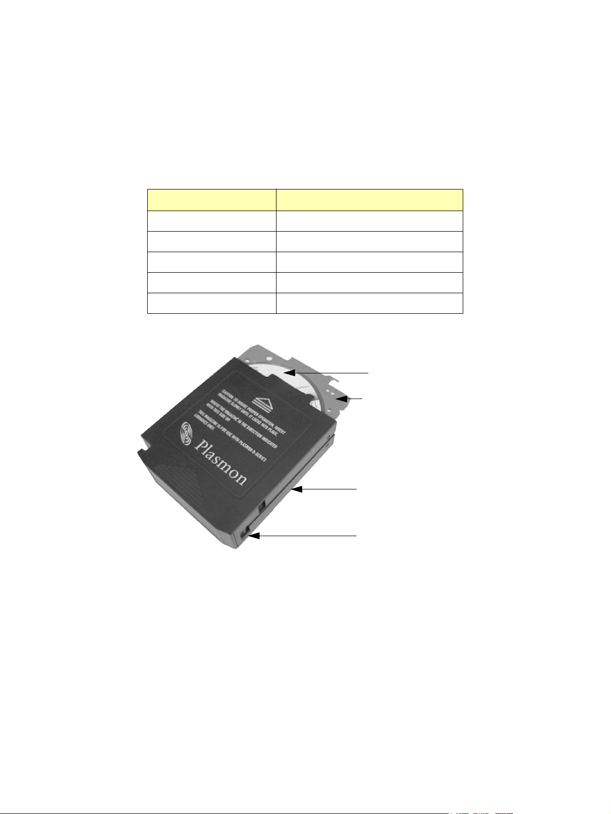
The Magazine
The Plasmon D875 - D2175 library uses CD-R, CD-RW, DVD-R, DVD-RAM, and DVD-RW pre-loaded
media in a ten slot magazine. Packs of 40 pieces of media are also available. Contact Plasmon for
ordering information. In the US, Asia/Pacific, South America, and Canada call 1-800-451-6845. In
Europe, Middle East, and Africa call +44 (0) 1763 262 963.
Table 2. Plasmon Pre-loaded Media
Media Type Capacity
DVD-R 9.4 GB (dual sides)
DVD-R 4.7 GB (single sided)
DVD-RAM 9.4 GB (dual sided)
DVD-RAM 4.7 GB (single sided)
DVD-RAM 2.6 GB (single sided)
Media
Media
Tray
Magazine
Media Tray Release
Figure 1. The Bulk Loading Magazine
Product Overview Plasmon D875 - D2175 User Manual
Page 12 Document Revision E
Page 15

Media and Magazine Handling
To maintain maximum system reliability, the operator should take the time to inspect and clean each
magazine before loading into the library.
CAUTION
Always condition the media to the normal operating temperature
of the room before using them.
Improper handling or an inappropriate environment can damage the media, the magazine, or media
trays. To ensure continued reliability, observe the following:
• When loading a magazine into the library or when handling a magazine, ensure that the case is
clean. Dirty magazines can cause problems in loading or the loss of written data.
• Do not load damaged media trays into a magazine or the library. Damaged media trays can
interfere with system robotics.
• Do not expose the media to moisture or direct sunlight.
NOTE
Plasmon can not guarantee error free library operation if media is
not purchased from Plasmon.
Plasmon supplied media are packaged in a clean room and
quality inspected to ensure error free library operation.
Plasmon D875 - D2175 User Manual Product Overview
Document Revision E Page 13
Page 16
Major Hardware Components
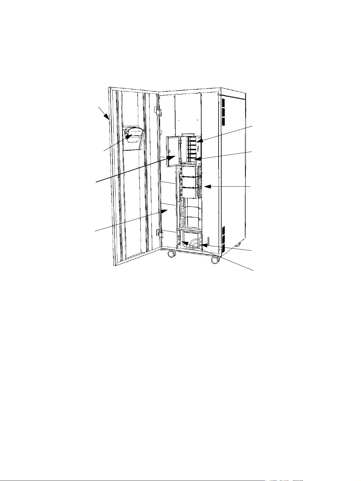
The following figures show the locations of major library hardware components. A brief description of
these components appears after each figure.
Front Access Door
Magazine Slots for
Bulk Loading
(top five slots)
Front Panel Display
Magazine Access Door
Power Supplies
(three supplies
maximum, located
behind the panel)
Figure 2. D875 - D2175 Library, Front View
I/E Port
Drive Modules (6X)
(two drives per
module)
SCSI Bus
Connectors
Main Power Switch
and AC Connector
Front Access Door
The front door provides access to the magazine slots and import/export port (I/E port), drive modules,
power supplies, main power switch, SCSI connections, and circuit boards.
Front Panel Display
The keypad and display which provide the user interface to the system. It is used to display tests,
modes, error codes, and other user related messages.
Magazine Access Door
The magazine access door opens on the magazine slots.
Magazine Slots
There are five magazine slots behind the magazine access door. Each magazine slot holds one
magazine containing up to ten pieces of media. These slots are used to bulk load the library. They can
also be used as removable storage.
Product Overview Plasmon D875 - D2175 User Manual
Page 14 Document Revision E
Page 17

Import/Export Port (I/E)
The Import/Export port (I/E port) holds one magazine containing ten pieces of media. The port is
located below the five magazine slots and is used to remove and load media while the library is on-line.
Drive Modules
Each drive module contains two 120 mm Multi Drives which accommodate CD-R, CD-RW, DVD-R,
DVD-RAM, or DVD-RW media. The drives allow reading and writing of data to the media. Contact
Plasmon for the latest drive updates.
Main Power Switch and Power Cable
The power cable is routed through the bottom of the library to the power connector. The power switch
is located just above the power connector.
SCSI Interface
The connection between the library and a host computer. The interface to the library is LVD SCSI
using a 68-pin high density connection. The host computer must also be set up for LVD SCSI.
Power Supplies
A maximum of three power supplies may be installed in the library. One power supply can power up to
six drives. Two power supplies are required for 12 drives. Three power supplies provide a redundant
power supply option for the library. The supplies are hot swappable.
Plasmon D875 - D2175 User Manual Product Overview
Document Revision E Page 15
Page 18
Rear Access Door
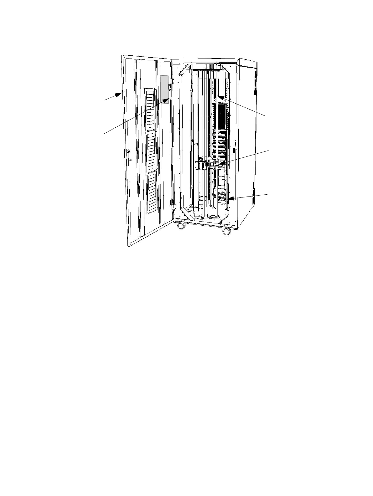
Storage Slot Map
Lift Assembly
Media Transport Element (MTE)
Rotation Station
Figure 3. D875 - D2175 Library, Rear View
Rear Access Door
The rear door provides access to the robotic elements and media slots in the library.
Lift Assembly
The lift assembly provides the vertical and pivotal motion for the media transport element (MTE),
providing access to all media locations.
Media Transport Element (MTE)
The MTE is the mechanism that picks media and moves it between storage locations and the drives.
Rotation Station
The Rotation Station allows use of double-sided media.
Storage Slot Map
The storage slot map is located on the inside of the rear access door. It identifies the media locations
for all D875 - D2175 models.
Product Overview Plasmon D875 - D2175 User Manual
Page 16 Document Revision E
Page 19
CHAPTER 2
LIBRARY INSTALLATION
Getting Started
This chapter provides information for installing the Plasmon D875 - D2175 libraries and the procedures
necessary to quickly put a library on-line.
Unpacking the Library
Save all packing material in case it is ever necessary to ship the library.
Library Position
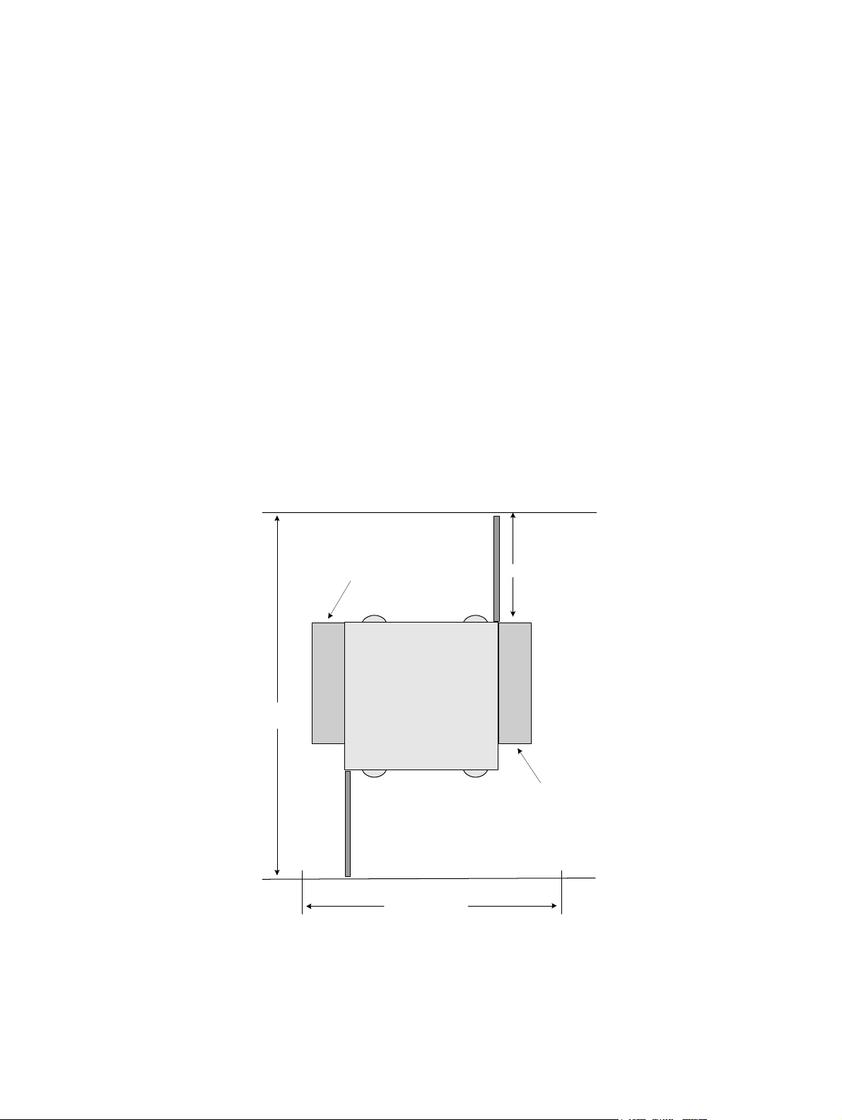
Position the library in a location that allows both the front and rear door to open completely without any
obstructions. The figure below should be used as a guide for library space planning.
Top View
Rear Access Door
Expansion Bay
Library
92" (233.7cm)
Front Access Door
56 " (142.3cm)
Figure 4. Space Planning for the Library
Allow 3 inches (7.6 cm) behind and 2 inches (5.1 cm) on both sides of the unit for sufficient airflow.
35" (89 cm) min
Expansion Bay
Plasmon D875 - D2175 User Manual Library Installation
Document Revision E Page 17
Page 20
Library Environment
To ensure long term reliability, operate the library only between 10° to 32°C (50° to 90°F) and 10% to
90% relative humidity. The media and drives require a clean environment. Excessive dust and dirt can
lead to data loss, and increase service calls.
Power Cable and Power Switch
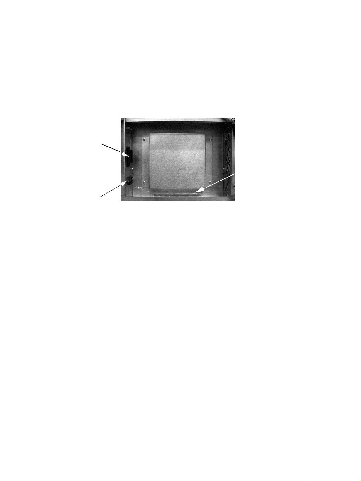
Open the front door of the library and route the supplied power cable through the access hole in the
bottom of the library to the power cable connector.
Power Switch
Thread the power cable
through the bottom of
the library
Power Connector
Figure 5. D875 - D2175 Power Connector and Power Switch
Connect the power cable to a suitable AC source. The power switch is located beside the power cable
connection. Power on the library.
The front panel display now prompts to remove the protective packaging material.
Removing Internal Packing Material
1. Apply power to the library.
2. Follow the instructions on the front panel display to check the time and date and remove
all packing material.
3. Use the supplied key to unlock and open the rear access door. The library is not operable
with this door open.
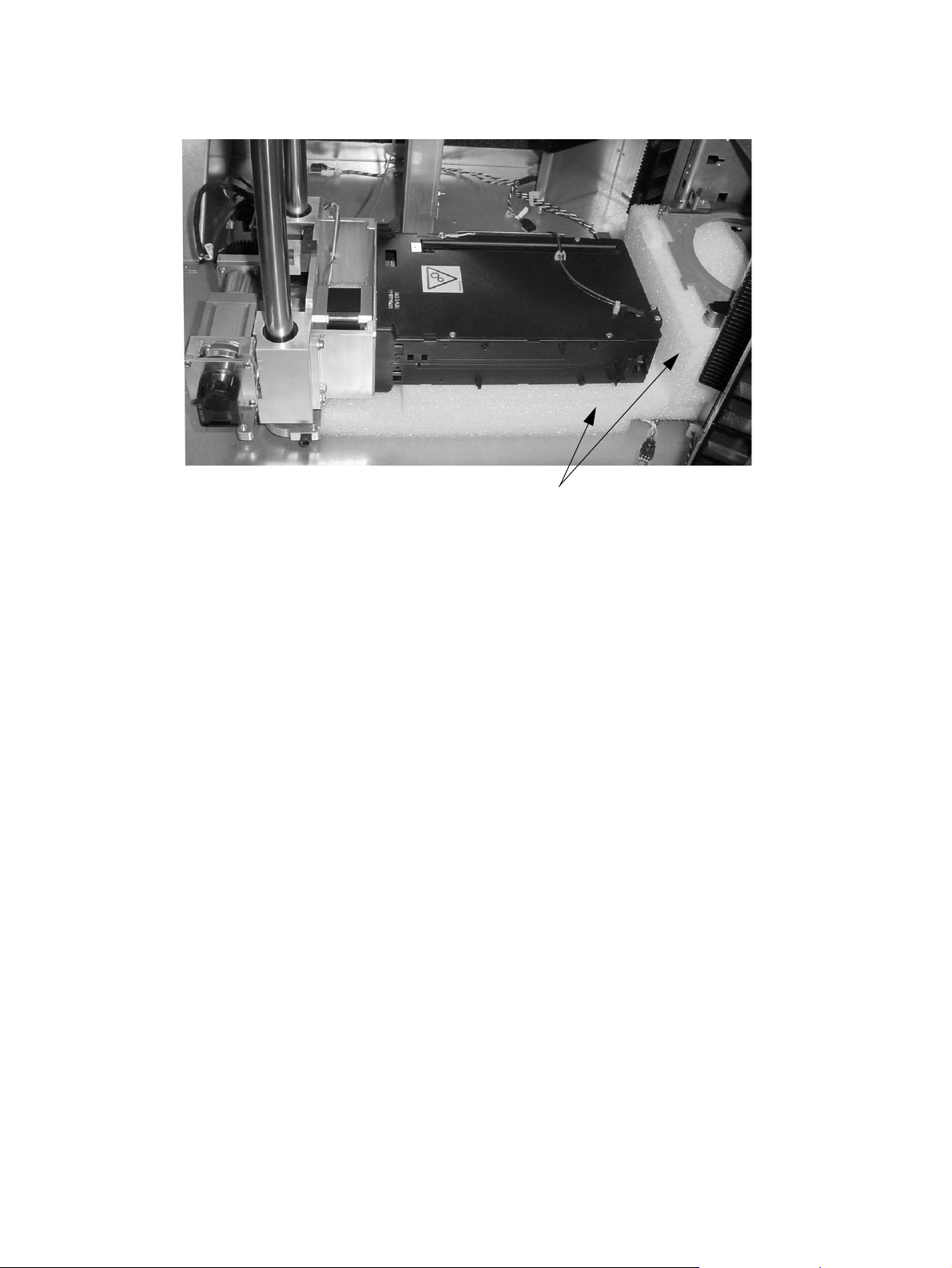
4. Remove the two pieces of MTE protective packing foam. See the figure below.
Library Installation Plasmon D875 - D2175 User Manual
Page 18 Document Revision E
Page 21
Packing Foam
Figure 6. Removing the Packing Foam from the MTE
Library Initialization
After the protective packaging material is removed the user is prompted on the front panel display to
close the rear door. The library now performs a self-calibration and initialization routine.
NOTE
It may be necessary to reboot the host computer for it to recognize
the library.
Some modifications to the host hardware or operating system may be necessary for it to recognize the
library. These modifications may include patches, driver updates, or modifications to the configuration
files. Please consult the host hardware or operating system documentation to see if any of these
applications apply.
Plasmon D875 - D2175 User Manual Library Installation
Document Revision E Page 19
Page 22
SCSI Connection
Turn the library’s power switch to the off position prior to connecting the SCSI interface.
The library requires a host computer with a dedicated LVD SCSI host bus adapter (HBA). Ensure that
the library is powered off prior to connecting the SCSI cables.
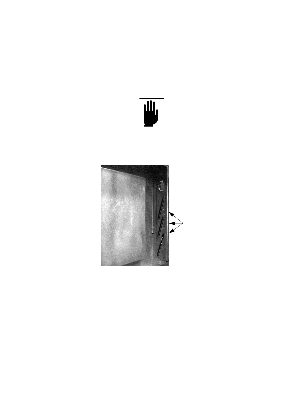
The SCSI cable passes through the bottom of the library into the appropriate SCSI connector inside
the front door of the library.
CAUTION
Ensure the host computer provides an LVD SCSI interface. HVD
SCSI is not compatible with LVD SCSI. If an improper connection
is made, damage to the library or connected equipment could
result.
SCSI Connection
(one, two, or three buses)
Figure 7. Connecting the SCSI Interface
Library Installation Plasmon D875 - D2175 User Manual
Page 20 Document Revision E
Page 23
Loading Media
There are two methods for loading media into the D875 - D2175 libraries:
• High Speed Bulk Loading (recommended): This method is intended as the first time solution to
mass load the library with media when the library is off-line. This method utilizes all six magazine
slots to load the library.
• I/E Port Magazine Loading: This is intended for importing and exporting up to ten pieces of media
in a removable magazine while the library is on-line.
When loading the library for the first time, use the high speed bulk loading method described below:
1. Turn on the power.
2. From the front panel menu select Set Up Library>Offline Operations>Bulk Load Library.
3. Open the library front door and the magazine access door. Note that when the Bulk Load
Library option is selected, the magazine door opens.
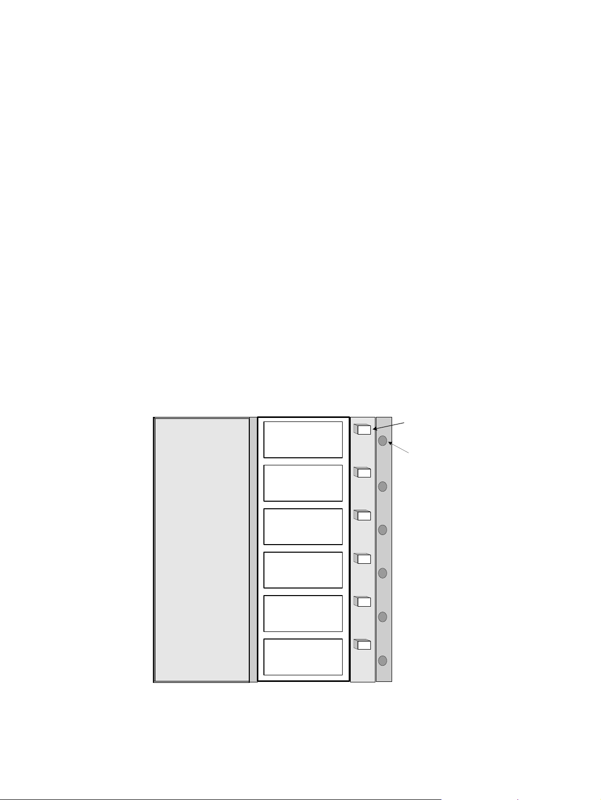
4. Place a pre-loaded magazine in each magazine slot (magazine 1 through magazine 6).
5. When the green LED goes out, remove the appropriate empty magazine and install the
next full magazine.
NOTE
Third party software is required to operate the library
Magazine 6
41 - 50
Magazine 5
31 - 40
Magazine Access Door
Magazine 4
21 - 30
Magazine 3
11 - 20
Magazine 2
1 - 10
I/E Slot
IE 1 - IE 10
Magazine Eject
Button
Load Status
Indicator
Figure 8. Magazine Slots
Plasmon D875 - D2175 User Manual Library Installation
Document Revision E Page 21
Page 24
Table 3. Magazine Slot LED Indicators
LED State Description
On Magazine present or not present
Off N/A
Blinking Magazine may be removed
Bulk Loading Indicators
On Magazine in use
Off Remove to reload with media
Blinking Insert magazine in appropriate position
Library Installation Plasmon D875 - D2175 User Manual
Page 22 Document Revision E
Page 25
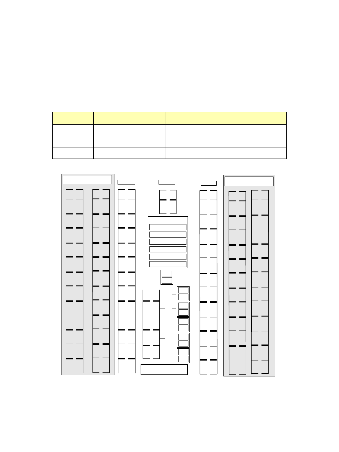
Identifying Storage Slots
Viewing the system through the open rear access door, the columns are numbered from left to right.
The left most column (when the left expansion bay is installed) is column one and the right most
column (when the right expansion bay is installed) is column seven. The media slots are numbered
from top to bottom, except for the magazine slots. The table below shows the model number, the
number of slots, and provides a listing of the columns involved. The column numbers in the table are
listed in sequence.
Table 4. Organization of Media in the Library
Model Number of Slots Column Numbers
D875 750 to 875 All Magazine Slots + 3, 4, and 5
D1525 1400 to 1525 All Magazine Slots + 3, 4, 5, 1, and 2
D2175 2050 to 2175 All Magazine Slots + 3, 4, 5, 1, 2, 6, and 7
(Optional Expansion)
Column 1 Column 2
876
900
901
925
926
950
951
975
976
1000
1001
1025
1026
1050
1051
1075
1076
1100
1101
1125
1126
1150
1151
1175
1176
1200
1201
1225
1226
1250
1251
1275
1276
1300
1301
1325
1326
1350
1351
1375
1376
1400
1401
1425
1426
1450
1451
1475
1476
1500
1501
1525
Column 3
51
75
76
100
101
125
126
150
151
175
176
200
201
225
226
250
251
275
276
300
301
325
326
350
351
375
Column 4
376
400
401
425
Magazine Slots
41 - 50
31 - 40
21 - 30
11 - 20
1 - 10
I/E 1 - I/E 10
Drive
1
Drive
426
450
451
475
476
500
501
525
526
550
2
Or *
Or
Or
Or
Or
Rotation Station
Drive
Drive
Drive
Drive
Drive
Drive
Drive
Drive
10
Drive
11
Drive
12
Column 5
551
575
576
600
601
625
626
650
651
675
676
700
701
725
3
4
5
6
7
8
9
726
750
751
775
776
800
801
825
826
850
851
875
(Optional Expansion)
Column 6 Column 7
1526
1550
1551
1575
1576
1600
1601
1625
1626
1650
1651
1675
1676
1700
1701
1725
1726
1750
1751
1775
1776
1800
1801
1825
1826
1850
1851
1875
1876
1900
1901
1925
1926
1950
1951
1975
1976
2000
2001
2025
2026
2050
2051
2075
2076
2100
2101
2125
2126
2150
2151
2175
Shaded areas represent the optional expansion modules (650 slots each module)
* = Each drive module takes an equivalent space of 25 storage slots
Figure 9. Slot Storage Map
Plasmon D875 - D2175 User Manual Library Installation
Document Revision E Page 23
Page 26
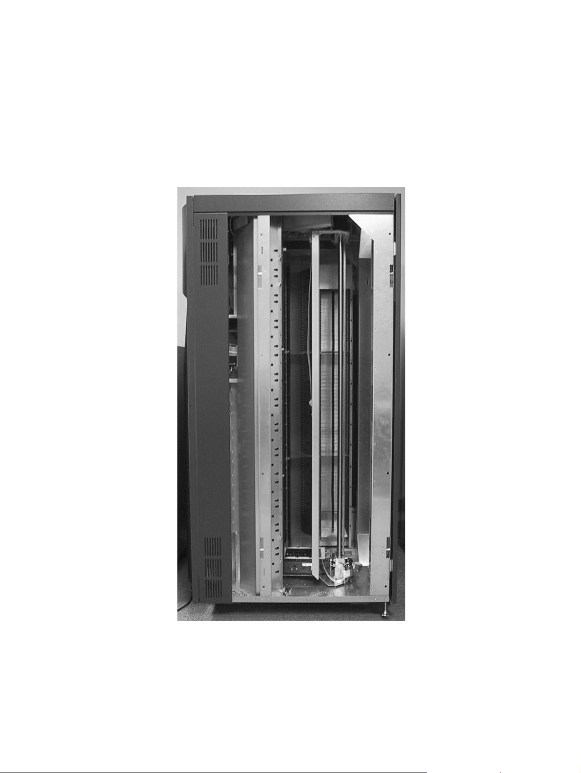
D1525 - D2175 Bay Installation
The expansion storage bays that attach to the sides of the Plasmon D875 library are shipped
separately. The following instructions explain how to mount the bays to the main library chassis.
Note: This operation should be performed by two people.
1. The main library chassis is shipped without side panels as shown below. Remove the
side panels if upgrading a standard D875 library to a D1525 and D2175.
Figure 10. Expansion Bay Installation (a)
Library Installation Plasmon D875 - D2175 User Manual
Page 24 Document Revision E
Page 27
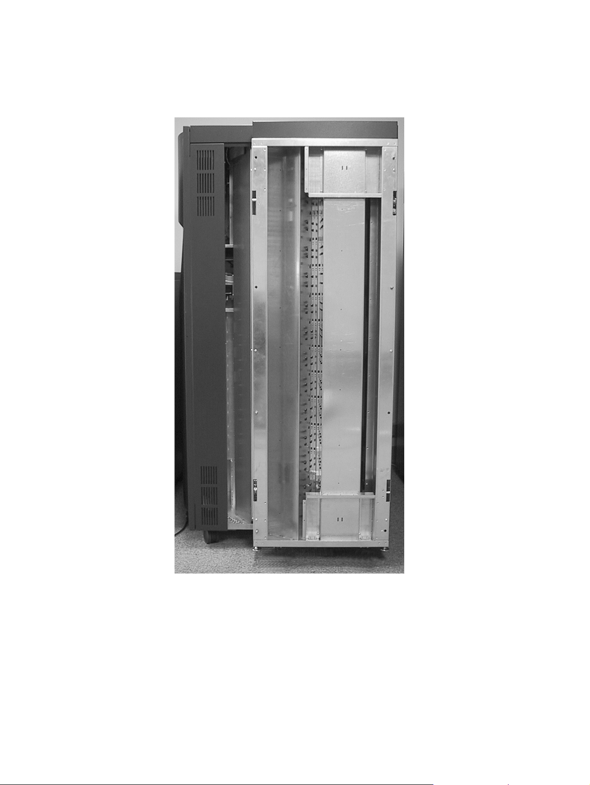
2. Position the expansion bay flush against the library chassis matching the guide pins on
the chassis to the guide holes on the expansion bay.
Figure 11. Expansion Bay Installation (b)
Plasmon D875 - D2175 User Manual Library Installation
Document Revision E Page 25
Page 28
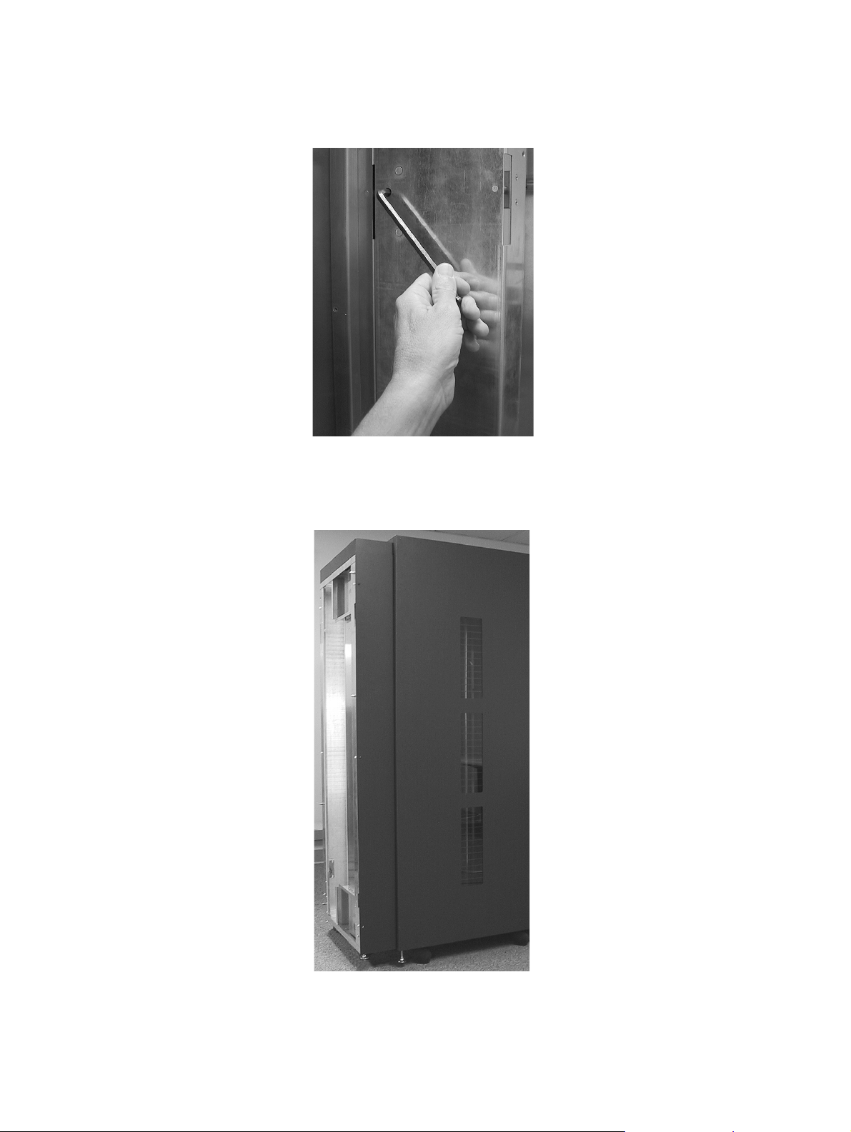
3. Using a 5/16 in hex wrench, engage the four latch hooks that hold the expansion bays to
the library chassis. There are two on each side of the bay.
Figure 12. Expansion Bay Installation (c)
4. Using a phillips head screw driver, attach the finish matching cover plate to the back side
of the expansion bay with the color coated screws provided.
Figure 13. Expansion Bay Installation (d)
Library Installation Plasmon D875 - D2175 User Manual
Page 26 Document Revision E
Page 29
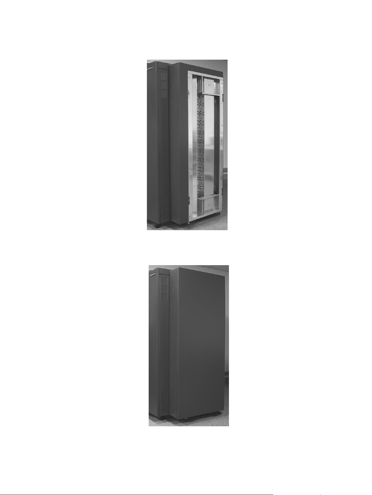
5. Attach the finish matching square column to the front of the bay by hanging it on the
screw heads provided.
Figure 14. Expansion Bay Installation (e)
6. Finally, attach the finish matching side panel to the bay by hanging it on the screw heads
provided.
Figure 15. Expansion Bay Installation (f)
Plasmon D875 - D2175 User Manual Library Installation
Document Revision E Page 27
Page 30
Library Packing Instructions
This section is provided in case it is necessary to ship the library (without expansion bays) to another
location or back to Plasmon. Instructions on how to pack the expansion bays is provided later in this
chapter. These procedures must be followed.
CAUTION
Plasmon libraries must be shipped in the original packaging.
Shipping a unit in anything other than the manufacturers
packaging voids the warranty. Replacement packaging is
available from Plasmon.
The library must be parked before packing the system.
Follow these steps to pack the library for shipping:
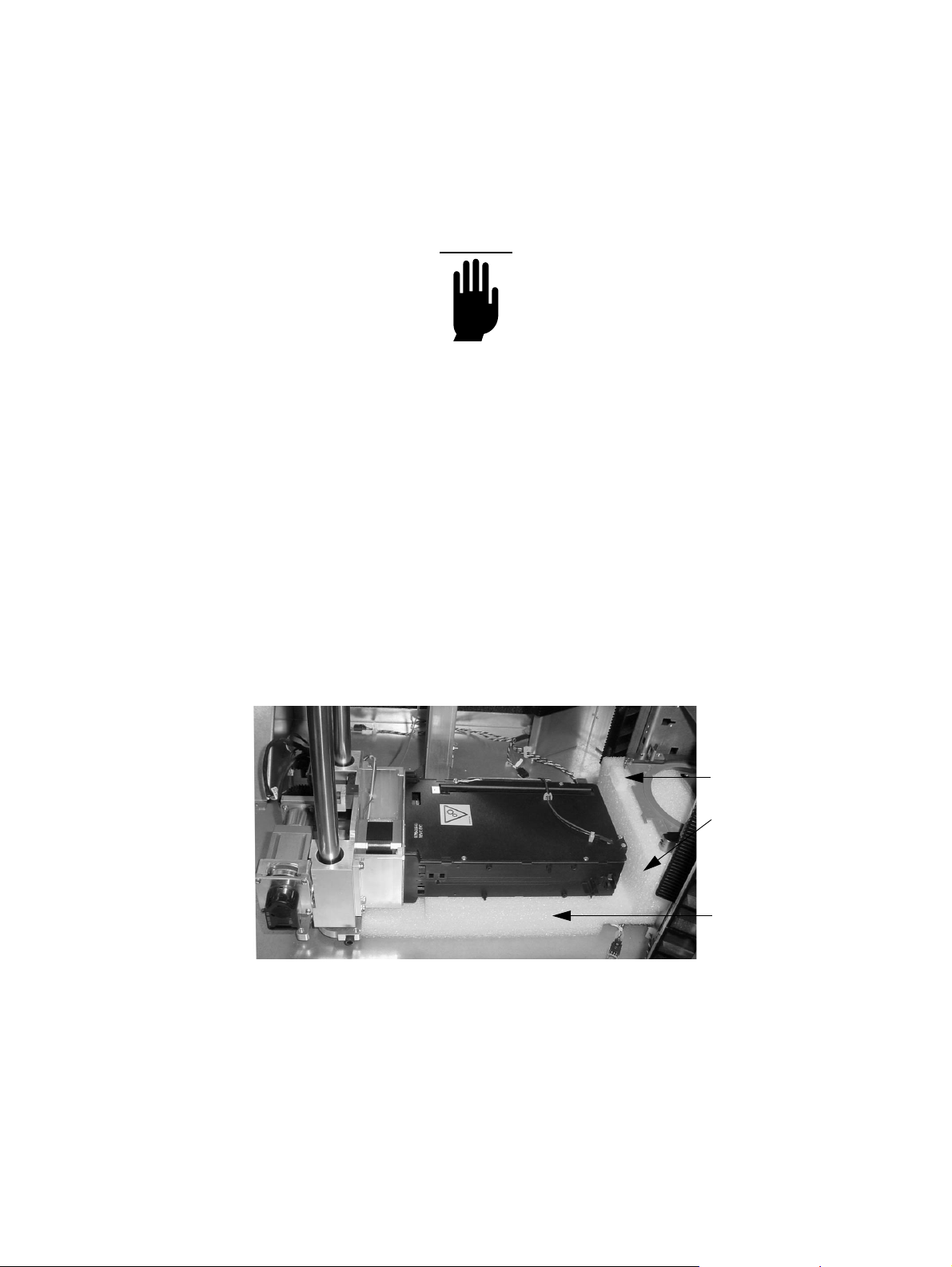
1. While parking, the library prompts for insertion of the MTE packaging material.
2. Insert the first piece of foam under the Rotation Station. Place this foam so the tab is on
the top left side when viewed from the back of the library.
3. Insert the second piece of foam under the MTE being careful not to damage the vertical
path emitter. Place this foam so the cut-out is on the left when viewed from the back of the
library.
Foam tab
1st Piece of
Packaging
Foam
2nd Piece of
Packaging
Foam
Figure 16. Packing the D875 - D2175 Libraries (a)
Library Installation Plasmon D875 - D2175 User Manual
Page 28 Document Revision E
Page 31
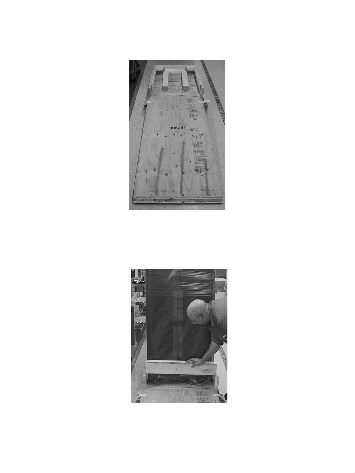
4. Place skid ramp on the ground in front of the packaging skid. Connect the velcro on the
ramp to velcro on packaging skid.
Figure 17. Packing the D875 - D2175 Libraries (b)
5. Roll the library onto packaging skid. The library’s front door goes onto skid first. Push on
bottom of library when rolling onto packaging skid.
6. Cover the library with the anti-static bag, and insert back edge-board into slots with foam
protected side toward library.
Figure 18. Packing the D875 - D2175 Libraries (c)
Plasmon D875 - D2175 User Manual Library Installation
Document Revision E Page 29
Page 32
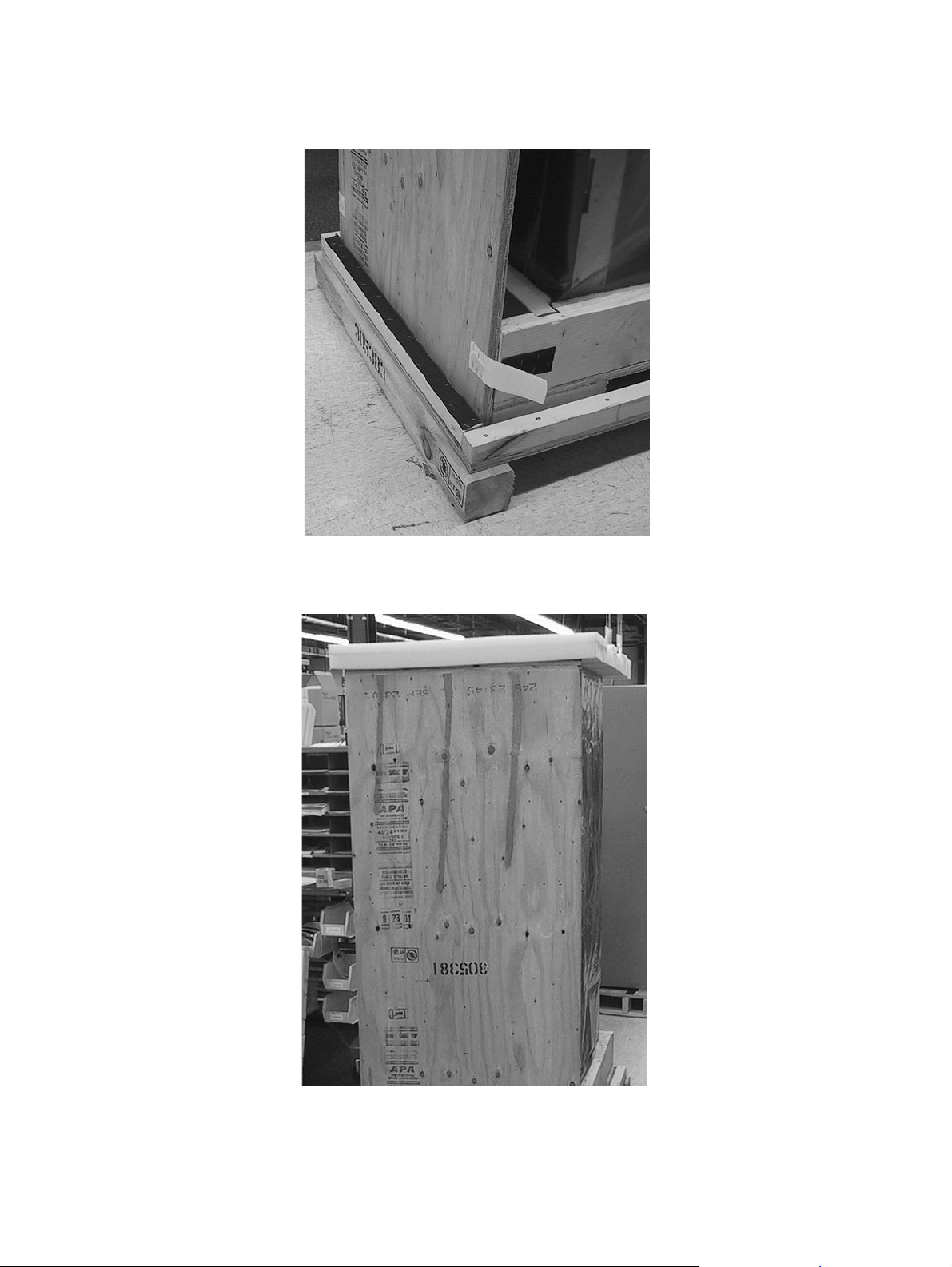
7. Remove ramp from skid and place upright in slot provided behind library. Close velcro
fasteners.
Figure 19. Packing the D875 - D2175 Libraries (d)
8. Place top foam over library, and fit in place.
Figure 20. Packing the D875 - D2175 Libraries (e)
Library Installation Plasmon D875 - D2175 User Manual
Page 30 Document Revision E
Page 33
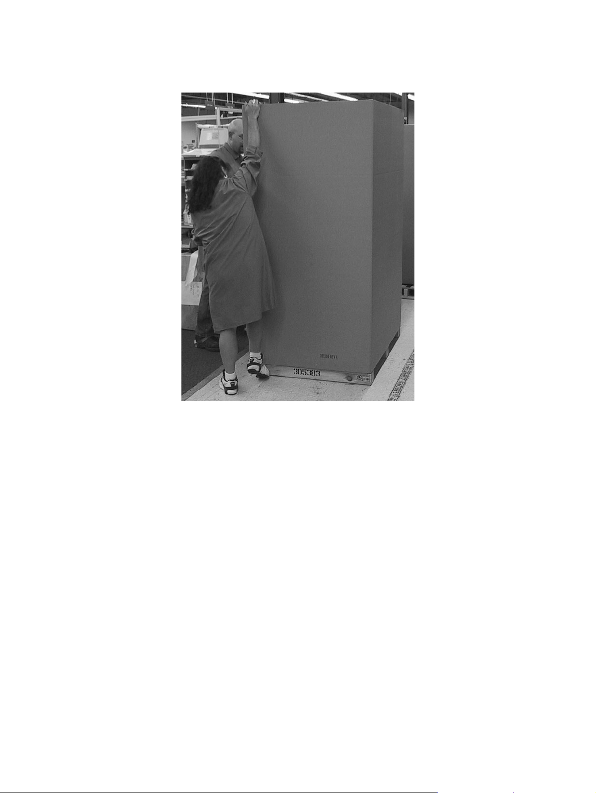
9. Place cardboard sleeve over library, and place lid on top.
Figure 21. Packing the D875 - D2175 Libraries (f)
10. Finally, strap box to the skid for shipping.
Plasmon D875 - D2175 User Manual Library Installation
Document Revision E Page 31
Page 34
Packing Instructions (D1525 - D2175 Expansion Bays)
This section is provided in case it is necessary to ship the bays to another location, or back to
Plasmon. These procedures must be followed.
CAUTION
Plasmon libraries and bays must be shipped in the original
packaging. Shipping a unit in anything other than the
manufacturers packaging voids the warranty. Replacement
packaging is available from Plasmon.
Follow these steps to pack the bays for shipping:
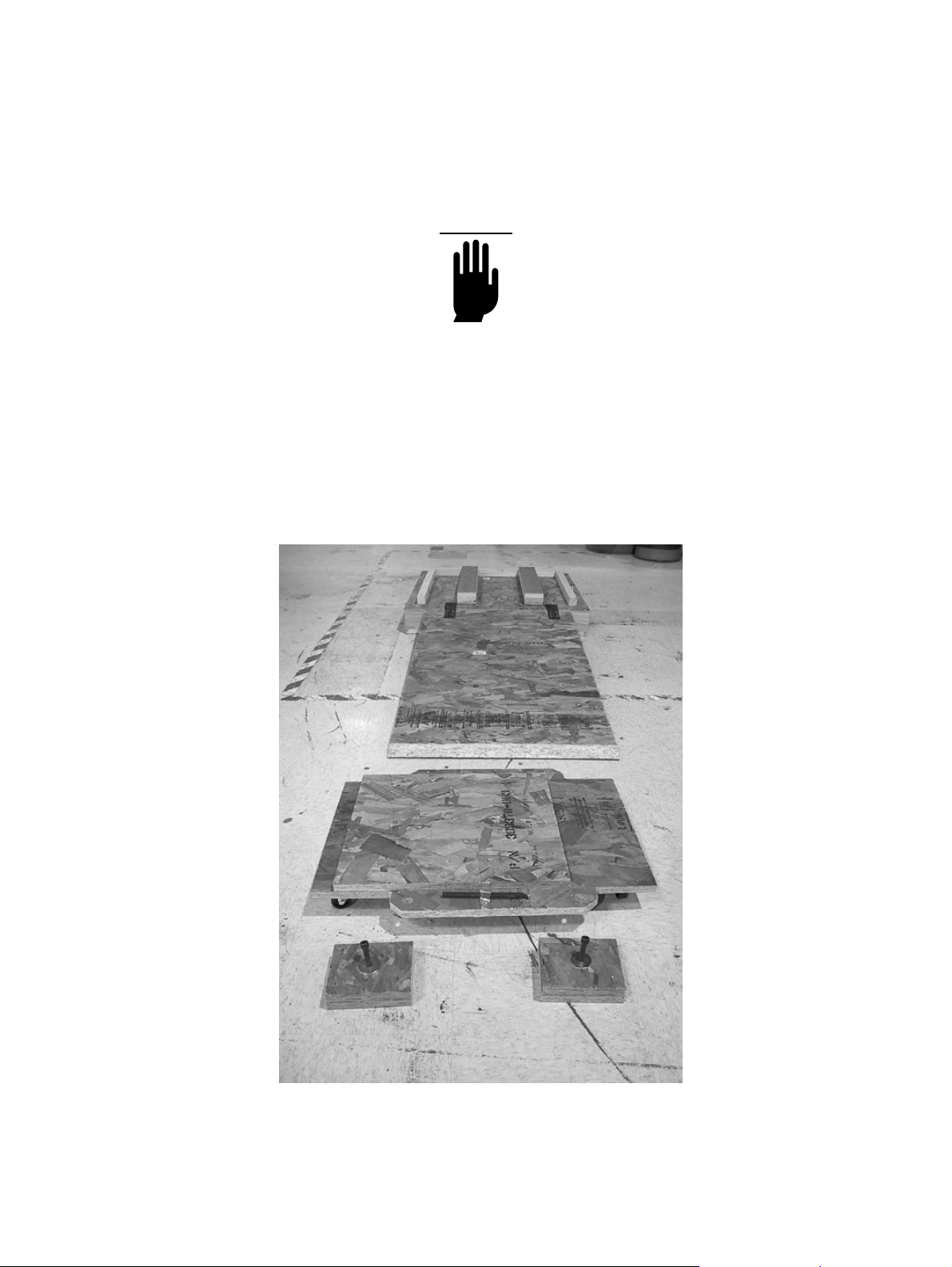
1. Lay out the pallet & ramp, wheeled skid, and mounting blocks as shown in the picture
below. Ensure the ramp is securely attached to the pallet with the velcro strips.
Figure 22. Expansion Bay Packing (a)
Library Installation Plasmon D875 - D2175 User Manual
Page 32 Document Revision E
Page 35
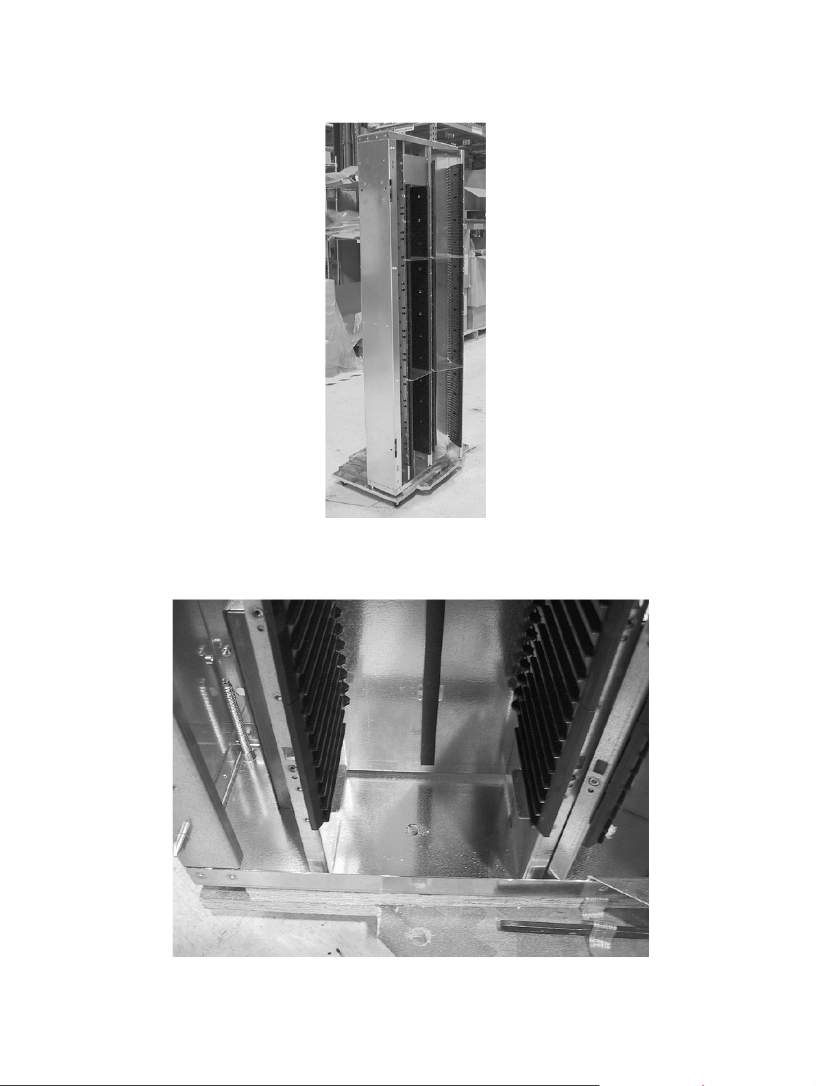
2. Place the first bay on the wheeled skid as shown in the picture below.
Figure 23. Expansion Bay Packing (b)
3. Position the bay so the mounting bolt hole lines up as shown below.
Figure 24. Expansion Bay Packing (c)
Plasmon D875 - D2175 User Manual Library Installation
Document Revision E Page 33
Page 36
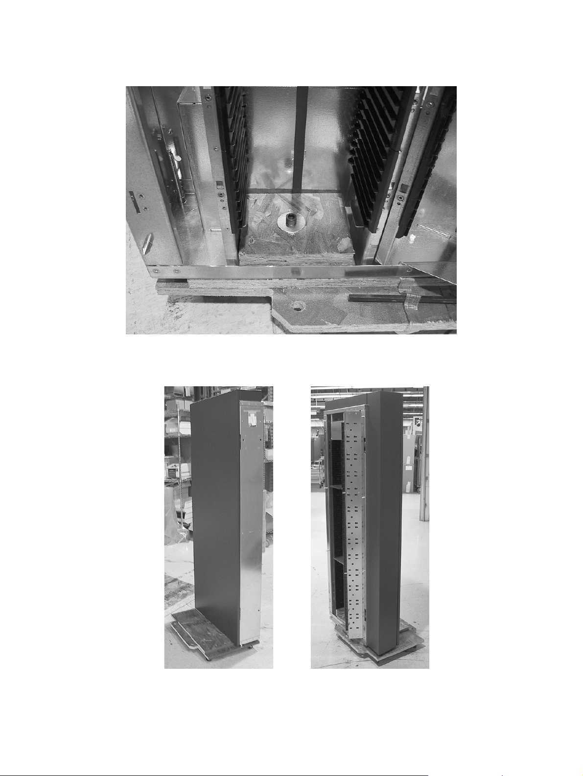
4. Use a mounting block and a hex head bolt to secure the bay to the wheeled skid.
Figure 25. Expansion Bay Packing (d)
5. Hang the painted skin and spacer column on their mounting screws as shown.
Figure 26. Expansion Bay Packing (e)
Library Installation Plasmon D875 - D2175 User Manual
Page 34 Document Revision E
Page 37
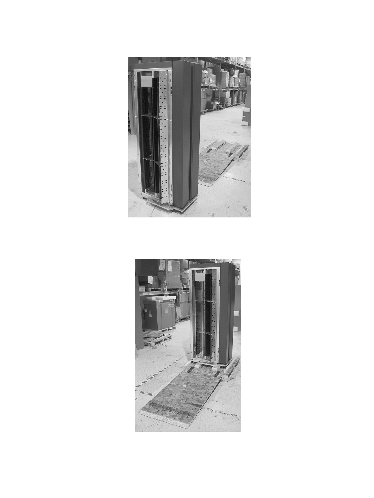
6. Secure a second bay in the same way, but facing the opposite direction.
Figure 27. Expansion Bay Packing (f)
7. With two people steadying the bays, roll the wheeled skid up the ramp onto the pallet.
Push at the bottom to avoid tipping.
Figure 28. Expansion Bay Packing (g)
Plasmon D875 - D2175 User Manual Library Installation
Document Revision E Page 35
Page 38
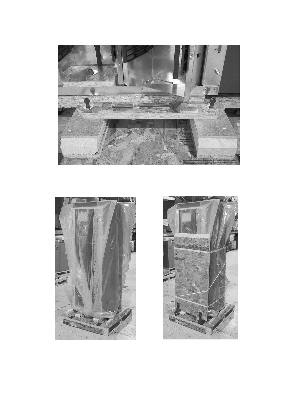
8. Secure the wheeled skid to the pallet with four hex head bolts (two on each side).
Figure 29. Expansion Bay Packing (h)
9. Cover each bay with an anti-static bag, and tape the ramp in an upright position as
shown.
Figure 30. Expansion Bay Packing (i)
Library Installation Plasmon D875 - D2175 User Manual
Page 36 Document Revision E
Page 39
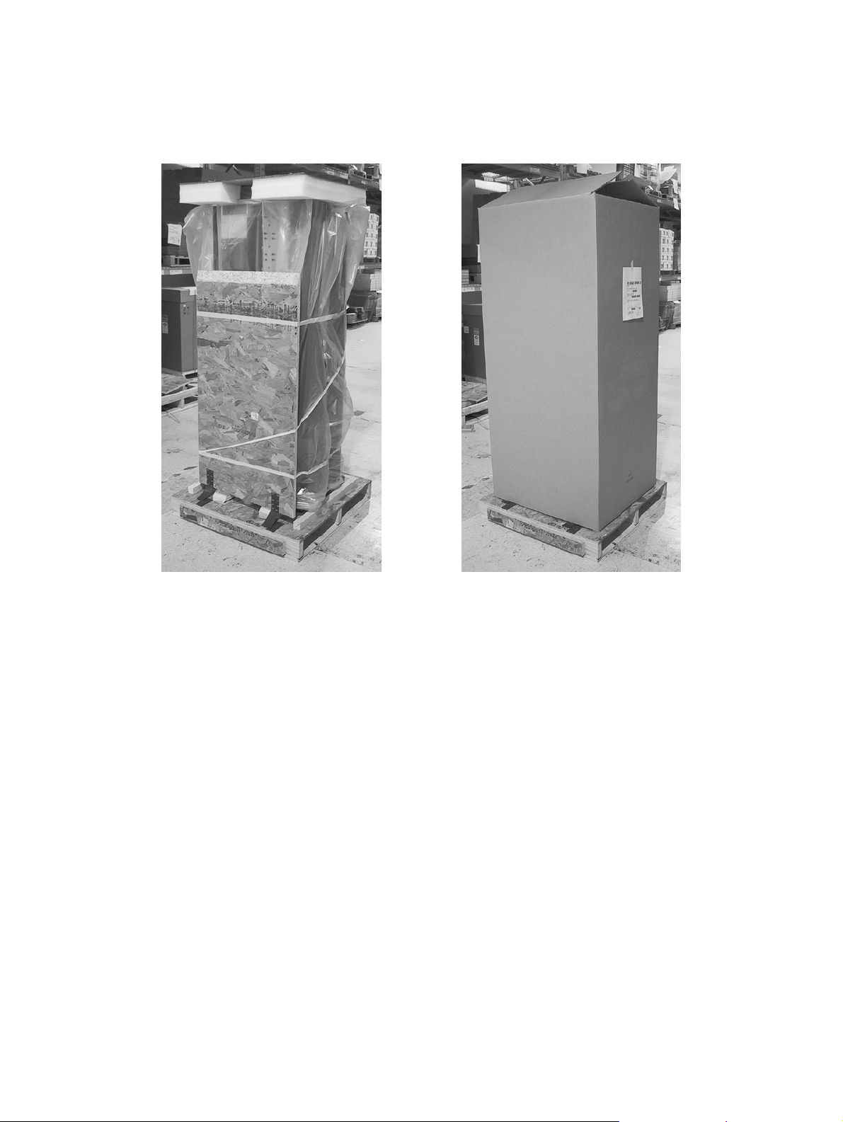
10. Place the shaped foam topper on the bays. Make certain the center spacer foam fits
down between the bays. Then slid the cardboard box over the bays and tape the top flaps
closed.
Figure 31. Expansion Bay Packing (j)
11. Finally, strap box to skid for shipping.
Plasmon D875 - D2175 User Manual Library Installation
Document Revision E Page 37
Page 40

Library Installation Plasmon D875 - D2175 User Manual
Page 38 Document Revision E
Page 41
CHAPTER 3
MENU SYSTEM
Navigating the Menu System
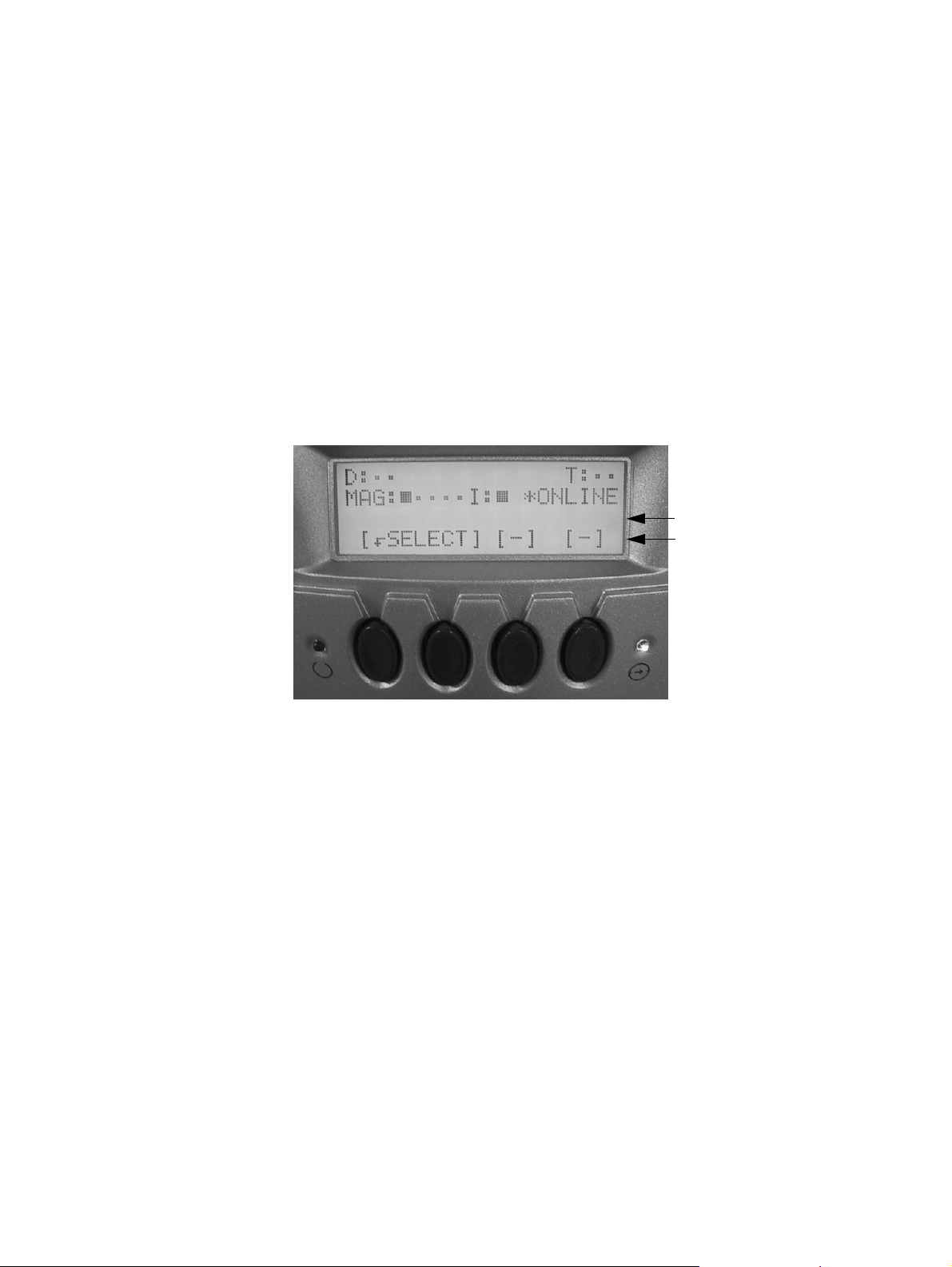
The Plasmon D-Series library modes and functions are controlled using four selection buttons located
on the front panel display. A liquid crystal display (LCD) located directly above the buttons, provides
system status and other important information.
Description Line
Selection Button Indicators
Figure 32. LCD Display Format
The description line displays the number and name of the mode or test when navigating menus. An
ellipsis (...) following a name indicates that the selection contains submenus.
The selection button indicators display the function of the four buttons located directly below the
indicators. A dash above a button means that no function is associated with this key. The following
LCD Symbols table provides an explanation of each symbol.
Plasmon D875 - D2175 User Manual Menu System
Document Revision E Page 39
Page 42
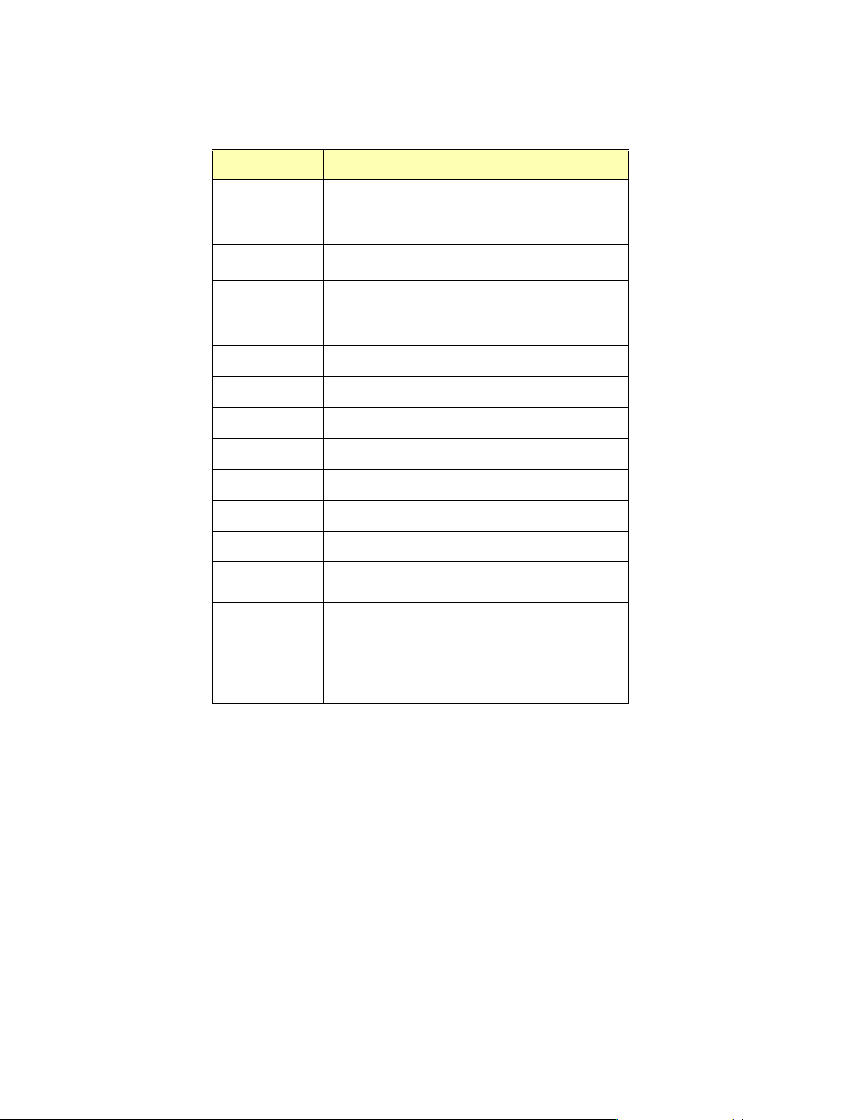
Table 5. LCD Symbols
LCD symbol Meaning
H
F
A
Z
B
V
U
N
M
D
R
z
Enter a menu selection
Exit a menu selection
Change a mode selection
Switch to display scroll mode
Confirm a selection
Decrement a numeric value or scroll display up
Increase a numeric value
Go to the previous menu item
Go to the next menu item
Display a list of menu items
Run a motor or execute a function
X
Indicates a drive is turned off
Indicates media exists in an element
—
Indicates magazine exists in an element
•
Indicates the element is empty
Indicates an empty tray in a drive
Menu System Plasmon D875 - D2175 User Manual
Page 40 Document Revision E
Page 43
Power Up Menu Options
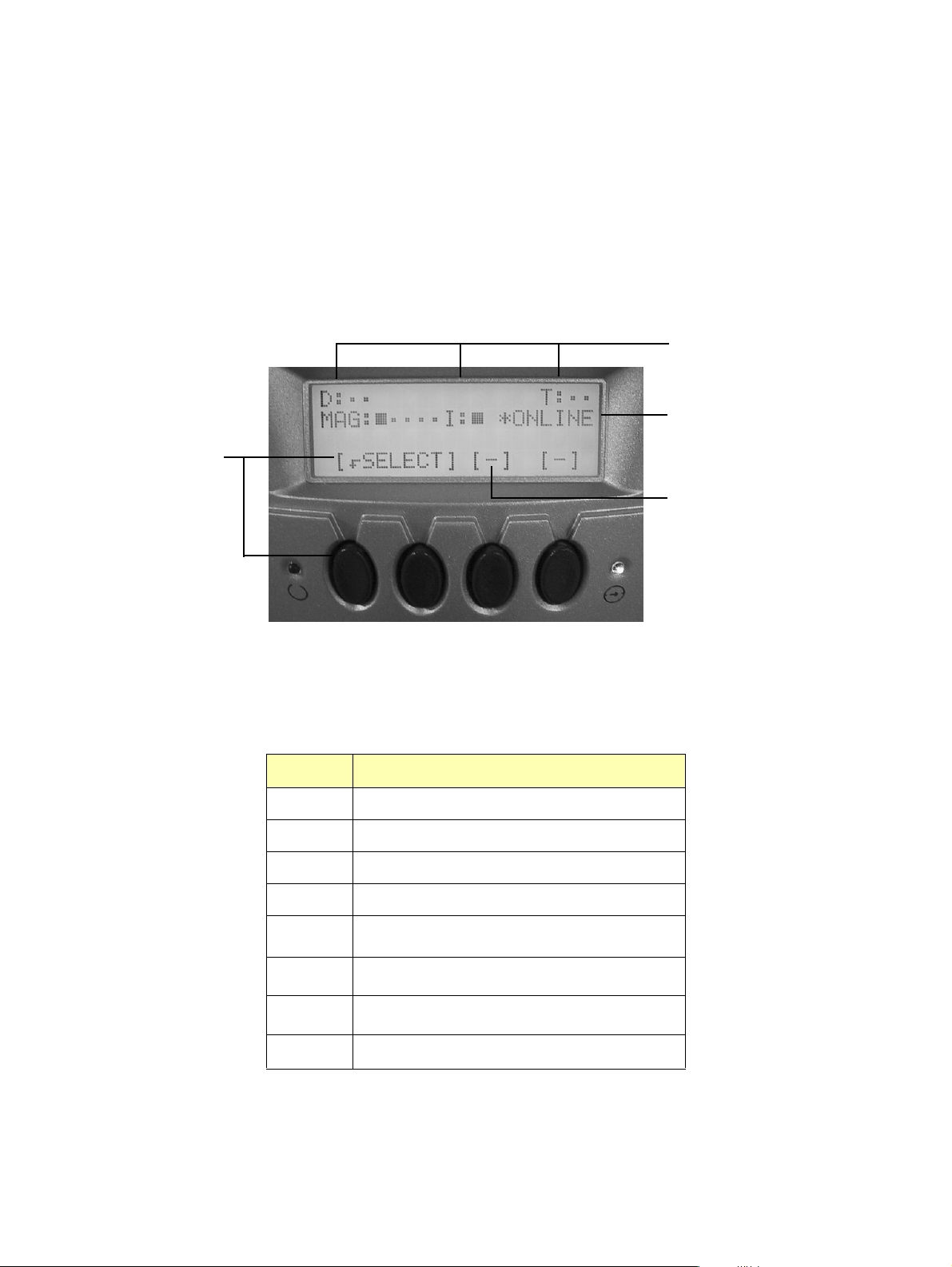
The following operations can be performed at the initial power up stage:
• Entering the library’s main menu system.
• Viewing error information.
When the library powers up, the LCD displays:
Pressing the button
below SELECT
displays the main
menu functions
Displays element status
information as described
in the table below
Displays Error xx if an
error occurs
Displays C when an error
occurs
Figure 33. Power Up LCD Display
Table 6. Power Up LCD Symbols
Symbol Meaning
D
T
I
MAG
•
z
—
Drive status (drive present, media present)
Media Transport Element status (media present)
I/E Port status (magazine present)
Ten Slot Magazine slot status (magazine present)
Empty element
Media in element
Magazine in element
Empty tray in drive
Plasmon D875 - D2175 User Manual Menu System
Document Revision E Page 41
Page 44
Main Menu Overview
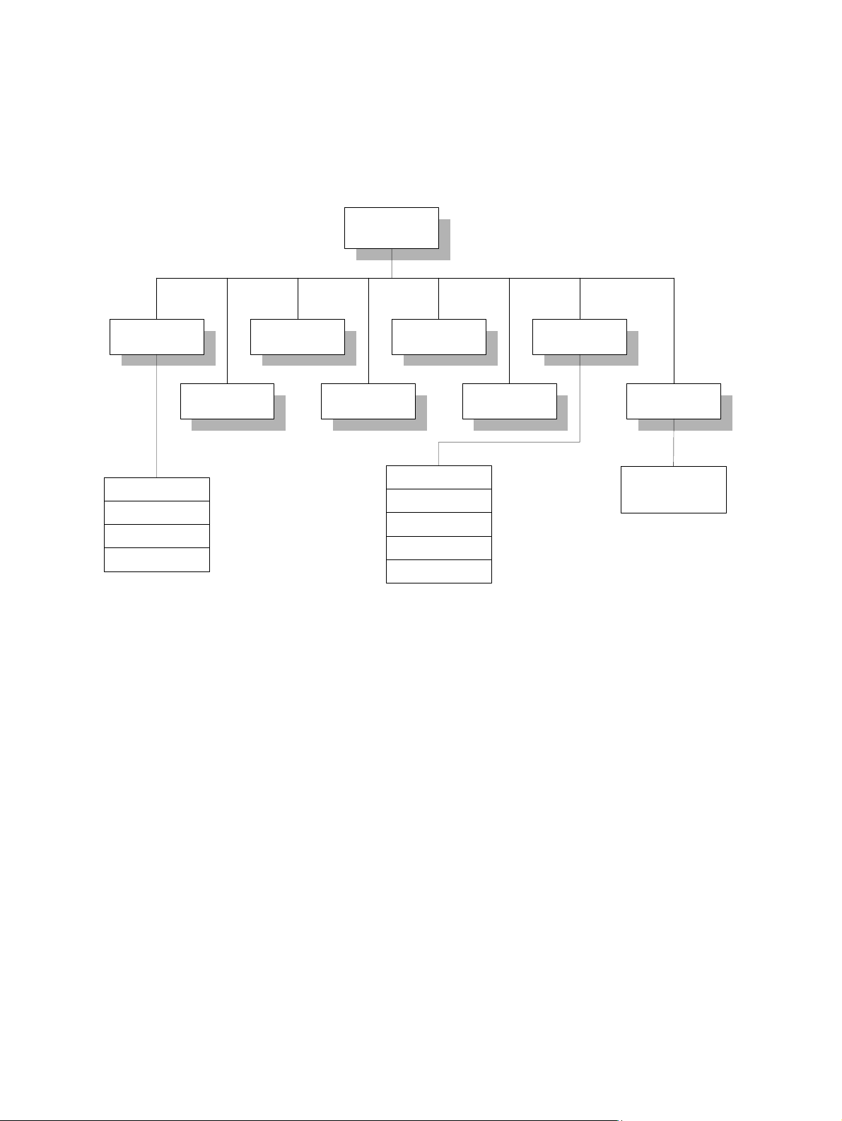
The D875 - D2175 library LCD menu system starts with nine top-level options. To cycle through the
options at any level press
1 Library Status 3 Turn Drive Off 5 Service Drive 7 Setup Library
[DSELECT]. To enter a selection press [
Select Menu
H
].
1 Config Information
2 Status Information
3 Error Information
4 Network Interface
2 Exchange
Magazines
4 Turn Drive On
1 Config Information
2 Status Information
3 Error Information
4 Network Interface
5 Off-line Operations
6 Restore Drive
8 Maintenance
Mode
Reserved for
Plasmon Trained
Service Personnel
Figure 34. Main Menu Overview
Menu System Plasmon D875 - D2175 User Manual
Page 42 Document Revision E
Page 45
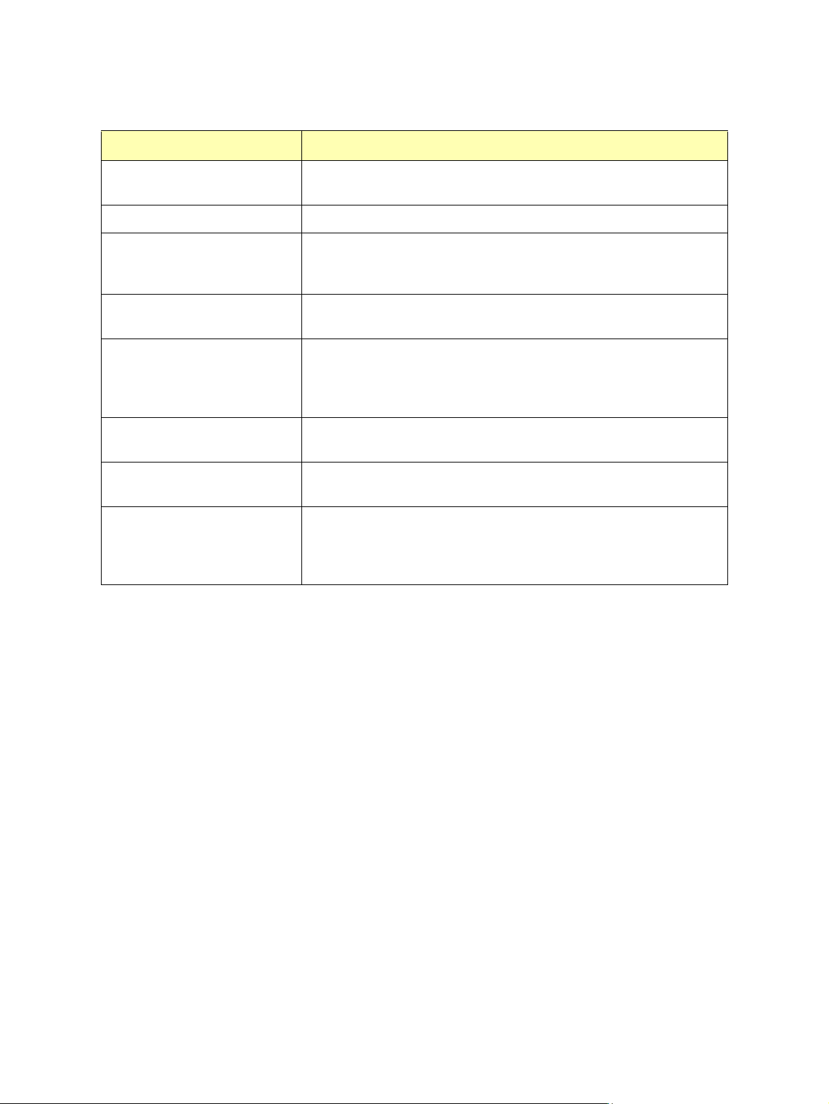
Table 7. Main Menu Selections
Menu Selection Description
1 Library Status Allows viewing only of library settings. To make changes, use the Set Up
menu.
2 Exchange Magazines Use to release the magazine from the library.
3 Turn Drive Off Use to turn off individual drives. Drives may not be hot-swapped in this
mode. For password protected operations, the factory default password is
"AAAA".
4 Turn Drive On Use to turn on individual drives. For password protected operations, the
factory default password is "AAAA".
5 Service Drives Use to remove power from the drive to allow removal or replacement. This
option takes down the entire SCSI bus the drive is on, and all drives associated with this bus loose SCSI access. For password protected operations,
the factory default password is "AAAA".
6 Restore Drives Use to restore power to the drives after removal or replacement. For pass-
word protected operations, the factory default password is "AAAA".
7 Set Up Library Allows viewing and changing of library settings. When performing opera-
tions from the Set Up menu, the library is taken off-line.
8 Maintenance Mode Allows testing, setting up, or configuring the library. When performing oper-
ations from the Maintenance Mode menu, the library is taken off-line. These
operations are reserved for Plasmon authorized service personnel. For
password protected operations, the factory default password is “AAAA”.
Plasmon D875 - D2175 User Manual Menu System
Document Revision E Page 43
Page 46
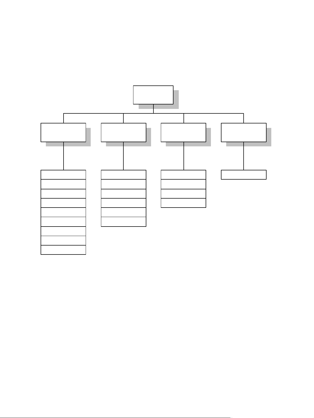
Library Status Menu Overview
Use the Library Status menu to view the library’s status only. To make changes to the library’s status,
use the Set Up menu.
The figure below shows the Library Status menu options.
1 Library Status
3 Error Information2 Status Inf ormation 4 Network Interface1 Conf ig Information
1 Unit Inf ormation
2 Serial Number
3 Dat e and Time
4 SCSI Bus C onf ig
5 Changer Addres s
6 Driv e Address es
7 Changer Options
8 Pass words
9 RMI Information
1 Error Log
2 Driv e States
3 Power-On Hours
4 Unit Cycle Count
5 Driv e Load Counts
6 Func tion Counts
2 Error St atis tic s
3 Ev ent History
4 Micro-Op Stac k
Figure 35. Library Status Menu Options
Not Used1 Element Stat us
Menu System Plasmon D875 - D2175 User Manual
Page 44 Document Revision E
Page 47
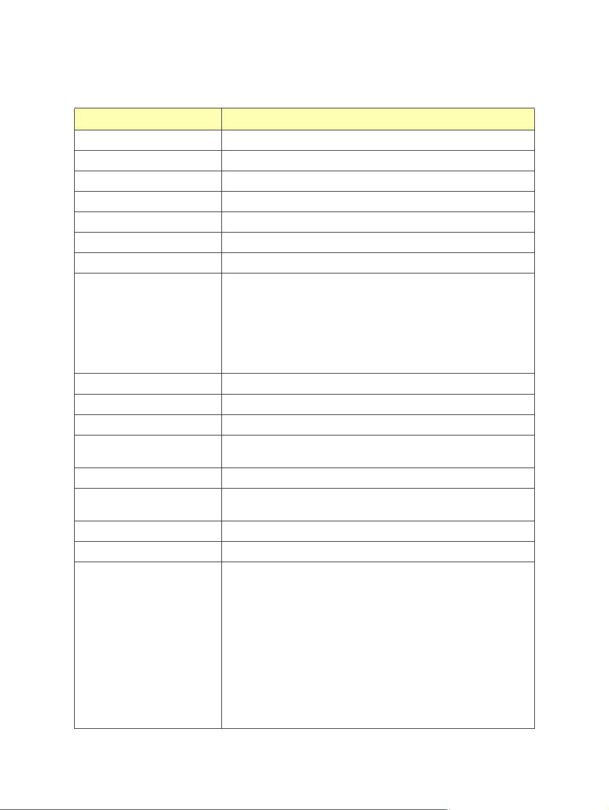
Table 8. Library Status Menu Selections
Menu Selection Description
1 Config Information Allows viewing only of library configuration settings.
1 Unit Information/Config
2 Serial Number
3 Date and Time
4 SCSI Bus Config
5 Changer Address
6 Drive Addresses
7 Changer Options
8 Passwords
9 RMI Information
2 Status Information Allows viewing only of library status.
1 Element Status
To view the storage slot count, drive count, and firmware revision.
To view the serial number assigned to the library.
To view the current date and time settings.
To view the current SCSI Bus configuration
To view the changer SCSI ID.
To view individual drive SCSI IDs.
To view changer options:
Disable Tray Return (default Y or N)
Tray Return on Power (Y or default N)
Disable Autoload/Eject (Y or default N)
Ignore Recovery Errors (Y or default N)
Limit Recovery (Y or default N)
Enable All Uattn (Y or default N)
This option is not available when library is online.
Not supported.
To view which elements (slots, drives, pickers, or I/E station) are populated
by media.
2 Drive States
3 Power-On Hours
4 Unit Cycle Count
5 Drive Load Counts
6 Function Counts
Plasmon D875 - D2175 User Manual Menu System
Document Revision E Page 45
To view the power on/off state of a drive.
To view total hours of power to library. Useful for preventive maintenance.
Cannot be reset.
To view total cycle count since first startup. Cannot be reset.
To view total drive loads since last reset of count.
To view total function counts since last reset of count.
Lift Movement Count
Picker 1 Movement Count
Picker 2 Movement Count
Change Picker Count
Pivot L/R Col Movement Count
Mag Door Open Count
Disk Flip Count
Cumul Lift Dist
Cumul Picker Dist
Cumul Pivot Rotation
Page 48
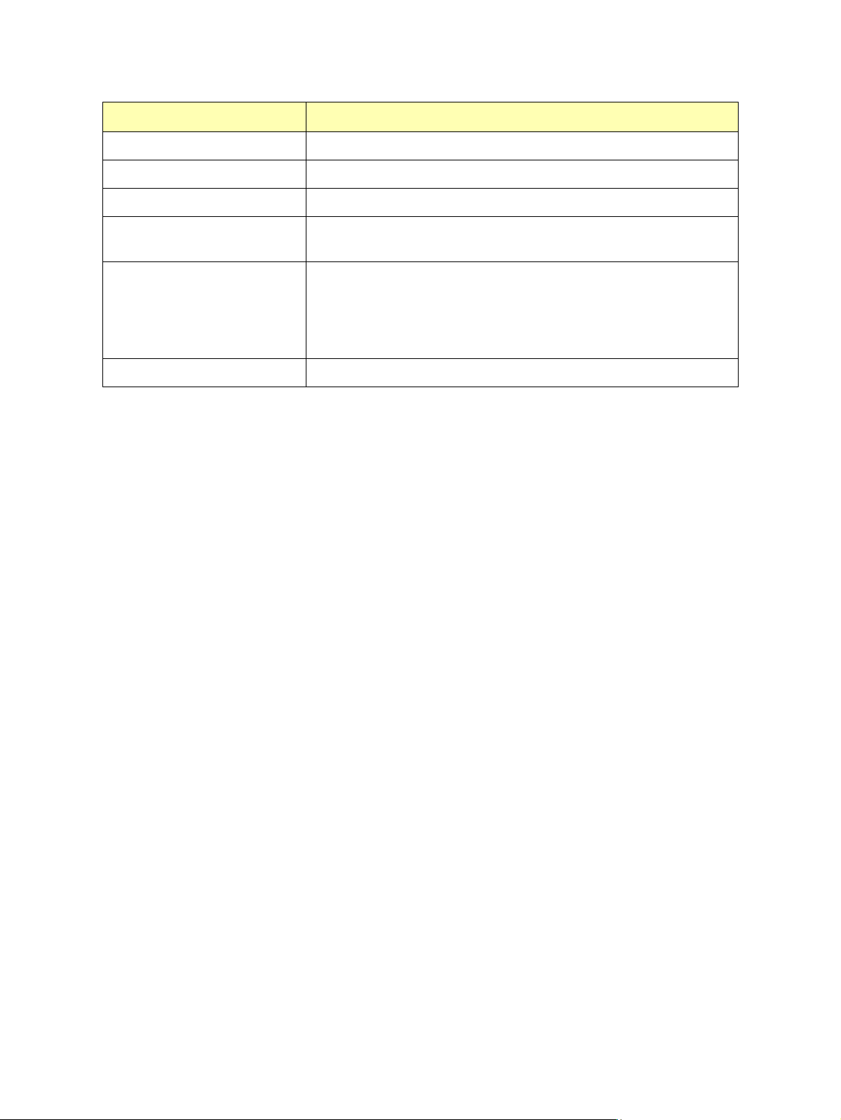
Menu Selection Description
3 Error Information Allows viewing only of library error information.
1 Error Log
2 Error Statistics
3 Event History
4 Micro-Op Stack
4 Network Interface Not Used.
To view a chronological list of last ten errors since log was last cleared.
To view a list of the ten most frequent errors since list was last cleared.
To view the SCSI command event history since it was last reset. Only SCSI
commands which affect library operations are recorded.
To view a list of operations performed for the last failing SCSI command.
These micro operations include position, position and flip, pick, store, load,
and unload. The list includes forward and backward operations (media
movement, and undo and retry for attempted failure recovery). This log is
cleared whenever the system is initialized.
Menu System Plasmon D875 - D2175 User Manual
Page 46 Document Revision E
Page 49
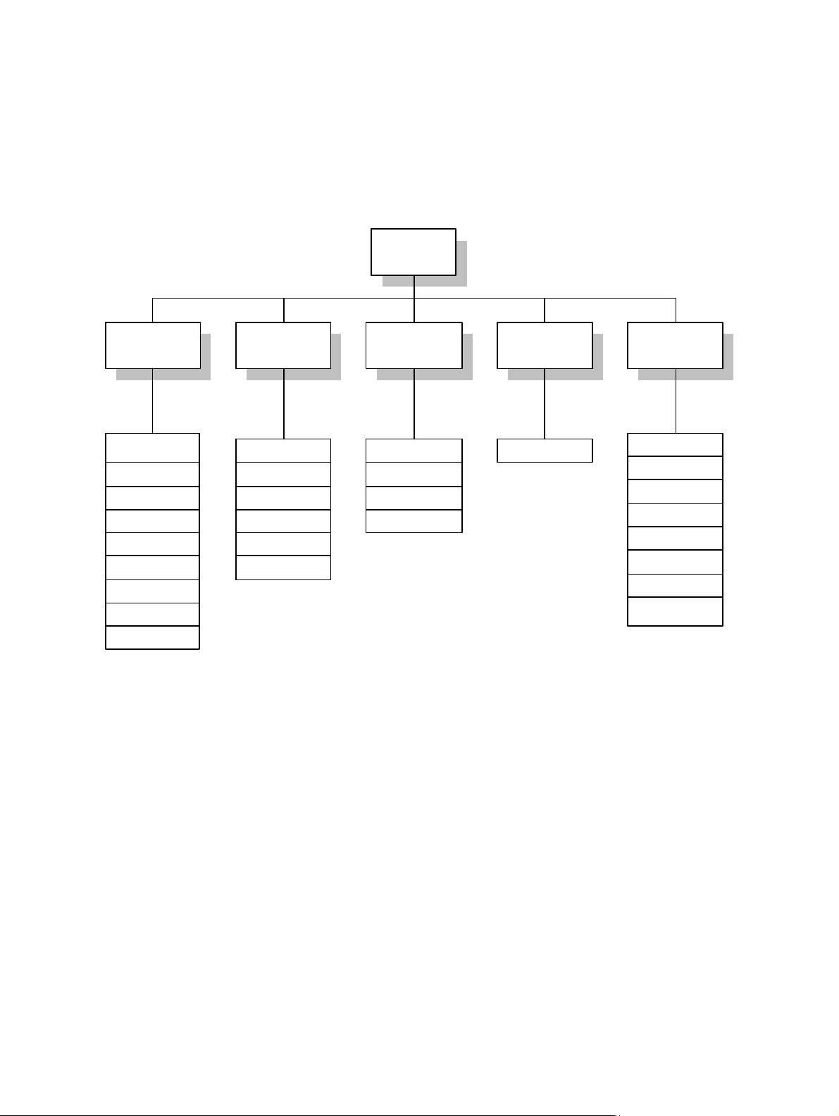
Set Up Library Menu Overview
Use the Set Up Library menu to change the library’s status. When performing operations in the Set Up
Library menu, the library is taken off-line.
The figure below shows the Set Up Library menu options.
7 Set U p Li br ar y
3 Error Information2 Status Information 5 Offl i ne Oper at i ons4 Network Interface1 Config Information
1 Unit Info/Config
2 Ser i al Number
3 Dat e and Ti me
4 SCSI Bus Confi g
5 Chang er Addr ess
6 Dr i ve Addr es ses
7 Chang er Opti ons
8 Pass words
9 RMI Information
2 Dr i ve Stat es
3 Power- On Hour s
4 Uni t Cycle Count
5 Dr i ve Load C ounts
6 Func ti on C ounts
Figure 36. Set Up Library Menu Options
1 Error Log
2 Error Statistics
3 Event Hi s tor y
4 Mi c r o- Op Stack
Not Used1 Element Status
1 Res can El ements
2 Retur n al l T r ays
3 Par k Libr ar y
4 Tes t Libr ar y
5 Ser vic e Dr i ves
6 Res tor e Dr i ves
7 Bulk Load Li br ary
8 Bulk Unload Li br ar y
Plasmon D875 - D2175 User Manual Menu System
Document Revision E Page 47
Page 50
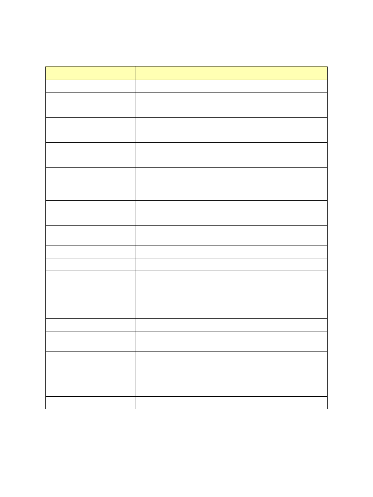
Table 9. Set Up Library Menu Selections
Menu Selection Description
1 Config Information Allows viewing and editing of library configuration settings.
1 Unit Information/Config
2 Serial Number
3 Date and Time
4 SCSI Bus Config
5 Changer Address
6 Drive Addresses
7 Changer Options
Disable Tray Return
Tray Return On Power
Disable Auto LD/EJ
Ignore Recover Errs
Limit Recovery
Enable All UATTN
8 Passwords
To view the storage slot count, drive count, and firmware revision.
To view the serial number assigned to the library.
To view/edit the current date and time settings.
To view the current SCSI bus configuration.
To view/set the changer SCSI ID.
To view/set individual drive SCSI IDs.
To view/edit changer options:
Disables return of media trays to their magazines when entering Magazine
Exchange mode.
Enables the return of media trays to the magazines upon library power on.
Disables auto clamping and unclamping of the media tray.
If library can recover from an error, it will keep operating and not report the
error.
To limit error recovery effort to four tries.
Enable all unit attention conditions to host.
To set or change passwords. To remove password protection from a menu
selection, press the check mark without entering any letters. The factory
default password is AAAA. If a password is forgotten or lost, please contact
Plasmon support.
9 RMI Information
2 Status Information Allows viewing/editing of library status.
1 Element Status
2 Drive States
3 Power-On Hours
4 Unit Cycle Count
5 Drive Load Counts
Menu System Plasmon D875 - D2175 User Manual
Page 48 Document Revision E
Not supported.
To view/edit which elements (slots, drives, pickers, or I/O stations) are populated by media trays. Individual slot status can be set to full or empty.
To view a drive’s on/off state.
To view total hours of power to library. Useful for preventive maintenance.
Cannot be reset.
To view total cycle count since first startup. Cannot be reset.
To view/reset total drive loads since last reset of count.
Page 51
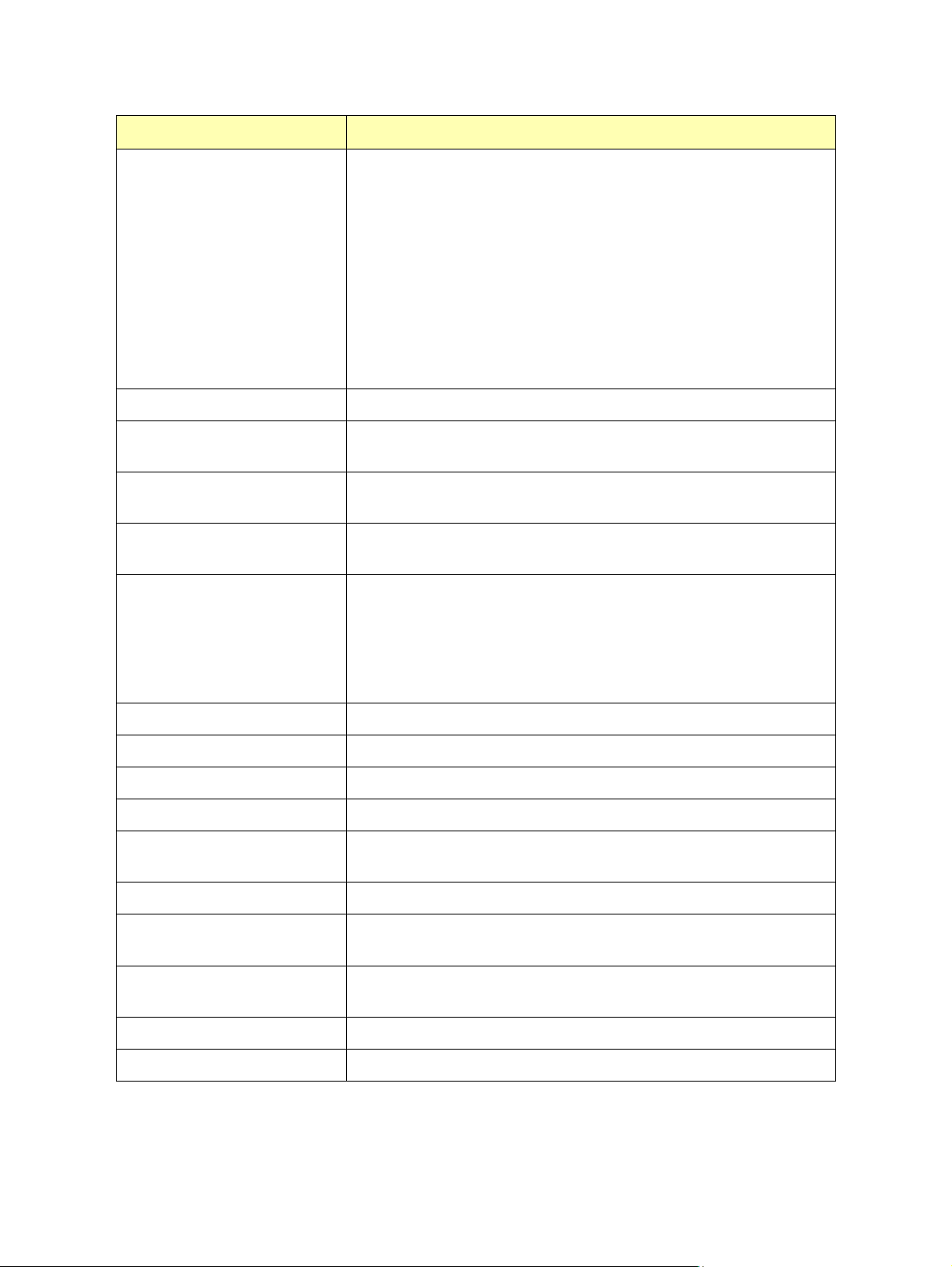
Menu Selection Description
6 Function Counts
3 Error Information Allows viewing/clearing of library error information.
1 Error Log
2 Error Statistics
3 Event History
4 Micro-Op Stack
To view/reset total function counts since last reset of count.
Lift Movement Count
Picker 1 Move Count
Picker 2 Move Count
Change Picker Count
Pivot Col Move Count
Mag Door Open Count
Disk Flip Count
Cumul Lift Dist
Cumul Picker Dist
Cumul Pivot Rotation
To view/clear a chronological list of last ten errors since log was last
cleared. The first on the list is the most recent.
To view/clear a list of the ten most frequent errors since list was last
cleared.
To view/clear the SCSI command event history since it was last reset. Only
SCSI commands which affect library operations are recorded.
To view a list of operations performed for the last failing SCSI command.
These micro operations include position, flip, pick, store, load, and unload.
The list includes forward and backward operations (media movement, and
undo and retry for attempted failure recovery). This log is cleared whenever
the system is initialized. This error should be reported to Plasmon for
decoding.
4 Network Interface Not Used.
5 Offline Operations Allows basic offline operations.
1 Rescan Elements
2 Return All trays
3 Park Library
4 Test Library
5 Service Drives
6 Restore Drives
7 Bulk Load Library
8 Bulk Unload Library
Plasmon D875 - D2175 User Manual Menu System
Document Revision E Page 49
Scans all storage slots and drives to identify media present.
Returns all magazine trays to their magazines.
To park the picker before shipping or moving the library. Also, remove all
media before moving the library.
To perform basic sensor and motor tests.
To turn a drive off and temporarily terminate the SCSI bus for drive replacement.
To turn a drive on and remove temporary SCSI bus termination after drive
replacement.
Allows initial high speed bulk loading of required media.
Allows unloading the entire library for packing and shipping.
Page 52

Menu System Plasmon D875 - D2175 User Manual
Page 50 Document Revision E
Page 53
APPENDIX A
SPECIFICATIONS
Overall Library Specifications
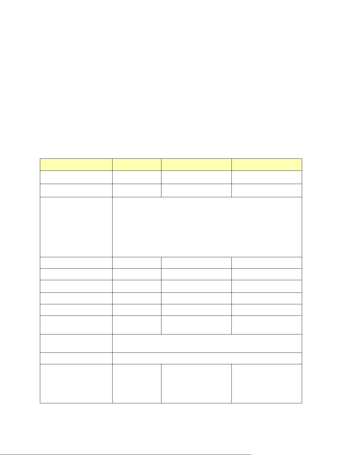
The following table provides information about the Plasmon D875 - D2175 libraries. These
specifications are subject to change without notice.
Table 10. D875 - D2175 Specifications
Specification D875 D1525 D2175
Number of Storage Slots
Library Capacity (TBytes)
Media Transport Times:
Swap Times
Flip every other access
Flip one way
Exchange Times
Flip 1/2 time
No Flip
Maximum Number of Drives 12 12 12
Library Reliability (MSBF) >2,500,000 >2,500,000 >2,500,000
Rotation Station
Picker Type Dual Dual Dual
Import / Export Port Ten-Slot Magazine Ten-Slot Magazine Ten-Slot Magazine
Removable Storage Slots Five Ten-Slot
Library Interface LVD (Auto - Sensing), SCSI 2 and SCSI 3 Compliant
TM
1
1
Never Flip
750 - 875 1400 - 1525 2050 - 2175
7.1 - 8.2 13.1 - 14.3 19.2 - 20.4
15.3 seconds / 235 swaps per hour
11.9 seconds / 302 swaps per hour
8.5 seconds / 425 swaps per hour
9.8 seconds
6.39 seconds
Standard Standard Standard
Five Ten-Slot
Magazines
68-pin high density female connector
Magazines
Five Ten-Slot
Magazines
Warranty 1 Year (First year on-site 5X9 next business day)
Dimensions - Stand Alone
Height
Width
Depth
Weight
Plasmon D875 - D2175 User Manual Appendix A
Document Revision E Page 51
68 in (172.3 cm)
27.2 in (69.1 cm)
36 in (91.4 cm)
491 lbs (223 kgs)
68 in (172.3 cm)
35 in (89 cm)
36 in (91.4 cm)
631 lbs (286 kgs)
68 in (172.3 cm)
41.2 in (105 cm)
36 in (91.4 cm)
771lbs (350 kgs)
Page 54
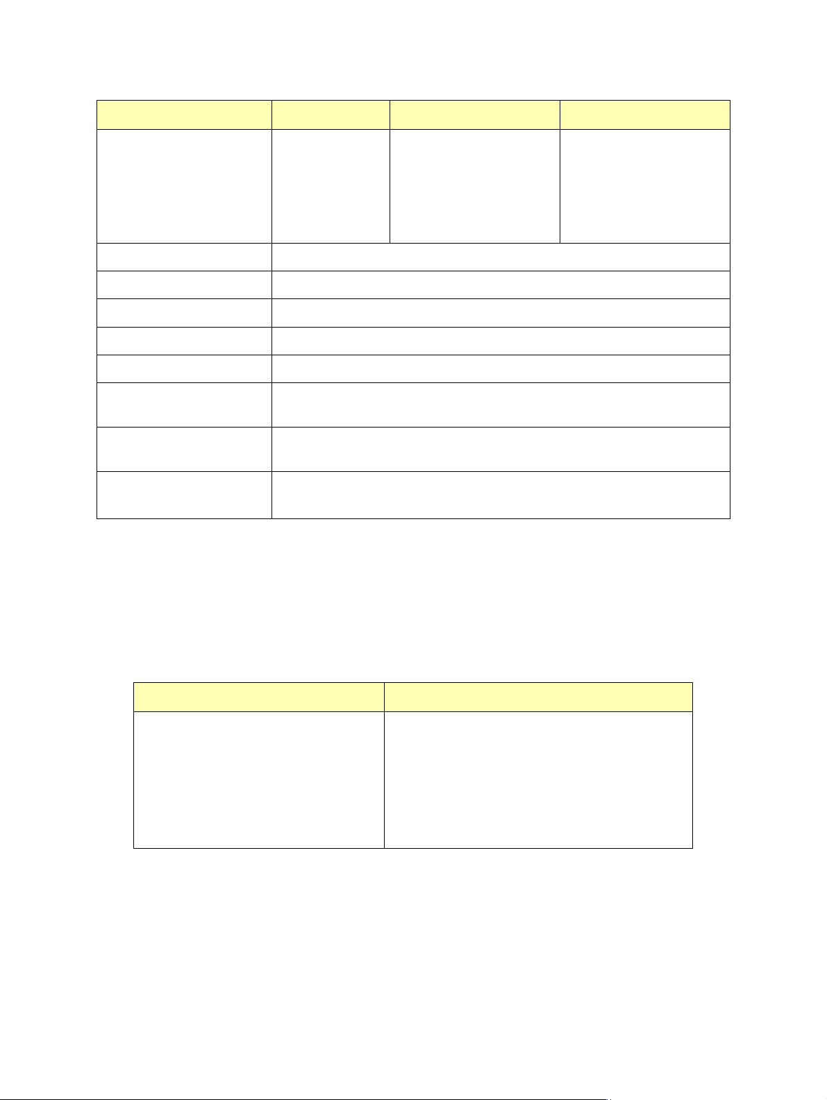
Specification D875 D1525 D2175
Dimensions - Shipping
Height
Width
Depth
Weight
Library
76.5 in (194.3 cm)
49 in (124.5 cm)
37 in (94 cm)
571 lbs (259 kgs)
One expansion bay
72.5 in (184.2 cm)
34 in (86.3 cm)
35 in (89 cm)
185 lbs (84 kgs)
2
(see D875 dimensions)
Operating Temperature 50 to 90F / 10 to 32C
Non - Operating Temperature -40 to 158 F /-40 to 70 C
Operating Humidity 10 to 90% RH (non-condensing)
Operating Voltage 100 to 240 VAC (Auto ranging power supply)
Operating Frequency 50 / 60 Hz
Power Consumption (2
145 W / 495 BTU/hr
Drives)
Power Consumption (12
Drives)
285 W / 972 BTU/hr
If the third power supply is installed, add 37 W / 126 BTU/hr
Options Redundant Power Supplies
Kit for adding two or three SCSI Busses
1
= Actual number of slots and library capacity depends on drive configuration.
3
Two expansion bays
72.5 in (184.2 cm)
34 in (86.3 cm)
35 in (89 cm)
325 lbs (148 kgs)
2
(see D875 dimensions)
2
= Represents the shipping weight of each expansion bay. The expansion bays are shipped on a
separate pallet.
3
= Additional SCSI busses required depending on number of drives.
Table 11. Media Specifications
Specification Limits
Environmental
Operating Temperature
(at 1000 ft or less ASL)
Non-Operating Temperature
Max Gradient Temperature / hr
Operating Humidity
Non-Operating Humidity
+10 to +32
- 40 to +50
10o C (18oF per hour)
10 to 85% RH non-condensing
10 to 95% RH non-condensing
oC
(+50 to +90o F)
oC
(- 40 to +122oF)
Appendix A Plasmon D875 - D2175 User Manual
Page 52 Document Revision E
Page 55
Power Cable Specification
The voltage rating and the current rating of the power cord set shall be higher than the rated voltage
and current of this unit. The voltage rating of the power cord set shall be higher than the power source.
For the U.S. and Canada:
Power cord must be UL listed and CSA labeled. Type SJT, SVT, ST, SJO or SO, 3-conductors, No. 18
AWG, rated 125v, 10A
For Germany and continental Europe:
STROMANFNAHME: 100-240 VAC, 50/60 Hz, 6A.
Für eine 230V-Anwendung, ist eine harmonisierte <HAR> konfektionierte Leitungsschnur, Typ
H05vvf3G1.00, die für 250V/10A oder die Gleichwertigkeit geeognet ist, zu benutzen.
If there are any questions in regards to the proper cord sets, consult the distributor.
SCSI Cable Specification
SCSI Cables and Connectors
Plasmon recommends using Wide LVD SCSI cables and connectors that conform to SCSI-3
specifications.
NOTE
To comply with the regulations and standards in this manual, all
SCSI cables and connectors used with the library must be
properly shielded.
SCSI Cable Length
Plasmon recommends using SCSI cables that conform to SCSI-3 specifications with high density 68pin connectors. The following table shows the allowable cable lengths for the LVD SCSI interface.
Table 12. Maximum Allowable SCSI Cable Length (LVD)
Library Internal Cable Length Allowable External Cable
Length
Bus 1 10 ft (3 M) 29 ft (9 M)
Bus 2 3 ft (1 M) 36 ft (12 M)
Bus 3 3 ft (1 M) 36 ft (12 M)
SCSI Termination
The Plasmon D875 - D2175 libraries are terminated internally. No external termination is required.
Plasmon D875 - D2175 User Manual Appendix A
Document Revision E Page 53
Page 56

Appendix A Plasmon D875 - D2175 User Manual
Page 54 Document Revision E
Page 57
APPENDIX B
SCSI BUS INFORMATION
SCSI Bus Configurations
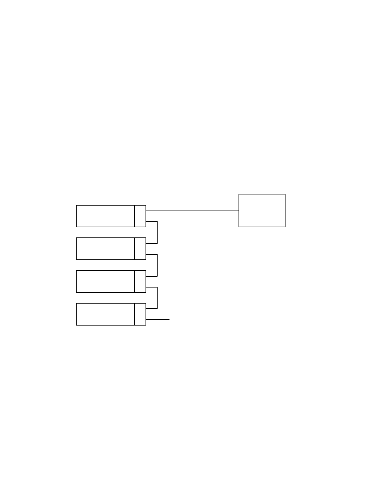
The following three figures show how to connect drives for single, dual and triple SCSI bus
configurations. Each bus in the library supports a maximum of four drives. The library address should
always be assigned to SCSI Bus 1.
Single Bus Configuration
Driv e 1
Driv e 2
Driv e 3
Driv e 4
SCSI Bus 1
Ter minator
Figure 37. Single Bus Configuration
Hos t
Computer
Plasmon D875 - D2175 User Manual Appendix B
Document Revision E Page 55
Page 58
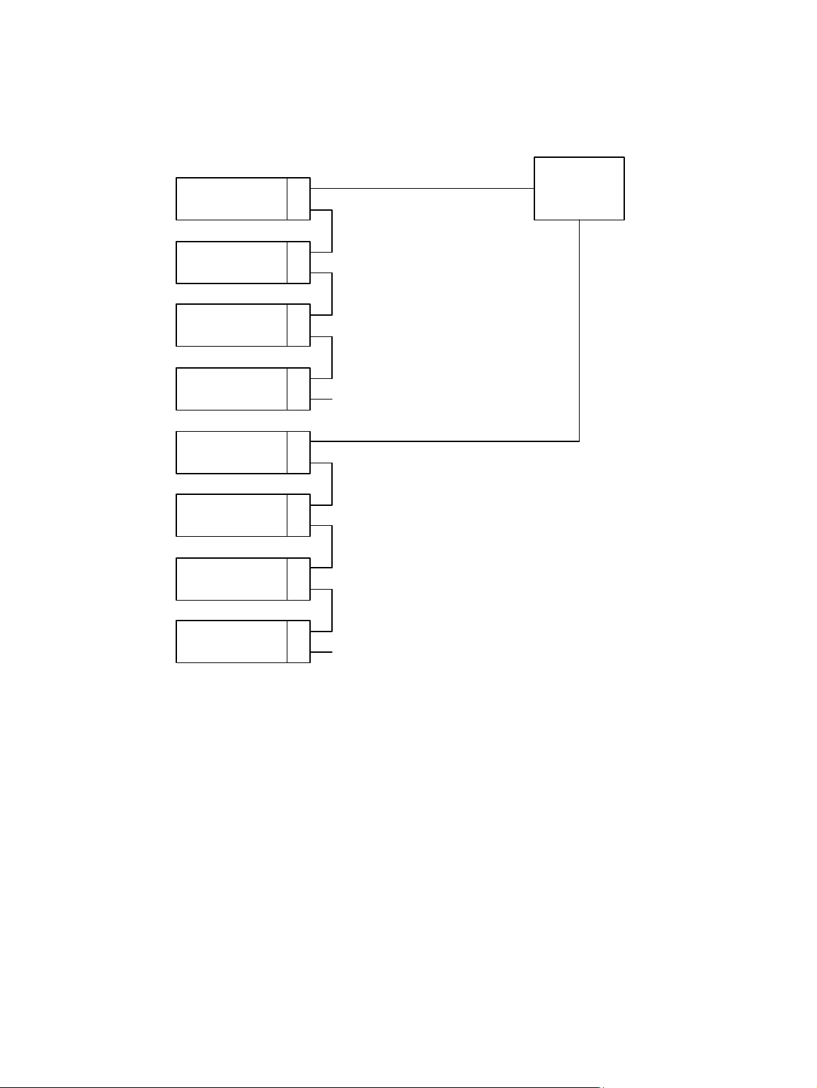
Dual Bus Configuration
Drive 1
Drive 2
Drive 3
Drive 4
Drive 5
Drive 6
Term inator
SCSI Bus 1
SCSI Bus 2
Host
Computer
Drive 7
Drive 8
Term inator
Figure 38. Dual Bus Configuration
Appendix B Plasmon D875 - D2175 User Manual
Page 56 Document Revision E
Page 59
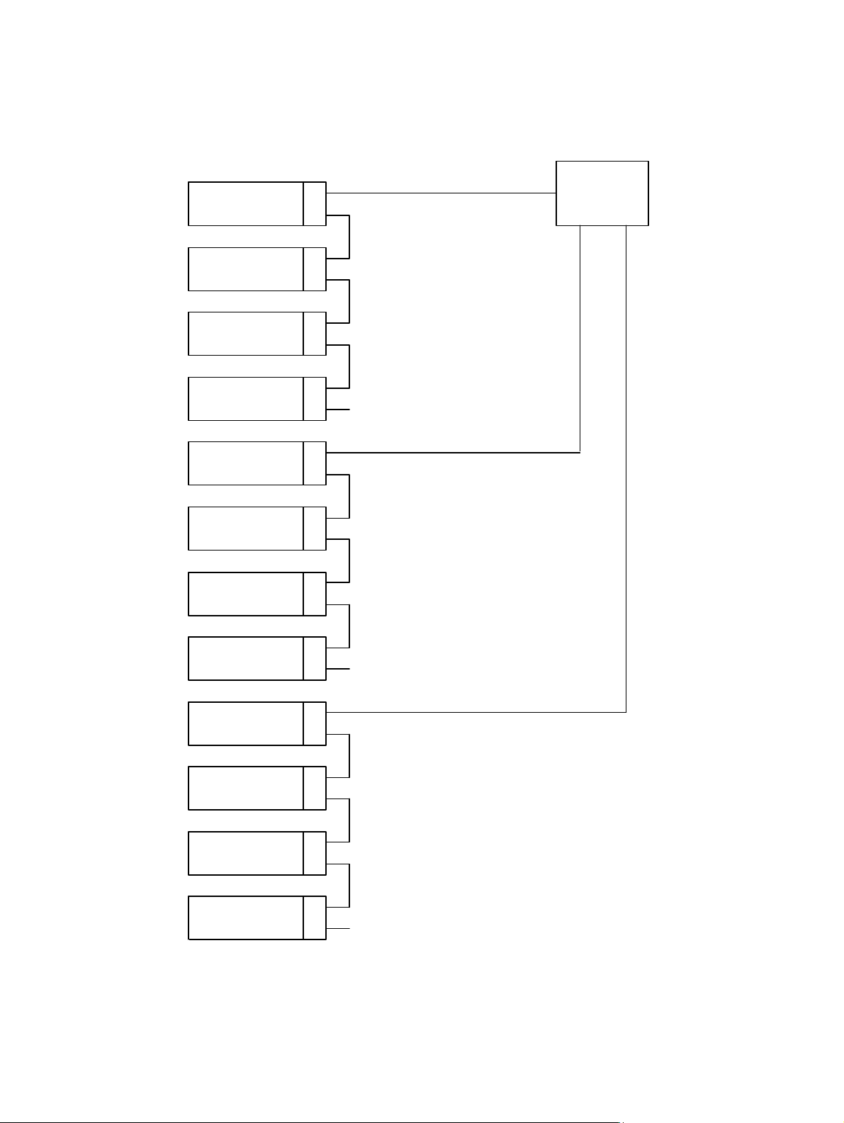
Triple Bus Configuration
Drive 1
Drive 2
Drive 3
Drive 4
Drive 5
Drive 6
Term inator
SCSI Bus 1
SCSI Bus 2
Host
Computer
Drive 7
Drive 8
Drive 9
Drive 10
Drive 11
Drive 12
Term inator
SCSI Bus 3
Term inator
Figure 39. Triple Bus Configuration
Plasmon D875 - D2175 User Manual Appendix B
Document Revision E Page 57
Page 60
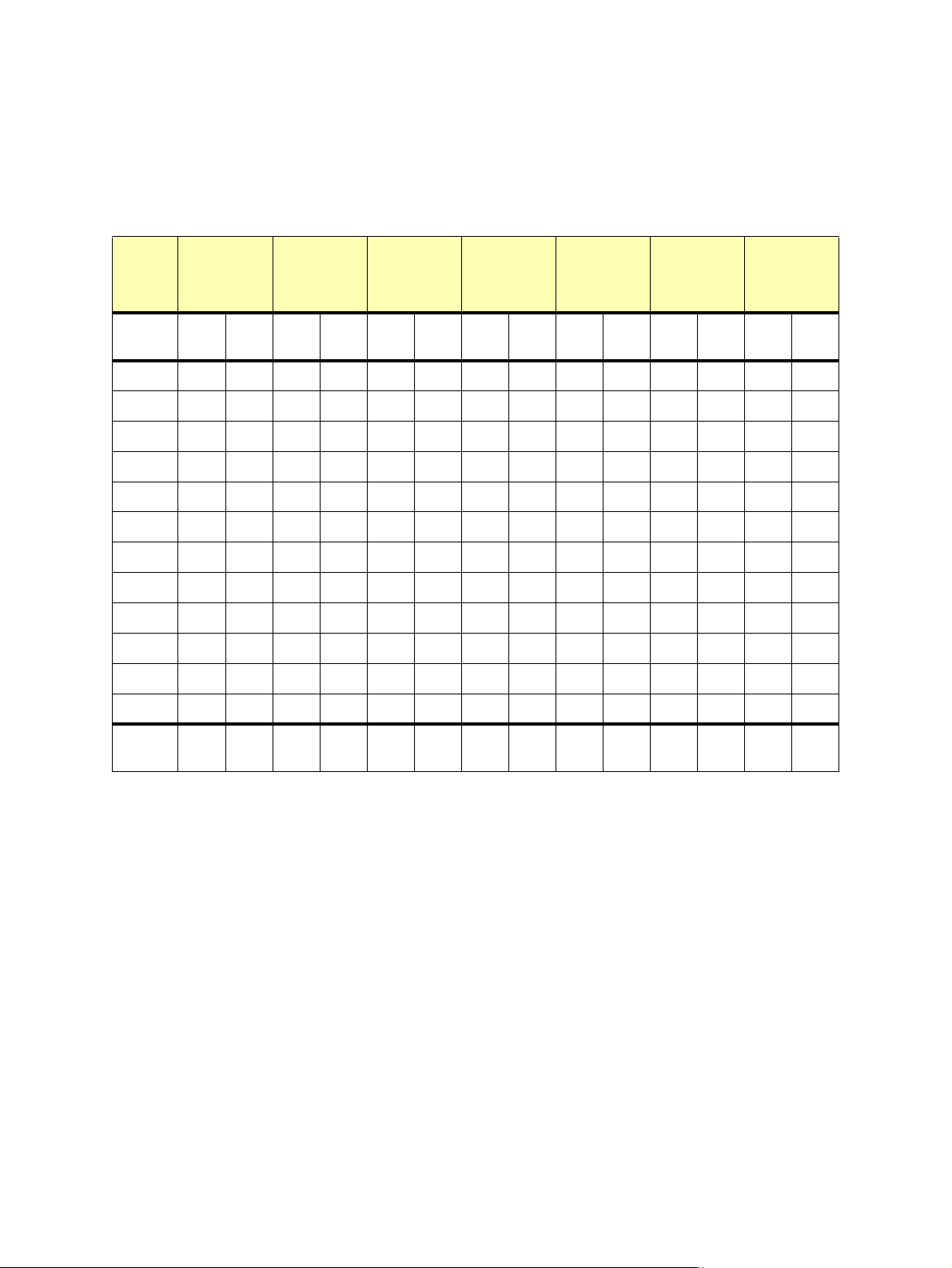
SCSI ID Configuration
The SCSI IDs are set at the factory to the following settings for the Plasmon D875 - D2175 libraries:
Table 13. Factory Default SCSI IDs for the D875 - D2175 Libraries
Device Bus
Config
1
SCSI
SCSIIDSCS
Bus
Drive 110101010101010
Drive 211111111111111
Drive 312201212121212
Drive 413211313131313
Drive 5 2020202020
Drive 6 2121212121
Drive 7 22303022
Drive 8 23313123
Drive 9 3230
Drive 10 3331
Drive 11 32
Drive 12 33
Bus
Config
Bus
2
SCSIIDSCSI
Bus
Config
3
Bus
Config
SCSIIDSCSI
Bus
Bus
4
SCSIIDSCSI
Bus
Config
Bus
5
SCSIIDSCSI
Bus
Config
Bus
6
SCSIIDSCSI
Bus
Config
Bus
7
SCSI
ID
Changer
Device
16161616161616
Appendix B Plasmon D875 - D2175 User Manual
Page 58 Document Revision E
Page 61
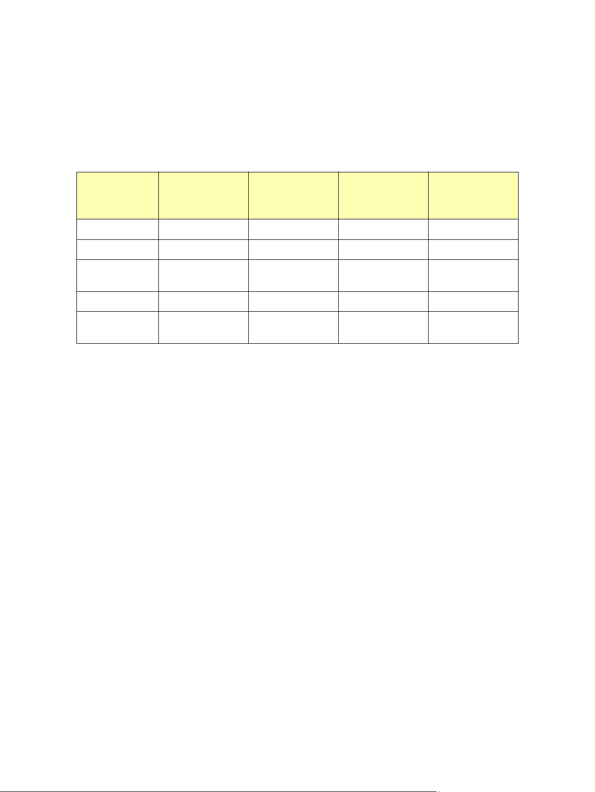
Drive Combinations
The information in the table below shows the maximum drive combinations for three SCSI busses.
Note that DVD-R drives may only be used on Bus 2 and Bus 3.
Table 14. SCSI Bus and Drive Combinations
Drive
Combination
DVR - RAM only 4 4 4 12
DVD - R only 0 2 2 4
DVD - RAM /
DVD - R
Multi Drive 4 4 4 12
Maximum Drives
per Bus
Bus 1
Maximum Num-
ber of Drives
4 (DVD - RAM only) 2 (DVD - R only) 2 (DVD - R only) 8
4 4 4 12 (maximum drives
Bus 2
Maximum Num-
ber of Drives
Bus 3
Maximum Num-
ber of Drives
Maximum Total
Number of
Drives
for the library)
Plasmon D875 - D2175 User Manual Appendix B
Document Revision E Page 59
Page 62

Appendix B Plasmon D875 - D2175 User Manual
Page 60 Document Revision E
Page 63

APPENDIX C
SAFETY AGENCY STANDARD
The D875 - D2175 library is in compliance with the following domestic and international product safety
standards when the unit is properly installed and operated in accordance with the product documents.
Safety IEC 60950 3rd Edition: (1999), UL 60950 3rd Edition: (2000), CSA C22.2 No.60950
Emission EN 55011 Class A, EN 55022 / CISPR 22 Class A, FCC Class A, CNS 13438 Class A,
EN 61000-3-2, EN 61000 3-3
Immunity EN 55024
FCC Notice
This equipment has been tested and found to comply with the limits for a Class A digital device,
pursuant to part 15 of the FCC Rules. These limits are designed to provide reasonable protection
against harmful interference when the equipment is operated in a commercial environment. This
equipment generates, uses, and can radiate radio frequency energy and, if not installed and used in
accordance with this instruction manual, may cause harmful interference to radio communications.
Operation of this equipment in a residential area is likely to cause harmful interference in which case
the user will be required to correct the interference at his own expense.
Shielded cables are required for this device to comply with FCC Rules. Use shielded cables when
connecting this device to others.
Industry Canadian Notice per ICES-003
English: This Class A digital apparatus meets all requirements of the Canadian Interference-Causing
Equipment Regulations.
French: Cet appareil numérique de la classe A respecte toutes les exigences du Règlement sur le
matériel brouilleur du Canada.
Australia / New Zealand
This equipment has been tested and complies with AS/NZS 3548.
Plasmon D875 - D2175 User Manual Appendix C
Document Revision E Page 61
Page 64
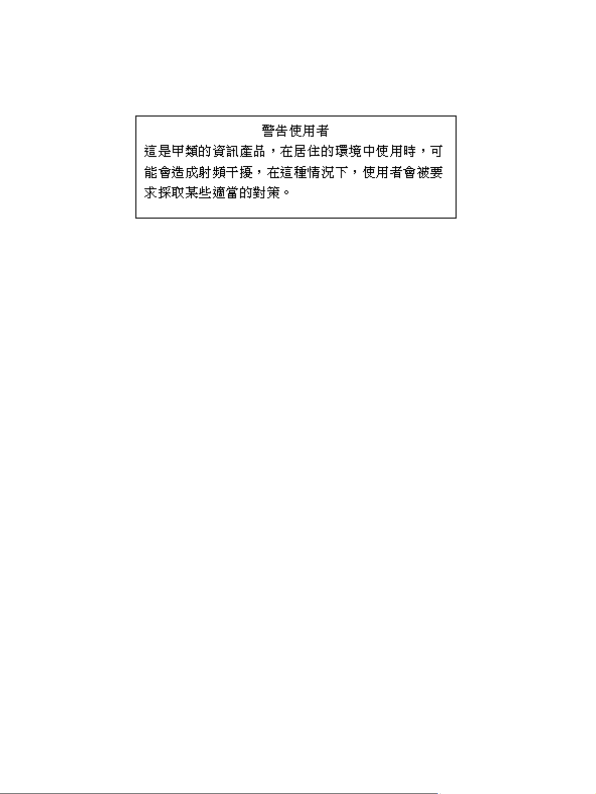
Taiwan (BSMI) Class A Warning Statement
Laser Safety Notice
This library is a Class 1 Laser Product.
CDRH Regulations
The Center for Devices and Radiological Health (CDRH) of the U.S. Food and Drug Administration
implemented regulations for laser products on August 2, 1976. These regulations apply to laser
products manufactured from August 1, 1976. Compliance is mandatory for products marketed in the
United States.
Lithium Battery
The Main Control Board and the Front Control Panel contain a lithium battery which could explode if
incorrectly replaced. Replace only with a qualified replacement battery. Return the old battery to the
manufacturer for disposal or dispose of in accordance with local regulations for the disposal of lithium
batteries.
“ATTENTION: IL Y A DANGER D’EXPLOSION S’IL Y A REPLACEMENT INCORRECT DE LA
BATTERIE. REMPLACER UNIQUEMENT AVEC UNE BATTERIE DU MEME TYPE OU D’UN TYPE
RECOMMANDE PAR LE CONSTRUCTEUR. METTRE AU REBUT LES BATTERIES USAGEES
CONFORMEMENT AUX INSTRUCTIIONS DU FABRICANT.”
Vorsicht! Explosionsgeahr bei unsachgemabem Austausch der batterie. Ersatz nur durch denselbel
oder einen vom Hersteller empfolhenen gleichwertigen Typ. Entsorgung gebrauchter Batterien nach
Angaben des Herstellers.
Appendix C Plasmon D875 - D2175 User Manual
Page 62 Document Revision E
Page 65
APPENDIX D
ERROR CODES
If an error occurs while on-line, the library retries the operation that failed. If the retried operation fails,
the library attempts to return the media to its location before the operation and sends an error code to
the host computer. This error code is displayed on the front panel display of the library.
The following error codes are provided to assist in detecting and finding the corrective action for a
library error. Note the error code number displayed on the front panel display, and find the
corresponding error code in the following table. The table is sorted by error code number.
CAUTION
The corrective actions shown in the error code table should only
be performed by qualified Plasmon trained personnel.
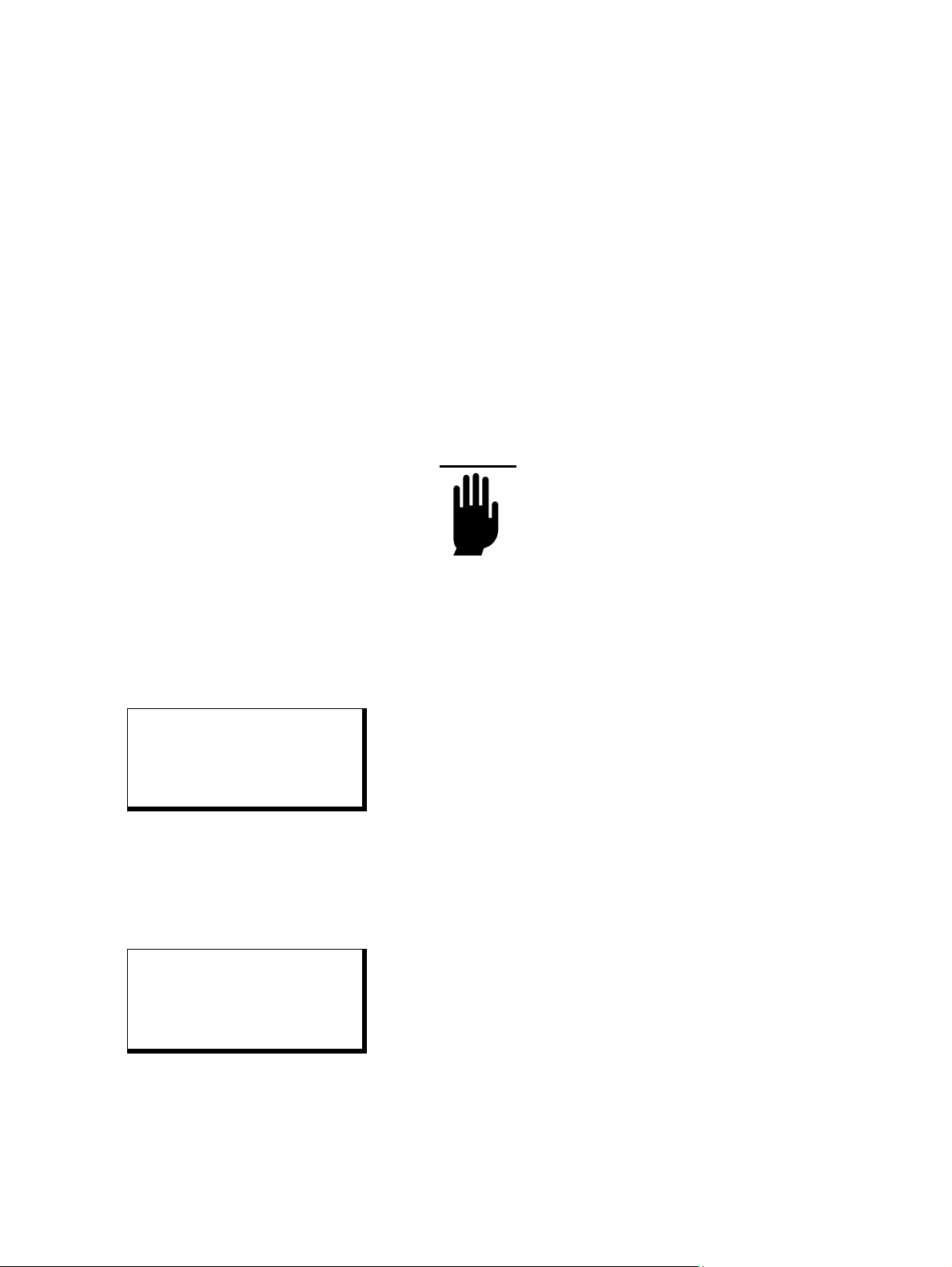
Example:
When a library error occurs, the LCD screen displays the error temporarily as shown below
ERROR 03
NVRAM FAIL
SUBCODE: 01
ODSELECTP
After a few seconds the display changes as shown below:
D:CCCCCCTT:C
MAG:.....I:. E03
ODSELECTP
[C]
[?]
OGP
Press [C] to clear the error
OGP
Press [?] to re-display the error
Plasmon D875 - D2175 User Manual Appendix D
Document Revision E Page 63
Page 66
Table 15. D875 - D2175 Error Codes
Error
Code
Subcode
Error
Description
Subcode
Description
Compo-
nent
Corrective Action
(hex)
00 0 Unknown error No additional info No additional info
02 1 Flash checksum Found during SCSI
send diagnostics
2 Found during period
check
03 1 NVRAM fail Failure in startup Main control-
ler circuit
board
0A 1 Bad element
code
0C 1 OP stack over-
flow
2 Undoing operation
0D 1 Bad OP stack
index
Recording operation Firmware Download new firmware
Nothing to undo Firmware Download new firmware
Firmware Download new firmware
Replace Main controller, or
flash FW download performed
Replace Main controller
2 Invalid undo operation
0E group # Flash program
fail (main code)
0F group # Flash program
fail (DSP)
11 1 DSP not
responding
2 No response for picker
3 No response for pivot
4 No response SSC of
code
Code down load
progress (MAIN code)
Code download
progress (DSP code)
No response for lift
motor movement command
motor movement command
motor movement command
DSP
Main controller or Firmware
Main controller or Firmware
Main controller or Firmware
Replace Main controller
download new firmware
Replace Main controller
download new firmware
Replace Main controller
download new firmware
Appendix D Plasmon D875 - D2175 User Manual
Page 64 Document Revision E
Page 67
Error
Code
(hex)
Subcode
5 No communication
Error
Description
Subcode
Description
response from DSP for
a command sent
Compo-
nent
Corrective Action
12 1 Cable connect
fail
2 Bad cable, VP decoder
3 Main circuit board cable
4 Main circuit board cable
5 Main circuit board cable
6 Main circuit board cable
7 Drive interface CJ5 to
Bad CJ5 cable, main
controller to VP
decoder circuit board
CJ2 to upper sensors
fail, CJ4 (To Pivot, Lift
circuit board)
fail, CJ5 (to VP decoder
circuit board)
fail, CJ7 (interlock, reference sensor)
fail, CJ10 (To PWR dist
circuit board - supply
monitor)
SCSI converter
8 Drive interface CJ11 to
SCSI converter
9 Magazine interface CJ4
to magazine detector
circuit board
10 Magazine interface CJ7
to Access door solenoid
& sensor
11 Magazine interface CJ8
to flipper
12 Drive interface circuit
board, bad address
plug CJ8
13 Magazine interface cir-
cuit board, bad address
plug CJ3
Plasmon D875 - D2175 User Manual Appendix D
Document Revision E Page 65
Page 68
Error
Code
Subcode
Error
Description
Subcode
Description
(hex)
13 1 Fuse overload Main controller fuse 1
overload +24V interface
CJ3 to CAN bus
2 Main controller fuse 2
overload +5v interface
CJ3 to CAN bus
3 Main controller fuse 3
overload +24V interface
CJ4 to pivot, lift, MTE
4 Main controller fuse 4
overload +5V interface
CJ4 to pivot, lift, MTE
5 Main controller fuse 5
overload +5V interface
CJ5 to VP decoder
6 Main controller fuse 6
overload +5V interface
CJ8 to MC SCSI
adapter
Compo-
nent
Corrective Action
7 Main controller fuse 7
overload +12V interface
CJ8 to MC SCSI
adapter
8 Main controller fuse 9
overload +5V interface
CJ12 to External SCSI
interface circuit board
9 Main controller fuse 10
overload +24V for lift
motor, & interface CJ4
to pivot & lift circuit
board's
10 Main controller fuse 11
overload +24V for stepper motors, & interface
CJ4 to pivot, lift, MTE
11 Drive interface 3V regu-
lator overload (U14)
12 Drive interface 12V
fuse overload (F2)
Appendix D Plasmon D875 - D2175 User Manual
Page 66 Document Revision E
Page 69
Error
Code
(hex)
Subcode
13 Drive interface 24V
14 SCSI Converter SE
15 SCSI Converter SE
16 SCSI Converter LVD
17 SCSI Converter LVD
18 Magazine interface
Error
Description
Subcode
Description
fuse overload (F3)
term pwr fuse overload
(F1) to drive modules
term pwr fuse overload
(F1) to drive modules
term pwr fuse overload
(F2) to bus 1 or bus 3
term pwr fuse overload
(F2) to bus 2
3.3V regulator overload (U4)
Compo-
nent
Corrective Action
19 Magazine interface
access door solenoid
24V fuse overload (F2)
20 Magazine interface flip-
per 24V fuse overload
(F3)
21 Power distribution fuse
1 overload +5V interface CJ7 for Power to
Mag. circuit board
22 Power distribution fuse
2 overload +5V interface CJ7 for Power to
RMI circuit board
23 Power distribution fuse
3 overload +24V interface CJ7 for Power to
Mag. circuit board
24 Power distribution fuse
4 overload +24V interface CJ7 for Cabinet
cooling fans
14 1 Circuit board fail Comm error with VP
decoder circuit board
Plasmon D875 - D2175 User Manual Appendix D
Document Revision E Page 67
Page 70
Error
Code
(hex)
Subcode
2 VP Decoder circuit
3 More than one column
4 VP Emitter / detector
5 VP Emitter / Detector
6 VP Emitter / Detector
7 Unblocked response
8 Drive interface I/O loop-
Error
Description
Subcode
Description
board control failure
blocked on VP decoder
circuit board
failure
circuit board margin
test fail
circuit board blocked
response test fail
test fail (VP Emitter /
Detector circuit board)
back test failed
Compo-
nent
Corrective Action
9 Drive interface 3.3V
failure
10 Drive interface 2V fail-
ure
11 Drive interface 24V fail-
ure
12 SCSI Converter SE
term power bad bus 1
or bus 3
13 SCSI Converter LVD
term power bad bus 1
or bus 3
14 SCSI Converter SE
term power bad bus 2
15 SCSI Converter LVD
term power bad bus 2
16 Mag interface not
present
17 Main controller crystal
failure
Appendix D Plasmon D875 - D2175 User Manual
Page 68 Document Revision E
Page 71
Error
Code
(hex)
Subcode
Error
Description
Subcode
Description
Compo-
nent
Corrective Action
15 1 Can time out -
drive
2 CAN time out getting
3 CAN time out getting
4 CAN time out getting
5 CAN time out setting
6 CAN time out setting
7 CAN time out setting
8 CAN time out powering
9 CAN time out getting
CAN time out checking
drive interface
drive status
SCSI converter status
fan tach values
drive loaded
drive unloaded
drive id
on drive
drive type
Drive interface circuit
board, CAN
cables
Replace drive interface circuit
board or CAN cables
10 CAN time out powering
off drive
11 CAN time out clamping
drive
12 CAN time out unclamp-
ing drive
13 CAN time out complet-
ing clamp/unclamp
drive
14 CAN time out isolating
bus
15 CAN time out restoring
bus
16 CAN time out blinking
LED for drive status
17 CAN time out turning
off LED for drive status
Plasmon D875 - D2175 User Manual Appendix D
Document Revision E Page 69
Page 72
Error
Code
(hex)
Subcode
Error
Description
Subcode
Description
Compo-
nent
Corrective Action
16 1 Can time out -
mag board
2 CAN time out reading
3 CAN time out writing
4 CAN time out checking
5 CAN time out read mag
6 CAN time out reading
7 CAN time out turning
8 CAN time out turning
CAN time out sending
command to flipper
flipper EEPROM
flipper EEPROM
mag interface circuit
board
sensors
mag interface circuit
board temp
on mag LED
off mag LED
Magazine
interface circuit board,
CAN cables
Replace magazine interface
circuit board or CAN G103
cables
9 CAN time out blinking
10 CAN time out firing mag
11 CAN time out start ver-
12 CAN time out reset
17 1 Main board
SCSI termpower
18 1 Power supply
voltage
2 12V out of range during
mag LED
door solenoid
ify temp
mag door state
No term pwr at MC
SCSI adapter circuit
board
5V out of range during
check main circuit
board cable check
check main circuit
board cable check
Bad power
supply
Replace power supply
Appendix D Plasmon D875 - D2175 User Manual
Page 70 Document Revision E
Page 73
Error
Code
(hex)
Subcode
3 24V out of range during
Error
Description
Subcode
Description
check main circuit
board cable check
Compo-
nent
Corrective Action
19 1 Power supply fail One of the power sup-
ply has been removed
2 Power supply fan has
failed
3 Power supply power
failure
1A 1 SCSI bus isola-
tion
2 Time out waiting for iso-
1B 1 Too few power
supplies
22 1 Bus already iso-
lated
2 Restore drives, isolate
Time out waiting for isolate bus command to
complete
late bus to complete
while restoring bus
More than one drive
interface board and
only one power supply
Service drives, isolate
request and bus
already isolated
request and bus
already isolated
Power supply, or supply
cable
Replace power supply, check
supply cable
Add power supply
23 1 Bus not isolated Service drives, un-iso-
late request and bus
not isolated
2 Restore drives, un-iso-
late request and bus
not isolated
31 1 Drive not
installed
3 Checking a move from
4 Checking a move to a
Plasmon D875 - D2175 User Manual Appendix D
Document Revision E Page 71
Positioning to drive Drive inter-
face cables
a drive
drive
Replace cables or drive interface circuit board or configure
in drive
Page 74
Error
Code
(hex)
Subcode
5 Checking a SCSI posi-
Error
Description
Subcode
Description
tion to drive command
Compo-
nent
Corrective Action
32 1 Drive not con-
nected
2 Drive not connected
33 1 Drive clamp fail Drive clamp fail while
34 1 Drive unclamp
fail
35 1 Drive load fail Tray not seen in picker
2 VP or Tray sensor
3 Drive not set to loaded
4 Drive load retry aborted
36 1 Drive unload fail Drive not unclamped Drive, drive
Drive not connected
that was previously
installed
when restoring drives
loading drive
Drive unclamp fail
unloading drive retry
while picker moving to
load position
blocked after retracting
picker to fwd position
Drive interface cables
Drive, drive
cables
Drive, drive
cables
MTE sensor Replace MTE
MTE sensor,
VP sensor
cables
Replace or reconnect drive
cables
Replace drive or cabling
Replace drive or cabling
Replace MTE, VP sensor, run
offsets to correct positioning
Replace drives or cables
2 Pick finger did not hold
on to tray, VP or Tray
sensor blocked
3 No tray seen in unload
attempt
4 Picker Tray sensor
blocked during tray only
check of drive unload
5 Picker Tray sensor
unblocked during tray
only check of drive
unload
37 1 Drive is clamped Drive is clamped, can't
unclamp (checking
move from a drive)
Appendix D Plasmon D875 - D2175 User Manual
Page 72 Document Revision E
Alignment
problem
Alignment
problem,
MTE tray
sensor
Alignment
problem,
MTE tray
sensor
Alignment
problem,
MTE tray
sensor
Drive, drive
cables
Run offsets
Run offsets, replace MTE
Run offsets, replace MTE
Run offsets, replace MTE
Replace Drive, drive cables
Page 75
Error
Code
(hex)
Subcode
Error
Description
Subcode
Description
Compo-
nent
Corrective Action
2 Drive is clamped, can
38 1 Drive in service
state
2 In service state,
3 In service state,
39 1 Drive not in ser-
vice state
3F 1 Drive Addr con-
flict
2 Address conflict with
40 1 Not supported
by bus config.
not unclamp (checking
move to a drive)
In service state,
attempting to turn drive
off in maint menu
attempting to turn drive
on in maint menu
attempting to put drive
in service state via
SCSI command
Restoring drives, not in
a service state
Address conflict with
changer
another drive
Attempt to put drive in
service state via SCSI,
drive not supported by
current bus config.
Drive, drive
cables
Replace Drive, drive cables
Follow operating instructions
Follow operating instructions
Correct address in setup configuration
2 Attempt to restore drive
via SCSI, drive not supported by current bus
config.
41 1 Drives overheat-
ing
42 1 Drives shut-
down - heat
43 1 Low fan speed-
drive
44 1 Drive shutdown-
fan
Plasmon D875 - D2175 User Manual Appendix D
Document Revision E Page 73
Warning for an over
heating drive
Drive will be shutdown
due to overtemp condition, alert host of 90 sec
delay before shutdown
Warning for low fan
speed in a drive module
Drive will be shutdown
due to fan failure, alert
host of 90 sec delay
before shutdown
Cabinet
Te mp
Cabinet
Te mp
Fan Replace fan
Fan Replace fan
Check room temp
Check room temp
Page 76
Error
Code
(hex)
Subcode
Error
Description
Subcode
Description
Compo-
nent
Corrective Action
51 1 Picker pos fail Picker position was ter-
minated on home from
store attempt
2 Picker did not reach
position intended
3 Lift motor not previously
homed before picker
position attempt
4 Unknown picker posi-
tion destination state
5 Picker failed to reach
home as its destination
6 Picker stalled while
picking tray, lost steps
going to home position
7 Picker stalled while
moving out to store a
media tray. This problem is detected when
the picker returns to the
home position
Alignment
problems
Run offsets, replace tray
8 Picker home sensor not
blocked after picking a
tray.
9 Edge of picker not seen
by Tray sensor while
positioning to home
10 Pick home sensor
blocked, positioning to
destination other than
home
52 1 Swap pickers fail Could not change the
active picker (selector
nut pawl or spring may
be damaged)
54 1 Picker misposi-
tion
Picker finger is in a
danger zone for moving
the lift
Obstruction
or alignment
MTE Replace MTE
Alignment
problems,
MTE
Clear obstruction, run offsets
Run offsets or replace MTE
Appendix D Plasmon D875 - D2175 User Manual
Page 74 Document Revision E
Page 77
Error
Code
(hex)
Subcode
2 Lift motor not homed or
3 Picker edge is blocking
Error
Description
Subcode
Description
invalid lift position,
Picker edge is blocking
the Tray sensor
the Tray sensor during
a position attempt
Compo-
nent
Corrective Action
55 1 Picker not at
drive
2 Picker not positioned in
57 1 Pick tray fail VP or Tray sensor
2 Picker Tray sensor
3 Picker Tray sensor not
4 Terminated SCSI task
Picker not positioned in
front of drive during
load drive attempt
front of drive during
unload drive attempt
blocked by tray, picker
finger disengaged from
tray after starting to
pick media
blocked on tray only
check after picking tray
blocked on tray only
check after picking tray
or completion status not
started during a pick
tray retry
Alignment
problem
Position to drive
Run offsets. Replace tray
58 1 Store tray fail Tray front or back did
not block Tray sensor
during a store
2 Both sensors in the flip-
per not made after
store to flipper
3 Picker finger did not
release from the tray
after store attempt, VP
or Pemt blocked
Plasmon D875 - D2175 User Manual Appendix D
Document Revision E Page 75
Alignment or
obstruction
Alignment,
flipper sensors
Alignment
Run offsets, replace tray
Page 78
Error
Code
(hex)
Subcode
4 Terminated SCSI task
Error
Description
Subcode
Description
or completion status not
started during a store
tray retry
Compo-
nent
Corrective Action
61 1 Lift Position fail Destination encoder
count out of boundaries
2 Position lift destination
not reached (time-out)
3 Destination lift position
is invalid
4 Position retry aborted
63 1 Lift blocked VP sensor blocked, last
col Blocked is set
2 Lift is not in column of a
blocked VP sensor during initialization
3 VP or Tray sensor
blocked after storing
media, during initialization.
4 Blocked VP sensor not
in the column clear
attempt being tried
Bad Lift
motor/
encoder
Tray out of
slot, Bad Vp
Bad Vp sensor, tray out
slot
Obstruction
in slot
Replace lift motor
Reseat tray in slot, replace
VP
5 VP or Tray sensor
blocked after store or
load, during clear
attempt.
6 VP or Tray sensor
blocked after store
operation (move from
lift)
7 VP or Tray sensor
blocked trying to return
a tray to its last known
location.
69 1 Pivot align fail Too much gear back-
lash / gear is loose during home pivot attempt
Appendix D Plasmon D875 - D2175 User Manual
Page 76 Document Revision E
Obstruction
in slot or
drive
Obstruction
in slot
Obstruction
in slot, alignment
Pivot motor
mounting
Realign or replace pivot
motor
Page 79
Error
Code
(hex)
Subcode
Error
Description
Subcode
Description
Compo-
nent
Corrective Action
6A 1 Pivot Fail Pivot is loosing posi-
tion accuracy, not on
alignment flag verifying
pivot position
2 Outside allowed pivot
soft deviation steps, but
position will succeed
3 Outside allowed pivot
soft deviation steps, but
position will succeed
4 Outside allowed pivot
hard deviation steps,
position will fail
5 Destination pivot value
out of range
6 Pivot position failed to
be reached (time out)
70 1 Mag door open
fail
Time out waiting for
mag door status
Offsets Run offsets
Mag interface circuit
board, mag
solenoid
Replace Mag circuit board or
solenoid, check mechanical
obstruction
71 1 Mag access
door is open
2 Mag door opened in
72 1 Door open pre-
vented
74 1 Rear door is
open
2 Background check of
3 Rear door open during
Mag door open during
initialization
online mode (not by
solenoid)
SCSI prevent command was issued by
host, mag door opening
is not allowed
Background check of
rear door open during
initialization
rear door open during
online operation
online test ready check
Close door
Issue SCSI allow from host
Close Rear door
Plasmon D875 - D2175 User Manual Appendix D
Document Revision E Page 77
Page 80
Error
Code
(hex)
Subcode
Error
Description
Subcode
Description
Compo-
nent
Corrective Action
80 1 Element not
present
2 Checking move to an
3 SCSI position attempt
81 1 Magazine not
present
2 Magazine not present
84 1 Source is empty Online check of
2 Online check of
Checking move from an
invalid fixed slot location
invalid fixed slot location
to an invalid slot location
Magazine not present
during verification of
installation
during recovery
NVRAM says source
element is empty
NVRAM says source
element is empty, to
element is full (not
exchange command)
Correct host software
Replace magazine
Run Check Elements, Host
needs to check inventory
3 Src element = 1st desti-
nation element during
exchange command
85 1 Destination is full Online check of
NVRAM says destination element is full (not
an exchange command)
2 Online check of
NVRAM says destination element is full
(picker address not
zero)
3 1st destination element
= 2nd destination element during exchange
command
Appendix D Plasmon D875 - D2175 User Manual
Page 78 Document Revision E
Run Check Elements, Host
needs to check inventory
Page 81
Error
Code
(hex)
Subcode
4 Picker is 2nd destina-
Error
Description
Subcode
Description
tion element, src element = 2nd dest
element
Compo-
nent
Corrective Action
86 1 Element unexp
empty
2 Tray not seen during
87 1 Element unexp
full
2 Picker is full, attempting
8B 1 Picker is full VP or Pemt sensor
2 VP or Pemt sensor
3 Both pickers are not
No trays to use in cycle
Full test
pick attempt
Home sensor blocked
after store attempt
to return tray to last element
blocked by tray moving
to the pick position
blocked moving to the
unload drive position.
empty to do an
exchange (during
check move)
Obstruction
in path, Alignment problem
Firmware,
Picker faulty
Run Check Elements
Check path, run offsets
Tray in picker while picking,
initialize and retry, replace
picker
4 Picker full, not a move
to Lift and from Lift (during check move)
5 SCSI exchange 2nd
destination picker,
source not picker
8C 1 Both pickers full Check move, NVRAM
says both pickers full
2 Check single element,
NVRAM says both pickers full
3 SCSI Mag door open,
both pickers full so
magazine can't be
checked
Plasmon D875 - D2175 User Manual Appendix D
Document Revision E Page 79
Main controller circuit
board, firmware
Firmware recovery issue,
replace Main controller circuit board
Page 82
Error
Code
(hex)
Subcode
Error
Description
Subcode
Description
Compo-
nent
Corrective Action
8D 1 No media to flip-
per
2 No media in source ele-
3 No media in destina-
90 1 Tray in drive Tray in a drive while
9C 1 Tray magazine
unknown
9D 1 Element scan
fail
2 Invalid Element (current
No media in tray to flipper for move medium
command
ment to flipper for
exchange medium
command
tion element to flipper
for exchange medium
command
attempting to park
Source magazine for
tray unknown when
returning trays to there
last known elements
Failed to position lift or
picker properly while
checking elements.
element check)
Need media Provide media for use
Drive Drive has tray, either in ser-
vice mode, or bad drive
Recovery
Alignment
problem
Run offsets
B2 1 Flipper invalid
position
B3 1 FS EEPROM
write fail
B4 1 Missing flipper
tray
B5 1 Flipper is full Both slots of flipper
B6 1 Flipper comm
error
2 Time out for flipper read
3 Time out for flipper read
Appendix D Plasmon D875 - D2175 User Manual
Page 80 Document Revision E
Both flipper home sensors blocked
Write flipper EEPROM
status failed
No tray in flipper
(at least one required)
have trays
Time out for flipper status command
version command
sensors command
Flipper Replace flipper
Flipper, mag
interface circuit board
Flipper, mag
interface circuit board
Replace flipper or mag interface
Replace tray
Remove tray
Replace flipper or mag interface
Page 83
Error
Code
(hex)
Subcode
4 Time out for flipper
5 Time out for flipper
6 Time out for flipper step
7 Time out for flipper step
8 Time out for flip to CCW
9 Time out for flip to CW
10 Time out for fliptest
11 Time out for flipper read
Error
Description
Subcode
Description
home CCW command
home CW command
CW command
CW command
command
command
command
EEPROM command
Compo-
nent
Corrective Action
12 Time out for flipper
13 Time out for flipper
14 Time out for flipper lock
21 Command resent to
22 Comm error on status
23 No ACK from flipper,
B7 21 Flipper power
reset
22 Flipper to mag inter-
write EEPROM command
unlock EEPROM command
EEPROM command
flipper 3 times, flipper
NAK'd
command to flipper
command resent 3
times
Flipper to mag interface
comm err, SNAK bit for
power-up bitmask
face, comm err, SNAK
bit for brown-out bitmask
Flipper Replace flipper
Plasmon D875 - D2175 User Manual Appendix D
Document Revision E Page 81
Page 84
Error
Code
(hex)
Subcode
23 Flipper to mag inter-
Error
Description
Subcode
Description
face, comm err, SNAK
bit for watchdog bitmask
Compo-
nent
Corrective Action
B8 1 Old flipper proto-
col
BA 1, 2, 3 Flipper not hori-
zontal
BB 1 FS EEPROM
lock fail
BC 1 FS EEPROM
unlock
BD 1 FS EEPROM
read fail
2 Status of reading flipper
BE 1 Flipper status fail Status of reading flipper
BF 1 Flipper time out Flipper failed to com-
Old version of firmware
in flipper
Neither of the flipper
home sensors are
blocked
Status of locking flipper
EEPROM failed
Status of unlocking flipper EEPROM failed
Error sending flipper
read EEPROM command
EEPROM failed
read status command
failed
plete command in allotted time
Flipper Replace flipper
Flipper Replace flipper
Flipper, mag
interface circuit board
Flipper, mag
interface circuit board
Flipper, mag
interface circuit board
Flipper, mag
interface circuit board
Flipper Replace flipper
Replace flipper or mag interface circuit board
Replace flipper or mag interface circuit board
Replace flipper or mag interface circuit board
Replace flipper or mag interface circuit board
C1 1 Pick offset fail-
ure
2 Pick offset too many
C2 1 Lift offset failure Lift offset too many
Appendix D Plasmon D875 - D2175 User Manual
Page 82 Document Revision E
Pick offset too many
counts less than nominal
counts greater than
nominal
counts less than nominal
Picker Belt,
Hard stop in
chassis, bad
picker, pick
home sensor
Lift home flag
damaged, lift
home sensor, lift motor
encoder
Verify pick home sensors
working, mech bind in picker
travel, replace MTE
Verify lift flag Ok, lift home
sensor working, mech
obstruction, lift motor encoder
working
Page 85
Error
Code
(hex)
Subcode
2 Lift offset too many
3 Lift offset less than neg-
4 Lift offset greater than
Error
Description
Subcode
Description
counts greater than
nominal
ative physical boundary count
positive physical
boundary count
Compo-
nent
Corrective Action
C3 1 Pivot offset fail-
ure
2 Pivot offset too many
3 Pivot offset less than
4 Pivot offset greater than
C4 1 Offset target fail-
ure
2 Target horizontal posi-
3 Target vertical position
Pivot offset too many
counts less than nominal
counts greater than
nominal
negative physical
boundary count
positive physical
boundary count
Target could not be
found
tion found crudely, but
not with fine resolution
found crudely, but not
with fine resolution
Pivot flags,
pivot circuit
board, pivot
cable, pivot
gear mesh
Offset target,
offset sensor
on MTE
Verify pivot flags OK, pivot
sensors working, pivot gear
mesh is not too tight
Verify offset targets not damaged, Offset sensor is working or replace MTE
4 Reference target not
found
C5 1 Offset ref failure Reference could not be
found
2 Reference vertical posi-
tion found crudely, but
not with fine resolution
Plasmon D875 - D2175 User Manual Appendix D
Document Revision E Page 83
Offset reference sensor
Verify reference sensor working, Replace MTE or detector in chassis
Page 86
Error
Code
(hex)
Subcode
3 Reference horizontal
Error
Description
Subcode
Description
position found crudely,
but not with fine resolution
Compo-
nent
Corrective Action
F7 1 SCSI parity error SCSI parity error Terminator or
SCSI cable
F9 1 Abort mesg
received
FD 1 Host commun
time out
SCSI abort mesg
received
SCSI host communications time out
Terminator or
SCSI cable
Terminator or
SCSI cable
Check conflicting SCSI id's
Check conflicting SCSI id's
Check conflicting SCSI id's
Appendix D Plasmon D875 - D2175 User Manual
Page 84 Document Revision E
Page 87

INDEX
A
access door
..................................................................14
front
magazine ..........................................................14
rear ...................................................................16
agency standards, safety
.........................................61
B
bay installation .........................................................24
bay packing instructions
bulk loading media ...................................................21
..........................................32
C
command processing ..............................................11
components, hardware ............................................14
D
description line .........................................................39
display, front panel ............................................14, 39
door
front access
magazine access ..............................................14
rear access .......................................................16
drive combinations
drive modules
drives, number of ...............................................11, 51
......................................................14
...................................................59
..........................................................15
E
error codes ..............................................................63
expansion bay installation
expansion bay packing instructions
.......................................24
.........................32
G
general information ..................................................11
getting started ..........................................................17
H
hardware components .............................................14
I
I/E port loading ........................................................21
import export port
initializing library ......................................................19
installation
....................................................................24
bay
library ................................................................17
....................................................15
L
LCD symbols, front panel display ............................40
LEDs, magazine slot ................................................22
library
dimensions
environment ......................................................18
initialization .......................................................19
installation
models
packing instructions ..........................................28
position
specifications
unpacking .........................................................17
library status menu
lift assembly
.......................................................51
........................................................17
..............................................................11
.............................................................17
....................................................51
..................................................44
.............................................................16
F
front access door .....................................................14
front panel display
Plasmon D875 - D2175 User Manual Index
Document Revision E Page 85
.............................................14, 39
Page 88

M
magazine .................................................................12
access door
eject button .......................................................21
handling ............................................................13
LEDs
slots
............................................................14, 21
main menu
map
storage slot .................................................16, 23
media
handling
loading ........................................................11, 21
movement
slots ..................................................... 11, 16, 23
specifications ....................................................51
types
media transport element (MTE) ...............................16
media, slots .............................................................51
menu
library status
main ..................................................................42
set up library
menu system
LCD symbols ....................................................40
navigating
power up display ..............................................41
models, library .........................................................11
.........................................................................16
MTE
......................................................14
.................................................................22
...............................................................42
............................................................13
.........................................................11
.................................................................12
.....................................................44
.....................................................47
.........................................................39
packing instructions, library
packing material, removing ......................................18
power
.......................................................... 15, 18
cable
supplies ............................................................15
switch ........................................................ 15, 18
.....................................28
R
rear access door ......................................................16
removable storage slots
rotation station .........................................................16
................................... 14, 51
S
safety agency standards ..........................................61
SCSI
bus configuration ..............................................55
connection
drive combinations ...........................................59
ID configuration ................................................58
interface
selection buttons ......................................................39
set up library menu ..................................................47
slot, storage map
specifications
library ................................................................51
media
storage slot map ............................................... 16, 23
........................................................20
............................................................15
.............................................. 16, 23
................................................................51
N
number of drives ................................................11, 51
P
packing instructions
bays ..................................................................32
U
unpacking library .....................................................17
W
warranty .............................................................. 4, 51
Index Plasmon D875 - D2175 User Manual
Page 86 Document Revision E
Page 89
CONTACTING PLASMON
Technical Support in the United States
Plasmon Technical Support +1-877-585-6793
+1-719-593-4192 (fax)
e-mail [email protected]
Internet www.plasmon.com
Technical Support in Europe, Middle East, and Africa
Plasmon Technical Support +44 (0) 1763 262 963
+44 (0) 1763 264 444 (fax)
e-mail [email protected]
Internet www.plasmon.co.uk
Technical Support in Asia/Pacific, South America, and Canada
International Calls +1-719-593-4437
+1-719-593-4192 (fax)
Firmware Updates
Contact Plasmon or your reseller for the latest firmware updates.
Before Placing a Service Call to Plasmon
Register your site on-line at http://www.plasmontech.com/warranty/index.html.
Placing a Service Call
Contact your service provider directly. If Plasmon is your service provider, please have the following
information available when calling:
• Serial number
• Description of failure
• System information
- Computer type and SCSI adapter
- Software configuration
- Software and version number
Page 90

 Loading...