

Page 1
R-410A
This system uses
M00036-V00
Page 2
Installation & service manual
IMPORTANT! Please Read Before Starting
This air conditioning system meets strict safety and operating standards. As the installer or service person, it is an
important part of your job to install or service the system so it operates safely and efficiently.
For safe installation and trouble-free operation, you must:
• Carefully read this instruction booklet before beginning.
• Follow each installation or repair step exactly as shown.
• Observe all local, state, and national electric codes.
• Pay close attention to all danger, warning, and caution notices given in this manual.
WARNING:
This symbol refers to a hazard or unsafe practice, which can result in severe personal injury or death.
CAUTION:
This symbol refers to a hazard or unsafe practice, which can result in personal injury and the potential for product or
property damage.
Caution:
In order to avoid injury, take proper precaution when lifting heavy objects.
Electrical
Safety / alert
Caution:
Sharp sheet metal edges can cause injury. When installing the unit, avoid accidental contact with
sharp edges.
Page 3

Installation & service manual
CONTENTS
Safety considerations 1
Accessories 2
Installation recommendations (indoor unit) 3
Installation recommendations (outdoor unit) 4
Electrical installation 5
Wiring system diagram 6_7
Electrical connections for indoor and outdoor units 8
Refrigerant line connections 9
Refrigerant R410A: special precautions when installing unit 10
Tightening refrigerant piping connections 11
System evacuation 12
Additional charge 13
Gas leak check 14
Checking and testing operation 15
Technical specifications 16
Outline and dimensions 17
Parts diagram (indoor unit) 18
Parts list (indoor unit) 19
Parts diagram (outdoor unit) 20
Parts list (outdoor unit) 21
Page 4

This manual is a guide for properly installing the Williamson-Thermoflo Wall-mounted split air conditioner. Improper
installation can result in unsafe and dangerous conditions that will void the factory warranty. Prior to installation, read
these instructions and any instructions that are packaged with separate pieces of equipment that make up the system.
Please read these instructions thoroughly and carefully before attempting installation or operation. Failure to follow these
instructions may result in improper installation, operation, service, or maintenance, possibly resulting in fire, electrical
shock, property damage, personal injury, or death.
General:
This device must be installed in compliance with national electrical standards.
About the indoor unit
1. There must be no obstacles near the air inlet and outlet.
2. Install the indoor unit on a surface that can support its weight.
3. Choose a position that enables the piping and wiring to be easily connected to the outdoor unit.
4. Leave enough clearance beneath the indoor unit to enable the filters to be removed without hinderance.
5. Maintain sufficient clearance around the indoor unit.
6. Make sure that the water from the drain hose runs away correctly and safely.
7- Install the indoor unit on a strong wall which is not subject to vibration.
8- Do NOT install the unit where it will be exposed to direct sunlight.
About outdoor unit
1. The outdoor unit must NEVER be placed on its side or upside down, as the compressor lubrication oil will run in the
cooling circuit and seriously damage the unit.
3. Choose a location where the noise of the air conditioner when running and the discharged air do not disturb any neighbors.
4. Choose a position that enables the piping and wiring to be easily connected to the indoor unit.
5. Install the outdoor unit on a flat, stable surface that can support its weight and does not generate any unnecessary
noise and vibration.
6. Position the outdoor unit so that the air flow is directed away from exterior walls, as indicated by the arrows on the top
of the unit.
7. Maintain sufficient clearance around the outdoor unit.
8. If the outdoor unit is installed above grade with brackets, ensure that its base is firmly fixed in position.
Installation& service manual _1
SAFETY CONSIDERATIONS
Page 5
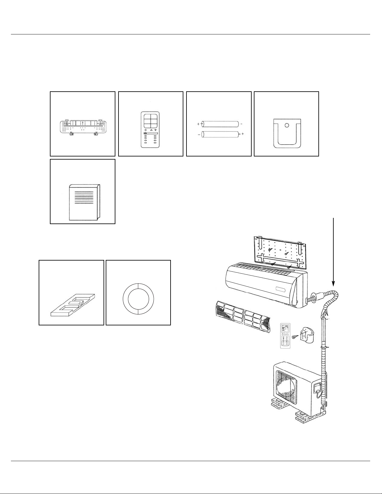
The following accessories are supplied with the air conditioner.
• The quantities are indicated in parenthesi s.
Installation plate (1) Remote control (1)
“AAA” batteries for
remote control (2)
Remote control
holder (1)
Accessories in the Indoor Unit Case
Owner’s manual (1)
Installation manual (1)
Service manual (1)
Warranty (1)
Rubber leg (4)
Interconnecting wiring and conduits
from the outdoor unit to the indoor unit
are not provided with the air conditioner.
Wall plastic sleeve (1)
Accessories in the Outdoor Unit Case
Installation & service manual _2
ACCESSORIES
Page 6
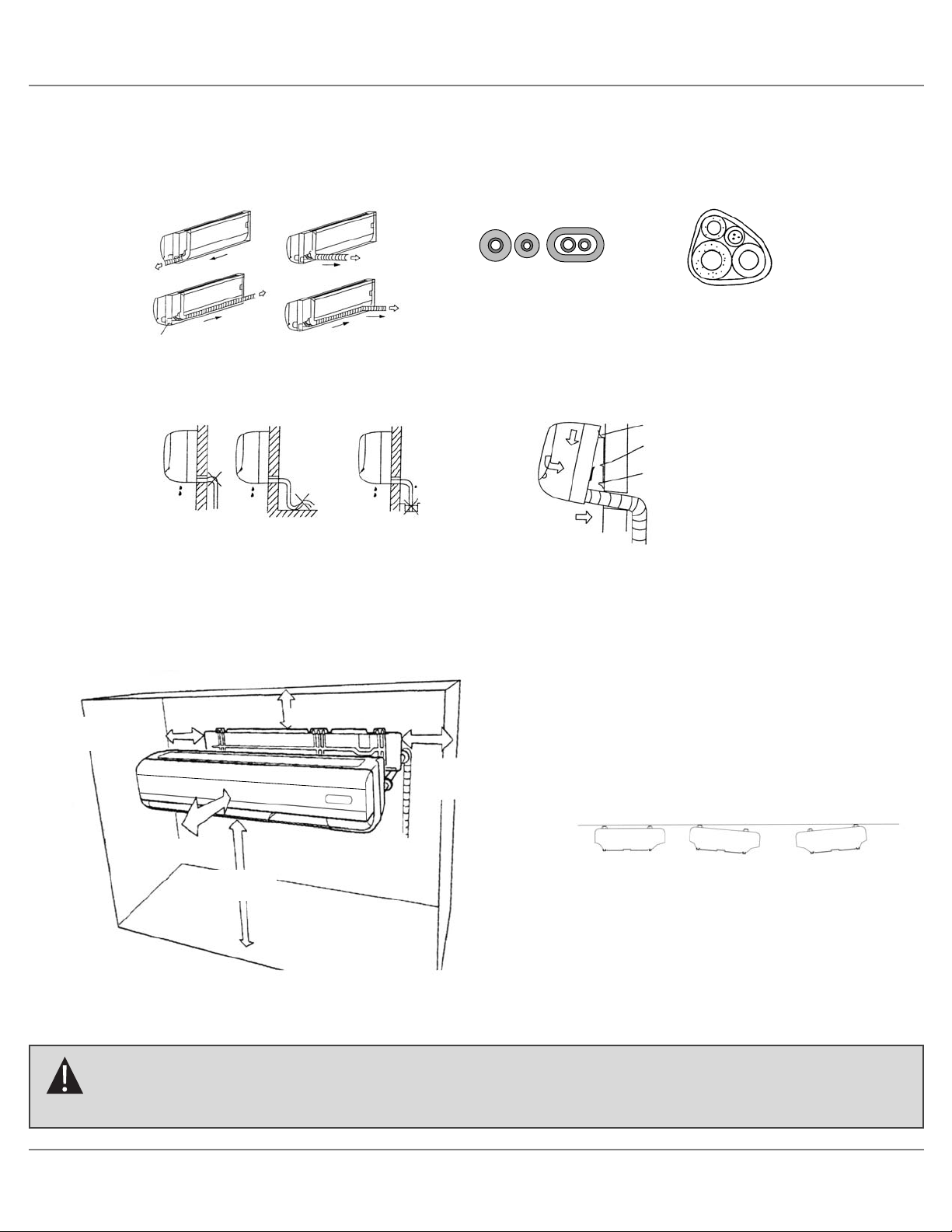
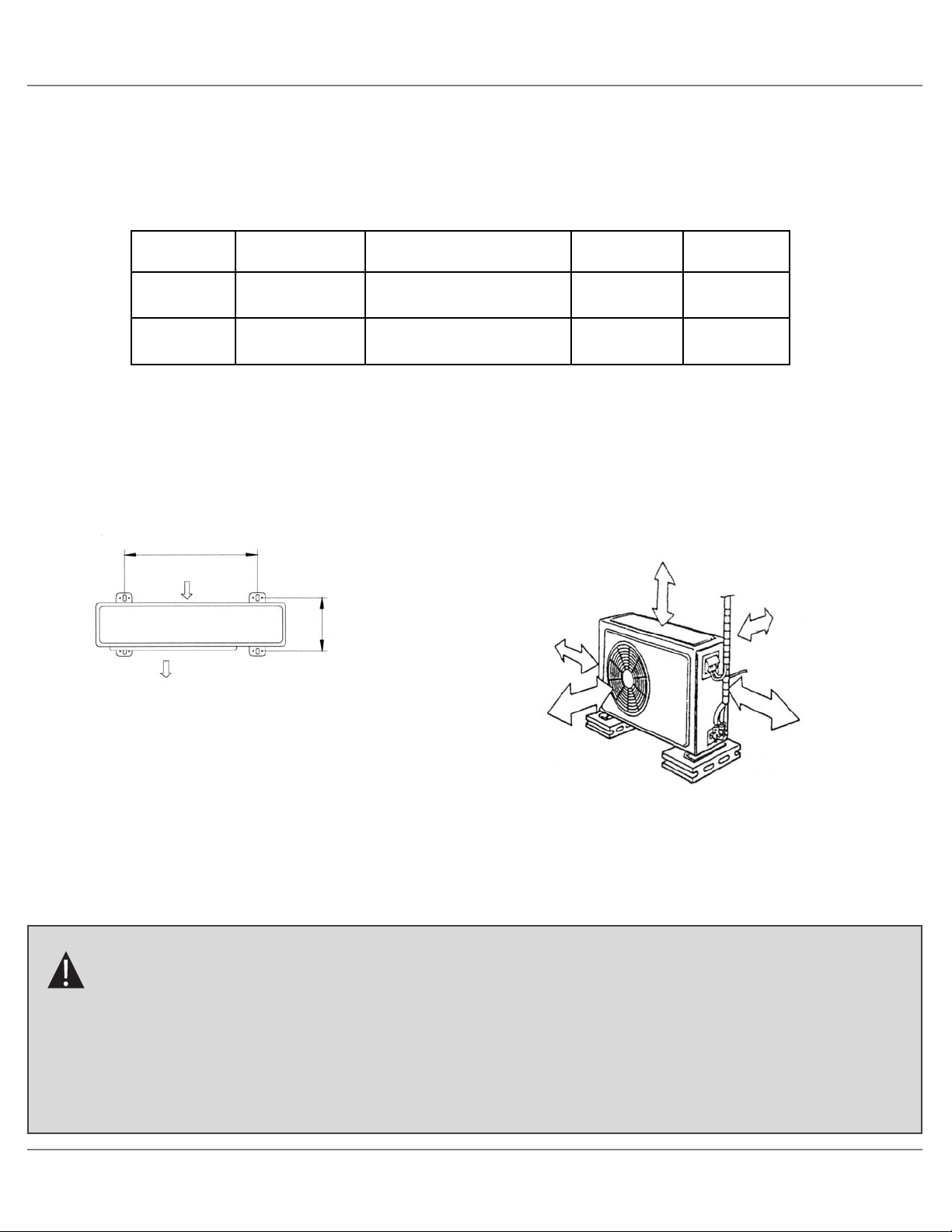
1. Before fixing the installation plate to a wall, you must determine the position of the 2
3
/
4 in (70 mm) hole through which
the conduit, piping and drain hose pass to connect the indoor unit to the outdoor unit. The piping and conduit can be connected from the: Rear, Right or Left side of indoor unit.
2. Determine the position of the pipe and drain hose hole using one of the figures shown, and drill the hole with an inner
diameter of 70 mm (2
3
/
4 inch) so that it slants slightly downwards.
3. The correct mounting of the indoor unit is as shown below.
CORRECT
INCORRECT
POSITION THE MOUNTING PLATE LEVEL
CORRECT
INCORRECT
INCORRECT
Right side 2 in
minimum
Left side 2 in
minimum
59 to 79 in
minimum
59 in minimum
2 3/8 in minimum
Caution:
Take servicing into consideration and leave the spacing shown in the figure above. Also install the unit where
it can be removed.
Installation & service manual _3
INSTALLATION RECOMMENDATIONS (INDOOR UNIT)
Page 7
Attach the outdoor unit with 4 anchor bolts and nuts (not supplied) positioned as per dimensions A, B.
9SRAO-HE
Caution:
The outdoor unit should not be exposed to strong winds or where it is very dusty.
- Take your neighbors into consideration so that they will not be disturbed by air blowing into their window
or by noise.
- Provide enough space between the wall and the unit, so that the airflow is not blocked. Also, for efficient
operation, leave enough clearance on both sides and front.
24 in minimum
9 in minimum
16 in minimum
24 in minimum
12 in minimum
Air inlet
Air outlet
A
B
Installation & service manual _4
INSTALLATION RECOMMENDATIONS (OUTDOOR UNIT)
12SRAO-HE | 15SRAO-HE
21 3/8
13
18SRAO-HE
24SRAO-HE
13 3/8
25
24 3/8
15
23
15
A (in)
B (in)
Page 8
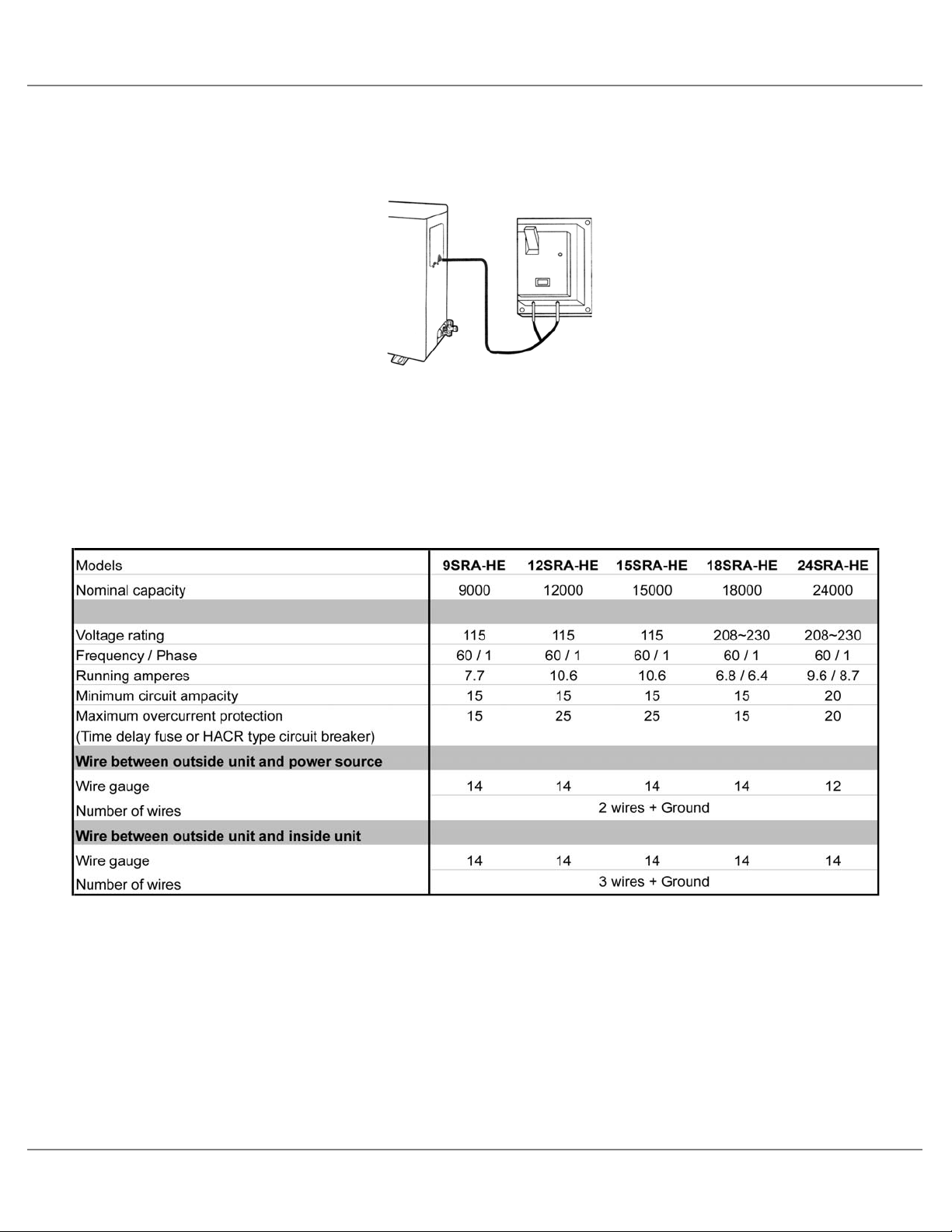
1. The air conditioner shall be installed by a qualified technician in accordance with national and local electrical codes.
2. A disconnect switch shall be installed near the outdoor unit for easy disconnect of power to the air conditioner.
3. An electrical circuit dedicated to the air conditioner shall be used for the power supply to the air conditioner.
4. Interconnecting wiring and conduits from the outdoor unit to the indoor unit are not provided with the air conditioner.
5. The supply voltage, size of over current protective device, and size of supply conductors for the air conditioner are as
shown below.
6. Unit must be installed in accordance with all applicable federal, state and local codes.
7. Check local electrical codes and regulations before obtaining wire.
8. Use copper supply wires only.
9. Each wiring connection must be done tightly and in accordance with the wiring system diagram. Improper wiring may
cause the unit to malfunction or become damaged.
Installation & service manual _5
ELECTRICAL INSTALLATION
BTU
Page 9

3 2 1
Terminal block of indoor unit
3 2 1L1 N
Terminal block
of outdoor unit
Power supply,
1 phase, 60 Hz
INDOOR UNIT OUTDOOR UNIT
Installation & service manual _6
WIRING SYSTEM DIAGRAMS
Ground wire
ACN wire
ACL wire
Communication
wire
9SRA-HE | 12SRA-HE | 15SRA-HE (115V - 60Hz)
INDOOR UNIT
OUTDOOR UNIT
L1
N
3
OUTDOOR UNIT
2
1
INDOOR UNIT WIRING DIAGRAM
3
2
1
ACN
BU
ACL
BN
CMU
OR
INDOOR CONTROL BOARD
FUSE
3.15 A
9
COMPULSIVE SWITCHING
2
PIPE SENSOR
2
TEMP SENSOR
2
5
5
DISPLAY AND
RECEIVE BOARD
IN FAN
STEP
MOTOR
3
2
INDOOR UNIT
1
BN
L1
WH
N
BU
BU
3
BN
ACN
2
OR
1
OUTDOOR UNIT WIRING DIAGRAM
CMU
OUTDOOR CONTROL BOARD
FUSE
3.15 A
COM
NO
CAPACITOR
PROTECTOR
C
5
2
2
RD
R
S
COMPRESSOR
HIGH
PRESSURE
SWITCH
LOW
PRESSURE
SWITCH
OUT
FAN
OUTDOOR TEMP SENSOR
OUTDOOR PIPE SENSOR
Page 10

Installation & service manual _7
WIRING SYSTEM DIAGRAMS
3 2 1
Terminal block of indoor unit
3 2 1L1 L2
Terminal block
of outdoor unit
Power supply,
1 phase, 60 Hz
INDOOR UNIT OUTDOOR UNIT
Ground wire
ACN wire
ACL wire
Communication
wire
18SRA-HE | 24SRA-HE (208-230V - 60Hz)
INDOOR UNIT
OUTDOOR UNIT
L1
L2
3
OUTDOOR UNIT
2
1
INDOOR UNIT WIRING DIAGRAM
3
2
1
ACN
BU
ACL
BN
CMU
OR
INDOOR CONTROL BOARD
FUSE
3.15 A
9
COMPULSIVE SWITCHING
2
PIPE SENSOR
2
TEMP SENSOR
2
5
5
DISPLAY AND
RECEIVE BOARD
IN FAN
STEP
MOTOR
BN
L1
WH
L2
3
2
INDOOR UNIT
1
BU
BU
3
BN
2
OR
1
OUTDOOR UNIT WIRING DIAGRAM
ACN
COM
FUSE
3.15 A
CMU
OUTDOOR CONTROL BOARD
CAPACITOR
PROTECTOR
NO
RD
R
C
COMPRESSOR
HIGH
PRESSURE
SWITCH
LOW
PRESSURE
SWITCH
5
OUT
FAN
OUTDOOR TEMP SENSOR
2
S
Page 11

1. The indoor unit is powered from the outdoor unit. A sufficient length of conduit and wiring shall be used from the
outdoor unit to the indoor unit.
2. To access the terminal block inside the indoor unit, remove the screw on the cover plate. (See Fig. A.)
3. Connect the inter unit conductors to terminals marked 1,2,3, on the indoor unit corresponding to the same numbered
terminals from the outdoor unit. (See Fig.B.)
Figure B
Terminal block of indoor unit
Installation & service manual _8
ELECTRICAL CONNECTIONS FOR INDOOR AND OUTDOOR UNITS
Terminal block
Cover plate
Figure A
INDOOR UNIT
OUTDOOR UNIT
Conduit
Conduit
connectors
Incoming power supply
To indoor unit
1. Two conduit connection openings are provided on the outdoor unit: one for incoming power supply and the second one for
the inter unit wiring.
2. Remove the terminal box cover to access the terminal block.
3. Connect the power supply conductors to terminal marked L1, N or L1, L2, and the grounding wire to terminal
marked .
4. Connect the inter unit conductors to terminals marked , 3, 2, 1.
Conduit
Conduit
connectors
Incoming power supply
To indoor unit
9SRA-HE | 12SRA-HE | 15SRA-HE (115V - 60Hz)
18SRA-HE | 24SRA-HE (208-230V - 60Hz)
Page 12

When connecting the refrigerant tubing
- Keep all tubing runs as short as possible.
- Use the flare method for connecting tubing.
- Apply refrigerant lubricant to the matching surfaces of the flare and union tubes before connecting them, then tighten
the nut with a torque wrench for a leak-free connection.
- Check carefully for leaks before starting the test run.
Evaporator
Condenser
Compressor
Capillary tube
3-Way valve
2-Way valve
Indoor unit
Outdoor unit
Installation & service manual _9
REFRIGERATION LINE CONNECTIONS
Models 9SRA-HE 12SRA-HE 15SRA-HE 18SRA-HE 24SRA-HE
Refrigeration Tubing
Connection method Flare Flare Flare Flare Flare
Refrigerant tube outer diameter in. Liquid 1/4 1/4 1/4 1/4 3/8
in. Suction 1/2 1/2 1/2 5/8 5/8
Limit of tubing length ft. 49 49 49 49 49
Limit of elevation difference between the two units ft. 20 20 20 20 20
Page 13

Installation & service manual _10
REFRIGERANT R410A: SPECIAL PRECAUTIONS WHEN INSTALLING UNIT
General Information
Systems using R-410A refrigerant run at a pressure of approximately 1.6 times that of similar systems using R-22 and the
energy efficiency is comparable. The R-410A refrigerant is a 50:50 mixture of R-32 and R-125.
When installing equipment using R-410A refrigerant, there are a number of standards that must be met:
• Ester oil is used for R-410A.
• It’s important to work with absolute cleanliness.
• Brazing must be done with the use of Nitrogen.
• The system must always be charged in the liquid state.
When refrigerant R-410A is used, the composition will differ depending on whether or not it is a gaseous state.
Consequently, always charge the refrigerant while it is in a liquid state.
General Precautions – Refrigerant leaking
The composition of refrigerant R-410A changes when it is gaseous state. Thus, when there is a refrigerant leak the basic
performance of the air conditioner may be degraded because of a change in composition of the remaining refrigerant.
Therefore, do not add new refrigerant. Instead, recover the remaining refrigerant with the refrigerant recovery unit. Then,
after evacuation, totally recharge the unit with the specified amount of new refrigerant at it’s normal mixed composition state.
Tubing Precautions
The refrigerant R-410A is less is more easily affected by dust or moisture than R-22 refrigerant. Make sure to temporally
cover the ends of the tubing with caps or tape prior installation.
Never use tubing which is less than 0.03 inch in thickness (Standard Specification ASTM B-280), since air conditioners with
R-410A refrigerant are subject to higher pressures than those using R-22 refrigerant.
Caution:
The compressor POE oil for R-410A units is extremely susceptible to moisture absorption and could cause
compressor failure. Do not leave system open to atmosphere any longer than necessary for installation.
Page 14

Installation & service manual _11
TIGHTENING REFRIGERANT PIPING CONNECTIONS
Caution:
Remove the protection caps on the pipes and connect the assembly piping to each connector. First,
tighten the nuts manually and then with a wrench by applying the tightening torque shown below.
17 x 14 to 18
22 x 34 to 42
26 x 49 to 61
29 x 68 to 82
36 x 100 to 120
Class 2 (for R410A)
Diamètre (mm) x Tightening torque (Nm)
Applicable size
1/4 “
3/8 “
1/2 “
5/8 “
3/4 “
Flare nut size and tightening torque
Page 15

Installation & service manual _12
SYSTEM EVACUATION
Condensing unit liquid and suction valves are closed to contain the charge within the unit. The unit is shipped with the valve
stems closed and caps installed. Do not open the valves until the system is evacuated.
1. Connect the vacuum pump with 250-micron capability to the services valves.
2. Evacuate the system to 250 microns or less using suction and liquid service valves. Using both valves is necessary for some
compressors create a mechanical seal separating the sides of the system.
3. Close pump valve and hold vacuum for 10 minutes. Typically pressure will rise during this period
• If the pressure rises to 1000 microns or less and remains steady the system is considered leak-free; proceed to startup.
• If the pressure rises above 1000 microns but holds steady below 2000 microns, moisture and/or noncondensibles may
be present or the system may have a small leak. Return to step 2: If the same result is encountered, check for leaks as
previously indicated and repair as necessary then repeat evacuation.
• If pressure rises above 2000 microns, a leak is present. Check for a leaks as previously indicated and repair as
necessary then repeat evacuation.
Manifold valve
Low pressure side valve
High pressure side valve
Charging hose
Vacuum pump
A
B
Charging hose
Caution:
Refrigerant must not be discharged into the atmosphere.
After connecting the piping, check the joints for leakage with a gas leak detector.
Page 16

Installation & service manual _13
ADDITIONAL CHARGE AND DISTANCE
Refrigerant suitable for a piping length of 20 ft (6 m) is charged in the outdoor unit at the factory. When the pipe is longer
than 20 ft (6 m), additional charging is necessary. This operation can only be performed by a qualified refrigeration
specialist. Additional amount must be added for each extra 3.3 ft (1 m), see the table below:
Models
Limit of tubing length
ft (m)
Limit of elevation
between the two unit
20 (6)
Models
Additional refrigerant 20 g (0.7 oz)
30 g (1.06 oz)
40 g (1.41 oz)
9SRA-HE
12SRA-HE | 15SRA-HE |
18SRA-HE
24SRA-HE
9SRA-HE | 12SRA-HE | 15SRA-HE | 18SRA-HE | 24SRA-HE
49 (15)
Page 17

Installation & service manual _14
GAS LEAK CHECK
Check that no gas escapes from the connections by using a leak detector or soapy water.
A and B are the liquid and suction valves of the outdoor unit.
C and D are the extremities of the indoor unit flared connections.
Indoor unit check points
B
A
D
Liquid and suction valves
C
Page 18

Installation & service manual _15
CHECKING AND TESTING OPERATIONS
Perform the operation test after completing the gas leak check of the flare nut connections and the electrical connections.
1. To begin the test, turn on the power.
2. Press the auxiliary control button in the indoor unit or use the remote control to start the unit.
3. Check that all air conditioner functions are operating normally. A protection feature prevents the air conditioner from
being started immediately after the unit has been turned off. There is a delay of 3 minutes for the air conditioner to restart
and operate.
4. Press the auxiliary control button to end the operation test.
15 000-18 000-24 000 BTU
9 000-12 000 BTU
Auxiliary control button
Auxiliary control button
Page 19

Installation & service manual _16
TECHNICAL SPECIFICATIONS
SPECIFICATIONS
*Note: Design and specifications are subject to change without notice for product improvement.
Comply with ARI STANDARD 210/240.
Cooling
Cooling
Maximum
Minimum
Maximum
Minimum
Cooling
Liquid
Suction
Width
Height
Depth
Shipping
Net
Width
Height
Depth
Shipping
Net
12SRA-HE
12 000
13.5
R-410A
3.1
441
45-42-34
52
95 (35)
64 (18)
109 (43)
32 (0)
115
60 / 1
10.6
15
25
Flare
1/4
1/2
49
20
31 1/2
10 7/8
8 1/4
22
19
33 7/8
25 5/8
12
101
95
9SRA-HE
9 000
15
R-410A
1.9
382
44-40-33
50
95 (35)
64 (18)
109 (43)
32 (0)
115
60 / 1
7.7
15
15
Flare
1/4
1/2
49
20
31 1/2
10 7/8
8 1/4
22
19
31 3/4
23 1/2
11 1/4
92
88
15SRA-HE
15 000
14
R-410A
3.5
559
47-44-40
55
95 (35)
64 (18)
109 (43)
32 (0)
115
60 / 1
10.7
15
25
Flare
1/4
1/2
49
20
38 3/4
12 5/8
7 1/2
33
29
33 7/8
25 5/8
12
101
95
18SRA-HE
18 000
13.5
R-410A
4.1
647
48-44-40
56
95 (35)
64 (18)
109 (43)
32 (0)
208~230
60 / 1
6.8 / 6.4
15
15
Flare
1/4
5/8
49
20
38 3/4
12 5/8
7 1/2
33
29
37 1/2
33 3/4
13 3/4
139
130
24SRA-HE
24 000
13
R-410A
5.2
765
52-49-45
59
95 (35)
64 (18)
109 (43)
32 (0)
208~230
60 / 1
9.6 / 8.7
20
20
Flare
3/8
5/8
49
20
42 1/2
13
9 1/4
39
35
38 1/4
37 1/2
14 1/4
150
141
BTU/h
BTU/hW
Pt./H
CFM
dB(A)
dB(A)
°F (°C)
°F (°C)
V
Hz / ø
A
A
A
in.
ft.
ft.
in.
lbs
in.
lbs
MODELS
Performance ratings
Nominal capacity
S.E.E.R
Refrigerant type
Dehumidifying capacity
Airflow circulation (High)
Indoor sound rating (High-Medium-Low)
Outdoor sound rating
Temperature Indoor air intake
Outdoor air intake
Electrical data
Voltage rating
Frequency / Phase
Running amperes
Minimum circuit ampacity
Maximum overcurrent protection
(Time delay fuse or HACR type circuit breaker)
Refrigeration tubing
Connection method
Refrigerant tube outer diameter
Limit of tubing length
Limit of elevation difference between the two units
Dimensions & weight
Indoor unit Dimensions
Weight
Outdoor unit Dimensions
Weight
Page 20

In
A
B
C
D
E
F
G
H
I
Models: 9SRA-HE | 12SRA-HE | 15SRA-HE | 18SRA-HE | 24SRA-HE
Indoor unit
Outdoor unit
A
F
B
D
E
H
I
G
C
Installation & service manual _17
OUTLINE AND DIMENSIONS
9SRA-HE
10 7/8
31 1/2
8 1/4
31 3/4
11
23
1/2
11 1/4
14 1/8
12SRA-HE
10 7/8
31 1/2
8 1/4
33 7/8
12
25
5/8
12
14 3/4
15SRA-HE
12 5/8
38 3/4
7 1/2
33 7/8
12
25
5/8
12
14 3/4
18SRA-HE
12 5/8
38 3/4
7 1/2
37 1/2
14
32 1/4
1 1/2
13 3/4
16 1/4
24SRA-HE
13
43 1/2
9 1/4
38 1/4
14 1/2
36
1 1/2
14 1/4
16 1/4
Page 21

Installation & service manual _18
PARTS DIAGRAM (INDOOR UNIT)
INSIDE UNIT
9SRAI-HE
12SRAI-HE
15SRAI-HE
18SRAI-HE
24SRAI-HE
Page 22

Installation & service manual _19
PARTS LIST (INSIDE UNIT)
Inside unit - spare parts
REF.
NO
Faceplate (including display glass) 1
1
Lamp board holder 1
2
Lamp Board (3 lights) + infrared lense 1
3
Lamp board back cover 1
4
5 Control Box Cover 1 P00851 P00851
Terminal block Cover 1
6
Plastic Cover 1
7
8 Filters 2 P00858 P00858
9 Middle Base 1 P00861 P00861
10 Rating plate (WILLIAMSON) 1 L00140 L00141
Wiring circuit diagram 1 L00027 L00027 L00027 L00027 L00027
11
12 Wireless remote control 1
13 Wireless remote control holder 1
Terminal Block 1 P00876 P00876 P00876 P00876 P00876
14
Nameplate (WILLIAMSON) 1 L00138 L00138 L00138 L00138 L00138
15
Control Box 1
16
Controller PCB 1
17
18 Sensors 1
Sensor Bracket 1 P00883 P00883 P00883 P00883 P00883
19
Rubber plug (back drain) 1 P00884 P00884 P00885 P00885 P00885
20
Fan Motor Assembly kit
21
Fan motor cushion 1
21-1
Fan motor
21-2
Evaporator Assembly
22
Cross Flow Fan Assembly
23
Cross Flow Fan
23-1
Cushion - Cross flow fan
23-2
Left Cover (Cross flow fan) 1
24
Drain Hose 1
25
Blade (vertical movement) 1 or 2
26
27 Fan guard metal grid 1
Discharge frame assembly 1
28
Step Motor 1
29
30 Louvers (horizontal movement) 2 P00925 P00925 P00926 P00926 P00927
Base Assembly 1
31
Wall Hook Bracket 1
32
Screw cap 3
33
DESCRIPTION QTY
1
1 P00895 P00895 P00896 P00896 P00897
kit K00090 K00090 K00091 K00091 K00092
1 P00901 P00901 P00902 P00902 P00903
1 P00904 P00904 P00905 P00905 P00906
9SRAI-HE 12SRAI-HE 15SRAI-HE 18SRAI-HE 24SRAI-HE
P00843 P00843
P00846 P00846
P00847 P00847
P00850 P00850
P00854 P00854
P00855 P00855
P00874 P00874 P00874 P00874 P00874
P00875 P00875 P00875 P00875 P00875
P00878 P00878
P00881 P00868 P00869 P00870 P00871
P00882 P00882 P00882 P00882 P00882
K00086 K00086 K00087 K00088 K00089
P00889 P00889 P00890 P00872 P00891
P00892
P00907 P00907 P00908 P00908 P00909
P00910 P00910 P00911 P00911 P00912
P00913 P00913 P00914 P00914 P00915
P00916 P00916 P00917 P00917 P00918
P00919 P00919 P00920 P00920 P00921
P00877 P00877 P00886 P00886 P00924
P00928 P00928 P00929 P00929 P00930
P00931 P00931 P00932 P00932 P00933
P00898 P00898 P00899 P00899 P00900
P00892 P00893 P00873 P00894
P00844 P00844 P00845
P00864 P00864 P00865
P00848 P00848 P00849
P00866 P00866 P00867
P00852 P00852 P00853
P00856 P00856 P00857
N/A N/A N/A
P00859 P00859 P00860
P00862 P00862 P00863
L00142 L00143 L00144
P00879 P00879 P00880
Page 23

Installation & service manual _20
PARTS DIAGRAM (OUTDOOR UNIT)
OUTSIDE UNIT
9SRAO-HE
12SRAO-HE
15SRAO-HE
18SRAO-HE
24SRAO-HE
Page 24

Installation & service manual _21
PARTS LIST (OUTSIDE UNIT)
Outside unit - spare parts
REF.
NO
1 Cabinet | Front L | Painted (including fan cover) 1 P00730 P00731 P00731 P00732 P00733
2 Control box cover 1 P00734 P00734 P00734 P00734 P00734
3 Propeller fan 1 P00738 P00738 P00738 P00739 P00739
4 Motor bracket 1 P00740 P00741 P00741 P00742 P00743
5 Fan motor 1 P00744 P00744 P00744 P00745 P00745
6 Nameplate (WILLIAMSON) 1 L00139 L00139 L00139 L00139 L00139
7 PCB outdoor 1 P00747 P00747 P00747 P00748 P00748
8 Control box 1 P00749 P00735 P00735 P00750 P00751
9 Capacitor | Compressor 1 P00752 P00752 P00752 P00754 P00755
10 Capacitor clamp 1 P00756 P00756 P00756 P00758 P00736
11 Terminal block 1 P00757 P00757 P00757 P00759 P00759
12 Divider wall 1 P00760 P00761 P00761 P00737 P00762
13 Cabinet | top | Painted 1 P00763 P00764 P00764 P00746 P00765
14 Condenser assembly 1 P00766 P00767 P00767 P00768 P00769
15 Cabinet | Front R | Painted 1 include with ref. #1 include with ref. #1 include with ref. #1 P00753 include with ref. #1
16 Base Assembly / Painted 1 P00770 P00771 P00771 P00773 P00774
17 Capillary assembly 1 P00775 P00776 P00776 P00777 P00777
18 Compressor assembly Kit K00082 K00083 K00083 K00084 K00085
18-1 Compressor 1 P00783 P00784 P00784 P00785 P00786
18-2 Special nut | M8 3 P00787 P00787 P00787 P00787 P00787
18-3 Rubber seat 3 P00791 P00791 P00791 P00793 P00794
18-4 Terminal gasket 1 P00795 P00795 P00795 P00797 P00797
18-5 Terminal cover 1 P00799 P00799 P00799 P00801 P00801
19 Noise insulation 1 P00803 P00803 P00803 P00805 P00805
20 Sensor bracket 1 P00807 P00807 P00807 P00807 P00807
21 Rubber caps 2 P00811 P00811 P00811 P00811 P00811
22 Steel Grid 1 P00812 P00813 P00813 P00814 P00815
23 Cabinet | Back R | Painted 1 P00816 P00817 P00817 P00818 P00819
24 Side plastic cover 1 P00820 P00821 P00821 P00823 P00824
25 Electric Diagram 1 L00028 L00028 L00028 L00029 L00029
26 Rating Plate (WILLIAMSON) 1 L00145 L00146 L00147 L00148 L00149
27 Two-Way valve (Liquid) 1 P00831 P00832 P00832 P00830 P00833
28 Three-Way valve (Succion) 1 P00829 P00834 P00834 P00835 P00836
29 Valve panel 1 P00837 P00838 P00838 P00839 P00840
30 Outdoor heat exchanger thermistor 1 P00841 P00841 P00841 P00841 P00841
31 Discharge temperature thermistor 1 P00842 P00842 P00842 P00842 P00842
32 Rubber legs 4 P00772 P00772 P00772 P00772 P00772
33 Low pressure switch 1 P00945 P00945 P00945 P00945 P00945
34 High pressure swicth 1 P00946 P00946 P00946 P00946 P00946
DESCRIPTION QTY
9SRAO-HE 12SRAO-HE 15SRAO-HE 18SRAO-HE 24SRAO-HE
Page 25

Installation & service manual
NOTE
Page 26

8201 W. Calumet Road, Milwaukee, WI 53223 USA
www.williamson-thermoflo.com
 Loading...