

Page 1
1
6
4
3
2
HL1
5
7
2
8
HL2
5
9
10
11
User Guide
Telephone Handset
Lifter Accessory
Models HL1 & HL2
345 Encinal Street
Santa Cruz, California 95060
800.544.4660
www.plantronics.com
Printed in the U.S.A. 65688-01 ©10•200 3 Plantronics Inc.
C
HARDWARE SETUP
LIFTER OPERATION
The handset/headset bar on the A20 amplifier will activate the lifter to
make or receive a call.
A
D
D
HL2 TELEPHONE HANDSET LIFTER ACCESSORYHL2 DIAGRAM HL2 TELEPHONE HANDSET LIFTER ACCESSORY
WARRANTY AND SERVICE
LIMITED WARRANTY
for Plantronics Commercial Products
Purchased in the US and Canada
• This warranty covers defects in materials and workmanship of
Commercial Products manufactured, sold or certified by Plantronics
which were purchased and used in the United States and Canada.
• This warranty lasts for two years from the date of purchase of the
Products.
• This warranty extends to you only if you are the end user with the origi-
nal purchase receipt.
• We will, at our option, repair or replace the Products that do not conform
to the warranty. We may use functionally equivalent reconditioned/
refurbished/remanufactured/pre-owned or new Products or parts.
• To obtain service in the U.S. contact Plantronics at (800) 544-4660
and in Canada call (800) 540-8363. If you need additional i
nformation, please contact our service centers at the numbers provided.
• THIS IS PLANTRONICS’ COMPLETE WARRANTY FOR THE PRODUCTS.
• This warranty gives you specific legal rights, and you may also have
other rights which vary from state to state or province to province.
Please contact your dealer or our service center for the full details of our
limited warranty, including items not covered by this limited warranty.
Copyright 2003 Plantronics, Inc. All rights reserved.
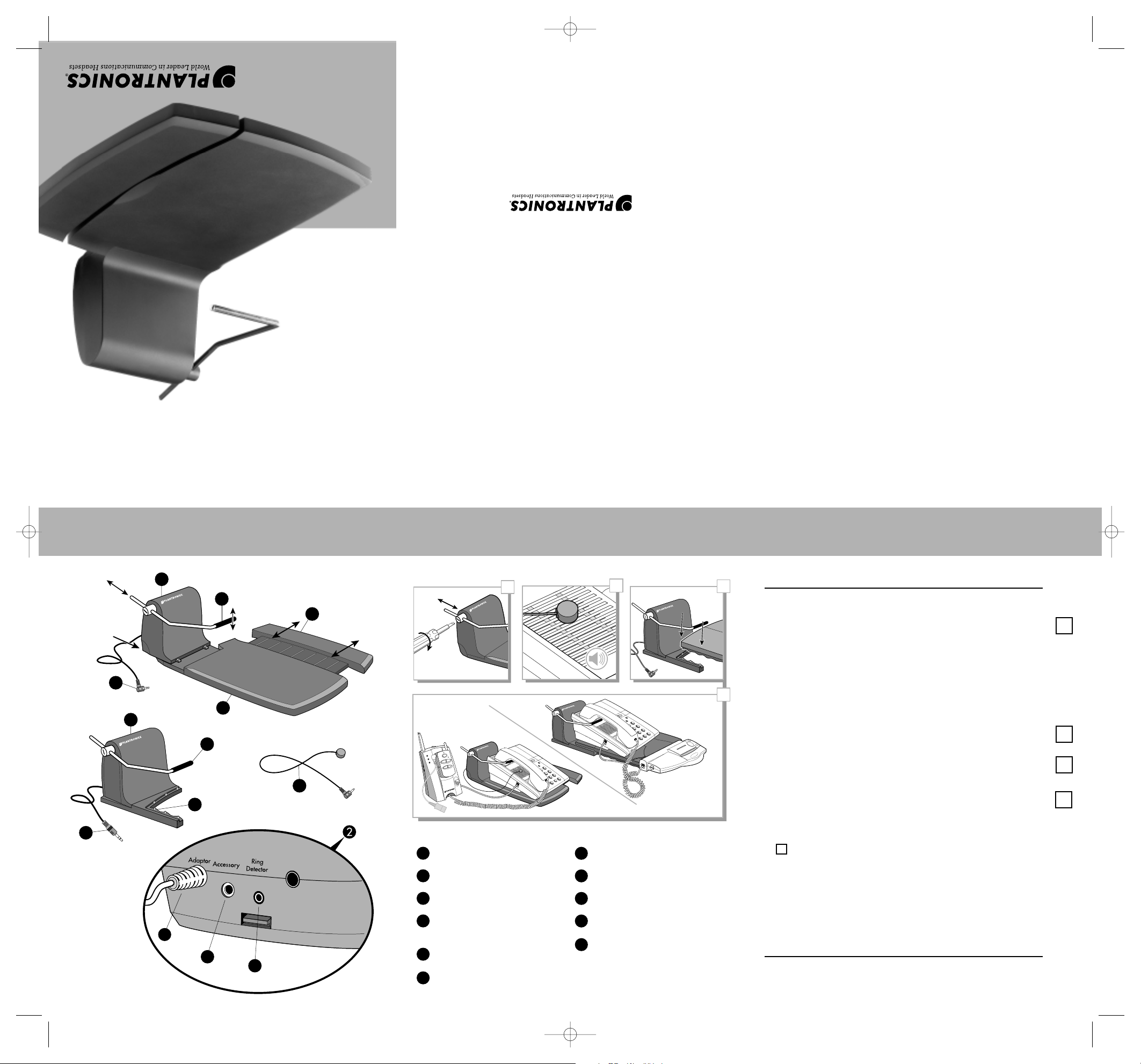
HL1 Adapter Power Plug
Lifter Motor Assembly
HL1 Expandable Base
HL1 Ringer Detector
and cable P/N 46780-01
Lifter Arm P/N 46778-01
HL1 Lifter Base
HL2 Adapter Housing
HL2 Adapter Power Plug
Adapter Power Line
Accessory Jack
Ringer Detector Jack
(only with the HL1 Lifter)
1728394105
6
11
FOR THE A20 TELEPHONE HEADSET AMPLIFIER
Snap the Lifter Motor Assembly with the A20 Adapter Housing
to the A20 accessory deck.
Connect the Adapter Power Plug to the aux jack of the A20
amplifier. The aux jack on the A20 amplifier is normally used for
the on line Indicator (OLI). If you plan to use the OLI, connect the
OLI plug to the Accessory Jack on the back side of the Lifter
Motor Assembly .
Route the associated wiring for the A20 amplifier through the
accessory deck as illustrated in the A20 User Guide.
Replace the A20 accessory deck lid and place your telephone on the
accessory deck.
Move and/or slide the Lifter Arm to a position near the top of the
earpiece of the telephone handset. Tighten the adjusting screw firmly
with a screw driver or small coin to prevent it from coming loose.
To test the Lifter, depress the handset/headset selector bar on the A20
amplifier and the Lifter Arm will automatically pick up your handset.
Push it again to have the unit return the telephone to its original
position.
You may need to manually readjust the lifter arm to the position shown
in .
Repeat this process until the Lifter can pick up and put down the
telephone handset without error.
No other connections are required. The Lifter will be powered
directly by the A20 amplifier.
You are now ready to make or receive calls.
D
18890 Plx. HL1_HL2 11/17/03 6:39 PM Page 1
A
HL1
B
HL2
C
HL1
CA10
er
w
o
P
k
l
a
T
e
g
r
a
h
C
K
L
A
T
E
T
U
M
L
E
N
N
A
H
C
E
M
U
L
O
V
+
–
HL2
A20
D
Page 2
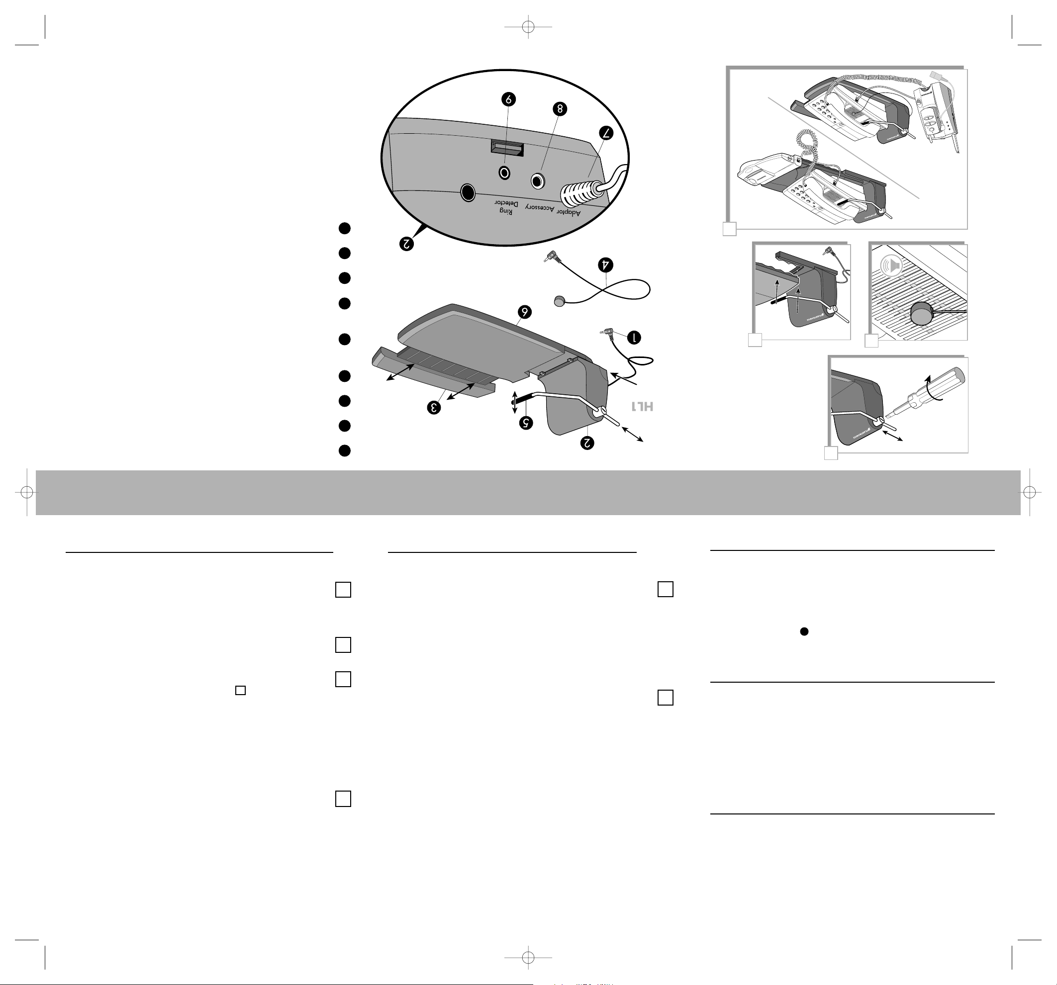
HL1 Adapter Power Plug
Lifter Motor Assembly
HL1 Expandable Base
HL1 Ringer Detector and cable
P/N 46780-01
Lifter Arm
P/N 46778-01
HL1 Lifter Base
Adapter Power Line
Accessory Jack
Ringer Detector Jack
HL1
HL2
A20
CA10
A
HL1
B
D
HL2
C
–
+
V
O
L
U
M
E
C
H
A
N
N
E
L
M
U
T
E
T
A
L
K
P
o
w
e
r
T
a
lk
Ch
arge
HARDWARE SETUP
FOR THE CA10 CORDLESS TELEPHONE HEADSET AMPLIFIER
Slide the Lifter Motor Assemblyinto the LHL1 Base until it locks
in. Avoid trying to snap it in, it slides in easily.
Connect the Adapter Power Plugto the lifter jack on the base
of the CA10 Cordless Telephone Headset Amplifier.
Loosen the Lifter Arm screw and insert the Lifter Arm into the
shaft. Leave the screw untightened for now.
Position your telephone on the Lifter Base so that the lifter arm
is under the handset, near the earpiece. You may need to manually
readjust the lifter arm to the position shown in . You will hear
gear whine during up-down adjustment. This will not hurt the device.
Once in place, tighten the lifter arm screw.
Depress the Talk button on the CA10 base or remote unit and
the Lifter will automatically pickup your handset so that you hear
a dial tone.
Connect the Ring Detector Cableto the Ring Detector Jack
located on the back of the Lifter Assembly.
Remove the tape from the Ring Detector Sensor and attach the
sensor to a position closest to the telephone ringer/speaker.
The Ring Detector Sensor is a little cylindrical microphone located
at the end of the Ring Detector Cable.
Make sure your remote unit “ringer” switch is in the “on” position.
Have someone call you. Your remote unit should ring when your
telephone rings.
You are now ready to receive calls up to 150 feet from your
telephone.
D
HL1 TELEPHONE HANDSET LIFTER ACCESSORY
HL1 TELEPHONE HANDSET LIFTER ACCESSORY
MAKING AND RECEIVING A CALL (Near your telephone)
Put on your headset and depress the talk button on the CA10
base or remote unit. This action activates the lifter to take the
telephone handset off the hook.
When your call is complete, push the talk button again on
the CA10 base or remote unit. The lifter will then return the
telephone handset to its original position.
RECEIVING A CALL (Using the CA10 remote unit away from
your telephone)
The Ring Detector detects a ring from the lifter on your telephone
and transmits the ring to the remote unit which rings. When the talk
button is pushed (on the remote unit ), a signal is sent to the Lifter
which will lift the telephone handset off the telephone. You may
now talk to your calling party.
Press the talk button to hang-up.
NOTE: When using the speakerphone feature of your phone,
turn the ringer off on the CA10 remote. Using the speakerphone
will confuse the ring detector.
LIFTER OPERATION
TROUBLESHOOTING
12345
6
789
HL1 DIAGRAMHL1 DIAGRAM HL1 DIAGRAM KEY
D
A
B
B
D
I CANNOT HEAR A DIAL TONE
On the CA10 amplifier, press the talk button on the CA10 base or
amplifier remote unit.
On the A20 press the headset/handset Bar.
Check that the Adapter Plug and the Ringer Detector
Plug are completely engaged in the back side of the
Lifter Motor Assembly .
ON THE CA10 AMPLIFIER, I HEAR A
RING ON THE TELEPHONE BUT NOT
ON THE REMOTE
Check that the ringer switch on the CA10 remote unit is set to the
“on” position.
Check your ring detector plug and ensure it is plugged in to the Ring
Detector Jack.
Check the location of your ring detector and ensure it is located at the
position of loudest volume.
Your phone’s ringer volume may need to be turned up.
LIFTING ARM HEIGHT VARIES
Tighten the lifting arm retaining screw.
Check the positioning of the phone on the base to be sure it has not
shifted.
Readjust the arm in rest position.
2
C
18890 Plx. HL1_HL2 11/17/03 6:39 PM Page 2
 Loading...