

Page 1
Technical Manual
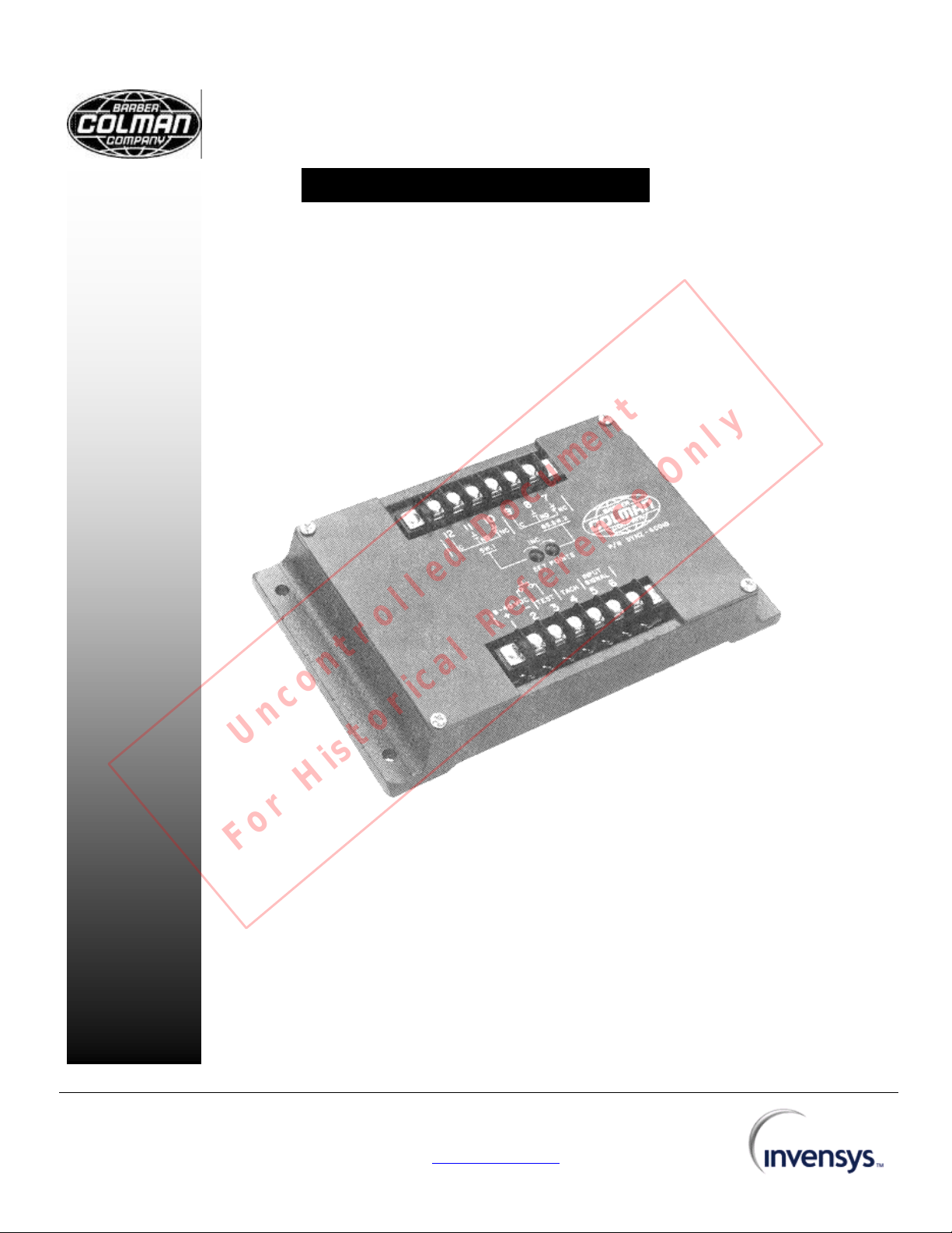
Models
Electronic Speed Switch
Uncontrolled Document
For Historical Reference Only
DYNZ-60010- 8 to 40 Vdc
DYNZ-60012- 59 to 88 Vdc
DYNZ-60013- 8 to 40 Vdc
F-23371
2002 Invensys. All Rights Reserved
Barber-Colman DYNA Products
P.O. Box 2940
1354 Clifford Avenue
Loves Park, IL 61132-2940
USA
Tel: + 1 815 637 3000
Fax: + 1 815 877 0150
www.dynaproducts.com
Page 2

Table Of Contents
1.0 Introduction 1
2.0 Specifications 1
3.0 Additional Features 2
4.0 Wiring Instructions 3
5.0 Operation and Calibration of DYNZ-60010 3
6.0 Operation and Calibration of DYNZ-60012 and DYNZ-60013 4
7.0 Troubleshooting 5
Uncontrolled Document
For Historical Reference Only
2002 Invensys. All Rights Reserved
Page 3

F-23371 Electronic Speed Switch Technical Manual Page 1
Note
Colman believes that all information provided
herein is correct and reliable and reserves the right to
update at any time. Barber0Colman does not assume
essly
Caution
Colman Company
recommends that all engines and turbines be equipped
with an independent overspeed shutdown devise.
1.0 INTRODUCTION
The Barber-Colman two setpoint speed switch
normally obtains its input signal from a magnetic
pickup which is positioned in proximity to the teeth of
a gear on a rotating shaft. The pickup generates an
AC signal voltage whose frequency is directly
proportional to the rate at which the gear teeth pass
by the pole piece. The speed switch converts the
input signal voltage into a DC signal which is
compared to the preset levels (setpoints) and actuate
the relays when the input signal frequency exceeds
the preset values.
Barber-
any responsibility for its use unless otherwise expr
undertaken.
1.1 APPLICATION
l Overspeed Protection Signal
l Underspeed Protection Signal
l Crank Termination Signal
l Generator Field Flashing Signal
l Ignition Signal
l Sequencing Signal
l Tach Signal for Driving Model 40 Tachometer
As a safety measure, Barber-
1.2 RELAY LOGIC TABLE FOR SPEED SWITCHES
Switch
DYNZ-60010
SWl Relay
Contacts
DYNZ-60010
OS-SW2
Relay
Contacts
DYNZ-60012
SW1 Relay
Contacts
DYNZ-60012
OS-SW2
Relay
Contacts
DYNZ-60013
SW1 Relay
Contacts
DYNZ-60013
OS-SW2
Relay
Contacts
Power to Unit
and Input Signal
Frequency
Uncontrolled Document
below Trip Point
De-energized
10 to 12 closed
11 to 12 open
Energized
7 to 9 open
8 to 9 closed
For Historical Reference Only
De-energized
10 to 12 closed
11 to 12 open
De-energized
7 to 9 closed
8 to 9 open
De-energized
10 to 12 closed
11 to 12 open
De-energized
7 to 9 closed
8 to 9 open
Power to Unit and
Input Signal
Frequency above Trip
Point
Energized (nonlatching)
10 to 12 open
11 to 12 closed
De-energized (latched)
7 to 9 closed
8 to 9 open
Energized (nonlatching)
10 to 12 open
11 to 12 closed
Energized (nonlatching)
7 to 9 open
8 to 9 closed
Energized (nonlatching)
10 to 12 open
11 to 12 closed
Energized (nonlatching)
7 to 9 open
8 to 9 closed
2.0 SPECIFICATIONS
2.1 ELECTRICAL
2.1.1 COMMON ELECTRICAL SPECIFICATIONS
FOR DYNZ-60010, DYNZ-60012 AND DYNZ-60013
Ambient Operating Temperature: -40 to +185°F (-
40 to +85°C).
Maximum Operating Current: 0.20 amperes.
Input Signal Voltage: 0 7 Vrms minimum into 33 k
ohm load.
Trip Setpoint: Adjustable 325 to 10,000 Hz.
SW1: Factory set at 1100 Hz.
SW2: Factory set at 3600 Hz.
Repeatability: ±5 Hz or ±1%, whichever is greater.
2.1.2 ELECTRICAL SPECIFICATIONS FOR DYNZ60010
Power Input: 8 to 40 Vdc.
Voltage Transients: Withstand 200 volts forward and
reverse peaks of 10 milliseconds duration at 5 ohms
source input impedance. Withstand 80 volts forward
and reverse peaks of 50 milliseconds duration at 50
ohms source input impedance.
Hysteresis:
SW1: Crank dropout, non-latching; nominal 165 Hz
SW2: Overspeed, latching; 100% of setpoint.
Relay Contact Rating: 10 amperes at 30 Vdc
resistive.
Overspeed Response Time: With the overspeed set
at 4140 Hz and a steady input frequency of 3600 Hz,
then switching the input frequency to 5000 Hz must
result in the overspeed relay operating in 90
milliseconds or less.
2.1.3 ELECTRICAL SPECIFICATIONS FOR DYNZ60012
Power Input: 59 to 88 Vdc.
Voltage Transients: Withstand 200 volts forward and
reverse peaks of 10 milliseconds duration at 50 ohms
source input impedance. Withstand 80 volts forward
and reverse peaks of 50 milliseconds duration at 50
ohms source input impedance.
Hysteresis:
SW1: Crank dropout, non-latching; nominal 165 Hz
SW2: Overspeed, non-latching; 0% of setpoint.
Relay Contact Rating: 0.75 amperes at 88 Vdc
resistive.
Overspeed Response Time: With the overspeed set
at 4140 Hz and a steady input frequency of 3600 Hz,
then switching the input frequency to 5000 Hz must
result in the overspeed relay operating in 75
milliseconds or less.
2.1.4 ELECTRICAL SPECIFICATIONS FOR DYNZ60013
Power Input: 8 to 40 Vdc.
Voltage Transients: Withstand 200 volts forward and
reverse peaks of 10 milliseconds duration at 50 ohms
source input impedance. Withstand 80 volts forward
and reverse peaks of 50 milliseconds duration at 50
ohms source input impedance.
Hysteresis:
SW1: Crank dropout, non-latching; nominal 165 Hz
SW2: Overspeed, non-latching; 0% of setpoint.
2002 Invensys. All Rights Reserved
Page 4

F-23371 Electronic Speed Switch Technical Manual Page 2
Relay Contact Rating: 10.0 amperes at 30 Vdc
resistive.
Overspeed Response Time: With the overspeed set
at 4140 Hz and a steady input frequency of 3600 Hz,
then switching the input frequency to 5000 Hz must
result in the overspeed relay operating in 75
milliseconds or less.
2.2 MECHANICAL / ENVIRONMENTAL
Case: Has nickel plated terminals. Humidity and salt
spray resistant. Potted for water protection.
Vibration: 5.0 G’s from 20 to 500 Hz.
Shock: 4 foot drop test.
2.3 MOUNTING INSTRUCTIONS
Four mounting holes are provided on the case as
shown in Figure 1. Although the unit can withstand
the normal vibration levels and temperature
excursions encountered, it is a good practice to mount
the unit in a location where these effects are
minimized. The unit should be attached to the
mounting plate with 10-32 screws.
Figure 1. Installation Drawing
3.0 ADDITIONAL FEATURES
3.1 OVERSPEED TRIP TESTING
Overspeed trip testing while the engine is running at
its normal speed can be accomplished by temporarily
connecting terminal 2 to terminal 3. This lowers the
overspeed setpoint of OS-SW2 to 67% of its
set/calibrated value.
3.2 TACHOMETER READOUT
Tachometer readout can be obtained by connecting a
Synchro-Start Model 40 tachometer to terminals 1, 2
and 4 as shown in Figure 3.
Figure 2
3.3 SW1 & OS-SW2 ADJUSTMENT AND
ADJUSTMENT RANGE
l There are two speed trip setpoint adjustments,
SW1 and OS-SW2, located on top of the unit. Turning
the 20 turn potentiometer adjustment clockwise
increases the RPM setting.
Uncontrolled Document
For Historical Reference Only
2002 Invensys. All Rights Reserved
Page 5

F-23371 Electronic Speed Switch Technical Manual Page 3
CAUTION
If the 10 ampere relay contact rating is exceeded, the
rcuit board from the relay contacts
NOTE
Omit/skip step 5.2.3 if you are only checking the
NOTE
If you are only checking calibration point, omit steps
l Barber-Colman sets the units to operate over the
adjustment range of 325 to 10,000 Hz by cutting
jumper J2 only. The sensitivity of the adjustment
potentiometer is approximately 480 Hz per turn.
n SW1 is factory set at 1100 Hz unless specified in
purchase order.
n OS-SW2 is factory set at 3600 Hz unless specified
in purchase order.
l The unit can be operated at a lower frequency
adjustment range (80 to 2500 Hz instead of 325 to
10,000 Hz) by reconnecting jumper J2 and cutting out
jumper J1 (see Figure 2).
4.0 WIRING INSTRUCTIONS
The typical wiring diagram shows the wiring required
to properly connect the unit to the DYNA governor. All
the wiring for the test, tach and input power terminals
should be either 18 or 20 AWG wire. The wiring to the
relay contacts should be 16 AWG wire if the current
requirement is less than 5 amperes and 14
AWG if the current through the contacts is between 5
and 10 amperes. The current load and wiring to the
relay should be checked thoroughly.
foil on the printed ci
to the terminals can be damaged.
As shown in Figure 3, a two-conductor shielded cable
must be used for mounting the speed sensor (MPU)
to the unit. The shield should only be connected as
shown. It is good practice to isolate the power wiring
from the relay contacts and associated relays from
the input signal wiring. The input signal is normally
from a magnetic pickup (MPU) mounted on the
flywheel housing which senses the ring gear speed.
5.0 OPERATION AND CALIBRATION OF
Uncontrolled Document
DYNZ-60010
SPEED SWITCH
5.1 OPERATING PROCEDURE
Once the system has been wired, the SPEED
SWITCH functions in the following manner.
5.1.1 No power applied to unit.
l SW1 and OS-SW2 relays are de-energized;
therefore, contacts are in position as shown on top of
unit.
5.1.2 Power is applied to unit when POWER SWITCH
is turned on and no input signal to speed switch.
l SW1 relay remains de-energized; therefore, its
contacts remain in same position as those shown on
top of unit.
l OS-SW2 relay energizes; therefore, its contacts
change states from those shown on top of unit.
5.1.3 When the engine is cranked and the engine
starts, SW1 energizes at its crank-dropout setting
which is normally adjusted midway between the
cranking RPM and idle RPM of the engine.
For Historical Reference Only
5.1.4 When an overspeed condition occurs, OS-SW2
relay deenergizes and latches up and will remain
latched up until the POWER SWITCH is turned off or
power is somehow removed from the unit. The engine
overspeed setpoint is normally adjusted to trip at 10 to
20% above the engine operating speed.
5.2 CALIBRATION PROCEDURE
Equipment Required: Signal generator
Frequency counter Ohmmeter
5.2.1 Determine the desired trip points for your unit
when using a magnetic pickup (MPU).
No. of Gear Teeth x
Trip Point in Hz = Engine RPM Trip Point
60
5.2.2 Connect the signal generator and counter to
terminals 5 and 6 with terminal 5 being the ground
terminal. Set the signal generator frequency 100 Hz
below the SW1 or OS-SW2 trip point you are trying to
calibrate/set or check. Then adjust the out signal from
the signal generator to 1 volt rms or greater.
5.2.3 If you are calibrating unit, turn the desired trip
point potentiometer adjustment 10 or 15 turns
clockwise.
5.3 CALIBRATION OR CHECKING PROCEDURE
FOR SW1 TRIP POINT
5.3.1 With no power applied to unit, connect an
ohmmeter to terminals 10 and 12 (no other wires
attached). The ohmmeter should indicate zero
resistance (short circuit). This is the normally closed
contact on relay SW1.
5.3.2 Apply correct DC power to terminals 1 and 2 of
speed switch. The ohmmeter connected to terminals
10 to 12 should still indicate zero resistance, because
you should be below the setpoint for SW1 and it
should not change states when power is applied to
the unit.
5.3.3 Adjust the signal generator frequency to the
desired SW1 set/trip point as specified or calculated
in step 5.2.1.
5.3.4 Slowly adjust SW1 setpoint potentiometer
counterclock-wise until the ohmmeter indicates an
open circuit. This is now the set/trip point for SW1.
5.3.5 Slowly increase the signal generator frequency
until the ohmmeter connected to terminals 10 to 12
indicates an open circuit. Note the frequency and
verify that it is correct for your SW1 set/trip point
2002 Invensys. All Rights Reserved
Page 6

F-23371 Electronic Speed Switch Technical Manual Page 4
NOTE
If you are only checking calibration point, omit steps
NOTE
ps
NOTE
Omit/skip step 6.2.3 if you are only checking the
requirements. If set/trip point of SW1 is correct it is
properly calibrated. If set/trip point is incorrect, go to
step 5.3.2, 5.3.3 and 5.3.4 and calibrate unit.
5.4 CALIBRATION OR CHECKING PROCEDURE
FOR OS-SW2 TRIP POINT
5.4.1 With no power applied to unit, connect an
ohmmeter to terminals 7 and 9 (no other wires
attached). The ohmmeter should indicate zero
resistance (short circuit). This is the normally closed
contact on relay OS-SW2.
5.4.2 Apply correct DC power to terminals 1 and 2 of
speed switch.
The ohmmeter connected to terminals 7 to 9 should
now indicate infinite resistance (open circuit).
Originally the signal generator frequency was set
below the units set/trip point (see step 5.2.2);
therefore, it must change states when power is
applied.
5.4.3 Adjust the signal generator frequency to the
desired OS-SW2 set/trip point as specified or
calculated in step 5.2.1.
5.4.4 Slowly turn the OS-SW2 potentiometer
adjustment counterclockwise until the ohmmeter
indicates an open circuit. This gives you the correct
setpoint for OS-SW2. Remember OS-SW2 latches.
5.4.5 Slowly increase the signal generator frequency
until the ohmmeter connected to terminals 7 to 9
indicates an open circuit. Note the frequency and
verify that it is correct for your OS-SW2 set/trip point
requirements. If set/trip point of OS-SW2 is correct it
is properly calibrated. If set/trip point is incorrect, go to
step 5.4.2, 5.4.3 and 5.4.4 and calibrate unit.
Uncontrolled Document
6.0 OPERATION AND CALIBRATION OF
DYNZ-60012 AND DYNZ-60013 SPEED
SWITCH
6.1 OPERATING PROCEDURE
Once the system has been wired, the SPEED
SWITCH functions in the following manner.
6.1.1 No power applied to unit.
l SW1 and OS-SW2 relays are de-energized;
therefore, contacts are in position as shown on top of
unit.
6.1.2 Power is applied to unit when POWER SWITCH
is turned on and no input signal to speed switch.
l SW1 relay remains de-energized; therefore, its
contacts remain in same position as those shown on
top of unit.
For Historical Reference Only
l OS-SW2 relay remains de-energized; therefore, its
contacts remain in the same position as shown on top
of unit.
6.1.3 When the engine is cranked and the engine
starts, SW1 energizes (non-latching) at its crankdropout trip point setting which is normally set to trip
midway between the cranking RPM and idle RPM of
the engine.
6.1.4 When an overspeed condition occurs, OS-SW2
relay energizes and it will remain energized until the
frequency falls below the trip point at which time the
relay will de-energize (relay is non-latching with no
hysteresis). The engine over-speed setpoint is
normally adjusted to trip at 10 to 20% above the
engine operating speed.
6.2 CALIBRATION PROCEDURE
Equipment Required: Signal generator
Frequency counter Ohmmeter
6.2.1 Determine the desired trip points for your unit
when using a magnetic pickup (MPU).
No. of Gear Teeth x
Trip Point in Hz = Engine RPM Trip Point
60
6.2.2 Connect the signal generator and counter to
terminals 5 and 6 with terminal 5 being the ground
terminal. Set the signal generator frequency 100 Hz
below the SW1 or OS-SW2 trip point you are trying to
calibrate/set or check. Then adjust the out signal from
the signal generator to 1 volt rms or greater.
6.2.3 If you are calibrating unit, turn the desired trip
point potentiometer adjustment 4 or 5 turns clockwise.
6.3 CALIBRATION OR CHECKING PROCEDURE
FOR SW1 TRIP POINT
6.3.1 With no power applied to unit, connect an
ohmmeter to terminals 10 and 12 (no other wires
attached). The ohmmeter should indicate zero
resistance (short circuit). This is the normally closed
contact on relay SW1.
6.3.2 Apply correct DC power to terminals 1 and 2 of
speed switch. The ohmmeter connected to terminals
10 to 12 should still indicate zero resistance, because
you should be below the trip point for SW1 and it
should not change states when power is applied to
the unit.
If you are only checking calibration point, omit ste
2002 Invensys. All Rights Reserved
Page 7

F-23371 Electronic Speed Switch Technical Manual Page 5
–
CAUTION
–
As a safety measure, the engine should be
equipped with an independent overspeed
ice in the event of failure which
-
NOTE
-
Colman believes that all information
provided herein is correct and reliable but
-
lity for
NOTE
If you are only checking calibration point, omit steps
6.3.3 Adjust the signal generator frequency to the
desired SW1 set/trip point as specified or calculated
in step 6.2.1.
6.3.4 Slowly turn the SW1 setpoint potentiometer
adjustment counterclockwise until the ohmmeter
indicates an open circuit. This gives you the correct
setpoint for SW1.
6.3.5 Slowly increase the signal generator frequency
until the ohmmeter connected to terminals 10 to 12
indicates an open circuit. Note the frequency and
verify that it is correct for your SW1 set/trip point
requirements. If set/trip point of SW1 is correct it is
properly calibrated. If set/trip point is incorrect, go to
step 6.2.3, 6.3.3 and 6.3.4 and calibrate unit.
6.4 CALIBRATION OR CHECKING PROCEDURE
FOR OS-SW2 TRIP POINT
6.4.1 With no power applied to unit, connect an
ohmmeter to terminals 7 and 9 (no other wires
attached). The ohmmeter should indicate zero
resistance (short circuit). This is the normally closed
contact on relay OS-SW2.
6.4.2 Apply correct DC power to terminals 1 and 2 of
speed switch. The ohmmeter should indicate zero
resistance (short circuit) with the signal generator
frequency set below the OS-SW2 set/trip point;
therefore, it must not change states when power is
applied.
6.4.3 Adjust the signal generator frequency to the
desired OSSW2 set/trip point as specified or
calculated in step 6.2.1.
6.4.4 Slowly turn the OS-SW2 potentiometer
counterclockwise until the ohmmeter indicates an
open circuit. This gives you the correct setpoint for
OS-SW2.
6.4.5 Slowly increase the signal generator frequency
until the ohmmeter connected to terminals 7 to 9
indicates zero resistance. Note the frequency and
verify that it is correct for your OS-SW2 set/trip point
requirements. If set/trip point of OS-SW2 is correct, it
is properly calibrated. If set/trip point is incorrect, go to
step 6.2.3, 6.4.3 and 6.4.4 and calibrate unit.
Uncontrolled Document
For Historical Reference Only
7.0 TROUBLESHOOTING PROCEDURE
The unit is potted and, therefore, non-repairable, but
the following checkpoints can be used to determine if
there is an internal fault.
7.1 UNIT DOES NOT FUNCTION
7.1.1 Check battery voltage on terminals 1 and 2.
DYNZ-60010-000-0-40 — 8 to 40 Vdc
DYNZ-60012-000-0-74 — 58 to 88 Vdc
DYNZ-60013-000-0-40 — 8 to 40 Vdc
7.1.2 Check input signal from MPU on terminals 5 and
6 with an AC voltmeter — must be greater than 0.7
volts rms.
7.1.3 Check wiring to speed switch.
7.2 TRIPPING AT WRONG RPM
7.2.1 Check for proper trip point settings.
7.2.2 See calibration section.
7.3 RELAY DOES NOT FUNCTION
7.3.1 Check wiring to relays.
7.3.2 Check relay contacts for proper operation.
shutdown dev
may render the governor inoperative.
Barberreserves the right to update at any time. Barber
Colman does not assume any responsibi
its use unless otherwise expressly undertaken.
2002 Invensys. All Rights Reserved
 Loading...