

Page 1
EN
technical manual
10007462_23
Page 2

Page 3

Chapter A GENERAL & TECHNICAL DATA
1 WARNINGS AND CAUTIONS....................................................... A-1
2 MANUAL VERSIONS .................................................................... A-2
3 TECHNICAL SPECIFICATIONS ................................................... A-3
4 LIST OF TERMS AND ABBREVIATIONS IN THIS MANUAL...... A-6
5 HANDLING PRECAUTIONS FOR PCB’S AND SOFTWARE
CHIPS ............................................................................................ A-7
5.1 Handling printed circuit boards ...................................................................A-7
5.2 Handling software Flash-EPROM chips......................................................A-7
6 EMC INFORMATION..................................................................... A-8
Chapter B CONTROL PANEL FUNCTIONS
1 CONTROL PANEL OVERVIEW.................................................... B-1
TABLE OF CONTENTS
2 NORMAL USER FUNCTIONS ...................................................... B-2
3 USER PROGRAMMING MODE .................................................... B-2
4 PROGRAMMING MODE FUNCTION DETAILS ........................... B-4
4.1 Automatic chair positions ............................................................................B-4
4.2 Instrument spray flow rates......................................................................... B-4
4.3 Chip blow flow rates.................................................................................... B-5
4.4 Fibre optic light intensity .............................................................................B-6
4.5 Polymerization light exposure time .............................................................B-6
4.6 Duration of the bowl rinsing and duration of the glass filling .......................B-7
4.7 Intensity of the operating light .....................................................................B-8
4.8 Duration of the extra function relay activation ............................................. B-8
Chapter C SERVICE MODE
1 GENERAL ABOUT THE SERVICE MODE ................................... C-1
1.1 How to enter service mode .........................................................................C-2
1.2 How to exit service mode and store settings ..............................................C-2
1.3 Navigating among the various service modes ............................................C-3
1.4 Changing an adjustable setting in the service mode ..................................C-3
1.5 Service mode functions short-form .............................................................C-4
Technical Manual
2 SERVICE MODE DETAILED DESCRIPTION ............................. C-17
2.1 MAIN control system related service modes.............................................C-17
2.2 Instrument MUX related service modes....................................................C-22
2.3 Instrument related service modes.............................................................C-26
2.4 Control panel related service modes ........................................................C-27
2.5 Suction holder related service modes.......................................................C-28
Planmeca Compact i Dental Unit TOC - 1
Page 4

TABLE OF CONTENTS
2.6 Foot control related service modes...........................................................C-29
2.7 Operating light related service modes.......................................................C-32
2.8 Patient chair related service modes ..........................................................C-33
2.9 Separator/suction system related service modes .....................................C-34
2.10 MCB CPU direct I/O related service modes (for factory use)....................C-35
2.11 Other service modes .................................................................................C-37
Chapter D HELP & ERROR MESSAGES
1 HELP MESSAGES......................................................................... D-1
1.1 General about help messages ....................................................................D-1
1.2 Help message short-form table...................................................................D-1
2 ERROR MESSAGES ..................................................................... D-6
2.1 General about error messages ...................................................................D-6
2.2 Disabling/enabling error messages.............................................................D-6
2.3 Error message short-form table ..................................................................D-7
3 DETAILED DESCRIPTION OF ERROR MESSAGES................. D-10
3.1 General error messages ...........................................................................D-10
3.2 Power Supply related error messages......................................................D-11
3.3 Control panel related error messages.......................................................D-13
3.4 Instrument related error messages ...........................................................D-13
3.5 Instrument multiplexer related error messages.........................................D-14
3.6 Suction tube holder (STH) related error messages...................................D-17
3.7 Foot control related error messages .........................................................D-18
3.8 Operating light related error messages.....................................................D-19
3.9 Separator system related ..........................................................................D-19
3.10 Patient Chair related .................................................................................D-20
3.11 MAIN CPU related error messages...........................................................D-21
3.12 Headrest related error messages..............................................................D-22
Chapter E PREVENTIVE MAINTENANCE
1 DELIVERY ARMS.......................................................................... E-1
2 SUCTION ARMS............................................................................ E-1
3 INSTRUMENT CONSOLE ............................................................. E-2
4 INSTRUMENTS.............................................................................. E-2
5 FOOT CONTROL........................................................................... E-3
6 CUSPIDOR..................................................................................... E-3
7 CHAIR ............................................................................................ E-4
8 SUCTION SYSTEM........................................................................ E-4
9 OPERATING LIGHT ...................................................................... E-5
TOC - 2 Planmeca Compact i Dental Unit
Technical Manual
Page 5

10 CLEAN WATER SYSTEM..............................................................E-5
11 WATER MANAGEMENT SYSTEM (WMS) ....................................E-6
11.1 Changing the water filter (00271003)..........................................................E-8
Chapter F ADJUSTMENTS
1 MECHANICAL ADJUSTMENTS ....................................................F-1
1.1 Adjusting vertical position of the OP delivery arm column .......................... F-1
1.2 Adjusting friction of the OP delivery arm joints ........................................... F-2
1.3 Adjusting balance of the OP delivery arm................................................... F-3
1.4 Adjusting angle of the OP delivery arm instrument console ....................... F-9
1.5 Adjusting the side delivery arm base joint friction ..................................... F-10
1.6 Adjusting the friction of the side delivery arm joint.................................... F-10
1.7 Adjusting the side delivery arm instrument console friction ...................... F-11
1.8 Adjusting the lifting friction of the side delivery arm .................................. F-11
1.9 Adjusting the tension of the side delivery arm gas spring......................... F-13
1.10 Adjusting friction of the ergo suction arm.................................................. F-15
1.11 Adjusting friction of the adjustable suction arm......................................... F-15
1.12 Removing play of the lifting adapter.......................................................... F-16
1.13 Adjusting the instrument arms .................................................................. F-17
TABLE OF CONTENTS
2 ELECTRICAL ADJUSTMENTS ...................................................F-18
2.1 Calibrating backrest motor position sensor............................................... F-18
2.2 Calibrating lift motor position sensor......................................................... F-20
2.3 Calibrating motorized headrest motor position sensor.............................. F-22
2.4 Rewiring mains voltage selection jumper.................................................. F-25
3 PNEUMATICAL ADJUSTMENTS ................................................F-26
3.1 Adjusting internal water & air pressures ................................................... F-26
3.2 Adjusting syringe water and air flow rates ................................................ F-27
3.3 Adjusting coolants to the instruments ....................................................... F-27
4 WATER MANAGEMENT SYSTEM: ADJUSTING
THE SENSORS ............................................................................F-28
4.1 Preparations before adjustment................................................................ F-28
4.2 Adjusting the lower sensor........................................................................ F-30
4.3 Adjusting the upper sensor ....................................................................... F-30
5 BLEEDING OF THE SPRAY WATER SYSTEM..........................F-31
6 WMS OPERATION .......................................................................F-32
6.1 List of abbreviations .................................................................................. F-32
6.2 WMS operation, normal use ..................................................................... F-32
6.3 WMS operation, WCS use........................................................................ F-35
Technical Manual
Planmeca Compact i Dental Unit TOC - 3
Page 6

TABLE OF CONTENTS
Chapter G PARTS REPLACEMENT & REPAIR
1 REMOVING COVERS....................................................................G-1
2 UPHOLSTERIES REPLACEMENT ...............................................G-3
3 INSTRUMENT MULTIPLEXER RELATED.................................... G-7
3.1 Preparations before instrument multiplexer related replacements............. G-7
3.2 Replacing the whole multiplexer ................................................................ G-7
3.3 Replacing one multiplexer block (other than syringe) .............................. G-11
3.4 Replacing multiplexer control membrane................................................. G-12
3.5 Replacing instrument control valve .......................................................... G-13
3.6 Replacing instrument multiplexer proportional valves.............................. G-13
4 SUCTION SYSTEM RELATED.................................................... G-14
4.1 Function of the PM Microvac II separating tank ....................................... G-14
4.2 Replacing the whole PM Microvac II separating tank .............................. G-17
4.3 Replacing pressure balancing membrane................................................ G-18
4.4 Replacing intermediate and/or drain membrane...................................... G-18
4.5 Replacing suction closing membrane ...................................................... G-19
5 ELECTRICAL PARTS REPLACEMENT .....................................G-20
5.1 How to replace/upgrade the software ...................................................... G-20
5.2 Replacing fuses ....................................................................................... G-21
5.3 Replacing main control PCB .................................................................... G-22
5.4 Replacing instrument multiplexer PCB..................................................... G-23
5.5 Replacing control panel PCB ................................................................... G-24
5.6 Replacing suction sensor PCB................................................................. G-24
5.7 Replacing transformer.............................................................................. G-25
5.8 Replacing position sensors ...................................................................... G-26
6 MOTORS REPLACEMENT ......................................................... G-27
6.1 Replacing backrest motor ........................................................................ G-27
6.2 Replacing chair lift motor.......................................................................... G-34
7 VALVES & FILTERS REPLACEMENT ....................................... G-36
7.1 Decompressing water and air pressures.................................................. G-36
7.2 Replacing the whole magnetic valve/pressure regulator assembly ......... G-36
7.3 Replacing water and air filter/regulator assemblies ................................. G-37
7.4 Replacing water and air filters and the water regulator plug.................... G-38
7.5 Replacing the water / air regulator membrane ......................................... G-39
7.6 Replacing water or air main valve assembly............................................ G-40
8 CABLES & TUBES REPLACEMENT.......................................... G-41
8.1 Replacing OP delivery arm cable............................................................. G-41
9 OTHER PARTS REPLACEMENT ............................................... G-42
9.1 Detaching the instrument console from the OP delivery arm................... G-42
TOC - 4 Planmeca Compact i Dental Unit
Technical Manual
Page 7

9.2 Replacing OP delivery arm gas spring..................................................... G-43
9.3 Replacing the whole OP delivery arm...................................................... G-44
Chapter H FOOT CONTROL
1 PARTS REPLACEMENT & REPAIR ............................................ H-1
1.1 Removing foot control cover .......................................................................H-1
1.2 Replacing chair control springs...................................................................H-2
1.3 Replacing foot control PCB.........................................................................H-3
1.4 Replacing foot control cable........................................................................H-3
1.5 Replacing the pedal assembly (new foot control model, from serial
number 826740)..........................................................................................H-4
1.6 Replacing pedal centering spring................................................................H-5
2 ADJUSTMENTS ............................................................................ H-7
2.1 Centering foot control pedal........................................................................H-7
2.2 Eliminating sideways play of the foot control pedal ....................................H-8
2.3 Adjusting tension and angle of the foot control pedal .................................H-9
2.4 Adjusting height of the foot control pedal (old foot control model, serial
number smaller than 826740) ...................................................................H-10
2.5 Calibrating the sector plate and adjusting the angle of the foot control
pedal (new foot control model, from serial number 826740).....................H-11
2.6 Calibrating foot control ..............................................................................H-15
2.7 Adjustments and functional check-ups after parts replacements..............H-17
TABLE OF CONTENTS
Chapter I DIAGRAMS
Technical Manual
Planmeca Compact i Dental Unit TOC - 5
Page 8

TABLE OF CONTENTS
TOC - 6 Planmeca Compact i Dental Unit
COPYRIGHT PLANMECA 2008-01
Publication number 10007462 revision 2
Technical Manual
3
Page 9
Chapter
A
GENERAL & TECHNICAL DATA
1 WARNINGS AND CAUTIONS
WARNING
The unit contains live mains voltage parts. Always first turn off externally the
power to the unit before attempting to service the lift-motor, backrest motor, or
any parts inside the electronics control box.
Turning off the unit from its own mains switch DOES NOT cut off the mains
voltage from all internal nodes.
NOTE ELECTRICAL SAFETY
Always replace the fuses with ones of the same type and rating. Otherwise
patient, operator or equipment safety cannot be guaranteed. Please see fuse
label on left side of control box for fuse ratings.
CIRCUIT BOARDS
The circuit boards in the unit can be damaged by static electricity and require
special handling and antistatic packaging materials to be used both during
handling and shipping. See page A-7 for handling details.
NOTE GENERAL SAFETY
The unit must be serviced by qualified personnel only, trained by PLANMECA
or approved dealers. Repairs and parts replaced by unqualified personnel
carry no warranty.
Periodic maintenance as described in this manual must be performed on a regular basis.
Technical Manual
Planmeca Compact i A-1
Page 10

Chapter A - GENERAL & TECHNICAL DATA
MANUAL VERSIONS
2MANUAL VERSIONS
Planmeca pursues a policy of continual product development. Although every effort is made
to produce up-to-date product documentation this publication should not be regarded as an
infallible guide to current specifications. We reserve the right to make changes without prior
notice.
NOTE This manual is only valid for the Main Control PCB software versions from 3.07
and later.
The installed software revision determines the available functions and behaviour of the unit. If
the unit is reporting error or help messages not listed in this manual, please refer to a newer
revision of the manual.
If you find service modes described in this manual that does not exist in the unit, please
update the unit software to the latest version.
A-2 Planmeca Compact i
Technical Manual
Page 11

TECHNICAL SPECIFICATIONS
3 TECHNICAL SPECIFICATIONS
Original manufacturer
PLANMECA Oy, Asentajankatu 6, 00880 Helsinki, FINLAND
phone: +358 20 7795 500, fax: +358 20 7795 555, www.planmeca.com
Colours
Painted parts: RAL-9016
Upholstery colours: please consult your dealer for availability
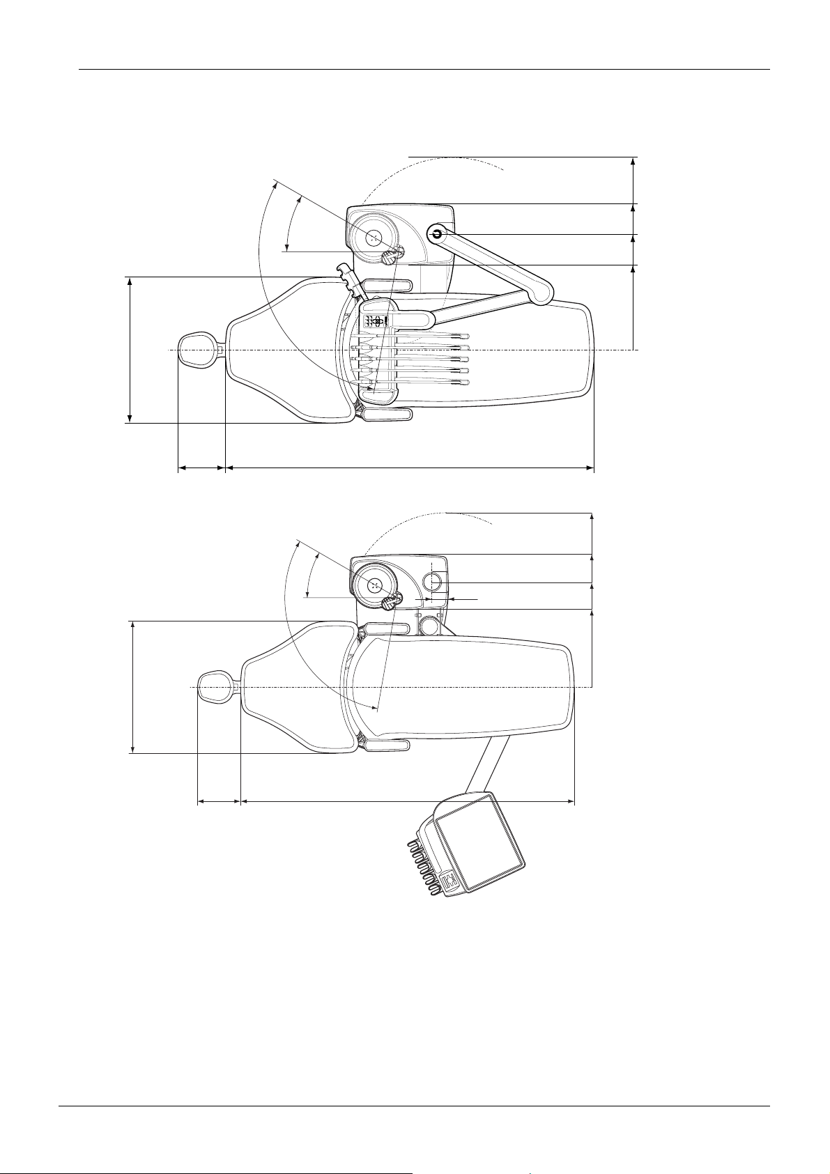
Mechanical dimensions
Installed: (H x D x W) 1210mmx963mmx1990mm (see template for details)
Weight
≈130 kg (287 lbs)
Temperatures and Humidity
Chapter A - GENERAL & TECHNICAL DATA
Operating: +15°C to +35°C, non condensing humidity from 20% to 75%
Storage: 0°C to +50°C, non condensing humidity from 20% to 75%
Mains voltage and frequency
Mains voltage setting Fuse rating & type
100V~ Wickmann no. 195, 12.5 A, slow blow
115V~ Wickmann no. 195, 12.5 A, slow blow
220-240V~ T6.3A, slow blow
Mains frequency 50 or 60 Hz
Power consumption
Idle unit: ≤ 250VA (unit not in use, OP-light turned on)
Typical average: ≈ 350 VA (during patient treatment)
Maximum: ≥ 1200 VA (at maximum rated mains voltage, both chair motors
running)
Electrical classification
Class I, type B
Chair lift- and backrest motors’ operation:
Technical Manual
Intermittent operation, ED 8%, 25 sec "ON", 300 sec. "OFF"
Water supply
Pressure range: min. 300kPa (45 psi), max. 900 kPa (130 psi)
Flow rate: ≤ 4 l/ min (maximum consumption at any instance)
Quality: hardness; ≤ 8 °dH (1°dH= 20mg Ca/ 3 liter water)
Connection: 1/4”
Planmeca Compact i A-3
Page 12

Chapter A - GENERAL & TECHNICAL DATA
Air supply
Pressure range: min. 550 kPa (80 psi), max. 900 kPa (130 psi)
Flow rate: ≥ 55 litres / minute (maximum consumption at any instance)
Air quality: medical grade, dry and oil-free
Connection: 1/4”
Suction connection
Vacuum: ≥ 150 mbar
Flow rate: ≥ 550 l/ min
Connection: 25 mm (3/4”)
Drain connection
Capacity: min. 10 l/min
Connection: 25 mm (3/4”)
TECHNICAL SPECIFICATIONS
A-4 Planmeca Compact i
Technical Manual
Page 13
TECHNICAL SPECIFICATIONS
Dimensions
Chapter A - GENERAL & TECHNICAL DATA
OP delivery arm
(swing of cuspidor) 110˚
640mm (25.2") (Backrest 584)
680mm (26.8") (Backrest 664)
max.
390mm
(15.4")
Side delivery arm
(swing of cuspidor) 110˚
30˚
1620mm (63.8") (fixed seat 610)
1520mm (60") (automatic seat 510)
1470mm (57.9") (automatic seat 460)
30˚
850mm (33.5") (swing
of service door)
645mm (25.4")
510mm (20.1")
375mm (14.8")
0
850mm (33.5") (swing of service door)
645mm (25.4")
80
510mm (20.1")
375mm (14.8")
640mm (25.2") (Backrest 584)
680mm (26.8") (Backrest 664)
max.
390mm
(15.4")
1620mm (63.8") (fixed seat 610)
1520mm (60") (automatic seat 510)
1470mm (57.9") (automatic seat 460)
0
Technical Manual
Planmeca Compact i A-5
Page 14

Chapter A - GENERAL & TECHNICAL DATA
LIST OF TERMS AND ABBREVIATIONS IN THIS MAN-
4 LIST OF TERMS AND ABBREVIATIONS IN THIS
MANUAL
Some frequently used names and parts are abbreviated. The following is a list of the used
abbreviations and their brief explanations.
CPU Central Processing Unit, the microprocessor chip that executes the
software program.
ECB Electronics Control Box. The black-anodized box inside the unit that
contains the MCB and other electrical parts.
EEPROM Electrically Erasable Programmable Read Only Memory.
EPROM Electrically Programmable Read Only Memory.
Flash-EPROM EPROM that can be reprogrammed in the socket without the need
to remove the chip from the PCB.
IMUX Instrument MUltipleXer. The device in the console that selects
and feeds the instruments with power and pressures. Consists of
the valve block cluster and two PCB’s.
IPS Instrument Power Supply (Universal Power Supply located on the
MCB, feeding micromotors, polymerization light bulbs and the
scaler electronics).
kPa kiloPascal, pressure indicator 100kPa = 1bar = 13 PSI
LED Light Emitting Diode, used as indicator lamps and displays.
LCH Light Curing Handpiece (Polymerization light).
MCB Main Control Board. The PCB inside the cuspidor in the “black box”.
This is the “main brain” that controls the whole unit.
na not applicable.
RAM Random Access Memory.
STH Suction Tube Holder.
tba to be announced.
PCB Printed Circuit Board.
PSB Pressure Sensor Board.
PSI Pounds per Square Inch.
QC Quick Connector. The connector at the hose end that connects
to the instrument console IMUX.
A-6 Planmeca Compact i
Technical Manual
Page 15

HANDLING PRECAUTIONS FOR PCB’S AND SOFTWARE
Chapter A - GENERAL & TECHNICAL DATA
5 HANDLING PRECAUTIONS FOR PCB’S AND
SOFTWARE CHIPS
5.1 Handling printed circuit boards
The circuit boards are well protected against static discharges when they are in the unit. However, some precautions are necessary when handling the boards since some internal nodes
can easily be damaged by static electricity.This is true especially during low humidity conditions when there is evidently a potential risk of static discharges.
Keeping these few simple rules in mind when handling PCBs or software chips can make a
big difference;
• Grounding wrist-straps are not necessarily required when handling the boards, as long as
you first always touch a grounded exposed metal part in the unit before touching the PCB.
• Place the removed PCB immediately in an antistatic plastic bag. This protects it from later
improper handling. Please note that PCB’s for warranty replacement must be returned to
the factory properly packaged in antistatic plastic bags.
• Never place a removed PCB on a conductive surface or handle it to another person, without touching the surface or person first.
5.2 Handling software Flash-EPROM chips
To avoid static discharge problems the same rules that apply for PCB’s should be followed
when handling software Flash-EPROM chips.
Software Flash-EPROM chips must be stored in their specific anti-static plastic tubes, protecting them also mechanically.
Since the software chip used is a PLCC-type chip, it must be removed only with a proper
extracting tool (see the spare part manual for details). Using any other tool for removal can
seriously damage the socket on the MCB.
Please refer to 5.1 “How to replace/upgrade the software” on page G-20 for details how to
replace the software.
Technical Manual
Planmeca Compact i A-7
Page 16
Chapter A - GENERAL & TECHNICAL DATA
6 EMC INFORMATION
WARNING
Use of any accessories and cables other than those specified in Planmeca
Compact i dental unit’s documentation, with exception of cables sold by Planmeca as replacement parts for internal components, may result in increased
emission or decreased immunity of the dental unit.
WARNING
Planmeca Compact i dental unit should not be used adjacent to or stacked with
other equipment. If adjacent or stacked use is necessary, the Planmeca Compact i dental unit should be observed to verify normal operation in configuration which it will be used.
EMC INFORMATION
Guidance and manufacturer’s declaration - electromagnetic emissions
Planmeca Compact i dental unit is intended for use in the electromagnetic environment specified
below. The customer or the user of the Planmeca Compact i dental unit should assure that it is
used in such an environment.
Emissions test Compliance Electromagnetic environment – guidance
RF emissions
CISPR 11
RF emissions
CISPR 11
Harmonic emissions
IEC 61000-3-2
Voltage fluctuations/
flicker emissions
IEC 61000-3-3
Group 1
Class B
Class A
Complies
Planmeca Compact i dental unit uses RF energy
only for its internal function. Therefore, its RF
emissions are very low and are not likely to
cause any interference in nearby electronic
equipment.
Planmeca Compact i dental unit is suitable for
use in all establishments, including domestic
establishments and those directly connected to
the public low-voltage power supply network that
supplies buildings used for domestic purposes.
A-8 Planmeca Compact i
Technical Manual
Page 17

EMC INFORMATION
Chapter A - GENERAL & TECHNICAL DATA
Guidance and manufacturer’s declaration - electromagnetic immunity
Planmeca Compact i dental unit is intended for use in the electromagnetic environment specified below.
The customer or the user of Planmeca Compact i dental unit should assure that it is used in such an environment.
Immunity test
Electrostatic
discharge (ESD)
IEC 61000-4-2
Electrical fast
transient/burst
IEC 61000-4-4
Surge
IEC 61000-4-5
Voltage dips, short
interruptions and
voltage variations
on power supply
input lines
IEC 61000-4-11
IEC 60601
test level
±6 kV contact
±8 kV air
±2 kV for power
supply lines
±1 kV for input/output
lines
±1 kV line to line
±2 kV line to earth
U
<5 %
(>95 % dip in
T
U
)
T
for 0,5 cycle
U
40 %
(60 % dip in
T
U
)
T
for 5 cycles
70 %
U
(30 % dip in
T
U
)
T
for 25 cycles
<5 %
U
(>95 % dip in
T
U
)
T
for 5 s
Compliance level
±6 kV contact
±8 kV air
±2 kV for power
supply lines
±1 kV for input/output
lines
±1 kV line to line
±2 kV line to earth
U
<5 %
(>95 % dip in
T
U
)
T
for 0,5 cycle
U
40 %
(60 % dip in
T
U
)
T
for 5 cycles
70 %
U
(30 % dip in
T
U
)
T
for 25 cycles
<5 %
U
(>95 % dip in
T
U
)
T
for 5 s
Electromagnetic environment-
guidance
Floors should be wood, concrete
or ceramic tile. If floors are covered with synthetic material, the
relative humidity should be at
least 30%.
Mains power quality should be
that of a typical commercial or
hospital environment
Mains power quality should be
that of a typical commercial or
hospital environment.
Mains power quality should be
that of a typical commercial or
hospital environment. If the user
of Planmeca Compact i dental
unit requires continued operation
during power mains interruptions,
it is recommended that Planmeca
Compact i dental unit be powered
from an uninterruptible power
supply.
Power frequency(
50/60 Hz)
magnetic field
IEC 61000-4-8
NOTE
Technical Manual
3 A/m 3 A/m
U
is the a.c. mains voltage prior to application of the test level.
T
Power frequency magnetic fields
should be at levels characteristic
of a typical location in a typical
commercial or hospital environment. The power frequency magnetic field should be measured in
the intended installation location
to assure that it is sufficiently low.
Planmeca Compact i A-9
Page 18
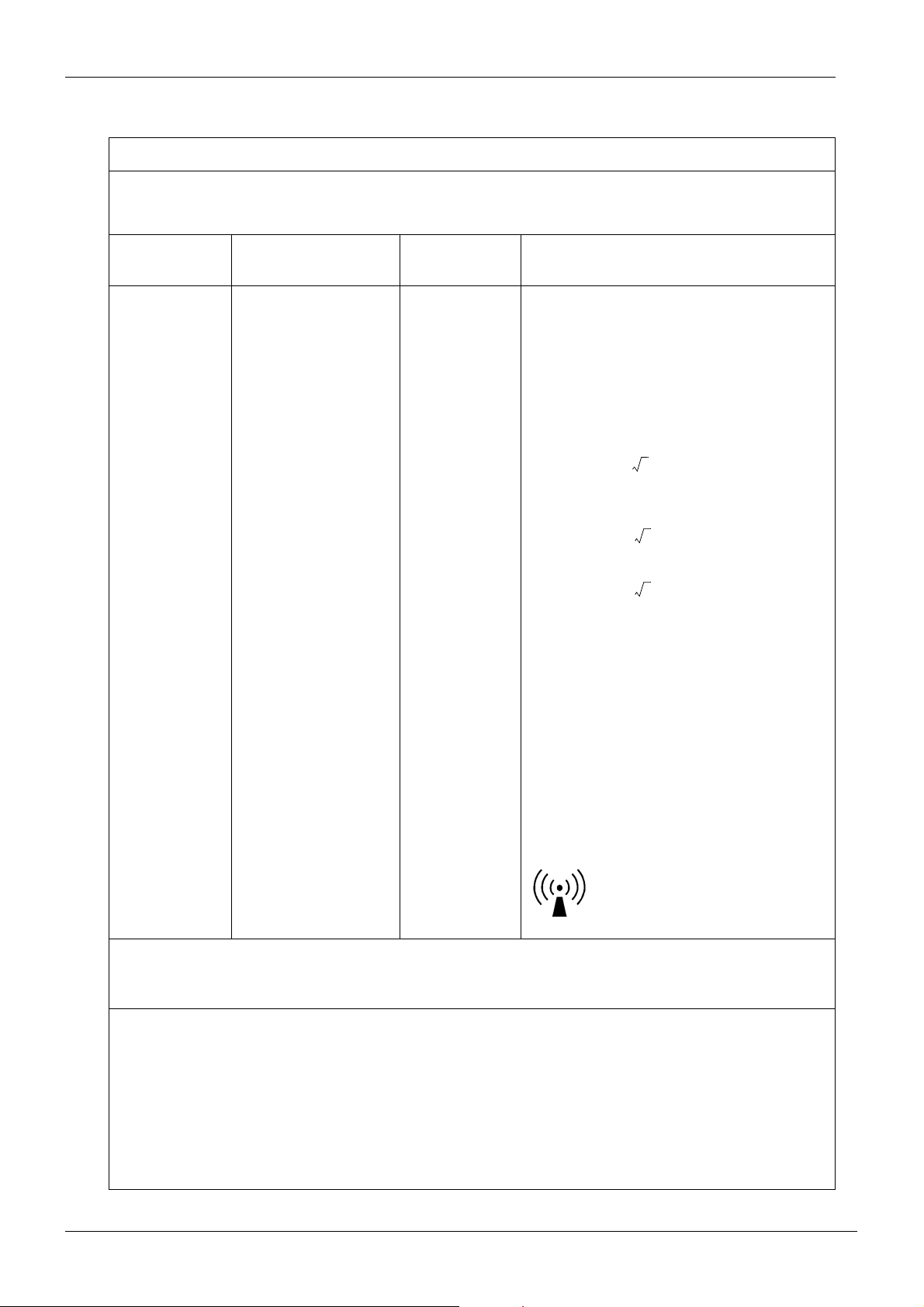
Chapter A - GENERAL & TECHNICAL DATA
Guidance and manufacturer’s declaration - electromagnetic immunity
Planmeca Compact i dental unit is intended for use in the electromagnetic environment specified below.
The customer or the user of Planmeca Compact i dental unit should assure that it is used in such an
environment.
EMC INFORMATION
Immunity test
Conducted RF
IEC 61000-4-6
Radiated RF
IEC 61000-4-3
IEC 60601
test level
3 Vrms
150 kHz to 80 MHz
3 V/m
80 MHz to 2.5 GHz
Compliance
level
3 Vrms
3 V/m
Electromagnetic environment-
guidance
Portable and mobile RF communications
equipment should be used no closer to any
part of the Planmeca Compact i dental unit,
including cables, than the recommended
separation distance calculated from the
equation applicable to the frequency of the
transmitter.
Recommended separation distance
d1.2P=
d1.2P= 80 MHz to 800 MHz
d2.3P=
800 MHz to 2.5 GHz
where P is the maximum output power rating of the transmitter in watts (W) according
to the transmitter manufacturer and d is the
recommended separation distance in
metres (m).
Field strengths from fixed RF transmitters,
as determined by an electromagnetic site
a
survey,
level in each frequency range.
should be less than the compliance
b
Interference may occur in the vicinity of
equipment marked with the following symbol:
NOTE 1: At 80 MHz and 800 MHz, the higher frequency range applies.
NOTE 2: These guidelines may not apply in all situations. Electromagnetic propagation is affected by
absorption and reflection from structures, objects and people.
a
Field strengths from fixed transmitters, such as base stations for radio (cellular/cordless)
telephones and land mobile radios, amateur radio, AM and FM radio broadcast and TV broadcast
cannot be predicted theoretically with accuracy. To assess the electromagnetic environment due
to fixed RF transmitters, an electromagnetic site survey should be considered. If the measured
field strength in the location in which Planmeca Compact i dental unit is used exceeds the
applicable RF compliance level above, Planmeca Compact i dental unit should be observed to
verify normal operation. If abnormal performance is observed, additional measures may be
necessary, such as re-orienting or relocating Planmeca Compact i dental unit.
b
Over the frequency range 150 kHz to 80 MHz, field strengths should be less than 3 V/m.
A-10 Planmeca Compact i
Technical Manual
Page 19
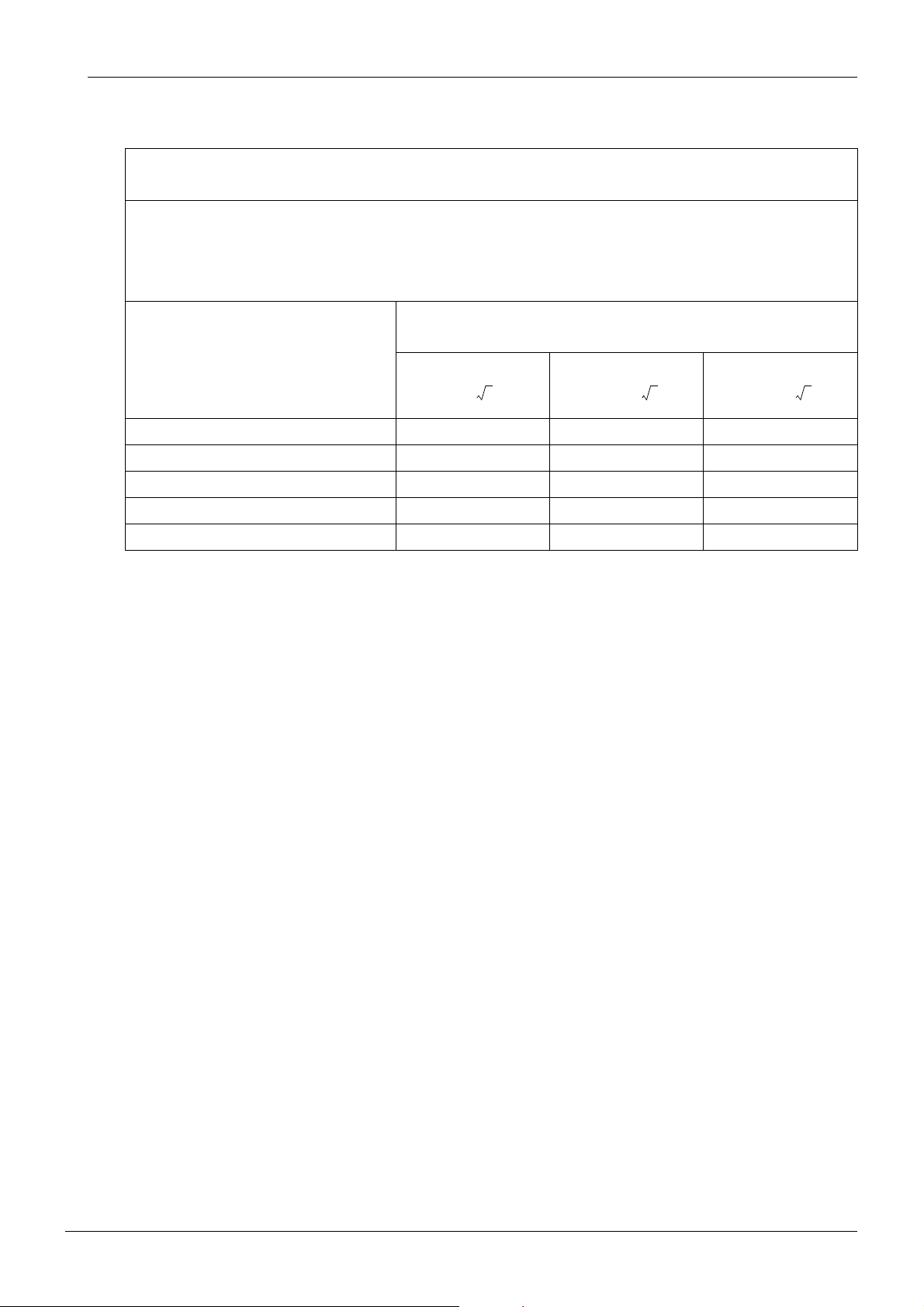
EMC INFORMATION
Chapter A - GENERAL & TECHNICAL DATA
Recommended separation distances between
portable and mobile RF communications equipment and Planmeca Compact i dental unit
Planmeca Compact i dental unit is intended for use in an electromagnetic environment in which radiated
RF disturbances are controlled. The customer or the user of Planmeca Compact i dental unit can help
prevent electromagnetic interference by maintaining a minimum distance between portable and mobile
RF communications equipment (transmitters) and the Planmeca Compact i dental unit as recommended
below, according to the maximum output power of the communications equipment.
Rated maximum output power
of transmitter
W
0.01 0.2 0.2 0.3
0.1 0.4 0.4 0.7
1 1.2 1.2 2.4
10 4.0 4.0 8.0
100 12.0 12.0 24.0
Separation distance according to frequency of transmitter
m
150 kHz to 80 MHz 80 MHz to 800 MHz 800 MHz to 2.5 GHz
d1.2P= d1.2P= d2.3P=
Technical Manual
Planmeca Compact i A-11
Page 20

Chapter A - GENERAL & TECHNICAL DATA
EMC INFORMATION
A-12 Planmeca Compact i
Technical Manual
Page 21
Chapter
B
CONTROL PANEL FUNCTIONS
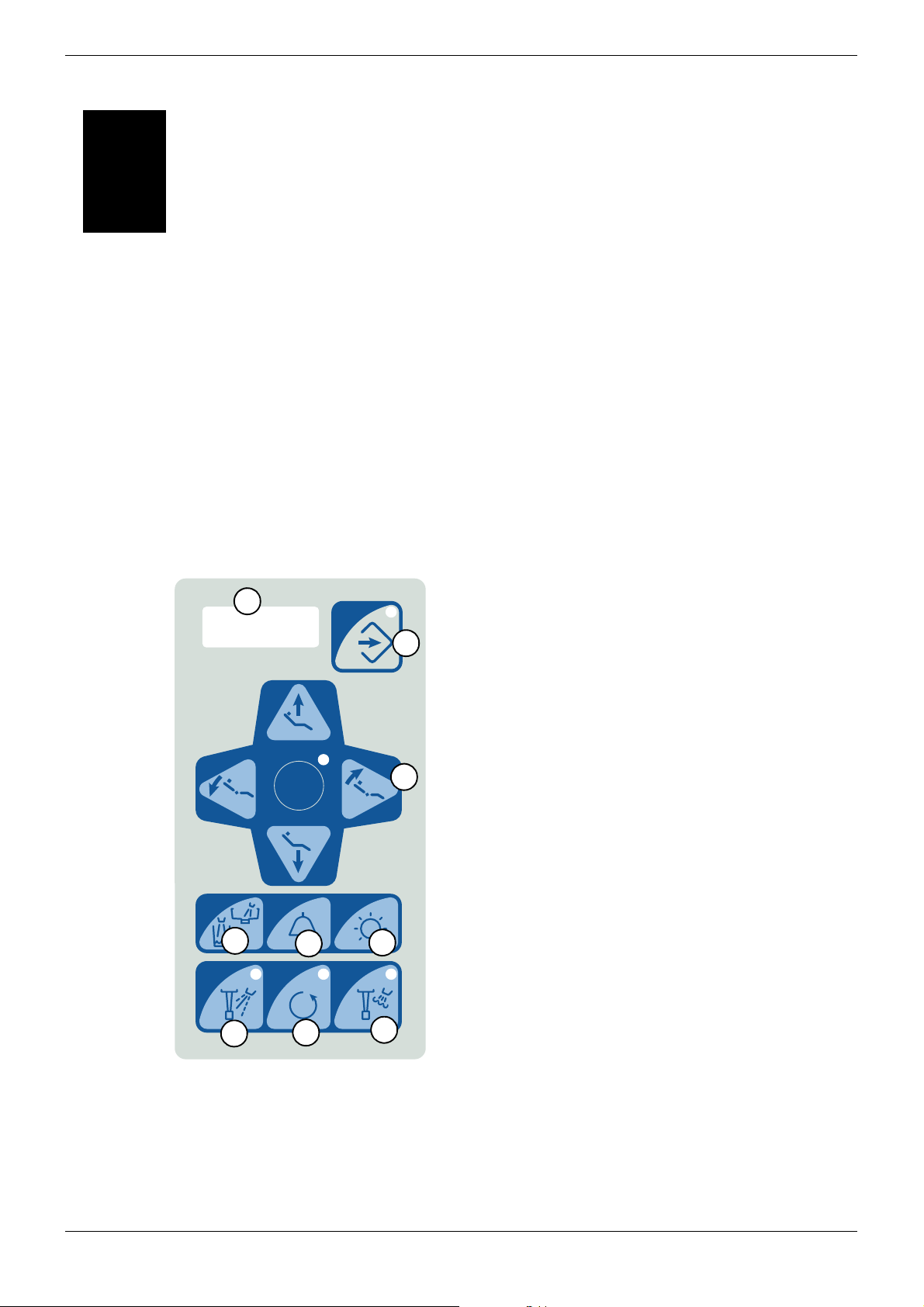
1 CONTROL PANEL OVERVIEW
NOTE For units equipped with the Plus package refer to the Planmeca Compact i
User’s Manual.
This chapter describes the control panel functions in normal and service modes. There are
some special control and display modes that are not normally available but which can be
entered by certain key sequences. In the following it is explained what operations can be
achieved with the keys and which indications appear on the display.
(1) Multi-purpose Display;
“PCI” -text displayed when unit is idle
1
2
C
- instrument speed or power
- polymerization light curing time
- help and error messages
- instrument settings in program mode
- other unit settings in program mode
- service mode information
A
(2) Program mode key and indicator light
(3) Patient chair control keys;
A - backrest down / go to position A
B - backrest up / go to position B
C - seat up / go to position C
D - seat down / go to position D
S - run to / return from spittoon position
S
3
B
D
(4) Bowl rinse/glass fill key
(5) Extra function key (door open / nurse call etc.)
4
7
5
8
6
9
(6) Operating light control key
(7) Instrument spray key and indicator light
(8) Micromotor reverse key and indicator light
(9) Automatic chip-blow key and indicator light
Technical Manual
Planmeca Compact i B-1
Page 22
Chapter B - CONTROL PANEL FUNCTIONS
2 NORMAL USER FUNCTIONS
The control panel is always in the normal operating mode when the unit is switched on.
Please refer to the Planmeca Compact i User’s Manual for descriptions for the normal control
panel operation and instructions for normal everyday use of the unit.
3 USER PROGRAMMING MODE
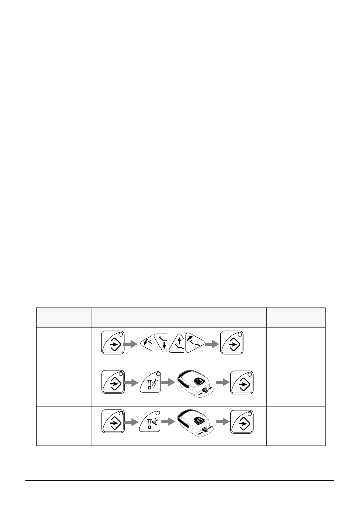
There are several adjustments the user can perform to fulfil individual needs by using the user
programming mode.
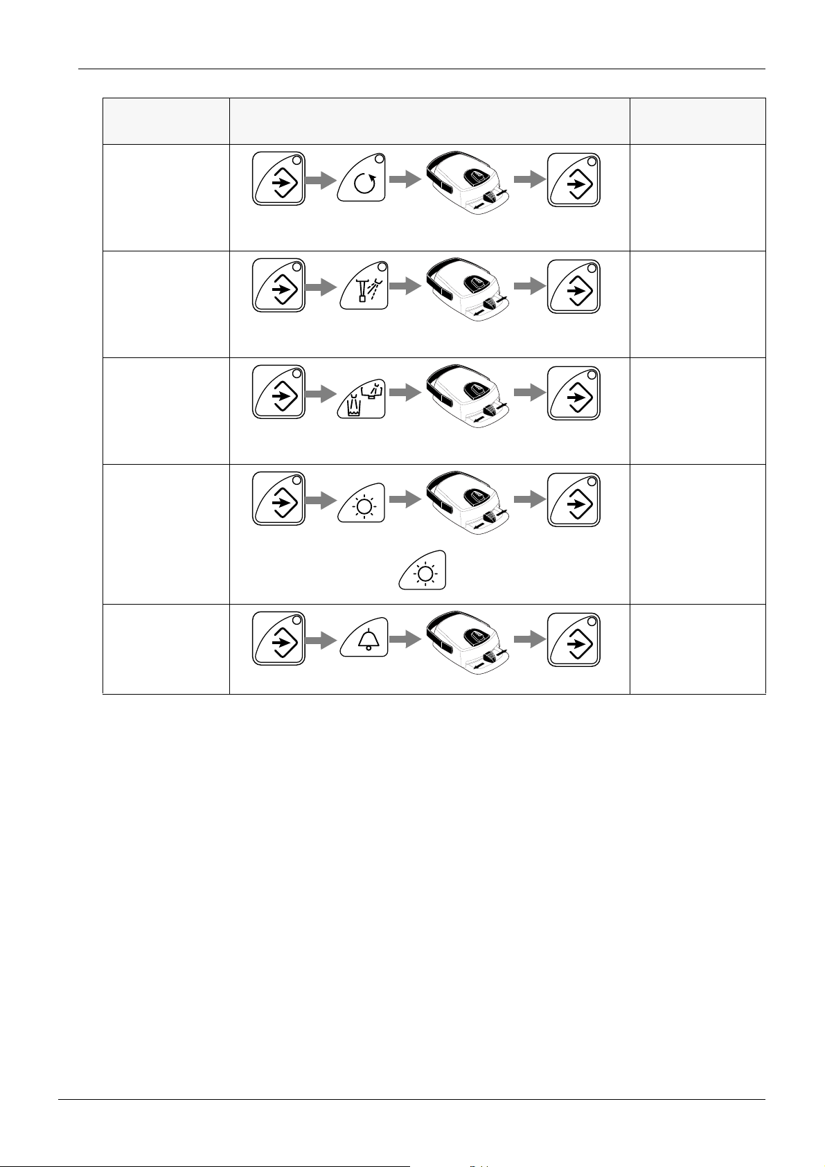
All user programming follows the same pattern:
a) Press the program key to activate the programming mode. The indicator light will come on.
b) Select the desired function from the control panel.
c) Change the setting of the function with the foot control. Push the pedal halfway right to
increase the parameter value and halfway left to decrease it. If the pedal is pushed more than
0.4 sec., the value will change as long as the pedal is pushed.
d) Press the program key to store the new setting into the memory. The indicator light will go out.
e) When programming instrument settings; remove the instrument that you wish to program
from its holder. After identifying the instrument it can be either held out from or returned to its
holder. If returned you have 3 seconds time to enter the programming mode.
NORMAL USER FUNCTIONS
NOTE The maximum air and water flow rate of the syringe can not be changed via the
keyboard controls. However, there are screwdriver-adjustable valves inside the
console that can be adjusted if desired. Please refer to 3.2 “Adjusting syringe
water and air flow rates” on page F-27.
FUNCTION KEY SEQUENCE
Programming
chair automatic
positions
Adjusting spray
water and air flow
on selected instrument
Adjusting chip
blow air and water
flow on selected
instrument
A
C
D
B
FOR DETAILS
REFER TO
4.1 “Automatic chair
positions” on page
B-4
4.2 “Instrument
spray flow rates” on
page B-4
4.3 “Chip blow flow
rates” on page B-5
B-2 Planmeca Compact i
Technical Manual
Page 23
USER PROGRAMMING MODE
Chapter B - CONTROL PANEL FUNCTIONS
FUNCTION KEY SEQUENCE
Adjusting fibre
light intensity on
selected instrument
Selecting exposure time on
selected polymerization light
Adjusting bowl
rinse and glass fill
times
Adjusting operating light intensity
FOR DETAILS
REFER TO
4.4 “Fibre optic light
intensity” on page
B-6
4.5 “Polymerization
light exposure time”
on page B-6
4.6 “Duration of the
bowl rinsing and
duration of the glass
filling” on page B-7
4.7 “Intensity of the
operating light” on
page B-8
Adjusting extra
function (door/
nurse) signal duration
Alternative method: press and hold
4.8 “Duration of the
extra function relay
activation” on page
B-8
Technical Manual
Planmeca Compact i B-3
Page 24
Chapter B - CONTROL PANEL FUNCTIONS
PROGRAMMING MODE FUNCTION DETAILS
4 PROGRAMMING MODE FUNCTION DETAILS
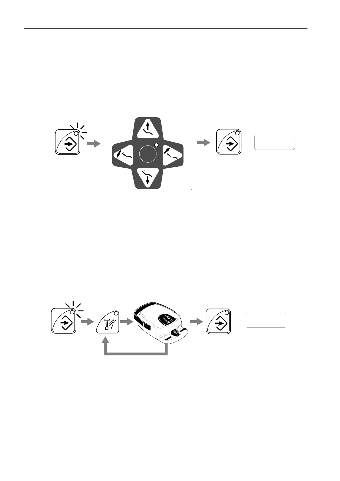
4.1 Automatic chair positions
The chair must be in the desired position to be programmed before entering the programming
mode. If not, please first move the chair to the position required using the chair foot control or
the chair keys on the unit control panel.
C
PoS.A
A
S
B
D
a) Press the program key.
b) Press the desired chair position key where to store the chair’s position (S, A, B, C or D).
Switch the operating light on or off for this position. Note that if you are programming the
spittoon position, you can not select the operating light setting.
c) The text ‘PoS.n’ will appear on the display (n can then be either A, b, C, d or S).
d) Press the program key to store the chair position into the memory. The indicator light will go
out.
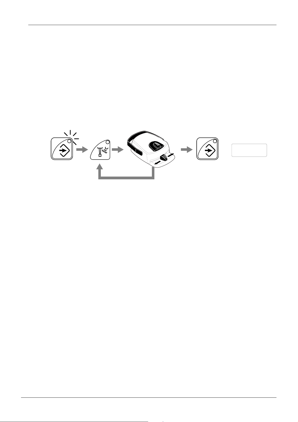
4.2 Instrument spray flow rates
Since the adjustment is individual for each instrument, you must indicate which instrument to
program by picking it out from the holder.
-
+
SA.35
a) Press the program key.
b) Press the instrument spray key. The text ‘SA.nn’ or ‘SH.nn’ will appear on the display
indicating which of the parameters will be adjusted (A for air and H for water).
c) Press the spray key repeatedly (or the foot control pedal briefly down) to toggle between air
and water adjustment.
d) Change the flow rate with the help of the foot control pedal. Bringing the pedal to the right will
increase the flow, taking it to the left side will decrease the flow. Please note that the
instrument will run normally during this operation. Turbines will start immediately to full speed.
e) Press the program key to exit and store the new spray settings.
B-4 Planmeca Compact i
Technical Manual
Page 25
PROGRAMMING MODE FUNCTION DETAILS
Chapter B - CONTROL PANEL FUNCTIONS
NOTE If the dental unit is equipped with the Planmeca Sterile Water System, the ster-
ile water function is selected in this mode. Letters ‘St’ indicate that sterilized
water is fed to the selected instrument. The indicator light of the instrument
spray key flashes when the spray is on. For more information, refer to the Sterile Water System User’s Manual.
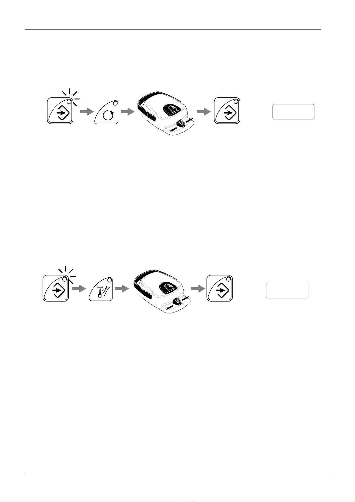
4.3 Chip blow flow rates
Since the adjustment is individual for each instrument, you must indicate which instrument to
program by picking it out from the holder.
+
CA.nn
-
a) Press the program key.
b) Press the chip blow key. The text ‘CA.nn’ or ‘CH.nn’ will appear on the display indicating
which of the parameters will be adjusted (A for air and H for water). The factory setting is full
air pressure and water off.
c) Press the chip blow key repeatedly (or the foot control pedal briefly down) to toggle between
air and water adjustment.
d) Change the flow rate with the help of the foot control pedal. Bringing the pedal to the right will
increase the flow, taking it to the left side will decrease the flow. Please note that the
instrument will not run during this programming operation.
e) Press the program key to exit and store the new automatic chip blow settings.
NOTE The manual chip blow is set as default to be dry (air only), independent of the
automatic chip blow programming. However, if desired, this can be altered,
please refer to “n.43 Set mode of foot controlled chip-blow (n range = 0,1, 2)”
on page C-26.
Technical Manual
Planmeca Compact i B-5
Page 26
Chapter B - CONTROL PANEL FUNCTIONS
4.4 Fibre optic light intensity
Since the adjustment is individual for each instrument, you must indicate which instrument to
program by picking it out from the holder. Obviously this mode is valid only for instruments
that can be equipped with a fibre light.
PROGRAMMING MODE FUNCTION DETAILS
+
-
a) Press the program key.
b) Press the reverse rotation key. The text ‘L. nn’ or ‘L. oFF’ will appear on the display.
c) Change the light intensity with the help of the foot control pedal. Bringing the pedal to the right
will increase the light, taking it to the left side will decrease the light. Please note that the
instrument will not run during this programming operation. The light can be programmed to be
always off: after reaching the minimum value the light is switched off, indicated by ‘L.oFF’ on
the display.
d) Press the program key to exit and store the new light intensity into the memory.
4.5 Polymerization light exposure time
Since the adjustment is individual for each curing light, you must indicate which instrument to
program by picking it out from the holder.
L. 90
+
t. 30
-
a) Press the program key.
b) Press the instrument spray key. The text ‘t. nn’ will appear on the display, nn indicates the
current exposure time in seconds.
c) Change the exposure time with the help of the foot control pedal. Bringing the pedal to the
right will increase the time, taking it to the left side will decrease the time. The interval is 5
seconds. Please note that the curing light does not start during the programming.
d) Press the program key to exit and store the new setting.
NOTE The recommended exposure times (factory settings) for various lights are as
follows, and should not be set shorter than indicated to guarantee a good cur-
ing effect;
Demetron 30 seconds
Lysta 40 seconds.
B-6 Planmeca Compact i
Technical Manual
Page 27
PROGRAMMING MODE FUNCTION DETAILS
Chapter B - CONTROL PANEL FUNCTIONS
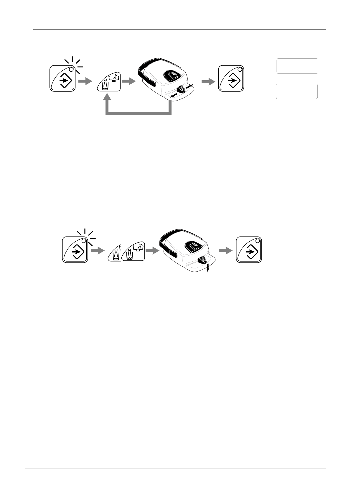
4.6 Duration of the bowl rinsing and duration of the glass filling
b. 30
+
c. 6.0
-
a) Press the program key.
b) Press the bowl rinse/glass fill key. Press it repeatedly to toggle between bowl rinsing and cup
filling times. The text ‘b.nnn’ indicates bowl rinse time, the text ‘c.nn.n’ indicates cup filling
time.
c) Change the duration with the help of the foot control pedal. Bringing the pedal to the right
increases the time, taking it to the left side will decrease the time.
d) The minimum value of the bowl rinsing is 5 sec. and the maximum 240 sec., and the
adjustment step is 5 seconds. The minimum value of the glass filling is 2 sec. and the
maximum 10 sec., and the adjustment step is 0.5 seconds.
e) Press the program key.
NOTE The duration of the glass filling can alternatively be programmed as follows:
a) Place an empty glass to the glass holder.
b) Press the program key.
c) Press the bowl rinse/glass fill key twice. The text ‘c.nn.n’ will appear on the display.
d) Push and hold the foot control pedal down. The glass filling time will first be set to 2 seconds
and will start to increase after 2 seconds. The pedal can be released and then pushed again,
and the time continues to increase.
e) Press the program key to exit and store the new setting.
Technical Manual
Planmeca Compact i B-7
Page 28
Chapter B - CONTROL PANEL FUNCTIONS
PROGRAMMING MODE FUNCTION DETAILS
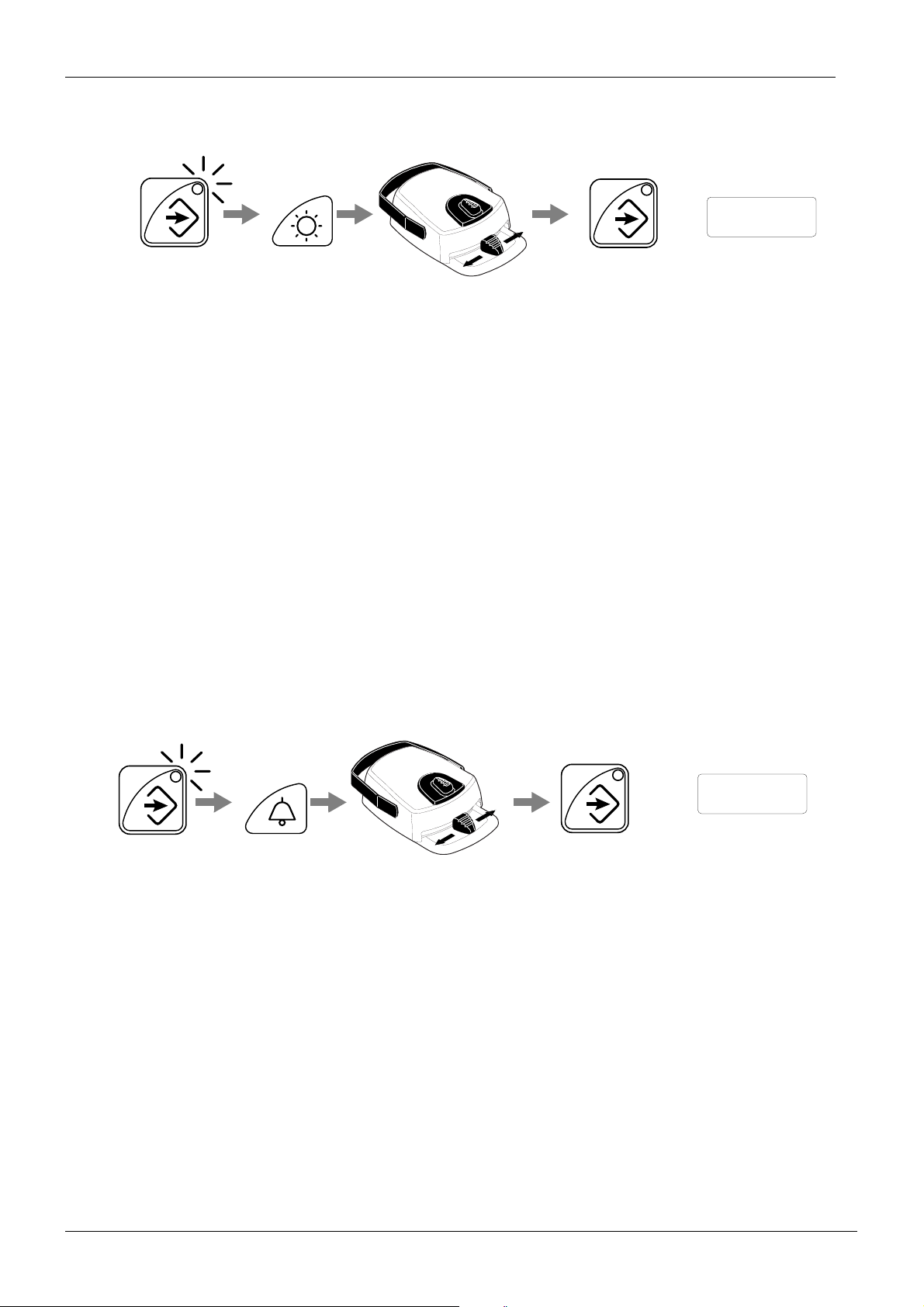
4.7 Intensity of the operating light
+
-
a) Press the program key.
b) Press the operating light key. The text ‘
c) Change the intensity with the help of the foot control pedal. Bringing the pedal to the right
increases the intensity, taking it to the left side will decrease the intensity.
d) The minimum value is 70% of the maximum intensity and the maximum 100%, and the
adjustment step is 2.
e) Press the program key to exit and store the new setting.
NOTE The intensity of the operating light can also be programmed as follows:
o
nnn’ will appear on the display.
o
82
Press and hold the operating light key (or the button in the light handle) for longer than 0,5
seconds. As long as the button is pressed, the light intensity slowly decreases (or increases)
until it comes to the minimum (or maximum) value. A short beep sounds at the end limit. The
adjustment direction is automatically toggled each time the button is released.
Both methods have the same effect when adjusting the brightness of the operating light. How-
ever, the former is implemented only for the sake of symmetry of the functions, the later
method being the easier to use.
4.8 Duration of the extra function relay activation
+
-
a) Press the program key.
b) Press the extra function key. The text ‘d.nnn’ will appear on the display.
c) Change the door open/nurse call time with the foot control. The minimum value is 0 sec. and
the maximum 25 sec., and the adjustment step is 0.5 seconds.
d) Press the program key.
d. 12
B-8 Planmeca Compact i
Technical Manual
Page 29

Chapter
C
CAUTION Some of the service mode functions can be used to alter the operation of the
CAUTION The chair lift mechanism can be driven at any time (even if the service door is
SERVICE MODE
unit. Never use service modes that you are not familiar with how they operate.
open) in the service mode. Make sure to remove tools and fingers from the
mechanism prior to running the chair from its controls.
1 GENERAL ABOUT THE SERVICE MODE
The service mode is intended to assist the technician in the service and setup of the unit:
• display of all internal signals from sensors and switches
• display of internal voltages and other variables
• display of output and control signals
• adjustment of unit’s parameters
• preset of all the parameters to the factory default
The service mode is entered using a special key sequence. The entry has been made difficult
on purpose to prevent accidental entry. The numeric display and the chair control keys
change meaning in the service mode. The rest of the keys and the unit work normally.
NOTE The user display is replaced with service mode information, and no error or
help codes are displayed in the service mode.
NOTE Even if listed in this documentation, some service modes are reserved for
future use and might not yet be implemented in the current software version.
Technical Manual
Planmeca Compact i C-1
Page 30
Chapter C - SERVICE MODE
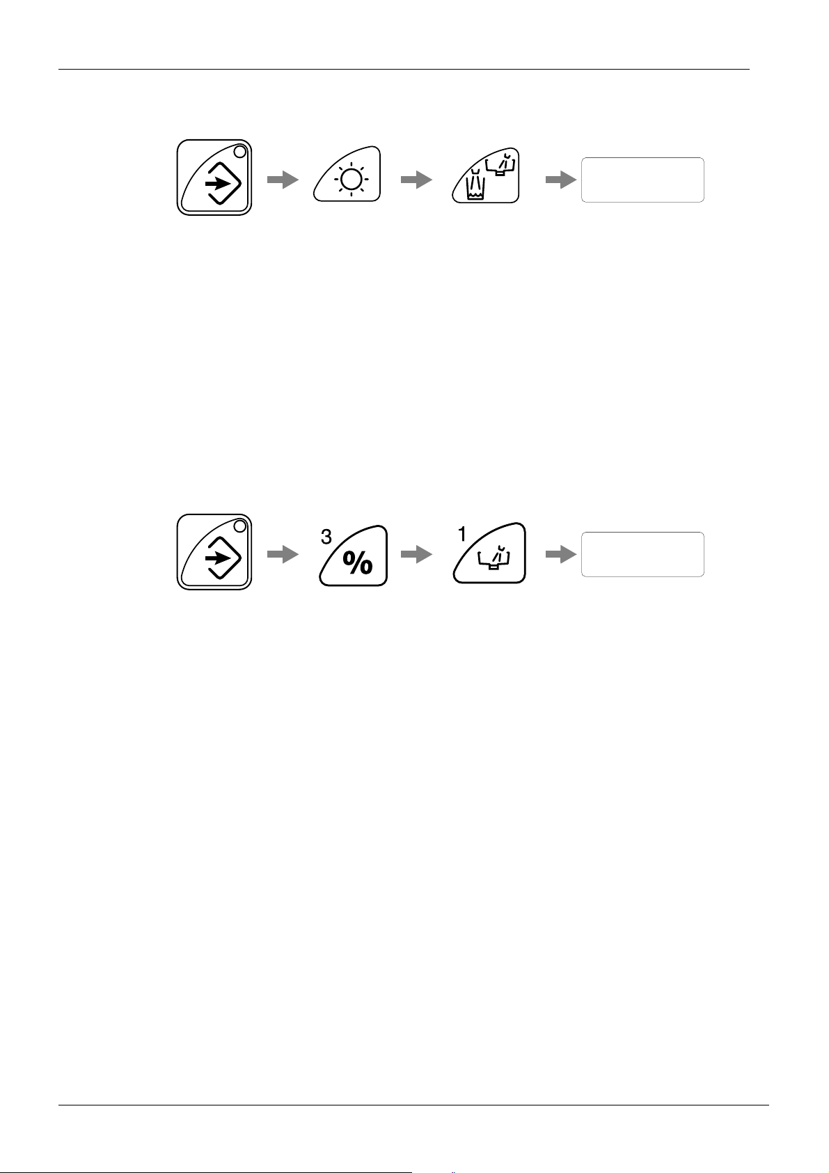
1.1 How to enter service mode
GENERAL ABOUT THE SERVICE MODE
SEr
PROGRAM KEY
Press and hold
continuously
a) Press the program key and hold it down.
b) Press the operating light key until you hear a beep (approx. 2 seconds).
c) Then press the bowl rinse/glass fill key until you hear a beep (approx. 2 seconds).
d) Release both keys (program key & bowl rinse/glass fill key). The display briefly shows “SEr”
when service mode is entered.
The number of the latest used service mode will then be shown on the display. After 1 second
it will be replaced with the current setting or value of this service mode.
Press and hold
until you hear a beep
Press and hold
until you hear a beep
Release keys
Units equipped with Plus package:
SEr
PROGRAM KEY
Press and hold
continuously
Press and hold
until you hear a beep
Press and hold
until you hear a beep
Release keys
a) Press the program key and hold it down.
b) Press the instrument power reduction key until you hear a beep (approx. 2 seconds).
c) Then press the bowl rinse key until you hear a beep (approx. 2 seconds).
d) Release both keys (program key & bowl rinse key). The display briefly shows “SEr” when
service mode is entered.
The number of the latest used service mode will then be shown on the display. After 1 second
it will be replaced with the current setting or value of this service mode.
NOTE If the unit is equipped with the Dürr amalgam separating system or Dürr VSA
system, holding the program key down for 4 seconds (without additionally
pressing any other keys) will automatically start the suction system flushing
function.
1.2 How to exit service mode and store settings
Briefly press the program key.
C-2 Planmeca Compact i
Technical Manual
Page 31
GENERAL ABOUT THE SERVICE MODE
Chapter C - SERVICE MODE
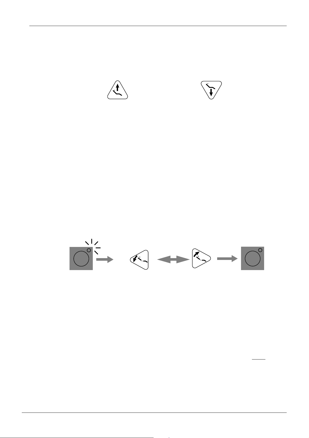
1.3 Navigating among the various service modes
The service modes are numbered with consecutive numbers. To move to the required service
mode, use the chair up and down keys (“C” or “D”) on the control panel. All the patient chair
control keys are now used for controlling the service mode and do not control the chair.
C
D
Press to move up in the list Press to move down in the list
The current service mode number (symbol “n” followed by the current service mode number)
is shown on the display when moving around in the list.
Due to the small display, there are not enough digits to show simultaneously the service
mode number and its contents. Therefore the service mode number disappears after 1 second, after which the current service mode setting or value is displayed.
Checking the current service mode number
When the service mode setting is shown on the display, pressing briefly either of the moving
keys (“C” or “D”) brings momentarily the number of the current service mode to the display.
The unit does not move to the next (or previous) service mode.
1.4 Changing an adjustable setting in the service mode
Some of the service mode numbers display a decimal point after the symbol “n”. These
modes have settings that can be changed. To change a setting do as follows:
A
S
Press and hold until LED lights
to enter the SET mode
a) Move to the desired service mode as described in 1.3 “Navigating among the various service
modes”.
b) Enter the SET-mode by pressing and holding the “S”-key until the yellow indicator light turns
on (1 or 5 seconds, depending on the service mode).
c) Decrease the setting with the “A”-key, or increase it with the “B”-key.
d) Exit the SET-mode by briefly pressing the S-key (the indicator light turns off). The SET-mode
is exited automatically if you scroll to a different service mode using the “C” and “D” keys.
However, any changes made to the previous service mode are stored.
Decrease the setting
B
Increase the setting
S
Exit SET mode
NOTE To ensure that changes made in the service mode are stored, you must exit the
Technical Manual
service mode by using the program key. All altered settings, even if they have
an immediate effect, are lost if the power is turned off before pressing the pro-
gram key.
This behaviour can, however, be used as a “master undo”, if you for some rea-
son want to return to the previous settings. The factory presets (mode 16) are
stored immediately and cannot be un-done.
Planmeca Compact i C-3
Page 32
Chapter C - SERVICE MODE
GENERAL ABOUT THE SERVICE MODE
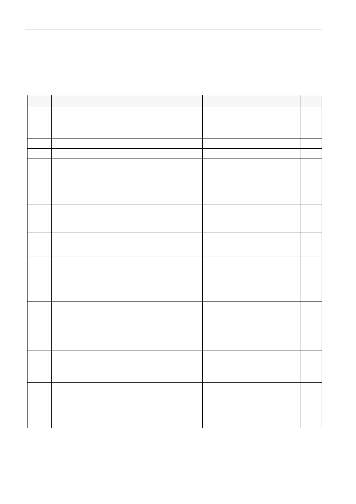
1.5 Service mode functions short-form
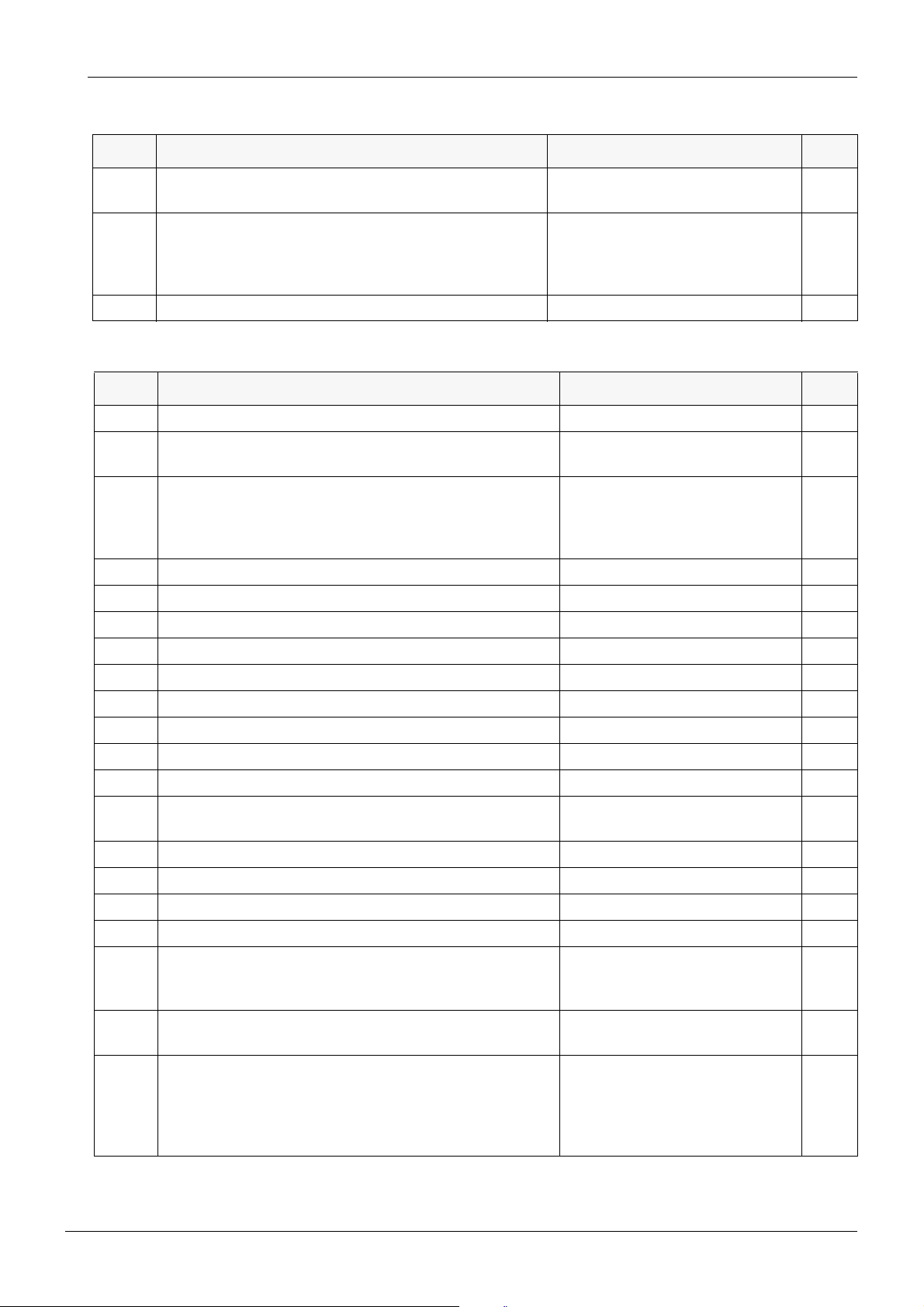
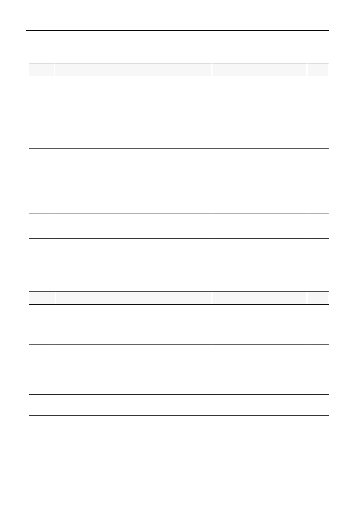
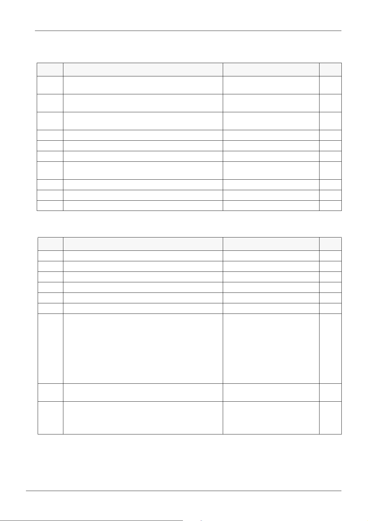
The following pages list all available service modes as short-form tables. For detailed descriptions of the service modes, please refer to pages indicated in the right column.
The service modes are grouped according to functions into individual tables.
Table 1: MAIN control system related service modes
MODE SERVICE MODE FUNCTION DISPLAY/RANGE page
n.0 Disable programming and limit micromotor speed 0 - 15 (default = 0) C-17
n 1 Show software version on MCB n.nn.n C-18
n 2 Show internal unregulated operating voltage 33.0VDC (±15%), 28.0...38.0 VDC C-18
n 3 Show output current of IPS 0.00 - 7.00 A C-18
n 4 Show output voltage of IPS 00.0 - 33.0 VDC C-18
n 5 Show scaler electronics ID-code 0 = no scaler electronics installed
1 = Amdent
2 = EMS
3 = Satelec
6 = Newtron
4, 5, 7 = reserved
n 6 Show service door switch signal 0 = door closed
1 = door open
n 7 Show mains frequency nn.n Hz (cycles/second) C-19
n 8 Show (optional) assistant syringe hose ID - = no hose connected
0 = not a syringe
nn = syringe ID code
n 9 Show (optional) assistant syringe hose sense signal 0 - 255 C-19
n 10 Show MCB heatsink temperature nn °C (or °F) C-19
n.11 Enable (optional) water heater 1 = enabled (heating on)
- = enabling (10 second delay)
0 = disabled (no heating, default)
n.12 Set main air valve operation 1 = always on
A = automatic (default)
0 = always off
n.13 Set main water valve operation 1 = always on
A = automatic (default)
0 = always off
C-19
C-19
C-19
C-20
C-20
C-20
n.14 Disable automatic functions in S-position 0 = no water to cup or cuspidor
1 = flush cuspidor only
2 = fill cup only
3 = fill cup, flush bowl (default)
n.15 Disable error messages 0 = no error messages are dis-
played
1 = error messages will show
(default)
2 = error messages relating con-
sole arm are not displayed
C-4 Planmeca Compact i
C-20
C-20
Technical Manual
Page 33
GENERAL ABOUT THE SERVICE MODE
Chapter C - SERVICE MODE
Table 1: MAIN control system related service modes
MODE SERVICE MODE FUNCTION DISPLAY/RANGE page
n.16 Enable factory preset mode A = perform service mode preset
C-21
B = perform user mode preset
n.17 Select display units for pressures and temperature 1 = bar (n.nn) and Celsius (default)
C-21
2 = kPa (nnn) and Celsius
3 = PSI (nn.n) and Fahrenheit
4 = PSI (nn.n) and Celsius
n.18 Factory test - C-21
Table 2: Instrument MUX related service modes
MODE SERVICE MODE FUNCTION DISPLAY/RANGE page
n 19 Show software version of IMUX CPU n.nn C-22
n 20 Show instrument holder & AUX-input signals ¦ ¦¦¦¦¦; long =active (on), short =in
C-22
holder (off)
n 21 Show active instrument hose ID-code ---- = no active instrument
C-22
selected
nn = ID code
0 = no hose connected
n 22 Show active instrument hose identification signal 0 - 255 C-22
n 23 Show active instrument switch/sensor signal 0 - 255 C-22
n 24 Show console syringe location hose ID-code 0 = no hose, nn = ID code C-22
n 25 Show console syringe location hose identification signal 0 - 255 C-23
n 26 Show console syringe switch signal 0 - 255 C-23
n 27 Show IMUX on/off valve signals ¦¦¦¦¦¦ (long = on, short = off) C-23
n 28 Show IMUX other output signals ¦¦¦¦¦¦ (long = on, short = off) C-23
n 29 Show air / water pressure difference (±) n.nn bar; nnn kPa; nn.n PSI C-23
n 30 Show active instrument drive/cooling air pressure n.nn bar; nnn kPa; nn.n PSI C-23
n.31 Select the service mode navigation type 0 = normal
C-24
2 = accelerated (default)
n 32 Show active instrument spray air pressure n.nn bar; nnn kPa; nn.n PSI C-24
n.33 Factory test C-24
n 34 Show active instrument spray water pressure n.nn bar; nnn kPa; nn.n PSI C-24
n.35 Factory test C-24
n.36 Set mode of IMUX membrane operation 1 = continuously on when unit is
C-24
idle (default)
0 = off when unit is idle
n.37 Disable turbine contamination prevention system 1 = enabled (factory default)
C-25
0 = disabled
n 38 Show internal water or air pressure A (A) = show internal air pressure
C-25
H (B) = show internal water pressure
X n.nn bar; X nnn kPa; X nn.n
PSI
Technical Manual
Planmeca Compact i C-5
Page 34
Chapter C - SERVICE MODE
GENERAL ABOUT THE SERVICE MODE
Table 3: Instrument related service modes
MODE SERVICE MODE FUNCTION DISPLAY/RANGE page
n.39 Set maximum fibre optic and Intracam bulb voltage for
selected hose type
---- = no valid hose selected
0 = factory default (nominal voltage)
< 0 = decrease max. voltage
> 0 = increase max. voltage
n.40 Fine-adjust bulb voltage for selected polymerization light ---- = no valid light selected
0 = factory default
> 0 = increase voltage
< 0 = decrease voltage
n.41 Set fibre optic light turn-off delay for all instruments nn = seconds; factory default =
30 s.
n.42 Fine-adjust cooling air pressure for selected hose type ---- = no valid hose selected
0 = factory default
< 0 = decrease cooling air pressure
> 0 = increase cooling air pressure
n.43 Set mode of foot controlled chip-blow 0 = as auto-chip is programmed
1 = always dry (factory default)
2 = no chip blow
n.44 Fine-adjust drive air pressure for selected hose type ---- = no valid hose selected
0 = factory default
< 0 = decrease drive pressure
> 0 = increase pressure
C-26
C-26
C-26
C-26
C-26
C-26
Table 4: Control panel related service modes
MODE SERVICE MODE FUNCTION DISPLAY/RANGE page
n 45 Show control panel type/AUX input for branch 1 - = no panel found
C-27
0 = nurse’s plus panel
1 = doctor’s panel
2 = nurse’s panel
3 = doctor’s plus panel
n 46 Show control panel type/AUX input for branch 2 - = no panel found
C-27
0 = nurse’s plus panel
1 = doctor’s panel
2 = nurse’s panel
3 = doctor’s plus panel
n 47 Show control panel key code for branch 1 n.- = row, -.n = column C-27
n 48 Show control panel key code for branch 2 n.- = row, -.n = column C-27
n 49 Display test All LEDs turn on C-27
C-6 Planmeca Compact i
Technical Manual
Page 35
GENERAL ABOUT THE SERVICE MODE
Chapter C - SERVICE MODE
Table 5: Suction holder related service modes
MODE SERVICE MODE FUNCTION DISPLAY/RANGE page
n 50 Show suction holder type and status for branch 1 n.¦¦¦¦; n=type, long= active, short
=
in holder
n 51 Show suction holder type and status for branch 2 n.¦¦¦¦; n=type, long= active, short
=
in holder
n 52 Show left (high volume) suction sensor signal for branch 10 - 255 C-28
n 53 Show middle (saliva) suction sensor signal for branch 1 0 - 255 C-28
n 54 Show right (ejector) suction sensor signal for branch 1 0 - 255 C-28
n 55 Show AUX input signal for branch 1 0 - 255 C-28
n 56 Show left (high volume) suction sensor signal for branch 20 - 255 C-29
n 57 Show middle (saliva) suction sensor signal for branch 2 0 - 255 C-29
n 58 Show right (ejector) suction sensor signal for branch 2 0 - 255 C-29
n 59 Show AUX input signal for branch 2 0 - 255 C-29
C-28
C-28
Table 6: Foot control related service modes
MODE SERVICE MODE FUNCTION DISPLAY/RANGE page
n 60 Show software version in Foot Control CPU n.nn C-29
n 61 Show foot control switch signals ¦¦ ¦ ¦¦¦¦; JA, JB, AUX, A, B, C, D C-29
n 62 Show pedal horizontal position coordinate ±255 (horizontal centre = 0) C-30
n 63 Show pedal vertical position coordinate ±100 (vertical midway = 0) C-30
n 64 Show left side sensor signal (unprocessed) nnnn C-30
n 65 Show right side sensor signal (unprocessed) nnnn C-30
n.66 Select foot control pedal operation mode 0 = normal (default)
C-30
1 = instrument control with vertical movement
2 = reversing of micromotor rotation is done with foot control
3 = reversing of micromotor rotation is done with foot control
4 = power limitation selection
done with foot control
n.67 Disable foot control pedal extra functions 1 = normal (all features, default)
C-31
0 = no extra functions
n.68 Disable automatic chair positions (A, B, C, D) from foot
control
0 = manual control on, automatic
positions off
C-31
1 = normal (all features, default)
2 = both chair controls off
Technical Manual
Planmeca Compact i C-7
Page 36
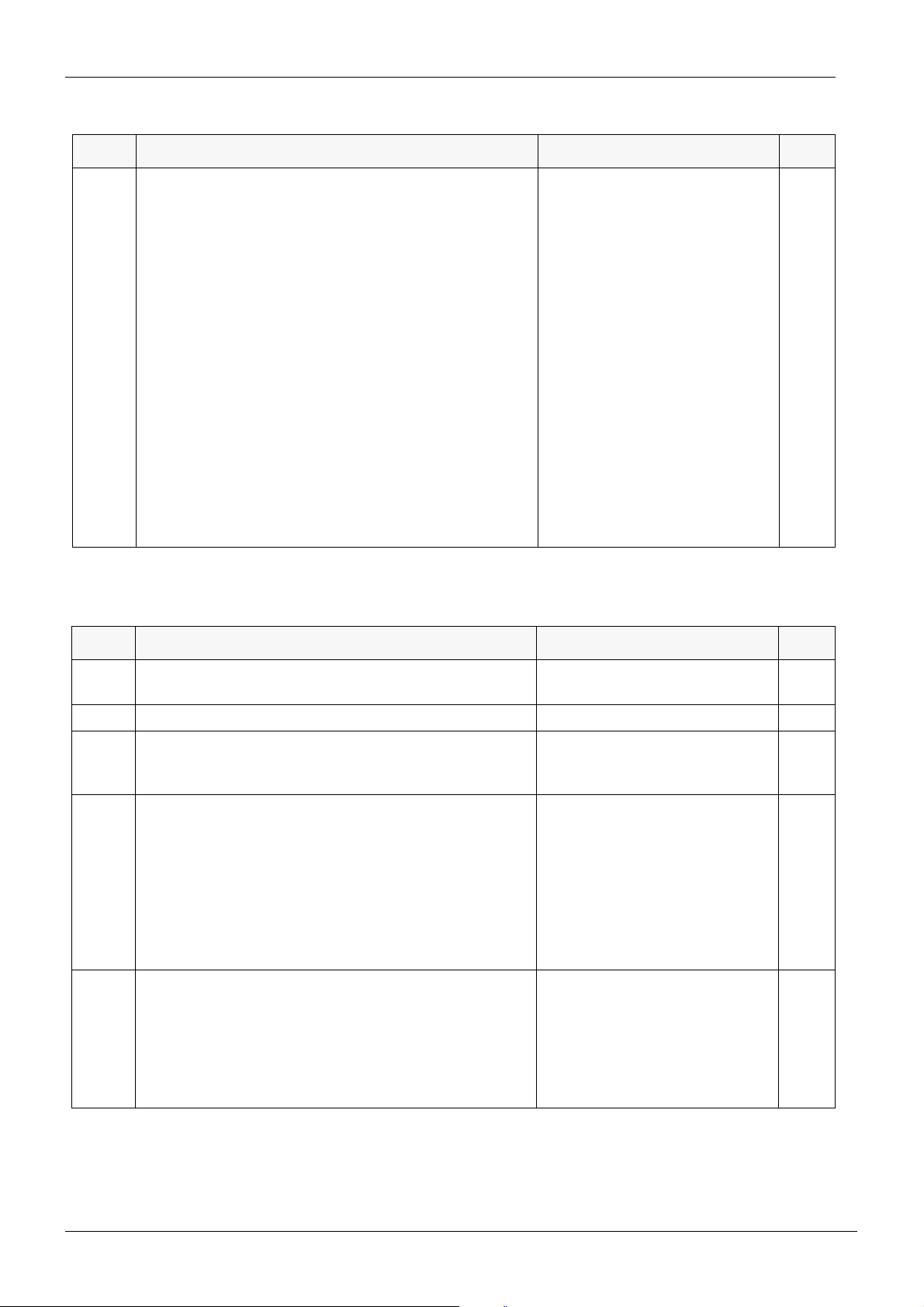
Chapter C - SERVICE MODE
GENERAL ABOUT THE SERVICE MODE
Table 6: Foot control related service modes
MODE SERVICE MODE FUNCTION DISPLAY/RANGE page
n.69 Momentary spray mode / spray with foot control mode 0 = momentary spray water off,
instrument spray with foot control
on (default)
1 = momentary spray water on,
instrument spray with foot control
on
2 = momentary spray water off,
instrument spray with foot control
disabled
3 = momentary spray water on,
instrument spray with foot control
disabled
4 = momentary spray disabled,
instrument spray with foot control
on
5 = factory use
6 = momentary spray disabled,
instrument spray with foot control
disabled
7 = factory use
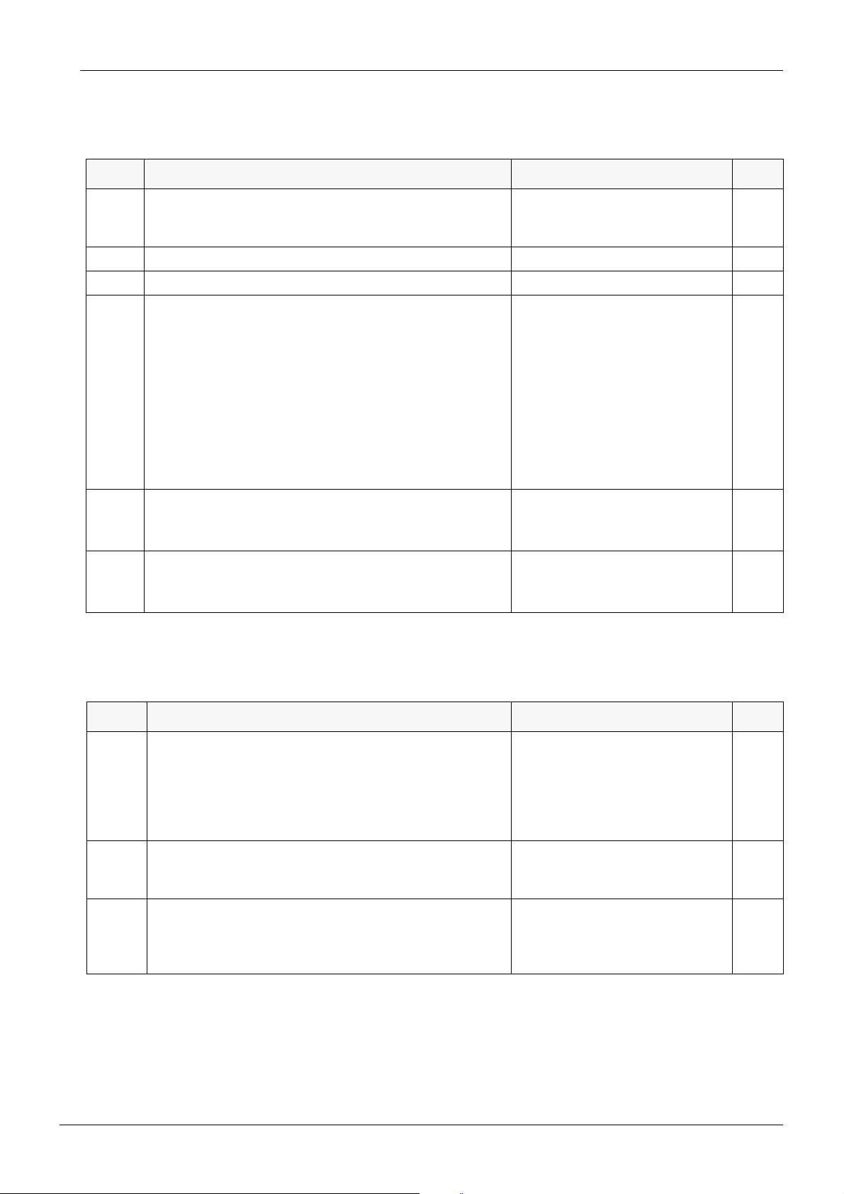
Table 7: Operating light related service modes
C-31
MODE SERVICE MODE FUNCTION DISPLAY/RANGE page
n 70 Show operating light button signal 0 = button released
C-32
1 = button pressed
n.71 Set OP-light maximum voltage nn.n VAC (default 18.5) C-32
n.72 Disable OP-light automatic turn off/on with chair 1 = synchronized with chair
C-32
(default)
0 = completely independent
n.73 Disable OP-light automatic dimming with instrument con-
sole curing lights (not curing light in suction holder)
0 = completely independent
1 = automatic dimming, light
C-32
returns to initial brightness when
the polymerization cycle is
stopped (default)
2 = automatic dimming, light
returns to initial brightness when
an another instrument is selected
or operating light key is used.
n.74 Disable OP-light dimming function from its button 0 = dimmer function disabled
C-32
from OP-light push-button
1 = dimmer function enabled
(default)
2 = dimmer function disabled
from control panel button
3 = dimmer function disabled
C-8 Planmeca Compact i
Technical Manual
Page 37
GENERAL ABOUT THE SERVICE MODE
Chapter C - SERVICE MODE
Table 8: Patient chair related service modes
MODE SERVICE MODE FUNCTION DISPLAY/RANGE page
n 75 Show emergency stop switch signal 1 = emergency stop plate acti-
C-33
vated
0 = normal
n.76 Show lift mechanism position sensor signal nnn C-33
n.77 Show backrest mechanism position sensor signal nnn C-33
n.78 Select S position function mode 0 = previous position remains in
C-33
memory when you drive from the
spit position to an automatic position
(S key indicator light ON)
(default)
1 = previous position is cleared
from the memory when you drive
from the spit position to an automatic position (S key indicator
light OFF)
n.79 Lift mechanism position sensor calibration mode L-_ turn axle counterclockwise
C-33
L-- ok
–
turn axle clockwise
L-
n.80 Backrest mechanism position sensor calibration mode b-_ turn axle counteclockwise
C-34
b-- ok
–
b-
turn axle clockwise
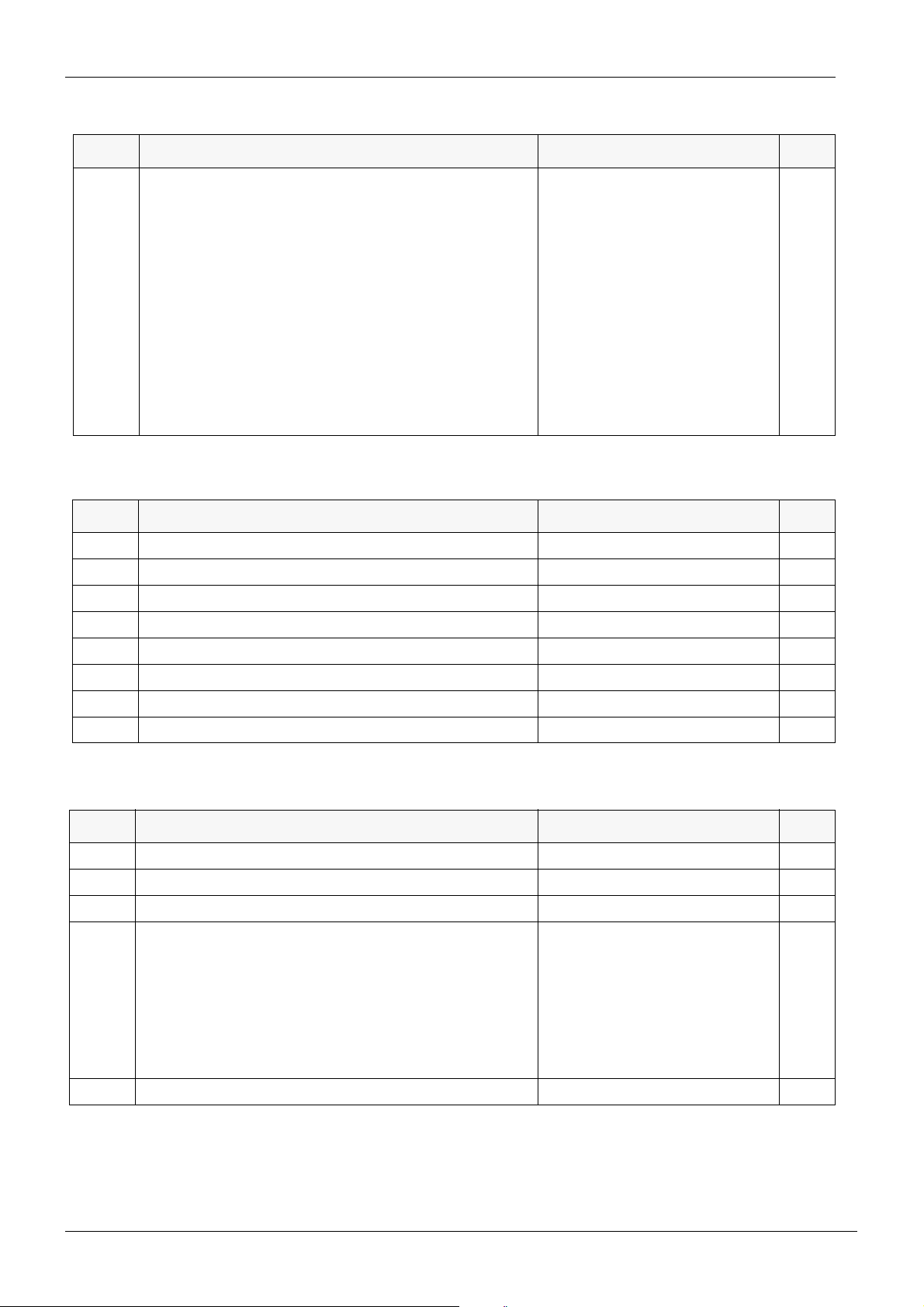
Table 9: Separator/suction system related service modes
MODE SERVICE MODE FUNCTION DISPLAY/RANGE page
n 81 Show type of installed suction system 0 = Wet (or no) suction system
C-34
1 = Microvac II (Planmeca)
2 = Dürr Combisep
3 = Metasys
4 = Dürr VSA
5 - 7 = reserved
n.82 Set suction motor turn-off delay mm.ss = minutes.seconds
C-34
Cont = Continuously on
(default 00.03 = 3 seconds)
n.83 Set number of suction hoses / disable suction system 0 = no suction system in unit
C-34
1 = one suction hose only
2 = two hoses (default)
3 = three hoses (maximum)
Technical Manual
Planmeca Compact i C-9
Page 38
Chapter C - SERVICE MODE
GENERAL ABOUT THE SERVICE MODE
Table 9: Separator/suction system related service modes
MODE SERVICE MODE FUNCTION DISPLAY/RANGE page
n.84 Set type of extra assistant instrument 0 = no extra assistant instrument
C-35
1 = assistant’s syringe
2 = water operated saliva ejector
3 = assistant’s syringe and water
operated saliva ejector
4 = PM Starlight LED polymerization light
5 = assistant’s syringe and PM
Starlight
6 = water operated saliva ejector
and PM Starlight
7 = assistant’s syringe, water
operated saliva ejector and PM
Starlight
Table 10: MCB CPU direct I/O related service modes (for factory use)
MODE SERVICE MODE FUNCTION DISPLAY/RANGE page
n 85 Show IC36 output signals ¦¦¦¦¦¦¦¦ C-35
n 86 Show IC37 output signals ¦¦¦¦¦¦¦¦ C-35
n 87 Show IC29 driver signals ¦¦¦¦¦¦¦¦ C-35
n 88 Show IC31 driver signals ¦¦¦¦¦¦¦¦ C-36
n 89 Show IC14 input signals ¦¦¦¦¦¦¦¦ C-36
n 90 Show IC16 input signals ¦¦¦¦¦¦¦¦ C-36
n 91 Show port A outputs (IC4) ¦¦¦¦¦ C-36
n 92 Show port A inputs (IC4) ¦¦¦ C-36
Table 11: Other service modes
MODE SERVICE MODE FUNCTION DISPLAY/RANGE page
n.93 Adjustment of the duration of the spray water impulse 0 - 20, default = 1 C-37
n.94 Set syringe fibre optic light voltage 0 - 4 V, default = 3.7 V C-37
n.95 Set spray water impulse pressure 0 - 30, default = 15 C-37
n.96 RPM display / Enable low speed function for brush micro-
motors (Optional Plus package)
0 = RPM disabled / low speed
function disabled
C-37
1 = RPM disabled / low speed
function enabled
2 = RPM enabled / low speed
function disabled
3 = RPM enabled / low speed
function enabled
n.97 Set suction system cleaning time 0 sec. - 20 min, default = 2 min C-37
C-10 Planmeca Compact i
Technical Manual
Page 39

GENERAL ABOUT THE SERVICE MODE
Chapter C - SERVICE MODE
Table 11: Other service modes
MODE SERVICE MODE FUNCTION DISPLAY/RANGE page
n.98 Select how to freeze Intracam image from foot control 0 = pedal movement has no
effect
1 = pedal movement activates
door open/nurse call relay (video
printer freeze)
2 = pedal movement activates
serial communication w. Dimaxis
(default)
(pedal to the left = toggle freeze/
unfreeze image,
pedal to the right = save image)
3 = pedal movement activates
relay and serial communication
(1 + 2)
4 - 7 are the same as 0 - 3 but the
pedal operation is vertical.
n.99 Instrument hose flushing operation: disable HE 99 mes-
sage
0 = HE 99 is not displayed
(default)
1 = HE 99 will show, but does not
affect the unit functions
2 = HE 99 will show and the long
flushing must be performed.
n.100 Select dental unit type 0 = Prostyle Compact unit without
chair
1 = Prostyle Compact unit
2 = Prostyle Compact WE’S unit
3 = reserved for future use
4 = Planmeca Compact e
5 = Planmeca Compact i without
chair
6 = Planmeca Compact i
7 = Planmeca Compact e with
swivel position recognition
8 = Planmeca Compact i unit
without chair, connected to Planmeca Chair
9 = Planmeca Simulation Unit
---- = unit type not selected
C-37
C-38
C-38
n.101 Interrupt waterline cleaning operation 0 = normal operation (default)
1-6 = waterline cleaning operation on
n.102 Disable dry spray mode when using Plus Package 0 = dry spray mode enabled
1 = dry spray mode disabled
(Plus package signal tones)
2 = dry spray mode disabled
(Normal signal tones)
(default = 0)
Technical Manual
Planmeca Compact i C-11
C-38
C-39
Page 40
Chapter C - SERVICE MODE
GENERAL ABOUT THE SERVICE MODE
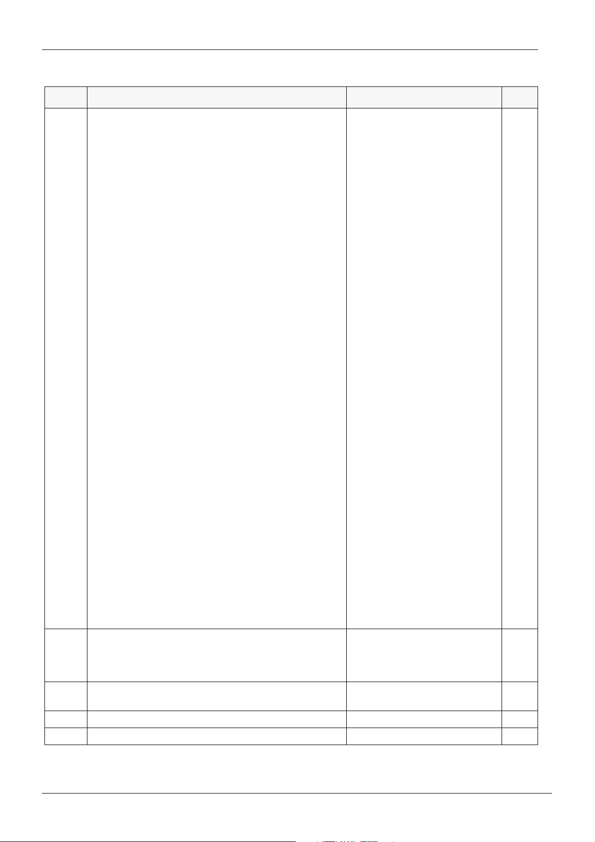
Table 11: Other service modes
MODE SERVICE MODE FUNCTION DISPLAY/RANGE page
n 103 Show the dental unit type First digit shows type of Main
PCB:
2 = Planmeca Compact i
Second digit shows IMUX version:
0 = no IMUX
1 = IMUX PCB version E or older
2 = IMUX PCB version F-G
(1.08.x)
3 = IMUX PCB version F-G
(1.09.x or 1.10.x)
4 = IMUX PCB version H or never
Third digit shows dental unit type:
0 = Prostyle Compact
1 = Planmeca Compact e
2 = Planmeca Compact i
Fourth digit shows patient chair
type:
0 = no patient chair
1 = Prostyle Compact chair without legrest or legrest up
2 = Prostyle chair with legrest
down
3 = WE’S lifter
4 = Planmeca Compact e chair
5 = Planmeca Compact i chair
with fixed legrest; or automatic
legrest up
6 = Planmeca Compact i chair
with 510 automatic legrest; in
automatic state
7 = Planmeca Compact i chair
with 460 automatic legrest; in
automatic state
8 = Planmeca Compact e with
swivel position recognition and
fixed legrest
9 = Planmeca Compact e with
swivel position recognition and
automatic legrest
A = Planmeca Compact e swivelled to 90° with automatic legrest
n. 104 Instrument multiplexer additional water valve control 0 = disabled (default)
1 = reserved for factory use
2 = enabled
A = automatic
C-39
C-39
n.105 Enable/disable instrument places ¦¦¦¦¦ ( = all instrument places
C-39
enabled, default)
n.107 Triggering level of Er45 adjustment 1..17 (17 = default) C-40
n.108 Stopping delay for instrument spray air 0..15 (4 = default) C-40
C-12 Planmeca Compact i
Technical Manual
Page 41
GENERAL ABOUT THE SERVICE MODE
Chapter C - SERVICE MODE
Table 11: Other service modes
MODE SERVICE MODE FUNCTION DISPLAY/RANGE page
n.109 Unit type setting to enable or disable the IMUX and the
door features
0 = Compact i
1 = Compact e
C-40
28 = Cart
31 = Independent Cart
44 = no Instrument Console
n 110 Show IC39 outputs For factory use C-40
n 111 Show inputs IN3 (IC39) For factory use C-41
n 112 Show inputs IN4 For factory use C-41
n 113 Show side delivery arm emergency switches signals ---- = no side delivery arm
C-41
DxUy; x = downwards switch
y = upwards switch
0 = switch not activated
1 = switch activated
n 114 Show bowl position 0 = bowl not in rest position
C-41
1 = bowl in rest position
n 115 Show glass identification signal 0 = glass is not in holder
C-41
1 = glass is in holder
n.116 Select glass filling mode 0 = no identification
C-41
1 = glass identification activated
(default)
2 = automatic glass filling
n 117 Show active time of drive air pulse width modulation For factory use C-41
n 118 Show active time of spray water pulse width modulation For factory use C-41
n 119 Show active time of spray air pulse width modulation For factory use C-41
n 120 Show active instrument power consumption nn W C-42
n.121 Select the length of the automatic legrest 0 = 510 (default)
C-42
1 = 460
2 = 390
n.122 Armrest selection 0 = armrests deselected
C-42
1 = armrests selected (default)
n.123 Factory test - C-42
n.124 Set the type of Planmeca Compact i 0, 1 C-42
n 125 Show Water management system status nnn C-42
n 126 Show Water management system inputs and outputs ¦¦¦¦¦¦¦¦ C-43
n.127 Water management system water flow adjustment C-43
n.128 Fake pressure sensor readings 0 = normal
1 = fake pressure readings
n.129 Adjustment of the upper limit of pre-programmed chair
C-43
positions
n.130 Disable WCS 0 = WCS in use (default)
C-43
1 = Starting of WCS disabled
2 = WCS totally disabled
n.131 WCS: adjustment of the syring cleaning solution filling
20 - 180, (default = 40) C-44
time
Technical Manual
Planmeca Compact i C-13
Page 42

Chapter C - SERVICE MODE
GENERAL ABOUT THE SERVICE MODE
Table 11: Other service modes
MODE SERVICE MODE FUNCTION DISPLAY/RANGE page
n.132 Disable beeper sounds 0 = beeper on (default)
1 = beeper disabled
n.133 Operating light mode 0 = not installed (even buttons do
not work)
1 = installed (no errors from bulb
burned out) (default)
2 = installed with errors from bulb
burned out (shows E 58).
C-44
n.134 Motorized headrest 0 = not installed (will show error
E80.2 if it is installed)
1 = installed (will show E80.1 if it
is not installed)
2 = automatic recognition of
headrest (default)
n.135 WMS operation 0 = disabled totally (no operation,
no error messages)
1 = not installed (will show error
E63.1 if it is installed)
2 = installed (will show error
E63.2 if it is not installed)
3 = automatic WMS recognition.
Default is 3 (automatic WMS recognition).
n.136 Disable motorized headrest automatic positions 0 = Automatic positions enabled
(default)
1 = Automatic positions disabled
n.137 Bowl rotation safety features 0 = Bowl roation is not included in
the safety circuit
1 = Bowl roation is included in the
safety circuit (default)
n.138 Simulation system type 0 = IDSS - Interactive Digital Sim-
ulation System
1 = ASW-1 - Advanced Simulation Workplace Single (Main
Valves are in normal use)
2 = ASW-N - Advanced Simulation Workplace (Main Valves are
not in use)
n.139 Duration of long instrument hose flushing 2 - 9 minutes.
(default 2 minutes)
C-44
C-44
C-44
C-45
C-45
C-45
n.140 Suction valve closing time adjustment 0 - 3 seconds
C-45
(default is 0)
n 200 Boot information bits For factory use C-45
n 201 Boot software checksum For factory use C-45
n 202 Main software checksum For factory use C-45
n.203 Processor watchdog test. Restarts the dental unit with
C-45
error E 75.1.
n.204 Processor reset test. Restarts the dental unit without
C-45
errors.
C-14 Planmeca Compact i
Technical Manual
Page 43
GENERAL ABOUT THE SERVICE MODE
Chapter C - SERVICE MODE
Table 11: Other service modes
MODE SERVICE MODE FUNCTION DISPLAY/RANGE page
n.205 Lifter height calibration in millimetres (mm) C-45
n.206 Backrest angle calibration in degrees (deg) C-45
n 207 Headrest length in millimetres (mm) in relation to calibra-
C-46
tion point and virtual origo point
n 208 Headrest height in millimetres (mm) in relation to back-
C-46
rest zero-level and virtual origo point
n 209 Headrest angle in degrees (deg) in relation to backrest
C-46
angle and virtual origo point
n 300 Headrest communication status C-46
n.301 Headrest software major version C-47
n.302 Headrest software minor version C-47
n.303 Upgrade headrest software C-47
n.304 Headrest manual angle rotation speed Min = 0, Max = 15
C-47
Default = 6
Larger value is faster
n.305 Headrest manual height movement speed Min = 0, Max = 15
C-47
Default = 6
Larger value is faster
n.306 Headrest manual length movement speed Min = 0, Max = 15
C-47
Default = 10
Larger value is faster
n.307 Headrest automatic movement speed Min = 0, Max = 15
C-47
Default = 6
Larger value is faster
n.308 Headrest length current limit value Min = 0, Max = 15
C-47
Default = 11
Larger value = needs more current (force) to stop
n.309 Headrest joint 2 closing gap stopping term value Min = 0, Max = 15
Default = 0
Larger value = stops less easy,
might be needed to increase
when using faster speeds
n.310 Headrest joint 2 (near cushion) ADC-value 528 -908 C-47
n.311 Headrest joint 1 (near backrest) ADC-value 85 - 477 C-47
n.312 Headrest length ADC-value 178 - 954 C-48
n 313 Headrest joint 2 (near cushion) drive WITHOUT limits
and potentiometer in Set mode
n 314 Headrest joint 1 (near backrest) drive WITHOUT limits
and potentiometer in Set mode
Displays text “H2- ” on the display
in Set mode
Displays text “H1- ” on the display
in Set mode
n 315 Headrest length calibration C-48
n 316 Headrest joystick directions and buttons C-48
n 317 Potentiometer select line test C-48
n.318 As service mode n.18 but only headrest endurance test For factory use. C-48
Technical Manual
Planmeca Compact i C-15
C-47
C-48
C-48
Page 44

Chapter C - SERVICE MODE
GENERAL ABOUT THE SERVICE MODE
Table 11: Other service modes
MODE SERVICE MODE FUNCTION DISPLAY/RANGE page
n 319 As service mode n.18 but chair and headrest endurance
For factory use. C-48
tests
n.320 Headrest right joystick horizontal ADC-value C-49
n.321 Headrest right joystick vertical ADC-value C-49
n.322 Headrest left (cabinet side) joystick horizontal ADC-value C-49
n.323 Headrest left (cabinet side) joystick vertical ADC-value C-49
n.999 Main program loop speed For factory use. C-49
C-16 Planmeca Compact i
Technical Manual
Page 45

SERVICE MODE DETAILED DESCRIPTION
Chapter C - SERVICE MODE
2 SERVICE MODE DETAILED DESCRIPTION
The following pages contain detailed information about the service modes, giving useful information on how to use and interpret the information available. Reading this chapter gives a
good understanding of the unit’s control system. Used abbreviations are explained in the
beginning of this manual.
Underlined number or values in the heading texts are factory default values.
2.1 MAIN control system related service modes
n.0 Disable programming and limit micromotor speed
(For educational establishment use.) In this mode the programming of the instrument, unit
and/or chair settings can be disabled, and the micromotor power can be limited to 50% of the
maximum speed.
The following settings are possible. The factory default is 0 (zero).
instrument
settings
disabled
0
1x
2x
3x x
4x
5x x
6xx
7x x x
8x
9x x
10 x x
11 x x x
12 x x
13 x x x
14 x x x
unit settings
disabled
chair settings
disabled
micromotor
speed limited
Technical Manual
15xxxx
Planmeca Compact i C-17
Page 46

Chapter C - SERVICE MODE
n 1 Show software version on MCB (n.nn.n version)
Shows the currently installed software version on the MCB. Shows normally version number
(“3.02.5” ie. 3 = Major version, 02 = minor version and 5 = fix version). When in Set-mode,
shows “234.b” where 234 is build version and b can be d, b or r where d for development, b
for beta and r for release.
The software version is also briefly displayed whenever the unit is turned on. There is normally also a label on top of the software chip containing the same information.
The unit’s behaviour, features and functions depend completely on the installed software.
Always use the latest software available, especially if you notice that some features are missing described in any available documentation.
Some new instruments or retrofittable extensions might require a MCU software upgrades. In
this case the unit will display automatically respective help or error codes (HE9, HE14, E16,
E19.n, E32.n, E47.n, E52, E62).
The foot-control and the IMUX also both contain microprocessors. Their software is “embedded” inside their respective CPU’s and cannot therefore be replaced. Since the “main brain” is
the MCB and its microprocessor, there is rarely ever a need for this. However, you can check
their software versions by using service modes n19 and n60 (respectively).
n 2 Show internal unregulated operating voltage (nn.n volt)
SERVICE MODE DETAILED DESCRIPTION
This voltage reflects mains voltage magnitude variations. The nominal value is +33VDC and
is allowed to vary ± 15% (28...38V) without affecting the normal operation of the unit.
If one of the MCB electronics fuses (F9 or F10) is blown, the display will only be half of normal
(Ý16.5VDC ± 15%). If the internal voltage is too low or too high, the unit will show respective
error codes (E9 or E10). If the internal voltage rises above 44VDC (a heavy mains surge, too
high mains voltage, wrong voltage jumper position or wrong transformer primary wiring), an
internal protection circuitry will blow fuses F9 and F10, protecting the unit electronics from failure.
n 3 Show output current of IPS (n.nn ampere)
This is the output current of the instrument power supply (IPS) located on the MCB. This
microprocessor controlled power supply feeds power to micromotors, light-curing bulbs and
scaler units. This built-in ampere meter is intended for checking the current consumption of
the selected instrument. If the current is continuously zero it indicates an open-circuit somewhere between the MCB and the instrument. This mode is also good for checking the no-load
current of micromotors, that is a direct indication of the motor condition.
n 4 Show output voltage of IPS (n.n volt)
This is the output voltage of the instrument power supply (IPS) located on the MCB. This
microprocessor controlled power supply feeds all micromotors, light-curing bulbs and scaler
units with appropriate voltages. The voltage on the display is measured directly at the IPS
output on the MCB, therefore the voltage shown is normally somewhat higher than the instrument receives. However, the voltage drop in the cabling is compensated for so that instruments always receive a proper voltage.
C-18 Planmeca Compact i
Technical Manual
Page 47

SERVICE MODE DETAILED DESCRIPTION
n 5 Show scaler electronics ID-code (n id-code) and
connection point of the scaler electronics (--n-) or (---n)
The (optionally) installed scaler electronics module is identified by a jumper wire on its connector that plugs to the MCB. It is important for the MCB to know the type of scaler electronics
installed. This service mode allows you to check what type of scaler electronics is installed
and that the identification works properly. It is also possible to check if the scaler electronics is
installed on the MCB or at the IMUX.
The location of the scaler electronics is indicated on the display by pressing the S-key with
delay. If the display (--n-) is shown then the electronics is connected to IMUX or (---n) then the
electronics is connected to MCB.
0 No scaler electronics module installed
1 AMDENT scaler module installed
2 EMS scaler module installed
3 SATELEC scaler module installed
6 Newtron scaler module installed
4-5, 7 reserved
n 6 Show service door switch signal (n door status)
This is the signal from the microswitch that indicates the door status (1 = door open, 0 = door
closed). An open circuit, broken wire or loose connector is interpreted as the door would be
continuously open. During this condition the chair cannot be run, except for in the service
mode when the control system temporarily ignores this signal.
Chapter C - SERVICE MODE
n 7 Show mains frequency (nn.n Hz)
There is no other use for this service mode than checking the condition of a part of the MCB
electronics. If everything is OK the display should be stable within ±2 digits. Severe mains
voltage transients can up-set the display temporarily, and would also cause the OP-light to
flicker. If this display is stable but the OP-light flickers occasionally, it’s probably caused by a
bad bulb socket.
n 8 Show (optional) assistant syringe hose ID (n id-code)
If no hose is connected (or if the assistant syringe option is not installed) the display should
show a dash “-”. If any other instrument than a syringe is connected then the display should
show 0 (zero). If a valid syringe (hose) is connected then the display shows the syringe hose
ID-code (e.g. 20).
n 9 Show (optional) assistant syringe hose sense signal (nnn
signal)
Same as above but this is the direct signal from the assistant syringe hose identification circuitry. The display range is 0-255. 255 indicated an open circuit, 0 indicated a short, any other
values represent the signal. The display should be fully stable within one digit.
n 10 Show MCB heatsink temperature (nn °Celsius or
°Fahrenheit)
Technical Manual
The temperature is measured inside the black aluminum block on the MCB. During normal
circumstances the temperature should stay below 55°C. The temperature can rise above this
level if the fixing screws (that attach the heatsink to the aluminum box) are missing. To protect
against overheating the CPU turns off those loads that contribute to the power dissipation
(OP-light and IPS) if the temperature rises above 60°C, The error E15 is then also displayed.
Planmeca Compact i C-19
Page 48

Chapter C - SERVICE MODE
n.11 Enable (optional) water heater (n mode = 0, 1)
The purpose of this mode is to guarantee that the (optional) water heater is not powered up
without water. When the unit is shipped from the factory the mode is set to 0 (heater off). During the installation (but after the water and drain is connected) this mode should be set to 1 (if
there is a water heater attached). When the mode is set to 1, water will be flown from the
glass fill for 10 seconds.
n.12 Set main air valve operation (n mode = 0, A, 1)
The main (incoming) air valve is controlled by the CPU. The operation is automatic, in other
words, the valve opens only when necessary. This behaviour can be temporarily bypassed in
this service mode. Set the mode to 0 (zero) to keep the valve continuously closed, set to “A”
to go back to automatic or set to 1 to force the valve to open. Please note that even if this
mode is programmed to 0 or 1, it always automatically defaults to “A” after turning off the
power to the unit.
n.13 Set main water valve operation (n mode = 0, A, 1)
The main (incoming) water valve is controlled by the CPU. The operation is automatic, in
other words, the valve opens only when necessary. This behaviour can be temporarily
bypassed in this service mode. Set the mode to 0 (zero) to keep the valve continuously
closed, set to “A” to go back to automatic or set to 1 to force the valve to open. Please note
that even if this mode is programmed to 0 or 1, it always automatically defaults to “A” after
turning off the power to the unit.
SERVICE MODE DETAILED DESCRIPTION
n.14 Disable automatic functions in S-position (n mode = 0, 1, 2,
3
)
This service mode can be used to disable automatic cuspidor flush and cup fill functions when
using the chair S-position. 0 = no automatic functions, 1 = cuspidor flush only, 2 = cup fill only,
3 = both.The factory default is 3 (all functions).
n.15 Disable error messages (n mode = 0, 1, 2)
This service mode can be used to disable the error message display system. The only use for
this mode is during exhibitions or in showrooms where a full installation is not possible (no
water and/or water pressure), and because of this error messages would be continuously displayed. Set the mode to 0 to disable the error messages, or to 1 to enable the error messages
(factory default), or to 2 to disable the error messages related to the console arm. The unit
shows shortly HE12 when turning the power on (remainder of that the error messages are
disabled).
C-20 Planmeca Compact i
Technical Manual
Page 49

SERVICE MODE DETAILED DESCRIPTION
n.16 Enable factory preset mode (- or S U)
This service mode is used to set the unit to a predefined state only using few keystrokes. This
feature is mainly used at the factory, that is why it is called a “factory preset”. All user programmable settings and parameters, as well as the most important service mode settings can
be set to a “normal” state. Then the unit can be immediately operated without having first to
do any adjustments or programming. This is useful also on the field if a showroom unit is
installed later for clinical use.
Upon entry this service mode shows a dash (-) in the display. Press the S-key for 2 seconds
(prevents accidental entry) so that the yellow LED lights in the key. The display now shows S
U.
Performing user mode presets
Press the B-key briefly (“below” the U symbol in the display) to perform the user mode presets
(the display shows FP.U during the process). Pressing the B-key sets the factory presets for
the user-controlled settings, which are: period of glass filling, period of bowl rinsing, period of
door open/nurse call, settings of the dentists (chair positions: backrest, height, light), timer
settings, intensity of the operating light and instrument settings (spray, power reduction, chip
blow etc.). After performing the user mode presets the text “turn off” will flash on the display.
Now turn off the unit.
Chapter C - SERVICE MODE
Performing service mode presets
Press the A-key briefly (“below” the S symbol in the display) to perform the service mode presets (the display shows FP.S during the process). Pressing the A-key sets the factory presets
for all the service mode settings. After performing the service mode presets the text “turn off”
will flash on the display. Now turn off the unit.
n.17 Select display units for pressures and temperature (n
mode = 1
The unit can show pressures (in the service mode) in either bar, kPa or PSI. Select mode 1 to
show the pressure in bar (factory default), 2 to show the pressures in kPa (kiloPascal), or 3 to
show the pressures in PSI (pounds per square inch). If mode 3 is selected additionally temperature displays (ex. service mode 10) are shown in °Fahrenheit instead of °Celsius. Select
mode 4 to show the pressure in PSI and temperature in °Celsius.
, 2, 3, 4)
n.18 Factory test
Reserved for factory use.
Technical Manual
Planmeca Compact i C-21
Page 50

Chapter C - SERVICE MODE
SERVICE MODE DETAILED DESCRIPTION
2.2 Instrument MUX related service modes
n 19 Show software version of IMUX CPU (n.nn software version)
This is the software version of the embedded software inside the IMUX CPU EEPROM. This
software can be updated on the field.
n 20 Show instrument holder & AUX-input signals (¦ ¦¦¦¦¦
signal)
This service mode is convenient for checking the proper operation of the doriot arm sensors
(on the IMUX PCB). The 5 rightmost segments represent the 5 instrument positions, from
right to left respectively. A short vertical bar indicated that the instrument is in the holder, a
long vertical bar that it is taken out from the holder. The leftmost vertical bar shows the signal
at the AUX input terminal on the IMUX PCB (6th instrument place).
n 21 Show active instrument hose ID-code (---- or nn ID-code)
This mode is convenient for checking the instrument hose ID-code and the related electronics
on the IMUX PCB. The code range is 1 to 26.
The display shows four dashes (----) if no instrument is selected. Activate a properly attached
instrument hose (in this same location) to display the ID-code. The code displayed should be
the same as indicated by the last digit(s) on the label on the quick connector.
n 22 Show active instrument hose identification signal (nnn
signal)
This service mode is similar to the one above. This mode shows the actual signal measured
from the identification pins on the instrument hose quick connector. The signal range is 0 to
510.
The display should show 223 to 228 when no instrument is selected (the electronics meas-
ures a local reference signal). If the signal is outside this range then there is an error on the
IMUX PCB. Check for any water leakage.
Activate a properly attached instrument hose (in this same location) to display the identification signal.
n 23 Show active instrument switch/sensor signal (---- or nnn
signal)
This service mode shows the instrument (optional) switch or sensor input signal. The display
shows four dashes (----) if no instrument is selected. The display range is 0 to 255.
Activate a properly attached instrument hose (in this same location) to display the ID-code.
n 24 Show console syringe location hose ID-code (nn ID-code)
This service mode shows the hose ID-code for the hose connected to the syringe location.
The display shows zero (0) if no hose is attached, otherwise the hose ID-code is displayed
continuously.
C-22 Planmeca Compact i
Technical Manual
Page 51

SERVICE MODE DETAILED DESCRIPTION
n 25 Show console syringe location hose identification signal
(nnn signal)
This service mode shows is similar to the one above. This mode shows the actual signal
measured from the identification pins on the connected hose. The display range is 0 to 255. A
continuous 255 indicates an open circuit, a continuous 0 a short. The signal should be stable
within ± 1 digit.
n 26 Show console syringe switch signal (nnn signal)
This service mode shows the (optional) switch signal from the syringe. At this moment no
syringes use this signal, therefore 255 is always shown.
n 27 Show IMUX on/off valve signals (¦¦¦¦¦¦ signal)
This service mode shows the actual driver output signals controlling the on/off type electromagnetic valves inside the IMUX. The five first vertical segments (counting from right) represent the four instrument and one syringe select valves, respectively.
The sixth (leftmost) vertical bar shows the (optional) steripump control valve / extra water
valve signal.
A short vertical bar indicates that the valve is off and that the valve is connected properly (not
open circuited). A long vertical bar indicates that either the valve is on or that the valve is
open circuited.
Chapter C - SERVICE MODE
When the SET-mode is entered, IMUX IC16 output signal feedback inputs are displayed:
1st vertical segment (counting from right): Syringe water control
2nd: Instrument 4 membrane control valve
3rd: Instrument 3 membrane control valve
4th: Instrument 2 membrane control valve
5th: Instrument 1 membrane control valve
6th: steripump control valve / extra water valve
7th: Syringe fibre light electronics
8th: Syringe heater
n 28 Show IMUX other output signals (¦¦¦¦¦¦ signal)
This service mode is similar to the one above. This mode shows the other outputs driver statuses controlling the relays and other outputs. This service mode is mainly intended for factory use.
n 29 Show air / water pressure difference
This service mode shows the measured pressure difference between the internal continuous
air pressure and the regulated spray water fed to the instruments. This pressure difference
should always be greater than 1 bar (100kPa) to guarantee proper operation.
n 30 Show active instrument drive/cooling air pressure
(n.nn bar; nnn kPa; nn.n PSI pressure)
Technical Manual
This service mode shows the signal from the drive/cooling air line pressure sensor. The display is either in bar, kPa or PSI, depending of the setting in the service mode n.17. The pressure is measured inside the IMUX just after the proportional valve controlling this line.
Therefore this pressure display is (under normal flow conditions) always higher than the pressure measured at the instrument end of the hose.
Planmeca Compact i C-23
Page 52

Chapter C - SERVICE MODE
n 31 Select the service mode navigation type (0, 1, 2, 3)
In this service mode the service mode navigation type can be selected.
0 = Normal navigation. The service mode number is changed in steps of one when using the
chair up and down keys (“C” or “D”) on the control panel.
1 = factory use
2 = Accelerated navigation. The service mode number is changed in steps of 5 when the chair
up or down is pressed and held down.
3 = factory use
The factory default is 2.
n 32 Show active instrument spray air pressure
(n.nn bar; nnn kPa; nn.n PSI pressure)
This service mode shows the signal from the spray/chip air line pressure sensor. The display
is either in bar, kPa or PSI, depending of the setting in the service mode n.17. The pressure is
measured inside the IMUX just after the proportional valve controlling this line. Therefore the
pressure measured (under normal flow conditions) is always higher than this same pressure
measured at the instrument end of the hose.
n.33 Factory test
SERVICE MODE DETAILED DESCRIPTION
Reserved for factory use.
n 34 Show active instrument spray water pressure
(n.nn bar; nnn kPa; nn.n PSI pressure)
This service mode shows the signal from the spray water line pressure sensor. The display is
either in bar, kPa or PSI, depending of the setting in the service mode n.17. The pressure is
measured inside the IMUX just after the proportional valve controlling this line. Therefore the
pressure measured (under normal flow conditions) is always higher than this same pressure
measured at the instrument end of the hose. Because of the construction of the water channel
the pressure drops very slowly towards 0 (zero).
n 35 Factory test
Reserved for factory use.
n.36 Set mode of IMUX membrane operation (n mode = 0, 1)
This service mode selects the mode of operation of the IMUX instrument select membrane
control valves. The unit software must be upgraded if mode 1 is not available and needs to be
used. This feature was added to the software version 1.23 (and later).
Mode 1 is recommended to be selected in new units, since in this mode all instrument select
membranes in the IMUX will stay normally closed (pressurized). The benefit is that there is no
risk of water leakage or occasional water drops from the instruments. In this mode the integral
spray water back pressure valves are only needed when the unit is powered off. This continuous activation of the (4) valves causes some additional heat dissipation in the IMUX (about
8W). Early IMUX assemblies have not been tested with this higher power dissipation and
could give problems (due to some tight tolerances) with sticking doriot arm pins. Assuming
that the pins are replaced with thinner ones, then the mode 1 can be used in all IMUXes.
Mode 0 is recommended to be selected in older units with IMUX assemblies manufactured
earlier than Jan. -96. In this mode all instrument select membranes stays whenever possible
open (not pressurized). Then prevention of water dropping from instruments (when idle) is
fully dependent of the operation of the integral back pressure valves.
C-24 Planmeca Compact i
Technical Manual
Page 53

SERVICE MODE DETAILED DESCRIPTION
n.37 Disable turbine contamination prevention system (n mode
Chapter C - SERVICE MODE
= 0, 1
This service mode can be used to disable the software controlled turbine contamination prevention system. It is recommended to keep this mode turned on (1) at all s to guarantee maximum turbine hygiene.
Set this mode temporarily
turbine performance. This demonstration should be done with the turbine connected to an
instrument location not having a built in CP (contamination prevention) valve (no label close
to the IMUX quick connector).
The turbine contamination prevention system is based on a sophisticated software algorithm
that controls the turbine in such a way that the turbine head can never produce vacuum,
therefore minimizing the risk of contaminating the turbine or the turbine quick-connector.
)
to 0 (zero) if you want to compare or demonstrate the difference in
n 38 Show internal water or air pressure (A H)
This service mode can be used to check the internal water and air pressures.
Checking the air pressure (An.nn bar; Annn kPa; Ann.n PSI)
Press the A-key
pressure either in bar, kPa or PSI (depending on the setting in service mode 17). The display
stabilizes within a few seconds. The static air pressure should be 5.5 bar (550 kPa).
Checking the water pressure (Hn.nn bar; Hnnn kPa; Hnn.n PSI)
Press the B-key
water pressure either in bar, kPa or PSI (depending on the setting in service mode 17). The
display stabilizes within a few seconds. The static water pressure should be 2.5 to 2.8 bar
(250 to 280 kPa).
to enter the air pressure measurement mode. The display shows the air
to enter the water pressure measurement mode. The display shows the
NOTE Please make sure that there is at least one water consuming instrument hose
connected before performing the water pressure measurement (a scaler, turbine or micromotor hose). Leaving the water pressure measurement mode
causes the unit to turn off valves in the console, resulting in a small amount of
water (a few drops) flowing out from the IMUX. This behaviour is fully normal
and is due to the way the measurement is performed (using the spray water
line sensor).
Technical Manual
Planmeca Compact i C-25
Page 54

Chapter C - SERVICE MODE
2.3 Instrument related service modes
n.39 Set maximum fibre optic and Intracam bulb voltage for
selected hose type
(---- or n range = <0... 0 ...0>)
This service mode can be used to fine adjust the maximum allowed fibre-optic light bulb voltage for the selected hose type. The display shows four dashes (
selected. When a hose (instrument) that contains a fibre-optic light is selected the displays
shows the setting for this hose type. The factory default is 0 (zero). Positive values increase,
negative decrease the factory default. Each step equals about 50mV. Determine the bulb voltage by measuring it directly at the bulb socket when the bulb is on. Never exceed the maximum allowed voltage.
n.40 Fine-adjust bulb voltage for selected polymerization light
(---- or n range = <0... 0 ...0>)
This service mode can be used to fine adjust the polymerization light bulb voltage. The display shows four dashes (
is 0 (zero). Positive values increase, negative decrease the factory default. Each step equals
about 50mV. Determine the bulb voltage by measuring it directly at the bulb socket when the
bulb is on. Never adjust the voltage higher or lower than rated.
----) if no valid polymerization light is selected. The factory default
SERVICE MODE DETAILED DESCRIPTION
----) if no valid hose is
n.41 Set fibre optic light turn-off delay for all instruments (nn
seconds)
This service mode can be used to alter the turn-off delay for instruments with an internal fibrelight. The factory default is 30 seconds.
n.42 Fine-adjust cooling air pressure for selected hose type
(---- or n range = <0... 0 ...0>)
This service mode can be used to fine adjust the cooling air pressure (flow rate) to the
selected hose (instrument) type. The display shows four dashes (
selected. Valid hoses are all micromotors, polymerization lights without a built-in fan (Lysta,
Satelec) and IntraCam. The factory default is 0 (zero). Positive values increase, negative
decrease the factory default. Using too little air could overheat the instrument. Using too
much air can cause other problems (light guides or handpieces popping off).
----) if no valid hose is
n.43 Set mode of foot controlled chip-blow (n range = 0,1, 2)
This service mode can be used to alter the behaviour of the manual (foot controlled) chip
blow. The factory default is 2: no chip blow.
The setting 1 results always in a air-only (dry) manual chip blow, independent of the instrument automatic chip blow water/air flow selection. The setting 0 causes the manual chip blow
to behave the same way as the automatic one.
n.44 Fine-adjust drive air pressure for selected hose type
(---- or n range = <0... 0 ...0>)
This service mode can be used to fine adjust the air driven instrument's maximum drive air
pressure for the selected hose (instrument) type. The display shows four dashes (
valid hose is selected. Valid hoses are all turbine- and air-motor hoses. The factory default is
0 (zero). Positive values increase, negative decrease the factory default.
C-26 Planmeca Compact i
----) if no
Technical Manual
Page 55

SERVICE MODE DETAILED DESCRIPTION
2.4 Control panel related service modes
n 45 Show control panel type/AUX input for branch 1 (n = -, 0, 1,
2, 3)
This service mode shows the type of the control panel connected to the MCB branch 1 (normally the dentist's console control panel). A dash (-) indicates either that no control panel is
connected to this branch, the cable to the panel is loose or faulty, or that the panel itself does
not respond. The numbers 0-3 show that the panel is communicating with the MCB. 0 =
nurse’s panel, 1 = doctor’s panel, 2 = nurse’s plus panel, 3 = doctor’s plus panel.
n 46 Show control panel type/AUX input for branch 2 (n = -, 0, 1,
2, 3)
This service mode shows the type of the control panel connected to the MCB branch 2. See
explanation above.
n 47 Show control panel key code for branch 1 (n.n)
This service mode shows which key is pressed on the control panel connected to MCB
branch 1 (normally the dentist's console control panel). The left side digit (of the decimal
point) indicates the row, the right side digit indicates the column.
Chapter C - SERVICE MODE
n 48 Show control panel key code for branch 2 (n.n)
This service mode shows which key is pressed on the control panel connected to MCB
branch 2. See explanation above.
n 49 Display test
This service mode turns on all individual LEDs and display segments on the control panel(s).
Can be used to check that all displays work properly.
Technical Manual
Planmeca Compact i C-27
Page 56

Chapter C - SERVICE MODE
SERVICE MODE DETAILED DESCRIPTION
2.5 Suction holder related service modes
n 50 Show suction holder type and status for branch 1 (n. ¦
¦¦¦¦)
This service mode shows the suction hose holder sensor statuses and sensor PCB type connected to the MCB branch 1 (normally the dentist's console suction hose holder). The three
(3) rightmost vertical bars represents the sensor statuses (hose in/out) from the three hose
sensors.
The fourth (leftmost) vertical bar shows the signal from the optional AUX input on the sensor
PCB (reserved for future use). A number 0 (zero) to the left indicates either that no suction
hose holder is connected to this branch, the cable to the hose sensor PCB is loose or faulty,
or that the sensor PCB itself does not respond. A number other than 0 (zero) shows that sensor PCB is communication with the MCB. Currently only type 1 is in use.
n 51 Show suction holder type and status for branch 2 (n. ¦ ¦¦¦)
This service mode shows the suction hose holder sensor statuses and sensor PCB type connected to the MCB branch 2 (normally the assistant side suction hose holder). See explanation above.
n 52 Show left (high volume) suction sensor signal for branch 1
(nnn signal)
This is the direct sensor signal from the high volume hose sensor (leftmost) on the suction
hose sensor PCB connected to MCB branch 1 (normally the dentist's console suction hose
holder).
The display range is 0 to 255. When a hose is in the holder the display should be in the range
120...255, when no hose is in the holder the signal should be in the range 80... 200.
n 53 Show middle (saliva) suction sensor signal for branch 1
(nnn signal)
This is the direct sensor signal from the saliva suction hose sensor (middle) on the suction
hose sensor PCB connected to MCB branch 1 (normally the dentist's console suction hose
holder). See service mode n52 for further information.
n 54 Show right (ejector) suction sensor signal for branch 1 (nnn
signal)
This is the direct sensor signal from the ejector/assistant syringe sensor (right) on the suction
hose sensor PCB connected to MCB branch 1 (normally the dentist's console suction hose
holder). See service mode n52 for further information.
n 55 Show AUX input signal for branch 1 (nnn signal)
This is AUX input signal on the suction hose sensor PCB connected to MCB branch 1 (normally the dentist's console suction hose holder). This signal is reserved for future use and
shows always 255.
C-28 Planmeca Compact i
Technical Manual
Page 57

SERVICE MODE DETAILED DESCRIPTION
n 56 Show left (high volume) suction sensor signal for branch 2
(nnn signal)
This is the direct sensor signal from the high volume hose sensor (leftmost) on the suction
hose sensor PCB connected to MCB branch 2 (normally the assistant side suction hose
holder).
The display range is 0 to 255. When a hose is in the holder the display should be in the range
120...255, when no hose is in the holder the signal should be in the range 80... 200.
n 57 Show middle (saliva) suction sensor signal for branch 2
(nnn signal)
This is the direct sensor signal from the saliva suction hose sensor (middle) on the suction
hose sensor PCB connected to MCB branch 2 (normally the assistant side suction hose
holder). See service mode n56 for further information.
n 58 Show right (ejector) suction sensor signal for branch 2 (nnn
signal)
This is the direct sensor signal from the ejector/assistant syringe sensor (right) on the suction
hose sensor PCB connected to MCB branch 2 (normally the assistant side suction hose
holder). See service mode n56 for further information.
Chapter C - SERVICE MODE
n 59 Show AUX input signal for branch 2 (nnn signal)
This is AUX input signal on the suction hose sensor PCB connected to MCB branch 2 (normally the assistant side suction hose holder). This signal is reserved for future use and shows
always 255.
When the S-key is pressed, special foot control calibration check mode is entered. This mode
is for factory use only. Exit the mode by pressing the S-key again.
2.6 Foot control related service modes
n 60 Show software version in Foot Control CPU (n.nn version)
This is the version of the software embedded in the foot control CPU EPROM. This software
cannot be updated on the field.
n 61 Show foot control switch signals (¦¦ ¦ ¦¦¦¦)
This service mode displays all digital input signals in the foot control. The meaning of the vertical bars (from left to right) is; jumper A, jumper B, AUX input, Chair A, Chair B, Chair C,
Chair D.
A short vertical bar indicates an off state (no signal / no jumper), a long vertical bar indicates
an on state (signal / jumper). Jumpers A and B are optional (not needed) in the Prostyle Compact unit. The AUX in-put is reserved for future use. Chair A,B,C,D signals are convenient for
checking the proper operation of the chair control knob, its magnet and HALL-sensors.
Technical Manual
Planmeca Compact i C-29
Page 58

Chapter C - SERVICE MODE
n 62 Show pedal horizontal position coordinate (n range -255 to
255)
This service mode displays the horizontal position of the foot control pedal. The display range
is from -255 to 255. The display must be 0 (zero) when the pedal is in the middle (rest position). Moving the pedal sideways ±6mm should still produce 0 (zero) on the display. Bringing
the pedal to about 5mm from the left side extreme (mechanical stop) should show -255 on the
display. Likewise bringing the pedal 5 mm from the right extreme should show 255 on the display. Pushing the pedal down during this test should not change the display more than ± 15%.
Perform the foot control calibration as described in 2.6 “Calibrating foot control” on page H-15
if the above described cannot be achieved.
n 63 Show pedal vertical position coordinate (n range -100 to
100)
This service mode displays the vertical position of the foot control pedal. The display range is
-100 to 100. Pushing the pedal down changes the display sign (positive/negative). Both
extremes (pedal idle / pedal pushed down) should be symmetrical within 20%. Typical idle
value is 50 to 80. Perform the foot control calibration as described in 2.6 “Calibrating foot control” on page H-15 if the above described cannot be achieved.
SERVICE MODE DETAILED DESCRIPTION
n 64 Show left side sensor signal (unprocessed) (nnnn signal)
This service mode shows the direct signal of pedal position (left side sensor). When the pedal
is in the middle (rest) position the number should be in the range 3000 to 7000. The sensor
plate under the foot control PCB is too far from the PCB if the number is smaller than 3000.
During this condition it could be impossible to properly calibrate the foot control. The proper
distance between the plate and the bottom surface of the PCB is 0.5 mm (± 0.1 mm). Under
no circumstances should the plate be allowed to come in contact with the PCB.
n 65 Show right side sensor signal (unprocessed) (nnnn signal)
This service mode shows the direct signal of pedal position (right side sensor). See explanation above for details.
n.66 Select foot control pedal operation mode (n mode = 0, 1,
2, 3, 4)
This service mode can be used to select the foot control pedal instrument control mode.
Mode 0 is normal pedal operation (default). The instruments are controlled with horizontal
movement of the pedal.
In mode 1 the instruments are controlled with vertical movement of the pedal. Instrument
spray is switched on and off by moving the pedal to the left. The manual chip blow is activated
by moving the pedal to the right. Other functions work normally. Note that this feature is
recommended to be used only with a new type foot control pedal (from foot control serial
number 813542).
In mode 2 the instruments are controlled with horizontal movement of the pedal, and the
reversing of the micromotor rotation is done with foot control as follows. To operate the
micromotor normally (in a clockwise direction) push the pedal to the left. To reverse the
direction of rotation push the pedal to the right. Note, that the reverse rotation of micromotor
key does not function in this mode.
C-30 Planmeca Compact i
Technical Manual
Page 59

SERVICE MODE DETAILED DESCRIPTION
In mode 3 the instruments are controlled with horizontal movement of the pedal, and the
reversing of the micromotor rotation is done with foot control as follows. To operate the
micromotor normally (in a clockwise direction) push the pedal to the right. To reverse the
direction of rotation push the pedal to the left. Note, that the reverse rotation of micromotor
key does not function in this mode.
In mode 4 the Plus package power limitation selection is done with foot control with all
instruments.
n.67 Disable foot control pedal extra functions (n mode = 0, 1)
This service mode can be used to disable the foot control pedal extra functions. Number 0
(zero) removes ALL extra features. Then the foot control pedal can be used only to control the
instruments. Number 1 (one, factory default) enables all possible pedal functions. This currently includes; EXT- function control (nurse call/door open/table instrument control), cup filling + cuspidor rinsing, and patient chair S position control. Other mode numbers are reserved
for future use.
n.68 Disable automatic chair positions (A, B, C, D) from foot
Chapter C - SERVICE MODE
control (n mode = 0, 1
This service mode can be used to disable the foot controlled pre-programmed chair positions.
Number 0 disables these automatic functions from the chair control knob. Then this knob only
operates the chair manually (backrest up/down, seat up/down). Number 1 (factory default)
enables the automatic chair position control (short activation of the knob runs chair to a preprogrammed position). Number 2 disables both automatic and manual chair controls.
, 2)
n.69 Momentary spray mode / spray with foot control mode (n
mode = 0
This service mode can be used to select the momentary spray and spray with foot control
modes. The momentary spray can either be totally disabled or momentary spray water can
be switched off. The instrument spray operated with foot control can also be disabled in this
service mode, when the spray can only be operated from the control panel.
NOTE The momentary spray is activated when the pedal is pressed down while
instrument in use.
0 = momentary spray water off, instrument spray with foot control on (default)
1 = momentary spray water on, instrument spray with foot control on
2 = momentary spray water off, instrument spray with foot control disabled
3 = momentary spray water on, instrument spray with foot control disabled
4 = momentary spray disabled, instrument spray with foot control on
5 = factory use
6 = momentary spray disabled, instrument spray with foot control disabled
7 = factory use
, 1, 2, 3, 4, 5, 6, 7)
Technical Manual
Planmeca Compact i C-31
Page 60

Chapter C - SERVICE MODE
SERVICE MODE DETAILED DESCRIPTION
2.7 Operating light related service modes
n 70 Show operating light button signal (n signal)
This service mode can be used to check the operation of the operating light (Delight) pushbutton. The display should show 0 (zero) when the button is released (open circuit) and 1
(one) when the button is pressed (short circuit).
n.71 Set OP-light maximum voltage (nn.n voltage)
This service mode adjusts the maximum allowed voltage (Vrms) to the operating light bulb.
The factory default is 18.5 (volts) that is valid for a Planmeca manufactured Delight operating
light, when directly installed in the unit. Using this service mode it is easy to adapt the unit to
any type of light as long as the maximum load ratings (24V, 150W bulb) are not exceeded.
The voltage drop in long rungs of wire (if the light is fed by the unit electronics but assembled
in the ceiling) can be compensated for within certain limits. Use a true RMS voltage meter and
check the actual voltage directly at the bulb socket if the installation differs from the standard
(direct unit installation of Delight).
n.72 Disable OP-light automatic turn off/on with chair (n mode
= 0, 1
This service mode can be used to disable the automatic turn off /on of the operating light
when recalling pre-programmed chair positions. To achieve this set the mode to 0 (zero).
Mode 1 (one) enables this function (factory default).
)
n.73 Disable OP-light automatic dimming with instrument
console curing lights (not curing light in suction holder) (n
mode = 0, 1
This service mode can be used to disable the automatic dimming of the operating light when
handling the (optional) polymerization light handpieces. Set the mode to 0 (zero) for fully independent operation. Mode 1 (one, factory default) enables the dimming feature and the light
returns to initial brightness when the polymerization cycle is stopped. Mode 2 allows the dimming, light returns to initial brightness when an another instrument is selected or operating
light key is used.
, 2)
n.74 Disable OP-light dimming function from its button (n mode
= 0, 1
This service mode can be used to disable the automatic dimming of the operating light. Set
the mode to 0 (zero) for disabling the dimming function from the OP-light push-button. Mode 1
(one, factory default) enables the dimming feature when pressing and holding down either the
operating light push-button or the control panel button. Set the mode to 2 (two) for disabling
the dimming function from the control panel button. Mode 3 (three) disables the OP-light dimming function.
, 2, 3)
C-32 Planmeca Compact i
Technical Manual
Page 61

SERVICE MODE DETAILED DESCRIPTION
2.8 Patient chair related service modes
n 75 Show emergency stop switch signal (n signal)
This service mode is used to check the proper operation of the emergency stop switch under
the chair bottom. The display should normally show 0 (zero) if nothing is touching the plate
(switch closed) and the cable and connectors are OK. Pushing the plate upwards must
change the display to 1 (one) (switch opens). A continuous open circuit in the cables (or a
short from either of the emergency stop switch signal cables to the chassis) would also cause
the display to show 1 (one).
n.76 Show lift mechanism position sensor signal (nnn signal)
This service mode shows the signal from the multi-turn potentiometer that is used as a position sensor for the lift mechanism. This potentiometer is mounted directly to the motor, very
close to where the worm-screw axle exits the gearbox. The display range is 0 to 255. Driving
the mechanism up increments the number, driving the mechanism down decrements the
number. The displayed number should be stable within ± 1 digit when not driving the chair.
The control system refuses to drive the motor (in the respective direction) if the signal is under
25 or above 240.
Chapter C - SERVICE MODE
n.77 Show backrest mechanism position sensor signal (nnn
signal)
This service mode shows the signal from the multi-turn potentiometer that is used as a position sensor for the backrest mechanism. This potentiometer is mounted directly to the motor,
very close to where the worm-screw axle exits the gearbox. The display range is 0 to 255.
Driving the backrest up increments the number, driving the backrest down decrements the
number. The displayed number should be stable within ± 1 digit when not driving the chair.
The control system refuses to drive the motor (in the respective direction) if the signal is under
1 or above 240.
n.78 Select S position function mode (n mode = 0, 1)
This service mode is used to select the S position function mode.
0 = Previous working position is stored in memory when the chair is driven from the spit
position to an automatic position (A, B, C or D) and the S key indicator light remains on. When
the S key is pressed again, the chair will move back to the position in which it was when you
first pressed the S key. (Default)
1 = Previous working position is cleared from the memory when the chair is driven from the
spit position to an automatic position (A, B, C or D) and the S key indicator light goes off.
When the S key is pressed again, the chair will move again to the spit position. Select this
option when using the S position as an exit position.
Note that changing the chair’s position in non-automatic mode will not clear the previous
working position from the unit’s memory.
Technical Manual
n.79 Lift mechanism position sensor calibration mode (L --)
This service mode is used to calibrate the lift mechanism potentiometer. This needs to be performed if the pot is loosened from the motor or if the motor is replaced. Press the S key for 8
seconds until the LED in the key lights. Use the A and B keys to first align the mechanism.
Loosen the potentiometer cogwheel and turn the pot axle until the segments align in the display. Tighten the cogwheel. For more detailed calibration instructions, please refer to 2.2
“Calibrating lift motor position sensor” on page F-20.
Note that during the calibration of the lift motor position sensor all software limits are ignored.
Special care must be taken for not to damage the unit by driving the lifting adapter to its
mechanical limits.
Planmeca Compact i C-33
Page 62

Chapter C - SERVICE MODE
SERVICE MODE DETAILED DESCRIPTION
n.80 Backrest mechanism position sensor calibration mode
(b --)
This service mode is used to calibrate the backrest potentiometer. This needs to be performed if the pot is loosened from the motor or if the motor is replaced. Press the S key for 8
seconds until the LED in the key lights. Use the C and D keys to first align the two marks in
the mechanism. Loosen the potentiometer cogwheel and turn the pot axle until the segments
align in the display. Tighten the cogwheel. For more detailed calibration instructions, please
refer to 2.1 “Calibrating backrest motor position sensor” on page F-18.
Note that during the calibration of the backrest motor position sensor all software limits are
ignored. Special care must be taken for not to damage the unit by driving the backrest to its
mechanical limits.
2.9 Separator/suction system related service modes
n 81 Show type of installed suction system (n mode = 0, 1, 2, 3,
4...)
This service mode displays the type of installed separator system (if any). The type of the
separator system is automatically determined by the type of separator cable connected to the
MCB (jumper wires).
0 = wet suction system or no separator system installed
1 = Microvac II dry suction system separator (manufactured by Planmeca, no amalgam separation)
2 = Dürr Combisep amalgam separator (manufactured by Dürr, centrifugal amalgam separation)
3 = Metasys (manufactured by Metasys, centrifugal amalgam separation)
4 = VSA suction motor/amalgam separator combination (manufactured by Dürr, stand alone
system)
5..7 = reserved
n.82 Set suction motor turn-off delay (n mode = Cont, 00.03...
30.00)
This service mode sets the turn-off delay for the suction motor controlled (optionally) by the
unit. The factory default is 00.03 (three seconds). This turn off delay protects the suction
motor from repeated start /stop cycles. Setting the mode to “Cont” (continuous) would start
the suction motor immediately when the unit is turned on, and turn off the motor automatically
when the unit is turned off. Any other setting would keep the suction motor running as long as
indicated, after the suction hoses are put back to their holders.
The turn-off delay for the suction hoses is used also for the Dürr spittoon bowl valve.
n.83 Set number of suction hoses / disable suction system (n
mode = 0, 1, 2
This service mode tells the unit how many simultaneous suction hoses are installed in the
unit. The unit needs to know this detail so it can determine when to turn off the suction system
and the suction motor. The following settings are possible:
0 = no suction system installed (no suction hoses, ignores all related possible error messages)
(used also with independent suction system)
1 = one suction hose only
2 = two suction hoses (factory default)
3 = three suction hoses (mainly USA, using extra T-branch adapter)
, 3)
C-34 Planmeca Compact i
Technical Manual
Page 63

SERVICE MODE DETAILED DESCRIPTION
Chapter C - SERVICE MODE
n.84 Set type of extra assistant instrument
Use this service mode to set the type of the (optional) installed assistant instrument (rightmost
location in the suction hose holder and additional holders).
0 = no extra assistant instrument (this location in the holder is available for a suction hose)
1 = assistant’s syringe installed
2 = water operated saliva ejector installed
3 = assistant syringe and water operated saliva ejector installed
4 = PM Starlight LED polymerization light
5 = assistant’s syringe and PM Starlight
6 = water operated saliva ejector and PM Starlight
7 = assistant’s syringe, water operated saliva ejector and PM Starlight
This service mode is also affected automatically by the service mode factory preset.
2.10 MCB CPU direct I/O related service modes (for factory use)
These service modes are for factory use.
n 85 Show IC36 output signals
1st vertical segment (counting from right): WMS use, see service mode 126
2nd: Not in use
3rd: Saliva suction selective valve
4th: High power suction selective valve
5th: Intracam activated
6th: Microvac pulse valve
7th: Main water valve
8th: Glass fill valve
n 86 Show IC37 output signals
1st vertical segment (counting from right): Assistant syringe water valve
2nd: Assistant syringe heater
3rd: Metasys/Dürr error acknowledge signal or Dürr VSA rinse valve
4th: Metasys/Microvac/Dürr start signal or Dürr VSA/Wet suction valve
5th: Water flush to suction system
6th: Ejector control
7th: Bowl rinse control
8th: Main air valve
n 87 Show IC29 driver signals
1st vertical segment (counting from right): Power source control
2nd: Beeper control
3rd: Boiler control
4th: Assistant call / door open / Intracam control relay
5th: Suction motor relay
6th: Bacrest movement reversion relay
7th: Lift motor movement reversion relay
8th: Instrument reverse rotation
Technical Manual
Planmeca Compact i C-35
Page 64

Chapter C - SERVICE MODE
n 88 Show IC31 driver signals
1st vertical segment (counting from right): Scaler electronics activated
2nd: Status LED / Run LED control
3rd: Factory use
4th: Factory use
5th: Not in use
6th: Not in use
7th: Not in use
8th: Not in use
n 89 Show IC14 input signals
1st vertical segment (counting from right): Microvac overfill error
2nd: Metasys/Dürr functional
3rd: Metasys/Dürr separator alarm or Dürr VSA float reed relay signal
4th: Factory use
5th: Operation light switch
6th: Cuspidor door switch
7th: Metasys separator beeper
8th: Factory use
SERVICE MODE DETAILED DESCRIPTION
n 90 Show IC16 input signals
1st vertical segment (counting from right): Scaler electronics selection 1
2nd: Scaler electronics selection 2
3rd: Scaler electronics selection 3
4th: Separator selection 1
5th: Separator selection 2
6th: Separator selection 3
7th: WCS container recognition
8th: Patient glass fill button
n 91 Show port A outputs (IC4)
1st vertical segment (counting from right): Not in use
2nd: Not in use
3rd: Backrest motor control
4th: Lift motor control
5th: Chair control
n 92 Show port A inputs (IC4)
1st vertical segment (counting from right): Factory use
2nd: Emergency switch
3rd: Factory use
C-36 Planmeca Compact i
Technical Manual
Page 65

SERVICE MODE DETAILED DESCRIPTION
2.11 Other service modes
n.93 Adjustment of the duration of the spray water impulse
This service mode can be used to adjust the duration of the spray water impulse. The use of
this water impulse is explained in section “n 95 Set spray water impulse pressure” below. The
adjustment range is 0 - 20 (correspond to 0.00 - 1.20 sec.), and the factory default is 1 (corresponds to 60 ms).
n.94 Set syringe fibre optic light voltage
This service mode can be used to alter the voltage of the syringe fibre optic light. The range is
0 - 4 V, and the factory default is 3.7 V.
n.95 Set spray water impulse pressure
This service mode can be used to adjust the minimum pressure of the spray water impulse. If
you use only a very small amount of spray water there might be a delay in the spray water
flow. However, you can adjust the water impulse pressure so that the spray water channel is
opened immediately to enable the water to flow without delay. After the opening impulse, the
spray water pressure is taken to the value adjusted when programming the amount of water
for spray. The range is 0 - 30 (compare to spray water settings where 0 = “SH.00” and 30 =
“SH.30”), and the factory default is 15.
Chapter C - SERVICE MODE
n.96 RPM display / Enable low speed function for brush
micromotors (Optional Plus package) (0
This service mode can be used to enable/disable the RPM display for brush micromotors
(instead of percentage display) and also the low speed function for brush micromotors for
dental units with optional Plus package.
0 = RPM disabled / low speed function for micromotors disabled
1 = RPM disabled / low speed function for micromotors enabled
2 = RPM enabled / low speed function for micromotors disabled
3 = RPM enabled / low speed function for micromotors enabled
The factory default is 0.
, 1, 2, 3)
n.97 Set suction system cleaning time
This service mode can be used to adjust the cleaning time for the suction system. The available range is between 0 sec. (no flushing) and 20 min, and the factory default is 2 min.
n.98 Select how to freeze Intracam image from foot control
This service mode is used to select how Intracam images are frozen using the foot control.
0 = sideways movement of the pedal has no effect
1 = pedal movement activates the door open/nurse call relay (video printer freeze)
2 = pedal movement activates the serial communication connection (2400N81) to Dimaxis
Pushing the pedal to the left will freeze the image, pushing it to the left again will unfreeze the
image.
Pushing the pedal to the right will save the image.
3 = pedal movement activates both the door open/nurse call relay and the Dimaxis serial
communication (1 + 2).
Technical Manual
The factory default is 2.
4 - 7 are the same as 0 - 3 but the pedal operation is vertical.
Planmeca Compact i C-37
Page 66

Chapter C - SERVICE MODE
n.99 Instrument hose flushing operation: disable HE 99 message
The user can select either a short or a long instrument hose flushing. Use this service mode
to enable/ disable the HE99 message.
In case the long flushing is not performed prior to unit turn-off:
0 = HE99 is not displayed
1 = HE99 will be shown, but the unit can be used without performing the long flushing.
2 = HE99 will be shown and the long flushing must be performed before the unit can be used.
The factory default is 0.
n.100 Select dental unit type (n mode = 0, 1, 2, 3, 4, 5, 6, 7)
This service mode is used to select the dental unit type.
0 = Prostyle Compact unit without chair
1 = Prostyle Compact unit
2 = Prostyle Compact WE’S unit
3 = reserved for future use
4 = Planmeca Compact e
5 = Planmeca Compact i without chair
6 = Planmeca Compact i
7 = Planmeca Compact e with swivel position recognition
8 = Planmeca Compact i unit without chair, connected to Planmeca Chair
9 = Planmeca Simulation Unit
---- = unit type not selected
SERVICE MODE DETAILED DESCRIPTION
The factory default is 6.
After replacing the Main PCB the dental unit automatically enters to this service mode when
unit is switched on. The unit type must be selected before it can be used.
n.101 Interrupt waterline cleaning operation (n = 0, 1, 2, 3, 4, 5, 6)
This service mode is used to check the state of the waterline cleaning operation.
0 = Normal operation; the waterline cleaning operation off.
1 - 6 = The waterline cleaning operation on. Different numbers present different phases:
1 = The waterline cleaning operation started. Waiting for the instrument logic to notify the
operation start.
2 = The instrument logic has notified the operation start. The unit checks which doriot arms
are bent or removed. The unit is waiting for the container to be installed. Spreading the cleaning solution to the system.
3 = The cleaning solution has filled the instrument waterlines and the glass filler line. The unit
is waiting for the container to be removed and filled with water. After attaching the container to
the unit the flushing of the unit is being carried out.
4 = The rinsing cycle is ready. Waiting the container to be removed.
5 = Performing the final flush operation to clean the container properly. Going to the normal
operation state (number 0) after this.
6 = Some failure or error or user operation has occurred that might leave the unit dirty and the
unit must be flushed by pressing the flush button. Going to the normal operation state
(number 0) after this.
Whenever wanted, by pressing and holding down the S-key the waterline cleaning operation
can be interrupted. After interrupting the operation the text “turn off” will flash on the display.
Now turn off the unit.
The factory default is 0.
C-38 Planmeca Compact i
Technical Manual
Page 67

SERVICE MODE DETAILED DESCRIPTION
n.102 Disable dry spray mode when using Plus Package (0, 1, 2)
This service mode is for disabling dry spray mode from the instruments when using Plus
Package. 0 = dry spray mode enabled, 1 = dry spray mode disabled, Plus package signal
tones, 2 = dry spray mode disabled, normal signal tones.
The factory default is 0 (dry spray mode enabled).
n 103 Show the dental unit type (nn)
First digit shows type of Main PCB:
2 = Planmeca Compact i
Second digit shows IMUX version:
0 = no IMUX
1 = IMUX PCB version E or older
2 = IMUX PCB version F-G (1.08.x)
3 = IMUX PCB version F-G (1.09.x or 1.10.x)
4 = IMUX PCB version H or newer
Third digit shows dental unit type:
0 = Prostyle Compact
1 = Planmeca Compact e
2 = Planmeca Compact i
Chapter C - SERVICE MODE
Fourth digit shows patient chair type:
0 = no patient chair
1 = Prostyle Compact chair without legrest or legrest up
2 = Prostyle chair with legrest down
3 = WE’S lifter
4 = Planmeca Compact e chair
5 = Planmeca Compact i chair with fixed legrest; or automatic legrest up
6 = Planmeca Compact i chair with 510 automatic legrest; in automatic state
7 = Planmeca Compact i chair with 460 automatic legrest; in automatic state
8 = Planmeca Compact e with swivelled position recognition and fixed legrest
9 = Planmeca Compact e with swivelled position recognition and automatic legrest
A = Planmeca Compact e swivelled to 90° with automatic legrest
NOTE The Planmeca Compact i chair with automatic legrest can be either number 5
or 6/7; it is number 5 if the legrest is locked up, and it is number 6/7 when the
legrest is moving synchronously with the backrest.
n.104 Instrument multiplexer additional water valve control (0, 1,
2
, A)
This service mode is for enabling the instrument multiplexer additional water valve control.
0 = disabled
1 = reserved for factory use
2 = enabled (default)
0 - 2 are for IMUX PCB version G
A = automatic
A is for IMUX PCB version H
Technical Manual
n.105 Enable/disable instrument places ( IIIII signal )
In this service mode you can enable/disable instrument places. The different setting combination can be scrolled and selected by using the “A”- and “B”-keys. The display shows a short
line on the place where the instrument place is disabled. Note, that the syringe cannot be
disabled.
Planmeca Compact i C-39
Page 68

Chapter C - SERVICE MODE
n.107 Triggering level of Er45 adjustment
In this service mode you can adjust the triggering level of Er45 if the low external water pressure is a problem. The default value is 17 which corresponds with the spray water pressure of
1.7 bar. The adjustment range is 1 - 17 in steps of 1.
n.108 Stopping delay for instrument spray air
This service mode is for setting the air flow delay after the water stop on the instrument. Every
step equals to 65 ms more delay.
0 = no delay
1= 65 ms
2 = 130 ms
3 = 195 ms
4 = 260 ms (default)
.
.
15 = 975 ms
n.109 Unit type setting to enable or disable the IMUX and the
SERVICE MODE DETAILED DESCRIPTION
door features (0, 3, 28, 31, 44, 47)
This service mode is used to enable or disable the IMUX and the door safety features if
needed. Factory default is either 0 or 3 depending on the unit type selection in service
mode 100.
0 = Compact i (nor)
3 = Compact e (Co.E). Door switch ignored.
28 = Cart (CArt). No error messages but text "CArt" displayed if IMUX disconnected.
31 = Independent Cart (In.CA). Door switch ignored and no error messages but text "
displayed if IMUX disconnected.
CArt
44 = No instrument console (noI.C). No error messages nor text "
connected. Glass filling and bowl rinsing get water, assistant syringe gets water and air and
its heater can be powered on and water heater can be powered on even IMUX is disconnected.
" displayed if IMUX dis-
n 110 Show IC39 outputs
1st vertical segment (counting from right): WMS use
2nd: WMS use
3rd: Factory use
4th: Factory use
5th: Factory use
6th: Factory use
7th: Factory use
8th: Factory use
CArt
"
C-40 Planmeca Compact i
Technical Manual
Page 69

SERVICE MODE DETAILED DESCRIPTION
n 111 Show inputs IN3 (IC39)
1st vertical segment (counting from right): WMS use, see service mode 126
2nd: WMS use, see service mode 126
3rd: WMS use, see service mode 125
4th: Bowl above patient chair
5th: Glass recognition
6th: WMS use, see service mode 125
7th: Chair type input 0
8th: Chair type input 1
n 112 Show inputs IN4
For factory use.
n 113 Show side delivery arm emergency switches signals (0, 1)
This service mode is used to check the operation of the up and down emergency stop
switches of the side delivery arm. The display should normally show D0U0 if nothing is touching the switches (switch closed) and the cable and connectors are OK. Pushing the switches
must change the display to 1 (one) (switch opens). A continuous open circuit in the cables
would also cause the display to show D0U1.
Chapter C - SERVICE MODE
n 114 Show bowl position (0, 1)
This service mode shows the bowl position. 0 = bowl is not in rest position, the chair cannot
be driven upwards. 1 = bowl is in rest position.
n 115 Show glass identification signal (0, 1)
This service mode shows the glass identification signal. 0 = The glass sensor does not identify the glass and the glass filling is not activated (no water flow). 1 = Glass is in the holder and
glass filling is activated when pressing the glass fill key.
n.116 Select glass filling mode (0, 1, 2)
Use this mode to select the glass filling mode. The following settings are possible:
0 = Glass sensor is not used, i.e. the water will flow even if the glass is not in holder.
1 = Glass filling does not start if the glass is not in the holder.
2 = Glass filling starts automatically when the glass is placed to the holder and stops when
the glass is removed or when the filling time runs out.
Factory default is 1.
n 117 Show active time of drive air pulse width modulation
For factory use.
Technical Manual
n 118 Show active time of spray water pulse width modulation
For factory use.
n 119 Show active time of spray air pulse width modulation
For factory use.
Planmeca Compact i C-41
Page 70

Chapter C - SERVICE MODE
n 120 Show active instrument power consumption
This mode is used to check the power consumption (in Watts) of the active instrument. Note
that the error in the reading is ±15%.
n.121 Select the length of the automatic legrest (0, 1, 2)
Use this mode to select the length of the automatic legrest. The following settings are possible:
0 = 510 mm long legrest
1 = 460 mm long legrest
2 = 390 mm long legrest
The factory default is 0.
n.122 Armrest selection
Use this mode to select / deselect the armrests. The maximum allowed chair height when the
bowl is above chair will increase when the armrests are deselected:
0 = armrests deselected
1 = armrests selected.
Factory default is 1.
SERVICE MODE DETAILED DESCRIPTION
n.123 Factory test
Reserved for factory use.
n.124 Set the type of Planmeca Compact i
This service mode is used to select the G Compact i dental unit:
0 = Normal Planmeca Compact i
1 = G Compact i
Factory default is 0.
n 125 Show Water management system status
This service mode shows the Water management system (WMS) status.
First digit shows the container status:
0 = Status unknown
1 = Pressurized, water level stable or lowering
2 = Pressurized, container fills up slowly, water level stable or lowering
3 = No pressure, container fills up quickly
4 = Unknown pressure status, water level stable or lowering
5 = No pressure, siphon
Second digit shows the WMS status:
0 = Status unknown
1 = Domestic water mode
2 = Clean water mode
3 = Cuspidor door open
4 = Cuspidor door just closed
Third digit shows the water level in the container
0 = Unknown
1 = Below lower limit (empty)
2 = Between lower and upper limit (normal)
3 = Over upper limit (full)
If there is only a line in the display, the WMS is not identified.
C-42 Planmeca Compact i
Technical Manual
Page 71

SERVICE MODE DETAILED DESCRIPTION
n 126 Show Water management system inputs and outputs
This service mode shows the WMS output and input signals.
1st vertical segment (counting from right): Input, Clean water valve
2nd: Input, Container and pump ON switch
3d: Input, Clean water mode switch
4th: Not in use.
5th: Output, Clean water disable valve drive
6th: Output, Container valve drive
7th: Output, Pump drive
8th: Output, Pump drive enabled
n.127 Water management system water flow adjustment
In this mode the water flow of the Water management system is adjusted.
Check the water flow and adjust the flow by turning the adjustment knob located on the mag-
netic valve/pressure regulator assembly. The water flow can be stopped by pressing the Akey.
Press the B-key briefly and let the water run for one minute. Pour the water into a glass measure.
Chapter C - SERVICE MODE
The water flow must be:
Metasys typ1 and Compact, Microvac, no suction: 330 - 400 ml / min.
Dürr and Dürr VSA systems: 400 - 500 ml /min.
n. 128 Fake pressure sensor readings
Dental unit operates totally normally and even tells what pressure levels there is (should be)
on incoming air/water, driver air or spray air/water. For trade shows when using dental unit
without water or air.
0 = normal, 1 = fake pressure readings
n.129 Adjustment of the upper limit of preprogrammed chair
positions
In this service mode it is possible to adjust the upper limit of the preprogrammed chair positions. Adjustment range is 191…212. The range of the lift motor potentiometer signal is
0…255. In manual operation the maximum value is 240.
The current value from the lift motor potentiometer can be checked from SM 76.
Factory default depends on the chair type, which is shown in the service mode 103, digit 4.
Technical Manual
n.130 Disable WCS (0, 1,2)
In this mode the Waterline cleaning system (WCS) operation can be disabled:
0 = WCS in use (factory default)
1 = Starting of WCS disabled, safety features still active
2 = WCS totally disabled, i.e. also safety features are disabled.
Planmeca Compact i C-43
Page 72

Chapter C - SERVICE MODE
n.131 WCS: adjustment of the syringe cleaning solution filling
time
(30 ... 40
In this service mode the WCS cleaning solution filling time of the syringe can be adjusted.
From the software version 2.84 the syringe is filled with the cleaning solution first, before
other instruments.
This filling time is adjustable because sometimes it might be impossible to know which kind of
water flow the dental unit has inside. The water flow variation can be compensated by adjusting the syringe filling time so that the cleaning solution will flow through the syringe hose.
The adjustment range is 30 - 180 seconds. Factory default is 40 seconds.
n.132 Disable beeper sounds (0, 1)
In this service mode it is possible to disable the beeper sounds.
0 = beeper on (default), 1 = beeper disabled
n.133 Operating light mode (0, 1, 2)
Use this mode to select the operating light operation mode.
SERVICE MODE DETAILED DESCRIPTION
... 180)
0 = not installed (even buttons do not work),
1 = installed (no errors from bulb burned out) (default),
2 = installed with errors from bulb burned out (shows E 58).
n.134 Motorized headrest
Use this mode to select the mtorized headrest recognition mode.
0 = not installed,will show error E80.2 if it is installed
1 = installed, will show E80.1 if it is not installed
2 = automatic recognition of headrest (default)
n.135 WMS operation
Use this mode to select the WMS operation mode.
0 = disabled totally (no operation, no error messages)
1 = not installed, will show error E63.1 if it is installed)
2 = installed, will show error E63.2 if it is not installed
3 = automatic WMS recognition.
Default is 3.
n. 136 Disable motorized headrest automatic positions
In this mode the automatic positions of the motorized headrest can be disabled.
0 = Automatic positions enabled (default)
1 = Automatic positions disabled
C-44 Planmeca Compact i
Technical Manual
Page 73

SERVICE MODE DETAILED DESCRIPTION
n. 137 Bowl rotation safety features
In this mode the bowl rotation safety operation (when chair is driven upwards) is defined. If
the dental unit is not equipped with bowl, the bowl rotation is not included in the safety circuit.
0 = Bowl rotation is not included in the safety circuit
1 = Bowl rotation is included in the safety circuit (default)
n.138 Simulation system type
Use this mode to select the Simulation system type.
0 = IDSS - Interactive Digital Simulation System
1 = ASW-1 - Advanced Simulation Workplace Single (Main Valves are in normal use)
2 = ASW-N - Advanced Simulation Workplace (Main Valves are not in use)
n.139 Duration of long instrument hose flushing
Use this mode to set the duration of the long instrument hose flushing. The adjustment range
is 2 - 9 minutes. Factory default is 2 minutes.
n.140 Suction valve closing time adjustment
Chapter C - SERVICE MODE
Use this mode to set the suction valve closing time. The adjustment range is 0 - 3 seconds.
Factory default is 0.
n 200 Boot information bits
Reserved for factory use.
n 201 Boot software checksum
Reserved for factory use.
n 202 Main software checksum
Reserved for factory use.
n.203 Processor watchdog test
Restarts the dental unit with error E 75.1.
n.204 Processor reset test
Restarts the dental unit without errors.
Technical Manual
n.205 Lifter height calibration in millimetres (mm)
Measure from floor to the center of the backrest joint and set that value to this service mode.
n.206 Backrest angle calibration in degrees (deg)
Measure angle (or drive to 0 with spirit level) and set that angle here.
Planmeca Compact i C-45
Page 74

Chapter C - SERVICE MODE
n 207 Headrest length in millimetres (mm) in relation to
calibration point and virtual origo point
This service mode shows the headrest length in millimetres (mm) in relation to calibration
point and virtual origo point.
n 208 Headrest height in millimetres (mm) in relation to backrest
zero-level and virtual origo point
This service mode shows the headrest height in millimetres (mm) in relation to backrest zerolevel and virtual origo point.
n 209 Headrest angle in degrees (deg) in relation to backrest
angle and virtual origo point
This service mode shows the headrest angle in degrees (deg) in relation to backrest angle
and virtual origo point.
n 300 Headrest communication status
1. (leftmost) digit: Always 1
2. digit: Output message
3. digit: Drive state
4. (rightmost) digit: Input mode
Output messages:
SERVICE MODE DETAILED DESCRIPTION
0: Power is off
1: Power is on, slowing down (no control)
2: Power is on, responding to buttons
3: Power is on, automatic drive
Drive states:
0: Headrest not installed
1: Headrest stopped (emergency)
2: Headrest ready
3: Headrest slowing down
4: Headrest running, manual operation
5: Headrest running, automatic operation
Input modes:
0: Headrest input unknown
1: Headrest not installed or open circuit
2: Headrest short circuit
3: Headrest input wrong CRC
4: Headrest input unknown mode
5: Headrest input normal mode but unknown type
6: Headrest input in burn mode but unknown type
7: Headrest input in burn mode
8: Headrest input normal
1028 is typical idle value.
1248 is typical manual drive value.
C-46 Planmeca Compact i
Technical Manual
Page 75

SERVICE MODE DETAILED DESCRIPTION
n.301 Headrest software major version
Shows headrest software major version which is in use on the headrest PCB. When in Set
mode, shows headrest software major version on the MCB software chip that can be
upgraded to headrest PBC.
n.302 Headrest software minor version
Shows headrest software minor version which is in use on the headrest PCB. When in Set
mode, shows headrest software minor version on the MCB software chip that can be
upgraded to headrest PBC.
n.303 Upgrade headrest software
Press S key to upgrade headrest software on the headrest PCB into version that is on the
MCB software chip.
n.304 Headrest manual angle rotation speed
In this service mode the headrest manual angle rotation speed is adjusted. Minimum value =
0, Maximum = 15. Default value = 6. Larger value is faster.
Chapter C - SERVICE MODE
n.305 Headrest manual height movement speed
In this service mode the headrest manual height movement speed is adjusted. Minimum
value = 0, Maximum = 15. Default value = 6. Larger value is faster.
n.306 Headrest manual length movement speed
In this service mode the headrest manual length movement speed is adjusted. Minimum
value = 0, Maximum = 15. Default value = 10. Larger value is faster.
n.307 Headrest automatic movement speed
In this service mode the headrest automatic movement speed is adjusted. Minimum value =
0, Maximum = 15. Default value = 6. Larger value is faster.
n.308 Headrest length current limit value
In this service mode the headrest length current limit value is adjusted. Minimum value = 0,
Maximum = 15. Default value = 11. Larger value indicates that more current (force) is needed
to stop.
n.309 Headrest joint 2 closing gap stopping term value
In this service mode the headrest joint 2 closing gap stopping term value is adjusted. Minimum value = 0, Maximum = 15. Default = 0. Larger value indicates that headrest stops less
easy, might be needed to increase when using faster speeds.
Technical Manual
n.310 Headrest joint 2 (near cushion) ADC-value
Value is typically from 528 to 908.
After pressing the S key, the joint can be driven.
This service mode is used when the headrest upholstery is replaced.
n.311 Headrest joint 1 (near backrest) ADC-value
Value is typically from 85 to 477.
After pressing the S key, the joint can be driven.
Planmeca Compact i C-47
Page 76

Chapter C - SERVICE MODE
n.312 Headrest length ADC-value
Value is typically from 178 to 954.
After pressing the S key, the length can be driven.
n.313 Headrest joint 2 (near cushion) drive WITHOUT limits and
potentiometer in Set mode
In this mode the headrest joint 2 (near cushion) is driven WITHOUT limits and potentiometer
in Set mode.
Displays text “H2- ” on the display in Set mode.
n.314 Headrest joint 1 (near backrest) drive WITHOUT limits and
potentiometer in Set mode
In this mode the headrest joint 1 (near backrest) is driven WITHOUT limits and potentiometer
in Set mode.
Displays text “H1- ” on the display in Set mode.
n.315 Headrest length calibration
SERVICE MODE DETAILED DESCRIPTION
Like service modes SM n.79 and SM n.80. Shows text “HL--“. When potiontiometer value is
too far, rightmost block is up, when potentionmeter value too near, rightmost block is down.
When potentiometer is calibrated, the rightmost block is on the middle. Headrest length joint
has to be driven first on the outer limit, then tune the potentiometer according the rightmost
blocks.
After pressing the S key, the length can be driven WITHOUT limits and potentiometer.
n 316 Headrest joystick directions and buttons
1. block (leftmost) spare I/O
2. block left joystick button
3. block right joystick button
4. block toggle from any button
5. block joystick out
6. block joystick in
7. block joystick down
8. block (rightmost) joystick up
n 317 Potentiometer select line test.
If the value is 0 (or +-1) and will not change when the joystick(s) are moved, the select wire is
broken.
n.318 As service mode SM n.18 but only headrest endurance
test
Reserved for factory use.
n.319 As service mode SM n.18 but chair and headrest
endurance tests.
Reserved for factory use.
C-48 Planmeca Compact i
Technical Manual
Page 77

SERVICE MODE DETAILED DESCRIPTION
n 320 Headrest right joystick horizontal ADC-value
In this service mode the headrest right joystick horizontal ADC-value is shown. Value is typically ±10 when joystick is centered and from ±40 to ±100 when in use. Positive direction is
away from the backrest.
n 321 Headrest right joystick vertical ADC-value
In this service mode the headrest right joystick vertical ADC-value is shown. Value is typically
±10 when joystick is centered and from ±40 to ±100 when in use. Positive direction is up.
n 322 Headrest left (cabinet side) joystick horizontal ADC-value
In this service mode the headrest left (cabinet side) joystick horizontal ADC-value is shown.
Value is typically ±10 when joystick is centered and from ±40 to ±100 when in use. Positive
direction is away from the backrest.
n 323 Headrest left (cabinet side) joystick vertical ADC-value
In this service mode the headrest left (cabinet side) joystick vertical ADC-value is shown.
Value is typically ±10 when joystick is centered and from ±40 to ±100 when in use. Positive
direction is up.
Chapter C - SERVICE MODE
n.999 Main program loop speed.
Reserved for factory use.
In Set-mode displays speed with filtering.
Technical Manual
Planmeca Compact i C-49
Page 78

Chapter C - SERVICE MODE
SERVICE MODE DETAILED DESCRIPTION
C-50 Planmeca Compact i
Technical Manual
Page 79

Chapter
D
HELP & ERROR MESSAGES
1 HELP MESSAGES
1.1 General about help messages
The help messages are intended to assist the user in special situations. A help message
usually indicates a user error rather than a system error or malfunction. The help messages
mainly cover the following areas:
• violations against built in security functions
• warnings about amalgam collectors that needs to be emptied
• controls or keys with no response in certain situations
• erroneously attached instruments
• notifying the user of abnormal conditions that cannot be categorized as errors.
The help messages appear on the display as capital letters “HE” followed by a number. The
message stays on the display only as long as the reason for it continues. The unit is otherwise
fully functional, except for the reported problem. Only one help message is shown at a time.
After the unit has been updated with the latest version of the MCB software it may report a
help message that is not listed in this manual. In this case, please request a new revision of
the manual. The following table is a list of currently available help messages and their
reasons.
1.2 Help message short-form table
Help Code Meaning Action or Explanation
HE 1
HE 2
Amalgam container is 95% full (only Metasys
or Dürr).
Amalgam container is 100% full (only Metasys
or Dürr).
Replace or empty the container as soon as
possible, or at least before the next patient.
Pressing the program key allows to continue
the operation until the container is 100%
(totally) full. See User’s manual for details.
Replace or empty the container immediately.
The suction system cannot be used before the
container is emptied or replaced. See the
User’s manual for details.
Technical Manual
Planmeca Compact i D-1
Page 80

Chapter D - HELP & ERROR MESSAGES
Help Code Meaning Action or Explanation
HELP MESSAGES
HE 3
HE 4
HE 5
HE 6
HE 7
HE 8
HE 9
HE 10
HE 12
HE 13
HE 14
HE 15
The patient chair cannot be driven down
because the emergency switch is activated.
This left-hand instrument position allows only
a syringe.
This instrument position does not accept a
syringe.
The patient chair cannot be driven when an
instrument is in use.
The patient chair up/down movement is not
allowed when the cuspidor door is open. Only
the manual backrest movement is allowed.
The seat height can not be programmed this
high in automatic positions for patient safety
reasons.
This scaler cannot currently be used with this
unit.
Please wait while configuring the dental instrument setup.
The unit’s internal error reporting is disabled. The unit operates normally but no errors are
The instrument cannot run because of a
patient security violation.
This dental instrument is not recognized by the
unit’s control system (new type of instrument).
This key has no function at this moment. Instruments: Please pick up a dental instru-
Check that the space under the seat is free
and nothing is touching the plate at the bottom. The chair can be driven normally after the
possible obstruction has been removed.
The leftmost position in the console is
reserved for syringe only. Please replace this
instrument with a syringe. Place the other
instrument to one of the four right-hand
places.
Please remove the syringe from this position
and replace it with any other kind of instrument. The syringe must be placed to the lefthand place.
Stop the instrument (release the foot pedal) to
be able to run the chair.
Close the cuspidor door to be able to run the
chair up/down or to a pre-programmed position.
Please run the chair slightly down to be able to
program this position into memory.
This scaler needs a dedicated electronics that
is not installed, or the scaler electronics
installed is not compatible with this scaler.
Please wait a few seconds for the unit to check
your instrument configuration, since it has
changed.
reported (exhibition use). Use service mode
15 to turn the error reporting back on. See
page C-20 for details.
Please return the foot control pedal once to
the middle position to start the instrument.
Instruments do not start if the foot control
pedal is already pushed to the right or left
when the instrument is taken out from the
holder.
To be able to operate this new instrument the
MCB software must be updated. See 5.1 “How
to replace/upgrade the software” on page G20 for details.
ment before attempting to alter its settings; or
if the instrument is selected, this function is not
allowed with this instrument.
Other keys: the unit does not have this function.
D-2 Planmeca Compact i
Technical Manual
Page 81

HELP MESSAGES
Help Code Meaning Action or Explanation
Chapter D - HELP & ERROR MESSAGES
HE 16
HE 17
HE 18
HE 19
HE 20
HE 21
HE 22
HE 23
HE 24
HE 25
HE 26
The operating light is currently dimmed on purpose.
There is no syringe connected to the instrument console.
There is no instrument hose connected to this
instrument place (this doriot arm).
There is no syringe connected to the connector located on the cuspidor.
The connector located on the cuspidor allows
only a syringe, other instruments can not be
connected to this connector.
The flow of both the spray air and spray water
are programmed to zero (no flow).
The main air/water valve operation is selected
to be on (n=1) or off (n=0) in the service mode
12 (air)/13 (water). The operation must be
selected to be automatic (n=A).
The automatic/manual chip blow can not be
used when the sterile water function is
selected.
The selected setting can not be programmed. The programming of the selected setting is
Planmeca Compact e help message: The
patient chair cannot be driven into the automatic chair position.
Compact WE’S help message, should not
appear in Compact i: The chair backrest cannot be driven down, the seat is too low.
This feature enables easier work with composite materials, minimizing the risk of operating
light induced curing. This feature is triggered
by picking and returning the curing light to its
holder without starting it. The operating light
returns to normal at the same instance any
control is touched or another instrument
selected. The feature can be disabled, see
page C-32 for details.
The console syringe must be re-connected,
otherwise there is an air-leak from the syringe
QC whenever an instrument or device that
requires air pressure is used.
The instrument is picked out, but there is no
hose connected at this location.
The nurse syringe must be re-connected, otherwise there is an air-leak from the nurse
syringe QC whenever an instrument or device
that requires air pressure is used. Install
syringe or disable syringe using service mode
“n.084”.
The nurse syringe QC cannot control the currently connected instrument.
Enter the spray programming mode to set a
flow other than zero, see 4.2 “Instrument spray
flow rates” on page B-4 for details.
This is just a reminder that either of the main
valves is set temporarily to be either always on
or off.
disabled. Disable the protection using service
mode “n.000”. See page C-17 for details.
Swivel the patient chair with automatic legrest
before driving the chair to the automatic position.
Check that the chair type in n.103 is correct.
(refer to chapter “n 103 Show the dental unit
type (nn)” on page C-39)
Drive the seat upwards before lowering the
backrest. If this help message is shown while
the patient chair is attached to the unit, it
means that you have forgotten to switch on the
chair’s automatic positions. To clear the message, put the operation mode switch on the
cuspidor side of the chair base in the “AUTO”
position (switch up).
Technical Manual
Planmeca Compact i D-3
Page 82

Chapter D - HELP & ERROR MESSAGES
Help Code Meaning Action or Explanation
HELP MESSAGES
HE 27
HE 28
HE 29
HE 30
HE 31
HE 32
HE 33
HE 34
HE 35
HE 36
HE 37
HE 38
HE 39
Compact WE’S help message, should not
appear in Compact i: The chair seat cannot be
driven down, the backrest is too low.
Compact WE’S help message, should not
appear in Compact i: The patient chair cannot
be driven up/down because the lifter cable is
not connected.
Compact WE’S help message, should not
appear in Compact i: The chair backrest cannot be driven down, the seat is too high.
The unit is waiting for the container to be
attached.
The unit’s power can now be turned off. Turn off the unit if needed. When the unit is
The pre-rinsing cycle is completed and the
container should be removed.
The unit is waiting for the main water to be
turned on.
No instruments were selected when starting
the waterline cleaning operation.
The instruments are locked for safety reasons. Press the instrument spray key to perform the
After flushing (short, long or Waterline Cleaning System): Remove the syringe from the
flushing holder and return it back. If the
syringe is already removed, return it back to
the flushing holder. This ensures that no water
will flow from the syringes after flushing.
The Waterline Cleaning System cycle has
been interrupted.
Waterline cleaning system help message: Low
water pressure during the final rinsing.
Waterline cleaning system help message:
Make sure that the syringe is properly positioned in the flushing holder before the WCS
procedure.
Drive the backrest upwards before lowering
the seat. If this help message is shown while
the patient chair is attached to the unit, it
means that you have forgotten to switch on the
chair’s automatic positions. To clear the message, put the operation mode switch on the
cuspidor side of the chair base in the “AUTO”
position (switch up).
Connect the lifter cable.
Drive the seat downwards before lowering the
backrest. If this help message is shown while
the patient chair is attached to the unit, it
means that you have forgotten to switch on the
chair’s automatic positions. To clear the message, put the operation mode switch on the
cuspidor side of the chair base in the “AUTO”
position (switch up).
Attach the container (or make the long rinse
cycle or use service mode “n.101”).
turned back on, remove the container, fill it
with water and attach it again to the unit (or
make long rinse cycle or use service mode
“n.101”).
Remove the container (or make long rinse
cycle or use service mode “n.101”).
Remove the container and open the tap (or
make long rinse cycle or use service mode
“n.101”).
Select (remove from holder, twist doriot) at
least one instrument (not syringe).
instrument flushing.
The help message will disappear after bending the syringe instrument arm and returning it
back to its holder.
D-4 Planmeca Compact i
Technical Manual
Page 83

HELP MESSAGES
Help Code Meaning Action or Explanation
Chapter D - HELP & ERROR MESSAGES
HE 50
HE 51
HE 52
HE 53
HE 54
HE 60
HE 61
HE 62
HE 63
HE 64
HE 65
HE 66
No glass in the glass holder. The glass sensor
does not recognise the glass when pressing
the glass fill key.
The bowl is above the patient chair when driving the chair up.
The patient chair can not be driven upwards
because the emergency switch of the side
delivery arm is released.
The patient chair can not be driven downwards because the emergency switch of the
side delivery arm is released.
Glass is inserted in the glass holder. Remove the glass.
Water management system (WMS): Container
almost empty in domestic water supply mode.
WMS: Container almost empty in Clean Water
mode.
WMS: The Container switch is turned off. Switch on the container switch.
Cuspidor door is open. Close the door.
Fill the container with disinfectant over the
upper sensor.
Fill the container with water over the upper
sensor.
Wait 8 hours or switch the unit off for the night.
Place a glass to the glass holder. Or change
the setting of the service mode 115.
Move the bowl to the rest position.
Reduce water usage for a moment.
Reduce water use and fill up the container as
soon as possible.
HE 70
HE 80
HE 95
HE 99
End
Door
The brushless micromotor is stucked or broken.
Headrest safety operation: length movement
blocked or closing gap has obstacles
The automatic position of the patient chair has
been programmed to a height which cannot be
reached at the moment because the legrest is
unlocked or the armrests are blocking the
movement.
The unit has been switched off without performing the long flushing after water has been
used. The help message will disappear after
the long flushing is performed.
Flushing is completed. After flushing (short,
long or Waterline Cleaning System): Remove
the syringe from the flushing holder and return
it back. If the syringe is already removed,
return it back to the flushing holder. This
ensures that no water will flow from the
syringes after flushing.
Cuspidor door is open. Close the door.
Check that nothing is blocking the headrest
movement. The headrest can be driven normally after the possible obstruction has been
removed.
This help message can be disabled, see page
C-38 for details.
Technical Manual
Planmeca Compact i D-5
Page 84

Chapter D - HELP & ERROR MESSAGES
2 ERROR MESSAGES
2.1 General about error messages
The error messages are intended to assist the technician in situations where the control system detects a condition that could be a possible fault. An error message usually indicates a
system error or malfunction rather than a user error. The error messages cover the following
areas:
• insufficient pressures to control the instruments or other pneumatic problems
• failed (open or short circuited) cables and/or valves
• printed circuit boards not functioning properly
• failed bulbs and/or fuses
• power supply failures or problems
• non-compatible printed circuit boards or software versions
• sensor and switch failures
• other miscellaneous errors.
ERROR MESSAGES
The error messages appear on the display as a capital letter “E” followed by a number (“n.n”).
The number (left side of decimal point or if no decimal at all) indicates the type of error. Some
error messages also have a decimal part (number on the right side of decimal point). This
decimal part determines in more detail the reason for the error.
The error message stays on the display only as long as the error exists. In the case of several
simultaneous errors, the display shows them one at a time, in ascending number order. The
unit is otherwise fully functional, except for the reported error(s). Error messages are not
stored internally for later retrieval.
After the unit has been updated with the latest version of the MCB software it may report an
error message that is not listed in this manual. In this case, please request a new revision of
the manual. The table on the following pages is a list of currently available error messages
and their meanings. For a detailed description of the error messages please refer to the indicated pages.
2.2 Disabling/enabling error messages
The error reporting system can be disabled (service mode 15). This is useful in exhibitions or
showrooms when a complete installation cannot be made (missing vacuum, water or air supply). In these cases the errors should be disabled so that the unit does not unnecessarily
show error messages on the display.
The unit briefly flashes an “HE 12” message on the display at power-on, to remind that the
error message system is disabled. Please refer to service mode “n.15 Disable error messages (n mode = 0, 1, 2)” on page C-20 for details how to enable/disable the error message
system.
D-6 Planmeca Compact i
Technical Manual
Page 85

ERROR MESSAGES
Chapter D - HELP & ERROR MESSAGES
2.3 Error message short-form table
Error Explanation Details on:
GENERAL
E1.nn
E2.nn
E3.n
E4.n
E5
E6
POWER SUPPLY RELATED
E7
E8
E9
E10
E11.n
E12
E13
Output (Valve/Aux) short circuit on MCB. page D-10
Output (Valve/Aux) open circuit on MCB. page D-10
Internal pressure (water and/or air) problem. page D-11
Short circuit in the cable from the MCB to the control panel/suction holder in
branch n.
reserved
reserved
IPS (Instrument Power Supply) voltage failure on MCB. page D-11
reserved
Internal operating voltage too low (or mains < 15% under nominal rating). page D-12
Internal operating voltage too high (or mains >15% over nominal rating). page D-12
Fuse is blown on MCB. page D-12
reserved
Mains frequency is outside acceptable range (< 47 or >63 Hz). page D-12
E14
E15
E16.n
E17
E18
CONTROL PANEL RELATED
E19.n
E20.n
E21
E22
INSTRUMENT RELATED
E23
E24
E25
IPS heatsink temperature measurement sensor error. page D-12
IPS heatsink running too hot on MCB (heatsink not attached properly to electronics box).
Attached scaler electronics is of new type. page D-13
reserved
reserved
Control panel is of new type, update software on MCB. page D-13
Control panel key is stuck during selftest. page D-13
reserved
reserved
Polymerization (light curing) light bulb is overheated, blown, or not in the
socket.
reserved
Satelec mini L.E.D. polymerization light requires IMUX PCB version F or later. page D-13
page D-12
page D-13
E26
Technical Manual
reserved
Planmeca Compact i D-7
Page 86

Chapter D - HELP & ERROR MESSAGES
Error Explanation Details on:
ERROR MESSAGES
E27
INSTRUMENT MULTIPLEXER RELATED
E28.n
E29
E30
E31
E32.n
E33.n
E34.n
E35.n
E36.n
E37
E38
E39
reserved
Error in instrument hose identification system in IMUX. page D-14
Voltage error in fibre light power supply in IMUX. page D-14
reserved
reserved
Error in serial communication between MCB and IMUX. page D-14
IMUX output short circuit (valve or wire short circuit). page D-15
IMUX output open-circuit (valve or wire open-circuit). page D-15
IMUX pressure sensor offset error (signal outside range). page D-15
IMUX pressure sensor error (signal voltage too high). page D-16
Pressure sensor cable not properly attached to the IMUX. page D-16
reserved
Drive (cooling) air valve control servo cannot maintain pressure to instrument. page D-16
E40
E41
E42
E43
E44
E45
E46
SUCTION TUBE HOLDER RELATED
E47.n
E48.n
E49.n
E50
FOOT CONTROL RELATED
E51.n
reserved
reserved
Air coolant (spray air) valve control servo cannot maintain pressure to instrument.
reserved
reserved
Water coolant (spray water) valve control servo cannot maintain pressure to
instrument.
reserved
Suction tube holder is of new type. Update the MCB software. page D-17
Number of attached suction tube holders is wrong. page D-17
Suction tube holder cable or electronics is faulty. page D-17
reserved
Cable from the foot control is loose page D-18
page D-16
page D-17
E52
E53
E54.n
E55
D-8 Planmeca Compact i
Foot control is of a new type. Update software on MCB. page D-18
Foot control serial communication (data) failure. page D-18
Foot control is not properly calibrated. page D-18
reserved
Technical Manual
Page 87

ERROR MESSAGES
Error Explanation Details on:
OPERATING LIGHT RELATED
Chapter D - HELP & ERROR MESSAGES
E56
E57
E58
SEPARATOR SYSTEM RELATED ERROR MESSAGES
E59.n
E60
E61
E62
E63
PATIENT CHAIR RELATED ERROR MESSAGES
E64
E65
E66
E67
OP-light is erroneously connected (bulb and push-button cross-connected). page D-19
reserved
Operating light bulb burned out page D-19
The separator (only Dürr or Metasys) is reporting an functional error. page D-19
The separator (only Dürr or Metasys) is not responding or the cable is faulty. page D-19
The separator is flooded (only Microvac) with too much water. page D-19
The newly attached separator is of unknown type. Please update the MCB
software.
WMS error page D-19
Seat position potentiometer or its cable is faulty or disconnected. page D-20
Lift motor does not run or no signal from position sensing potentiometer. page D-20
Lift motor or its position pot cable has a wrong connection. page D-20
Backrest position potentiometer or its cable is faulty or disconnected. page D-20
page D-19
E68
E69
E70
E71
MCB CPU RELATED ERROR MESSAGES
E72.n
E73.n
E74.n
E75.n
E76
E77
HEADREST RELATED ERROR MESSAGES
E80.n
E81.n
Backrest motor does not run or no signal from position sensing potentiometer. page D-20
Backrest motor or its position pot cable has a wrong connection. page D-21
reserved
reserved
Software chip (EPROM or Flash-EPROM) error. page D-21
CPU internal EEPROM error. page D-21
RAM error. page D-21
Program structure error. page D-21
reserved
Error in communicating with external serial device. page D-21
Headrest error. page D-22
Headrest communication error. page D-22
Technical Manual
Planmeca Compact i D-9
Page 88

Chapter D - HELP & ERROR MESSAGES
DETAILED DESCRIPTION OF ERROR MESSAGES
3 DETAILED DESCRIPTION OF ERROR MESSAGES
3.1 General error messages
E 1.nn Output short circuit on MCB
All valve and extra outputs on the MCB are short-circuit protected. Additionally, the MCB CPU
system is able to read the signal levels on the output pins. Therefore the following detailed
information can be presented about the possible short circuit.
E 1.01 Main water valve short circuit
E 1.02 Main air valve short circuit
E 1.03 Bowl rinse valve short circuit
E 1.04 Cup filling valve short circuit
E 1.05 Water flush valve short circuit
E 1.06 Separator pulse valve short circuit (only with Microvac’s)
E 1.07 Ejector valve short circuit (only if defined as an option)
E 1.08 Extra out 1 short circuit (High volume membrane valve, reserved)
E 1.09 Extra out 2 short circuit (Saliva suction membrane valve, reserved)
E 1.10 Extra out 3 short circuit (Reserved)
E 1.11 Separator start signal/Microvac’s start valve short circuit
E 1.12 Assistant syringe water valve short circuit
E 1.13 Separator alarm reset signal short circuit
E 1.14 PLANET output (ELMP) short circuit
These errors can only be detected when the circuit is active.
Disconnect the valve or output indicated and check if the error disappears. Otherwise the
problem must be in the cable, or as the last possibility, on the MCB. If the error does not disappear even if the valve cable at connector P16 on the MCB is disconnected, then the MCB
must be replaced. Advanced
: Replace both IC37 and IC36 on the MCB.
E 2.nn Main Control PCB output open circuit warning
The following list indicates which output is causing the trouble;
E 2.01 Incoming water valve open circuit
E 2.02 Incoming air valve open circuit
E 2.03 Bowl rinse valve open circuit
E 2.04 Cup filling valve open circuit
E 2.05 reserved
E 2.06 Separator pulse valve open circuit (only with Microvac’s)
E 2.07 reserved
E 2.08 reserved
E 2.09 reserved
E 2.10 reserved
E 2.11 Separator start signal open circuit / Microvac valve open circuit
E 2.12 Assistant syringe water valve open circuit
E 2.13 Separator alarm reset signal open circuit
E 2.14 reserved
These errors can be detected when the circuit is dead.
Disconnect the connectors at the end of the indicated bad valve (load). Measure with an ohm-
meter that the valve resistance is in the range 50-300Ω. Disconnect the valve connector P16
on the MCB and check the condition on the indicated valve cable wires. Check that both the
disconnected wires are OK all the way to P16.
D-10 Planmeca Compact i
Technical Manual
Page 89

DETAILED DESCRIPTION OF ERROR MESSAGES
E 3.n General pressure problem
E 3.1 Incoming air pressure compared to the water pressure is too low
The internal air pressure (after the internal pre-regulator) must always be 100kPa higher than
the internal water pressure (after the internal pre-regulator). Otherwise the membranes in the
IMUX doesn’t close properly. Normally this never causes a problem, except for the cases
when the system compressor is accidentally turned off during the use of the unit. Check that
the incoming pressure is according to specifications. Also measure (and readjust if necessary) the internal pressures of the unit. Use either an external manometer attached to the
syringe, or use the internal service mode system for the check. Check also the condition of
the water and air filters. Look for any kinks in the air tube going to the IMUX.
E 3.2 reserved
E 3.3 reserved
E 3.4 Internal air pressure (after pressure regulator) is too low
E 3.5 Internal air pressure (after pressure regulator) is too high
Check the condition of the input pressures to the unit. Is an external valve or compressor
accidentally closed? Check the water and air filter. Check (and readjust if needed) the internal
pressures.
E 4.n Short circuit in the cable from the MCB to the control panel/
suction holder in branch n
Chapter D - HELP & ERROR MESSAGES
E 4.1 Short circuit in the cable from the MCB to the control panel/suction holder
in branch 1
E 4.2 Short circuit in the cable from the MCB to the control panel/suction holder
in branch 2
The problem must be in the cable, or as the last possibility on the control panel PCB or suction holder PCB or MCB. Localize the short circuit in the cable, and repair the cable or replace
it. If the error does not disappear, then the control panel PCB or suction holder PCB or MCB
must be replaced.
E 5, 6 reserved
3.2 Power Supply related error messages
E 7 IPS voltage failure on MCB (IPS = Instrument Power Supply)
The IPS output voltage is too high. Disconnect the P3 (cable to the IMUX) on the MCB. If the
error is still there, then the MCB IPS power supply is faulty. Advanced
Q6, Q9 and Q7 on the MCB.
If the MCB is OK; check the condition of the IMUX (8-wire) cable by disconnecting it both at
the IMUX and MCB. Measure all wires for shorts between each others as well as the chassis.
Replace the cable or the IMUX.
: Check the condition of
Technical Manual
E 8 reserved
Planmeca Compact i D-11
Page 90

Chapter D - HELP & ERROR MESSAGES
E 9 Internal operating voltage too low
Check first the mains voltage at the input terminals (P25) on the MCB. If the error only occurs
when running the patient chair then check that the mains impedance is not too high so that
the incoming mains voltage does not drop under the minimum allowed. The following voltage
variations are allowed to guarantee normal operation;
• 230 volt setting (Europe) mains can be from 187VAC to 265VAC
• 115 volt setting (USA) mains can be from 98VAC to 132VAC
• 100 volt setting (Japan) mains can be from 80VAC to 110VAC
If the incoming mains voltage is at any instance outside the indicated range then an external
voltage stabilizer must be considered. Check that both fuses F9 and F10 on the MCB are OK.
If the error still appears, especially in the lower range of the mains voltage, then the MCB
must be replaced. Advanced
around the voltage measurement filter.
E 10 Internal operating voltage too high
Check first the mains voltage at the input terminals (P25) on the MCB. Do the same checks
as above. Make sure that the voltage selector jumper is set properly.
E 11.n Secondary fuse blown on MCB
DETAILED DESCRIPTION OF ERROR MESSAGES
: Check the condition of D9, D11, D14, D15, and components
The conditions of the secondary fuses are indicated also by green LEDs at each fuse holder
position. Please look at the inner side of the PCB edge. If a green LED is dark, then the
respective fuse at that position is blown. The following list gives more details about the blown
fuse. Please remember to replace the fuse with the same type and rating indicated, to guarantee safety of the equipment;
E 11.1 OP-light fuse (F5) and/or Water heater fuse (F7) is blown on the MCB
E 11.2 Separator fuse (F6) and/or the Syringe heater fuse (F8) is blown on the MCB
E 11.3 Either of the +24V electronics fuses (F9 or F10) is blown on the MCB
Always turn off the power during fuse replacement. If a fuse blows immediately again, try to
disconnect the respective load (OP-light, Water heater, Separator or Syringe) to check
whether the load itself is causing the problem.
E 12 reserved
E 13 Mains frequency outside acceptable range
The mains frequency is measured by the MCB and is needed to synchronize both patient
chair AC motors and the OP-light operation. If the mains frequency is OK and the error still
repeats (with possible OP-light flickering) then the MCB must be replaced. Advanced
R167, C82, R159, IC8-5 and IC8-6.
E 14 IPS temperature measurement sensor error
: Check
The voltage from the temperature sensor is outside the normal operating range. Check visually the board around the heatsink for any damage. Replace the MCB.
E 15 IPS heatsink is running too hot on MCB
All power semiconductors on the MCB are attached to the same heatsink. For proper cooling,
this heatsink must be attached properly to the left side to the electronics control box. Check
that the two screws are in place and tight. When the heatsink temperature reaches the maximum allowed (Ý60 °C) this error is generated. The CPU on the MCB first turns off the OP-light
and secondly the output power to the dental instruments, if the temperature still rises a few
degrees. This safety feature makes it impossible to overheat the MCB heatsink.
D-12 Planmeca Compact i
Technical Manual
Page 91

DETAILED DESCRIPTION OF ERROR MESSAGES
Chapter D - HELP & ERROR MESSAGES
E 16.n Attached scaler electronics is of new type
The recently attached scaler electronics module cannot be used since the current version of
the software on the MCB does not have up-to-date information. All other functions are in use,
except for the new scaler. Update the MCB software.
E 16.1 New type of scaler electronics is attached to MCB
E 16.2 New type of scaler electronics is attached to IMUX
E 17, 18 reserved
3.3 Control panel related error messages
E 19.n Control panel is of new type
The recently attached new control panel is of a new type and cannot be controlled. Please
also update the MCB software. Then decimal “n” indicates which control panel is of the new
type.
E 19.1 Control panel in branch 1 is of new type
E 19.2 reserved (Control panel in branch 2 is of new type)
E 20.n Control panel key is stuck during selftest
When the power is turned on the unit checks that no keys are pressed in the control panel(s).
The decimal “n” indicates which control panel(s) has the failed key.
E 20.1 Control panel 1 key stuck
E 20.2 Control panel 2 key stuck
E 21, 22 reserved
3.4 Instrument related error messages
E 23 Polymerization light bulb is blown or not properly attached
to the socket
The MCB monitors the current flowing from the IPS to the curing light bulb. If the current is
abnormally small then this error is generated. Check the bulb and the condition of the bulb
socket. Some lights (LYSTA) have in series with the bulb connected a temperature fuse, that
might have triggered (overheating). Check also the condition of the quick-connector pins. If it
still does not come on, check that the micromotor or the scaler operates to make sure that the
cables in the arm between the MCB and IMUX are OK.
Technical Manual
E 25 Satelec mini L.E.D. polymerization light requires IMUX PCB
version F or later
The usage of the Satelec mini L.E.D. requires the IMUX PCB version F or later.
E 24, 26, 27 reserved
Planmeca Compact i D-13
Page 92

Chapter D - HELP & ERROR MESSAGES
DETAILED DESCRIPTION OF ERROR MESSAGES
3.5 Instrument multiplexer related error messages
E 28 Error in hose identification system in IMUX
The hose ID measurement signal is out of bounds. If this error only occurs with one instrument; check the condition or corrosion of the quick connector pins. Replace the hose. Check
visually the IMUX for any water leakage or corrosion on the PCB. Replace the IMUX if necessary.
E 28.1 Reference resistor signal out of bounds when unit is switched on
E 28.2 Active instrument signal out of bounds
E 28.3 Syringe signal out of bounds
E 28.4 Reference resistor signal out of bounds when instrument is activated
E28.5 Syrine signal changes during use (blinking)
E 29 Voltage error in the fibre-light power supply in the IMUX
The fibre-light voltage regulator is not able to regulate the voltage to the fibre-light bulbs. During this error the instruments containing a fibre-light (turbines, micromotors and syringes) are
not activated, to save the bulb from destruction. If this problem only occurs with one instrument then try first to replace the hose for this before replacing the whole IMUX.
E 30, 31 reserved
E 32.n Error in serial communication between MCB and IMUX
The communication between the MCB and IMUX is serial to reduce the number of wires to a
minimum between these two. The MCB generates this error if there is any reason why it cannot communicate with the IMUX. Here are the reasons and remedies;
E 32.1 IMUX is not responding. IMUX cable disconnected or failure in cable or IMUX.
Check the two LEDs on the IMUX. If both are dark, check the cable at both ends. Disconnect
the cable from both ends and measure all wires for shorts or opens. The green LED indicates
(on IMUX) that the IMUX gets power from MCB. The yellow LED (when blinking) shows that
the IMUX CPU is running and communicating with the MCB. Try with an external cable outside the arm, or try to connect temporarily another IMUX externally to check what is causing
the problem.
E 32.2 IMUX software is not compatible (IMUX is of new type), with the MCB software.
A new IMUX has just recently been installed that has some new features that the MCB soft-
ware cannot use. Please upgrade the MCB software. After the upgrade the MCB is still compatible with older versions of the IMUX as well.
E 32.3 IMUX data error (cable short circuit) (data low all the time)
Check the pin 6 in P3 on the MCB that it is not shorted to the chassis. Try with another IMUX.
This line is short circuit proof and cannot be harmed even if shorted to ground.
E 32.4 IMUX communication error (checksum or parity) (1 sec timeout)
The communication between the MCB and IMUX seems to work most of the time, but there
can be an intermittent contact problem in the IMUX cable. Check the connectors and the pins.
E 32.5 Wrong IMUX type or wrong unit type, see service mode 100 and 103.
D-14 Planmeca Compact i
Technical Manual
Page 93

DETAILED DESCRIPTION OF ERROR MESSAGES
E 33.n IMUX output short circuit
All valve outputs on the IMUX are short-circuit protected and can withstand short circuits.
Additionally, the IMUX CPU is able to read the level on the output pins. Therefore the following detailed information can be presented about possible short circuits.
E 33.1 Syringe select valve (lifetimes) short circuit
E 33.2 Instrument 1 select valve short circuit
E 33.3 Instrument 2 select valve short circuit
E 33.4 Instrument 3 select valve short circuit
E 33.5 Instrument 4 select valve short circuit
E 33.6 reserved
E 33.7 Drive/Cooling air valve short circuit
E 33.8 Air coolant valve short circuit
E 33.9 Water coolant valve short circuit
These errors can only be detected when the circuit is active.
Disconnect the valve indicated and check if the error disappears. Otherwise the problem must
be in the valve or its cable, or as the last possibility, on the IMUX. If the error does not disappear even if the valve connector is disconnected, then the IMUX must be replaced.
E 34.n IMUX output open circuit
Chapter D - HELP & ERROR MESSAGES
The following list indicates which output is causing the trouble;
E 34.1 Syringe select valve open circuit
E 34.2 Instrument 1 select valve open circuit
E 34.3 Instrument 2 select valve open circuit
E 34.4 Instrument 3 select valve open circuit
E 34.5 Instrument 4 select valve open circuit
E 34.6 reserved
E 34.7 Drive/Cooling air valve open circuit
E 34.8 Air coolant valve circuit
E 34.9 Water coolant valve circuit
These errors can be detected when the circuit is dead.
Disconnect the connector of the indicated bad valve (load) from the IMUX. Measure with an
ohmmeter that the valve coil resistance is in the range 50-300Ω. Check the crimping on the
connector pins for a bad contact.
E 35.n IMUX pressure sensor offset error (too low output)
Check that the indicated pressure sensor pins are properly inserted in the mating sockets on
the PSB. Since the pins are fragile, check also that they are not bent or broken. Check the
condition of the ribbon cable between the IMUX and PSB. Check that it is not pinched
between the IMUX and the console aluminium bottom. Check with another “known to be
good” PSB with sensors attached. Replace the IMUX if the error still is there. Check that the
orientation (only if you have disassembled the sensor block) of the sensor s is OK. The sensor amplifier outputs can easily be measured at the respective test points on the IMUX.
Technical Manual
E 35.1 Drive/Cooling air pressure sensor output <0.2V
E 35.2 Air coolant pressure sensor output <0.2V
E 35.3 Water coolant pressure sensor output <0.2V
E 35.4 Differential pressure sensor output <0.2V
Planmeca Compact i D-15
Page 94

Chapter D - HELP & ERROR MESSAGES
E 36.n Pressure sensor error
Perform the same check as above.
E 36.1 Drive/Cooling air pressure sensor output >5V
E 36.2 Air coolant pressure sensor output >5V
E 36.3 Water coolant pressure sensor output >5V
E 36.4 Differential pressure sensor output >5V
E 37 Pressure sensor cable not properly attached to the IMUX
Cable is probably loose or not attached to the IMUX ribbon cable connector properly (all sensor signals simultaneously out of bounds). Check also that the PSB is mounted properly so all
pressure sensor pins (4 x 4) mates with respective sockets. Check that the ribbon cable is
properly manufactured (connectors the right way around - pin 1 to pin 1). Check with a known
good PSB and replace the IMUX if necessary.
E 38 reserved
E 39 Drive (cooling) air valve control servo cannot maintain
pressure to instrument
DETAILED DESCRIPTION OF ERROR MESSAGES
The proportional valve gets full power but still the measured pressure does not reach the
required level. The most probable reason is that there is something reducing the air flow so
that the pressure cannot reach the level required even if the control valve is fully open. Check
for air tube kinks inside the unit and console arm. Check the condition of the incoming air
pressure regulator and also the air filter. Check that the incoming air pressure is within recommendations. The control valve in the IMUX could also cause this problem. Replace the valve
as a last remedy.
E 40, 41 reserved
E 42 Air coolant (spray air) control servo cannot maintain
required pressure
The proportional valve gets full power but still the pressure measured does not reach the
required level. The most probable reason is that there is something reducing the air flow so
that the pressure cannot reach the level required even if the control valve is fully open. Check
for air tube kinks inside the unit and console arm. Check the condition of the incoming air
pressure regulator and also the air filter. Check that the incoming air pressure is within recommendations. The control valve in the IMUX could also cause this problem. Replace the valve
as a last remedy.
E 43, 44 reserved
D-16 Planmeca Compact i
Technical Manual
Page 95

DETAILED DESCRIPTION OF ERROR MESSAGES
Chapter D - HELP & ERROR MESSAGES
E 45 Water coolant (spray water) control servo cannot
maintain required pressure
The proportional valve gets full power but still the measured pressure does not reach the
required level. The most probable reason is that there is something reducing the water flow so
that the pressure cannot reach the level required even if the control valve is fully open. Check
for water tube kinks inside the unit and console arm. Check the condition of the incoming
water pressure regulator and also the water filter. Check that the incoming water pressure is
within recommendations. The control valve in the IMUX could also cause this problem.
Replace the valve as a last remedy.
E 46 reserved
3.6 Suction tube holder (STH) related error messages
E 47.n Suction holder in branch n is of new type
The recently attached suction hose holder is of a new type and it is not recognized by the control system. Please update the MCB software. The new software is still compatible with the
older type suction hose holders as well.
E 47.1 Suction holder in branch 1 is of new type
E 47.2 Suction holder in branch 2 is of new type
E 48.n Number of attached suction tube holders is wrong
If the information given to the unit in the service mode is in conflict with the detected number
of suction tube holders then this error is generated.
E 48.1 No suction holders detected
E 48.2 reserved
E 48.3 reserved
E 48.4 reserved
The unit is aware of a built in separator but cannot find a functioning suction tube holder.
Either the holder is missing, faulty or the cable to the holder is loose or faulty.
E 49.n Suction Holder cable fault in branch n
Either the holder is missing, faulty or the cable to the holder is loose or faulty. The problem
can be intermittent.
E 49.1 Suction holder PCB or its cable is faulty in branch 1
E 49.2 Suction holder PCB or its cable is faulty in branch 2
E 50 reserved
Technical Manual
Planmeca Compact i D-17
Page 96

Chapter D - HELP & ERROR MESSAGES
DETAILED DESCRIPTION OF ERROR MESSAGES
3.7 Foot control related error messages
E 51.n Cable from foot control is loose or connected into wrong
connector on MCB
E 51.1 reserved
E 51.2 Foot control is not responding
The foot control cable is disconnected from the unit, or the cable is open circuited, or the foot
control has failed. Check if the foot control gets power by checking its that its internal yellow
status-LED is blinking. Try to recalibrate the foot control, see page 2.6 “Calibrating foot control” on page H-15 for details.
E 52 Foot control is of new type, update MAIN software
The recently attached foot control is of a new type, of its software is not compatible with the
MCB software. Please update the MCB software. The new software on the MCB is also still
compatible with the older version(s) of the Prostyle Compact foot controls.
E 53 Foot control data error (cable short circuit)
The data signal is short circuited to ground. Check the condition of the foot control cable and
replace it if necessary. Try with another foot control to determine the location of the problem.
Check also the condition of the internal foot control cable going from the MCB to the foot connector at the rear of the unit base.
E 54.n Foot control calibration error
These errors inform that the foot control calibration failed for some reason. The decimal part
number gives the details:
E 54.1 Foot control EEPROM write failure
E 54.2 Foot control EEPROM read failure
E 54.3 Pedal too far from the sensors, channel A
E 54.4 Pedal too far from the sensors, channel B
E 54.5 Sensor plate is too much tilted to either side, checksum error
E 54.6 Sensor plate is too close to the PCB, channel A
E 54.7 Sensor plate is too close to the PCB, channel B
E 54.8 Foot control re-trigger error.
Calibrate the foot control. If it does not help, check that the capacitance sector
plate on the pedal is not touching the foot control PCB, or is not too close to the
PCB. It is also possible, however very unlikely, that the foot control PCB is
defect.
E 55 reserved
D-18 Planmeca Compact i
Technical Manual
Page 97

DETAILED DESCRIPTION OF ERROR MESSAGES
Chapter D - HELP & ERROR MESSAGES
3.8 Operating light related error messages
E 56 OP-light erroneously connected or short circuit in pushbutton
This error can occur only during selftest at power up. If the momentary push button is shorted
during the test then this error is generated. The button could be damaged, or the reason can
be a wrong connection so that the bulb and button are cross-connected. The electronics
refuses to turn on the output power to the operating light, until the short has been removed (or
the connection has been corrected). This feature protects the OP-light push button from
destruction. Obviously the button should not be pressed simultaneously when powering on
the unit, to avoid a false error.
E 57 reserved
E 58 Operating light bulb burned out
This error occurs when the operating light bulb has burned out. Replace the bulb.
3.9 Separator system related
E 59.n The separator is reporting an functional error
The separator is signalling the error output (either Metasys (59.1) or Dürr (59.2)). Please
check the separator documentation.
E 60 The separator is not responding or the separator cable is
faulty
The stand-by signal is missing from the separator (valid only for Dürr or Metasys). Either the
separator is faulty, or the cable between the MCB and separator is faulty. Check that the separator is reaching a power supply voltage. Check that the separator cable is plugged in to the
MCB properly.
E 61 Separator is flooded with too much water
This error can occur only if the unit is equipped with a Microvac separator. The error is generated if the water level inside the Microvac rises too high. The reason can be a too fast water
flow to the separator compared with the handling capacity of the drain. Check the drain, clean
the bottom cup under the Microvac. If necessary, replace the Microvac separator.
E 62 The separator is unknown
Technical Manual
The newly attached separator is of a new type and cannot be controlled by the MCB. Please
update the MCB software. Check that the separator connector is properly connected and
none of the wires are loose.
E 63 WMS error
WMS error:
E 63.1 There is WMS installed but there should not be (according to service mode)
E 63.2 There is no WMS installed but there should be according to service mode
Planmeca Compact i D-19
Page 98

Chapter D - HELP & ERROR MESSAGES
3.10 Patient Chair related
E 64 Seat position potentiometer or its cable is faulty or
disconnected
This error occurs if the output signal from the position potentiometer wiper is close to 0V. This
indicates that the cable is disconnected or the wiper or the hot end of the pot is open-circuited
(cable or pot fault).
E 65 Lift motor does not run or no signal from the position
sensing potentiometer
There can be several reasons for this error, but they can easily be divided into 3 categories to
be more easily understood;
a) If the motor runs and the chair’s lift mechanism moves:
The error must be in the pot, its cable or on the MCB. Check visually the condition of the pot.
If the pot’s axle is rotating together with the worm screw then check the cable from the pot all
the way to the MCB. Turn off the power and use and ohmmeter to do the checking. If the pot
and its cable seems to be ok you can additionally check the reading from the pot with the help
of the service mode 76 that shows the pot signal on the unit display. Connect an external pot
directly to the MCB and use the service mode to check that the MCB is OK.
DETAILED DESCRIPTION OF ERROR MESSAGES
b) The motor does not run but there is a faint humming sound from the motor.
Check that the movement has not reached either of the mechanical limits. Is the seat overloaded (>150 kg load)? Is there any other mechanical obstruction? Check that the motor
capacitor is properly connected and that the capacitor is OK. Check that the motor cable is
OK (you should be able to measure the resistance of both windings at the connector that connects to the MCB).
c) The motor is completely dead.
Is the motor very hot? It is possible to overheat the motor if you run it continuously for more
than about 2 minutes, or if the motor runs more that 13% of the time. When the motor heats
up the built in over-temperature switch disconnects the common wire, resulting in a temporarily dead motor. When the motor cools down (this can take 10...20 min.) it returns back to normal operation. Check also the connector and cables to the motor if it is not overheated but still
dead.
E 66 Lift motor or its position pot cable has a wrong connection
This error can occur only if you install a new motor or pot and either of these have a cable
with crossed conductors. In other words, the pot signal (or motor running direction) is opposite to what it should be. Check that the cable(s) are according to the drawings.
This error could occur also if the motor direction relay on the MCB has failed. Check that the
direction re-lay is toggling when trying to alternatively drive the mechanism in both directions.
E 67 Backrest position potentiometer or its cable is faulty or
disconnected
Please refer to the explanation for the lift motor (ER64), since both motor drives are equal.
E 68 Backrest motor does not run or no signal from the position
sensing potentiometer
Please refer to the explanation for the lift motor (ER65), since both motor systems are equal.
D-20 Planmeca Compact i
Technical Manual
Page 99

DETAILED DESCRIPTION OF ERROR MESSAGES
E 69 Backrest motor or its position pot cable has a wrong
connection
Please refer to the explanation for the lift motor (ER66), since both motor systems are equal.
E 70, 71 reserved
3.11 MAIN CPU related error messages
E 72.n Software chip (Flash-EPROM) error
In either case it is highly recommended to immediately replace the Flash-EPROM in the
socket IC2 on the MCB.
E 72.1 Program (Flash-EPROM) error. Main software is corrupted. Replace
Flash- EPROM.
E 72.2 Program (Flash-EPROM) error. Boot software is corrupted. Replace
Flash- EPROM.
Chapter D - HELP & ERROR MESSAGES
E 73.n EEPROM problems
In most cases the CPU chip in socket IC3 should be immediately replaced.
E 73.1 EEPROM error, CPU EEPROM erase/program failure, replace CPU
E 73.2 CPU configuration register contents are wrong, replace CPU
E 73.3 CPU EEPROM checksum error
E 73.4 CPU EEPROM checksum programmed. Replace CPU if error occurs often.
E 74.n RAM problem
If these errors appear repeatedly, please replace the whole MCB.
E 74.1 RAM error, External RAM test failure, replace RAM
E 74.2 CPU RAM test failure, replace CPU
E 75.n Program structure error
These errors do not necessarily indicate a hardware error.
E 75.1 CPU error, Watchdog reset
E 75.2 Illegal OP-code
E 75.3 Illegal vector
E 75.6 Mains voltage failure
E 75.7 Clock monitor reset
E 76 reserved
Technical Manual
E 77 Error in communicating with external device
reserved for future use
Planmeca Compact i D-21
Page 100

Chapter D - HELP & ERROR MESSAGES
DETAILED DESCRIPTION OF ERROR MESSAGES
3.12 Headrest related error messages
E 80.n Headrest error
E80.1 Headrest should be installed but is not found (according to service mode)
E80.2 Headrest should not be installed but is found (according to service mode)
E 81.n Headrest communication error
Headrest communication error (may be too old software or wrong software or loose cables or
short circuit).
D-22 Planmeca Compact i
Technical Manual
 Loading...