

Page 1

MH-2001 Multi-Homing Security Gateway User’s Manual
Multi-Homing Security
Gateway
MH-2001
User’s Manual
Page 2

MH-2001 Multi-Homing Security Gateway User’s Manual
Copyright
Copyright© 2007 by PLANET Technology Corp. All rights reserved. No part of this publication may be
reproduced, transmitted, transcribed, stored in a retrieval system, or translated into any language or computer
language, in any form or by any means, electronic, mechanical, magnetic, optical, chemical, manual or
otherwise, without the prior written permission of PLANET.
PLANET makes no representations or warranties, either expressed or implied, with respect to the contents
hereof and specifically disclaims any warranties, merchantability or fitness for any particular purpose. Any
software described in this manual is sold or licensed "as is". Should the programs prove defective following
their purchase, the buyer (and not this company, its distributor, or its dealer) assumes the entire cost of all
necessary servicing, repair, and any incidental or consequential damages resulting from any defect in the
software. Further, this company reserves the right to revise this publication and to make changes from time
to time in the contents hereof without obligation to notify any person of such revision or changes.
All brand and product names mentioned in this manual are trademarks and/or registered trademarks of their
respective holders.
Disclaimer
PLANET Technology does not warrant that the hardware will work properly in all enviro nments and
applications, and makes no warranty and representation, either implied or expressed, with respect to the
quality, performance, merchantability, or fitness for a particular purpose.
PLANET has made every effort to ensure that this User’s Manual is accurate; PLANET disclaims liability
for any inaccuracies or omissions that may have occurred.
Information in this User’s Manual is subject to change without notice and does not represent a commitment
on the part of PLANET. PLANET assumes no responsibility for any inaccuracies that may be contained in
this User’s Manual. PLANET makes no commitment to update or keep current the information in this User’s
Manual, and reserves the right to make improvements to this User’s Manual and/or to the products described
in this User’s Manual, at any time without notice.
If you find information in this manual that is incorrect, misleading, or incomplete, we would appreciate your
comments and suggestions.
Trademarks
The PLANET logo is a trademark of PLANET Technology.
This documentation may refer to numerous hardware and software products by their trade names. In most, if
not all cases, these designations are claimed as trademarks or registered trademarks by their respective
companies.
CE mark Warning
This is a class B device, in a domestic environment; this product may cause radio interference, in which case the user
may be required to take adequate measures.
Federal Communication Commission Interference Statement
This equipment has been tested and found to comply with the limits for a Class B digital device, pursu ant to
Part 15 of FCC Rules. These limits are designed to provide reasonable protection against harmful
interference in a residential installation. This equipment generates, uses, and can radiate radio frequ ency
energy and, if not installed and used in accordance with the instructions, may cause harmful interference to
radio communications. However, there is no guarantee that interference will not occur in a particular
installation. If this equipment does cause harmful interference to radio or television reception, which can
be determined by turning the equipment off and on, the user is encouraged to try to correct the interference
by one or more of the following measures:
1. Reorient or relocate the receiving antenna.
2. Increase the separation between the equipment and receiver.
3. Connect the equipment into an outlet on a circuit different from that to which the receiver is connected.
4. Consult the dealer or an experienced radio technician for help.
Page 3

MH-2001 Multi-Homing Security Gateway User’s Manual
FCC Caution:
To assure continued compliance (example-use only shielded interface cables when conne cting to computer or
peripheral devices). Any changes or modifications not expressly approved by the party responsible for
compliance could void the user’s authority to operate the equipment.
This device complies with Part 15 of the FCC Rules. Operation is subject to the Following two conditions: (1)
This device may not cause harmful interference, and (2) this Device must accept any interference received,
including interference that may cause undesired operation.
R&TTE Compliance Statement
This equipment complies with all the requirements of DIRECTIVE 1999/5/EC OF THE EUROPEAN
PARLIAMENT AND THE COUNCIL OF 9 March 1999 on radio equipment and telecommunication
terminal Equipment and the mutual recognition of their conformity (R&TTE)
The R&TTE Directive repeals and replaces in the directive 98/13/EEC (Telecommunications Terminal
Equipment and Satellite Earth Station Equipment) As of April 8, 2000.
WEEE Caution
To avoid the potential effects on the environment and human health as a result of the presence of hazardous
substances in electrical and electronic equipment, end users of electrical and electronic e quipment should
understand the meaning of the crossed-out wheeled bin symbol. Do not dispose of WEEE as unsorted
municipal waste and have to collect such WEEE separately.
Safety
This equipment is designed with the utmost care for the safety of those who install and use it. However,
special attention must be paid to the dangers of electric shock and static electricity when working with
electrical equipment. All guidelines of this and of the computer manufacture must therefore be allowed at all
times to ensure the safe use of the equipment.
Customer Service
For information on customer service and support for the Multi-Homing Security Gateway, please refer to the following
Website URL:
http://www.planet.com.tw
Before contacting customer service, please take a moment to gather the following information:
♦ Multi-Homing Security Gateway serial number and MAC address
♦ Any error messages that displayed when the problem occurred
♦ Any software running when the problem occurred
♦ Steps you took to resolve the problem on your own
Revision
User’s Manual for PLANET Multi-Homing Security Gateway
Model: MH-2001
Rev: 1.0 (April, 2007)
Page 4

MH-2001 Multi-Homing Security Gateway User’s Manual
Table of Contents
CHAPTER 1: INTRODUCTION ........................................................................................................................ 1
1.1 FEATURES................................................................................................................................................................1
1.2 PACKAGE CONTENTS ..............................................................................................................................................2
1.3 MH-2001 FRONT VIEW........................................................................................................................................... 2
1.4 MH-2001 REAR PANEL...........................................................................................................................................3
1.5 SPECIFICATION........................................................................................................................................................4
CHAPTER 2: HARDWARE INSTALLA TION.................................................................................................... 5
2.1 INSTALLATION REQUIREMENTS ...............................................................................................................................5
2.2 OPERATION MODE...................................................................................................................................................6
2.2.1 Transparent Mode Connection Example...................................................................................................6
2.2.2 NAT Mode Connecting Example................................................................................................................ 7
CHAPTER 3: GETTING STARTED .................................................................................................................. 8
3.1 WEB CONFIGURATION.............................................................................................................................................8
3.2 CONFIGURE WAN 1 INTERFACE .............................................................................................................................9
3.3 CONFIGURE WAN 2 INTERFACE ...........................................................................................................................11
3.4 CONFIGURE DMZ INTERFACE...............................................................................................................................11
3.5 CONFIGURE POLICY .............................................................................................................................................. 11
CHAPTER 4: SYSTEM ................................................................................................................................... 13
4.1 ADMINISTRATION.................................................................................................................................................... 13
4.1.1 Admin ...........................................................................................................................................................13
4.1.2 Permitted IPs...............................................................................................................................................16
4.1.3 Software Update.........................................................................................................................................17
4.2 CONFIGURE ...........................................................................................................................................................18
4.2.1 Setting..........................................................................................................................................................18
4.2.2 Date/Time.................................................................................................................................................... 24
4.2.3 Multiple Subnet...........................................................................................................................................25
4.2.4 Route Table .................................................................................................................................................28
4.2.5 DHCP........................................................................................................................................................... 29
4.2.6 Dynamic DNS..............................................................................................................................................30
4.2.7 Host Table....................................................................................................................................................32
4.2.8 Language.....................................................................................................................................................32
4.3 LOGOUT.................................................................................................................................................................33
CHAPTER 5: INTERFACE.............................................................................................................................. 34
Page 5

MH-2001 Multi-Homing Security Gateway User’s Manual
5.1 LAN.......................................................................................................................................................................34
5.2 WAN......................................................................................................................................................................35
5.3 DMZ...................................................................................................................................................................... 40
CHAPTER 6: POLICY OBJECT..................................................................................................................... 42
6.1 ADDRESS...............................................................................................................................................................42
6.1.1 LAN...............................................................................................................................................................42
6.1.2 LAN Group...................................................................................................................................................44
6.1.3 WAN............................................................................................................................................................. 45
6.1.4 WAN Group.................................................................................................................................................46
6.1.5 DMZ..............................................................................................................................................................47
6.1.6 DMZ Group..................................................................................................................................................49
6.1.7 Example1.....................................................................................................................................................51
6.1.8 Example2.....................................................................................................................................................53
6.2 SERVICE ................................................................................................................................................................56
6.2.1 Pre-defined..................................................................................................................................................56
6.2.2 Custom.........................................................................................................................................................57
6.2.3 Group............................................................................................................................................................58
6.3 SCHEDULE.............................................................................................................................................................60
6.4 QOS.......................................................................................................................................................................61
6.5 AUTHENTICATION...................................................................................................................................................63
6.5.1 Auth Setting.................................................................................................................................................63
6.5.2 Auth User.....................................................................................................................................................64
6.5.3 Auth User Group......................................................................................................................................... 67
6.5.4 Radius Server.............................................................................................................................................70
6.5.5 POP3............................................................................................................................................................90
6.6 CONTENT BLOCKING .............................................................................................................................................92
6.6.1 URL Blocking...............................................................................................................................................92
6.6.2 Script Blocking............................................................................................................................................ 94
6.6.3 Download Blocking..................................................................................................................................... 95
6.6.4 Upload Blocking..........................................................................................................................................96
6.7 IM/P2P BLOCKING................................................................................................................................................97
6.8 VIRTUAL SERVER...................................................................................................................................................98
6.8.1 Mapped IP ...................................................................................................................................................99
6.8.2 Virtual Server 1- 4.....................................................................................................................................102
6.9 VPN..................................................................................................................................................................... 104
6.9.1 Example.1...................................................................................................................................................111
6.9.2 Example.2.................................................................................................................................................. 124
6.9.3 Example.3.................................................................................................................................................. 182
6.9.4 Example.4.................................................................................................................................................. 195
Page 6

MH-2001 Multi-Homing Security Gateway User’s Manual
6.9.5 Example.5.................................................................................................................................................. 208
6.9.6 Example.6.................................................................................................................................................. 218
CHAPTER 7: POLICY................................................................................................................................... 235
7.1 OUTGOING...........................................................................................................................................................238
7.2 INCOMING ............................................................................................................................................................242
7.3 WAN TO DMZ & LAN TO DMZ.........................................................................................................................244
7.4 DMZ TO WAN & DMZ TO LAN.........................................................................................................................247
CHAPTER 8: ANOMALY FLOW IP .............................................................................................................. 253
CHAPTER 9: MONITOR............................................................................................................................... 261
9.1 LOG...................................................................................................................................................................... 261
9.1.1 T raf fic Log..................................................................................................................................................262
9.1.2 Event ..........................................................................................................................................................264
9.1.3 Connection Log......................................................................................................................................... 266
9.1.4 Log Backup................................................................................................................................................268
9.2 ACCOUNTING REPORT.........................................................................................................................................270
9.2.1 Setting........................................................................................................................................................270
9.2.2 Outbound...................................................................................................................................................... 273
9.2.3 Inbound ........................................................................................................................................................ 277
9.3 STATISTICS ..........................................................................................................................................................280
9.3.1 WAN Statistics...........................................................................................................................................281
9.3.2 Policy Statistics.........................................................................................................................................284
9.4 WAKE ON LAN......................................................................................................................................................286
9.5 STATUS ................................................................................................................................................................287
9.5.1 Interface Status......................................................................................................................................... 287
9.5.2 Authentication............................................................................................................................................289
9.5.3 ARP Table..................................................................................................................................................290
9.5.4 DHCP Clients............................................................................................................................................291
Page 7

MH-2001 Multi-Homing Security Gateway User’s Manual
Chapter 1: Introduction
As Internet become essential for your business, the only way to prevent your Internet connection from failure
is to have more than one connection. PLANET’s Multi-Homing Security Gateway MH-2001 reduces the risk
of potential shutdown if one of the Internet connections should fail. In addition, they allow you to perform
load-balancing by distributing the traffic through two WAN connections.
Not only is a multi-homing device, PLANET’s MH-2001 also provides a complete security solution in a box.
The policy-based firewall, Intrusion detection and prevention, content filtering function and VPN connectivity
with 3DES and AES encryption make it become a perfect product for your network security. No more
complex connection and settings for integrating different security produ cts on the network is required.
Bandwidth management function is also supported on MH-2001 to offers network administrators an easy
and powerful means to allocate network resources based on business priorities, and to shape and control
bandwidth usage.
1.1 Features
WAN Backup: The MH-2001 can monitor each WAN link status and automatically activate backup links
when a failure is detected. The detection is based on the configurable targ et Internet addresses.
Outbound Load Balancing: The network sessions are assigned based on the user configurable load
balancing mode, including “Auto”, “Round-Robin”, “By Traffic”, “By Session”, “By Packet”, “By Source IP”
and “By Destination IP”. User can also configure which IP or TCP/UDP type of traffic use which WAN
port to connect.
Policy-based Firewall: The built-in policy-based firewall prevent many known hacker attack including
SYN attack, ICMP flood, UDP flood, Ping of Death, etc. The access control function allowed only
specified WAN or LAN use rs to use only allowed network services on specified time.
VPN Connectivity: The security gateway support PPTP and IPSec VPN. With DES, 3DES and AES
encryption and SHA-1 / MD5 authentication, the network traffic over public Internet is secured.
Content Filtering: The security gateway can block network connection based on URLs, Scripts (The
Pop-up, Java Applet, cookies and Active X), P2P (eDonkey, Bit Torrent and WinMX), Instant Messaging
(MSN, Yahoo Messenger, ICQ, QQ and Skype) and Download/ Upload blocking.
Dynamic Host Control Protocol (DHCP) server: DHCP server can allocate up to 253 client IP
addresses and distribute them including IP address, subnet mask as well as DNS IP address to local
computers. It provides an easy way to manage the local IP network.
Web based GUI: MH-2001 support s web based GUI for configuration and m anagement. It also support s
multiple language including English, Traditional Chinese and Simplified Chinese.
User Authentication: User database can be configured on the devices, MH-2001 also supports the
authenticated database through external RADIUS and POP3 server.
Bandwidth Management: Network packets can be classified based on IP address, IP subnet and
- 1 -
Page 8
MH-2001 Multi-Homing Security Gateway User’s Manual
TCP/UDP port number and give guarantee and burst bandwidth with three level s of priority
Dynamic Domain Name System (DDNS): The Dynamic DNS service allows users to alias a dynamic
IP address to a static hostname.
Multiple NAT: Multiple NAT allows local port to set multiple subnet and connect to the Internet through
different WAN IP addresses.
Server Load Balancing: Up to 4 group virtual servers support server load balancing
Accounting Report: Accounting report function can monitor the information about the Intranet and
External network traffic via MH-2001.
1.2 Package Contents
The following items should be included:
MH-2001
Multi-Homing Security Gateway x 1
User’s Manual CD-ROM x 1
Quick Installation Guide x 1
Power Adapter x 1
Cat5 Cable x 1
Mat x 4
If any of the contents are missing or damaged, please contact your deale r or distributor immediately.
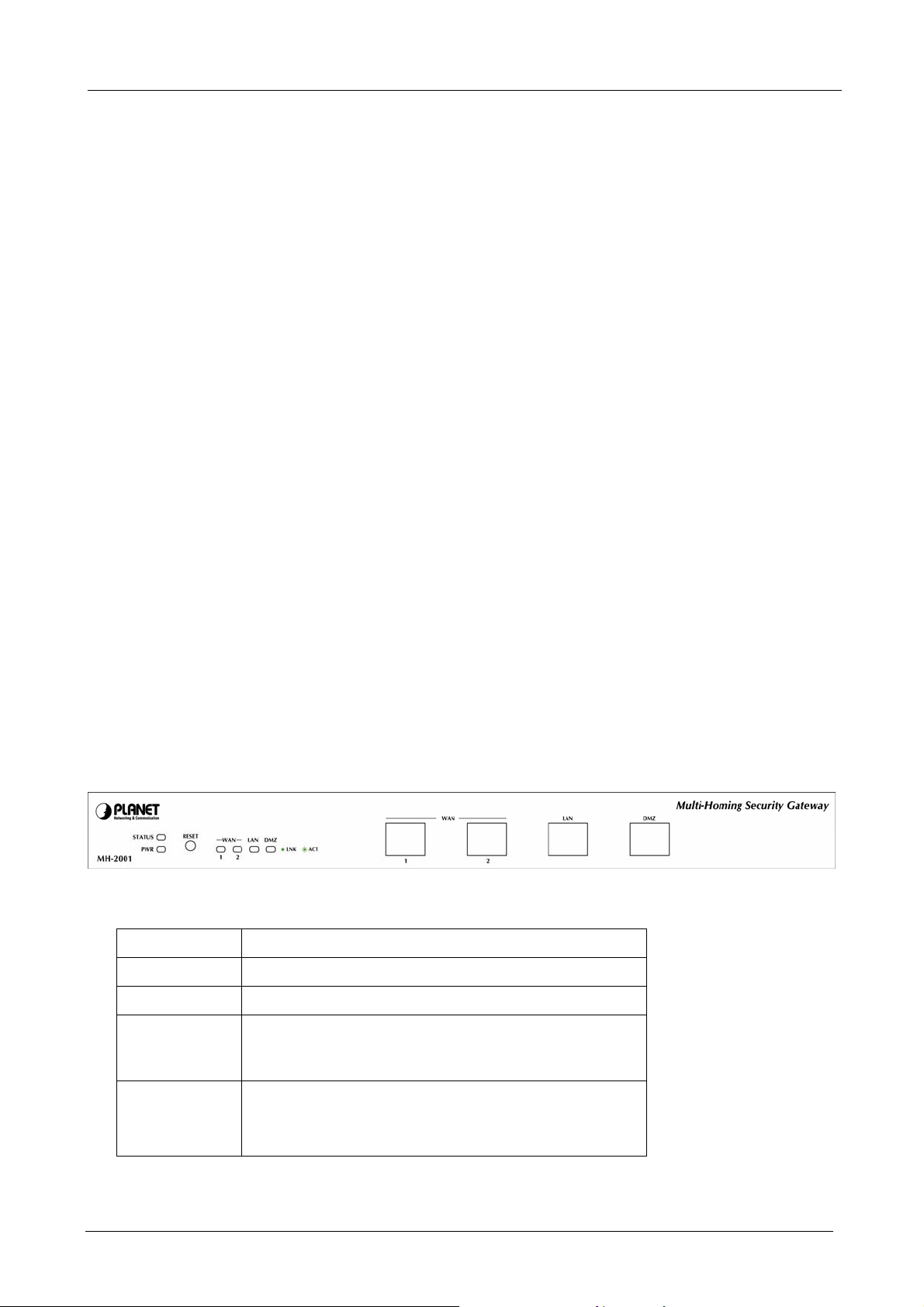
1.3 MH-2001 Front View
MH-2001 Front Panel
LED / Button Definition
LED / Button Description
Reset Button Press this button to restore factory default setting.
PWR Power is supplied to this device.
STATUS Blinks to indicate this devise is being turned on and
booting. Af ter four minutes, this LED indicator will stop
blinking, it means this device is now ready to use.
WAN1, WAN2,
LAN, DMZ
Steady on indicates the port is conn ected to other
network device.
Blink to indicates there is traffic on the port
- 2 -
Page 9
MH-2001 Multi-Homing Security Gateway User’s Manual
- Port definition
Port Description
WAN1, WAN2 Connect to your xDSL/Cable modem or other Internet
connection devices
LAN Connect to your local PC, switch or other local network
device
DMZ Connect to your server or other network device
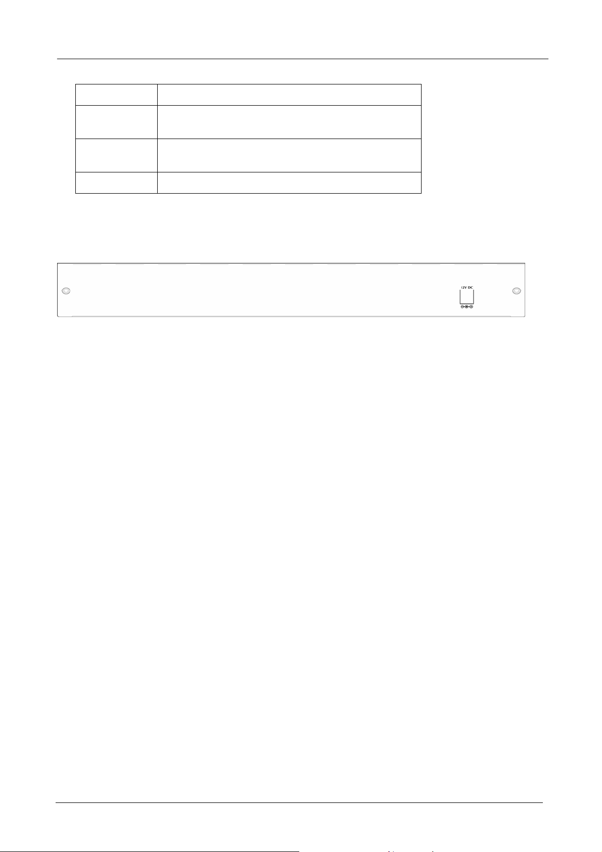
1.4 MH-2001 Rear Panel
MH-2001 Rear Panel
DC Power: connect one end of the power supply to this port, the other end to the electrical wall outlet.
- 3 -
Page 10

MH-2001 Multi-Homing Security Gateway User’s Manual
1.5 Specification
Product Multi-Homing Security Gateway
Model MH-2001
Hardware
Ethernet
Button Reset button for reset to factory default setting
Software
Management
Network Connection
Routing Protocol
Outbound Load Balancing
Firewall
VPN Tunnels
LAN
WAN
DMZ
1 x 10/100Mbps RJ-45
2 x 10/100Mbps RJ-45
1 x 10/100Mbps RJ-45
Web
DMZ_NAT, DMZ_Transparent, NAT
Static Route, RIPv2
Policy-based routing
Load-balancing by Round-Robin, traffic, session, packet, Source IP and
Destination IP
Policy-based firewall rule with schedule
NAT/ NAPT
SPI firewall
Prevention of SYN attack, ICMP Flood, UDP flood, Ping of Death, Tear Drop,
IP Spoofing, IP route, Port Scan and Land attack
200/100
(Configure/Connection)
VPN Functions
Content Filtering
Bandwidth Management
User authentication
Accounting Report
Log and Alarm
Statistics
Others
PPTP, IPSec
DES, 3DES and AES encrypting
SHA-1 / MD5 authentication algorithm
Remote access VPN (Client-to-Site) and Site to Site VPN
URL blocking, Script blocking (Pop up, Java Applet, cookies and Active X)
IM blocking (MSN, Yahoo Messenger, ICQ, QQ and Skype)
P2P blocking (eDonkey, Bit Torrent and WinMX)
Download and Upload blocking
Policy-based bandwidth management
Guarantee and maximum bandwidth with 3 priority levels
Classify traffics based on IP, IP subnet, TCP/UDP port
Built-in user database with up to 200 entries
Radius, POP3 authentication support
Outbound/Inbound accounting report statistics by Source IP, Destination IP
and Service
Log and alarm for event and traffic
Log can be saved from web, sent by e-mail or sent to syslog server
Traffic statistic for interface (WAN 1/2) and policies
Graphic display
Record up to 30 days
Firmware Upgradeable through Web
Configuration Backup and Restore through Web
Dynamic DNS
NTP support
DHCP server
Multiple NAT and multiple DMZ (mapped IP) support
Server load balancing
- 4 -
Page 11

MH-2001 Multi-Homing Security Gateway User’s Manual
Chapter 2: Hardware Installation
2.1 Installation Requirements
Before installing MH-2001, make sure your network meets the following requirements.
- Mechanical Requirements
MH-2001 is installed between your Internet connection and local area network. You can place it on the
table or rack, and locate the unit near the power outlet.
- Electrical Requirements
MH-2001 is a power-required device, which means, it will not work until it is powered. If your network PCs
will need to transmit data all the time, please consider use an UPS (Uninterrupted Power Supply) for your
MH-2001. It will prevent you from network data loss. In some area, installing a surge suppression device
may also help to protect your device from being damaged by unregulated surge or current to the MH-2001.
- Network Requirements
In order for MH-2001 to secure your network traffic, the traffic must pass through the device at a useful
point in a network. In most situations, MH-2001 should be placed behind the Internet connection device.
- 5 -
Page 12
MH-2001 Multi-Homing Security Gateway User’s Manual
2.2 Operation Mode
MH-2001 DMZ port supports three operation modes, Disable, NAT and Transparent. In Disable mode, the
DMZ port is not active. In transparent mode, MH-2001 works as proxy with forward DMZ packet to WAN
and forward WAN packet to DMZ. The DMZ and WAN side IP addresses are in the same subnet. In NAT
mode, DMZ side user will share one public IP address of WAN port to make Internet connection. Please
find the following two pictures for example.
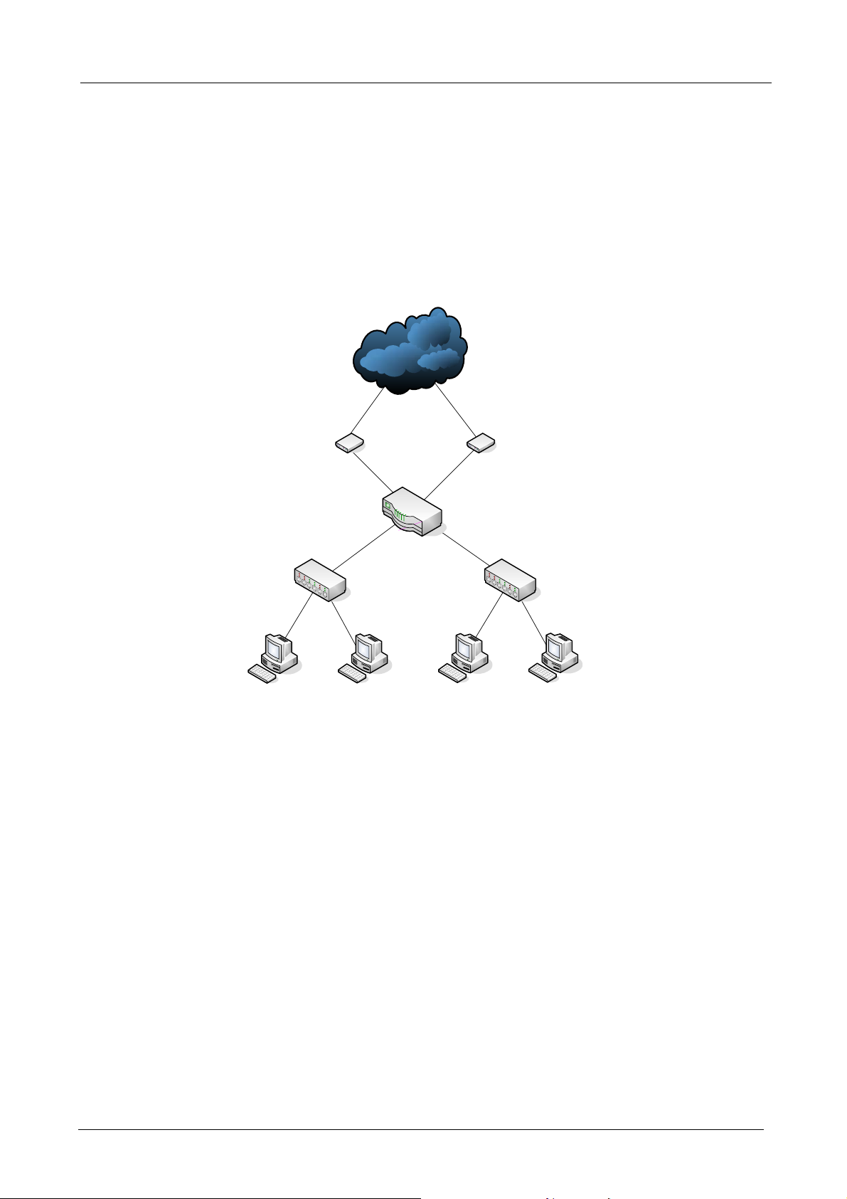
2.2.1 Transparent Mode Connection Example
Internet
ADSL / Cable
LAN
192.168.1.1
255.255.255.0
LAN PC1
192.168.1.2
ISP1
Modem
WAN1
61.11.11.11
LAN PC2
192.168.1.3
WAN2
62.22.22.22
MH-2001
DMZ PC1
61.11.11.12
ISP2
ADSL / Cable
Modem
DMZ Transparent
DMZ PC2
61.11.11.13
To WAN1
The WAN1 and DMZ side IP addresses are on the same subnet. This application is suitable if you have a
subnet of IP addresses and you do not want to change any IP configuration on the subnet.
- 6 -
Page 13
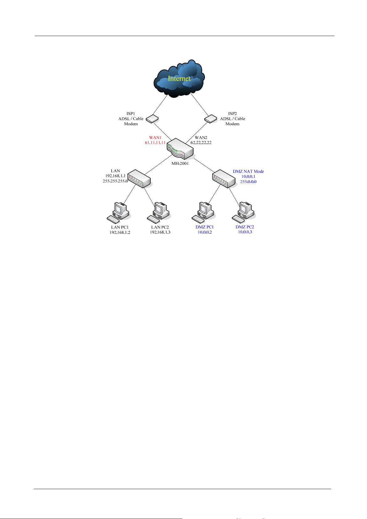
2.2.2 NAT Mode Connecting Example
MH-2001 Multi-Homing Security Gateway User’s Manual
DMZ and WAN1 IP addresses are on the different subnet. This provides higher security level then
transparent mode.
- 7 -
Page 14
MH-2001 Multi-Homing Security Gateway User’s Manual
Chapter 3: Getting Started
3.1 Web Configuration
STEP 1:
Connect the Administrator’s PC and the LAN port of MH-2001 to a hub or switch. Make sure there is a link
light on the hub/switch for both connections. MH-2001 has an embedded web server used for management
and configuration. Use a web browser to display the configurations of MH-2001 (such as Internet Explorer
4(or above) or Netscape 4.0(or above) with full java script support). The default IP address of MH-2001 is
192.168.1.1 with a subnet mask of 255.255.255.0. Therefore, the IP address of the Administrator PC must be
in the range between 192.168.1.2– 192.168.1.254
If the company’s LAN IP Address is not subnet of 192.168.1.0, (i.e. LAN IP Address is 172.16.0.1), then the
Administrator must change his/her PC IP address to be within the same range of the LAN subnet. Reboot
the PC if necessary.
By default, MH-2001 is shipped with its DHCP Server function enabled. This means the client computers on
the LAN network including the Administrator PC can set their TCP/IP settings to automatically obtain an IP
address from the device.
The following table is a list of private IP addresses. These addresses may not be used as a WAN IP address.
10.0.0.0 ~ 10.255.255.255
172.16.0.0 ~ 172.31.255.255
192.168.0.0 ~ 192.168.255.255
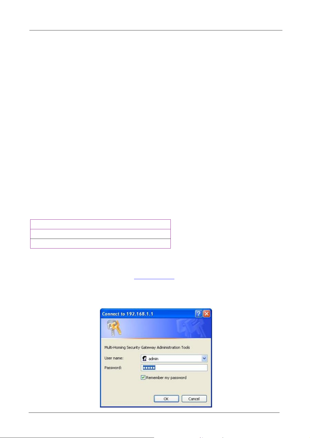
STEP 2:
Once the Administrator PC has an IP address on the same network as the Multi-Homing Security Gateway,
open up an Internet web browser and type in http://192.168.1.1
A pop-up screen will appea r and prompt for a username and p assword. A username and password is required
to connect to MH-2001. Enter the default login username and password of Administrator (see below).
Username: admin
Password: admin
in the address bar.
Click OK.
- 8 -
Page 15
MH-2001 Multi-Homing Security Gateway User’s Manual
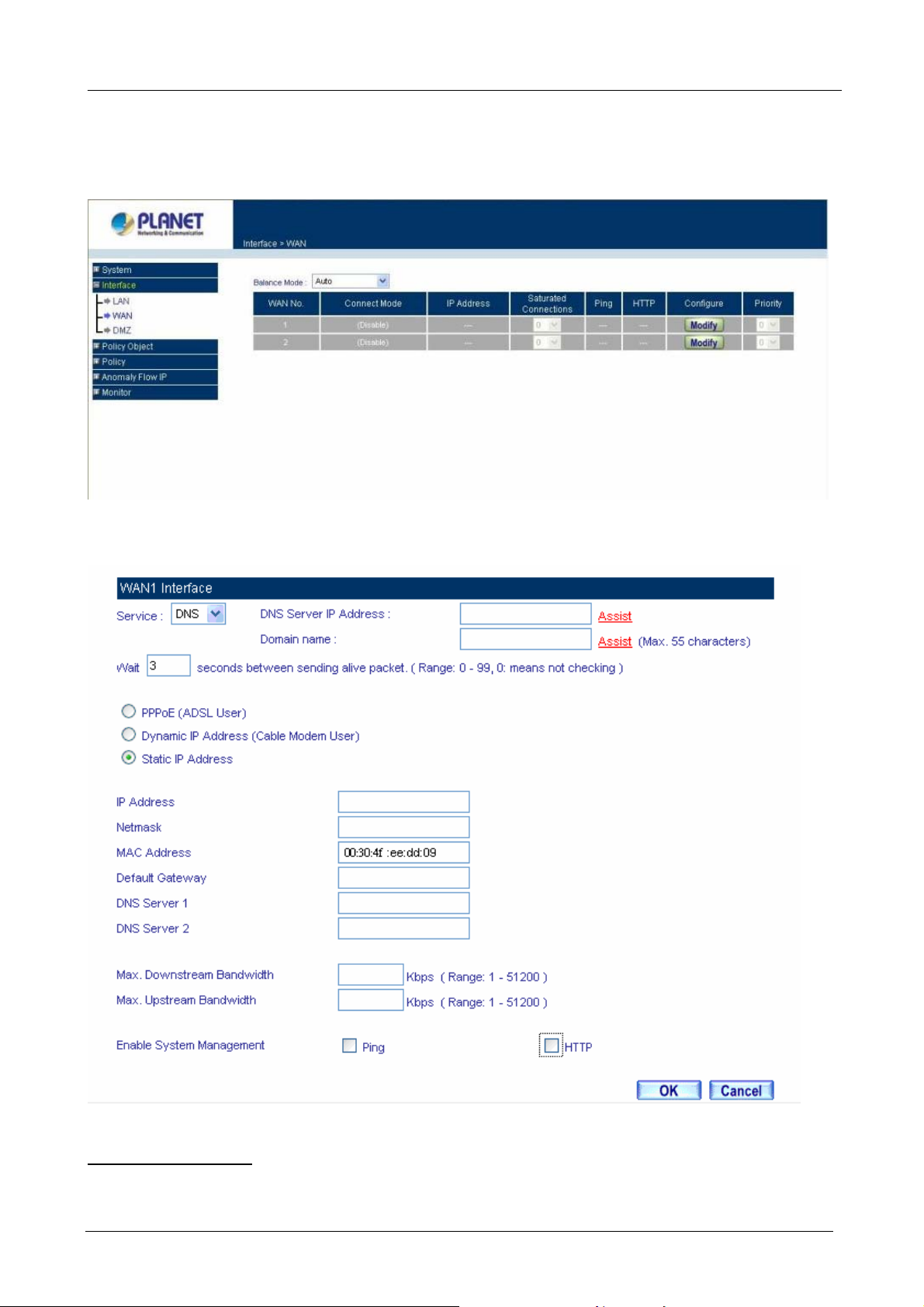
3.2 Configure WAN 1 interface
After entering the username and password, MH-2001 WebUI screen will display. Select the Interface tab on
the left menu. Click on WAN from the sub-fun ction list, and a sub-function list will be displayed.
Click Modify button to configure WAN NO. 1 and the following page will be displayed.
Alive Indicator Site IP:
Service: ICMP You can select an IP address by Assist, or type an IP address manually.
This feature is used to ping an address for detecting WAN connection status.
- 9 -
Page 16

MH-2001 Multi-Homing Security Gateway User’s Manual
Service: DNS You can select a DNS IP and Domain name by Assist, or type the related data manually.
PPPoE (ADSL User):
This option is for PPPoE users who are required to enter a username and password in
order to connect.
Username: Enter the PPPoE username provided by the ISP.
Password: Enter the PPPoE password provided by the ISP.
IP Address provided by ISP:
Dynamic: Select this if the IP address is automatically assigned by the ISP.
Fixed: Select this if you were given a static IP address. Enter the IP address that is given to you by
your ISP.
Max. Upstream/Downstream Bandwidth: The bandwidth provided by ISP.
Service-On-Demand:
The PPPoE connection will automatically disconnect after a length of idle time (no activities). Enter in
the amount of idle minutes before disconnection. Enter ‘0’ if you do not want the PPPoE connection to
disconnect at all.
For Dynamic IP Address (Cable Modem User):
This option is for users who are automatically assigned an
IP address by their ISP, such as cable modem users. The following fields apply:
MAC Address: This is the MAC Address of the device. Some ISPs require specified MAC add ress. If the
required MAC address is your PC’s, click Clone MAC Address.
Hostname: This will be the name assign to the device. Some cable modem ISP assigns a specific
hostname in order to connect to their network, please enter the hostname here. If not
required by your ISP, you do not have to enter a hostname.
Domain Name: You can specify your own domain name or leave it blank.
User Name: The user name is provided by ISP.
Password: The password is provided by ISP.
Max. Upstream/Downstream Bandwidth: The bandwidth provided by ISP.
For Static IP Address:
This option is for users who are assigned a static IP Address from their ISP. Your ISP
will provide all the information needed for this section such as IP Address, Netmask, Gateway, and DNS.
IP Address: Enter the static IP address assign ed to you by your ISP. This will be the public IP address of
the WAN 1 port of the device.
Netmask: This will be the Netmask of the WAN 1 network. (i.e. 255.255.255.0)
Default Gateway: This will be the Gateway IP address.
Domain Name Server (DNS): This is the IP Address of the DNS server.
Max. Upstream/Downstream Bandwidth: The bandwidth provided by ISP.
Ping:
Select this to allow the WAN network to ping the IP Address of MH-2001 This will allow people from the
Internet to be able to ping MH-2001 WAN IP. If set to enable, the device will respond to echo request packets
from the WAN network.
- 10 -
Page 17
MH-2001 Multi-Homing Security Gateway User’s Manual
HTTP: Select this to allow the device WebUI to be accessed from the W AN network. This will allow the W ebUI
to be configured from a user on the Internet. Keep in mind that the device always requires a username and
password to enter the WebUI.
3.3 Configure WAN 2 interface
If you want to connect WAN 2 to another ISP connection, click Modify button of W AN No. 2 then repeat abov e
procedures to setup.
3.4 Configure DMZ interface
Depends on your network requirement, you can disable the DMZ port, make DMZ port transparent to WAN 1 or
enable NAT function on it.
To configure the DMZ port, select the Interface tab on the left menu, then click on DMZ, the following page is
shown.
Please refer to Section 2.2 for select the mode you need and configure relative IP parameters.
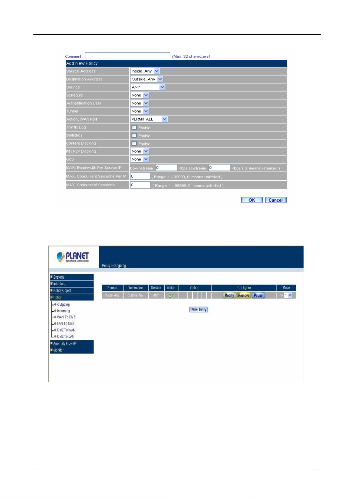
3.5 Configure Policy
STEP 1:
Click on the Policy tab from the main function menu, and then click on Outgoing (LAN to WAN) from the
sub-function list.
STEP 2:
Click on New Entry button.
STEP 3:
When the New Entry option appears, enter the following configuration:
Source Address – select “Inside_Any”
Destination Address – select “Outside_Any”
Service - select “ANY”
Action - select “Permit, ALL”
Click on OK to apply the changes.
- 11 -
Page 18
MH-2001 Multi-Homing Security Gateway User’s Manual
STEP 4:
The configuration is successful when the screen below is displayed.
Please make sure that all the computers that are connected to the LAN port have their Default Gateway IP
Address set to MH-2001’s LAN IP Address (i.e. 192.168.1.1). At this point, all the computers on the LAN
network should gain access to the Internet immediately. If MH-2001 filter function is required, please refe r to
the Policy section in chapter 7.
- 12 -
Page 19
MH-2001 Multi-Homing Security Gateway User’s Manual
Chapter 4: System
MH-2001 Administration and monitoring configuration is set by the System Administrator. The System
Administrator can add or modify System settings and monitoring mode. The sub Administrators can only read
System settings but not modify them. In System, the System Administrator can:
1. Add and change the sub Administrator’s names and passwords;
2. Back up all MH-2001 settings into local files;
3. Set up alerts for Hackers invasion.
“System” is the managing of settings such as the privileges of packets that pass through MH-2001 and
monitoring controls. Administrators may manage, monitor, and configure MH-2001 settings. All configurations
are “read-only” for all users other than the Administrator; those users are not able to change any settings for
MH-2001.
4.1 Administration
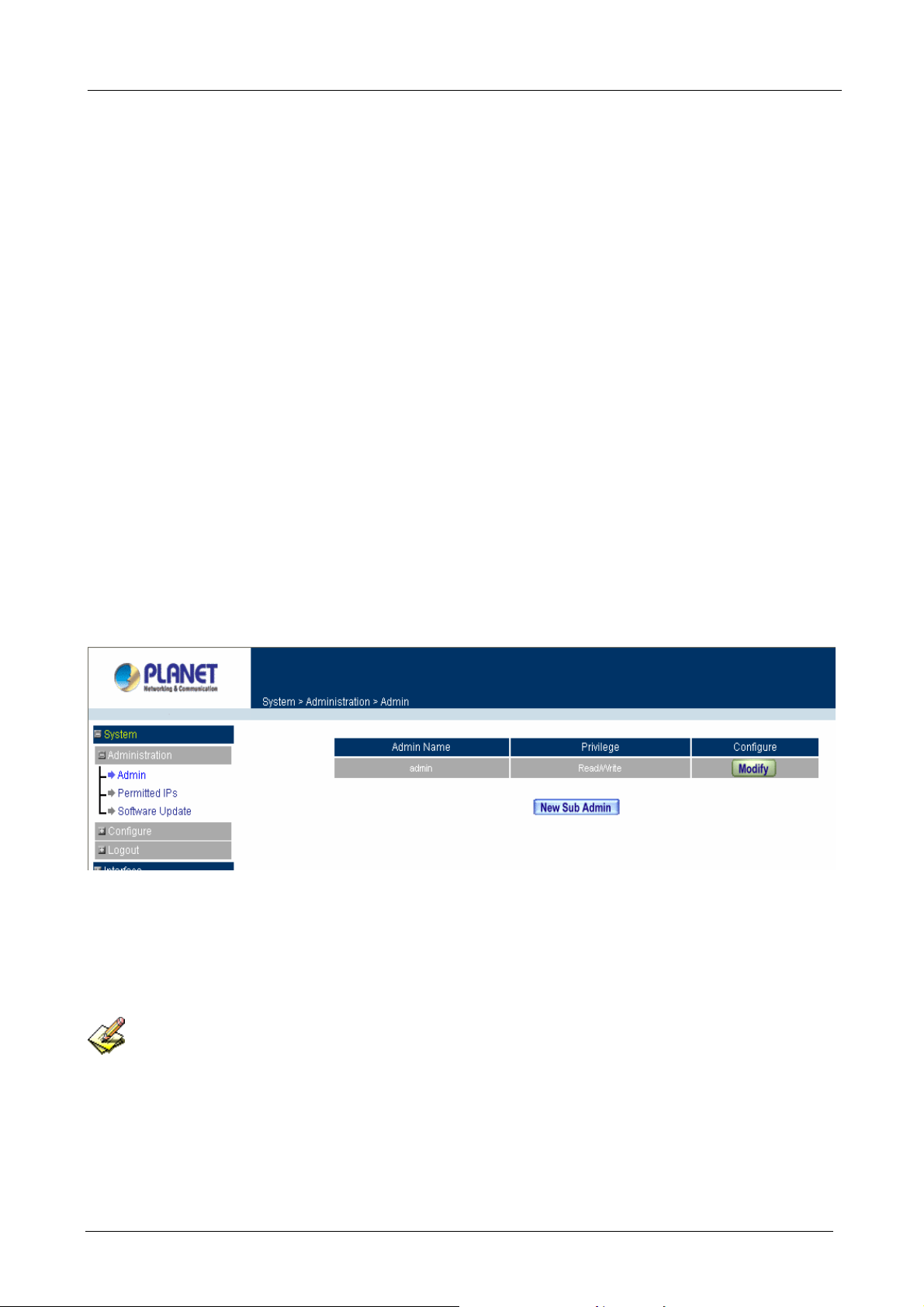
4.1.1 Admin
Click the System/Administration/Admin on the left menu, and the list of Administrato rs will display as bel ow.
Define the required fields of Administrator
Admin Name:
The username of Administrators and Sub Administrator for the MH-2001. The admin user name cannot
be removed; and the sub-admin user can be removed or configure.
The default Account: admin; Password: admin
Privilege:
The privileges of Administrators (Admin or Sub Admin). The username of the main Administrator is
Administrator with reading / writing privilege. Administrator also can change the system setting, log
system status, and to increase or delete sub-administrator . Sub-Admin may be created by the Admin by
- 13 -
Page 20
MH-2001 Multi-Homing Security Gateway User’s Manual
clicking
system setting value.
Configure:
Click Modify to change the “Sub-Administrator’s” password or click Remove to delete a “Sub
Administrator.”
New Sub Admin
. Sub Admin have only read and monitor privilege and cannot change any
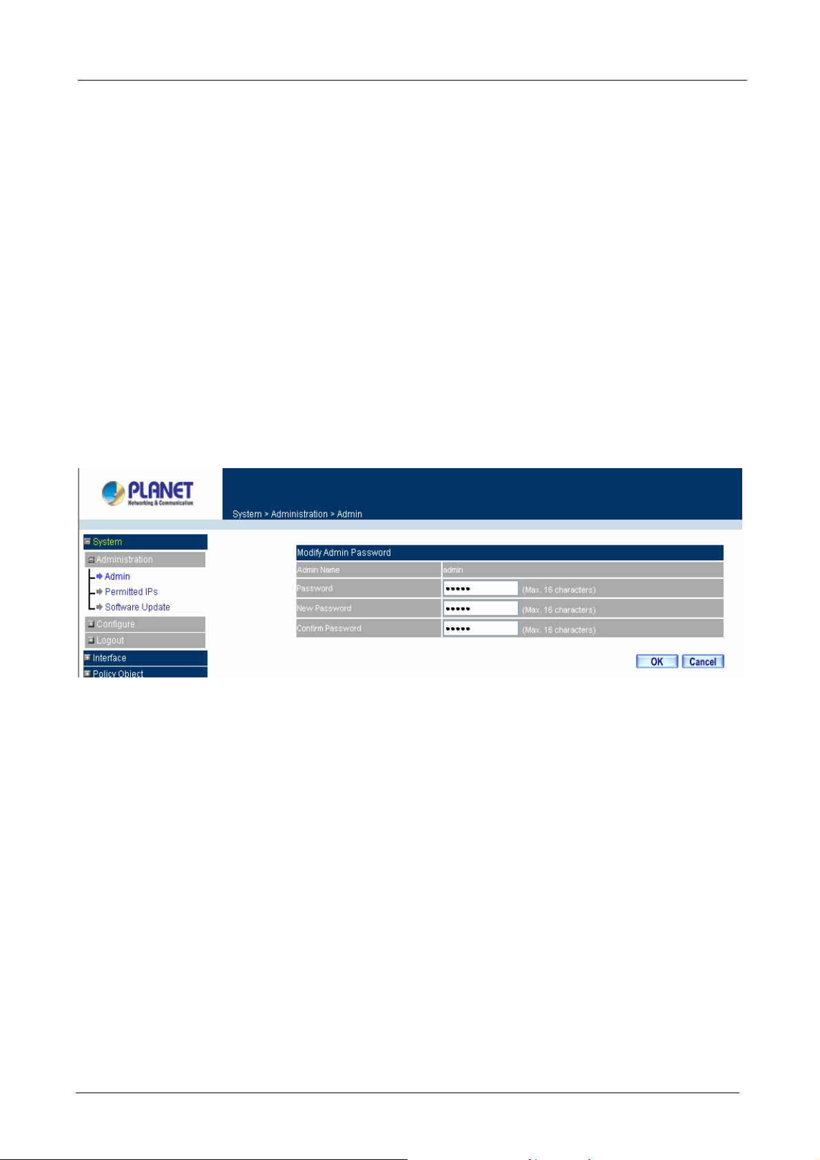
Changing the Main/Sub-Administrator’s Password
Step 1. The Modify Administrator Password window will appear. Enter in the required information:
Password: enter original password.
New Password: enter new password
Confirm Password: enter the new password again.
Step 2. Click OK to confirm password change or click Cancel to cancel it.
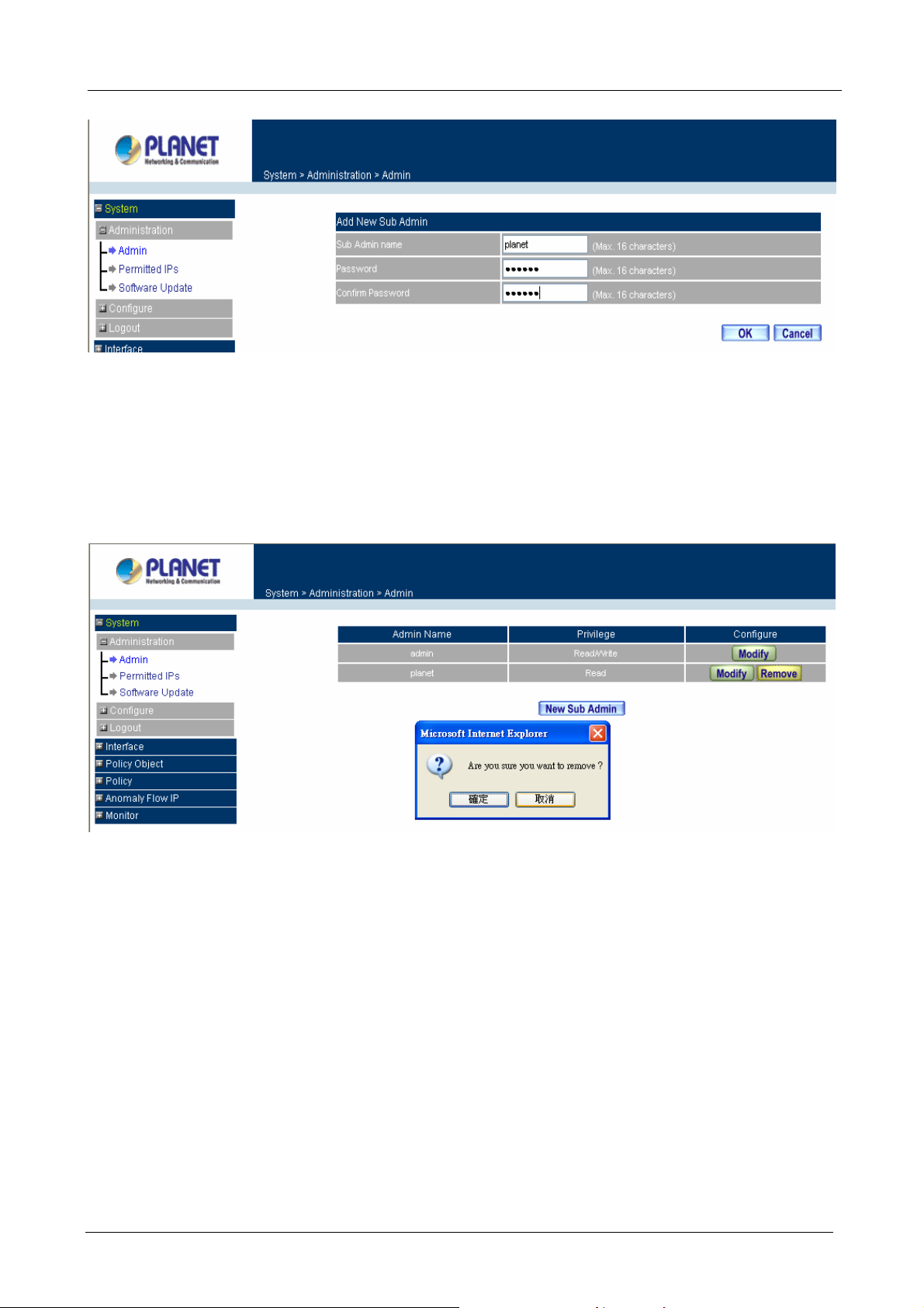
Adding a new Sub Administrator
Step 1. In the Add New Sub Administrator window:
Sub Admin Name: enter the username of new Sub Admin.
Password: enter a password for the new Sub Admin.
Confirm Password: enter the password again.
Step 2. Click OK to add the user or click Cancel to cancel the addition.
- 14 -
Page 21
MH-2001 Multi-Homing Security Gateway User’s Manual
Removing a Sub Administrator
Step 1. In the Administration table, locate the Administrator name you want to edit, and click on the
Remove option in the Configure field.
Step 2. The Remove confirmation pop-up box will appear. Click OK to remove that Sub Admin or click
Cancel to cancel.
- 15 -
Page 22
MH-2001 Multi-Homing Security Gateway User’s Manual
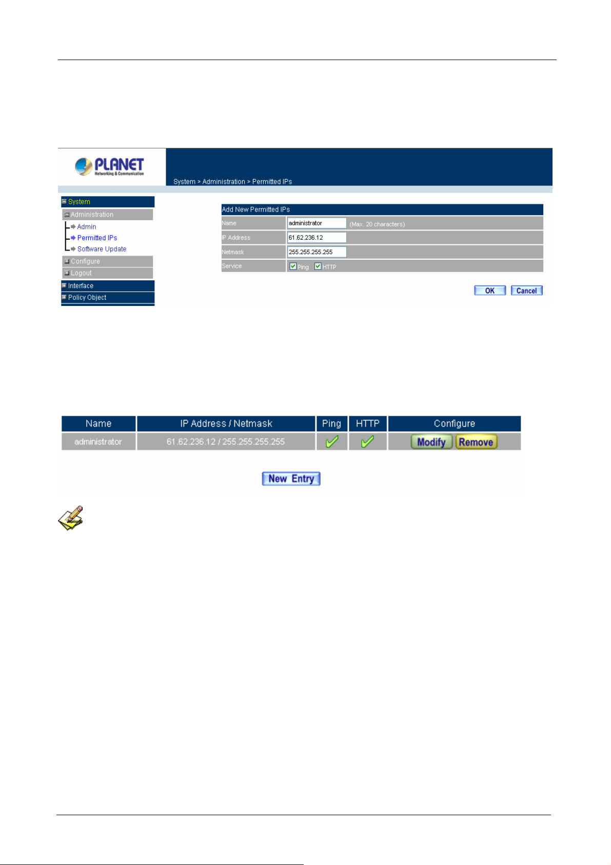
4.1.2 Permitted IPs
Add Permitted IPs
STEP 1﹒Add the following setting in Permitted IPs of Administration:
Name: Enter a new name
IP Address: Enter a IP address you want to permitted
Netmask: Enter the Netmask( 255.255.255.255 mean s a host)
Service: Select Ping and HTTP
Click OK
Complete add new permitted IPs
To make Permitted IPs be effective, it must cancel the Ping and HTTP selection in the WebUI of
MH-2001 that Administrator enter. (LAN, WAN, or DMZ Interface)
Before canceling the HTTP selection of Interface, must set up t he Permitted IPs first, otherwise, it would
cause the situation of cannot enter WebUI by appointed Interface.
- 16 -
Page 23
MH-2001 Multi-Homing Security Gateway User’s Manual
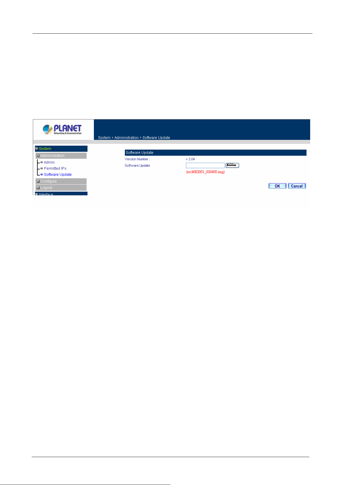
4.1.3 Software Update
Under Software Update, the admin may update the device’s software with newer software.
You may acquire the current version number of software in Version Number. Administrators may visit
distributor’s web site to download the latest version and save it in server’s hard disc.
Step 1. Click Browse to select the latest version of Software.
Step 2. Click OK to update software.
NOTE: It takes three minutes to update the software. The system will restart automatically after updating the
software.
- 17 -
Page 24
MH-2001 Multi-Homing Security Gateway User’s Manual
4.2 Configure
The Configure is according to the basic setting of theMH-2001. In this chapter the definition is Setting,
Date/Time, Multiple Subnet, Route Table, DHCP, Dynamic DNS, Hosts Table, and Language settings.
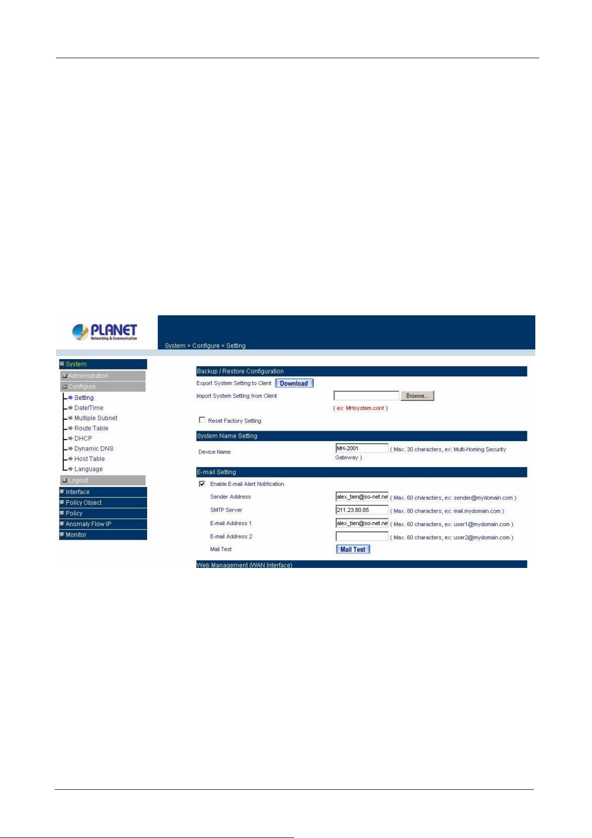
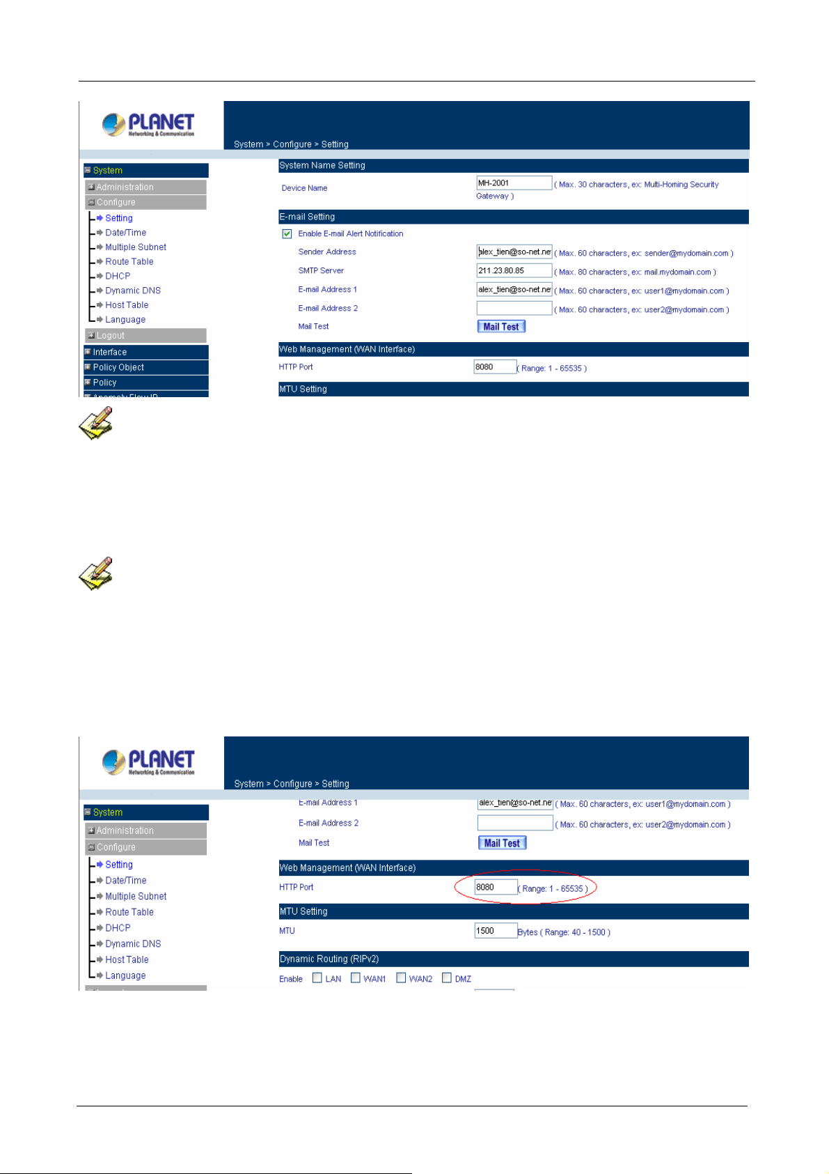
4.2.1 Setting
The Administrator may use this function to backup, restore MH-2001 configurations or restore MH-2001 back
to default factory settings. You can also set general setting like device’s name, E-mail setting and HTTP port
on it.
Entering the Settings window
Click Setting in the System/configure menu to enter the Settings window. MH-2001 Configuration
settings will be shown on the screen.
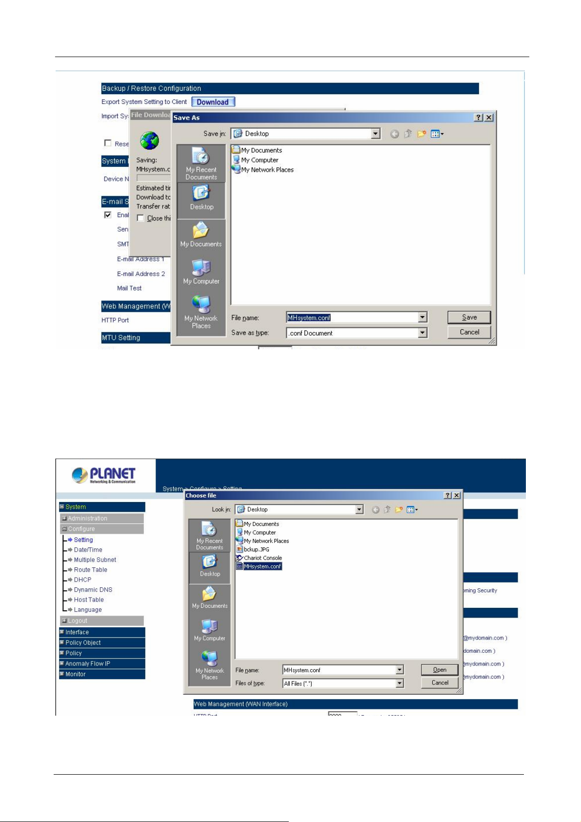
Exporting MH-2001 settings
Step 1. Under Backup/Restore Configuration, click on the Download button next to Export System
Settings to Client.
Step 2. When the File Download pop-up window appears, choose the destination place to save the
exported file.
- 18 -
Page 25
MH-2001 Multi-Homing Security Gateway User’s Manual
Importing MH-2001 settings
Under Backup/Restore Configuration, click on the Browse button next to Import System Settings. When
the Choose File pop-up window appears, select the file which contains the saved MH-2001 Settings, then
click OK.
Click OK to import the file into MH-2001 or click Cancel to cancel importing.
- 19 -
Page 26
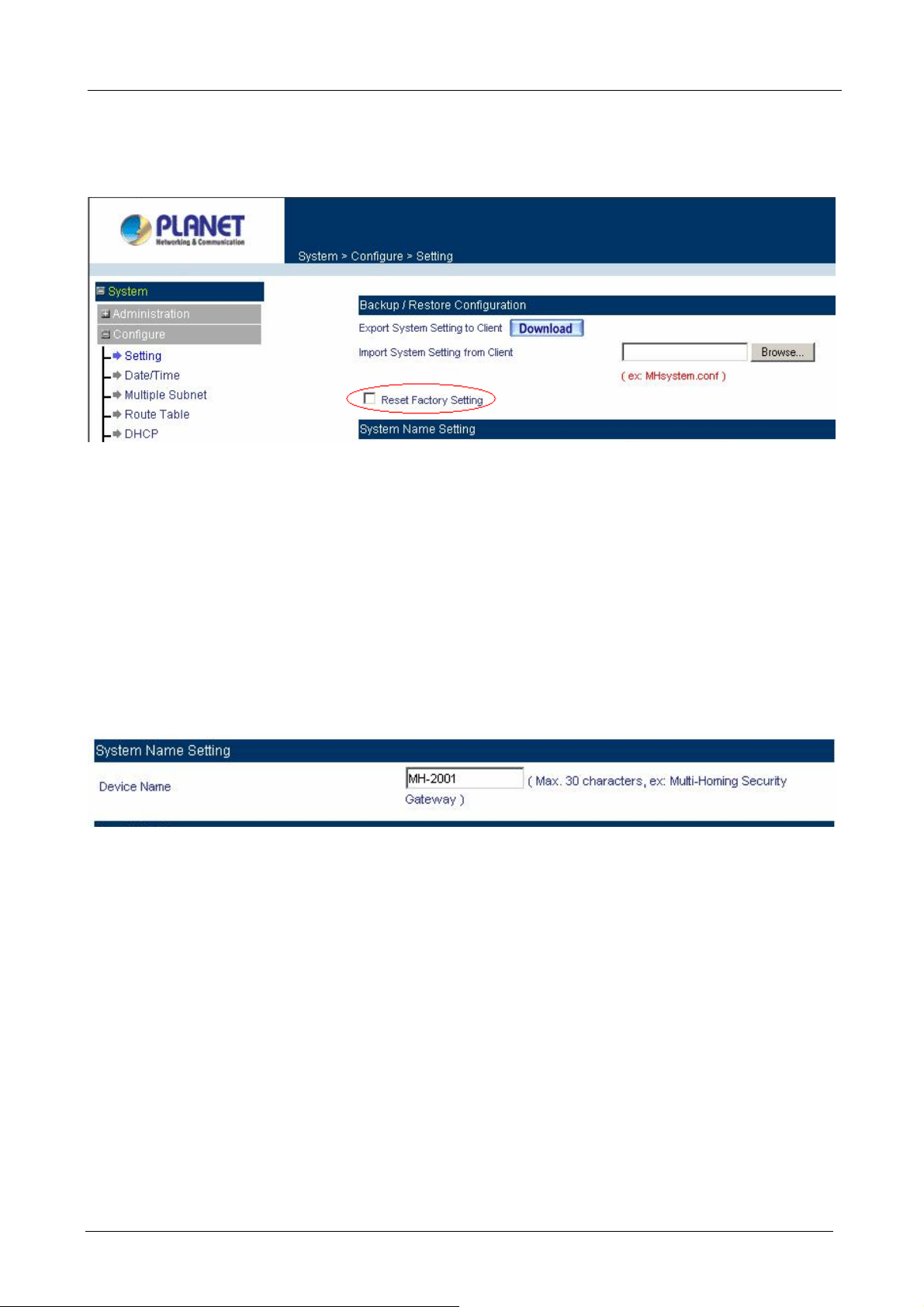
Restoring Factory Default Settings
Step 1. Select Reset Factory Settings.
Click OK at the bottom-right of the screen to restore the factory settings.
MH-2001 Multi-Homing Security Gateway User’s Manual
System Name Setting
Step 1. You can modify your device name. Enter the new name in the field.
Step 2. Click OK at the bottom-right of the screen.
Enabling E-mail Alert Notification
Step 1. Select Enable E-mail Alert Notification under E-Mail Settings. This function will enable the
MH-2001 to send e-mail alerts to the System Administrator when the network is being attacked
by hackers or when emergency conditions occur.
Step 2. SMTP Server IP: Enter SMTP server’s IP address.
Step 3. E-Mail Address 1: Enter the first e-mail address to receive the alarm notification.
Step 4. E-Mail Address 2: Enter the second e-mail address to receive the alarm notification. (Optional)
Step 5. Click OK on the bottom-right of the screen to enable E-mail alert notification.
- 20 -
Page 27
MH-2001 Multi-Homing Security Gateway User’s Manual
Click on Mail T est to test if E-mail Address 1 and E-mail Address 2 can receive the Alert Notification
correctly.
Web Management (WAN Interface)
The administrator can change the port number used by HTTP port anytime. (Remote WebUI management)
After HTTP port has changed, if the administrator want to enter WebUI from WAN, will have to change
the port number of browser. (For example: http://61.62.108.172:8080)
Step 1. Set Web Management (WAN Interface). Enter the new port number used by HTTP port.
( Range 1 – 65535 )
Step 2. Click OK at the bottom-right of the screen.
- 21 -
Page 28
MH-2001 Multi-Homing Security Gateway User’s Manual
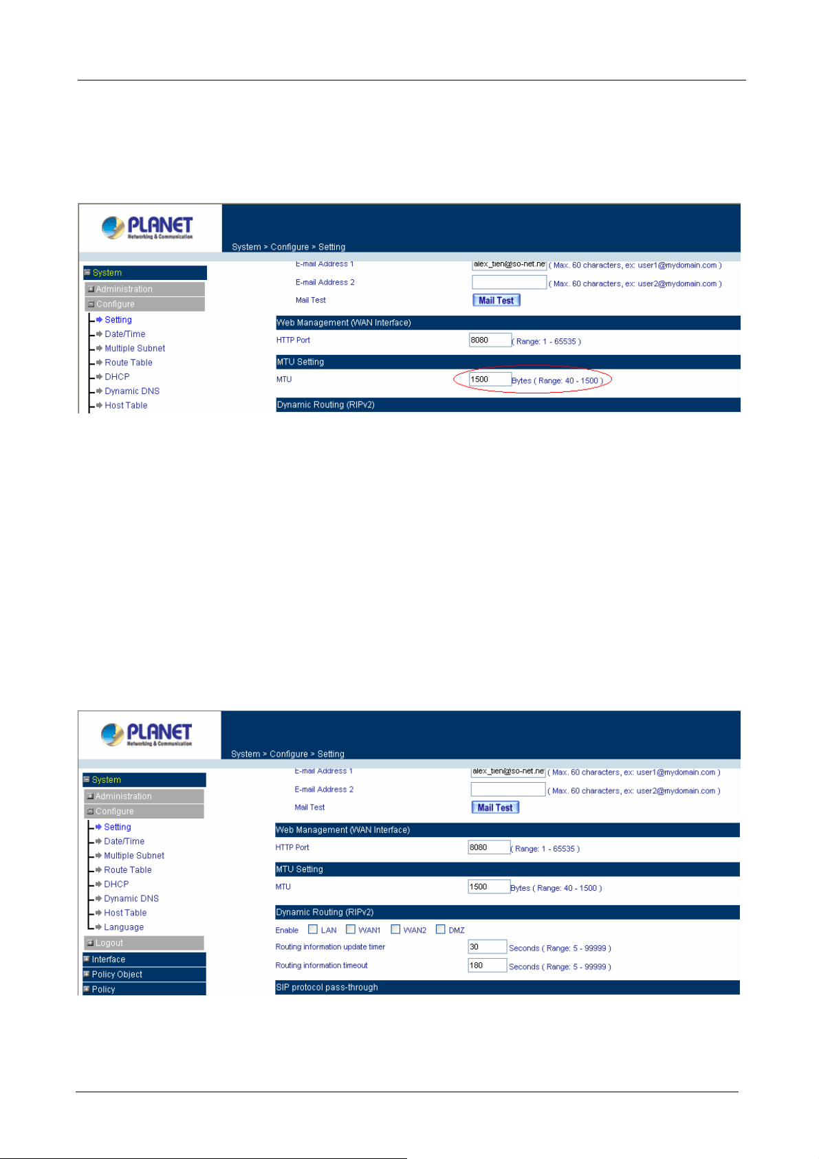
MTU (set networking packet length)
The administrator can modify the networking packet length.
Step 1. MTU Setting. Modify the networking packet length. ( Range 40 – 1500 )
Step 2. Click OK at the bottom-right of the screen.
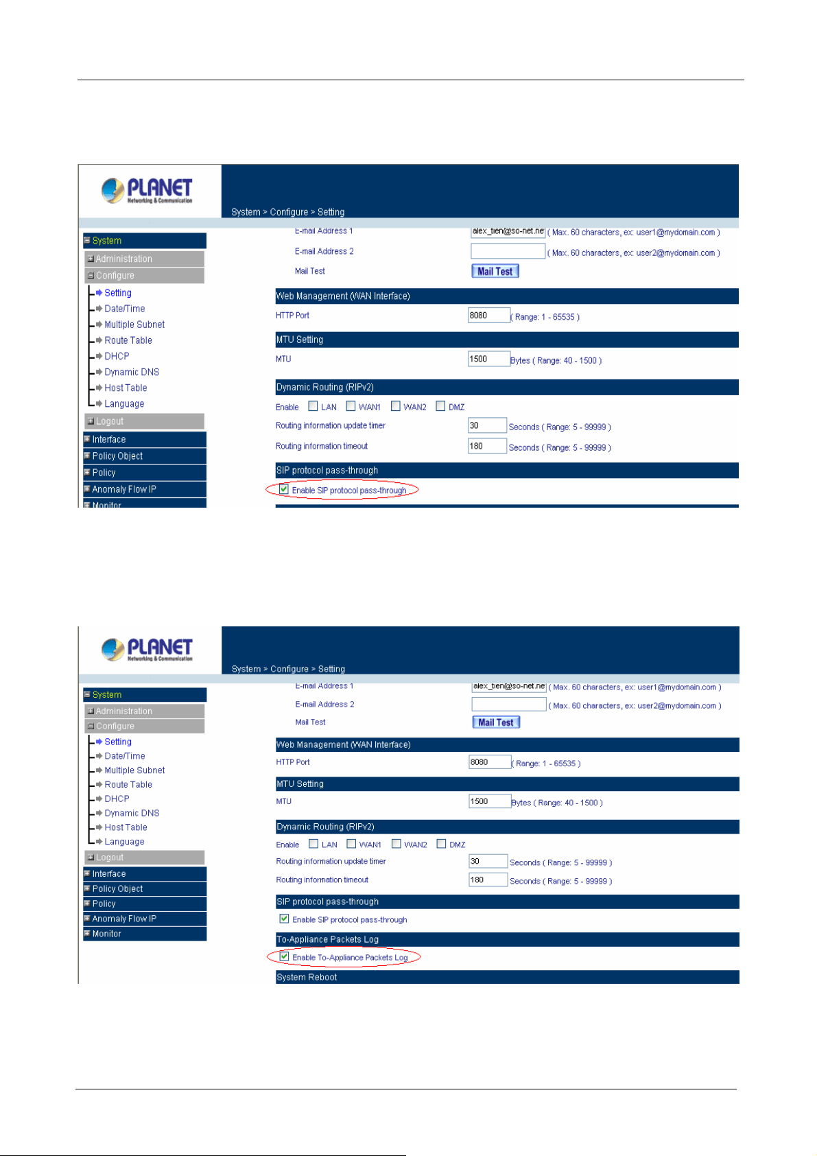
Dynamic Routing (RIPv2)
Enable Dynamic Routing (RIPv2), MH-2001 will switch the routing information of RIP. The routers which
support RIP can connect automatically. You can choose to enable LAN, WAN1, WAN2 or DMZ interface to
allow RIP protocol supporting.
Routing information update timer: MH-2001 will send out the RIP protocol in a period of time to update the
routing table, the default timer is 30 seconds.
Routing information timeout: If MH-2001 does not receive the RIP protocol fro m the other router in a peri od
of time, MH-2001 will cut off the routing automatically until it receives RIP protocol again. The default timer is
180 seconds.
- 22 -
Page 29
MH-2001 Multi-Homing Security Gateway User’s Manual
SIP protocol pass-through
Select this option to the device’s SIP protocol pass-through. Once this function is enabled, the SIP
packets will be allowed to pass-throug h via MH-2001.
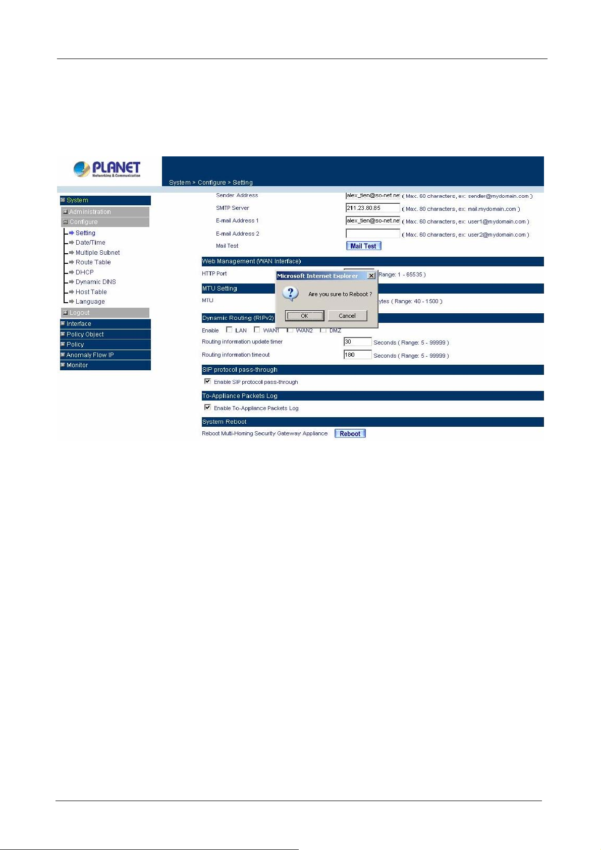
To-Appliance Packets Log
Select this option to the device’s To-Appliance Packets Log. Once this function is enabled, every packet
to this appliance will be recorded for system administrator to trace.
- 23 -
Page 30
MH-2001 Multi-Homing Security Gateway User’s Manual
System Reboot
Once this function is enabled, MH-2001 will be rebooted.
Click Reboot. The confirmation pop-up box will appear. Click OK to restart MH-2001 or click Cancel to
discard changes
4.2.2 Date/Time
Synchronizing the MH-2001 with the System Clock
Administrator can configure MH-2001’s date and time by either syncing to an Internet Network Time Server
(NTP) or by syncing to your computer’s clock.
Follow these steps to sync to an Internet T i me Server
Step 1. Enable synchronization by checking the box.
Step 2. Click the down arrow to select the offset time from GMT.
Step 3. Enter the Server IP Address or Server name with which you want to synchronize.
Step 4. Update system clock every 120 minutes You can set the interval time to synchronize with
outside servers. If you set it to 0, it means the device will not synchronize automatically.
Follow this step to sync to your computer’s clock.
Step 1. Click on the Sync button. Click OK to apply the setting or click Cancel to disca rd changes.
- 24 -
Page 31

MH-2001 Multi-Homing Security Gateway User’s Manual
The value of Set Offset From GMT and Server IP / Name can be looking for from Assist.
4.2.3 Multiple Subnet
NAT mode
Multiple Subnet allows local port to set multiple subnet works and connect with the internet through different
WAN 1 IP Addresses.
For instance: The lease line of a com pany applies several real IP Addresses 168.85.88.0/24, and the
company is divided into R&D department, service, sales de partment, procurement department, accounting
department, the company can distinguish each department by different subnet works for the purpose of
convenient management. The settings are as the following:
1. R&D department sub-network: 192.168.1.11/24(LAN ) ÅÆ 168.85.88.253(WAN 1)
2. Service department sub-network: 192.168.2.11/24(LAN ) ÅÆ 168.85.88.252 (WAN 1)
3. Sales department sub-network: 192.168.3.11/24(LAN ) ÅÆ 168.85.88.251(WAN 1)
4. Procurement department sub-network: 192.168.4.11/24(LAN ) ÅÆ 168.85.88.250(WAN 1)
5. Accounting department sub-network: 192.168.5.11/24(LAN ) ÅÆ 168.85.88.249(WAN 1)
The first department(R&D department) was set while setting interface IP, the other four ones have to be added
in Multiple Subnet, after completing the settings, each department use the different WAN IP Address to
connect to the internet. The settings of LAN computers on Service department are as the following
Service IP Address: 192.168.2.1
Subnet Mask: 255.255.255.0
Default Gateway: 192.168.2.11
The other departments are also set by groups, this is the function of Multiple Subnet.
- 25 -
Page 32

MH-2001 Multi-Homing Security Gateway User’s Manual
Multiple Subnet settings
Click Multiple Subnet under the System/Configure menu to enter Multiple Subnet window.
Multiple Subnet functions:
WAN Interface IP / Forwarding Mode: Display WAN Port IP Address and Forwarding Mode.
Alias IP of Interface / Netmask: Local Interface IP Address and subnet Mask.
Configure: Modify the settings of Multiple Subnet. Click Modify to modify the parameters of Multiple Subnet
or click Remove to delete settings.
Add a Multiple Subnet with NAT Mode:
Step 1: Click the New Entry button below to add Multiple Subnet.
Step 2: Interface: Select LAN or DMZ Interface which you want to add a Subnet.
Alias IP of LAN Interface: Enter Subnet Interface IP Address.
Netmask: Enter Subnet Interface Netmask.
WAN Interface IP: Add WAN 1 or WAN 2 IP.
Forwarding Mode: Select the NAT button to enable NA T mode.
Step 3: Click OK to add Multiple Subnet or click Cancel to discard changes.
Add a Multiple Subnet with Routing Mode:
Multiple Subnet allows local Interface to set Multiple Subnet Routing Mode and connect with the internet
through different WA N IP Addresses.
- 26 -
Page 33

MH-2001 Multi-Homing Security Gateway User’s Manual
For example, the leased line of a company applies several real IP Addresses 168.85.88.0/24 and the
company is divided into R&D, Customer Service, Sales, Procurement, and Accounting Department. The
company can distinguish each department by different sub-network for the purpose of convenient
management.
The settings are as the following:
1. R&D department: Alias IP of LAN interface - 168.85.88.1, Netmask: 255.255.255.192
2. Sales department: Alias IP of LAN interface - 168.85.88.65, Netmask: 255.255.255.192
3. Procurement department: Alias IP of LAN interface - 168.85.88.129, Netmask: 255.255.255.192
4. Accounting department: Alias IP of LAN interface - 168.85.88.193, Netmask: 255.255.255.192
Click Multiple Subnet under the System/Configure menu to enter Multiple Subnet window.
Multiple Subnet functions
WAN Interface IP / Forwarding Mode: Display WAN Port IP Address and Forwarding Mode which is NAT
Mode or Routing Mode.
Alias IP of Int. Interface / Subnet Mask: Local Interface IP Address and subnet Mask.
Modify: Modify the settings of Multiple Subnet. Click Modify to modify the parameters of Multiple Subnet or
click Remove to delete settings.
Adding a Multiple Subnet with Routing Mode
Step 1: Click the Add button below to add Multiple Subnet.
Step 2: Interface: Select LAN or DMZ Interface which you want to add a Subnet.
Alias IP of LAN Interface: Enter Subnet Interface IP Address.
Netmask: Enter Subnet Interface Netmask.
WAN Interface IP: Add WAN 1 or WAN 2 IP.
Forwarding Mode: Select the Routing button to enable Routing mode.
Step 3: Click OK to add Multiple Subnet or click Cancel to discard changes.
- 27 -
Page 34

MH-2001 Multi-Homing Security Gateway User’s Manual
4.2.4 Route Table
In this section, the Administrator can add static routes for the networks.
Entering the Route Table screen
Click Route Table under the System/Configure menu and the Route Table window will appear, in which
current route settings are shown.
Route Table functions
Interface: Destination network through the Interface, LAN, DMZ or WAN 1.
Destination IP: IP address of destination network.
NetMask: Netmask of destination network.
Gateway: Gateway IP address for connecting to destination network.
Configure: Modify or remove the settings in the route table.
Adding a new Static Route
Step 1. In the Route Table window, click the New Entry button.
Step 2. In the Add New Static Route window, enter new static route information.
Step 3. In the Interface pull-down menu, choose the Interface to connect (LAN, WAN1, DMZ).
Step 4. Click OK to add the new static route or click Cancel to cancel.
- 28 -
Page 35

MH-2001 Multi-Homing Security Gateway User’s Manual
4.2.5 DHCP
In this section, the Administrator can configure DHCP (Dynamic Host Configuration Protocol) settings for the
LAN and DMZ network.
Entering the DHCP window
Click DHCP under the System/Configure menu. The DHCP wi ndow app ears in whi ch current DHCP settings
are shown on the screen.
Dynamic IP Address functions
Subnet: LAN network’s subnet
NetMask: LAN network’s netmask
Gateway: LAN network’s gateway IP address
Broadcast: LAN network’s broadcast IP address
- 29 -
Page 36

MH-2001 Multi-Homing Security Gateway User’s Manual
Enabling DHCP Support
Step 1. In the DHCP window, click Enable DHCP Support.
Domain Name: The Administrator may enter the name of the LAN network domain if preferred.
Automatically Get DNS: Chec k this box to automatically detect DNS server.
DNS Server 1 : Enter the distributed IP address of DNS Server 1.
DNS Server 2 : Enter the distributed IP address of DNS Server 2.
WINS Server 1 : Enter the distributed IP address of WINS Server 1.
WINS Server 2 : Enter the distributed IP address of WINS Server 2.
LAN interface:
Client IP Address Range 1: Enter the starting and the ending IP address dynamically
assigning to DHCP clients.
Client IP Address Range 2: Enter the starting and the ending IP address dynamically
assigning to DHCP clients. (Optional)
DMZ interface:
Client IP Address Range 1: Enter the starting and the ending IP address dynamically
assigning to DHCP clients.
Client IP Address Range 2: Enter the starting and the ending IP address dynamically
assigning to DHCP clients. (Optional)
Leased Time: Enter the leased time for DHCP. The default time is 24 hours.
Step 2. Click OK to enable DHCP support.
4.2.6 Dynamic DNS
The Dynamic DNS (require Dynamic DNS Service) allows you to assign a dynamic IP address to a static
hostname, allowing your device to be more easily accessed by specific name. When this function is enabled,
the IP address in Dynamic DNS Server will be automatically updated with the new IP address provided by
ISP.
Click Dynamic DNS under System/Configure menu to enter Dynamic DNS window.
- 30 -
Page 37

The icons in Dynamic DNS window:
! : Update Status
MH-2001 Multi-Homing Security Gateway User’s Manual
Chart
Meaning Update successfully Incorr e or
password
Domain name: Your host domain name.
WAN IP Address: IP Address of the WAN port.
Configure: Modify dynamic DNS settings. Click Modify to change the DNS parameters; click Remove to
delete the settings.
How to use dynamic DNS:
MH-2001 provides many service provide
regulations, see the providers’ websites.
How to register:
Firstly, Click Dynamic DNS under the System/Configure menu to enter Dynamic DNS window, then click
Add button,on the right side of the service providers, c
please refer to the website for the way of registration.
rs, users have to register prior to use this function. For the usage
lick Sign up, the service providers` website will appear,
Connecting to server Unknown error ect usernam
Click on S
provider
Add Dynamic DNS setting
Step 1. Click Add button.
Step 2. mic DNS window.
Click the information in the column of the Dyna
Service providers: Select service providers
Sign up: to the service providers’ website.
WAN IP Address: IP Address of the WAN port.
Automatically : Check to automatically fill i
User Name: Enter the registered user
Password: Enter the user password.
Domain name: Your host domain name provided by service provider
s
.
name.
- 31 -
ign up then can enter the website of the
n the WAN IP.。
Page 38

MH-2001 Multi-Homing Security Gateway User’s Manual
Step 3. Click OK to add dynamic DNS or click Cancel to discard changes.
4.2.7 Host Table
STEP 1 . ck on New Entry
Select Host Table under System/Configure menu and cli
Domain Name: The domain name of the server
Virtual IP Address: The virtu
Click OK to add Host Table.
al IP address respective to Host Table
To use Host Table, the user PC’s first DNS Server must be the same as the LAN Port or DMZ Port IP of
MH-2001. That is, the default gateway.
4.
2.8 Language
dministrator can configure MH-2001 to select the Language version
A
Step 1. e version (English Version, Traditional Chinese Version or Simplified
Step 2. Click OK to set the Language version or click Cancel to discard changes.
Select the Languag
Chinese Version ).
- 32 -
Page 39

MH-2001 Multi-Homing Security Gateway User’s Manual
4.3 Logout
STEP 1﹒Click Logout in System to protect the system while Administrator is away.
Confirm Logout WebUI
STEP 2﹒Click OK and the logout message will appear in WebUI.
Logout WebUI Message
- 33 -
Page 40

MH-2001 Multi-Homing Security Gateway User’s Manual
Chapter 5: Interface
In this section, the Administrator can set up the IP addresses for the office network. The Administrator may
configure the IP addresses of the LAN network, the WAN 1/2 network, and the DMZ network. The netmask
and gateway IP addresses are also configured in this section.
5.1 LAN
Entering the Interface menu:
Click on Interface in the left menu bar. Then click on LAN below it. The current settings of the interface
addresses will appear on the screen.
Modify the Interface Settings
Using the LAN Interface, the Administrator sets up the LAN network. The LAN network will use a private IP
scheme. The private IP network will not be routable on the Internet.
IP Address: The private IP addre ss of MH-2001 LAN netwo rk is the IP address of the LAN port of the device.
The default IP address is 192.168.1.1. If the new LAN IP Address is not 192.168.1.1, the Administrator needs
to set the IP Address on the computer to be on the same subnet as MH-2001 and rest art the System to make
the new IP address effective. For example, if MH-2001’s new LAN IP Address is 172.16.0.1, then enter the
new LAN IP Address 172.16.0.1 in the URL field of browser to connect to MH-2001.
NetMask: This is the subnet mask of the LAN network. The default netmask of the device is 255.255.255.0.
Ping: Select this to allow the LAN network to ping the IP Address of MH-2001. If set to enable, the device will
respond to ping packets from the LAN network.
HTTP: Select this to allow the device WEBUI to be accessed from the LAN network.
Do not cancel WebUI selection before not setting Permitted IPs yet. It will cause the Administrator
cannot be allowed to enter the MH-2001’s WebUI fro m LAN.
- 34 -
Page 41

MH-2001 Multi-Homing Security Gateway User’s Manual
5.2 WAN
Entering the Interface menu
Click on Interface in the left menu bar. Then click on WAN below it. The current settings of the Interface will
appear on the screen.
Balance Mode:
Auto: The MH-2001 will adjust the WAN 1/2 utility rate automatically according to the
downstream/upstream of WAN. (For users who are using various download bandwidth)
Round-Robin: The MH-2001 distributes the WAN 1/2 download bandwidth 1:1, in other words, it select s
the agent by order. (F or users who are using same download bandwidths)
By Traffic: The MH-2001 distributes the WAN 1/2 download bandwidth by accumulative traffic.
B y Session: The MH-2001 distributes the WAN 1/2 download bandwidth by saturated connections.
B y Packet: The MH-2001 distributes the WAN 1/2 download bandwidth by accumulated packets and
saturated connection.
B y Source IP: The MH-2001 distributes the WAN 1/2 download bandwid t h by Source IP.
By Destination IP: The MH-2001 distributes the WAN 1/2 download bandwidth by Destination IP
WAN No: WAN port 1 or 2.
Connect Mode: Display the current connection mode: PPPoE, Dynamic IP Address (Cable Modem User) or
Static IP Address.
IP Address: Display the current WAN IP Address.
Saturated Connections: Set the number for saturation whenever session numbers reach it, the MH-2001
switches to the next WAN port on the list. This function is only applicable for By Traffic, By Session and By
Packet mode.
Ping / HTTP: Display Ping/HTTP functions of W AN 1/2 to show if they are enabled or disabled.
Configure: Click Modify to modify WAN 1/2 settings.
Priority: Set priority of WAN 1/2 for Internet Access.
- 35 -
Page 42

MH-2001 Multi-Homing Security Gateway User’s Manual
Setting WAN Interface Address
STEP 1﹒Select WAN in Interface and click Modify in WAN1 Interface.
The setting of WAN2 Interface is almost the same as WAN1. The difference is that WAN2 has a
selection of Disable. The System Administrator can close WAN2 Interface by this selection.
Disable WAN2 Interface
STEP 2﹒Setting the Connection Service (ICMP or DNS way):
ICMP:Enter an Alive Indicator Site IP (can select from Assist)
DNS:Enter DNS Server IP Address and Domain Name (can select from Assist)
Setting time of seconds between sending alive packet.
ICMP Connection
DNS Service
Connection test is used for MH-2001 to detect if the WAN can connect or not. So the Alive Indicator
Site IP, DNS Server IP Address, or Do m ain Name must be able to use permanently. Or it will cause
judgmental mistakes of the device.
- 36 -
Page 43

STEP 3﹒Select the Connecting way:
PPPoE (ADSL User):
1. Select PPPoE
2. Enter User Name as an account
3. Enter Password as the password
4. Select Dynamic or Fixed in IP Address provided by ISP. If you select Fixed, please enter
IP Address, Netmask, and Default Gateway.
5. Enter Max. Downstream Bandwidth and Max. Upstream Bandwidth. (According to the
flow that user apply)
6. Enter Auto Disconnect idle time. Default is 0 minute, it means always connected.
7. Select Ping and HTTP
8. Click OK
MH-2001 Multi-Homing Security Gateway User’s Manual
PPPoE Connection
If the connection is PPPoE, you can set up Auto Disconnect if idle (not recommend)
- 37 -
Page 44

MH-2001 Multi-Homing Security Gateway User’s Manual
Dynamic IP Addre ss (Cable Modem User) :
1. Select Dynamic IP Address (Cable Modem User)
2. Click Renew in the right side of IP Address and then can obtain IP automatically.
3. If the MAC Address is required for ISP then click on Clone MAC Address to obt ain MAC IP
automatically.
4. Hostname: Enter the hostname provided by ISP.
5. Domain Name: Enter the domain name provided by ISP.
6. User Name and Password are the IP distribution method according to Authentication way
of DHCP+ protocol (like ISP in China)
7. Enter Max. Downstream Bandwidth and Max. Upstream Bandwidth (According to the
flow that user apply)
8. Select Ping and HTTP
9. Click OK
Dynamic IP Address Connection
- 38 -
Page 45

MH-2001 Multi-Homing Security Gateway User’s Manual
Static IP Address
1. Select Static IP Address
2. Enter IP Address, Netmask, and Default Gateway that provided by ISP
3. Enter DNS Server1 and DNS Server2 (option)
In WAN2, the connecting of Static IP Address d oes not need to set DNS Server
4. Enter Max. Downstream Bandwidth and Max. Upstream Bandwidth (According to the flow
that user apply)
5. Select Ping and HTTP
6. Click OK
Static IP Address Connection
When selecting Ping and HTTP on WAN network Interface, users will be able to ping the MH-2001 and
enter the WebUI WAN network. It may influence network security. The su ggestion is to Canc el Ping and
HTTP after all the settings have finished. And if the System Administrator needs to enter UI from W A N, he/she
can use Permitted IPs to enter.
- 39 -
Page 46

MH-2001 Multi-Homing Security Gateway User’s Manual
5.3 DMZ
The Administrator uses the DMZ Interface to set up the DMZ network. The DMZ network consists of server
computers such as FTP, SMTP, and HTTP (web). These Servers are put in the DMZ network so they can be
isolated from the LAN network traffic. Broadcast messages from the LAN network will not cross over to the
DMZ network to cause congestions and slow down these Servers. This allows the Servers to work efficiently
without any slowdowns.
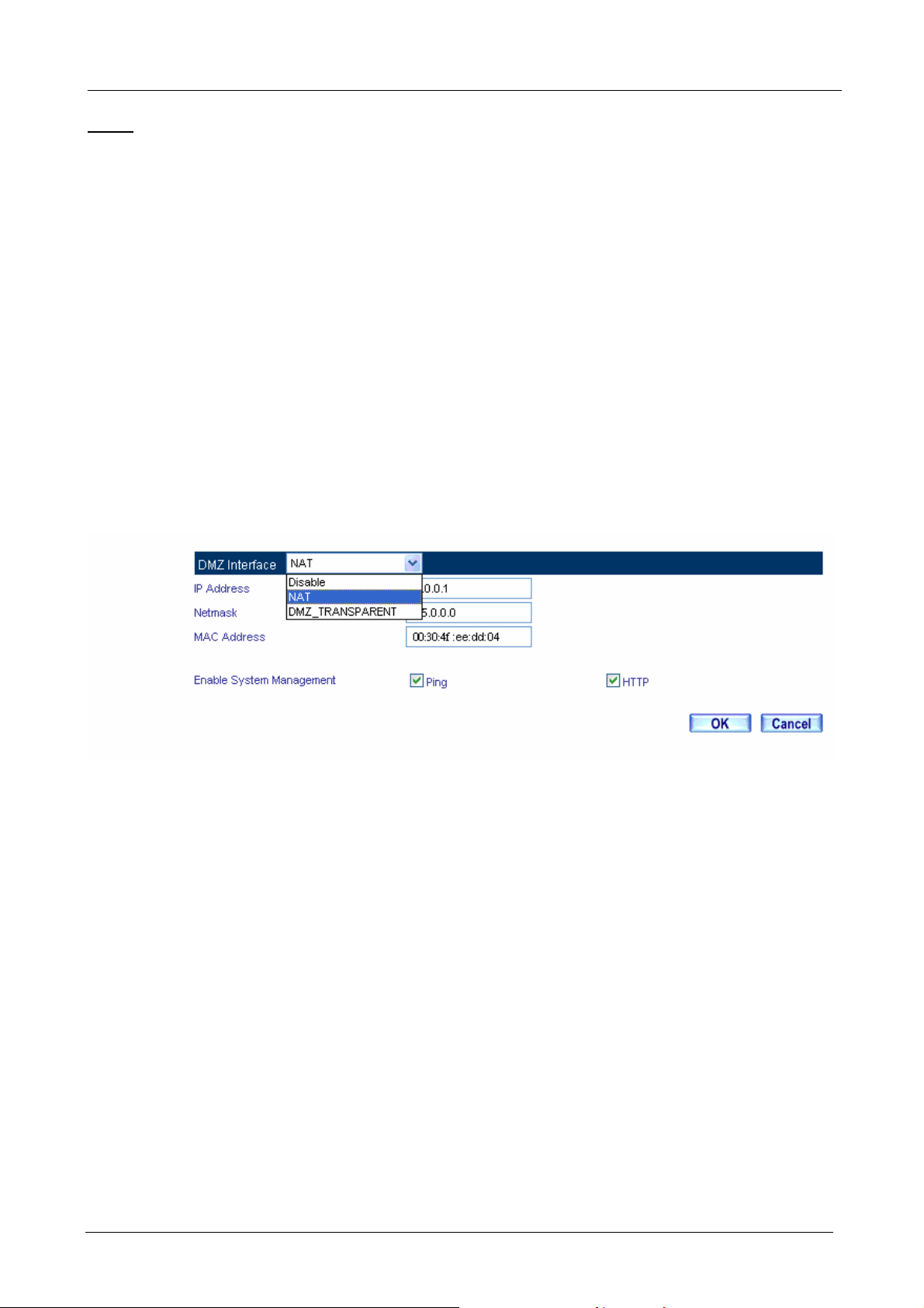
DMZ Interface: There are three options that you can select, Disable, NAT and Transparent.
IP Address: The private IP addre ss of MH-2001’s DMZ interface. This will be the IP address of the DMZ port.
If it is in NAT mode, the IP address cannot use the same network with the WAN or LAN network.
Netmask: This will be the subnet mask of the DMZ network.
Ping: Select this to allow the DMZ network to ping the IP Address of MH-2001. If set to enable, the device will
respond to echo request packets from the DMZ network.
HTTP: Select this to allow the device WEBUI to be accessed from the DMZ network. Keep in mind that the
device always requires a username and password to enter the WebUI.
Setting DMZ Interface Address (NAT Mode)
STEP 1﹒Click DMZ Interface
STEP 2﹒Select NAT Mode in DMZ Interface
Select NAT in DMZ Inter face
Enter IP Address and Netmask
STEP 3﹒Select Ping and HTTP
STEP 4﹒Click OK
Setting DMZ Interface Address (NAT Mode) WebUI
- 40 -
Page 47

MH-2001 Multi-Homing Security Gateway User’s Manual
Setting DMZ Interface Address (Transparent Mode)
STEP 1﹒Select DMZ Interface
STEP 2﹒Select Transparent Mode in DMZ Interface
Select DMZ_Transparent in DMZ Interface
STEP 3﹒Select Ping and HTTP
STEP 4﹒Click OK
Setting DMZ Interface Address (Transparent Mode) WebUI
In WAN, the connecting way must be Static IP Address and can choose Transparent Mode in DMZ.
- 41 -
Page 48

MH-2001 Multi-Homing Security Gateway User’s Manual
Chapter 6: Policy Object
6.1 Address
MH-2001 allows the Administrator to set addresses of the LAN network, LAN network group, WAN network,
WAN group, DMZ network and DMZ group. These settings are to be used for policy editing.
What is the Address Table?
An IP address in the Addre ss Table can be an addre ss of a computer or a sub ne twork. The Administrator can
assign an easily recognized name to an IP address. Based on the network it belongs to, an IP address can be
LAN IP address, WAN IP address and DMZ IP address. If the Administrator needs to create a control policy
for packets of different IP addresses, he can first add a new group in the LAN Network Group or the WAN
Network Group and assign those IP addresses into the newly created group. Using group addresses can
greatly simplify the process of building control policies.
How to use Address Table
With easily recognized names of IP addresses and names of address groups shown in the address table, the
Administrator can use these names as the source address or destination address of control policies. The
address table should be built before creating control policies, so that the Administrator can pick the names of
correct IP addresses from the address table when setting up control polici es.
6.1.1 LAN
Entering the LAN window
Step 1. Click LAN under the Address menu to enter the LAN window. The current setting information
such as the name of the LAN network, IP and Netmask addresses will show on the screen.
Definition
Name: Name of LAN network address.
IP: IP address of LAN network
Netmask: subnet mask of LAN network.
MAC Address: MAC address corresponded with LAN IP address.
Configure: You can configure the settings in LAN network. Click Modify to change the parameters in LAN
- 42 -
Page 49

MH-2001 Multi-Homing Security Gateway User’s Manual
network. Click Remove to delete the settings.
If one of the members has been added to Policy or LAN Group, the Configure column will show the
message –
. In this case, you are not allowed to modify or remove the setting.
Adding a new LAN Address
Step 1. In the LAN window, click the New Entry button.
Step 2. In the Add New Address window, enter the settings of a new LAN network address.
Step 3. If you want to enable Get Static IP address from DHCP Server function, enter the MAC
Address then check the Get Static IP address from DHCP Server.
Step 4. Click OK to add the specifi ed LAN network or click Cancel to cancel the changes.
When the System Administrator setting the Address Book, he/she can choose the way of clicking on
to make the MH-2001 to fill out the user’s MAC Address automatically.
In LAN of Address function, the MH-2001 has an default Inside Any address setting represents the
whole LAN network automatically. Others like WAN, DMZ also have the Out side Any and DMZ Any default
address setting to represent the whole subnet.
- 43 -
Page 50

MH-2001 Multi-Homing Security Gateway User’s Manual
6.1.2 LAN Group
Entering the LAN Group window
The LAN Addresses may be combined together to become a group.
Step 1. Click LAN Group under the Address menu to enter the LAN Group window. The curre nt setting
information for the LAN network group appears on the screen.
Definitions (LAN group):
Name: Name of the LAN group.
Member: Members of the group.
Configure: Configure the settings of LAN group. Click Modify to change the settings of LAN group. Click
Remove to delete the group.
If one of the LAN Group has been added to Policy, the Configure column will show the message –
. In this case, you are not allowed to modify or remove the LAN group. You have to delete the Group
in Policy window, and then you are allo wed to configure the LAN Group.
Adding a LAN Group
Step 1. In the LAN Group window, click the New Entry button to enter the Add New Address Group
window.
Step 2. In the Add New Address Group window:
Name: enter the name of the new group in the open field.
Av ailable Address: list the names of all the members of the LAN network.
Selected Address: list the names to be assigned to the new group.
Step 3. Add members: Select names to be added in Available Address list, and click the Add>> button
to add them to the Selected Address list.
Step 4. Remove members: Select names to be removed in the Selected Address list, and click the
<<Remove button to remove these members from Selected Address list.
Step 5. Click OK to add the new group or click Cancel to discard changes.
- 44 -
Page 51

MH-2001 Multi-Homing Security Gateway User’s Manual
6.1.3 WAN
Entering the WAN window
Step 1. Click WAN under the Address menu to enter the WAN window. The current setting information,
such as the name of the WAN network, IP and Netmask addresses will show on the screen.
Definitions
Name: Name of WAN network address.
IP/Netmask: IP address/Netmask of WAN network.
Configure: Configure the settings of WAN network. Click Modify to change the settings of WAN network.
Click Remove to delete the setting of WAN network.
NOTE: In the WA N Network window, if one of the members has been added to Policy or LAN Group, the
Configure column will show the message – In Use. In this case you are not allowed to modify or remove the
settings.
If one of the members has been added to Policy or WAN Group, the Configure column will show the
- 45 -
Page 52

MH-2001 Multi-Homing Security Gateway User’s Manual
message – . In this case, you are not allowed to modify or remove the setting. You have to remove
the setting in Policy or WAN Group, and then you are allowed to configure the WAN address.
Adding a new WAN Address
Step 1. In the WAN window, click the New Entry button.
Step 2. In the Add New Address window, enter the settings for a new WAN network address.
Step 3. Click OK to add the specifi ed WAN network or click Cancel to discard changes.
6.1.4 WAN Group
Entering the WAN Group window
Step 1. Click the WAN Group under the Address menu bar to enter the WAN window. The current
settings for the WAN network group(s) will appear on the screen.
Definitions:
Name: Name of the WAN group.
Member: Members of the group.
Configure: Configure the settings of WAN group. Click Modify to change the parameters of WAN group Click
Remove to delete the selected group.
If one of the WAN Group has been added to Policy, the Configure column will show the message –
. In this case, you are not allowed to modify or remove the WAN group. You have to remove the
Group in Policy window, and then you are allowed to configure the WAN Group.
- 46 -
Page 53

MH-2001 Multi-Homing Security Gateway User’s Manual
Adding an WAN Group
Step 2. In the WAN Group window, click the New Entry button and the Add New Address Group
window will appear.
Step 3. In the Add New Address Group window the following fields will appear:
Name: Enter the name of the new group.
Available Address: List the names of all the members of the WAN network.
Selected Address: List the names to assign to the new group.
Add members: Select the names to be added in the Available Address list, and click the
Add>> button to add them to the Selected Address list.
Remove members: Select the names to be removed in the Selected Address list, and click
the <<Remove button to remove them from the Selected Address list.
Step 4. Click OK to add the new group or click Cancel to discard changes.
6.1.5 DMZ
Entering the DMZ window:
Click DMZ under the Address menu to enter the DMZ window. The current setting information such as the
name of the DMZ network, IP, and Netmask addresses will show on the screen.
- 47 -
Page 54

MH-2001 Multi-Homing Security Gateway User’s Manual
Definition
Name: Name of DMZ network address.
IP: IP address of DMZ network
Netmask: subnet mask of DMZ network.
MAC Address: MAC address corresponded with DMZ IP addre ss.
Configure: You can configure the settings in DMZ network. Click Modify to change the parameters in DMZ
network. Click Remove to delete the settings.
If one of the members has been added to Policy or DMZ Group, the Configure column will show the
message –
the setting in Policy or DMZ Group, and then you are allowed to configure the DMZ address.
. In this case, you are not allowed to modify or remove the setting. You have to remove
Adding a new DMZ Address:
Step 1. In the DMZ window, click the New Entry button.
Step 2. In the Add New Address window, enter the settings for a new DMZ address.
Step 3. Click OK to add the specified DMZ or click Cancel to discard changes.
- 48 -
Page 55

MH-2001 Multi-Homing Security Gateway User’s Manual
6.1.6 DMZ Group
Entering the DMZ Group window
Click DMZ Group under the Address menu to enter the DMZ window. The current settings information for the
DMZ group appears on the screen.
Definitions:
Name: Name of the DMZ group.
Member: Members of the group.
Configure: Configure the settings of DMZ group. Click Modify to change the parameters of DMZ group Click
Remove to delete the selected group.
If one of the DMZ Group has been added to Policy, the Configure column will show the message –
. In this case, you are not allowed to modify or remove the DMZ group. You have to remove the
Group in Policy window, and then you are allowed to configure the DMZ Group.
Adding a DMZ Group:
Step 1. In the DMZ Group window, click the New Entry button and the Add New Address Group
window will appear.
Step 2. In the Add New Address Group window the following fields will appear:
Name: Enter the name of the new group.
Available Address: List the names of all the members of the DMZ network.
Selected Address: List the names to assign to the new group.
Add members: Select the names to be added in the Available Address list, and click the
Add>> button to add them to the Selected Address list.
Remove members: Select the names to be removed in the Selected Address list, and click
the <<Remove button to remove them from the Selected Address list.
Step 3. Click OK to add the new group or click Cancel to discard changes.
- 49 -
Page 56

MH-2001 Multi-Homing Security Gateway User’s Manual
- 50 -
Page 57

MH-2001 Multi-Homing Security Gateway User’s Manual
6.1.7 Example1
Under DHCP situation, assign the specific IP to static users and restrict them to
access FTP net service only through policy
STEP 1﹒Select LAN in Address and enter the following settings:
Click New Entry button
Name: Enter Rayearth
IP Address: Enter 192.168.3.2
Netmask: Enter 255.255.255.255
MAC Address : Enter the user’s MAC Address(00:B0:18:25:F5:89)
Select Get static IP address from DHCP Server
Click OK
Setting LAN Address Book WebUI
Complete the Setting of LAN
- 51 -
Page 58

MH-2001 Multi-Homing Security Gateway User’s Manual
STEP 2﹒Adding the following setting in Outgoing Policy:
Add a Policy of Restricting the Specific IP to Access to Internet
STEP 3﹒Complete assigning the specific IP to static users in Outgoing Policy and restrict them to access
FTP net service only through policy:
Complete the Policy of Restricting the Specific IP to Access to Internet
- 52 -
Page 59

MH-2001 Multi-Homing Security Gateway User’s Manual
6.1.8 Example2
Setup a policy that only allows partial users to connect with specific IP (External
Specific IP)
STEP 1 . Setting several LAN network Address.
Setting Several LAN Network Addres s
STEP 2 . Enter the following settings in LAN Group of Address:
Click New Entry
Enter the Name of the group
Select the users in the Available Address column and click Add
Click OK
Add New LAN Address Group
- 53 -
Page 60

MH-2001 Multi-Homing Security Gateway User’s Manual
Complete Adding LAN Address Group
The setting mode of WAN Group and DMZ Group of Address are the same as LAN Group.
STEP 3 . Enter the following settings in WAN of Address function:
Click New Entry
Enter the following data (Name, IP Address, Netmask)
Click OK
Add New WAN Address
Complete the Setting of WAN Address
- 54 -
Page 61

STEP 4 . To exercise STEP1~3 in Policy
MH-2001 Multi-Homing Security Gateway User’s Manual
To Exercise Address Setting in Policy
Complete the Policy Setting
The Address function really take effect only if use with Policy.
- 55 -
Page 62

MH-2001 Multi-Homing Security Gateway User’s Manual
6.2 Service
In this section, network services are defined and new network services can be added. There are three sub
menus under Service which are: Pre-defined, Custom, and Group. The Administrator can simply follow the
instructions below to define the protocols and port numbers for network communication applications. Users
then can connect to servers and other computers through these available network services.
What is Service?
TCP and UDP protocols support varieties of se rvices, and each service consists of a TCP Port or UDP port
number, such as TELNET(23), SMTP(21), POP3(110),etc. MH-2001 defines two services: pre-defined service
and custom service. The common-use services like TCP and UDP are defined in the pre-defined service and
cannot be modified or removed. In the custom menu, users can define othe r TCP port and UDP port numbers
that are not in the pre-defined menu according to their needs. When defining custom services, the client port
ranges from 0 to 65535 and the server port ranges from 0 to 65535.
How do I use Service?
The Administrator can add new service group names in the Group option under Service menu, and assign
desired services into that new group. Using service group the Administrator can simplify the processes of
setting up control policies. For example, there are 10 different computers that want to access 5 different
services on a server, such as HTTP, FTP, SMTP, POP3, and TELNET. Without the help of service groups, the
Administrator needs to set up 50 (10x5) control policies, but by applying all 5 services to a single group name
in the service field, it takes only one control policy to achieve the same effect as the 50 control policies.
6.2.1 Pre-defined
Entering a Pre-defined window
Step 1. Click Pre-defined unde r it. A window will appear with a list of services and their associated IP
addresses. This list cannot be modified.
- 56 -
Page 63

Icons and Descriptions
MH-2001 Multi-Homing Security Gateway User’s Manual
Figure
Description
Any Service
TCP services, e.g. TCP, FTP, FINGER, HTTP , HTTPS, IMAP, SMTP , POP3,
ANY, AOL, BGP, GOPHER, Inter Locator, IRC, L2TP, LDAP, NetMeeting,
NNTP, PPTP, Real Media, RLOGIN, SSH, TCP ANY, TELNET, VDO Live,
WAIS, WINFRAME, X-WINDOWS, MSN, etc.
UDP services, e.g. IKE, DNS, NTP, RIP, SNMP, SYSLOG, TALK, TFTP,
UDP-ANY, UUCP, NFS, PC Anywhere, etc.
ICMP services, e.g. PING, TRACEROUTE, etc.
6.2.2 Custom
Entering the Custom window
Step 1. Click Custom under Service menu. A window will appear with a table showing all services
currently defined by the Administrator.
Definitions:
Service name: The defined service name.
Protocol: Network protocol used in the basic setting. Such as TCP、UDP or oth ers.
Client port: The range of Client port in defined service. If the number of ports entered in the two fields of
Client port is different, it means that the port numbers between these two numbers are opened. If the number
of ports entered in the two fields of Client port is identical, it means that the entered port number is opened.
Server port: The range of Serer port in defined service.
If the number of ports entered in the two fields of Server port is different, it means that the port numbers
between these two numbers are opened. If the number of ports entered in the two fields of Server port is
identical, it means that the entered port number is opened.
Configure: Configure the settings in Service table. Click Modify to change the parameters in Service table.
Click Remove to delete the selected setting.
- 57 -
Page 64

MH-2001 Multi-Homing Security Gateway User’s Manual
If one of the Services has been added to Policy or Group, Configure column will show the message –
. In this case, you are not allowed to modify or remove t he settings. You have to remove the setting in
Policy or Group window, and then you are allowed to configure the settings.
Adding a new Service
Step 1. In the Custom window, click the New Entry button and a new se rvice table appears.
New Service Name: This will be the name referencing the new service.
Protocol: Enter the network protocol type to be used, such as TCP, UDP, or Other (please
enter the number for the protocol type).
Client Port: enter the range of port number of new clients.
Server Port: enter the range of port number of new servers.
Step 2. Click OK to add new se rvices, or click Cancel to cancel.
6.2.3 Group
Entering the Group window
Click Group under Service menu. A window will appear with a table displaying current servi c e group
settings.
- 58 -
Page 65

MH-2001 Multi-Homing Security Gateway User’s Manual
Definitions:
Group name: The Group name of the defined Service.
Service: The Service item of the Group.
Configure: Configure the settings of Group. Click Modify to change the parameters of the Group.
Click Remove to delete the Group.
If one of the Services has been added to Policy, Configure column will show the message – .
In this case, you are not allowed to modify or remove the settings. You have to remove the setting in Policy
window, and then you are allowed to configure the settings.
Adding Service Groups
Step 1. In the Group window, click the New Entry button.
Step 2. In the Add Service Group window, the following fields will appear:
Available Services: list all the available services.
Selected Services: list services to be assigned to the new group.
Step 3. Enter the new group name in the group Name field. This will be the name referencing the
created group.
Step 4. To add new services: Select the services desired to be added in the Available Services list
and then click the Add>> button to add them to the group.
Step 5. To remove services: Select services desired to be removed in the Selected Services, and
then click the <<Remove button to remove them from the group.
Step 6. Click OK to add the new group.
- 59 -
Page 66

MH-2001 Multi-Homing Security Gateway User’s Manual
6.3 Schedule
MH-2001 allows the Administrator to configure a schedule for policies to take affect. By creating a schedule,
the Administrator is allowing MH-2001 policies to be used at those designated times only. Any activities
outside of the scheduled time slot will not follow MH-2001 policies therefore will likely not be permitted to pass
through MH-2001. The Administrator can configure the start time and stop time, as well as creating 2 different
time periods in a day. For example, an organization may only want MH-2001 to allow the LAN network users
to access the Internet during work hours. Therefore, the Administrator may create a schedule to allow
MH-2001 to work Monday-Friday, 8AM - 5PM only. During the non-work hours, MH-2001 will not allow
Internet access.
Entering the Schedule window
Step 1. Click on Setting under Schedule menu and the schedule window will appea r displaying the active
schedules.
Definitions:
Name: The name assigned to the schedule
Configure: Configure the settings of Schedule. Click Modify to change the parameters of the Schedule.
Click Remove to delete the Schedule.
If one of the Schedule has been added to Policy, Configure column will show the message –
. In this case, you are not allowed to modify or remove t he settings. You have to remove the setting in
Policy window, and then you are all owed to configure the settings.
Adding a new Schedule
Step 1. Click on the New Entry button and the Add New Schedule window will appear.
Schedule Name: Fill in a name for the new schedule.
Period: Configure the start and stop time for the days of the week that the schedule will be
active.
Step 2. Click OK to save the new schedule or click Cancel to cancel adding the new schedule.
- 60 -
Page 67

MH-2001 Multi-Homing Security Gateway User’s Manual
In setting a Schedule, the value in Start time must be less than the value in Stop Time, or you cannot
add or configure the setting.
6.4 QoS
By configuring the QoS, you can control the outbound Upstream/downstream Bandwidth.
The administrator can configure the bandwidth according to the WAN bandwidth.
Downstream Bandwidth: T o configure the Guaranteed Bandwidth and Maximum Bandwidth.
Upstream Bandwidth: To configure the Guaranteed Bandwidth and Maximum Bandwidth.
QoS Priority: To configure the priority of distributing Upstream/Downstream and unused bandwidth.
MH-2001 configures the bandwidth by different QoS, and selects the suitable QoS through Policy to control
and efficiently distribute bandwidth. MH-2001 also makes it convenient for the administrator to make the
Bandwidth reach the best Utility.
The Flow Before Using QoS
- 61 -
Page 68

The Flow After Using Qo S (Max. Bandwidth: 400Kbps, Guaranteed Bandwidth: 200Kbps)
Configuration of QoS
MH-2001 Multi-Homing Security Gateway User’s Manual
Click on Setting under QoS menu and the QoS window will appear.
Definitions:
Name: The name of the QoS you want to configure.
WAN: Display WAN 1 or WAN 2.
Downstream Bandwidth: To configu re the Gua rante ed Bandwidth and Maximum Bandwidth.
Upstream Bandwidth: T o configure the Guaranteed Bandwidth and Maximum Bandwidth.
Priority: To configure the priority of distributing Upstream/Downstream and unused bandwidth.
Add New QoS
Step 1. Click on the New Entry button and the Add New QoS window will appear.
Name: The name of the QoS you want to define.
Downstream Bandwidth: To configure the Guaranteed Bandwidth and Maximum Bandwidth.
Upstream Bandwidth: To configure the Guaranteed Bandwidth and Maximum Bandwidt h.
QoS Priority: T o configure the priority of distributing Upstream/Downstream and unused
bandwidth.
- 62 -
Page 69

Step 2. Click the OK button to add new QoS.
MH-2001 Multi-Homing Security Gateway User’s Manual
6.5 Authentication
By configuring the Authentication, you can control the user’s connection authority. The user has to pass the
authentication to access to Internet.
The MH-2001 appliance provided 3 authentication modes. The User and User Group built in; others are
RADIUS and POP3 self-built Authentication Server. The MIS engineer can use the 4 modes, to manage the
authentication.
6.5.1 Auth Setting
The administrator can specify the port number and authentication time of authentication management system
for LAN user to access WAN network.
Configuration of Authentication
Click Authentication in the menu bar on the left hand side and click Auth Setting. The Authentication
Management window will appear as below.
- 63 -
Page 70

MH-2001 Multi-Homing Security Gateway User’s Manual
Definitions:
Authentication Port: The internal users have to pass the authentication to access to the Internet
when enable MH-2001.
Re-Login if Idle: When the internal user access to Internet, can setup the idle time after passing
authentication. If idle time exceeds the time you setup, the authentication will be invalid. The default
value is 30 minutes.
Re-Login after user login successfully:When the LAN user connect to the WAN through the
authentication. The available authentication time depends on the time limit, if over the default time
setting, the authentication will be invalid.
Disallow Re-Login if the auth user has login:When enable this function through User, User
Group, RADIUS or POP3 to access the authentication, the authorized account can not be used by
other people.
URL to redirect when authentication succeed: The user who had passes Authentication have to
connect to the specific website. (It will connect to the website directly which the user want to login)
The default value is blank.
Messages to display when user login: It will display the login message in the authentication
WebUI. (Support HTML) The default value is blank (display no message in authentication WebUI).
6.5.2 Auth User
Click Authentication in the menu bar on the left hand side and click Auth User.
Definitions:
Name:The name of the Authentication you want to configure.
Configure: modify settings or remove users.
Adding a new Auth User
Step 1. In the Authentication window, click the New User button to create a new Auth User.
Step 2. In the Auth-User window:
- 64 -
Page 71

MH-2001 Multi-Homing Security Gateway User’s Manual
Auth-User Name: enter the username of new Authentication.
Password: enter a password for the new Authentication.
Confirm Password: enter the password again.
Step 3. Click OK to add the user or click Cancel to cancel the setting
Step 4. In the form of controlling the [Outgoing] Policy, enable the Authentication-User Function.
- 65 -
Page 72

MH-2001 Multi-Homing Security Gateway User’s Manual
Step 5. When the user connect to external network by Authentication, the following page will be displayed.
Enter the User Name and Password for authentication.
Step 6. Authentication success, it will pop-up a window that you can logout and you can access to internet.
- 66 -
Page 73

MH-2001 Multi-Homing Security Gateway User’s Manual
6.5.3 Auth User Group
Entering the Auth User Group windo w
Click Authentication in the menu bar on the left hand side of the window and click Auth Group under it. A
window will appear with a table displaying current Auth User Group settings by the Administrator.
Adding Auth Group
STEP 1 . Add Auth Group Setting in Authentication function and enter the following settings:
Click New Entry
Name: Enter laboratory
Select the Auth User you want and Add to Selected Auth User
Click OK
Complete the setting of Auth User Group
Setting Auth Group WebUI
- 67 -
Page 74

MH-2001 Multi-Homing Security Gateway User’s Manual
STEP 2 . Add a policy in Outgoing Policy and input the Address and Authentication of STEP 1
Auth-User Policy Setting
Complete the Policy Setting of Auth-User
- 68 -
Page 75

MH-2001 Multi-Homing Security Gateway User’s Manual
STEP 3 . When user is going to access to Internet through browser, the authentication UI will appear in
Browser. After entering the correct user name and password, click OK to access to Internet.
Access to Internet through Authentication WebUI
STEP 4 . If the user does not need to access to Internet anymore and is going to logout, he/she can click
LOGOUT Auth-User to logout the system. Or enter the Logout Authentication WebUI (http:// LAN
Interface: Authentication port number/ logout.html) to logout.
Logout Auth-User WebUI
- 69 -
Page 76

MH-2001 Multi-Homing Security Gateway User’s Manual
6.5.4 Radius Server
To plan the users connect to the WAN through the authenticaton in policy .To use the
WAN RADIUS server (Windows 2003 Server built-in authentication).
※ Windows 2003 RADIUS Server Deployment
STEP 1 . Click Start Æ Control Panel Æ Add / Remove Programs select Add / Remove Windows
Components, and then it shows the Windows Components Wi zard.
STEP 2 . Select Networking Services, and then click Details.
Windows components wizard
- 70 -
Page 77

STEP 3 . Select Internet Authentication Service.
MH-2001 Multi-Homing Security Gateway User’s Manual
Add new network authentication service components
- 71 -
Page 78

MH-2001 Multi-Homing Security Gateway User’s Manual
STEP 4 . Click Start Æ Control Panel Æ Administrative Tools, select Network Authentication Service.
Select network authentication service
- 72 -
Page 79

MH-2001 Multi-Homing Security Gateway User’s Manual
STEP 5 . Right click RADIUS Clients Æ New RA DIUS Client.
Add new RADIUS client
- 73 -
Page 80

MH-2001 Multi-Homing Security Gateway User’s Manual
STEP 6 . Enter the Name and Client Address (It is the same as MH-2001 IP Address).
Add New RADIUS client name and IP address setting
- 74 -
Page 81

MH-2001 Multi-Homing Security Gateway User’s Manual
STEP 7 . Select RADISU Standard; enter the Shared secret and Confirm Shared secret. (It must be the
same setting as RADIUS in MH-2001.
Add new RADIUS client-vendor and shared secret
- 75 -
Page 82

MH-2001 Multi-Homing Security Gateway User’s Manual
STEP 8 . Right click on Remote Access PoliciesÆ New Remote Access Policy.
Add new romote access policies
- 76 -
Page 83

MH-2001 Multi-Homing Security Gateway User’s Manual
STEP 9 . Select Use the wizard to set up a typical policy for a common scenario, and enter the Policy
name.
Add new romote access policies and policy name
- 77 -
Page 84

STEP 10 . Select Ethernet.
MH-2001 Multi-Homing Security Gateway User’s Manual
The way to add new remote access policy
- 78 -
Page 85

STEP 11 . Select User.
MH-2001 Multi-Homing Security Gateway User’s Manual
Add new remote access policy user and group
- 79 -
Page 86

STEP 12 . Select MD5-Challenge.
MH-2001 Multi-Homing Security Gateway User’s Manual
The authentication of add new remote access policy
- 80 -
Page 87

MH-2001 Multi-Homing Security Gateway User’s Manual
STEP 13 . Right click on the Radius Æ Properties.
The network authentication service setting
- 81 -
Page 88

MH-2001 Multi-Homing Security Gateway User’s Manual
STEP 14 . Select Grant remote access permission, and Remove the original setting, then click Add.
The RADIUS properties settings
- 82 -
Page 89

STEP 15 . Add Service-Type.
MH-2001 Multi-Homing Security Gateway User’s Manual
Add new RADIUS properties attribute
- 83 -
Page 90

MH-2001 Multi-Homing Security Gateway User’s Manual
STEP 16 . Add Authenticate Only from the left side.
Add RADIUS properties service-type
- 84 -
Page 91

MH-2001 Multi-Homing Security Gateway User’s Manual
STEP 17 . Click Edit Profile, select Authentication, and check Unencrypted authentication (PAP, SPAP).
Edit RADIUS service-type dial-in property
- 85 -
Page 92

MH-2001 Multi-Homing Security Gateway User’s Manual
STEP 18 . Add Auth User, click Start Æ Setting Æ Control PanelÆAdministrative Tools, select
Computer Management.
Enter computer management
- 86 -
Page 93

STEP 19 . Right click on Users, select New User.
MH-2001 Multi-Homing Security Gateway User’s Manual
Add new user
STEP 20 . Complete the Windows 2003 RADIUS Server Settings.
- 87 -
Page 94

MH-2001 Multi-Homing Security Gateway User’s Manual
STEP 21 . In Authentication Æ RADIUS function, enter IP, Port and Shared Secret. (The setting must be
the same as RADIUS server).
The RADIUS server setting
STEP 22 . In Authentication Æ User Group, add new Radius User.
Add new RADIUS user
Complete adding a RADIUS Authentication
- 88 -
Page 95

MH-2001 Multi-Homing Security Gateway User’s Manual
STEP 23 . In Policy Æ Outgoing, apply the Authentication Group (RADIUS included) in STEP22. To add
the new policy.
To add the RADIUS authentication policy
Complete the RADIUS authentication policy setting
STEP 24 . When the users connect to the network via the browser, it will show the authentication window.
Enter the user name and password, click OK, and then link to the network through the MH-2001.
Link to the network through the authentication window
- 89 -
Page 96

MH-2001 Multi-Homing Security Gateway User’s Manual
6.5.5 POP3
To plan the users connect to the WAN through the authentication by policy. (To use
the WAN POP3 server authentication)
STEP 1 . In Authentication Æ POP3, add the new setting as following.
The POP3 server setting
STEP 2 . In Authentication Æ User Group, add new POP3 User.
Add new POP3 user
Complete adding a new POP3 Authentication
- 90 -
Page 97

MH-2001 Multi-Homing Security Gateway User’s Manual
STEP 3 . In Policy Æ Outgoing, apply the Step2 (The authentication grou p) in to the policy.
The POP3 server authentication in policy setting
Complete the POP3 server authentication in policy setting
STEP 4 . When the users want to connect to the network via browser, it will show the authentication window.
Enter the user name and password, click OK then link to the network through the MH-2001 applia nce.
Link to the network through the authentication window
- 91 -
Page 98

MH-2001 Multi-Homing Security Gateway User’s Manual
6.6 Content Blocking
Content Filtering includes “URL Blocking”, “Script Blocking”, “Download Blocking” and “Upload
Blocking”.
URL Blocking: The administrator can use a complete domain name or key word to make rules for specific
websites.
Script Blocking: To let Popup、ActiveX、Java、Cookie in or keep them out.
Download Blocking: Block download connection, audio and video transferring from web page. You can
select to block which type of extension name or all type of the file.
Upload Blocking: Block upload connection, audio and video transferring to Internet. You can select to block
which type of extension name or all type of the file.
6.6.1 URL Blocking
The Administrator may setup URL Blocking to prevent LAN network users from accessing a specific website
on the Internet. Any web request coming from an LAN network computer to a blocked website will receive a
blocked message instead of the website.
Entering the URL blocking window
Step 1. Click on URL under the Content Blocking menu bar and the screen will display as below..
Definition:
URL String: The domain name that is blocked to enter by MH-2001.
Configure: To change the settings of URL Blocking, click Modify to change the parameters; click Remove to
delete the settings.
Adding a URL Blocking policy
Step 1. After clicking New Entry, the Add New Block String window will appear.
Step 2. Enter the URL String of the website to be blocked.
- 92 -
Page 99

MH-2001 Multi-Homing Security Gateway User’s Manual
Step 3. Click OK to add the policy. Click Cancel to discard changes.
Step 4. After finishing Content Filtering setting, you must enable it at Outgoing Policy, or Content
Filtering will not be workable.
You can use the symbol to help you configure the URL Blocking.
Symbol:
Restrict not to enter specific website:
~ means open up; * means metacharacter
Enter the 「complete domain name」 or 「key word」of
the website you want to restrict in URL String. For example: www.kcg.gov .tw or gov.
Only open specific website to enter:
1. Add the website you want to open up in URL String. While adding, you must enter the
symbol “~” in front of the 「compl ete domain name」or「key word」that represent s to open
these website to enter. For Example: ~www.kcg.gov.tw or ~gov.
2. After setting up the website you want to open up, enter an order to “forbid all” in the last
URL String; means only enter * in URL String.
Warning! The order to forbid all must be placed at last forever. If you want to open a new website, you
must delete the order of forbidding all and then enter the new domain name. At last, re-enter the “forbid all”
order again.
- 93 -
Page 100

MH-2001 Multi-Homing Security Gateway User’s Manual
6.6.2 Script Blocking
To let Popup, ActiveX, Java, or Cookies in or keep them out.
Step 1. Click Content Blocking in the menu.
Step 2. Script Blocking detective functions.
Popup: Prevent pop-up boxes from appearing.
ActiveX: Prevent ActiveX packets.
Java: Prevent Java packets.
Cookie: Prevent Cookie packets.
Step 3. After selecting each function, click the OK button below.
Step 4. After finishing Script Blocking setting, you must enable it at Outgoing Policy, or Content Filtering
will not be workable.
The users may not use the specific function (like JAVA, cookie…etc.) to browse the website through thi s
policy. It can forbid the user browsing stock exchange website…etc.
- 94 -
 Loading...