

Page 1

Page 2

User’s Manual of MGSD-10080F
Trademarks
Copyright © PLANET Technology Corp. 2021.
Contents are subject to revision without prior notice.
PLANET is a registered trademark of PLANET Technology Corp. All other trademarks belong to their respective owners.
Disclaimer
PLANET Technology does not warrant that the hardware will work properly in all environments and applications, and makes no
warranty and representation, either implied or expressed, with respect to the quality, performance, merchantability, or fitness for
a particular purpose. PLANET has made every effort to ensure that this User's Manual is accurate; PLANET disclaims liability
for any inaccuracies or omissions that may have occurred.
Information in this User's Manual is subject to change without notice and does not represent a commitment o n the part of
PLANET. PLANET assumes no responsib ili ty f or a ny in ac curacies that may be contained in this User's Manual. PLANET makes
no commitment to updat e or k eep cur re nt the information in this User's Manual, and re serves the right to ma ke i mpr ov em ent s to
this User's Manual and/or to the products described in this User's Manual, at any time without notice.
If you find information in this manual that is incorrect, misleading, or incomplete, we would appreciate your comments and
suggestions.
FCC Warning
This equipment has been tested and found to comply with the limits for a Class A digital device, pursuant to Part 15 of the FCC
Rules. These limits ar e de sign ed to prov ide r e as onab le protection against harmful in terf er e nce when the equipment is operated
in a commercial environment. This equipment generates, uses, and can radiate radio frequency energy and, if not installed and
used in accordance with the Instruction manual, may cause harmful interference to radio communications. Operation of this
equipment in a residential area is likely to cause harmful interference in which case the user will be required to correct the
interference at his own expense.
CE Mark Warning
This device is compliant with Class A of CISPR 32. In a residential environment this equipment may cause radio interfer ence .
Energy Saving Note of the Device
This power required device does not support Standby mode operation. For energy savings, please remove the power cable to
disconnect the device from the power circuit. Without removing the power cable, the device will still consume powe r from the
power source. In view of Saving the Energy and reducing the unnecessary power consumption, it is s trongly suggested to
remove the power cable from the device if this device is not intended to be active.
WEEE Warning
To avoid the potential effects on the environment and human health as a result of the presence of
hazardous substances in electrical and electronic equipment, end users of electrical and electronic
equipment should understand the meaning of the crossed-out wheeled bin symbol. Do not dispose of
WEEE as unsorted municipal w aste and have to colle ct such WEEE separately.
Revision
User's Manual of PLANET L2+ Metro Ethernet Switch
FOR MODEL: MGSD-10080F
REVISION:2.0 (November, 2021)
Part No: EM- MGSD-10080F_v2.0
2
Page 3

User’s Manual of MGSD-10080F
TABLE OF CONTENTS
1. INTRODUCTION ................................................................................................................. 10
1.1 Packet Contents ................................................................................................................................................ 10
1.2 Product Description ......................................................................................................................................... 11
1.3 How to Use This Manual .................................................................................................................................. 16
1.4 Product Features .............................................................................................................................................. 17
1.5 Product Specifications ................................................................................................................................. 20
2. INSTALLATION ................................................................................................................... 24
2.1 Hardware Description ....................................................................................................................................... 24
2.1.1 Switch Front Panel ..................................................................................................................................................... 24
2.1.2 Wiring the AC Power Input ........................................................................................................................................ 28
2.1.3 Wiring the DC Power Input ........................................................................................................................................ 29
2.1.4 Wiring the Fault Alarm Contact ................................................................................................................................. 30
2.1.5 Wiring the Digital Input/Output ................................................................................................................................. 30
2.2 Installing the Managed Metro Switch.............................................................................................................. 33
2.2.1 Desktop Installation ................................................................................................................................................... 33
2.2.2 Rack Mounting ........................................................................................................................................................... 34
2.3 Cabling ............................................................................................................................................................... 35
2.3.1 Installing the SFP Transceiver .................................................................................................................................. 36
2.3.2 Removing the SFP Transceiver ................................................................................................................................. 38
3. SWITCH MANAGEMENT .................................................................................................... 39
3.1 Requirements .................................................................................................................................................... 39
3.2 Management Access Overview ....................................................................................................................... 40
3.3 CLI Mode Management ..................................................................................................................................... 41
3.4 Web Management ............................................................................................................................................. 43
3.5 SNMP-based Network Management ............................................................................................................... 44
3.6 PLANET Smart Discovery Utility ..................................................................................................................... 44
4. WEB CONFIGURATION ...................................................................................................... 46
4.1 Main Web page .................................................................................................................................................. 49
4.2 System ............................................................................................................................................................... 51
4.2.1 Management ............................................................................................................................................................... 52
4.2.1.1 System Information .............................................................................................................................................. 52
4.2.1.2 IP Configuration ................................................................................................................................................... 53
4.2.1.3 IP Status .............................................................................................................................................................. 56
4.2.1.4 ARP Table ............................................................................................................................................................ 57
4.2.1.5 Users Configuration ............................................................................................................................................. 58
4.2.1.6 Privilege Levels ................................................................................................................................................... 61
3
Page 4

User’s Manual of MGSD-10080F
4.2.1.7 NTP Configuration ............................................................................................................................................... 63
4.2.1.7.1 System Time Correction Manually .................................................................................................................... 64
4.2.1.8 Time C onfi guration .............................................................................................................................................. 65
4.2.1.9 UPnP ................................................................................................................................................................... 67
4.2.1.10 DHCP Relay ...................................................................................................................................................... 69
4.2.1.11 DHCP Relay Statistics ....................................................................................................................................... 71
4.2.1.12 CPU Load .......................................................................................................................................................... 73
4.2.1.13 System Log ........................................................................................................................................................ 74
4.2.1.14 Detailed Log ...................................................................................................................................................... 75
4.2.1.15 Remote Syslog .................................................................................................................................................. 76
4.2.1.16 SMTP Configuration .......................................................................................................................................... 77
4.2.1.17 Fault Alarm ........................................................................................................................................................ 78
4.2.1.18 Digital Input/Output ............................................................................................................................................ 79
4.2.2 Simple Network Management Protocol .................................................................................................................... 82
4.2.2.1 SNMP Overview .................................................................................................................................................. 82
4.2.2.2 SNMP System Configuration ............................................................................................................................... 83
4.2.2.3 SNMP System Information .................................................................................................................................. 84
4.2.2.4 SNMP Trap Configuration .................................................................................................................................... 85
4.2.2.5 SNMP Trap Source Configuration........................................................................................................................ 87
4.2.2.6 SNMPv3 Communities......................................................................................................................................... 89
4.2.2.7 SNMPv3 Users .................................................................................................................................................... 90
4.2.2.8 SNMPv3 Groups .................................................................................................................................................. 92
4.2.2.9 SNMPv3 Views .................................................................................................................................................... 93
4.2.2.10 SNMPv3 Access ................................................................................................................................................ 94
4.2.3 RMON .......................................................................................................................................................................... 95
4.2.3.1 RMON Alarm Configuration ................................................................................................................................. 95
4.2.3.2 RMON Alarm Status............................................................................................................................................. 97
4.2.3.3 RMON Event Configuration ................................................................................................................................. 98
4.2.3.4 RMON Event Status............................................................................................................................................. 99
4.2.3.5 RMON History Configuration ............................................................................................................................. 100
4.2.3.6 RMON History Status ......................................................................................................................................... 101
4.2.3.7 RMON Statistics Configuration .......................................................................................................................... 102
4.2.3.8 RMON Statistics Status ...................................................................................................................................... 103
4.2.4 DHCP server ............................................................................................................................................................. 105
4.2.4.1 DHCP Server Mode Configuration ..................................................................................................................... 105
4.2.4.2 DHCP Server excluded IP Configuration ........................................................................................................... 107
4.2.4.3 DHCP Server pool Configuration ....................................................................................................................... 108
4.2.4.4 DHCP Server Statistics ...................................................................................................................................... 109
4.2.4.5 DHCP Server Binding IP Configuration ............................................................................................................. 111
4.2.4.6 DHCP Server Declined IP .................................................................................................................................. 112
4.2.4.7 DHCP Detail Statistics ....................................................................................................................................... 112
4
Page 5

User’s Manual of MGSD-10080F
4.2.5 Remote Management ............................................................................................................................................... 114
4.3 Switching ......................................................................................................................................................... 116
4.3.1 Port Management ..................................................................................................................................................... 116
4.3.1.1 Port Configuration .............................................................................................................................................. 116
4.3.1.2 Port Statistics Overview ..................................................................................................................................... 118
4.3.1.3 Port Statistics Detail ........................................................................................................................................... 119
4.3.1.4 SFP Module Information .................................................................................................................................... 121
4.3.1.5 Port Mirror .......................................................................................................................................................... 123
4.3.1.6 Name Map ......................................................................................................................................................... 126
4.3.2 Link Aggregation ...................................................................................................................................................... 127
4.3.2.1 Common Aggregation Configuration .................................................................................................................. 129
4.3.2.2 Static Aggregation Group Configuration ............................................................................................................. 130
4.3.2.3 Static Aggregation Status ................................................................................................................................... 131
4.3.2.4 LACP Configuration ........................................................................................................................................... 132
4.3.2.5 LACP System Status ......................................................................................................................................... 134
4.3.2.6 LACP Internal Status ......................................................................................................................................... 135
4.3.2.7 LACP Neighbor Port Status ............................................................................................................................... 136
4.3.2.8 LACP Port Statistics ........................................................................................................................................... 137
4.3.3 VLAN ......................................................................................................................................................................... 138
4.3.3.1 VLAN Overview ................................................................................................................................................. 138
4.3.3.2 IEEE 802.1Q VLAN ........................................................................................................................................... 139
4.3.3.3 VLAN Port Configuration ................................................................................................................................... 144
4.3.3.4 VLAN Membership Status .................................................................................................................................. 149
4.3.3.5 VLAN Port Status ............................................................................................................................................... 150
4.3.3.6 Private VLAN ..................................................................................................................................................... 152
4.3.3.7 Port Isolation ...................................................................................................................................................... 154
4.3.3.8 VLAN setting example: ...................................................................................................................................... 156
4.3.3.9 MAC-based VLAN ............................................................................................................................................. 162
4.3.3.10 IP Subnet-based VLAN Membership Configuration ......................................................................................... 163
4.3.3.11 Protocol-based VLAN ...................................................................................................................................... 164
4.3.3.12 Protocol-based VLAN Membership ................................................................................................................. 165
4.3.2.13 VLAN Translation ............................................................................................................................................. 167
4.3.4 Spanning Tree Protocol ........................................................................................................................................... 171
4.3.4.1 Theory ............................................................................................................................................................... 171
4.3.4.2 STP System Configuration ................................................................................................................................ 177
4.3.4.3 Bridge Status ..................................................................................................................................................... 180
4.3.4.4 CIST Port Configuration ..................................................................................................................................... 181
4.3.4.5 MSTI Priorities ................................................................................................................................................... 184
4.3.4.6 MSTI Configuration ............................................................................................................................................ 185
4.3.4.7 MSTI Ports Configuration .................................................................................................................................. 186
4.3.4.8 Port Status ......................................................................................................................................................... 188
5
Page 6

User’s Manual of MGSD-10080F
4.3.4.9 Port Statistics ..................................................................................................................................................... 189
4.3.5 Multicast .................................................................................................................................................................... 190
4.3.5.1 IGMP Snooping ................................................................................................................................................. 190
4.3.5.2 Profile Table ....................................................................................................................................................... 194
4.3.5.3 Address Entry .................................................................................................................................................... 195
4.3.5.4 IGMP Snooping Configuration ........................................................................................................................... 196
4.3.5.5 IGMP Snooping VLAN Configuration ................................................................................................................. 198
4.3.5.6 IGMP Snooping Port Group Filtering ................................................................................................................. 200
4.3.5.7 IGMP Snooping Status ...................................................................................................................................... 201
4.3.5.8 IGMP Groups Information .................................................................................................................................. 202
4.3.5.9 IGMPv3 Information ........................................................................................................................................... 203
4.3.6 MLD Snooping .......................................................................................................................................................... 204
4.3.6.1 MLD Snooping Configuration ............................................................................................................................. 204
4.3.6.2 MLD Snooping VLAN Configuration .................................................................................................................. 205
4.3.6.3 MLD Snooping Port Group Filtering ................................................................................................................... 207
4.3.6.4 MLD Snooping Status ........................................................................................................................................ 208
4.3.6.5 MLD Groups Information ................................................................................................................................... 209
4.3.6.6 MLDv2 Information ............................................................................................................................................ 210
4.3.7 MVR (Multicast VLAN Registration) ........................................................................................................................ 212
4.3.7.1 MVR Configuration ............................................................................................................................................ 213
4.3.7.2 MVR Status ........................................................................................................................................................ 215
4.3.7.3 MVR Groups Information ................................................................................................................................... 216
4.3.7.4 MVR SFM Information ....................................................................................................................................... 217
4.3.8 LLDP .......................................................................................................................................................................... 218
4.3.8.1 Link Layer Discovery Protocol ........................................................................................................................... 218
4.3.8.2 LLDP Configuration ........................................................................................................................................... 218
4.3.8.3 LLDP Neighbors ................................................................................................................................................ 221
4.3.8.4 LLDP-MED Configuration .................................................................................................................................. 222
4.3.8.5 LLDP-MED Neighbors ....................................................................................................................................... 229
4.3.8.6 Port Statistics ..................................................................................................................................................... 233
4.3.9 MAC Address Table .................................................................................................................................................. 235
4.3.9.1 MAC Tabl e Configuration ................................................................................................................................... 235
4.3.9.2 MAC Address Table Status ................................................................................................................................ 237
4.3.10 Loop Protection ...................................................................................................................................................... 239
4.3.10.1 Configuration ................................................................................................................................................... 239
4.3.10.2 Loop Protection Status..................................................................................................................................... 240
4.3.11 UDLD ....................................................................................................................................................................... 241
4.3.11.1 UDLD Port Configuration ................................................................................................................................. 241
4.3.11.2 UDLD Status .................................................................................................................................................... 242
4.3.12 GVRP ....................................................................................................................................................................... 244
4.3.12.1 GVRP Configuration ........................................................................................................................................ 245
6
Page 7

User’s Manual of MGSD-10080F
4.3.12.2 GVRP Port Configuration ................................................................................................................................. 246
4.3.13 PTP .......................................................................................................................................................................... 247
4.3.13.1 PTP Configuration ........................................................................................................................................... 248
4.3.14 Link OAM ................................................................................................................................................................ 256
4.3.14.1 Statistics .......................................................................................................................................................... 256
4.3.14.2 Port Status ....................................................................................................................................................... 258
4.3.14.3 Event Status .................................................................................................................................................... 260
4.3.14.4 Port Settings .................................................................................................................................................... 262
4.3.14.5 Event Settings ................................................................................................................................................. 264
4.3.14.6 MIB Retrieval ................................................................................................................................................... 265
4.3.14.7 Link-OAM Example .......................................................................................................................................... 266
4.4 Quality of Service ........................................................................................................................................... 267
4.4.1 General ...................................................................................................................................................................... 267
4.4.1.1 QoS Port Classification ...................................................................................................................................... 268
4.4.1.2 Queue Policing .................................................................................................................................................. 270
4.4.1.3 Port Tag Remarking ........................................................................................................................................... 271
4.4.1.4 Statistics ............................................................................................................................................................ 272
4.4.2 Bandwidth Control ....................................................................................................................................... 273
4.4.2.1 Port Policing ...................................................................................................................................................... 273
4.4.2.2 Port Schedule .................................................................................................................................................... 274
4.4.2.3 Port Shaping ...................................................................................................................................................... 276
4.4.3 Storm Control ........................................................................................................................................................... 278
4.4.3.1 Storm Policing Configuration ............................................................................................................................. 278
4.4.4 Differentiated Service .............................................................................................................................................. 279
4.4.4.1 Port DSCP ......................................................................................................................................................... 279
4.4.4.2 DSCP-based QoS ...................................................................................................................................... 281
4.4.4.3 DSCP Translation .............................................................................................................................................. 282
4.4.4.4 DSCP Classification ........................................................................................................................................... 283
4.4.5 QCL............................................................................................................................................................................ 284
4.4.5.1 QoS Control List ................................................................................................................................................ 284
4.4.5.2 QoS Control Entry Configuration ....................................................................................................................... 286
4.4.5.3 QCL Status ........................................................................................................................................................ 288
4.4.5.4 Voice VLAN Configuration ................................................................................................................................. 290
4.4.5.5 Voice VLAN OUI Table ....................................................................................................................................... 292
4.5 Security ............................................................................................................................................................ 293
4.5.1 Access Security ........................................................................................................................................................ 293
4.5.1.1 Access Management ......................................................................................................................................... 293
4.5.1.2 Access Management Statistics .......................................................................................................................... 294
4.5.1.3 SSH ................................................................................................................................................................... 295
4.5.1.4 HTTPs ............................................................................................................................................................... 296
4.5.2 AAA ........................................................................................................................................................................... 298
7
Page 8

User’s Manual of MGSD-10080F
4.5.2.1 Authenticatio n Configuration .............................................................................................................................. 303
4.5.2.2 RADIUS ............................................................................................................................................................. 305
4.5.2.3 TACACS+ .......................................................................................................................................................... 307
4.5.2.4 RADIUS Overview ............................................................................................................................................. 309
4.5.2.5 RADIUS Details ................................................................................................................................................. 310
4.5.3 Port Authentication .................................................................................................................................................. 317
4.5.3.1 Network Access Server Configuration ............................................................................................................... 317
4.5.3.2 Network Access Overview ................................................................................................................................. 321
4.5.3.3 Network Access Statistics .................................................................................................................................. 322
4.5.4 Port Security ............................................................................................................................................................. 327
4.5.4.1 Port Limit Control ............................................................................................................................................... 327
4.5.4.2 Port Security Status ........................................................................................................................................... 330
4.5.4.3 Port Security Detail ............................................................................................................................................ 332
4.5.5 Access Control Lists ................................................................................................................................................ 333
4.5.5.1 Access Control List Status ................................................................................................................................. 333
4.5.5.2 Access Control List Configuration ...................................................................................................................... 335
4.5.5.3 ACE Configuration ............................................................................................................................................. 337
4.5.5.4 ACL Ports Configuration .................................................................................................................................... 347
4.5.5.5 ACL Rate Limiters .............................................................................................................................................. 349
4.5.6 DHCP Snooping ........................................................................................................................................................ 350
4.5.6.1 DHCP Snooping Configuration .......................................................................................................................... 351
4.5.6.2 Snooping Table .................................................................................................................................................. 352
4.5.7 IP Source Guard ....................................................................................................................................................... 353
4.5.7.1 IP Source Guard Configuration .......................................................................................................................... 353
4.5.7.2 Static IP Source Guard Table ............................................................................................................................. 354
4.5.7.3 Dynamic IP Source Guard Table ........................................................................................................................ 355
4.5.8 ARP Inspection ......................................................................................................................................................... 356
4.5.8.1 ARP Inspection .................................................................................................................................................. 356
4.5.8.2 ARP Inspection Static Table ............................................................................................................................... 357
4.5.8.3 Dynamic ARP Inspection Table .......................................................................................................................... 358
4.6 Ring .................................................................................................................................................................. 360
4.6.1 ERPS Ring ................................................................................................................................................................ 360
4.6.1.1 MEP Configuration ............................................................................................................................................. 361
4.6.1.2 Detailed MEP Configuration .............................................................................................................................. 363
4.6.1.3 Ethernet Ring Protocol Switch ........................................................................................................................... 368
4.6.1.4 Ethernet Ring Protocol Switch Configuration ..................................................................................................... 370
4.6.1.5 Ethernet Ring Protocol Switch ........................................................................................................................... 373
4.6.1.6 Ring Wizard Example ........................................................................................................................................ 374
4.7 Maintenance .................................................................................................................................................... 377
4.7.1 Switch Maintenance ................................................................................................................................................. 377
4.7.1.1 Web Firmware Upgrade ..................................................................................................................................... 377
8
Page 9

User’s Manual of MGSD-10080F
4.7.1.2 Save Startup Config ........................................................................................................................................... 378
4.7.1.3 Configuration Download .................................................................................................................................... 378
4.7.1.4 Configuration Upload ......................................................................................................................................... 379
4.7.1.5 Configuration Activate ........................................................................................................................................ 380
4.7.1.6 Configuration Delete .......................................................................................................................................... 380
4.7.1.7 Image Select ...................................................................................................................................................... 381
4.7.1.8 Factory Default .................................................................................................................................................. 382
4.7.1.9 System Reboot .................................................................................................................................................. 382
4.7.2 Diagnostics ............................................................................................................................................................... 383
4.7.2.1 Ping ................................................................................................................................................................... 384
4.7.2.2 IPv6 Ping ........................................................................................................................................................... 386
4.7.2.3 Remote IP Ping.................................................................................................................................................. 387
4.7.2.4 Cable Diagnostics .............................................................................................................................................. 388
4.7.2.5 Tr acer outer (IP v 4) ............................................................................................................................................... 390
4.7.2.6 Tr acer outer (IP v 6) ............................................................................................................................................... 392
5. COMMAND LINE MODE ................................................................................................... 394
6. SWITCH OPERATION ....................................................................................................... 397
6.1 Address Table ................................................................................................................................................. 397
6.2 Learning ........................................................................................................................................................... 397
6.3 Forwarding & Filtering ................................................................................................................................... 397
6.4 Store-and-Forward .......................................................................................................................................... 397
6.5 Auto-Negotiation ............................................................................................................................................. 398
7. TROUBLESHOOTING ....................................................................................................... 399
APPENDIX A: Networking Connection ............................................................................... 400
A.1 Switch's Data RJ45 Pin Assignments - 1000Mbps, 1000BASE-T .............................................................. 400
A.2 10/100Mbps, 10/100BASE-TX ........................................................................................................................ 400
APPENDIX B : GLOSSARY .................................................................................................. 402
9
Page 10

User’s Manual of MGSD-10080F
1. INTRODUCTION
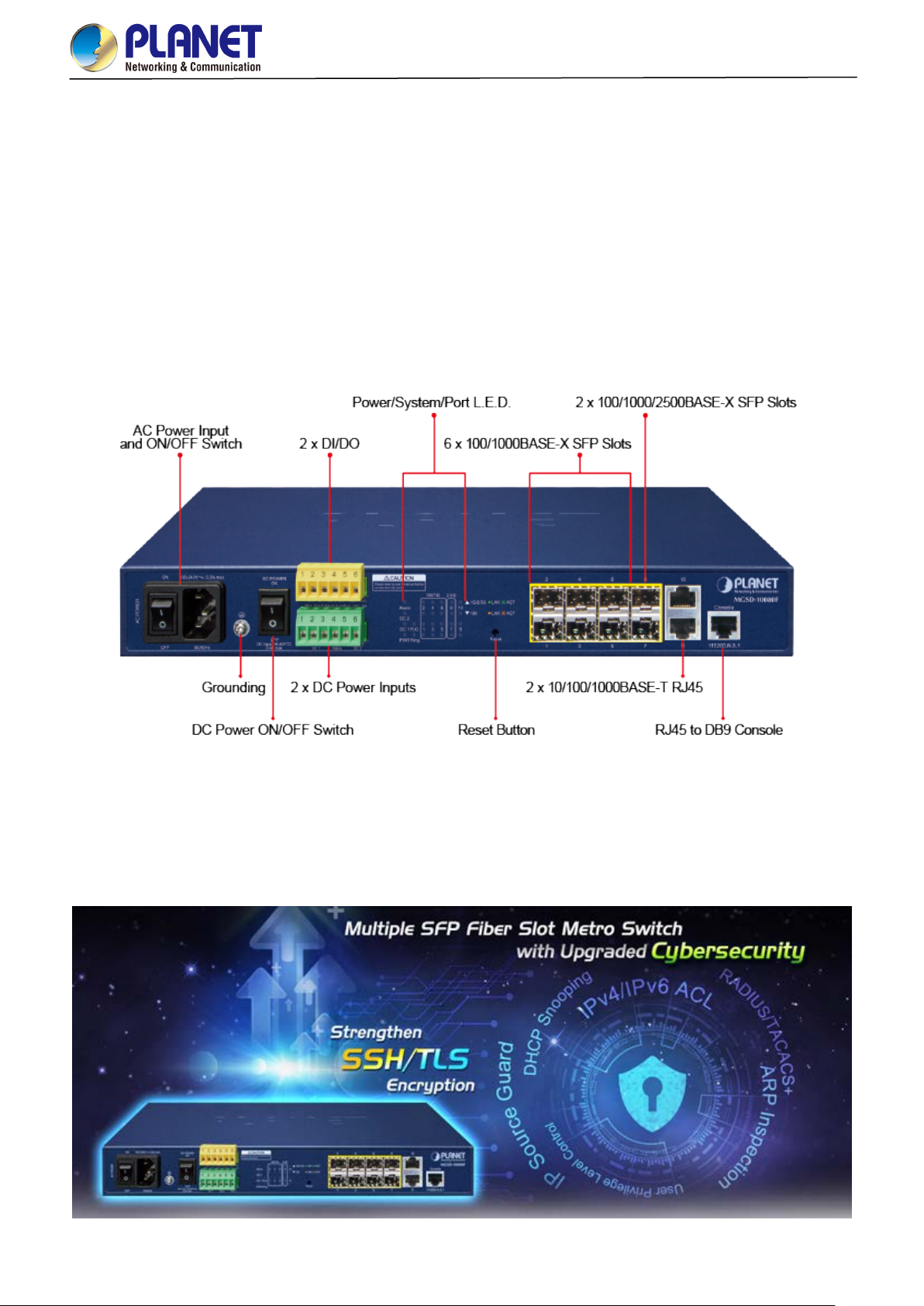
Thank you for purchasing PLANET L2+ Metro Ethernet Switch, th e MGSD-10080F. The de scriptions of this model are as
follows:
MGSD-10080F 6-Port 100/1000X SFP + 2-Port 1G/2.5G SFP + 2-Port 10/100/1000T Managed Metro Ethernet Switch
“Managed Metro Switch” is used as an alternative name for the above model in this user’s manual.
1.1 Packet Contents
Open the box of the Managed Metro Switch and carefully unpack it. The box should contain the following items:
Model Name
MGSD-10080F
Package Item
The Managed Metro Switch
Quick Installation Guide
RJ45 to RS232 Console Cable
Rubber Feet
■
■
■
■
Two Rack-mounting Brackets with
■
Attachment Screws
Power Cord
RJ45
■
3
Dust Caps
SFP
If any of these are missing or damaged, please contact your dealer immediately; if possible, retain the carton including the
original packing material, and use them again to repack the product in case there is a need to return it to us for repair.
8
10
Page 11
User’s Manual of MGSD-10080F
1.2 Product Description
Multiple SFP Fiber Port Switch for Growing Long-Reach Networking of Enterprises,
Telecoms and Campuses
PLANET MGSD-10080F Managed Metro Ethernet Switch is equipped with adv anc ed man a geme nt funct ions and provides 6
100/1000Mbps dual speed SFP Fiber ports, 2 100/1000/2500Mbps SFP ports and 2 10/100/1000Mbps TP ports delivered in
a rugged strong case. It is capable of providing non-blocking switch fabric and wire-speed through put as hig h as 26Gbps in the
temperature range from -10 to 60 degrees C without any packet loss and CRC error, which greatly simplify the tasks of
upgrading the enterprise LAN for catering to increasing bandwidth demands. The MGSD-10080F is specially designed for
service providers to deliver profitable long-distance Ethernet network. The MGSD-10080F adopts “Front Access” design,
making the wiring and maintenance of the MGSD-10080F placed in a cabinet very easy for technicians.
Cybersecurity Network Solution to Minimize Security Risks
The MGSD-10080F supports SSHv2 and TLS protocols to provide strong protection against advanced threats. It includes a
range of cybersecurity features such as DHCP Snooping, IP Source Guard, ARP Inspection Protection, 802.1x port-based
network access control, RADIUS and TACACS+ user accounts manage ment, SNMPv3 authentication, and so on to
complement it as an all-security solution.
11
Page 12

User’s Manual of MGSD-10080F
Redundant Ring, Fast Recovery for Critical Network Applications
The MGSD-10080F supports redundant ring technology and features strong, rapid sel f-recovery capability to prevent
interruptions and external intrusions. It incorporates advanced ITU-T G.8032 ERPS (Ethernet Ring Protection Switching)
technology, Spanning Tree P r otoc ol ( 80 2.1 s MSTP) into customer’s n etwork to enhance system reli abi lity an d uptime in various
environments.
AC and DC Redundant Power to Ensure Continuous Operation
To enhance the operation reliability and flexibility, the MGSD-10080F is equipped with one 100 ~ 240V AC power supply unit
and two additional 36 ~ 60V DC power input connectors for redundant power supply installation. The Redundant Power
Systems are specifically designed to handle the demands of high tech facilities requiring the highest power integrity.
Furthermore, with the 36~ 60V DC power supply implemented, the MGSD-10080F can be appli ed as the telec om level device
that could be located in the electronic room.
12
Page 13

User’s Manual of MGSD-10080F
Digital Input and Digital Output for External Alarm
The MGSD-10080F supports Digita l In put , and D ig it al O utpu t on the f ront p anel. The external alarm o f fer s te chn ici an s the abil ity
to use Digital Input to detect, and log external device status (such as door intrusion detector) for the alarm as Digital Output
could be used to alarm if the MGSD-10080F has port link down, link up or power failure.
Environmentally-friendly, Fanless Design for Silent Operation
The MGSD-10080F with a desktop-sized metal housing is designed to operate quietly and effectively as it is fanless and comes
with optimal power output capability. Thus, the MGSD-10080F can be deployed in any environment without affecting its
performance.
13
Page 14

User’s Manual of MGSD-10080F
Cost-effective IPv6 Managed Gigabit Switch Solution for Metro Ethernet
To fulfill the demand for ISP to build the IPv6 (Internet Protocol version 6) network infrastructure speedily, the MGSD-10080F
supports both IPv4 and IPv6 management functions. It can work with original IPv4 network structure and also support the new
IPv6 network structure. With easy and friendly management interfaces and plenty of management functions included, the
MGSD-10080F Metro Ethernet Switch is the best choice for ISP and service providers to build the IPv6 FTTx edge service and
for Industries to connect with IPv6 network.
Robust Layer 2 Features
The MGSD-10080F can be programmed for advanced switch management functions such as dynamic p ort link aggregation,
802.1Q VLAN and Q-in-Q VLAN, Multiple Spanning T ree p rotocol (MSTP), loop and BPDU guard, IGMP snooping, and
MLD snooping. Via the link aggregation, the MGSD-10080F allows the operation of a high-speed trunk to combine with
multiple ports, and suppor ts fail-over as well. Also, the Link Layer Discovery Protocol (LLDP) is the Layer 2 protocol
included to help discover basic information about neighboring devices on the local broadcast domain.
Efficient Traffic Control
The MGSD-10080F is loaded with robust QoS features and pow erful tr af fic management to enhance serv ice s to business-class
data, voice, and video solutions. The functionality includes broadcast/multicast storm control, per port bandwidth control, IP
DSCP QoS priority and remarking. It guarantees the best performance for VoIP and video stream transmission, and empowers
the enterprises to take full advantage of the limited network resources.
14
Page 15

User’s Manual of MGSD-10080F
Powerful Security
The MGSD-10080F offers comprehensive Layer 2 to Layer 4 Access Control List (ACL) for enforcing security to the e dge. It can
be used to restrict network access by denying packets based on source and destination IP address, TCP/UDP ports or defined
typical network applications. Its protection mecha nis m also comprises 802.1x Port-based user authentication. With the private
VLAN function, communication between edge ports can be prevented to ensure user privacy. The network administrators can
now construct highly-secure corporate networks with considerably less time and effort than before
Friendly and Secure Management
For efficient management, the MGSD-10080F is equipped with Command line, Web and SNMP management interfaces.
With the built-in Web-based manage me nt inter fa ce, the MGSD-10080F offers an easy-to-use, platform-independent
management and configuratio n facili ty .
For text-based management, it can be accessed via Telnet and the console port.
By supporting the standard SNMP protocol, the switch can be managed via any SNMP-based management software.
Moreover, the MGSD-10080F offers secure remote management by supporting SSHv2, TLSv1.2 and SNM P v3 connections
which encrypt the packet content at each session.
Flexibility and Extension Solution
The mini-GB IC sl ots built in the MGSD-10080F support multi-speed, 100BASE-FX, 1000BASE-SX/LX and 2500BASE-X SFP
(Small Form-factor Pluggable) fiber-optic modules, meaning the administrator now can flexibly choose the suitable SFP
transceiver according to not only the transmission distance but also the transmission speed required. The distance can be
extended from 300 meters to 2 kilometers (multi-mode fiber) and up to above 10/20/40/60/80/120 kilometers (single-mode fiber
or WDM fiber). They are well suited for applications within the enterprise data centers and distributions.
Intelligent SFP Diagnosis Mechanism
The MGSD-10080F supports SFP-DDM (Digital Diagnostic Monitor) function that can easily monitor real-time parameters of
the SFP for network administrator, such as optical output power, optical input power, temperature, laser bias current, and
transceiver supply voltage.
15
Page 16
User’s Manual of MGSD-10080F
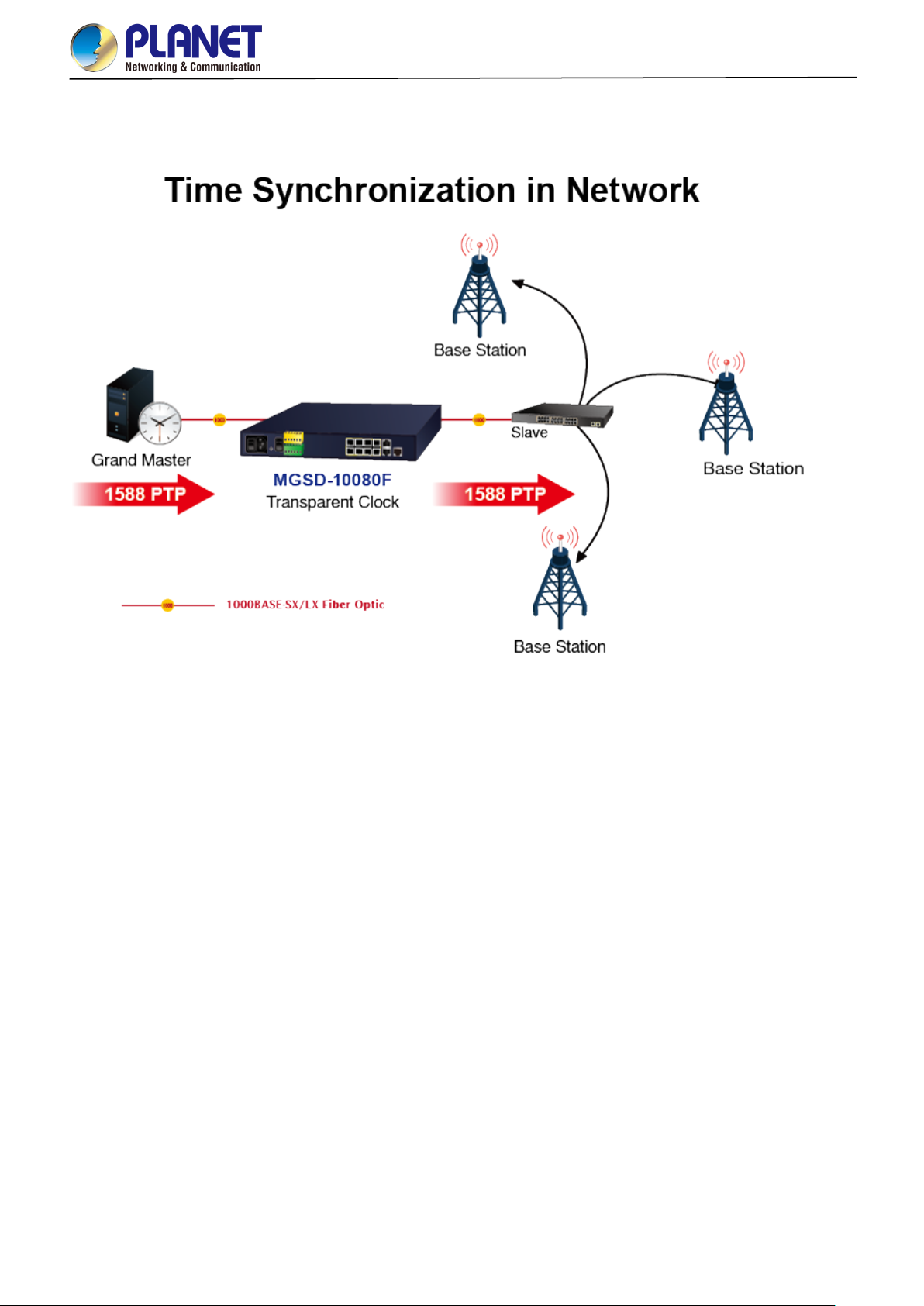
1588 Time Protocol for Industrial Computing Networks
The MGSD-10080F is ideal for telecom and Carrier Ethernet applications, supporting MEF service delivery and timing over
packet solutions for IEEE 1588 and synchronous Ethernet.
1.3 How to Use This Manual
This User’s Manual is structured as follows:
Section 2, INSTALLATION
The section explains the functi ons of the Managed Metro Switch and how to physically install the Managed Metro
Switch.
Section 3, SWITCH MANAGEMENT
The section contains the information about the software function of the Managed Metro Switch.
Section 4, WEB CONFIGURATION
The section explains how to manage the Managed Metro Switch by Web interface.
Section 5, SWITCH OPERATION
The chapter explains how to do the switch operation of the Managed Metro Switch.
Section 6, TROUBLESHOOTING
The chapter explains how to do troubleshooting of the Managed Metro Switch.
Appendix A
The section contains cab le inf or mat ion of the Managed Metro Switch.
Appendix B
The section contains glossary information of the Managed Metro Switch.
16
Page 17

User’s Manual of MGSD-10080F
1.4 Product Features
Physical Port
6 100/1000BASE-X SFP mini-GBIC slots (Port 1 to port 6)
2 100/1000/2500BASE-X mini-GBIC/SFP slots for SFP type auto detection(Port 7 to port 8)
2-Port 10/100/1000BASE-T Gigabit Ethernet RJ45 (Port 9 to port 10)
One RJ45 console interface for basic management and setup
Redundant Power System
Redundant Power System: 100V ~ 240V AC/Dual 36V ~ 60V DC
Active-active redundant power failure protection
Backup of catastrophic power failure on one supply
Fault tolerance and resilience.
Digital Input / Digital Output
2 Digital Input (DI)
2 Digital Output (DO)
Integrates sensors into auto alarm system
Transfer alarm to IP network via SNMP trap
Industrial Protocol
IEEE 1588v2 PTP (Precision Time Protocol) Transparent Clock mode
Hardware Design
-10 to 60 degrees C operating temperature for DC power input only
13-inch desktop size, 19-i nc h R ack-mountable
Relay alarm for port breakdown, power failure
Fanless design
Layer 2 Features
Prevents packet loss with back pressure (half-duplex) and IEEE 802.3x pause frame flow control (full-duplex)
High performance of Store-and-Forward architecture and runt/CRC filtering eliminate erroneous packets to optimize
the network bandwidth
Storm Control supp or t
− Broadcast / Multicast / Unicast
Supports VLAN
− IEEE 802.1Q tagged VLAN
− Up to 4K VLANs groups, out of 4094 VLAN IDs
− Supports provider bridging (VLAN Q-in-Q, IEEE 802.1ad)
− Private VLAN Edge (PVE)
− Port Isolation
− MAC-based VLAN
− IP Subnet-based VLAN
− Protocol-based VLAN
− VLAN Translat ion
− Voice VLAN
− GVRP
17
Page 18

User’s Manual of MGSD-10080F
Supports Spanning Tree Protocol
− STP, IEEE 802.1D Spanning Tree Protocol
− RSTP, IEEE 802.1w Rapid Spanning Tree Protocol
− MSTP, IEEE 802.1s Multiple Spanning Tree Protocol, spanning tree by VLAN
− BPDU Filtering/BPDU Guard
Supports Link Aggregation
− 802.3ad Link Aggregation Control Protocol (LACP)
− Cisco ether-channel (Static Trunk)
− Maximum 5 trunk groups, up to 8 ports per trunk group
− Up to 16Gbps bandwidth (Duplex Mode)
Provides port mirror (1-to-1)
Port mirroring to monitor the incoming or outgoing traf fic on a particular port
Loop protection to avoid broadcast loops
Supports ERPS (Ethernet Ring Protection Switching)
Compatible with Cisco Uni-directional link detection(UDLD) that monitors a link between two switches and blocks the
ports on both ends of the link if the link fails at any point between the two devices
Link Layer Discovery Protocol (LLDP) and LLDP-MED
Quality of Service
Ingress Shaper and Egress Rate Limit per port bandwidth control
8 priority queues on all switch ports
Traffic classification
- IEEE 802.1p CoS
- IP TOS / DSCP / IP Precedence
- IP TCP/UDP port number
- Typical network application
Strict priority and Weighted Round Robin (WRR) CoS policies
Supports QoS and In/Out bandwidth control on each port
Traffic-policing policies on the switch port
DSCP remarking
Multicast
Supports IPv4 IGMP Snooping v1, v2 and v3
Supports IPv6 MLD Snooping v1 and v2
Querier mode support
IGMP Snooping port filtering
MLD Snooping port filtering
MVR (Multicast VLAN Registration)
Security
Authentication
− IEEE 802.1x Port-based/MAC-based network access authentication
− Built-in RADIUS client to co-operate with the RADIUS servers
− TACACS+ login users access authentication
− RADIUS/TACACS+ users access authentication
18
Page 19

User’s Manual of MGSD-10080F
Access Control List
− IP-based Access Control List (ACL)
− MAC-based Access Control List
Source MAC/IP address binding
DHCP Snooping to filter un-trusted DHCP messages
Dynamic ARP Inspection discards ARP packets with invalid MAC address to IP address binding
IP Source Guard preven t s IP spoofing attacks
IP address access management to prevent unauthorized intruder
Management
IPv4 and IPv6 dual stack management
Switch Management Interfaces
- Web switch management
- Console/Telnet Command Line Interface
- SNMP v1 and v2c switch management
- SSHv2, TLSv1.2 and SNMP v3 se cu re a c ce ss
IPv6 IP Address/NTP/DNS management
Built-in Trivial File Transfer Protocol (TFTP) client
BOOTP and DHCP for IP address assignment
System Maintenance
− Firmware upload/download via HTTP/TFTP
− Configuration upload/download via HTTP/TFTP
− Reset button for system reboot or reset to factory default
− Dual Images
DHCP Relay
DHCP Option82
DHCP Server
User Privilege levels control
NTP (Network Time Protocol)
UPnP
Link Layer Discovery Protocol (LLDP) and LLDP-MED
Network Diagnostic
− SFP-DDM (Digital Diagnostic Monitor)
− ICMPv6/ICMPv4 Remote Ping
− Cable Diagnostic technology provides the mechanism to detect and report potential cabling issues
SMTP/Syslog remote alarm
Four RMON groups (history, statistics, alarms and ev ent s)
SNMP trap for interface Linkup and Linkdown notification
System Log
PLANET Smart Discovery Utility for deployment management
PLANET NMS system and CloudViewer for deployment management
19
Page 20
-36V DC @ 0.3A, Range: -36V ~ -60V DC
1G LNK/ACT (Green)
Throughput (packet per second)
1.5 Product Specifications
Product MGSD-10080F
Hardware Specificati ons
6 1000BASE-SX/LX/BX SFP interfaces, from port 1 to port 6
SFP Fiber Optic Ports
Compatible with 100BASE-FX SFP.
2 100/1000/2500BASE-X SFP interfaces, from port 7 to port 8
User’s Manual of MGSD-10080F
Copper Ports
Console 1 x RJ45 serial port (115200, 8, N, 1)
Reset Button
Power Requirements
Power Consumption
Alarm
DI/DO
ESD Protection
Dimensions (W x D x H)
Weight
LED
2 10/ 100/1000BASE-T RJ45 auto-MDI/MDI-X ports (Port-9 and Port-10)
< 5 sec: System reboot
> 5 sec: Factory default
AC 100~240V, 50/60Hz 0.15A
Max. 11.2 watts/38.2 BTU (AC input)
Max. 10.8 watts/36.9 BTU (DC input)
One relay output for power failure. Alarm Relay current carry ability: 1A @ DC 24V
2 Digital Input (DI): Level 0: -24V~2.1V (±0.1V)
Level 1: 2.1V~24V (±0.1V)
Input Load to 24V DC, 10mA max.
2 Digital Output (DO): Open collector to 24VDC, 100mA max.
6KV DC
330 x 155 x 43.5 mm, 1U high
1661g
System:
PWR (Green)
DC 1 (Green)
DC 2 (Green)
Fault Alarm (Green)
Ring (Green)
Ring Owner (Green)
Per Gigabit SFP Ports: Port 1 to Port 6.
100 LNK/ACT (Orange)
1G LNK/ACT (Green)
Per Gigabit SFP Ports: Port 7 to Port 8.
100 LNK/ACT (Orange)
1G/2.5G LNK/ACT (Green)
Per Gigabit RJ45 Ports: Port 9 to Port 10.
10/100 LNK/ACT (Orange)
Switching
Switch Architecture Store-and-Forward
Switch Fabric
Address Table 8K entries, automatic source address learning and aging
SDRAM
26Gbps/non-blocking
19.3Mpps @ 64Bytes packet
256Mbits
20
Page 21

Ring
Flash
User’s Manual of MGSD-10080F
64Mbytes
Flow Control
Jumbo Frame 9KB
Layer 2 Functions
Port Configuration
Port Status
Port Mirroring
VLAN
IEEE 802.3x pause frame for full-duplex
Back pressure for half-duplex
Port disable / enable
Auto-Negotiation 10/100/1000Mbps full and half duplex mode selection
Flow Control disable / enable
Bandwidth control on each port
Power saving mode control
Display each port’s speed duplex mode, link status, flow control status,
auto negotiation status, trunk status
TX/RX/Both
1 to 1 monitor
802.1Q tag-based VLAN
Q-in-Q tunneling
Private VLAN Edge (PVE)
MAC-based VLAN
Protocol-based VLAN
VLAN Translat ion
Voice VLAN
MVR (Multicast VLAN Registration)
GVRP
Up to 4K VLAN groups, out of 4094 VLAN IDs
Link Aggregation
Spanning Tree Protocol
QoS
IGMP Snooping
MLD Snooping
Bandwidth Control
IEEE 802.3ad LACP/Static Trunk
Supports 5 groups of 8-Port trunk sup port
IEEE 802.1D Spanning Tree Protocol
IEEE 802.1w Rapid Spanning Tree Protocol
IEEE 802.1s Multiple Spanning Tree Protocol
Traffic classification based, strict priority and WRR
8-level priority for switching
- Port number
- 802.1p priority
- 802.1Q VLAN tag
- DSCP/TOS field in IP packet
Supports ERPS, and complies with ITU-T G.8032
IGMP (v1/v2/v3) Snooping, up to 255 multicast groups
IGMP Querier mode support
MLD (v1/v2) Snooping, up to 255 multicast groups
MLD Querier mode support
Per port bandwidth control
Ingress: 500Kb~1000Mbp s
Egress: 500Kb~1000Mbps
Security Functions
Access Control List
IP-based ACL/MAC-based ACL
ACL based on:
- MAC Address
21
Page 22

Local/RADIUS authentication
- IP Address
- Ethertype
- Protocol Type
- VLAN ID
- DSCP
- 802.1p Priority
Up to 123 entries
Port Security
Security
AAA
Network Access Control
Switch Management Functions
Basic Management Interfaces Console; Telnet; Web Browser; SNMP v1, v2c
IP source guard
Dynamic ARP inspection
Command line authority control based on user lev el
RADIUS client
TACACS+ client
IEEE 802.1x port-based network access control
MAC-based authentication
User’s Manual of MGSD-10080F
Secure Management Interfac es SSHv2, TLS v1.2, SNMP v3
Firmware upgrade by HTTP protocol through Ethernet network
Configuration upload/download through HTTP
Remote Syslog
System log
System Management
Event Management
SNMP MIBs
LLDP protocol
NTP
PLANET Smart Discovery Utility
PLANET NMS system and CloudViewer
Remote Syslog
Local System log
SMTP
RFC 1213 MIB-II
RFC 2863 IF-MIB
RFC 1493 Bridge MIB
RFC 1643 Ethernet MIB
RFC 2863 Interface MIB
RFC 2665 Ether-Like MIB
RFC 2737 Entity MIB
RFC 2819 RMON MIB (Groups 1, 2, 3 and 9)
RFC 2618 RADIUS Client MIB
RFC 3411 SNMP-Frameworks-MIB
IEEE 802.1X PAE
LLDP
MAU-MIB
Standards Conformance
Regulatory Compliance FCC Part 15 Class A, CE
Standards Compliance
IEEE 802.3 10BASE-T
IEEE 802.3u 100BASE-TX/100BASE-FX
IEEE 802.3ab Gigabit 1000T
IEEE 802.3z Gigabit SX/LX
22
Page 23

Relative Humidity: 5 ~ 95% (non-condensing)
Environments
Operating
Storage
User’s Manual of MGSD-10080F
IEEE 802.3bz 2.5GBASE-X
IEEE 802.3x flow control and back pressure
IEEE 802.3ad port trunk with LACP
IEEE 802.1D Spanning Tree Protocol
IEEE 802.1w Rapid Spanning Tree Protocol
IEEE 802.1s Multiple Spanning Tree Protocol
IEEE 802.1p Class of Service
IEEE 802.1Q VLAN tagging
IEEE 802.1ad Q-in-Q VLAN stacking
IEEE 802.1X Port Authentication Network Control
IEEE 802.1ab LLDP
IEEE 802.3ah OAM
IEEE 802.1ag Connectivity Fault Management (CFM)
RFC 768 UDP
RFC 793 TFTP
RFC 791 IP
RFC 792 ICMP
RFC 2068 HTTP
RFC 1112 IGMP v1
RFC 2236 IGMP v2
RFC 3376 IGMP version 3
RFC 2710 MLD version 1
RFC 3810 MLD version 2
ITU-T G.8032 ERPS Ring
ITU-T Y.1731 Performance Monitoring
Temperature: -10 ~ 60 degrees C for DC power input
0 ~ 50 degrees C for AC power input
Relative Humidity: 5 ~ 95% (non-condensing)
Temperature: -10 ~ 70 degrees C
23
Page 24

User’s Manual of MGSD-10080F
should be active all the time, please consider using UPS (Uninterrupted Power Supply) for your device.
2. INSTALLATION
2.1 Hardware Description
This section describes the hardware features and installation of the Managed Metro Switch on the desktop or rack mount. For
easier management and control of the Managed Metro Switch, familiarize yourself with its display indicators, and ports. Front
panel illustrations in this chapter display the unit LED indicators. Before connecting any network device to the Managed Metro
Switch, please read this chapter completely.
2.1.1 Switch Front Panel
The front panel provides a simple interface monitoring the Managed Metro Switch. Figure 2-1 show the front panel.
Front Panel
Figure 2-1: MGSD-10080F Front Panel
■ AC Power Receptacle
For compatibility with electric service in most areas of the world, the Managed Metro Switch’s power supply automatically
adjusts to line power in the range of 100-240V AC and 50/60 Hz.
Plug the female end of the power cord firmly into the receptalbe on the front panel of the Managed Metro Switch. Plug the
other end of the power cord into an electric service outlet and then the power will be ready.
The device is a power-required device, which means it will not work till it is powered. If your networks
Power Notice:
■ DC Power Connector
The front panel of the M anaged M etr o Switch contains a power sw itch and a DC pow er con nector, which accepts DC power
input voltage from -3 6V t o -60V DC. Connect the pow er ca bl e to the Managed Metro Sw itc h at the input terminal bloc k. The
size of the two screws in the terminal block is M3.5.
■ Digital Input
It will prevent you from network data loss or network downtime. In some areas, installing a surge
suppression device may also help to protect your Managed Metro Switch from being damaged by
unregulated surge or current to the Switch or the power adapter.
The digitail input of the Managed Metro Switch can be activated by the external sensor that senses physical changes.
These changes can includ e int rusion de tec tion or cert ain p hysical change in th e monit ored ar ea. For ex amples, t he ex ternal
sensor can be a door switch or an infrared motion detector.
■ Digital Output
The digital output main function is to allow the Managed Metro Switch to trigger external devices, either automatically or by
remote control from a human operator or a software application.
24
Page 25

User’s Manual of MGSD-10080F
Reset Button Pressed and Released
Function
192.168.0.254
■ 100/1000BASE-X SFP Slots (port 1 to port 6)
Each of the SFP (Small Form-factor Pluggable) s lot sup ports dual-speed, 1000BASE-SX/LX or 100BASE-FX
- For 1000BASE-SX/LX SFP transceiver module: From 550 meters (multi-mode fiber) to 10/20/40/60/80/120
kilometers (single-mode fiber).
- For 100BASE-FX SFP transceiver module: From 2 kilometers (multi-mode fiber) to 20/40/60 kilometers
(single-mode fiber).
■ 100/1000/2500BASE-X SFP Slots (port 7 to port 8)
Each of the SFP (Small Form-factor Pluggable) slot supports triple-speed, 2500BASE-X,1000BASE-SX/LX or
100BASE-FX
- For 2500BASE-X SFP transceiver module: From 330 meters (multi-mode fiber) to 2/20kilometers
(single-mode fiber).
- For 1000BASE-SX/LX SFP transceiver module: From 550 meters (multi-mode fiber) to 10/20/40/60/80/120
kilometers (single-mode fiber).
- For 100BASE-FX SFP transceiver module: From 2 kilometers (multi-mode fiber) to 20/40/60 kilometers
(single-mode fiber).
■ Gigabit TP Interface(port 9 to port 10)
10/100/1000BASE-T Copper, RJ45 twisted-pair: Up to 100 meters.
■ Console Port
The console port is an RJ45 port connector. It is an interface for connecting a terminal directly. Through the console port, it
provides rich diagnostic information including IP Address setting, factory reset, port management, link status and system
setting. Users can use the attached DB9 to RJ45 console cable in the package and connect to the console port on the
device. Af ter the con nec tio n, users can run any terminal emulation program (Hyper Terminal, ProComm Plus, Telix,
Winterm and so on) to enter the startup screen of the device.
■ Reset Button
In the middle of the front p an el, the reset button i s d esi gne d f or reb oot ing the M anaged Metro Switch witho ut t ur ning off and
on the power. The following is the summary table of Reset button function:
Reset the Managed Metro Switch to Factory Default
configuration. The Managed Metro Switch will then reboot
and load the default settings as shown below:
< 5 seconds: Switch Reboot
> 5 seconds: Factory Default
。 Default Username: admin
。 Default Password: admin
。 Default IP address: 192.168.0.100
。 Subnet mask: 255.255.255.0
。 Default Gateway:
Figure 2-2: MGSD-10080F Reset Button
25
Page 26

at the spee d of
2.1.2 LED Indicators
LED Definition
System
LED Color Function
User’s Manual of MGSD-10080F
PWR Green
DC1 Green
DC2 Green
Alarm Green
Lights to indicate that the Managed Metro Switch is powered on by AC input.
Lights to indicate that the Managed Metro Switch is powered on by DC1 input.
Lights to indicate that the Managed Metro Switch is powered on by DC2 input.
Lights to indicate that Managed Metro Switch AC/DC or port has failed.
Ring Green Lights to indicate that the ERPS Ring has been created successfully.
R.O Green Lights to indicate that Switch Ring Owner has been enabled.
Per 100/1000 SFP Interface (Port 1 to port 6)
LED Color Function
Lights: To indicate the link through that port i s su cce ssfully establi shed at the speed of
1000Mbps.
1000
LNK/ACT
Green
Blink: To indicate that the switch is actively sending or receiving data over that port.
Off: If 1000 LNK/ACT LED is lit, it indicates the port is operating at 1000Mbps.
100
LNK/ACT
Orange
If 1000 LNK/ACT LED is off, it indicates that the port is link down or operating at
100Mbps.
Lights: To indicate the link through that port is successfully established
100Mbps.
Blink: To indicate that the switch is actively sending or receiving data over that port.
Off: If 100 LNK/ACT LED is lit, it indicates the port is operating at 100Mbps
If 100 LNK/ACT LED is off, it indicates that the port is link down or operating at
1000Mbps.
26
Page 27

1000Mbps or
at the spee d of
at the speed of
operating at
at the speed of
Per 100/1000/2500 SFP Interface (Port 7 to port 8)
LED Color Function
Lights: To indicate the link through that port i s su cce ssfully establi shed at the speed of
1000Mbps or 2500Mbp s.
Blink: To indicate that the switch is actively sending or receiving data over that port.
1G/2.5G
LNK/ACT
Green
Off: If 1G/2.5G LNK/ACT LED is lit, it indicates the port is operating at
2500Mbps.
If 1G/2.5G LNK/ACT LED is off, it indicates that the port is link down or
operating at 100Mbps.
Lights: To indicate the link through that port is successfully established
100Mbps.
User’s Manual of MGSD-10080F
100
LNK/ACT
Per 10/100/1000BASE-T Interface (Port 9 to port 10)
LED Color Function
1000
LNK/ACT
Orange
Green
Blink: To indicate that the switch is actively sending or receiving data over that port.
Off: If 100 LNK/ACT LED is lit, it indicates that the port is operating at 100Mbps
If 100 LNK/ACT LED is off, it indicates the port is link down or operating at
1000Mbps or 2500Mbp s.
Lights: To indicate the link through that port is successfully esta bl i shed
1000Mbps.
Blink: To indicate that the switch is actively sending or receiving data over that port.
Off: If 1000 LNK/ACT LED is lit, it indicates the port is operating at 1000Mbps.
If 1000 LNK/ACT LED i s of f, it indicates that the port i s link down or
10/100Mbps .
Lights: To indicate the link through that port is successfully established
10Mbps or 100Mbps.
10/100
LNK/ACT
Orange
Blink: To indicate that the switch is actively sending or receiving data over that port.
Off: If 10/1 00 LNK/AC T LED is lit, it indicates the port is operating at 10/100Mbps.
If 10/100 LNK/ACT LED is off, it indicates the port is link down or operating at
1000Mbps.
27
Page 28

User’s Manual of MGSD-10080F
2.1.2 Wiring the AC Power Input
The front panel of the MGSD-10080F indicates an AC inlet power socket, which accepts input power from 100 to 240V AC,
50/60Hz.
28
Page 29
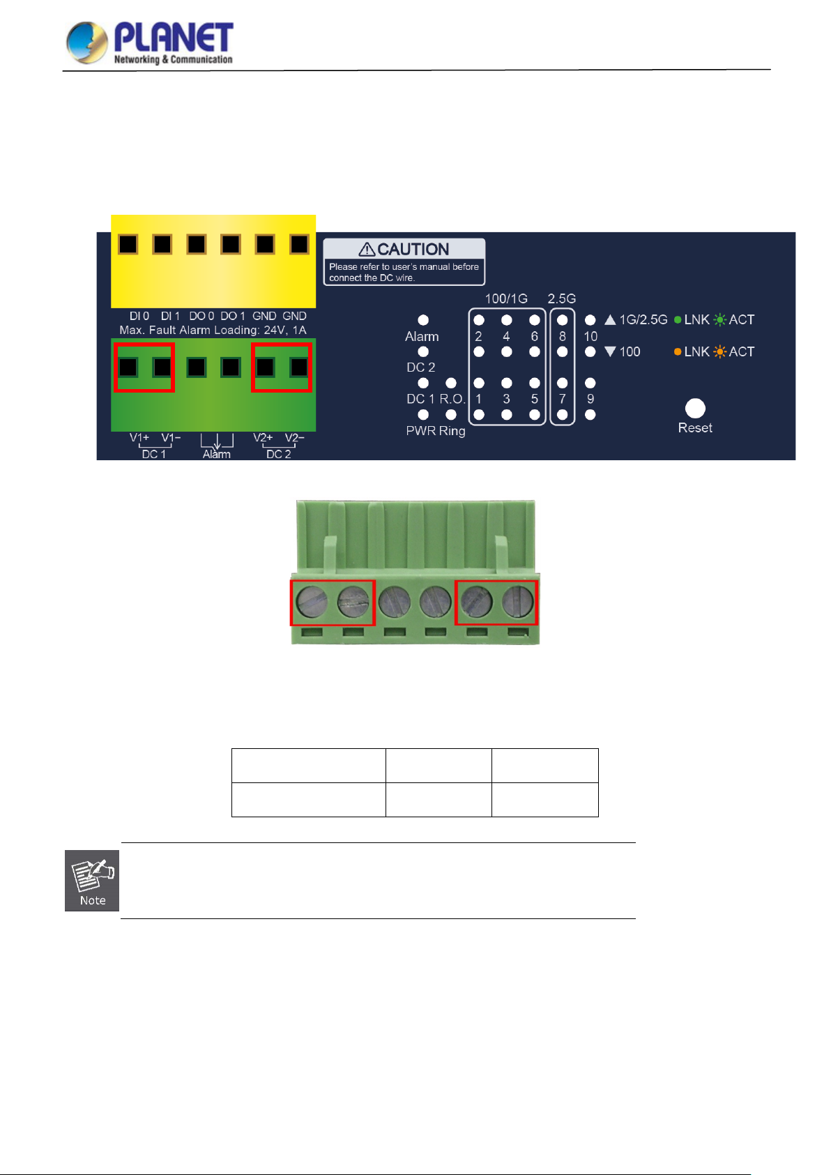
User’s Manual of MGSD-10080F
2.1.3 Wiring the DC Power Input
The Front Panel of the Managed Metro Switch indicates a DC inlet power socket and consists of one terminal block conn ector
within 6 contacts. Please follow the steps below to insert the power wire.
1. Insert positive/negative DC power wires into the contacts 1 and 2 for DC POWER 1, or 5 and 6 for DC POWER 2.
2. Tighten the wire-clamp screws for preventing the wires from loosening.
1 2 3 4 5 6
V1+ V1- V2+ V2-
DC Power 1 DC Power 2
Positive (+) Pin Negative (-) Pin
Managed Metro Switch Pin 1 / 5 Pin 2 / 6
The wire gauge for the terminal block should be in the range from 12 to 24 AW G.
29
Page 30

User’s Manual of MGSD-10080F
2.1.4 Wiring the Fault Alarm Contact
The fault alarm contac t s are in the middl e (3 & 4) of the t ermin al block conne ctor as the pict ure show s below. Inserting the wires,
the Managed Metro Switch will detect the f a ult st atus of the power failure, or port link failure (av ailab le for managed model). The
following illustration shows an application example for wiring the fault alarm contacts.
Insert the wires into the fault alarm contacts
1. The wire gauge for the terminal block should be in the range from 12 to 24 AW G.
2. When performing any of the procedures like inserting the wires or tightening the wire-clamp screws,
make sure the power is OFF to prevent from getting an electric sho ck.
2.1.5 Wiring the Digital Input/Output
The 6-contact terminal block connector on the front panel of Managed Metro Switch is used for Digital Input and Digital Output.
Please follow the steps below to insert wire.
1. The Managed Metro Switch offers two DI and DO groups. 1 and 2 are DI groups, 3 and 4 are DO groups and 5 and 6 are
GND (ground).
Figure 2-3: Wiring the Digital Input/Digital Output and Ground
30
Page 31

User’s Manual of MGSD-10080F
2. Tighten the wire-clamp screws for preventing the wires from loosening.
1 2 3 4 5 6
DI0 DI1 DO0 DO1 GND GND
Figure 2-4: 6-pin Terminal Block for DI and DO Wiring Input
3. There are two Digital Input groups for you to monitor two different devices. The following topology shows how to wire DI0
and DI1.
Figure 2-5: Wiring DI0 and DI1 to Open Detector
31
Page 32

User’s Manual of MGSD-10080F
4. There are two Digital Output groups for you to sense Managed Metro Switch port failure or power failure and issue a high
or low signal to external device. The following topology shows how to wire DO0 and DO1.
Figure 2-6: Wiring DO0 and DO1 to Open Detector
32
Page 33

User’s Manual of MGSD-10080F
h RJ45 tips. For
2.2 Installing the Managed Metro Switch
This section describes how to install your Managed Metro Switch and make con nec tion s to the Manag ed Metro Swit ch .
Please read the following topics and perform the procedures in the order being presented. To install your Managed Metro
Switch on a desktop or shelf, simply comp lete the foll owing steps.
In this paragraph, we will describe how to install the Managed Metro Switch and the installation points attended to it.
2.2.1 Desktop Installation
To install the Managed Metro Switch on desktop or shelf, please follow these steps:
Step 1: Attach the rubber feet to the recessed areas on the bottom of the Managed Metro Switch.
Step 2: Place the Managed Metro Switch on the desktop or the shelf near an AC/DC power source as shown in Figure 2-7.
Figure 2-7: Place the Managed Metro Switch on the Desktop
Step 3: Keep enough ventilation space between the Managed Metro Switch and the surrounding objects.
Step 4: Connect the Managed Metro Switch to network devices.
Connect one end of a standard network cable to the 10/100/1000 RJ45 ports on the front of the Managed Metro Switch.
Connect the other end of the cable to the network devices such as printer servers, workstations or routers, etc.
Connecting to the Managed Metro Switch requires UTP Category 5 network cabling wit
more information, please see the Cabling Specification in Appendix A.
Step 5: Supply power to the Managed Metro Switch.
Connect one end of the power cable to the Managed Metro Switch.
Connect the power plug of the power cable to a standard wall outlet.
When the Managed Metro Switch receives power, the Power LED should remain solid Green.
33
Page 34
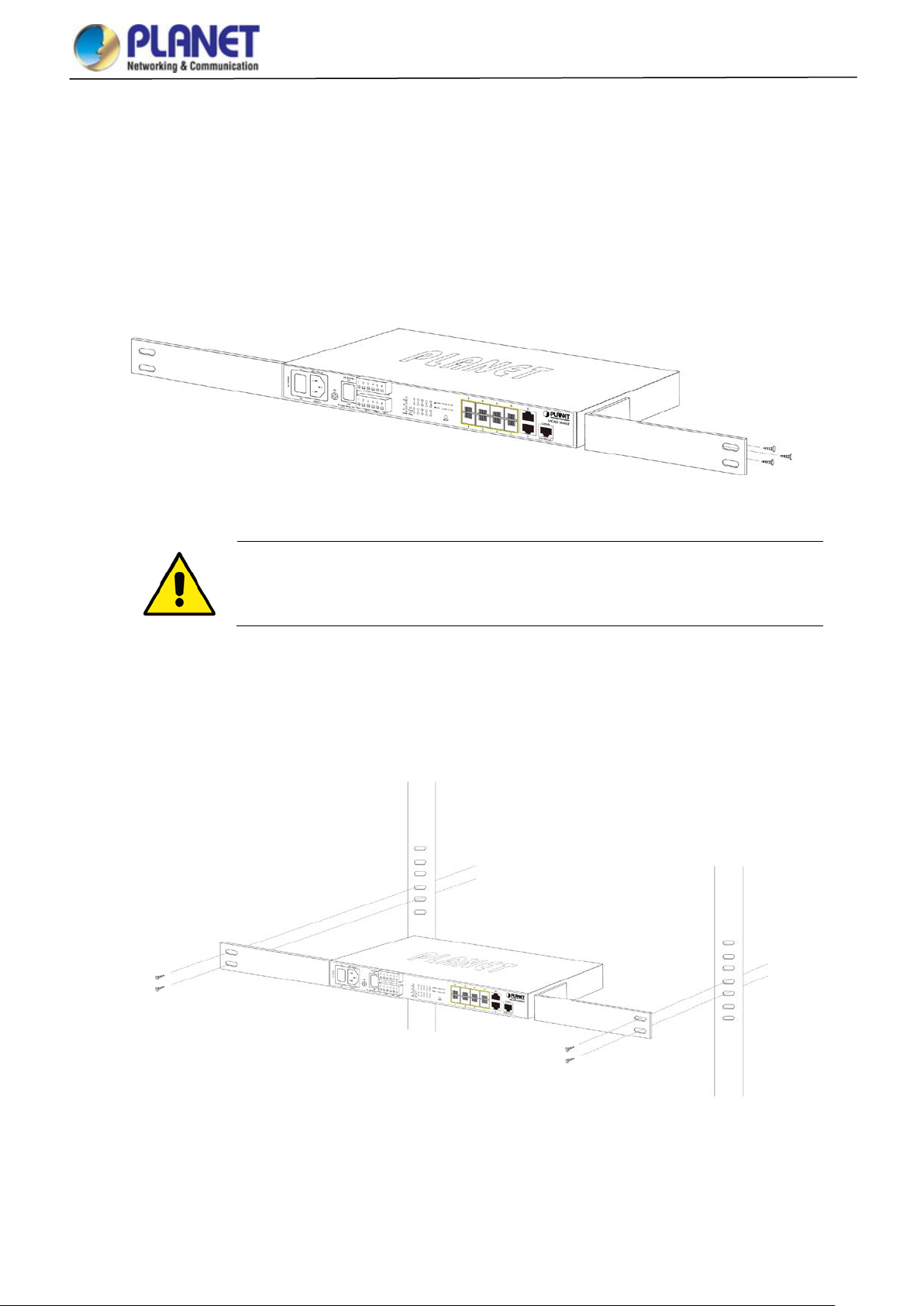
User’s Manual of MGSD-10080F
You must use the screws supplied with the mounting brackets. Damage caused to the parts by
2.2.2 Rack Mounting
To install the Managed Metro Switch in a 19-inch standard rack, please follow the instructions described below.
Step 1: Place the Managed Metro Switch on a hard flat surface, with the front panel positioned towards the front side.
Step 2: Attach the rack-mount bracket to each s ide of t he M anaged Metro Switch with supplied screw s attac hed to th e pa ckage .
Figure 2-8 shows how to attach brackets to one side of the Managed Metro Switch.
Figure 2-8: Attach Brackets to the Managed Metro Switch.
using incorrect screws would invalidate the warranty.
Step 3: Secure the brackets tightly.
Step 4: Follow the same steps to attach the second bracket to the opposite side.
Step 5: After the brac kets are attached to the Managed Metro Switch, use suitable screws to securely attach the brackets to the
rack as shown in Figure 2-9.
Figure 2-9: Mounting the Managed Metro Switch on a Rack
Step 6: Proceeds with steps 4 and 5 of session 2.2.1 Desktop Installation to connect the network cabling and supply power to
the Managed Metro Switch.
34
Page 35

User’s Manual of MGSD-10080F
Port Type
Cable Type
Connector
50/125µm or 62.5/125µm multi-mode 9/125µm single-mode
2.3 Cabling
10/100/1000BASE-T
All 10/100/1000BASE-T ports come with auto-negotiation capability. They automatically support 1000BASE-T,
100BASE-TX and 10BASE-T networks. Users only need to plug a working network device into one of the
10/100/1000BASE-T ports, and then turn on the Managed Metro Switch. The port will automatically run at 10Mbps,
20Mbps, 100Mbps or 200Mbps and 1000Mbps or 2000Mbps after negotiating with the connected device.
100BASE-FX/1000BASE-SX/LX/2500BASE-X
The Managed Metro Switch has eight SFP interfaces that support 100/1000/2500Mbps triple speed mode (optional
multi-mode/single-mode 100BASE-FX/1000BASE-SX/LX/2500BASE-X SFP module)
Interface/SFP Mode 100BASE-FX 1000BASE-SX/LX 2500BASE-X
Port 1 to Port 6
Port 7 to Port 8
Cabling
Each 10/100/1000BASE-T port uses an RJ45 socket -- s imilar to phone j acks -- for connection of unshielded twisted-pair
cable (UTP). The IEEE 802.3/802.3u 802.3ab Fast/Gigabit Ethernet standard requires Category 5 UTP for 100Mbps
100BASE-TX. 10BASE-T networks can use Cat.3, 4, 5 or 1000BASE-T use 5/5e/6 UTP (see table below). Maximum
distance is 100 meters (328 feet). The 100BASE-FX/1000BASE-SX/LX/2500BASE-X SFP slot uses an LC connector with
optional SFP module. Please see table below and know more about the cable specifications.
10BASE-T Cat3, 4, 5, 2-pair RJ45
100BASE-TX Cat5 UTP, 2-pair RJ45
1000BASE-T Cat5/5e/6 UTP, 2-pair RJ45
100BASE-FX
1000BASE-SX/LX
2500BASE-X
50/125µm or 62.5/125µm multi-mode 9/125µm single-mode
50/125µm or 62.5/125µm multi-mode 9/125µm single-mode
● ●
● ● ●
LC (multi/single mode)
LC (multi/single mode)
LC (multi/single mode)
NA
Any Ethernet devices like hubs and PCs can connect to the Managed Metro Switch by using straight-through wires. The
two 10/100/1000Mbps ports are auto-MDI/MDI-X and can be used on straight-through or crossover cable.
35
Page 36

User’s Manual of MGSD-10080F
Interface
Operating Temp.
2.3.1 Installing the SFP Transceiver
The sections describe how to insert an SFP transceiver into an SFP slot.
The SFP transceivers are hot-pluggable and hot-swappable. You can plug in and out the transceiver to/from any SFP port
without having to power down the Managed Metro Switch as Figure 2-10 shows below:
Figure 2-10: Plugging in the SFP Transceiver
Approved PLANET SFP Transceivers
PLANET Managed Metro Switch supports both single mode and multi-mode SFP transceivers. The following list of
approved PLANET SFP transceivers is correct at the time of publication:
Fast Ethernet Transceiver (100BASE-X SFP)
Model DDM Speed (Mbps)
MFB-FX -- 100 LC Multi Mode 2km 1310nm
MFB-F20 -- 100 LC Single Mode 20km 1310nm
MFB-F40 -- 100 LC Single Mode 40km 1310nm
MFB-F60 -- 100 LC Single Mode 60km 1310nm
MFB-F120 -- 100 LC Single Mode 120km 1550nm
Connector
Interface
Fiber Mode Distance Wavelength (nm)
Operating
Temp.
0 ~ 60 ℃
0 ~ 60 ℃
0 ~ 60 ℃
0 ~ 60 ℃
0 ~ 60 ℃
Fast Ethernet Transceiver (100BASE-BX, Single Fiber Bi-directional SFP)
Model DDM Speed (Mbps)
MFB-FA20
MFB-FB20
Connector
-- 100 WDM(LC) Single Mode 20km 1310nm 1550nm
-- 100 WDM(LC) Sing le Mod e 20km 1550nm 1310nm
Fiber Mode Distance Wavelength (TX) Wavelength (RX)
0 ~ 60 ℃
0 ~ 60 ℃
36
Page 37

Connector
Interface
Connector
Interface
Interface
RX:1550nm
Gigabit Ethernet Transceiver (1000BASE-X SFP)
User’s Manual of MGSD-10080F
Model DDM Speed (Mbps)
MGB-GT -- 1000 Copper -- 100m --
MGB-SX(V2) YES 1000 LC Multi Mode 550m 850nm
MGB-SX2(V2) YES 1000 LC Multi Mode 2km 1310nm
MGB-LX(V2) YES 1000 LC Single Mode 20km 1310nm
MGB-L40 YES 1000 LC Single Mode 40km 1310nm
MGB-L80 YES 1000 LC S ingle Mode 80km 1550nm
MGB-L120(V2) YES 1000 LC Single Mode 120km 1550nm
Fiber Mode Distance Wavelength (nm) Operating Temp.
Gigabit Ethernet Transceiver (1000BASE-BX, Single Fiber Bi-directional SFP)
Model DDM Speed (Mbps)
MGB-LA10(V2)
YES
MGB-LB10(V2)
MGB-LA20(V2)
YES
MGB-LB20(V2)
1000 WDM(LC) Single Mode 10km 1310nm 1550nm
1000 WDM(LC) Single Mode 10km 1550nm 1310nm
1000 WDM(LC) Single Mode 20km 1310nm 1550nm
1000 WDM(LC) Single Mode 20km 1550nm 1310nm
Fiber Mode Distance Wavelength (TX) Wavelength (RX) Operating Temp.
0 ~ 60 ℃
0 ~ 60 ℃
0 ~ 60 ℃
0 ~ 60 ℃
0 ~ 60 ℃
0 ~ 60 ℃
0 ~ 60 ℃
0 ~ 60 ℃
0 ~ 60 ℃
0 ~ 60 ℃
0 ~ 60 ℃
MGB-LA40(V2)
YES
MGB-LB40(V2)
MGB-LA80
YES
MGB-LB80
1000 WDM(LC) Single Mode 40km 1310nm 1550nm
1000 WDM(LC) Single Mode 40km 1550nm 1310nm
1000 WDM(LC) Single Mode 80km 1490nm 1550nm
1000 WDM(LC) Single Mode 80km 1550nm 1490nm
Gigabit Ethernet Transceiver (2500BASE-X SFP)
Model DDM Speed (Mbps)
Connector
Fiber Mode Distance Wavelength (nm) Operating Temp.
MGB-2GSR YES 2500 LC Multi Mode 300m 850nm
MGB-2GLR2 YES 2500 LC Single Mode 2km 1310nm
MGB-2GLR20 YES 2500 LC Single Mode 20km 1310nm
MGB-2GLA20
MGB-2GLB20
YES
YES
2500
2500
LC
LC
Single Mode 20km
Single Mode 20km
TX:1310nm
TX:1550nm
RX:1310nm
It is recommended to use PLANET SFP on the Managed Metro Switch. If you insert an SFP
transceiver that is not supported, the Managed Metro Switch will not recognize it.
0 ~ 60 ℃
0 ~ 60 ℃
0 ~ 60 ℃
0 ~ 60 ℃
0 ~ 70 ℃
0 ~ 70 ℃
0 ~ 70 ℃
0 ~ 70 ℃
0 ~ 70 ℃
Connect the fiber cable
1. Attach the duplex LC connector on the network cable to the SFP transceiver.
2. Connect the other end of the cable to a device – switches with SFP installed, fiber NIC on a workstation or a media
converter.
3. Check the LNK/ACT LED of the SFP slot on the front of the Managed Metro Switch. Ensure that the SFP transceiver is
operating correctly.
37
Page 38

User’s Manual of MGSD-10080F
position. Directly pulling out the module could damage the module and the SFP module slot of the
2.3.2 Removi ng t he SFP Transceiver
1. Make sure there is no netw ork activity by ch ecking w ith the ne twor k administr ator, or through the management interf ace of
the switch/converter (if available) to disable the port in advance.
2. Remove the Fiber Optic Cable gently.
3. Lift up the lever of the MFB/MGB series SFP module and turn it to a horizontal position.
4. Pull out the module gently through the lever.
Figure 2-11: How to Pull Out the SFP Transceiver Module
Never pull out the module without lifting up the lever of the module and turning it to a horizontal
Managed Metro Switch.
38
Page 39

User’s Manual of MGSD-10080F
to access the Managed Metro Switch. If the W eb
virus software or firewall and
3. SWITCH MANAGEMENT
This chapter explains the methods that you can use to configure management access to the Managed Metro Switch. It
describes the types of management applicati ons and the co m muni cat ion and ma nage men t protocols that deliver data between
your management device ( w or kstation or personal comp uter ) and the system. It also contains information a bout port connection
options.
This chapter covers the following topics:
Requirements
Management Acces s Overview
Remote Telnet Access
Web Management Access
SNMP Acce ss
Standards, Protocols, and Related Reading
3.1 Requirements
Workstations running Windows XP/2003/2008/2012/Vista/7/8/10, MAC OS X or later, Linux, UNIX, or other
platforms are compatible with TCP/IP protocols.
Workstations are installed with Ethernet NIC (Network Interface Card)
Serial Port Connection (Terminal)
The above workstation s com e w it h COM port (DB9) or USB-to-RS232 converter.
The above workstations have been installed with terminal emulator, su ch as Tera Term, PuTTY or Hyper
Terminal included in Windows XP/2003.
Serial cable -- one end is attached to the RS232 serial port, while the other end to the console port of the
Managed Metro Switch.
Ethernet Port Connection
Network cables -- Use standard network (UTP) cables with RJ45 connectors.
The above PC is installed with Web browser.
It is recommended to use Internet Explorer 8.0 or above
interface of the Managed Metr o Switch is not accessible, please turn off the antithen try it again.
39
Page 40

User’s Manual of MGSD-10080F
3.2 Management Access Overview
The Managed Metro Switch gives you the flexibility to access and manage it using any or all of the following methods:
Remote Telnet Interface
Web browser Interface
An external SNMP-based network management application
The remote Telnet and Web browser interfaces are embedded in the Mana ged Metro Switch software and are available for
immediate use. Each of these management methods has their own advantages. Table 3-1 compares the three management
methods.
Method Advantages Disadvantages
Console
Remote
Telnet
Web Browser
• No IP address or subnet needed
• Text-based
• Telnet functionality and HyperTerminal
built into Windows
95/98/NT/2000/ME/XP operating
systems
• ProcommPlus, putty, tera term
• Secure
• Text-based
• Telnet functionality built into Windows
XP/2003, Vista, Windows 7 operating
systems
• Can be accessed from any location
• Ideal for configuring the switch remotely
• Compatible with all popular browsers
• Can be accessed from any location
• Most visually appealing
• Must be near the switch or use dial-up
connection
• Not convenient for remote users
• Modem connection may prove to be unreliable
or slow
• Security can be compromised (hackers need
only know the IP address)
• Security can be compromised (hackers need
only know the IP address and subnet mask)
• May encounter lag times on poor connections
SNMP Agent
• Communicates with switch functions at
the MIB level
• Based on open standards
Table 3-1: Management Methods Comparison
• Requires SNMP manager software
• Least visually appealing of all three methods
• Some settings require calculations
• Security can be compromised (hackers need
only know the community name)
40
Page 41

User’s Manual of MGSD-10080F
3.3 CLI Mode Management
There are two ways for CLI mode management, one is remote telnet and the other operated fr om conso le p or t. Remote telnet is
an IP-based protocol and console port is for user to operate the Managed Metro Switch locally only; however, their operations
are the same.
The command line user interface is for performing system administration, such as displaying statistics or changing option
settings. When this method is used, you can access the Managed Metro Switch remote telnet interface from personal
computer, or workstation in the same Ethernet environment as long as you know the current IP address of the Managed Metro
Switch.
Direct Access
Direct access to the administration console is achieved by directly connecting a terminal or a PC equipped with a
terminal-emulation program (such as HyperTerminal, ProcommPlus, putty, tera term) to the Managed Metro Switch console
(serial) port. When using this management method, a straight DB9 RS-232 cable is required to connect the switch to the PC.
After making this connection, configure the terminal-emulation program to use the following parameters:
The default parameters are:
115200 bps baud rate
8 data bits
No parity
1 stop bit
41
Page 42

User’s Manual of MGSD-10080F
You can change these settings, if desired, after you log on. This management method is often preferred because you can
remain connected and monitor the system during system reboots. Also, certain error messages are sent to the serial port,
regardless of the interface through which the associated action was initiated. A Macintosh or PC attachment can use any
terminal-emulation progra m f or con necting to t he termi nal ser ial por t. A workstation attachm ent und er UNI X can use an emulator
Remote Telnet
In Windows system, you may click “Start” and then choose “Accessories” and “Command Prompt”. Please input “telnet
192.168.0.100” and press “enter’ from your keyboard. You will see the following screen appears as Figure 3-2 shows.
Figure 3-1: Remote Telnet Interface Main Screen of Managed Metro Switch
42
Page 43

User’s Manual of MGSD-10080F
3.4 Web Management
The Managed Metro Switch offers management features that allow users to manage the Managed Metr o Switch from
anywhere on the network through a standard browser such as Microsoft Internet Explorer. After you set up your IP address for
the Managed Metro Switch, you can access the Ma naged Metr o S witch ’s Web interface applications directly in your Web
browser by entering the IP address of the M anag ed Metro S witch.
Figure 3-2: Web Management
You can then use your Web browser to list and manage the Managed Metro S witch configuration parameters from one central
location; the Web Management requires Micr o soft Internet Explorer 8.0 or later.
Figure 3-3: Web Main Screen of Managed Metro Switch
43
Page 44

User’s Manual of MGSD-10080F
3.5 SNMP-based Network Management
You can use an external SNMP-based application to configure and manage the Managed Metro Switch, such as SNMP
Network Manager, HP Openview Network Node Management (NNM) or What’s Up Gold. This management method requires
the SNMP agent on the Managed Metro Switch and the SNMP Network Management Station to use the same community
string. This management method, in fact, uses two community strings: the get community string and the set community
string.
If the SNMP Networ k Management Station only knows the set community string, it can read and write to the M IB s. How ev er, if it
only knows the get community string, it can only read MIBs. The default gets and sets community strings for the Managed
Metro Switch are public.
Figure 3-4: SNMP Management
3.6 PLANET Smart Discovery Utility
To easily list the Managed Metro Switch in your Ethernet environment, the Planet Smart Discovery Utility from user’s manual
CD-ROM is an ideal solution. The following install instructions guide you to running the Planet Smart Discovery Utility.
1. Open the Planet Smart Discovery Utility in administrator PC.
2. Run this utility and the following screen appears.
Figure 3-5: PLANET Smart Discovery Utility Screen
44
Page 45
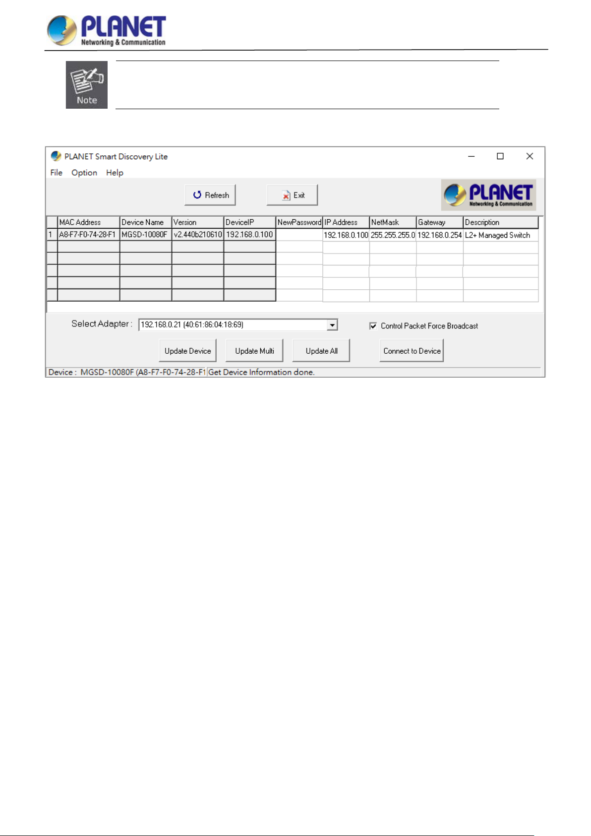
User’s Manual of MGSD-10080F
If there are two LAN cards or above in the same administrator PC, choose a different LAN card
by using the “Select Adapter” tool.
3. Press the “Refresh” button for the currently connected devices in the discovery list as the screen is shown as follows.
Figure 3-6: Planet Smart Discovery Utility Screen
1. This utility shows all the necessary information from the devices, such as MAC Address, Device Name, firmware version
and Device IP Subnet address. A new password, IP Subnet address and description can be assigned to the devices.
2. After setup is completed, press the “Update Device”, “Update Multi” or “Updat e All” but ton to take effect. The meanings
of the 3 buttons above are shown below:
Update Device: Use the current setting on one single device.
Update Multi: Use the current setting on choose multi-devices.
Update Al l: Use the current setting on whole devices in the list.
The same functions mentioned above also can be found in “Option” tools bar.
3. To click the “Control Packet Force Broadcast” function, it allows new setting value to be assigned to the Web Smart
Switch under a different IP subnet address.
4. Press the “Connect to Device” button and then the Web login screen appears in Figure 3-3.
5. Press the “Exit” button to shut down Planet Smart Discovery Utility.
45
Page 46

User’s Manual of MGSD-10080F
4. WEB CONFIGURATION
This section introduces the configuration and functions of the Web-based management.
About Web-based Management
The Managed Metro Switch offers manageme nt fe at ure s tha t allow users to manage the Managed Metro Switch from anyw here
on the network through a standard browser such as Microsoft Internet Explorer.
The Managed Metro Switch can be configured through an Ethernet connection, making sure the manager PC must be set on
the same IP subnet address as the Managed Metro Switch.
For example, the default IP address of the Managed Metro Switch is 192.168.0.100, then the manager PC should be set at
192.168.0.x (where x is a number between 1 and 254, except 100), and the default subnet mask is 255.255.255.0.
If you have changed the default IP address of the Managed Metr o Switch to 192.168.1.1 with subnet mask 255.255.255.0 via
console, then the manager PC should be set at 192.168.1.x (where x is a number between 2 and 254) to do the relative
configuration on manager PC.
Figure 4-1-1: Web Management
Logging on the Managed Metro Switch
1. Use Internet Explorer 8.0 or above Web browser. Enter the factory-default IP address to access the Web interface. The
factory-default IP Address as following:
https://192.168.0.100
2. When the following login screen appears, please enter the default username "admin" with password “admin” (or the
username/password you have changed via console) to login the main screen of Managed Metro Switch. T he logi n scr een
in Figure 4-1-2 appears.
46
Page 47

User’s Manual of MGSD-10080F
button. You need
Figure 4-1-2: Login Screen
Default User name: admin
Default Password: admin
After entering the username and password, the main screen appears as Figure 4-1-3.
Figure 4-1-3: Web Main Screen of Managed Metro Switch
Now, you can use the Web management interface to continue the switch management or manage the Managed Metro Switch
by Web interface. The Switch Menu on the left of the web page let you access all the commands and statistics the Managed
Metro Switch provides.
It is recommended to use Internet Explore 8.0 or above to access Managed Metro Switch.
The changed IP address takes effect immediately after clicking on the Apply
to use the new IP address to access the Web interface.
47
Page 48

User’s Manual of MGSD-10080F
For security reason, please change and memorize the new password after this first setup.
Only accept command in lowercase letter under web interface.
48
Page 49

User’s Manual of MGSD-10080F
4.1 Main Web page
The Managed Metr o Swit ch provides a Web-based browser interface for conf iguri ng and managi ng it. This interfac e allow s y ou
to access the Managed Metro S witch using the Web browser of your choice. This chapter describes how to use the Managed
Metro Switch’s Web browser interfa ce to confi gur e and man age it.
Sub Menu
Main Menu
Panel Display
Logout
Figure 4-1-4: Main page
Panel Display
The web agent displays an image of the Managed Metro Switch’s ports. The Mode can be set to display different information
for the ports, including Link up or Link down. Clicking on the image of a port opens the Port Statistics page.
The port states are illustrated as follows:
State Disabled Down Link
RJ45 Ports
SFP Ports
Main page
49
 Loading...