

Page 1

PLANET Mesh Network Manager Guide
802.11a/b/g Indoor Wireless Mesh Network
Access Point
MAP-3100 / MAP-3120
Mesh Network Manager (MnM)
Management Utility User Manual
PLANET Mesh Network Manager Guide
Page1 of 124
Page 2

PLANET Mesh Network Manager Guide
Copyright
Copyright © 2008 by PLANET Technology Corp. All rights reserved. No part of this publication may
be reproduced, transmitted, transcribed, stored in a retrieval system, or translated into any language
or computer language, in any form or by any means, electronic, mechanical, magnetic, optical,
chemical, manual or otherwise, without the prior written permission of PLANET.
PLANET makes no representations or warranties, either expressed or implied, with respect to the
contents hereof and specifically disclaims any warranties, merchantability or fitness for any particular
purpose. Any software described in this manual is sold or licensed "as is". Should the programs prove
defective following their purchase, the buyer (and not PLANET, its distributor, or its dealer) assumes
the entire cost of all necessary servicing, repair, and any incidental or consequential damages
resulting from any defect in the software. Further, PLANET reserves the right to revise this publication
and to make changes from time to time in the contents hereof without obligation to notify any person
of such revision or changes.
All brand and product names mentioned in this manual are trademarks and/or registered trademarks
of their respective holders.
Revision
Mesh Network Manager User’s Manual for PLANET Wireless Mesh Access Point
Model: MAP-3100 / MAP-3120
Rev: 2.0 (February, 2008)
Part No. EM-MAP3K_MnMv2.doc
PLANET Mesh Network Manager Guide
Page2 of 124
Page 3

PLANET Mesh Network Manager Guide
Table of Content
Table of Content 3
1 Overview 6
2 System Requirement 7
3 Utility Installation and Un-installation 8
3.1 Installation 8
3.1.1 Introduction 8
3.1.2 Choose Install Folder 9
3.1.3 Choose Shortcut Folder 9
3.1.4 Pre-Installation Summary 10
3.1.5 Installing 10
3.1.6 Installation Complete 11
3.2 Un-installation 11
3.2.1 Introduction 12
3.2.2 Uninstalling 12
3.2.3 Uninstallation Complete 13
4 How to Use PLANET Mesh Network Management Tools 14
4.1 Quick Start 14
4.2 Software Overview & Features 15
4.2.1 Software Layout 15
4.2.1.1 Map Container 15
4.2.1.2 MIB Reader 16
4.2.1.3 Alarm Viewer 17
4.2.2 Toolbar Reference 18
4.2.3 Features 20
4.2.3.1 Create Map 20
4.2.3.2 Open Map 21
4.2.3.3 Save Map 21
4.2.3.4 Topology Map 22
4.2.3.5 Set up New Scan 23
4.2.3.6 Map View 24
4.2.3.7 Status Pane 25
4.2.3.8 Scan IP Address 26
4.2.3.9 SNMP Community / Passwords (for Scan-IP) 26
4.2.3.10 Socket Port 28
4.2.3.11 SNMP Community / Passwords (for AP Unit) 28
4.2.3.12 Scan Interval 29
4.2.3.13 Import Background Image 30
4.2.3.14 Map Print 31
4.2.3.15 Map Zoom 32
4.2.3.16 Customize Map 33
4.2.3.17 Background Image Transparency 36
4.2.3.18 Block List 37
4.2.3.19 Lock / Unlock 38
4.2.3.20 Node details 39
PLANET Mesh Network Manager Guide
Page3 of 124
Page 4

PLANET Mesh Network Manager Guide
4.2.3.21 Client Properties 40
4.2.3.22 Get/Set using MIB Reader 41
4.2.3.23 Load/Unload MIB 44
4.2.3.24 Alarm Table 45
4.2.3.25 Add Trap Agent 46
4.2.3.26 View Log Files 48
4.2.3.27 Show Route 49
4.2.3.28 Create VPN Connection 51
4.2.3.29 Configure Mesh APs 56
4.2.3.30 Discovery Tool 58
4.2.3.31 View Interface and Client Live Statistic 58
4.2.3.32 Logout Client 60
5 Configure the Mesh AP using AP Configurator 62
5.1 Overview of AP Configurator 62
5.2 How to use AP Configurator 63
5.3 Configure the Mesh AP 65
5.3.1.1 System > System 65
5.3.1.2 System > Syslog 67
5.3.1.3 System > Advanced Tuning 67
5.3.1.4 Network > Network 70
5.3.1.5 Network > WAN 71
5.3.1.6 Network > VLAN 75
5.3.1.7 Network > Mesh 77
5.3.1.8 Network > Wireless Configuration 80
5.3.1.9 Network > Route 83
5.3.1.10 Network > IP Sec 84
5.3.1.11 Network > L2TP Client 86
5.3.1.12 Network > OLSR 87
5.3.1.13 Services > NTP 89
5.3.1.14 Services > DHCP 91
5.3.1.15 Services > MAC Access 93
5.3.1.16 Services > NAT 95
5.3.1.17 Services > Firewall 96
5.3.1.18 Services > Traffic Shaping 98
5.3.1.19 Services > PPTP Server 100
5.3.1.20 Services > Mobile IP (Future Feature) 102
5.3.1.21 Services > Captive Portal 103
5.3.1.22 Services > Radius 105
5.3.1.23 Services > Dynamic DNS 107
5.3.1.24 Services > Zero Config 108
5.3.1.25 Services > Auto IP 108
5.3.1.26 Services -> Route Watch Dog 109
5.3.1.27 Services -> System Watch Dog 110
5.3.1.28 Services -> SSHD 110
5.3.1.29 Services > WME 111
5.3.1.30 Management > HTTPD 113
5.3.1.31 Management > SNMPD 115
5.3.1.32 Management > SNMP Trap 117
5.3.1.33 Management > NMS Address 120
PLANET Mesh Network Manager Guide
Page4 of 124
Page 5

PLANET Mesh Network Manager Guide
5.3.1.34 Status > DHCP Client 121
5.3.1.35 Command > Reboot 121
5.3.1.36 Command > Reset 122
5.3.1.37 Command > Download/Upload 122
6 Technical Support 124
PLANET Mesh Network Manager Guide
Page5 of 124
Page 6

PLANET Mesh Network Manager Guide
1 Overview
This document provides a details information and application guidance for the user of the
management software, the PLANET Mesh Network Manager (MnM). This network
management system is intended to perform an overall monitoring and configuring features for
the PLANET Mesh Network.
PLANET Mesh Network Manager Guide
Page6 of 124
Page 7

PLANET Mesh Network Manager Guide
2 System Requirement
The PLANET Mesh Network Manager is written in JAVA, hence it has the feature of cross
platform, capable to run in most of the platform. The following are the recommended system
requirement.
- 256 MB RAM (recommended minimum)
- 10 MB hard disk space
- Microsoft Windows 2000, XP (recommended)
Besides, in order to enable the NMS to work properly, the following ports must be allowed
through any firewall between the NMS and the agent:
- Port 161 (by default) – Use for standard SNMP Get and Set
- Port 162 (by default) – Use for listen to SNMP Trap
- Port 4608 (by default) – Used by the Discovery Tool
- Port 8188 (by default) – Use to listen for the Layer-2 node’s notification
PLANET Mesh Network Manager Guide
Page7 of 124
Page 8
PLANET Mesh Network Manager Guide
3 Utility Installation and Un-installation
3.1 Installation
Insert the bundled CD into the CD-ROM drive to launch the auto run program. Once
completed, a menu screen will appear. Click the “PLANET Mesh Network Manager” hyperlink
and select “Open” or “Run” to initiate the install wizard.
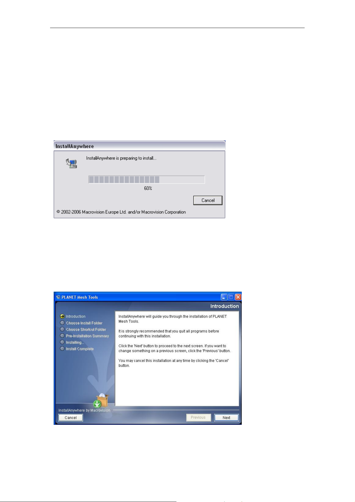
After the wizard completes preparation, follow the 6 easy steps directed by the wizard to
perform the installation.
3.1.1 Introduction
Simply explain what this software is about. Press Next to proceed.
PLANET Mesh Network Manager Guide
Page8 of 124
Page 9
PLANET Mesh Network Manager Guide
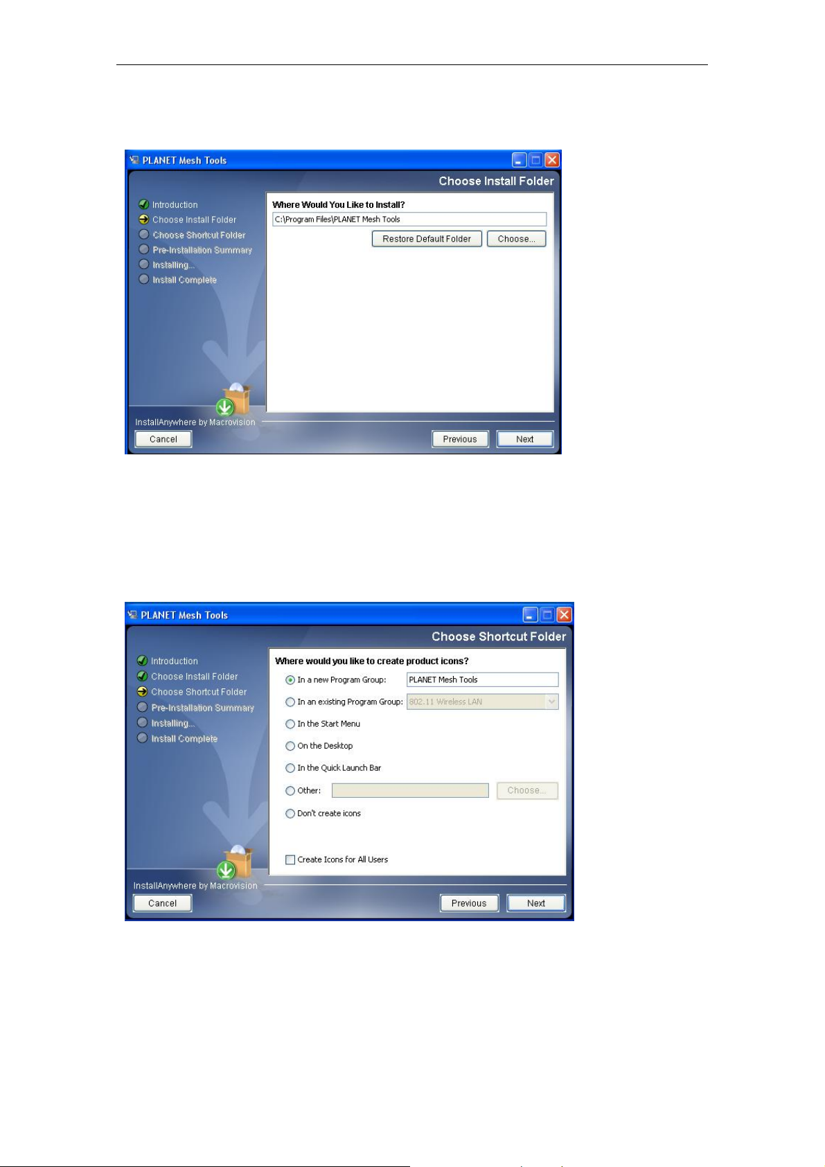
3.1.2 Choose Install Folder
Prompt user to choose the install path (directory) and name the install folder. Press Next to
proceed.
3.1.3 Choose Shortcut Folder
Specify where the software shortcut will be created at. Press Next to proceed.
PLANET Mesh Network Manager Guide
Page9 of 124
Page 10
PLANET Mesh Network Manager Guide
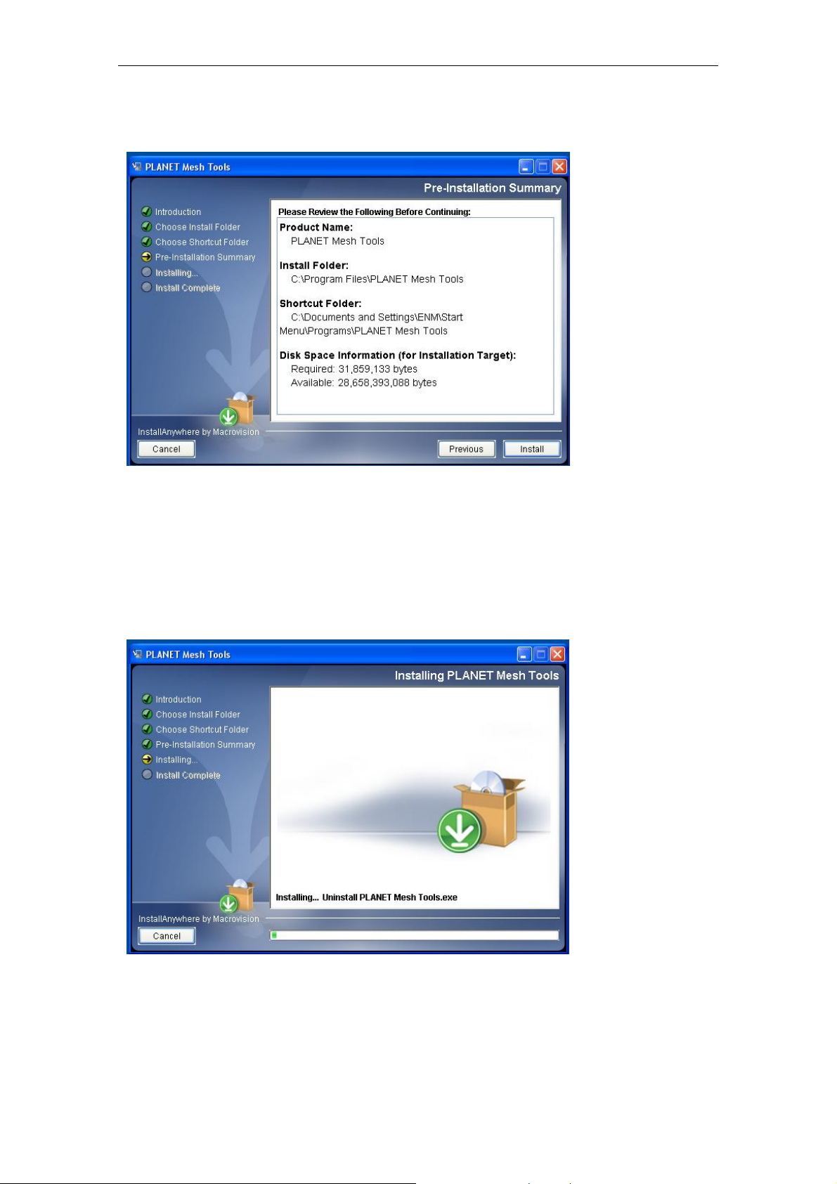
3.1.4 Pre-Installation Summary
Let user have a quick review about the installation settings before start installing. Press
Install button to start the installation.
3.1.5 Installing
Installation is in progress. Once the installation is completed it will direct the user to the next
step.
PLANET Mesh Network Manager Guide
Page10 of 124
Page 11
PLANET Mesh Network Manager Guide
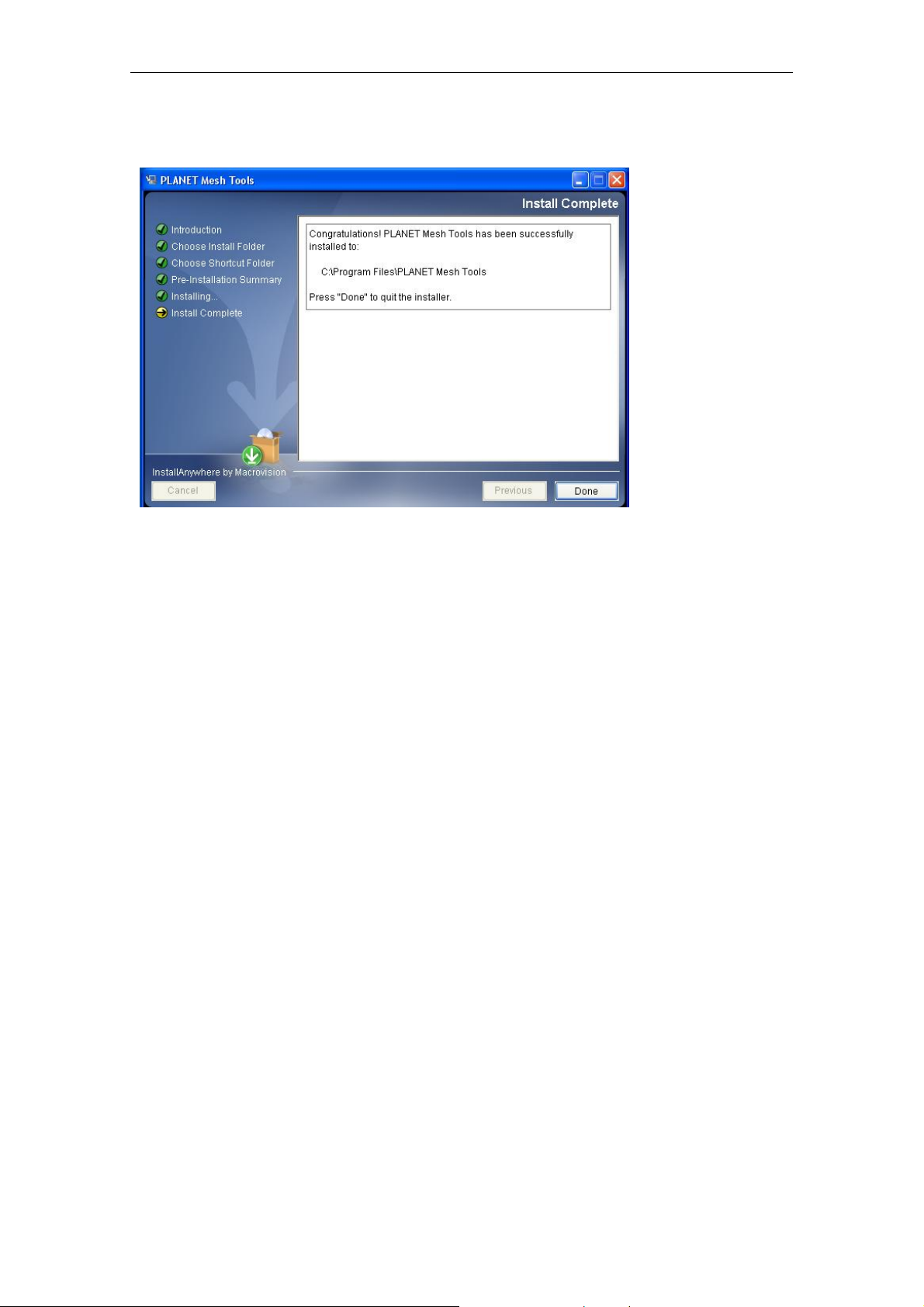
3.1.6 Installation Complete
Indicating the installation is completed, and user can select to restart the system instantly or
afterward, in order to complete the installation. Press Done to conclude the installation. After
that, you may launch the NMS through the shortcut you created previously.
3.2 Un-installation
In order to uninstall the PLANET Mesh Network Manager from your terminal, you can get the
uninstaller wizard from the software directory. The uninstaller, namely Uninstall PLANET
Mesh Tools, is located at the Uninstall_PLANET Mesh Tools folder. Launch the uninstaller
wizard by double-click the executable file. Follows the following steps:
PLANET Mesh Network Manager Guide
Page11 of 124
Page 12
PLANET Mesh Network Manager Guide
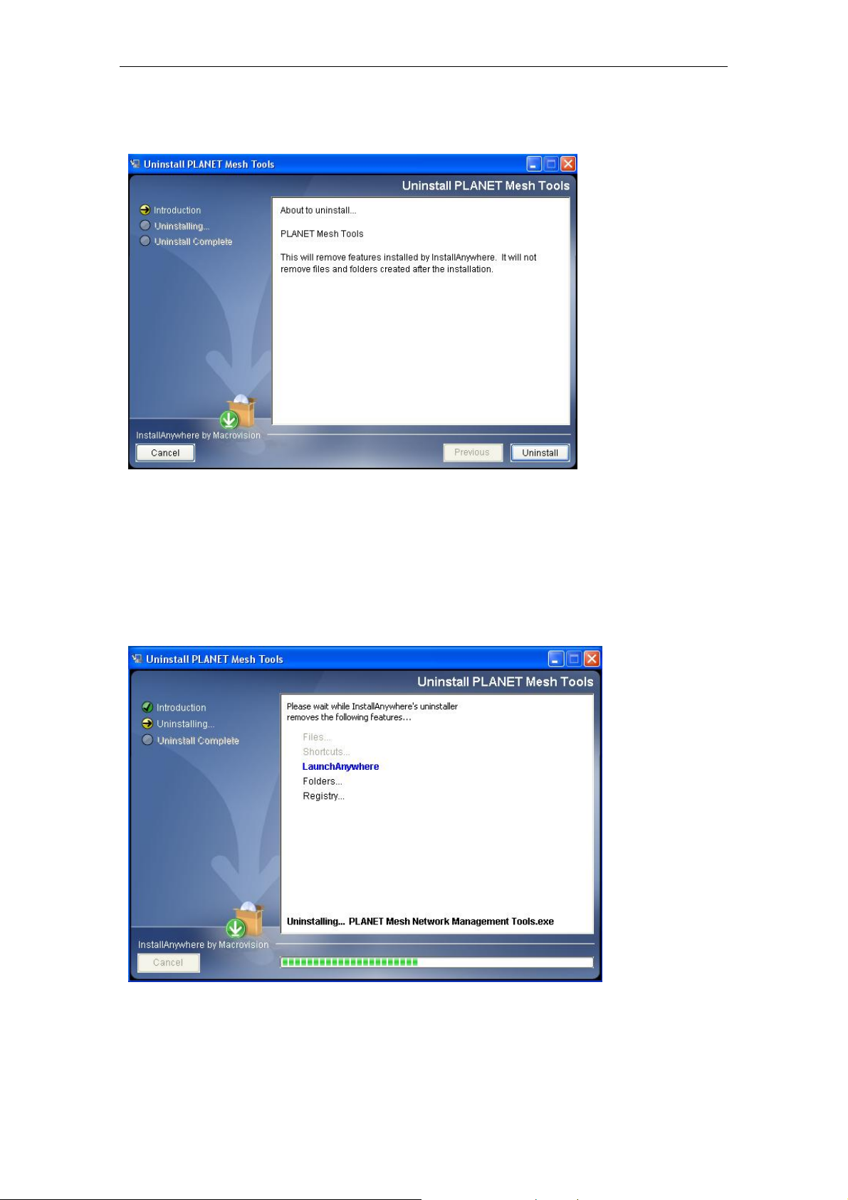
3.2.1 Introduction
An introduction regarding the uninstallation of the PLANET Mesh Management Tool. Click
Uninstall to start the process.
3.2.2 Uninstalling
Uninstallation is in the progress. Once the progress is completed, it will automatically direct
you to the next step.
PLANET Mesh Network Manager Guide
Page12 of 124
Page 13
PLANET Mesh Network Manager Guide
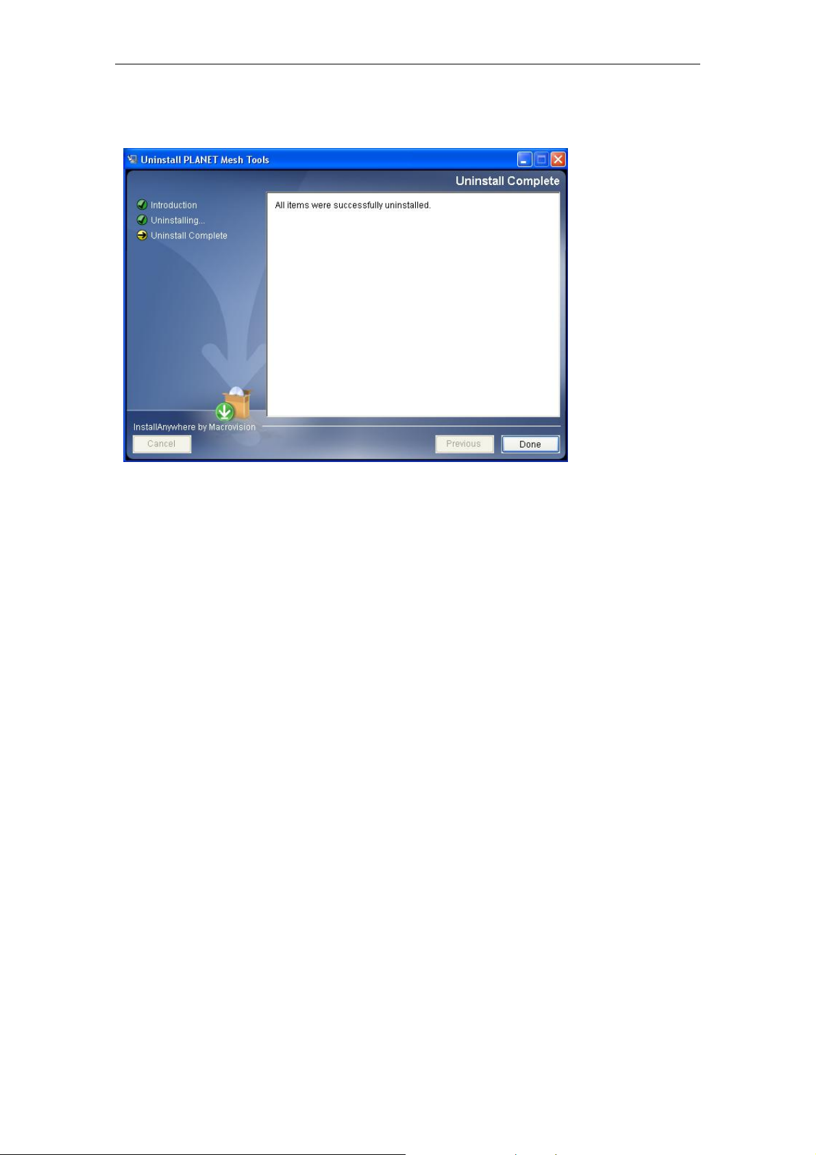
3.2.3 Uninstallation Complete
The software is uninstalled. You may choose to restart the terminal instantly or afterward in
order to complete the process.
PLANET Mesh Network Manager Guide
Page13 of 124
Page 14

PLANET Mesh Network Manager Guide
4 How to Use PLANET Mesh Network
Management Tools
4.1 Quick Start
First of all, make sure the terminal where you installed your PLANET Mesh Network
Management Tools is connected to the network, via Wireless or Wired LAN. Then, launch the
NMS at the location where you install it.
For a Layer 3 Mesh network:
Click the Create Map button on the toolbar to generate a new map profile. A dialog box would
appear, select SNMP Map and enter the name of the new profile. After that, hit the OK button
to complete the set up. A new map will be inserted into the NMS.
Then, click on the drop-down list on the toolbar of the new profile, where it prompts users to
insert the Scan IP Address, the destination IP Address to be scanned. Enter the desired IP
and click the button next to the list to save the IP. Finally, select the Start Scan button on the
map’s toolbar, the scan will be initiated and run. The result of the scan will be plotted on the
map area. User is free to adjust the position of the found-unit on the map.
For a Layer 2 Mesh network:
Prior to set up the utility, user is required to add the IP address of the NMS terminal on the
web page (Management > NMS Addresses) of Layer 2 nodes.
After the Layer 2 node configuration is done, activate the NMS and click the Create Map
button. A dialog box would appear, select Layer-2 Map and enter the name of the new profile.
After that, hit the OK button to complete the setup. A new map will be inserted into the NMS.
Before shutting down the NMS, user can save the profile settings, including the coordinate of
the found Mesh AP units on the map, by click on the Save Map button on the map toolbar.
The saved profile can be loaded directly to the NMS next time using the Open Map button on
the toolbar.
For further description regarding the functions and features of the PLANET Mesh Network
Management Tools, user may refer to the following section.
PLANET Mesh Network Manager Guide
Page14 of 124
Page 15
PLANET Mesh Network Manager Guide
4.2 Software Overview & Features
4.2.1 Software Layout
Before we proceed further, let us have an overview at the layout of the NMS. Basically, the
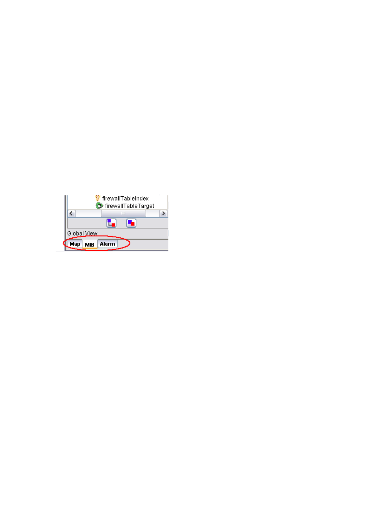
PLANET Mesh Network Management Tools is consist s of three ma jor sections:
Map Container
MIB Reader
Alarm Viewer
User can switch the view of the NMS by select the tabs at the left bottom corner, as illustrated,
or through the menu bar.
4.2.1.1 Map Container
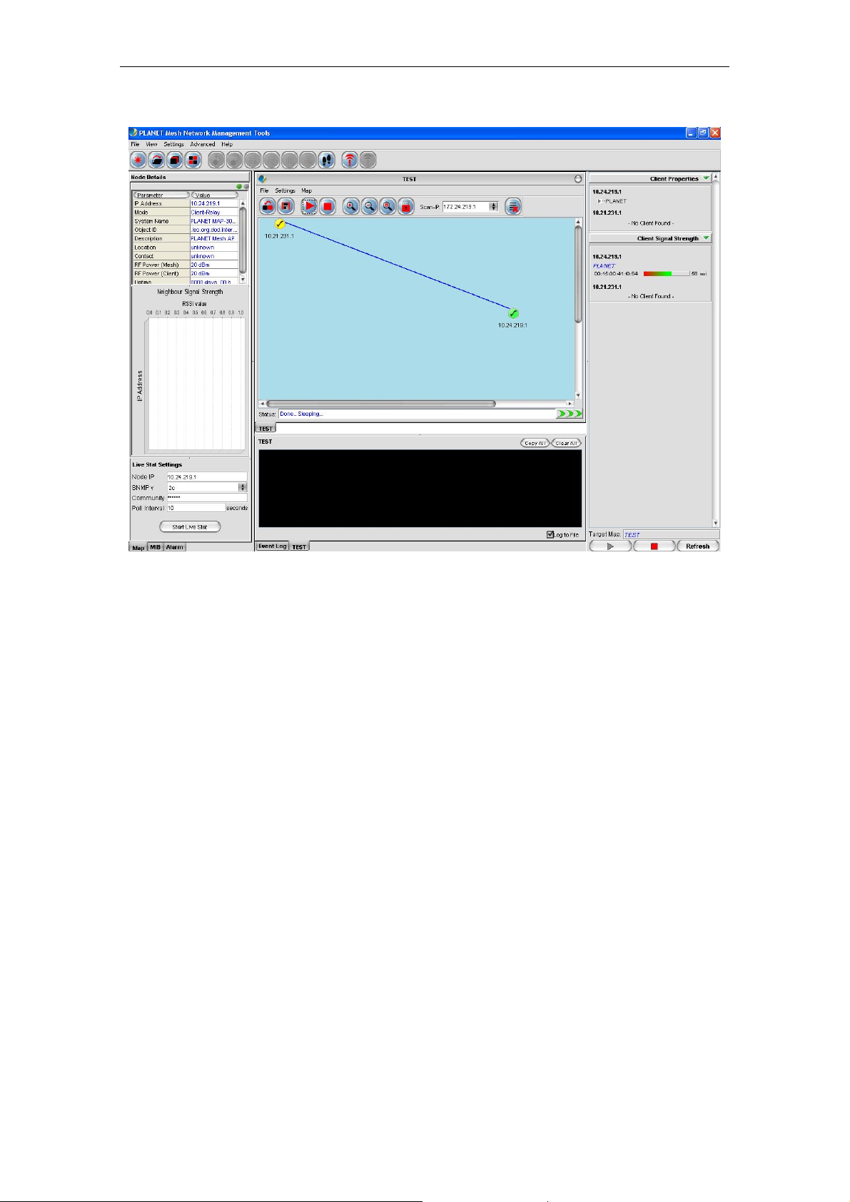
The Map Container is the section where user can monitor and manage the mesh network.
The network will be displayed in the form of graphical topology map, and the status will be
updated periodically.
The center frame of the Map Container is the space to plot the topology map. More than one
map can be created and run simultaneously. The status of the map will be logged to the
status pane at the bottom of the map. Each topology map has its own status pane.
The panel at the left of the map space is the Node Details panel. It is used to display the
properties of the selected Mesh AP unit on the topology map. The information of the AP will
be loaded into the table, and the graph below the table shows the signal strength between the
selected AP with its neighbour APs. The column at the bottom of this panel is used to invoke
the live stat monitoring feature.
The right panel, meanwhile, is to display the details of the clients associated to the Mesh AP
unit. The panel is divided into two parts, the Client Properties and Client Signal Strength
portion. Each portion will be automatically updated every minute, to provide the admin user
PLANET Mesh Network Manager Guide
Page15 of 124
Page 16
PLANET Mesh Network Manager Guide
the live result regarding the clients.
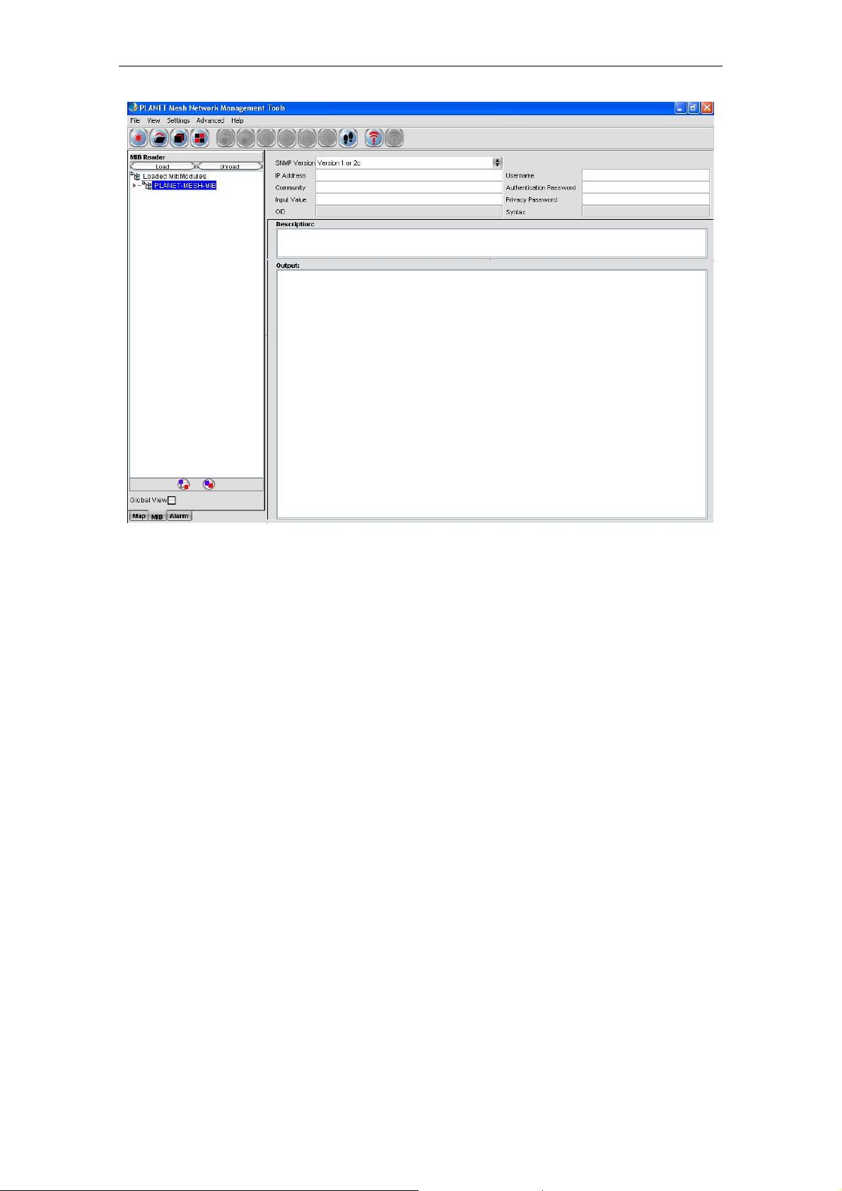
4.2.1.2 MIB Reader
The MIB Reader provides user a simple user-interface to retrieve as well as configure the
settings of the Mesh AP unit through the standard or vendor proprietary MIB files. With the
correct community and password, user can perform the SNMP actions such as SNMPGet,
SNMPSet and SNMPTable.
PLANET Mesh Network Manager Guide
Page16 of 124
Page 17
PLANET Mesh Network Manager Guide
The left pane displays the list of MIB and its tree. User can load and unload MIB file from the
desired location. More than one file can be loaded into the MIB Reader. In order to read or set
an item, expand the MIB tree, select the desired node. Select the SNMP version; fill in the IP
Address and other necessary keyword. Then click on the command button (SnmpGet,
SnmpSet, SnmpWalk, Load Table, etc..) on the toolbar. The output will be shown on the
Output column.
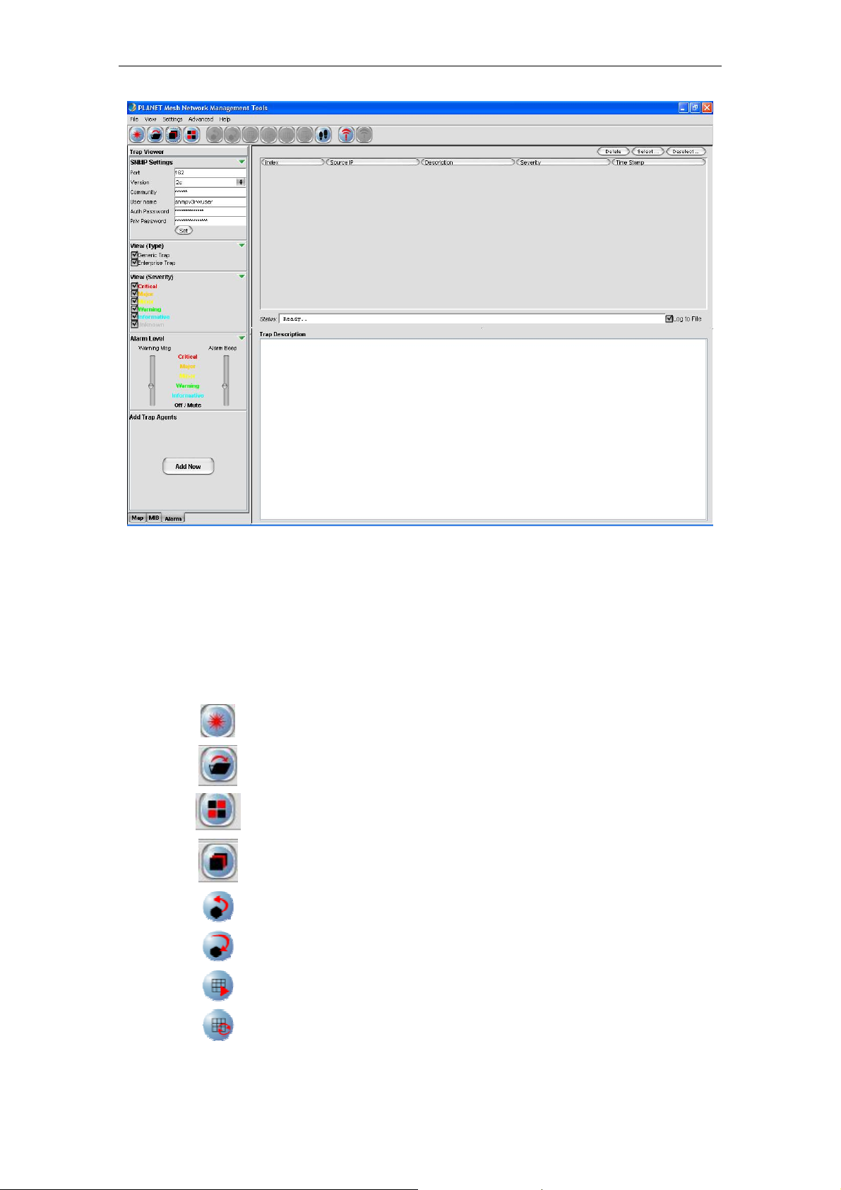
4.2.1.3 Alarm Viewer
The Alarm Viewer is a trap receiver. It received the SNMP alarms and notifications directed by
the Mesh AP units and display in the table at the center frame. Select the table entry in order
to view the description of the trap.
Note that the table is a read-only table, which displays the trap’s source IP Address,
description, severity and the time when the trap or alarm was caught. These alarms should be
deleted once they were reviewed and resolved, by clicking the Delete button.
PLANET Mesh Network Manager Guide
Page17 of 124
Page 18
PLANET Mesh Network Manager Guide
4.2.2 Toolbar Reference
This section provides a quick reference for the buttons in the toolbar of the NMS. The
description of the toolbar of the NMS is illustrated at the table below:
Button Name Function
Create Map
Open Map
View Tile
View Cascade
SnmpGet
SnmpSet
Load Table
Refresh Table
Create a new topology map profile
Open a pre-saved topology map profile
View the topology map in grid layout
View the topology map in cascade layout
SnmpGet the data from MIB tree
SnmpSet the data from MIB tree
Load the SNMP table from MIB tree
Refresh the SNMP table from MIB tree
PLANET Mesh Network Manager Guide
Page18 of 124
Page 19

PLANET Mesh Network Manager Guide
Add Table Row
Add a row to SNMP Table
Del Table Row
Delete a row from SNMP Table
SnmpWalk
Walk the selected item from the MIB tree
Start Trap
Initiate the Alarm Host system
Stop Trap
Stop the Alarm Host system
On the other hand, the following table shows the description of the toolbar of the map
container:
Button Name Function
Import
Background
Save Profile
Import an image file to use as the background
image of the topology map
Save the current topology map
Scan Start
Start the network scanning (SNMP Map only)
Scan Stop
Stop the network scanning (SNMP Map only)
Initiate Port
Close Port
Zoom In
Zoom Out
Zoom Fit
Lock
Unlock
Block List
Open port to listen to Layer-2 notification (Layer-2
Map only)
Close Layer-2 notification port (Layer-2 Map only)
Zoom in the topology map by 25%
Zoom out the topology map by 25%
Zoom the topology map to a size that fit the
screen
Lock the AP units on the map
Unlock the AP units on the map
Open the block list window
PLANET Mesh Network Manager Guide
Page19 of 124
Page 20
PLANET Mesh Network Manager Guide
4.2.3 Features
4.2.3.1 Create Map
In the NMS, two topology maps are available: SNMP Map and Layer-2 Map. These two types
of map look similar. The main difference between them is the method to get the topology
information.
• The SNMP Map is the ordinary type, where it uses the SNMP protocol to collect the
topology from the nodes discovered, and then plot the map using the collaborate data.
• Whereas the Layer-2 Map opens a specific port to listen for the notification from the
nodes, in order to plot the map. Prior to this, user is required to add the information
the NMS terminal (IP Address) to the node. Thus in fact, the Layer-2 Map can receive
the notification not only from the layer-2 mode AP, but any other mode as well, as
long as the NMS Address table is set.
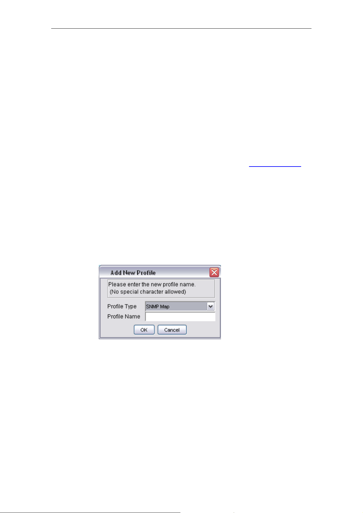
In order to create a new Topology map profile, user can click on the Create New button on
the main toolbar, or select File > Create New from the menu bar. A window would turn out to
prompt user for the type and name of the new map. User may select the type of the profile
from the drop down list, and enter the name in the provided column.
of
Please be aware that special character such as #, $, % (except _), are not allowed to use as
the name of the topology map name to avoid data corruption, since the name of the map will
be used as the header of their data file. On the other hand, the system also not allow user to
create a new profile with the name of the existing map in the NMS.
Two Profile Types can be found, SNMP Map and Layer 2 Map. Please chose SNMP Map for
Layer 3 mode Mesh Network Management and Layer 2 Map for Layer 2 Mode Mesh Network
Management.
Hit the OK button to proceed, or Cancel to close the window.
PLANET Mesh Network Manager Guide
Page20 of 124
Page 21
PLANET Mesh Network Manager Guide
Please make sure your Layer 2 Mesh Nodes are pre-configured for this MnM
installed PC. Otherwise, MnM can not display your Mesh nodes in the map also
Note
cannot show the correct information at the mean time. Please also refer to Web
guide section 3.5.10 for more.
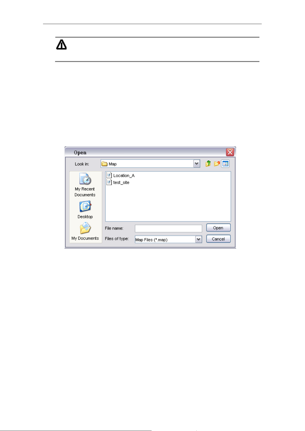
4.2.3.2 Open Map
In stead of create a brand new topology map, user can re-open the map profile that has been
saved previously. Click the Open Map button, or select File > Open Map from menu bar, a
file chooser window would appear on the screen, to prompt user to choose a map. Select the
desired one, and hit the Open button. The profile will be loaded to the NMS with all its
settings.
4.2.3.3 Save Map
As mentioned previously, the settings of the map profile can be saved to be loaded in the
future. Details of the map, for instance, the coordinate and SNMP passwords of the Mesh AP
units on the map, background image and block list, will be saved as a setting file.
In order to save a profile, select the Save Map button or File > Save Map from the map
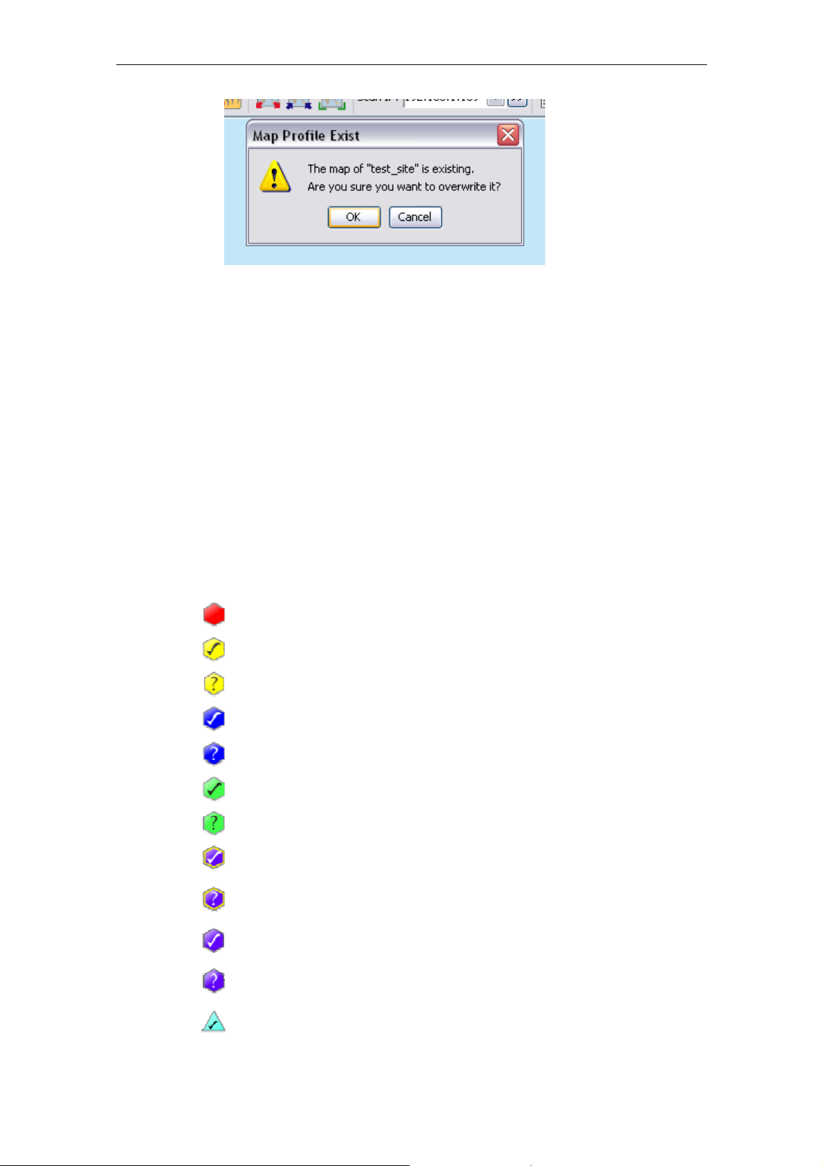
container toolbar of that particular map profile you wish to save. Note that if user is trying to
save a map profile that has a same name as one of the existing profile, a warning message
would appear to get confirmation from the user to overwrite the file. To proceed with the action,
click the OK button.
PLANET Mesh Network Manager Guide
Page21 of 124
Page 22
PLANET Mesh Network Manager Guide
By default, the profile will be saved to the Map folder in the program’s directory, with the name
of the map profile and extension .map or .l2map.
4.2.3.4 Topology Map
The topology map is actually the graphical representation of the actual Mesh network
topology which is being scanned. When a new scan is initiated, the result of the scan will be
processed by the NMS, and output to the map.
The AP unit would appear in different colors:-
Icon Indication
Inactive AP
Accessible gateway AP
Inaccessible gateway AP
Accessible relay AP
Inaccessible relay AP
Accessible client-relay AP
Inaccessible client-relay AP
Layer-2 gateway AP, which notified the NMS
Layer-2 gateway AP, which did not notify the NMS
(discovered as neighbour)
Layer-2 AP, which notified the NMS
Layer-2 AP, which did not notify the NMS (discovered as
neighbour)
AP Bridge
PLANET Mesh Network Manager Guide
Page22 of 124
Page 23
PLANET Mesh Network Manager Guide
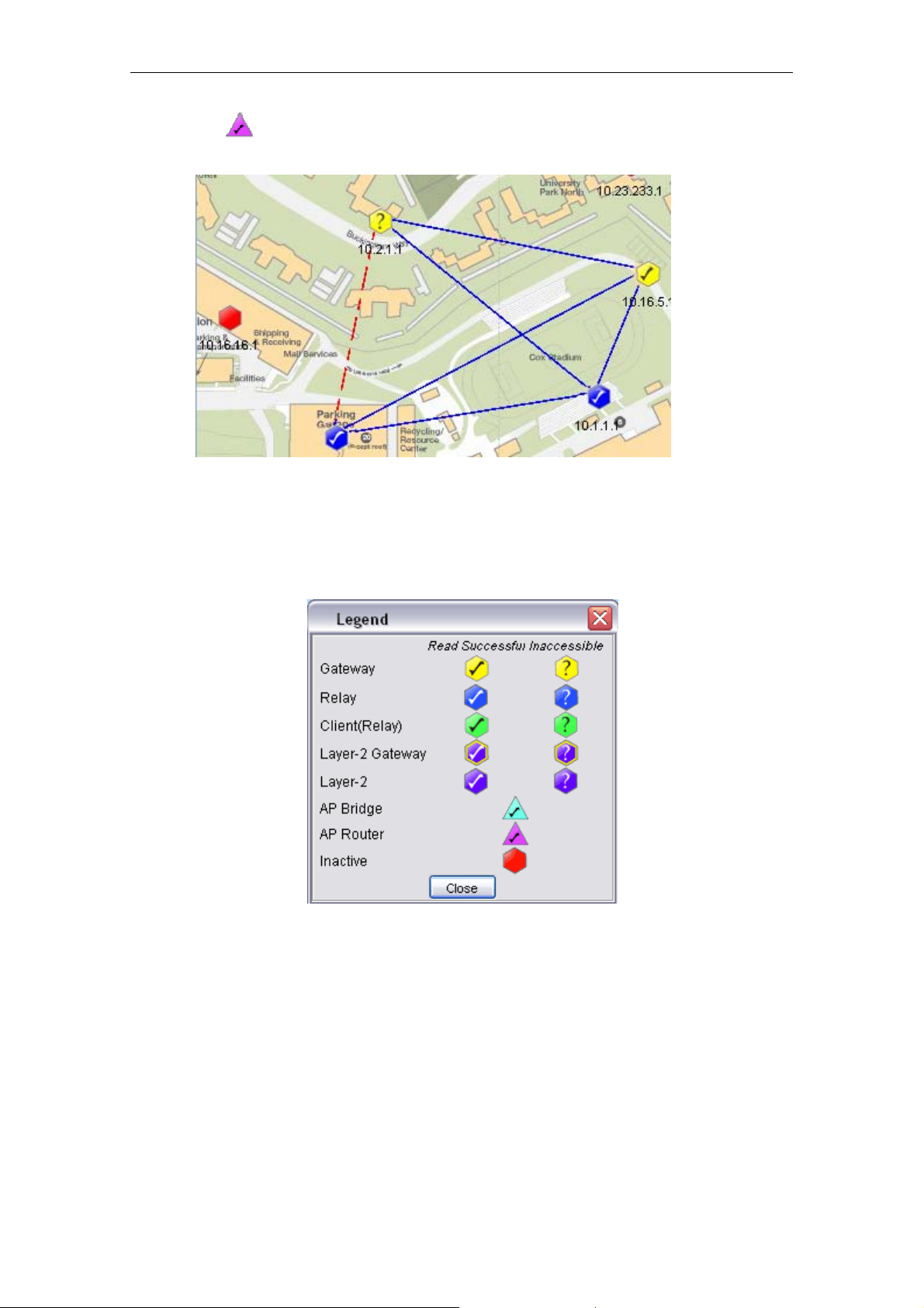
AP Router
The blue line in between the APs designates the solid link; whereas the red, dashed line
shows the indirect link. On the other hand, user may hit the Help > Legend option from the
menu bar to view the legend regarding the topology.
4.2.3.5 Set up New Scan
In order to set up a new scan for a SNMP topology map, click on the Start Scan button, or
select Map > Start Scan from the menu bar. Conversely, hit the Stop Scan button or select
Map > Stop Scan to halt the scanning process. The status of the map will be updated
periodically, hence whenever there is a change in the network, user might be able to monitor
via the NMS. The status bar at the bottom of the map displays the status of the scan.
On the other hand, in order to set up a new scan for the Layer-2 topology map, click on the
Initiate Port button, or select Map > Initiate Port from the menu bar. The map will receive the
PLANET Mesh Network Manager Guide
Page23 of 124
Page 24
PLANET Mesh Network Manager Guide
notification sent by the AP and plot the topology on the map. Conversely, hit the Close Port
button or select Map > Close Port from the menu bar to stop listen to the notification.
Every new found Mesh AP unit will be place on the right top angle on the map, with zero
coordinate. Then user is free to move the AP unit around the map. Once user completes the
positioning, save the map, and the system will remember the new coordinates in the future
scan.
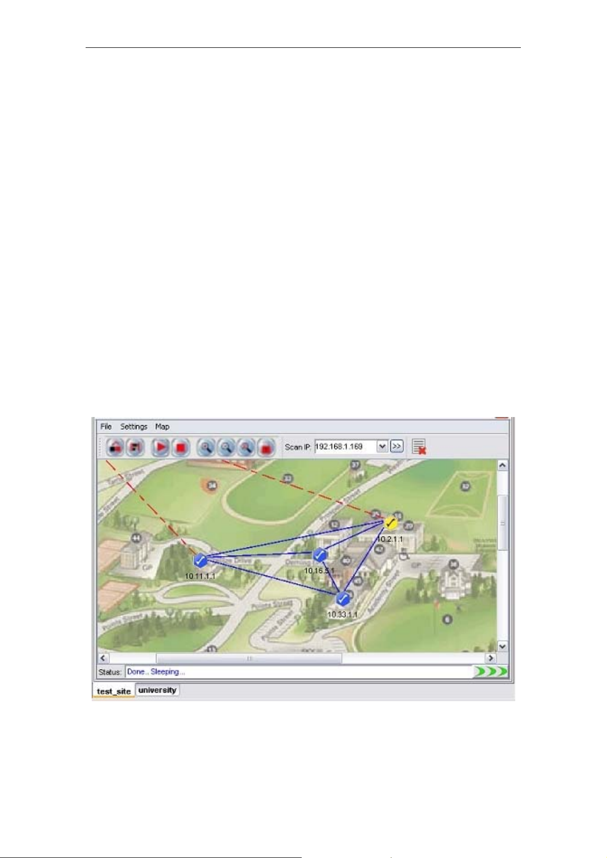
4.2.3.6 Map View
More than one topology map can be loaded to the NMS at the same time. By default, the
maps are viewed in cascade mode, where user needs to click on the tab at the bottom to
switch the map to view.
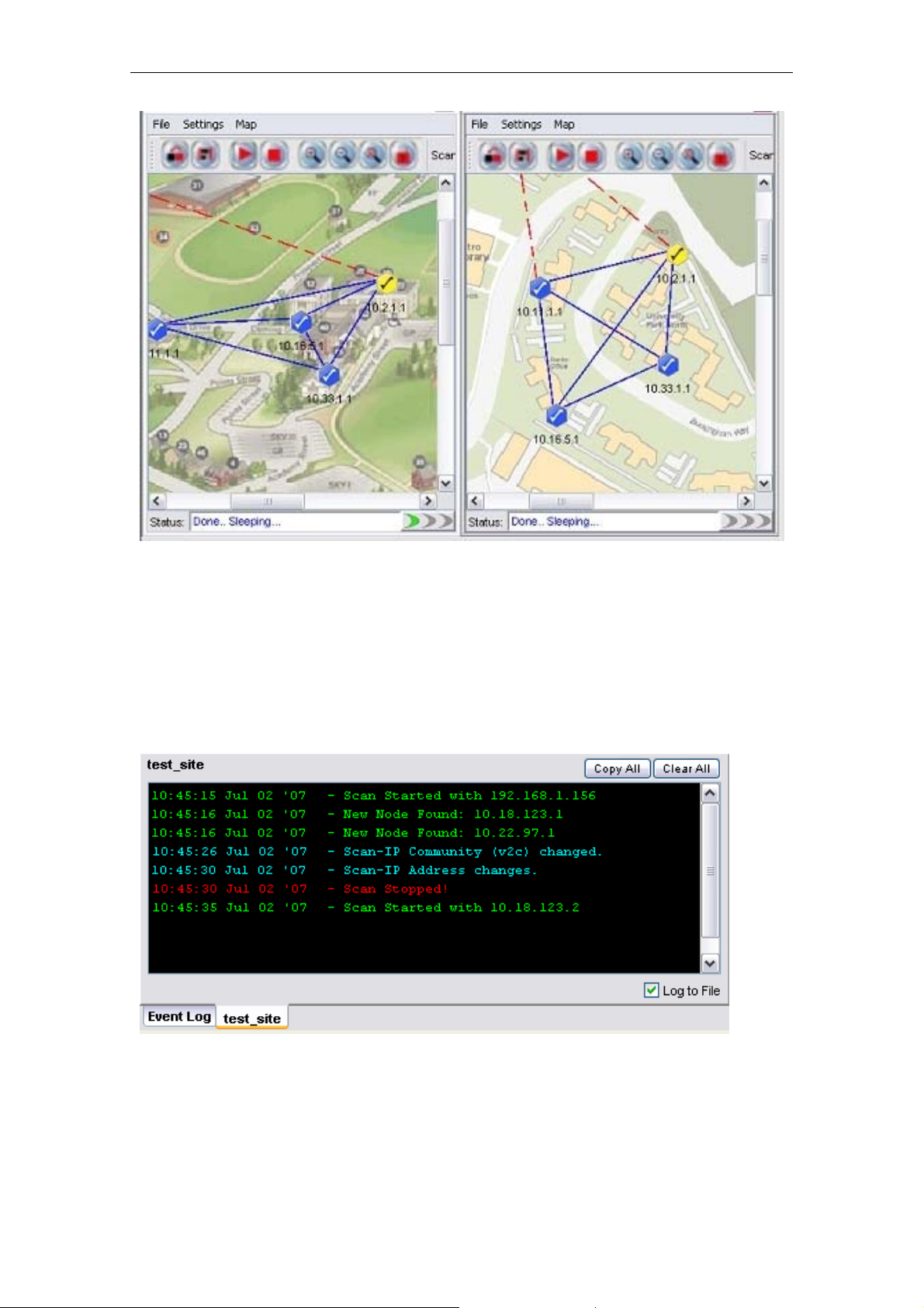
In order to change the view type, click the Tile button on the main toolbar, or select View >
Tile from the menu bar. The tile mode arranges the topology maps in a grid layout. To convert
the view mode to cascade, hit the Cascade button, or View > Cascade. The following figures
illustrate the difference between the two modes.
(Cascade mode)
PLANET Mesh Network Manager Guide
Page24 of 124
Page 25
PLANET Mesh Network Manager Guide
(Tile Mode)
4.2.3.7 Status Pane
The status pane is located at the bottom of the map container. It displays the nodes’ status
with the time and date; enable users to keep track of the changes in the topology.
The type of message can be varied by the color of the text. Green text indicating positive
message such as scan started or nodes found; red text shows the negative message such as
nodes down or timeout; whereas cyan text displaying system message, for instance, system
settings changed.
The Copy All and Clear All buttons on the top of the pane performs the copy and delete text
PLANET Mesh Network Manager Guide
Page25 of 124
Page 26
PLANET Mesh Network Manager Guide
action in the status pane. Tick the checkbox at the bottom to log the status message to the
alarm log file, which will be saved to the folder Alarm_Log at the install directory.
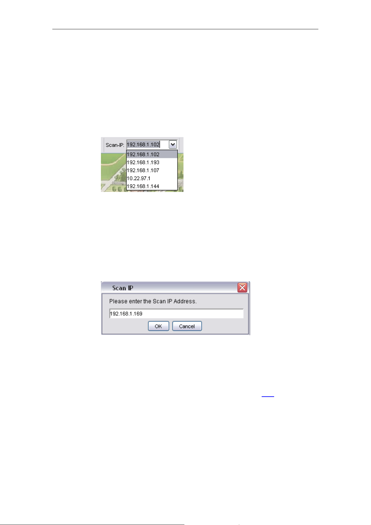
4.2.3.8 Scan IP Address
The Scan IP Address is the IP Address that the scanning process uses when initiate a scan
for a SNMP Map.
User might enter the IP Address at the drop down list, or choose from the list. In order to
apply the new Scan IP, user is required to restart the network scanning. (A running scan will
be stopped when a new IP Address is selected.)
n the other hand, the Scan IP can also be set by selecting Settings > Scan IP from the map
O
container’s toolbar. A window would appear to prompt user for the new IP Address. Hit the OK
button to apply the change.
4.2.3.9 SNMP Community / Passwords (for Scan-IP)
The PLANET Mesh Network Management Tools use the SNMP method to read the topology
of the network. There are two types of SNMP key used for the topology scan, which are the
Scan-IP key and the AP Unit key. More details about the latter please click here
.
Commonly, the use of SNMP varies by its version. If a user select version 2c, the SNMP key
to use is a community; on the other hand, if version 3 is used, the SNMP key will be a
SNMPv3 username, with its corresponding authentication password and privacy pass phrase.
As you can see throughout this document, every feature that implements SNMP will have
both options (use version 2c or 3).
PLANET Mesh Network Manager Guide
Page26 of 124
Page 27
PLANET Mesh Network Manager Guide
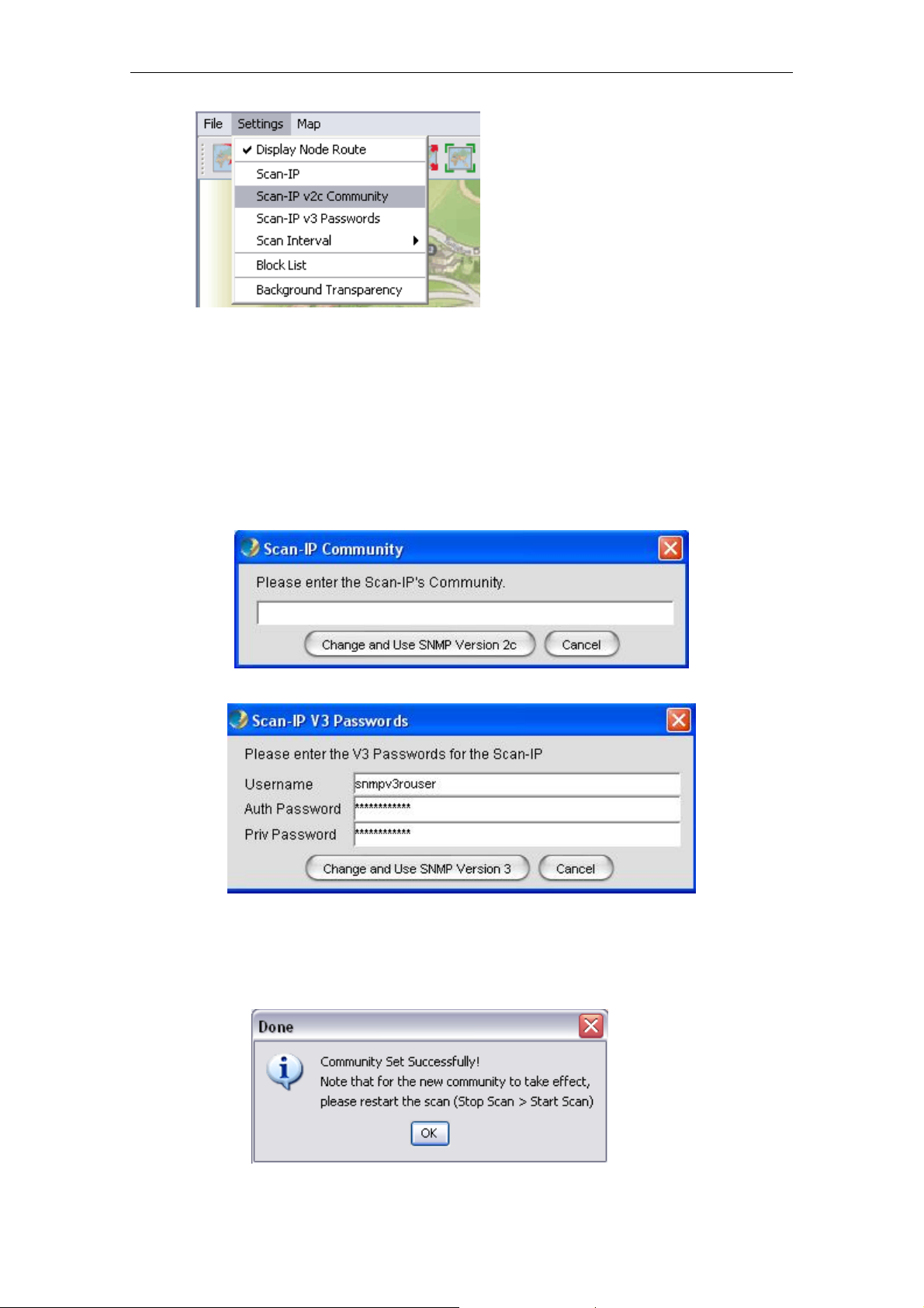
Basically, the Scan-IP key is the SNMP key that used for the Scan-IP which initiates the scan.
In order to configure the community of the Scan-IP, select Settings > Scan-IP v2c
Community from the map container menu. On the other hand, select Settings > Scan-IP v3
Passwords to change the SNMP version 3 Passwords. A window would turn up to prompt
user for the new key(s).
Press Change and Use SNMP Version X button to proceed. If the change is ssfully,
succe
the following dialog box would appear, to remind user to reset the scan in order to let the new
community or passwords to take effect.
PLANET Mesh Network Manager Guide
Page27 of 124
Page 28
PLANET Mesh Network Manager Guide
The default value for Scan-IP:
Community: public
Username: snmpv3rouser
Password: snmpv3password
Passphrase: snmpv3passphrase
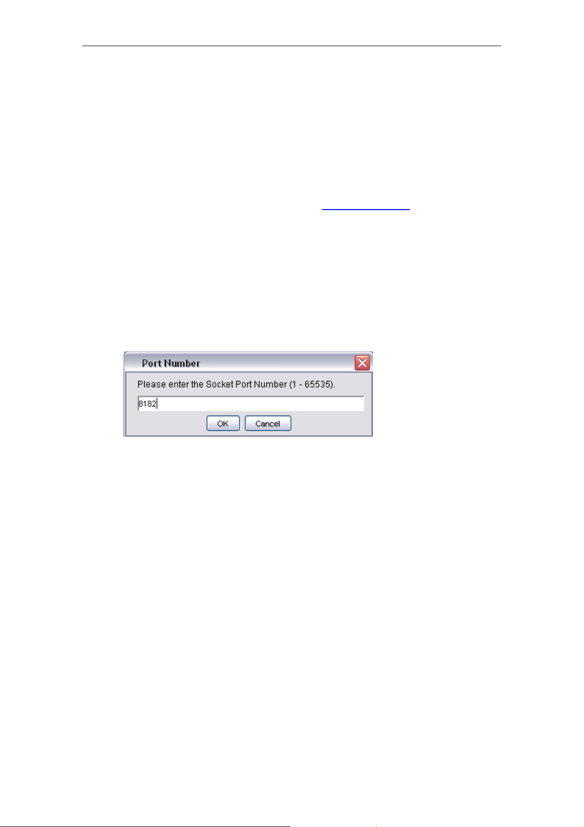
4.2.3.10 Socket Port
The notification of an AP node is sent according to its NMS Address Table
the IP Address and port number of the destination (NMS). For instance, if the admin has
added a table entry with port number 8000 at the AP, the NMS user can change the sock
port number to 8000 in order to receive the notification.
order to update the socket port, select Settings > Socket Port from the menu bar. A dialog
In
box would appear on the screen to prompt for the port number, which range from 1 to 65535.
Hit OK to confirm the change.
. The table defines
et
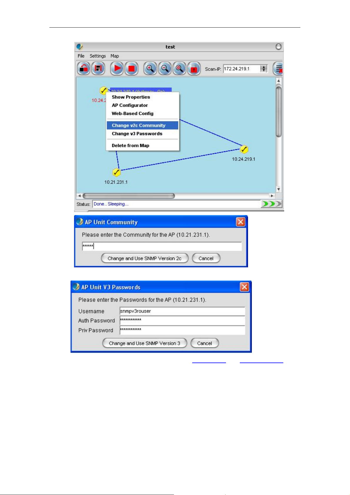
4.2.3.11 SNMP Community / Passwords (for AP Unit)
In case if a Mesh AP utilizes a different community or passwords from the others, the NMS
might fail to read the topology from it. Hence, user might need to edit the individual AP unit
SNMP keys, by right-click the desired active node. Select Change v2c Community from the
popup menu to change the community; or click Change v3 Passwords to change the v3
keys; enter the correct value in the dialog box and click Change and Use SNMP Version X.
PLANET Mesh Network Manager Guide
Page28 of 124
Page 29
PLANET Mesh Network Manager Guide
Note that the AP Unit Keys is also used for read the Node Details
and Client Properties. The
default SNMP version and keys of the Mesh AP is inherited from the Scan-IP that found them.
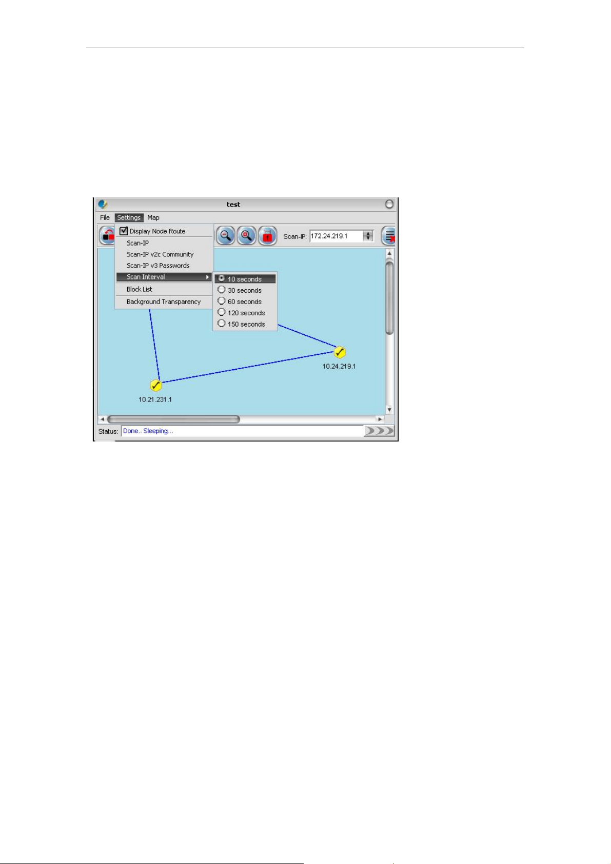
4.2.3.12 Scan Interval
The scan interval defines the time interval between every round of scanning. By default, the
NMS will sleep for 10 seconds once a network scan is completed. User may change the time
interval by select Settings > Scan Interval, and choose the desired time interval. The
available options:
PLANET Mesh Network Manager Guide
Page29 of 124
Page 30
PLANET Mesh Network Manager Guide
10 seconds
30 seconds
60 seconds
120 seconds
150 seconds
The changes will take effect immediately.
4.2.3.13 Import Background Image
User can change the background of the topology map by import any desired image file from
other resource. Click on the Import Background Image button, or select File > Import
Background from the map container’s menu bar. A file chooser window would appear, to
prompt user for the image file that wished to import.
PLANET Mesh Network Manager Guide
Page30 of 124
Page 31

PLANET Mesh Network Manager Guide
After select a image file (.jpg, .gif, .png ..etc), click the Open
loaded into the topology map.
4.2.3.14 Map Print
button. The new image will be
The NMS also provide the printing feature, where user is able to print the whole map by just
select the File > Print Map option from the Map Container menu bar. Then it will redirect the
map to the printer connected to the terminal where you run the NMS.
PLANET Mesh Network Manager Guide
Page31 of 124
Page 32

PLANET Mesh Network Manager Guide
4.2.3.15 Map Zoom
As a graphical solution for a network system, the PLANET Mesh Network Management Tools
provides the zooming feature for the user to manage the topology map more efficiency. Three
options are available: Zoom In, Zoom out and Zoom Fit.
The Zoom In and Zoom Out feature enable user to enlarge and minimize, respectively, at the
scale of 25%. Whereas the Zoom Fit feature will resize the topology map to the most suitable
size to fit in the screen. The following figures illustrate the effect of the zoom features.
(Original size)
(Zoom In)
PLANET Mesh Network Manager Guide
Page32 of 124
Page 33

PLANET Mesh Network Manager Guide
(Zoom Out)
(Zoom Fit)
4.2.3.16 Customize Map
This feature provides user the flexibility to change the look and feel of the topology map, by
replacing the existing AP unit image and the link between APs. User can import their custommade icon, or adjust the color to fit their visual requirement.
The method is straight forward. Select Settings > Customized Map from the NMS menu bar,
to invoke the Map Customization Tool window, as illustrated.
PLANET Mesh Network Manager Guide
Page33 of 124
Page 34

PLANET Mesh Network Manager Guide
PLANET Mesh Network Manager Guide
Page34 of 124
Page 35

PLANET Mesh Network Manager Guide
As you can see from the figures, the customization can be divided to two parts, the Node and
the Link. At the Node part, user may select the icon that need to be updated, and then fill in
the path of the new image (or click the “…” button to choose from the file chooser window).
Hit the Update button to update the new image icon. Besides, user can also decide whether
to show the indication of the AP-unit, which is the IP Address, by using the available
checkbox; and alter the foreground color of the IP Address using the “…” button to select a
desired color from the popup window. Hit the Save & Apply Changes button to commit the
changes. The Use Default button enables the user to restore the default settings of the AP
unit look and feel.
Meanwhile, in order to change the style of the link, switch the Map Customization Tool to the
Link page. User can change the color by hitting the “…” button to select a desired color from
the popup window. Then key in the thickness of the link and its dashing pattern. The dashing
pattern defines the way the dashed link look like. The following table explains how to use the
dashing pattern. After fill in the data, user may click the Update button to update the image at
the preview. Once confirm the changes, select the Save & Apply Changes button to commit
the change.
Pattern
Preview
(line1, space1, line2,
space2)
20, 0, 0, 0
20, 10, 20, 10
5, 10, 5, 10
20, 3, 10, 3
20, 10, 30, 5
Here is an example to show the effect of the map customization.
a) The original map
b) Select Map Customization Tool and change the gateway & relay icon
PLANET Mesh Network Manager Guide
Page35 of 124
Page 36

PLANET Mesh Network Manager Guide
c) Switch to Link page and edit the attributes
d) The customized map will look like this now.
Note that, the changes of the AP unit node and link applies to every map created or opened
on the NMS.
4.2.3.17 Background Image Transparency
This is a special tool used to adjust the opacity of the background image of the topology map.
Select Settings > Background Transparency from the map container menu bar to allow
users to alter the transparency of the background to a level that the APs and links are clear to
view.
View the following figures to see the effect of the transparency tool.
PLANET Mesh Network Manager Guide
Page36 of 124
Page 37

PLANET Mesh Network Manager Guide
(100%)
(50%)
(10%)
The tool will be closed automatically when it loses focus (mouse click anywhere out from the
tool).
4.2.3.18 Block List
The Block List offers the NMS users a filtering tool in the topology map. User can define the
IP Address to block, once the AP is blocked, it will be removed from the topology map, and
will not be added to the map even if it is detected by the NMS.
To move an IP to the block list, click the Block List button on the toolbar, or select Settings >
Block List from the menu bar. A window will emerge, as shown by the figure above. Then
user can choose the node to block from the Available Nodes column. Select the IP, and hit the
PLANET Mesh Network Manager Guide
Page37 of 124
Page 38

PLANET Mesh Network Manager Guide
Add button. The IP will be move over to the Nodes to Block column. On the other hand, if
user wishes to undo the step, use the Remove button to move the IP back to the available list.
The Add All and Remove All button perform the same operation by moving every IPs in the
list. Finally, hit the OK button to commit the change. (Note: asterisk in the list shows the IP is
a gateway node).
The blocked IP Address will be saved into the map setting file when the user saves the
topology map. Hence the IP will still be blocked when the current map profile reload in the
future.
4.2.3.19 Lock / Unlock
This feature is intended to prevent the user from dragging the node away from its current
position accidentally. User can select Map > Lock AP from the menu bar or use the Lock
AP button on the toolbar to lock up the nodes on the map.
PLANET Mesh Network Manager Guide
Page38 of 124
Page 39

PLANET Mesh Network Manager Guide
Conversely, click the Map > Unlock AP or Unlock AP button on the toolbar to release the
lock. Hence, once user has complete positions the nodes, turn on the lock.
4.2.3.20 Node details
The table next to the map container is the node details table. The table displays the properties
of the selected Mesh AP unit. In order to load the data, user can double-click on an active unit
(gateway or relay or client-relay), or right click then choose the Show Properties item from
the popup menu.
PLANET Mesh Network Manager Guide
Page39 of 124
Page 40

PLANET Mesh Network Manager Guide
As mentioned previously, the NMS use the SNMP method to read the data. Hence if the data
is failed to load, you may check the SNMP Community or Passwords. The two small circles
on the top of the table indicate the status of the table. If the green circle is light up, it shows
the table is loaded completely; if the orange circle is light up, it means the table is loading the
data, else if the circle to turn to red color, it indicates that the data loading is failed.
On the other hand, the bar chart at the bottom of the table displaying the signal strength (in
RSSI) between the selected AP and all its neighbour nodes. The scale of the chart can be
enlarged by dragging the desired range of x-axis. Drag backward to reset the chart.
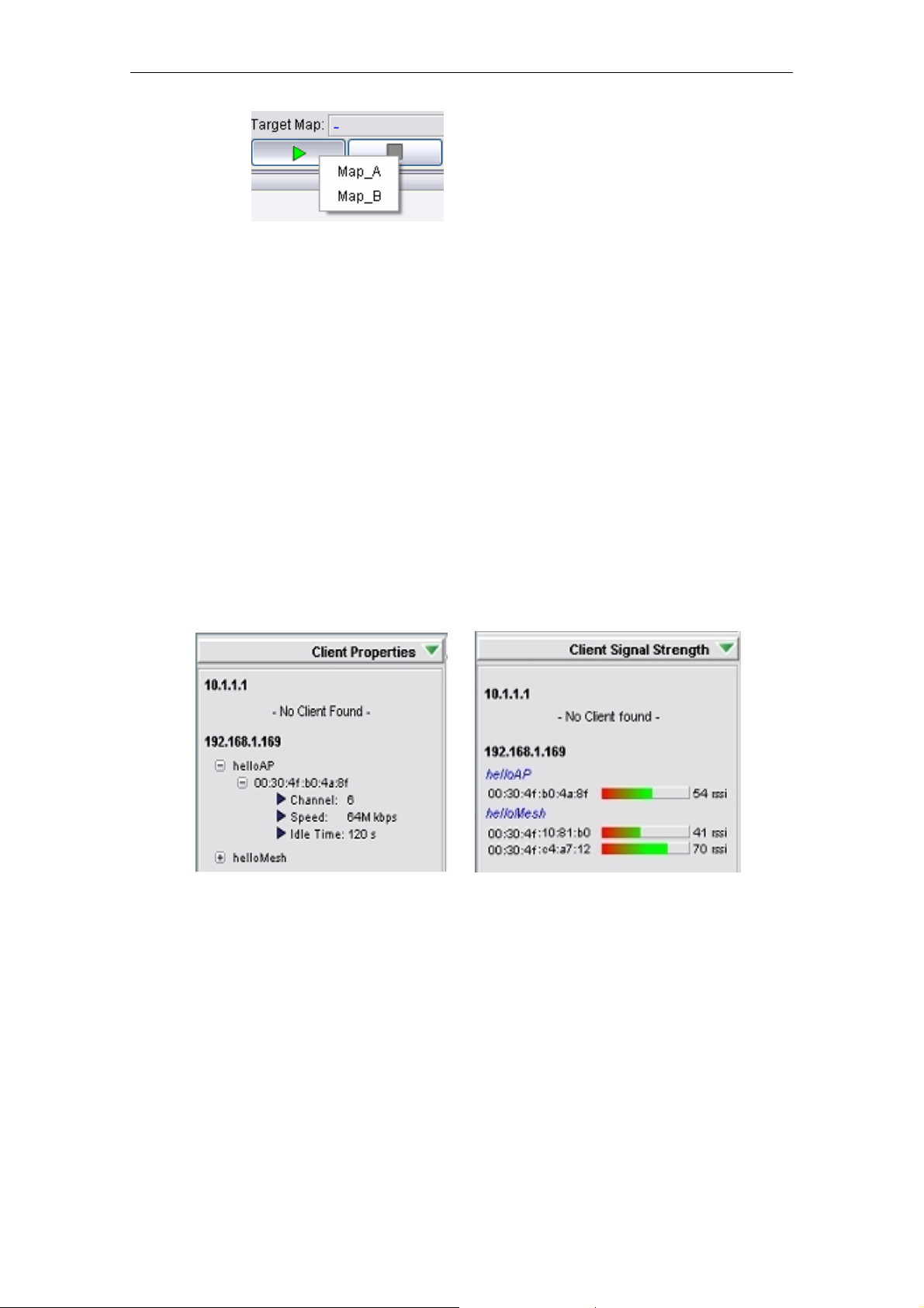
4.2.3.21 Client Properties
The client properties panel is located at the other side of the map container. In order to initiate
the NMS to download the client details, hit on the Start button at the bottom of the panel. In
case if there is more than one map is running, a menu would popup to prompt user to select
which map to be targeted. Once selected, the scanning will be started instantly.
PLANET Mesh Network Manager Guide
Page40 of 124
Page 41
PLANET Mesh Network Manager Guide
The automatic refresh feature of the client properties panel enable the admin uses the live
information regarding the clients associated to the Mesh AP unit discovered by the NMS. The
panel will be refreshed once per minute. On the other hand, if user wishes to refresh the
panel manually, simply click the Refresh button at the bottom of the panel. While the
downloading is in progress, the buttons will be replaced by a progress bar, showing the status
of the process. The NMS will download the information from every single node in the target
map discovered. To stop the scan, simply hit on the Stop button. The Target Map column
displays the name of the map where the client panel is scanning.
The panel is divided into two portions, the Client Properties and Client Signal Strength. The
Client Properties portion display the details regarding the client, for inst ance the MAC Address,
channel number, link speed and the idle time. In the case if there is no client associated to
the AP, a message “No Client Found” will be displayed instead.
On the other hand, the Client Signal Strength panel displays the signal strength of the clients
associated to the AP, in the unit of rssi. Similarly, if there is no client associated to the AP, a
message “No Client Found” will be shown.
4.2.3.22 Get/Set using MIB Reader
This section describes briefly about the usage of the MIB Reader of the PLANET Mesh
Network Management Tools.
PLANET Mesh Network Manager Guide
Page41 of 124
Page 42

PLANET Mesh Network Manager Guide
As illustrated, the center frame of the MIB Reader consists of three parts, SNMP keywords,
description area and output area. The SNMP keywords portion is the area where user fills in
the necessary parameter that need to perform any SNMP action. For instance, if the SNMP
version to use is version 1 or 2c, then the Community is the required field; else if version 3 is
selected, then user need to fill in the username, authentication password, and privacy
password fields. The Input Value field is used when user wish to execute the SNMP Set
command.
The Description area displays the description of the selected MIB tree node; whereas the
Output area prints out the output of the SNMP action.
• Get Action
PLANET Mesh Network Manager Guide
Page42 of 124
Page 43

PLANET Mesh Network Manager Guide
1. Select any tree node (make sure it is either read-only or read-write type)
2. Fill in the required parameter according to the version of SNMP to use.
3. Click the SnmpGet button on the toolbar.
4. The output should now display at the Output area.
• Set Action
1. Select any tree node (only read-write type)
2. Fill in the required parameter according to the version of SNMP to use.
3. Enter the value to be set at the Input Value column. You may refer the Syntax
column to ensure the type of the input (eg: Integer, DisplayString..).
4. Click the SnmpSet button on the toolbar .
5. The Output area will display the result of the action, either “(Set
Successfully…)” or “(Set Failed…)”.
• Read Table Action
1. Select a table tree node
2. Fill in the required parameter according to the version of SNMP to use.
3. Click the Load Table button on the toolbar.
4. The Output field should display the whole table now.
5. Use the Refresh Table to reload the table.
• Add Table Row Action
1. Repeat the first three steps of Read Table Action
2. Then enter the table values in the Input Value field. Values are separated by
a comma (,). (see the following figure)
3. Click the Add Table Row button on the toolbar.
4. The new entry should be added to the table.
• Delete Tabl e Row Action
1. Repeat the first three steps of Read Table Action
2. Select the entry that you wish to remove from the table.
3. Click the Delete Row button on the toolbar.
4. A popup window would appear to ask for your confirmation to delete the
selected entry. Hit OK to proceed.
5. The selected entry should be removed from the table.
• Snmp Walk Action
1. Select any tree node. (It can be a table, scalar or even the main node)
2. Fill in the required parameter according to the version of SNMP to use.
PLANET Mesh Network Manager Guide
Page43 of 124
Page 44
PLANET Mesh Network Manager Guide
3. Click the SnmpWalk button on the toolbar.
4. The output should now display at the Output area. It could take some time to
fetch all the data if the selected data is large.
Note: Please try to avoid Add or Delete the SNMP Table entry of the customized-MIB, since
there are some tables which are internally correlated, such as VLAN table and Wireless table.
Setting the table incorrectly would cause severe corruption in the system.
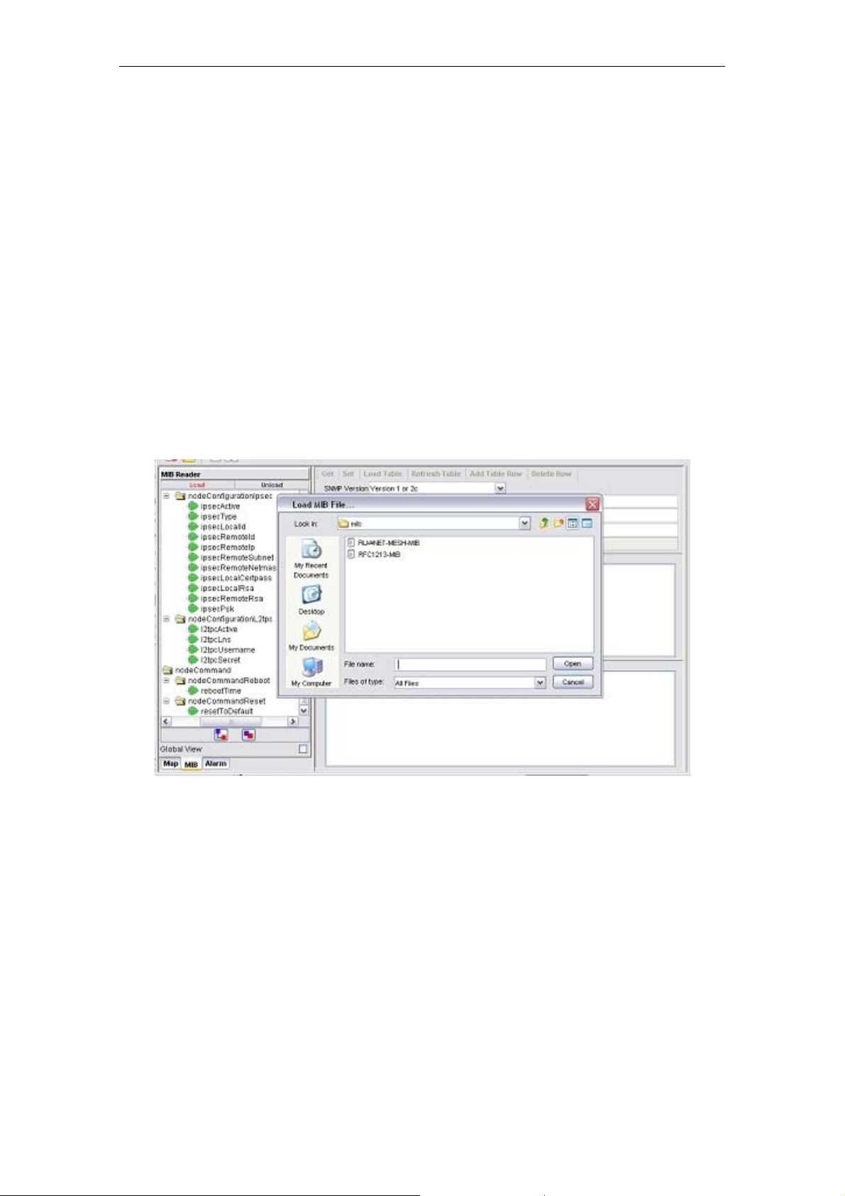
4.2.3.23 Load/Unload MIB
The MIB Reader of the NMS includes the feature to load and unload the MIB file from other
resource. Therefore, instead of the customized MIB, user can load other standard MIB into
the MIB Reader as well to read the parameter of the managed device.
In order to load a MIB, click on the Load button on the top of the MIB tree. A file chooser
window would popup, to prompt user to enter the desired MIB file. Click Open to load the file.
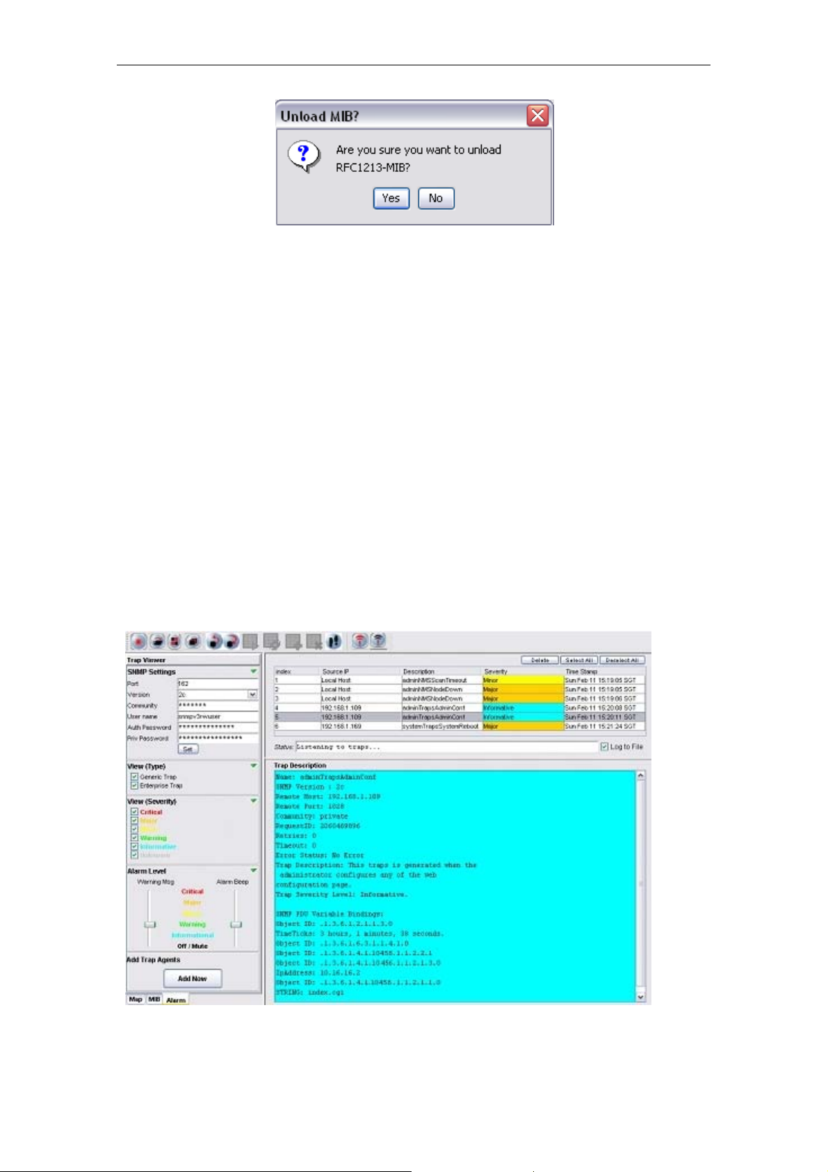
On the other hand, the Unload button next to the Load button would unload the existing MIB
in the tree. Select the unwanted MIB, click on the Unload button. A confirmation dialog box
would turn up, to get confirmation from the user to remove the selected MIB. Click the Yes
button to proceed.
PLANET Mesh Network Manager Guide
Page44 of 124
Page 45
PLANET Mesh Network Manager Guide
4.2.3.24 Alarm Table
The Alarm Table of the PLANET Mesh Network Management Tools enable user to check on
the traps and notifications caught by the trap receiver. The entries are read-only, and shall be
deleted once they were resolved or reviewed.
In order to start listen to the traps, hit the Start button at the toolbar or select Settings > Start
Trap from the menu bar. Select the Stop button, or Settings > Stop Trap to stop the trap
listener. User can change the SNMP Trap community or passwords at the available columns
and hit the Set button. The checkboxes at the bottom of the settings section are the table
filtering options. Clear the selection of the checkbox to hide the relative entry in the trap table.
Each level of severity is represented by a different color.
Select any entry from the alarm table, its description will be displayed at the Trap Description
area at the bottom of the table. If you wish to remove the selected entry, click on the Delete
button.
PLANET Mesh Network Manager Guide
Page45 of 124
Page 46

PLANET Mesh Network Manager Guide
The Alarm Level area is to enable the user to determine the level of the warning message
popup and the alarm beep sound. User may drag the slider to alter the level. For instance,
drag the slider of the warning message to Minor, the warning message would not popup if the
level of the alarm received is Warning or Informational. The following figures illustrate the
example of Warning Message, which will be displayed at the left bottom corner of the screen
when the trap is received.
4.2.3.25 Add Trap Agent
This feature is a wizard window, intended to assist the us er to set one, or more than one node
to be the trap agent of the host system at the NMS, simultaneously.
Hit the Add Now button at the trap viewer mode, to invoke the wizard. At the first page of the
wizard, user will be prompt to enter the IP Address of the desired nodes, to be set as alarm
agent. User can enter the IP Address manually, or select from the drop down list provided.
Click Next to proceed.
PLANET Mesh Network Manager Guide
Page46 of 124
Page 47

PLANET Mesh Network Manager Guide
Then, enter the required SNMP keywords, such as version and community. Click Set to
proceed or Back to back to the first step.
Once the configuration is done, click Proceed button to proceed to reboot page, or Back to
the previous page.
If Proceed is pressed, the following page will be displayed. User may select the IP Address of
the node configured just now to be rebooted. In case if user is wished to reboot the device
manually afterwards, click Reboot Later. On the other hand, hit the Reboot now & Close
button to start reboot the devices.
PLANET Mesh Network Manager Guide
Page47 of 124
Page 48

PLANET Mesh Network Manager Guide
Once the AP unit is rebooted completely, it will contain the information of the Alarm Host
System in the NMS. Hence, it will redirect the alarm message and notification to the NMS
when there is any.
4.2.3.26 View Log Files
There is a feature in the NMS allow the user to back-track the log files of the system. Select
View > View Log Files from the NMS menu bar to invoke a new dialog box, as shown at the
following figures.
Then user can select the type of log to view, including Status Log and Alarm Log. Key in the
desired file name, or hit the button next to the column to select the file, and select the Reload
button to load the content of the file.
PLANET Mesh Network Manager Guide
Page48 of 124
Page 49

PLANET Mesh Network Manager Guide
4.2.3.27 Show Route
When user moves the mouse over the plotted AP unit on the topology map, a small blue
dialog would appear on the screen, displaying the routes of the selected unit. The route
describes how the AP link to the other nodes in the same mesh network, as illustrated by the
figure below.
The figure above shows the node 10.28.43.1 is currently connected directly to 10.30.45.1,
10.22.157.1, and 10.19.49.1.
PLANET Mesh Network Manager Guide
Page49 of 124
Page 50

PLANET Mesh Network Manager Guide
Whereas the figure above illustrates how the routes are displayed when nodes are not directly
connected. From the example, node 10.29.194.1 and 10.22.202.1 are not directly connected.
Instead, the connection between them is established via node 10.27.192.1, according to the
route box.
If user would like to disable this feature, please select Settings > Display Node Route from
the map container menu bar.
PLANET Mesh Network Manager Guide
Page50 of 124
Page 51

PLANET Mesh Network Manager Guide
4.2.3.28 Create VPN Connection
If user would like to scan a network through the backbone line (WAN), a VPN Connection is
required in order to create the communication link between the NMS and the Mesh APs
discovered through a VPN Server.
To create a new VPN Connection, use the New Connection w izard of Windows. In order to
start-up the wizard, open the Network Connections Page (Start Menu > Control Panel >
Network Connections), then select New Connection Wizard. When the wizard turn up,
follow the following steps to do the set up: (*refer to the following screen shots)
Introduction – Welcome page of the wizard
Network Connection Type – Select Connect to the network at my workplace and
click Next button
PLANET Mesh Network Manager Guide
Page51 of 124
Page 52

PLANET Mesh Network Manager Guide
Network Connection – Select Virtual Private Network and click the Next button
Connection Name – Enter a desired Connection Name and hit the Next button
PLANET Mesh Network Manager Guide
Page52 of 124
Page 53

PLANET Mesh Network Manager Guide
Public Network – Select Do not dial initial connection and press Next button
VPN Server Selection – Enter the host name or the IP Address of the VPN Server
that you wish to connect, and click the Next button
PLANET Mesh Network Manager Guide
Page53 of 124
Page 54

PLANET Mesh Network Manager Guide
Complete – Click Finish to complete the set up
After the shortcut is created, user is required to go to the Properties page, by right-click on
the shortcut icon, and then choose from the popup menu. Alternatively, it can be opened from
the Connect page, as shown:
At the Connection Properties window, perform the following steps:
Select the Networking Tab at the top of the page
Select PPTP VPN in the Type of VPN field.
Select the Internet Protocol (TCP/IP) from the available list
PLANET Mesh Network Manager Guide
Page54 of 124
Page 55

PLANET Mesh Network Manager Guide
Hit the Properties button to configure the item’s properties
At the TCP/IP Properties window, select the Advanced.. button, another window
(Advanced TCP/IP Settings) would appear.
At this window, make sure the Use default gateway on remote network option is
checked and click the OK button.
PLANET Mesh Network Manager Guide
Page55 of 124
Page 56

PLANET Mesh Network Manager Guide
Enable the option
The configuration of the VPN is done.
4.2.3.29 Configure Mesh APs
Two methods are available to configure the Mesh AP unit remotely via the NMS,: thru Webbased Configuration Page or launch the AP Configurator. In order to invoke any of these two
methods, right click on any of the active Mesh AP unit on the topology map (gateway or relay).
A popup menu would appear, as shown:
Select the AP Configurator or Web-Based Config option. The following figure shows the
screenshot of the Web-based Configuration page.
PLANET Mesh Network Manager Guide
Page56 of 124
Page 57

PLANET Mesh Network Manager Guide
If the AP Configurator is selected instead, a window would appear to prompt user for the
SNMP password and community, as shown:
(Version 1 and 2C)
(Version 3)
PLANET Mesh Network Manager Guide
Page57 of 124
Page 58

PLANET Mesh Network Manager Guide
After enter the required passwords, click the Proceed button to initiate the AP Configurator. If
the password is incorrect, an error message will show on the screen and ur ge user to reenter
the password accurately. For more details regarding the AP Configurator, please refer to the
next section
.
4.2.3.30 Discovery Tool
The discovery tool is an advance feature added to the NMS. Its main function is used to
discover the recognized AP unit locating in the same subnet. Hit the Discover button at the
bottom to initiate the scan. The APs found throughout the process will be displayed on the
table.
User may click on the entry on the table to view the information regarding the AP, such as
system name, MAC address and so forth. Further more, the selected unit can be configured
by using the drop-down list at the top of the Discover button, to open the AP-Configurator or
Web-based configuration page.
4.2.3.31 View Interface and Client Live Statistic
The new feature added in the latest version of NMS, provides user a graphical and readable
statistic table regarding the target Mesh AP unit. The information that monitored by the live
stat portion includes the interfaces throughput, clients’ throughput, as well as the memory
status.
PLANET Mesh Network Manager Guide
Page58 of 124
Page 59

PLANET Mesh Network Manager Guide
In order to invoke the live stat window, switch the NMS to the Map Container view, and then
look for the Live Stat Settings portion at the left bottom corner. User may enter the IP Address
of the target node (or just click on the node on the map to load the IP) to be monitored, and its
corresponding SNMP Key. Hit the Start Live Stat button to initiate the window.
At the popup live stat window, click the Start Polling button at the top to start the live stat.
The window consists of two parts: the System Stat and the Client Stat. The System Stat page
displays the memory status of the system and the statistic of the interfaces throughput. The
table will be updated at a certain interval, which is set by the Poll Interval field at the Live Stat
Settings corner.
PLANET Mesh Network Manager Guide
Page59 of 124
Page 60

PLANET Mesh Network Manager Guide
The second page shows the throughput statistic of every client that associated to target node.
The results of the transmission and reception data packet rate are displayed in the form of
graph. The table at the bottom of the graphs tabulates the client list with their respective MAC
Address and online time. To stop the polling process, click the End Polling button at the top.
4.2.3.32 Logout Client
With the NMS, the administrator is able to log out and block the user from accessing the
network, by using the Logout and Block user button at the Live Stat Window
In order to remove the client, user must run the Live Stat Window. In the Client Stat portion,
the table at the bottom lists the client that has log on to the network. Select the client (Mac
Address) that to be removed, and hit the Logout and Block user button.
PLANET Mesh Network Manager Guide
Page60 of 124
Page 61

PLANET Mesh Network Manager Guide
A window would appear on the screen to prompt user for the SNMP version to use and its
corresponding community or passwords. Click the Block User button once completed the
step, the selected client will be removed from the active client table, and added into the MAC
Access Table.
PLANET Mesh Network Manager Guide
Page61 of 124
Page 62

PLANET Mesh Network Manager Guide
5 Configure the Mesh AP using AP
Configurator
5.1 Overview of AP Configurator
One of the main features of the PLANET Mesh Network Management Tools is its ability to
configure the Mesh AP remotely. In stead of the Web-Based Configuration page, user can use
the application software that designed specifically for the configuration of the Mesh AP,
namely the AP Configurator.
The AP Configurator utilizes the SNMP protocol to connect the user’s terminal with the AP
over the network. The AP Configurator supports all SNMP version 1, 2C and 3 over UDP.
User may read and write the settings of the hardware through the SNMP agent running on the
device.
The figure below illustrates the screenshot of the AP Configurator:
PLANET Mesh Network Manager Guide
Page62 of 124
Page 63

PLANET Mesh Network Manager Guide
5.2 How to use AP Configurator
This section briefly explains how to configure the AP with the AP Configurator commonly.
Before we proceed, let us have a quick view over the layout of the user interface. Thru the
image at above, there is a tree at the left of the software. The tree lists all the configuration
items in the AP. Click on the item that you wish to view or alter; the relative page will be
loaded in the center frame. On the other hand, the menu bar on the top of the software can be
used to open the configuration page as well.
There is a status bar at the bottom of the page, where it displays the status of the data loading
and setting. In order to set the scalar values, perform the change, and click on the Save
Changes button. The Cancel button is to close the configuration page.
In case to configure any table data, notice that there is a Status drop-down list at the bottom
of every table, as shown:
Select the type of action you would like to perform: add, edit or delete a table row. Then, click
the “>>” button next to the drop-down list. For add and edit operation, an extra area will
appear at the bottom of the drop down list, where it enable user to enter the table data. Hit the
Add or Edit button to complete the operation. The area can be closed by selecting the “X”
button at the top right corner.
PLANET Mesh Network Manager Guide
Page63 of 124
Page 64

PLANET Mesh Network Manager Guide
For delete action instead, select the table entry that wanted to be removed, click the “>>”
button next to the drop-down list. A warning message would appear to prompt user for their
confirmation to proceed with the operation. Hit Yes to proceed.
The Refresh button at the top of every table is used to reload the table.
PLANET Mesh Network Manager Guide
Page64 of 124
Page 65

PLANET Mesh Network Manager Guide
5.3 Configure the Mesh AP
At this section, we will look into every configuration pages of the Mesh AP one by one, and
briefly describe the parameters in the pages.
5.3.1.1 System > System
The System page is the general settings page of the AP.
Parameters:
1) System Name
• The generic name of the Mesh AP unit.
• Data type: Display String
2) System Location
• The generic physical location name of the Mesh AP Unit
• Data type: Display String
3) System Mode
• The operation mode of the Mesh AP unit
• Options: Gateway, Relay, Client-relay, Layer 2 Gateway, Layer 2 Relay
Gateway Layer 3 Gateway Mode. In a Mesh network Gateway mode is the
path to the Internet for the whole Mesh network behind.
WAN port is active and will be used for Internet Connection.
Three types of Internet connection will be available, please refer
PLANET Mesh Network Manager Guide
Page65 of 124
Page 66

PLANET Mesh Network Manager Guide
to section 3.3.2 for more.
Relay Layer 3 Relay Mode. Relay mode can help to route between
mesh backhaul and local WiFi/LAN network. Also, a Relay mode
Mesh AP can help to route the packets from other Relay node to
the destination IP subnet or Gateway.
WAN port is disabled at this mode. At the same time no WAN
setting is required.
Client-Relay Layer 3 Client-Relay Mode.
At this mode, the Mesh node can only route between local
WiFi/LAN network to mesh backhaul. It will not help to route
packets from other Relay node. This mode can be used to reduce
the unnecessary routing especially if this Mesh node is in the
edge of the whole mesh topology.
Layer 2 Gateway Layer 2 Gateway Mode.
At this mode, the Mesh AP can be viewed as a bridge. This
bridge can bridge between WAN, LAN, Mesh backhaul, and WiFi.
As a Gateway, the WAN interface will turns into the public bridge
port that connects to the existing Ethernet network.
Be noted, only ONE Gateway is allowed in the same Mesh
network.
Layer 2 Relay Layer 2 Relay Mode.
4) Contact Name
• The name of the contact person / network administrator
• Data type: Display String
5) Contact Email
• The E-mail address of the contact person / network administrator
• Data type: Display String
6) Contact Phone
• The phone number of the contact person / network administrator
• Data type: Display String
7) Description
At this mode, the Mesh node act as a mesh relay that can bridge
between WAN, LAN, Mesh backhaul and WiFi.
• A short description regarding the managed device (Mesh AP)
• Data type: Display String
8) Object ID
• The Object ID (OID) of the Mesh AP specified to support the SNMP service
PLANET Mesh Network Manager Guide
Page66 of 124
Page 67

PLANET Mesh Network Manager Guide
• Read-only data
5.3.1.2 System > Syslog
The Syslog is a system feature to send the system log messages to a remote server.
Parameter
1) Enable Syslog
• A checkbox to enable or disable the syslog feature.
2) KLOG
• A checkbox to enable or disable the Kernel Log service
3) Enable Remote Syslog
a. A checkbox to enable or disable the remote syslog server service
4) Remote Syslog Address
• The address of the remote syslog server, who will receive all the syslog message
• Data type: DNS String
5.3.1.3 System > Advanced Tuning
The Advance Tuning panel is divided to two parts, the connection tracking parameters and
the wireless distance. The Connection tracking portion determines the seconds of various
timeout parameters, where as the latter define the estimate operating distance in meters, for
the radio available in the device. Use the reset button to refill the value fields with the default
values.
PLANET Mesh Network Manager Guide
Page67 of 124
Page 68

PLANET Mesh Network Manager Guide
Parameters:
1) Maximum session
• Maximum allowable IP connection tracking session.
• Range: 4096 ~ 212368; Default: 10000 sessions
2) Generic Timeout
• Timeout value in seconds (s) for generic connection track entry.
• Range: 50 ~ 1200; Default: 600 seconds.
3) ICMP Timeout
• Timeout value in seconds (s) for ICMP entry.
• Range: 10 ~ 60; Default: 30 seconds.
4) TCP Close Timeout
• Timeout value in seconds (s) for TCP close.
• Range: 5 ~ 30; Default: 10 seconds.
5) TCP Close Wait Timeout
PLANET Mesh Network Manager Guide
Page68 of 124
Page 69

PLANET Mesh Network Manager Guide
• Timeout value in seconds (s) for TCP close wait.
• Range: 10 ~ 120; Default: 60 seconds.
6) TCP Established Timeout
• Timeout value in seconds (s) for established TCP.
• Range: 600 ~ 864000; Default: 3600 seconds.
7) TCP Finished Wait Timeout
• Timeout value in seconds (s) for TCP finished wait.
• Range: 10 ~ 3600; Default: 120 seconds.
8) TCP Last ACK Timeout
• Timeout value in seconds (s) for TCP last acknowledgement.
• Range: 10 ~ 60; Default: 30 seconds.
9) TCP SYN Receive Timeout
• Timeout value in seconds (s) for TCP SYN receive.
• Range: 10 ~ 120; Default: 60 seconds.
10) TCP SYN Sent Timeout
• Timeout value in seconds (s) for TCP SYN sent.
• Range: 10 ~ 240; Default: 120 seconds.
11) TCP Time Wait Timeout
• Timeout value in seconds (s) for TCP time wait.
• Range: 10 ~ 240; Default: 120 seconds.
12) UDP Timeout
• Timeout value in seconds (s) for UDP.
• Range: 10 ~ 60; Default: 30 seconds.
13) UDP Stream Timeout
• Timeout value in seconds (s) for UDP stream.
• Range: 10 ~ 360; Default: 180 seconds.
14) Radio 1 distance
• Specify the operating radius in meter (m) of radio 1.
• Range: 100 ~ 10000; Default: 400 meters.
15) Radio 2 distance
• Specify the operating radius in meter (m) of radio 2.
• Range: 100 ~ 10000; Default: 400 meters.
16) Country
• Select the operating country of the wireless interface.
17) Outdoor Mode
• Enable or Disable the outdoor mode for the wireless interface.
• Default: Enable.
18) External Channel Mode
• Enable or Disable the external channel mode for the wireless interface.
PLANET Mesh Network Manager Guide
Page69 of 124
Page 70

PLANET Mesh Network Manager Guide
• Default: Disable.
5.3.1.4 Network > Network
The network panel defines the DNS settings. This DNS service translates the domain name
into IP Address form, which recognized by the Internet. If the primary server failed to perform
the translation, the secondary server will take over the process.
Parameters:
1) Primary DNS
• Define the Primary DNS Server IP Address.
• Data Type: IP Address
2) Secondary DNS
• Define the secondary DNS Server IP Address
• Data type: IP Address
3) Domain
• An optional domain name for the DNS client
• Data type: DNS String
4) Default Gateway
• The default gateway IP Address for the static IP Address
• Data type: IP Address
PLANET Mesh Network Manager Guide
Page70 of 124
Page 71

PLANET Mesh Network Manager Guide
5.3.1.5 Network > WAN
Define the type of WAN interface to use. Three options are available: Static, DHCP, and
PPPoE. If user wishes to change the type to dynamic, select the DHCP, then click the Save
Changes button. If Static or PPPoE is selected instead, the Configure button will lead the
user to the configuration page of the type.
• Network > WAN > Static
Enter the Static IP Address and its netmask, click the Save Changes button to activate the
Static WAN interface type. Hit the Back to go back to the WAN Type configuration page.
Parameters:
1) IP Address
PLANET Mesh Network Manager Guide
• The static IP Address for the WAN interface
• Data type: IP Address
Page71 of 124
Page 72

PLANET Mesh Network Manager Guide
2) Netmask
• The netmask for the Static IP Address.
• Data type: IP Address
• Network > WAN > PPPoE
Fill in the PPPoE’s username and password, then click the Save Changes button to activate
the PPPoE WAN interface type. Hit the Back button to back to the WAN Type configuration
page.
Parameters:
1) Enable PPPoE
• A checkbox to enable or disable the PPPoE service.
2) Username
• The username of the PPPoE client
• Data type: Display String
3) Password, Confirm
• The password corresponding to the username of the PPPoE client
• Must key in the same input at the Confirm field to avoid mistakes
• Data type: Display String
PLANET Mesh Network Manager Guide
Page72 of 124
Page 73

PLANET Mesh Network Manager Guide
• Network > WAN > Add VLAN Tag
Note that there is an Add VLAN Tag button at the WAN page. Press the button would open
the VLAN Tag page, where user may define the VLAN ID for a desired WAN interface.
1. If your Ethernet network that connect to WAN port supports VLAN
Note
tagging and you plan to make the Mesh Network route for different
purpose, you can use the “Add VLAN Tag” button to create different
VLAN for WAN interface.
2. Only the default WAN is un-tagged. Any other newly inserted WAN
interface will be tagged follow the ID setting that range from 1 to 4095.
Maximum is 15 virtual WAN interfaces are allowed.
Parameters (VLAN Tag List columns)
1) ID
• The VLAN-ID
• Data type: Integer, in between 1 and 4096
2) Type
• The type of the WAN-VLAN defined.
PLANET Mesh Network Manager Guide
Page73 of 124
Page 74

PLANET Mesh Network Manager Guide
• Available option: Static and DHCP
3) IP
• The IP Address of the interface.
• This field is disabled if the Type chosen is DHCP
• Data type: IP Address
4) Subnet
• The corresponding subnet for the IP Address of the interface.
• This field is disabled if the Type chosen is DHCP
• Data type: IP Address
5) Comment
• Optional comment regarding the table entry
• Data type: Display String
6) Status
• Enable or disable the table entry.
• Available option: Enable and Disable
Hit the Back button to go back to the WAN-Type page.
PLANET Mesh Network Manager Guide
Page74 of 124
Page 75
PLANET Mesh Network Manager Guide
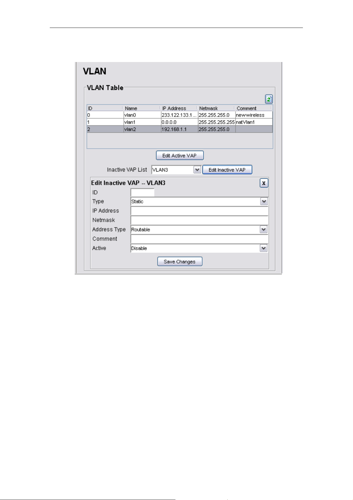
5.3.1.6 Network > VLAN
The page is displaying the VLAN Table which is showing the activated VAP of the Mesh AP.
There are total of 16 VLANs available in the device. In order to activate an inactive VAP,
choose an entry from the Inactive VAP List, then click the Edit Inactive VAP button. Then the
Edit Inactive VAP – VLANx panel would appear. Similarly, to edit or disable an active VAP,
user can select the entry from the table, and hit the Edit Active VAP. Fill in the following
parameters:
1) ID
• The ID for the VLAN interface.
• The value is ranged between 1 to 4095, where 0 is reserved for VLAN0
2) Type
• The type of the VLAN
• The available options are static and dynamic
PLANET Mesh Network Manager Guide
Page75 of 124
Page 76

PLANET Mesh Network Manager Guide
3) IP Address
• The IP Address of the selected VLAN interface
4) Netmask
• The Netmask for the IP Address
5) Address Type
• The type of the IP Address, either NAT or Routable
6) Comment
• An optional comment regarding the table entry
7) Active
• The status of the VAP
• Set to Active to enable an inactive VAP; set to Inactive to disable an active VAP.
Finally click the Save Changes button to commit the changes.
1. ONLY VLAN 0, the default VLAN, is un-tagged packets. For VLAN 1 to
Note
VLAN 15, it will be tagged packets at LAN interface after it is enabled.
And for Wireless interface, different SSID are required for different
VLAN.
2. The connected LAN device should support VLAN tagging if you plan to
connect wired device for different VLAN.
PLANET Mesh Network Manager Guide
Page76 of 124
Page 77

PLANET Mesh Network Manager Guide
5.3.1.7 Network > Mesh
The Mesh configuration page read the data from the wireless interface, ath0. Select the
Wireless Settings button to view or edit the corresponding data.
Parameters (Mesh Configuration)
1) IP Address
• IP Address for the Mesh interface
• Data type: IP Address
2) Netmask
• Netmask for the IP Address of the Mesh interface
• Data type: IP Address
3) Comment
PLANET Mesh Network Manager Guide
Page77 of 124
Page 78

PLANET Mesh Network Manager Guide
• An optional comment regarding the Mesh interface
• Data type: Display String
4) Active
• The status of the Mesh interface, either active or inactive.
Parameters (Wireless Settings)
1) MAC Address
• The Mac Address of the Mesh interface
• This is a read-only parameter
2) Mode
• Define the mode of the Mesh interface
• In this case, the mode is fixed to AD-HOC
3) Band
• The band to use
• Three options available: 802.11a, 802.11b, and 802.11g
4) ESSID
• The identifying name of a wireless access point’s network
• Data type: Display String
5) Frequency
• The operating frequency of the ath0 wireless network interface in Mega Hertz.
6) Beacon Interval
• The beacon interval in milliseconds
• Data type: Integer, in between 20 and 1000
• Default value is 100
7) RTS Threshold
• The RTS Threshold value
• Data type: Integer, in between 256 and 2346
• Default value is 2346
8) Fragment Threshold
• The Fragment Threshold value
PLANET Mesh Network Manager Guide
Page78 of 124
Page 79

PLANET Mesh Network Manager Guide
• Data type: Integer, even number only, in between 1500 and 2346
• Default value is 2346
9) DTIM Interval
• Data type: Integer, in between 1 and 256
• Default value is 1
10) Data Rate
• Select the data rate of the interface from the list
• Available selection: Auto, 1, 2, 5.5, 6, 9, 11, 12, 18, 24, 36, 48, 54 Mbps
11) TX Antenna
• The properties of the transmission antenna
• Available selection: Diversity, Port1, Port2 and Card Default
12) RX Antenna
• The properties of the reception antenna
• Available selection: Diversity, Port1, Port2 and Card Default
13) Current Tx Power (dBm)
• This is a read-only field indicating the current transmission power used by the
mesh interface.
• The value is in the unit of dBm
14) Tx Power (dBm)
• The transmission power field, where user can alter the level of power through the
selection available.
• The default value for this field is Max, which will use the maximum power level of
the wireless interface.
15) Security
• The security type to be used by the wireless network, wither open, WEP, or AES
16) Encryption Key
• The encryption key used in corresponding to the security type used.
• Data type: Octet String
PLANET Mesh Network Manager Guide
Page79 of 124
Page 80

PLANET Mesh Network Manager Guide
5.3.1.8 Network > Wireless Configuration
The upper portion of the Wireless Configuration page is displaying the common settings of all
the wireless interfaces. The parameters here will be applied to all the VAP. The table in the
page is showing the list of virtual APs. User can only edit the information in the table.
Parameters (Common Settings)
1) MAC Address
• The Mac Address of the Wireless interface
• This is a read-only parameter
2) Mode
• The Mode is fixed to AP
3) Band
• The band to use
PLANET Mesh Network Manager Guide
Page80 of 124
Page 81

PLANET Mesh Network Manager Guide
• Three options available: 802.11a, 802.11b, and 802.11g
4) Frequency
• The operating frequency of the ath1 wireless network interface in Mega Hertz
5) TX Antenna
• The properties of the transmission antenna
• Available selection: Diversity, Port1, Port2 and Card Default
6) RX Antenna
• The properties of the reception antenna
• Available selection: Diversity, Port1, Port2 and Card Default
7) Current Tx Power (dBm)
• This read-only field indicating the current transmission power level used by the
wireless interface.
• The value is in the unit of dBm
8) Tx Power (dBm)
• The transmission power level of the wireless interface
• The default value is Max, where the device will tune the transmission power to
the maximum level of the wireless interface.
Click the Save Changes button to commit the common configurations.
Parameters (Virtual AP list)
1) ESSID
• The Enhanced Service Set Identifier of the wireless network
• Data type: Display String
2) Broadcast SSID
• Enable or disable the SSID to be broadcasted.
3) Beacon Interval
• The beacon interval in milliseconds
• Data type: Integer, in between 20 and 1000
• Default value is 100
PLANET Mesh Network Manager Guide
Page81 of 124
Page 82

PLANET Mesh Network Manager Guide
4) RTS Threshold
• The RTS Threshold value
• Data type: Integer, in between 256 and 2346
• Default value is 2346
5) Fragment Threshold
• The Fragment Threshold value
• Data type: Integer, even number only, in between 1500 and 2346
• Default value is 2346
6) DTIM Interval
• DTIM Interval
• Data type: Integer, in between 1 and 256
• Default value is 1
7) Data Rate
• Select the data rate of the interface from the list
• Available selection: Auto, 1, 2, 5.5, 6, 9, 11, 12, 18, 24, 36, 48, 54 Mbps
8) Security
• The security type, can be either Open, WEP, WPA1, WPA2, and WPA1&2
9) WPA-Type
• The type of the WPA security mode
• Available options: TKIP and AES
• This field is only writable if the security type WPA is selected
10) 802.1x
• Enable or disable the use of Radius Server as authenticator
• This field is only enabled if WEP or WPA is selected
11) Encryption Key
• The encryption key depends on the type of security mode using
• This field is only enabled if WEP or WPA is selected
PLANET Mesh Network Manager Guide
Page82 of 124
Page 83

PLANET Mesh Network Manager Guide
5.3.1.9 Network > Route
The route table is a network map that notifies the node about the way to deliver the packets to
its addressee. This configuration page presents the routing table of the Mesh AP.
Parameters:
1) Subnet
• The subnet address of the route
• Data type: IP Address
2) Netmask
• The netmask corresponding to the subnet address
• Data type: IP Address
3) Gateway
• The gateway IP Address for this route entry
• Data type: IP Address
4) Device
• Specifies the route devices for this route entry
• Data type: Octet String
PLANET Mesh Network Manager Guide
Page83 of 124
Page 84

PLANET Mesh Network Manager Guide
5) Direct
• Select the type of routing, either direct or indirect.
• Direct type using device, whereas indirect is using the two hope gateway
6) Comment
• An optional comment regarding the route table entry
• Data type: Display String
7) Status
• Specify the status of the route entry, enable or disable.
5.3.1.10 Network > IP Sec
The IP Sec configuration page enable user to alter the setting of the IP Security Protocol. With
IPSec, a security “tunnel” is created between the source and destination point, allow the
packet to be sent through the “tunnel”. In this page, user can define the characteristics,
including the certificate key and RSA key, of the tunnel.
Parameters:
1) Enable IP Sec
• A checkbox to enable or disable the IPSec service.
2) Type
PLANET Mesh Network Manager Guide
Page84 of 124
Page 85

PLANET Mesh Network Manager Guide
• Select the type of the IPSec protocol.
• Available selection:
o x509
o RSA
o PSK
3) Local ID
• The identifier of the local host.
• Data type: Octet String
4) Remote ID
• The identifier of the remote host at the other end
• Data type: Octet String
5) Remote IP Address
• The IP Address of the remote host.
• Data type: IP Address
6) Remote Subnet, Remote Netmask
• The Subnet where the remote host is located at, with its correspond netmask
• Data type: IP Address
7) Local Certificate Password
• The x.509 certificate pem passphrase, used when IPSec type x509 is
selected
• Data type: Octet String
8) Local RSA Key
• The RSA Key of the local host, used when IPSec type RSA is selected
• Data type: Octet String
9) Remote RSA Key
• The RSA Key of the remote host, used when IPSec type RSA is selected
• Data type: Octet String
10) PSK
• The PSK Key, used when IP Sec type PSK is selected
• Data type: Octet String
PLANET Mesh Network Manager Guide
Page85 of 124
Page 86

PLANET Mesh Network Manager Guide
5.3.1.11 Network > L2TP Client
The L2TP (Layer 2 Tunneling Protocol) is a tunneling protocol that used to support the virtual
private network. Admin can create a L2TP client at this panel for the network traffic tunneling
purpose.
Parameters
1) Enable L2TP Client Service
• A checkbox to enable or disable the L2TP feature
2) LNS Address
• The L2TP Network Server address.
• Data type: DNS String
3) Username
• The username for the L2TP client
• Data type: Display String
4) Password
• The correspond password for the username above
• Data type: Display String
PLANET Mesh Network Manager Guide
Page86 of 124
Page 87

PLANET Mesh Network Manager Guide
5.3.1.12 Network > OLSR
The OLSR configuration page defines the Optimized Link State Routing protocol of the Mesh
AP. It is a routing protocol for the Layer 3 mesh backhaul connections.
Parameters
1) Enable OLSR
• A checkbox to enable the OLSR service
2) TOS Value
• This field define the type of service value that should be set in the OLSR
control traffic packet IP headers
• Data type: Integer
3) Enable Willingness
• A checkbox to enable the willingness of the Mesh AP.
• Willingness of an AP is defined as the readiness of a node to carry and
forward traffic for other nodes.
4) Willingness Level
• The level of the willingness.
• Data type: Integer (0-7)
PLANET Mesh Network Manager Guide
Page87 of 124
Page 88

PLANET Mesh Network Manager Guide
5) Enable Hysteresis
• A checkbox to enable the hysteresis of the Mesh AP
• Link hysteresis determines the criteria at which a link to a neighbour is
accepted or rejected. Hys teresis adds more robustness to the link sensing,
but delays the neighbour registration.
6) Hysteresis Scaling
• The level scale of the hysteresis
• Data type: Float (0.0 ~ 1.0)
7) Hysteresis THR High
• The upper limit (threshold high) of the hysteresis
• Data type: Float (0.0 ~ 1.0)
8) Hysteresis THR Low
• The lower limit (threshold low) of the hysteresis
• Data type: Float (0.0 ~ 1.0)
9) Link Quality Type
• The type of link quality
• Available options:
o Disable
o Use for MPR selection
o Use for MPR selection and Routing
10) Link Quality Size
• The Link quality window size
• Data type: Integer, default size is 10
11) Poll Rate
• The polling rate, where the value is in the interval of 0 and 1
• Data type: Float
12) TC Rate
• The TC redundancy specifies the level of neighbour information should be
sent in a TC message.
• Available options:
PLANET Mesh Network Manager Guide
Page88 of 124
Page 89

PLANET Mesh Network Manager Guide
o Send only MPR Selectors
o Send only MPR Selectors and MPRs
o Send all neighbours
13) MPR
• This field specifies how many MPRs a node should try select to reach every
2hop neighbour
• Data type: Integer, default value is 1
14) Shared Key
• The secret shared key.
• User must re-enter the same password at the Confirm field to set this field
• Data type: Display String
Unless you are familiar with the setting, otherwise we would suggest to
Note
keep the value unchanged, or press Reset to set back to default. These
settings should fit for the most application.
5.3.1.13 Services > NTP
The NTP service implements the Network Time Protocol to the Mesh APs to synchronize the
system time to some time reference. The NTP Table in this page lists the NTP server that is
used by the device.
PLANET Mesh Network Manager Guide
Page89 of 124
Page 90

PLANET Mesh Network Manager Guide
Parameters
1) Enable NTP Service
• A checkbox to enable the NTP service of the system
2) Time Zone
• A list of time zones is available in the drop down list. Select the appropriate
one to synchronize.
Parameters (NTP Table columns)
1) Server
• The NTP server host name
• Data type: DNS String
2) Min Pool
• The minimum pool time of the server, in seconds
• Data type: Integer, default value is 4
3) Max Pool
• The maximum pool time of the server, in seconds
• Data type: Integer, default value is 10
4) Comment
• An optional comment regarding the NTP Table entry
• Data type: Display String
5) Active
• The status of the NTP Table entry, either active or inactive
PLANET Mesh Network Manager Guide
Page90 of 124
Page 91

PLANET Mesh Network Manager Guide
5.3.1.14 Services > DHCP
The DHCP service offers the Mesh AP a feature to assign dynamic IP Address to all the
clients. The DHCPD Table in this configuration page lists the dynamic IP assignments in the
device.
Parameters (DHCPD Table columns)
1) Iface
• The name of the active interface in the Mesh AP unit.
• Data type: Octet String
2) Subnet
• The subnet address
• Data type: IP Address
3) Netmask
• The netmask corresponding to the subnet of the table entry
• Data type: IP Address
4) Net Start
• The starting IP Address in the subnet for the assignment.
• Data type: IP Address
PLANET Mesh Network Manager Guide
Page91 of 124
Page 92

PLANET Mesh Network Manager Guide
5) Net End
• The last IP Address in the subnet for the assignment
• Data type: IP Address
6) Max Lease Time
• The maximum duration for the client to retain its current IP Address
• Data type: Integer, in the range of 600 to 864000 seconds
7) Default Lease Time
• The lease time defined for the client to retain its current IP Address. Once the
time is up, the IP Address will be released.
• Data type: Integer, in the range of 600 to 864000 seconds
8) Domain
• The domain name for the DHCP Server
• Data type: DNS String
9) DNS
• The IP Address of the DNS server of the subnet
• Data type: IP Address
10) Router
• The router IP Address of the subnet
• Data type: IP Address
11) Comment
• An optional comment for the particular table entry
• Data type: Display String
12) Status
• The status of that particular table entry, either active or inactive
PLANET Mesh Network Manager Guide
Page92 of 124
Page 93

PLANET Mesh Network Manager Guide
5.3.1.15 Services > MAC Access
The Mac Access feature of the Mesh AP provides a filtering method to limit the accessing of
the client. User can set the Mac Access Table to deny or inversely, allow the client that
defined with their Mac Address to attach to the network.
Parameters:
1) Enable MAC Access
• A checkbox to enable or disable the MAC Access feature
2) Filter Type
• Define the filter type of the user not listed in the MAC Access Table, either to
allow or deny the client entries to access the network.
Parameters (MAC Access Table)
1) Mac Address
• The Mac Address of the client to be filtered.
• Data type: Mac Address
PLANET Mesh Network Manager Guide
Page93 of 124
Page 94

PLANET Mesh Network Manager Guide
2) Type
• Define the type of control for the corresponding Mac Address, either Allow or
Deny
3) Comment
• An optional comment regarding the client
• Data type: Display String
4) Active
• The status of the table entry, either active or inactive
The Browse Active Users button opens a list that shows every active user associating to the
network. From this table, the administrator may add the desired user into the Mac Access
Table, by using the Update button. Choose the type of accessing from the drop down list.
PLANET Mesh Network Manager Guide
Page94 of 124
Page 95

PLANET Mesh Network Manager Guide
5.3.1.16 Services > NAT
The Network Address Translation service enables the clients with IP addresses that are not
globally unique to connect to the network by translating those addresses into a globally
routable IP address space.
Parameters
1) Enable NAT Service
Parameters (NAT Table column)
1) Protocol
• A checkbox to enable or disable the NAT service
• Protocol to use. Choose from UDP, TCP and Both
2) Port
• The port number to forward to.
• Data type: Integer, in the range of 1 to 65535
3) IP Address
• The destination host IP Address
• Data type: IP Address
PLANET Mesh Network Manager Guide
Page95 of 124
Page 96

PLANET Mesh Network Manager Guide
4) Comment
• An optional comment regarding the selected table entry
• Data type: Display String
5) Active
• The status of the selected table entry, either active or inactive
5.3.1.17 Services > Firewall
The Firewall service is the security feature that included in the Mesh AP to limit certain type of
traffic. User can define and add a firewall rule through this configuration page.
Parameter
1) Enable Firewall Service
• A checkbox to enable or disable the firewall service
Parameters (Firewall Table columns)
1) Target
• Define the type of the firewall rule, allow or deny the traffic
2) Source Iface
• The source interface of the firewall rule.
• Data type: Octet String
PLANET Mesh Network Manager Guide
Page96 of 124
Page 97

PLANET Mesh Network Manager Guide
3) Destination Iface
• The destination interface of the firewall rule
• Data type: Octet String
4) Source IP & Mask
• The IP Address and its netmask of the source interface
• Data type: IP Address
5) Destination IP & Mask
• The IP Address and its netmask of the destination interface
• Data type: IP Address
6) Protocol
• The protocol of the rule.
• Data type: Integer, in the range of 0 to 255
7) Start Port & End Port
• The start and end define the range of port.
• Data type: Integer, in the range of -1 to 65535
• Fill the fields with ‘-1’ if the ports is not applicable
8) Comment
• An optional comment regarding the firewall rule
• Data type: Display String
9) Active
• The status of the firewall rule, either active or inactive
PLANET Mesh Network Manager Guide
Page97 of 124
Page 98

PLANET Mesh Network Manager Guide
5.3.1.18 Services > Traffic Shaping
User can set the download and upload speed at the Traffic Shaping configuration page in
order to alter the network performance. The Traffic Shaping Table defines the traffic volume
for a port with a specified protocol.
Parameters
1) Enable Traffic Shaping service
• A checkbox to enable or disable the Traffic Shaping service on the Mesh AP
2) WAN Uplink Speed
• Define the upload speed of the WAN interface
• Data type: Integer, in the range of 5 and 100 Mbps
PLANET Mesh Network Manager Guide
Page98 of 124
Page 99

PLANET Mesh Network Manager Guide
3) WAN Downlink Speed
• Define the download speed of the WAN interface
• Data type: Integer, in the range of 5 and 100 Mbps
4) User Uplink Speed
• Define the user default upload speed.
• Data type: Integer, in the range of 32 and 65535 kbps
5) User Downlink Speed
• Define the user default download speed
• Data type: Integer, in the range of 32 and 65535 kbps
Parameters (Traffic Shaping Table)
1) Protocol
• The protocol to use.
• Available choice: UDP, TCP and Both
2) Port
• The port number
• Data type: Integer, in the range of 1 and 65535
3) Min Size
• The minimum size of the data packet
• Data type: Integer, in the range of 1 and 65535
4) Max Size
• The maximum size of the data packet
• Data type: Integer. in the range of 1 and 65535
5) Priority
• The priority to be assigned to the rule
• Available choice: Background, Video, Voice and Best Effort
6) Comment
• An optional comment regarding the table entry
• Data type: Display String
7) Status
PLANET Mesh Network Manager Guide
Page99 of 124
Page 100

PLANET Mesh Network Manager Guide
• The status of the table entry, either active or inactive
5.3.1.19 Services > PPTP Server
The Point-to-Point Tunneling Protocol is best suits for remote access applications of VPNs.
The PLANET Mesh Network Management Tools required a VPN connection to monitor the
mesh network remotely. Hence a PPTP server is required. The PPTP Server is used to assign
a user to a specified IP Address.
Parameters:
1) Enable PPTP Server Service
• A checkbox to enable or disable the PPTP server service.
2) Server IP
• The IP Address of the PPTP Server
• Data type: IP Address
PLANET Mesh Network Manager Guide
Page100 of 124
 Loading...