

Page 1

Mobile IP Roaming Gateway
MAP-2105
User’s Manual
1
Page 2

Copyright
Copyright (C) 2006 PLANET Technology Corp. All rights reserved.
The products and programs described in this User’s Manual are licensed products of PLANET
Technology, This User’s Manual contains proprietary information protected by copyright, and this
User’s Manual and all accompanying hardware, software, and documentation are copyri ghted.
No part of this User’s Manual may be copied, photocopied, reproduced, translated, or reduced to
any electronic medium or machine-readable form by any means by electronic or mechanical.
Including photocopying, recording, or information storage and retrieval systems, for any purpose
other than the purchaser's personal use, and without the prior express written permission of
PLANET Technology.
Disclaimer
PLANET Technology does not warrant that the hardware will work properly in all environments
and applications, and makes no warranty and representation, either implied or expressed, with
respect to the quality, performance, merchantability, or fitness for a particular purpose.
PLANET has made every effort to ensure that this User’s Manual is accurate; PLANET disclaims
liability for any inaccuracies or omissions that may have occurred.
Information in this User’s Manual is subject to change without notice and does not represent a
commitment on the part of PLANET. PLANET assumes no responsibility for any inaccuracies that
may be contained in this User’s Manual. PLANET makes no commitment to update or keep
current the information in this User’s Manual, and reserves the right to make improvements to this
User’s Manual and/or to the products described in this User’s Manual, at any time without notice.
If you find information in this manual that is incorrect, misleading, or incomplete, we would
appreciate your comments and suggestions.
FCC Compliance Statement
This equipment generates and uses radio frequency energy and if not installed and used properly,
that is, in strict accordance with the instructions provided with the equipment, may cause
interference to radio and TV communication. The equipment has been tested and found to
comply with the limits for a Class A computing device in accordance with the specifications in
Subpart B of Part 15 of FCC rules, which are designed to provide reasonable protection against
such interference in a residential installation. However, there is no guarantee that interference will
not occur in a particular installation. If you suspect this equipment is causing interference, turn
your Ethernet Switch on and off while your radio or TV is showing interference, if the interference
disappears when you turn your Ethernet Switch off and reappears when you turn it back on, there
is interference being caused by the Ethernet Switch.
You can try to correct the interference by one or more of the following measures:
Reorient the receiving radio or TV antenna where this may be done safely.
To the extent possible, relocate the radio, TV or other receiver away from the Switch.
Plug the Ethernet Switch into a different power outlet so that the Switch and the receiver are
on different branch circuits.
If necessary, you should consult the place of purchase or an experienced radio/television
technician for additional suggestions.
CE mark Warning
The is a class B device, In a domestic environment, this product may cause radio interference, in
which case the user may be required to take adequate measures.
2
Page 3

Trademarks
The PLANET logo is a trademark of PLANET Technology. This documentation may refer to
numerous hardware and software products by their trade names. In most, if not all cases, these
designations are claimed as trademarks or registered trademarks by their respective companies.
Revision
User’s Manual for PLANET Mobile IP Roaming Gateway:
Model: MAP-2105
Rev: 1.0 (July 2006)
Part No.: EM-MAP2105
3
Page 4

TABLE OF CONTENTS
Chapter 1 Introduction .......................................................................................1
1.1 Features......................................................................................................1
1.2 Package Contents.......................................................................................1
1.3 Network Planning ........................................................................................1
1.4 Hardware Installation ...................................................................................2
1.5 Startup the MAP-2105.................................................................................2
Chapter 2 Basic Network Setup.........................................................................4
Chapter 3 Web Configuration ............................................................................8
3.1 System Settings ........................................................................................10
3.2 Network.....................................................................................................12
3.2.1 WAN ...................................................................................................12
3.2.2 Route..................................................................................................14
3.3 Local Service.............................................................................................16
3.3.1 MLRD..................................................................................................16
3.3.2 VPN Client..........................................................................................17
3.3.3 NTP.....................................................................................................18
3.4 System Management ................................................................................19
3.4.1 Password............................................................................................19
3.4.2 SNMP .................................................................................................19
3.4.3 Syslog Server .....................................................................................22
3.5 Tools .........................................................................................................23
3.5.1 Ping.....................................................................................................23
3.5.2 Download............................................................................................24
3.5.3 Firmware Update ................................................................................25
3.5.4 Settings...............................................................................................26
3.6 Reboot.......................................................................................................28
3.7 Reset.........................................................................................................28
3.8 Status........................................................................................................28
3.8.1 System................................................................................................29
3.8.2 Interfaces............................................................................................30
3.8.3 Services..............................................................................................32
3.8.4 MLRD..................................................................................................32
3.8.5 Route..................................................................................................33
3.8.6 Syslog.................................................................................................34
Chapter 4 Management Utility .........................................................................35
4.1 Installation and Un-installation...................................................................35
4.1.1 To install the MLRD Management Suite .............................................35
4.1.2 To Uninstall the MLRD Management Suite.........................................38
4.2 How to use MLRD Management Suite ......................................................39
4.2.1 AP Finder............................................................................................39
4.2.2 Trap Viewer ........................................................................................40
4.2.3 MLRD Manager ..................................................................................42
4.3 Node Configuration using MLRD Manager................................................44
4.3.1 File >Change SNMP Password ..........................................................44
4
Page 5

4.3.2 Status > System..................................................................................45
4.3.3 Status > MLRD ...................................................................................46
4.3.4 Config > System .................................................................................47
4.3.5 Config > Network > WAN....................................................................48
4.3.6 Config > Network > Route...................................................................51
4.3.7 Config > Management > SNMP Password .........................................53
4.3.8 Config > Management > Access Control ............................................55
4.3.9 Config > Management > Remote Syslog............................................56
4.3.10 Config > Services > NTP-Client........................................................56
4.3.11 Config > Services > Mobile IP...........................................................57
4.3.12 Config > Services > VPN-Client........................................................58
4.3.13 Commnad > Download/Upload.........................................................60
4.3.14 Command > Reboot..........................................................................60
4.3.15 Command > Reset............................................................................61
4.3.16 Help > About.....................................................................................61
5
Page 6

Chapter 1 Introduction
The MAP-2105 is a mobile IP roaming gateway which is specifically designed for PLANET
wireless mesh network. It offers the full “mobility” to all users. Not like the layer-2 only capability in
ordinary AP, the “mobility” defined in MAP-2105 is the ability of a user to change its attached
node from one mesh AP to another while maintaining all existing communications and using the
same IP address at this new link. Remote printing, remote login, VoIP sessions, and file transfers
are some examples of applications whose communications are undesirable to interrupt when a
mobile user moves from node to node.
1.1 Features
• Provides Mobile IP capability for all wireless clients in the MESH network
• Secured HTTP management
• Supports VPN client
• Optimized for up to 500 mobile users
1.2 Package Contents
The following items should be included:
• MAP-2105 x 1
• Power Adapter x 1
• Quick Start Guide x 1
• Management Utility and User's manual CD x 1
If any of the above items are damaged or missing, please contact your dealer immediately.
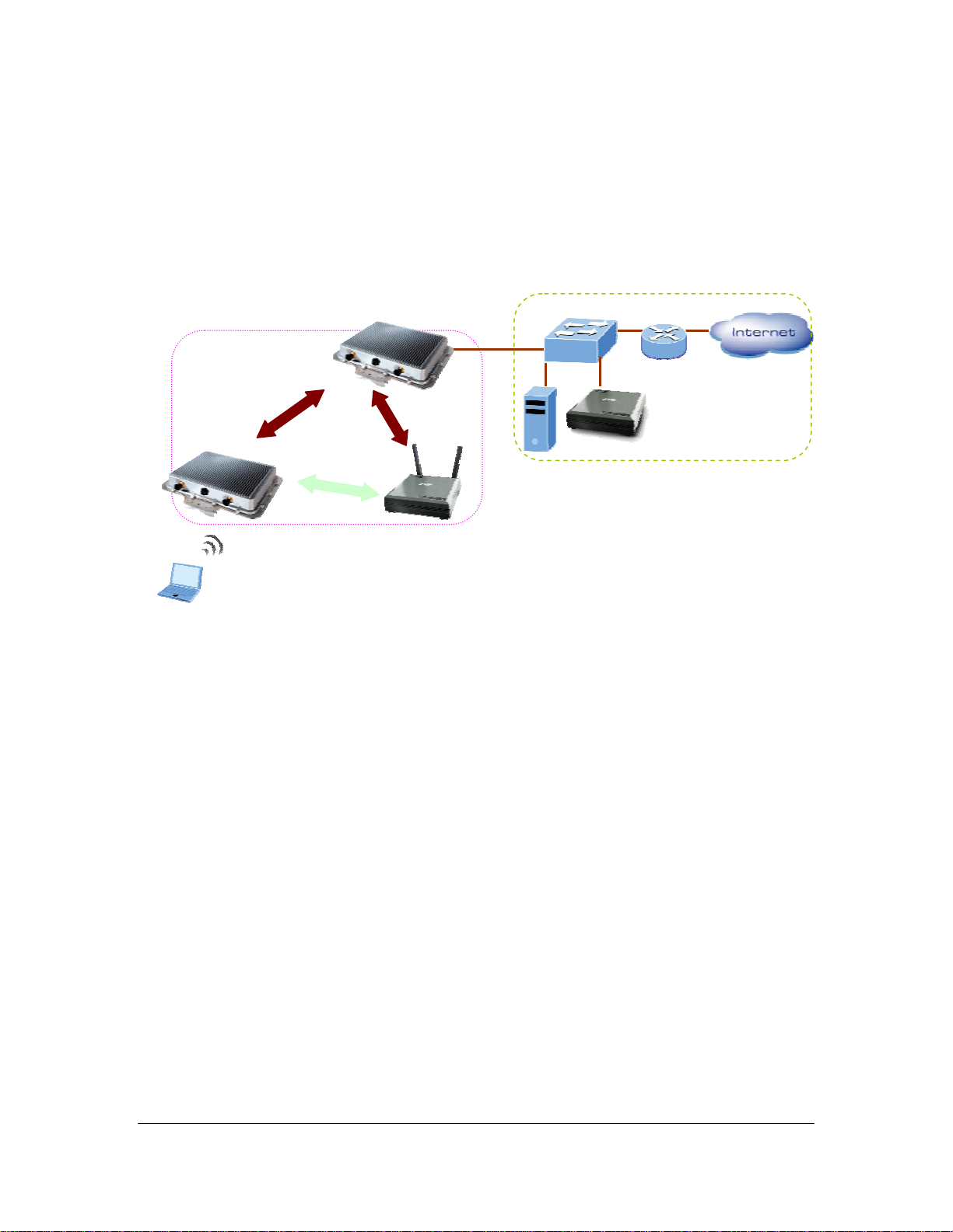
1.3 Network Planning
The basic MESH Network topology can be planned as following.
Mesh Gateway
Mesh Relay
DHCP Server
Mesh Relay
802.11b/g
Mobile User
Ethernet Switch
Router
MAP-2105
1
Page 7
The MAP-2105 should connect to the network that provide DHCP services (the first time
installation) In this guide, we will base on XRT-401D (Internet Broadband Router) as the example
for DHCP server, switch and router, this installation can vary on the network planning.
The MAP-2105 should be installed in the same subnet to the Mesh Gateway for optimal
performance.
The MAP-2105 is optimized for 500-user registration; however, the overall
Note
network performance may vary on the real environment and application in
many aspects, such as the bandwidth to the Internet, the services / sessions
that the clients implement.
1.4 Hardware Installation
1. Using Category 3 or higher UTP or STP cable, connect the WAN port of MAP-2105 to a
10Mbps or 10/100Mbps Ethernet hub or switch, and connect the management station to a
hub or switch on the same LAN.
2. Connect the power adapter to the receptor on MAP-2105 and plug the other end to a wall
outlet or power strip.
ONLY use the power adapter supplied with the MAP-2105. Otherwise, the
Note
product may be damaged.
1.5 Startup the MAP-2105
To get the first management of the MAP-2105, please follow the following steps.
1. Connect the MAP-2105’s WAN port to the network where can provide the DHCP services.
For example, connect to the LAN port of XRT-401D.
2. Power on a PC that also connects to the LAN port of the XRT-401D with DHCP or fixed IP
address.
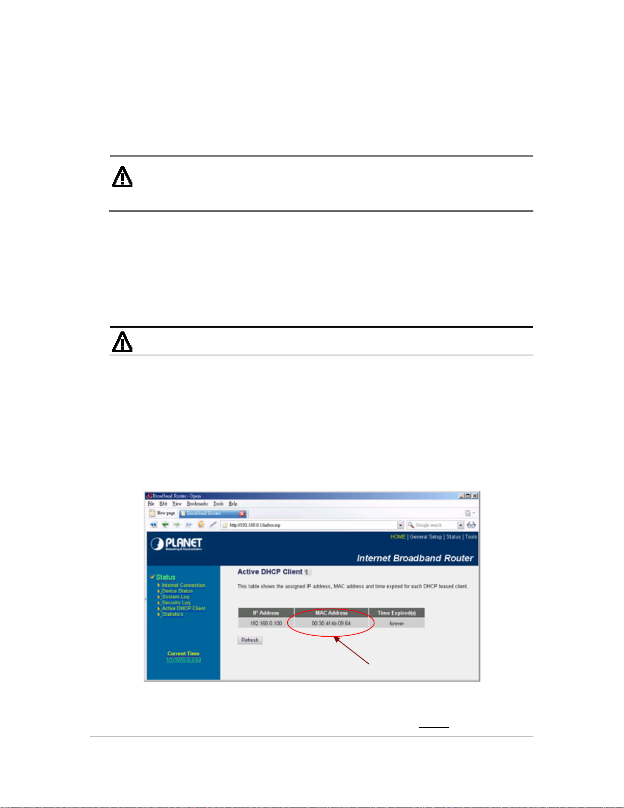
3. Open the Internet browser and go to the DHCP status page of XRT-401D to check the WAN
IP address of the MAP-2105.
WAN MAC Address of
MAP-2105
4. Check the MAC address from the Web page and also the MAC address label of the MAP-
2105. For example, 09-64 as the figure above.
5. Key in the IP address you found for MAP-2105 with “
https://”. For example:
2
Page 8

https://192.168.0.100.
6. The pop-up screen will ask for user name and password. By default, please key in “admin”
for both name and password. Then bring up the screen.
7. Now, the MAP-2105 is ready for services.
3
Page 9
Chapter 2 Basic Network Setup
This chapter describes a basic network environment formed by three mesh AP and one MAP-
2105. The administrators can add the mesh AP freely according to real application.
The sample network topology is as below.
Ethernet Switch
Mesh
Router
Mesh Relay
Mesh Relay
802.11b/g
Mobile User
Step 1: Gateway Configuration:
[Configuration -> Local Service -> VPN Server]
Enable VPN Server = checked
Add New User by pressing Add button
Username: test (it is defined by user)
Password: test (it is defined by user)
Assign IP: 10.16.1.7 (this address must be in the same IP segment as Gateway’s
Backhaul radio IP)
Comment: Testing (it is defined by user)
Status: Enable
MAP-2105
DHCP Server
4
Page 10
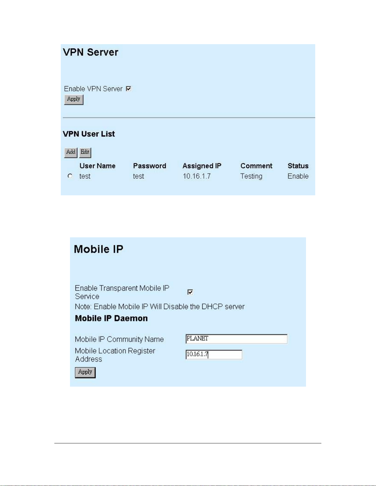
[Configuration -> Local Service -> Mobile IP]
Enable Transparent Mobile IP Service: checked
Mobile IP Community Name: PLANET (it must be identical for all nodes in the same
mesh network)
Mobile Location Register Address: 10.16.1.7 (the IP address assigned in VPN Server
screen)
Step 2: Reboot the Gateway
Step 3: Relay Configuration:
[Configuration -> Local Service -> Mobile IP]
Enable Transparent Mobile IP Service: checked
5
Page 11
Mobile IP Community Name: PLANET (it must be identical for all nodes in the same
mesh network)
Mobile Location Register Address: 10.16.1.7 (the IP address assigned in Gateway VPN
Server screen)
Step 4: Reboot the Relay
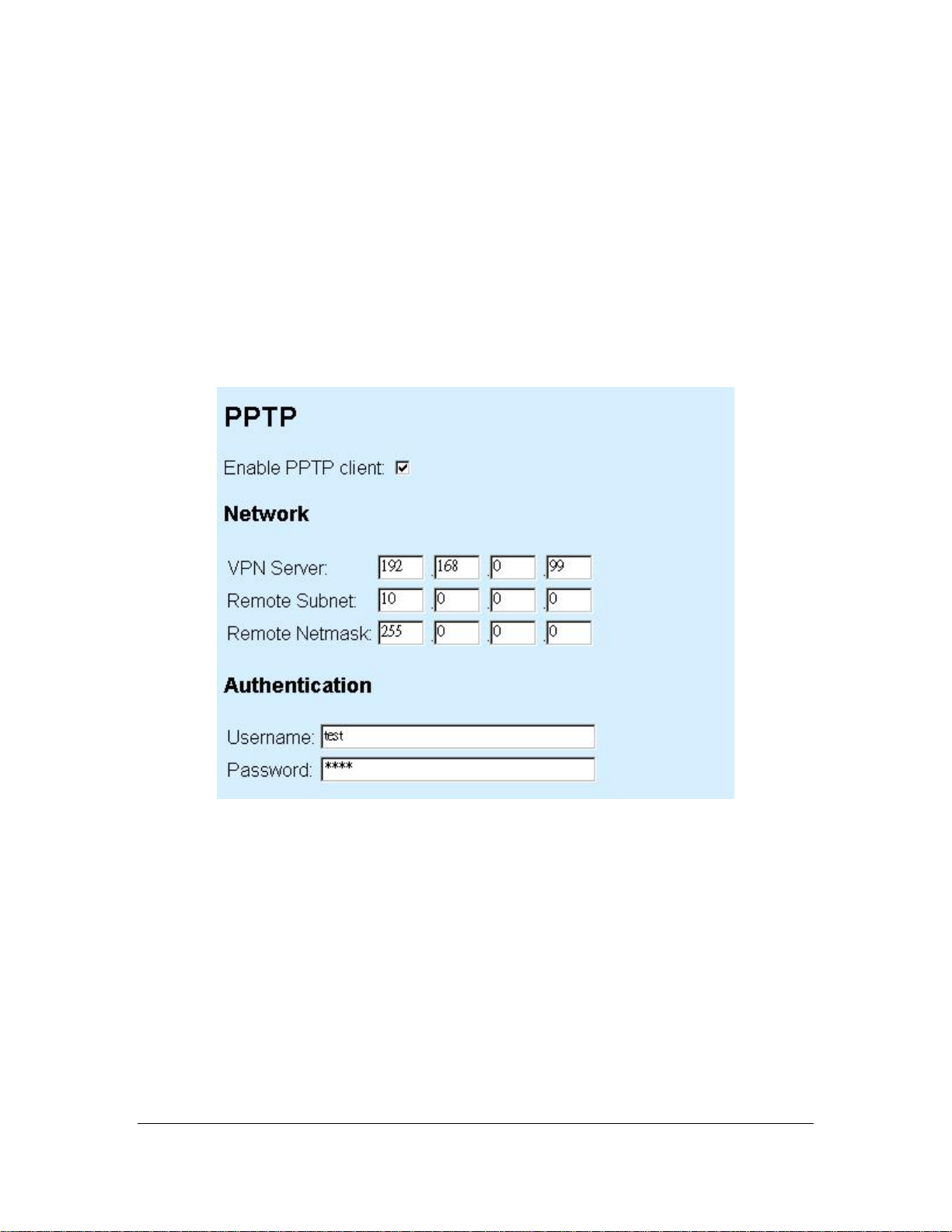
Step 5: MAP-2105 Configuration:
[Configuration -> Local Service -> VPN Client]
Enable PPTP Client: checked
VPN Server: 192.168.0.99 (the Gateway WAN IP address)
Remote Subnet: 10.0.0.0 (the subnet of Gateway’s Backhaul radio IP)
Remote Netmask: 255.0.0.0 (the net mask of Gateway’s Backhaul radio IP)
Username: test (it is identical as defined in Gateway VPN Server screen)
Password: test (it is identical as defined in Gateway VPN Server screen)
Step 6: Reboot the MAP-2105
Step 7: Check MAP-2105 status
6
Page 12
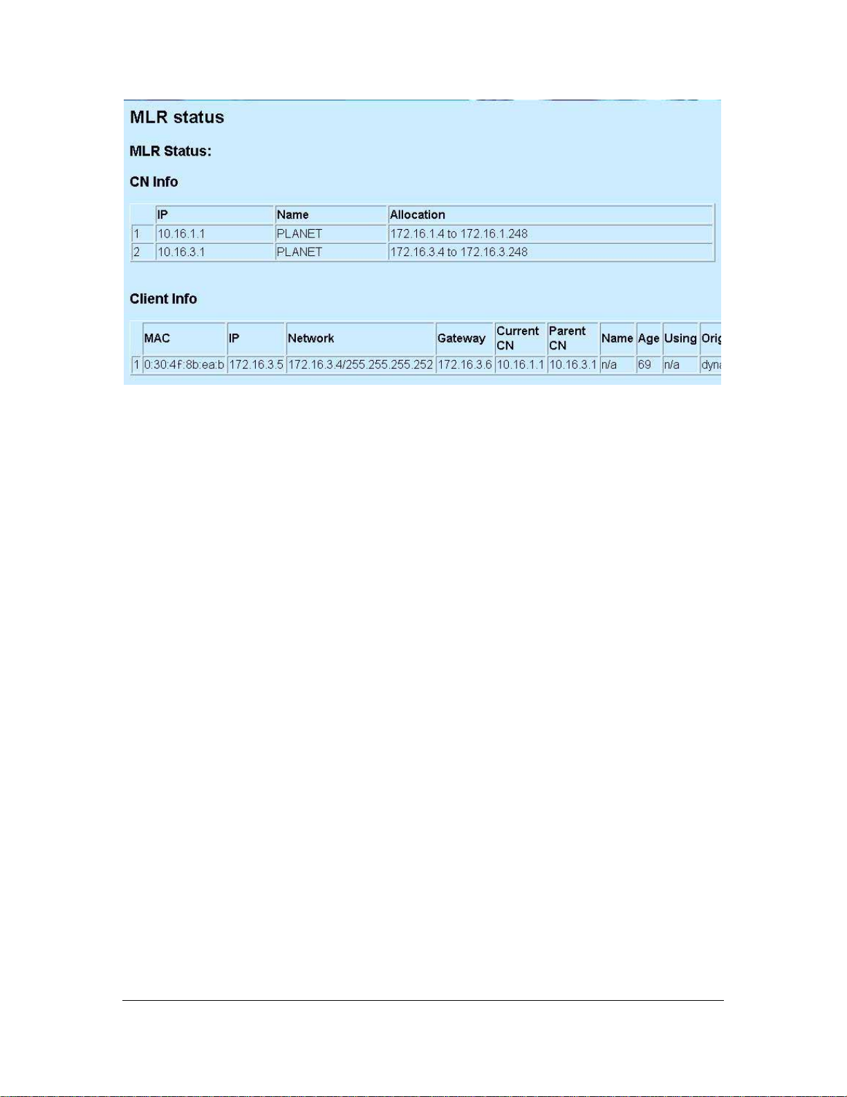
CN Info
Two correspondent nodes connected with relevant info.
Client Info
Info of the mobile station recorded in the MAP-2105.
7
Page 13

Chapter 3 Web Configuration
To start the web configuration,
1. Start the web browser
2. Enter https://IP Address of the MAP-2105, in the address box (make sure HTTPS, but not
HTTP)
3. Accept the security certificate and click ‘Yes’ to proceed.
4. The Web-based configuration login page opens after the security certification has been
accepted.
5. Enter the user name and password. By default, the user name and password are both set to
‘admin’.
8
Page 14
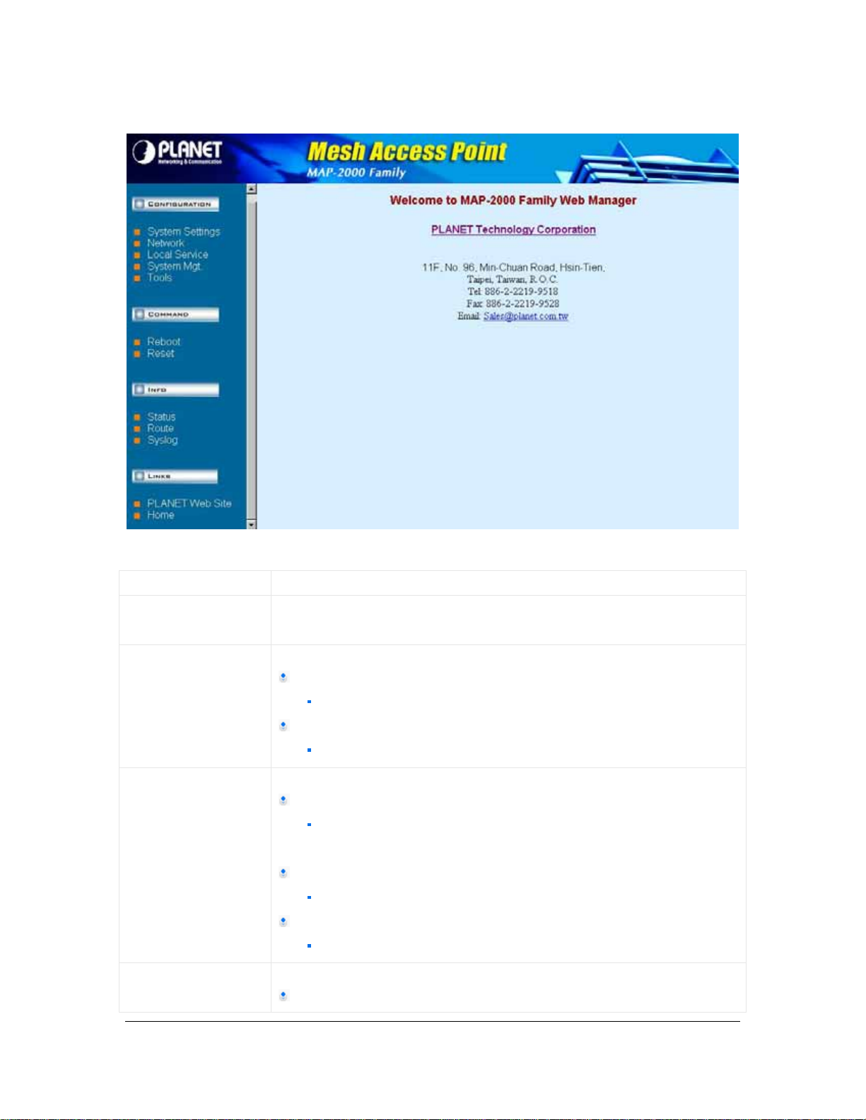
6. After login successfully, the Web-based configuration main page is open, which is appeale d
as below.
The following table describes the navigation button in brief.
Link Description
System Settings Display the system setting s page, which consists of general information
about the system
Network Display or hide the links to WAN and Route.
WAN
contains the configuration for network
Route contains the configuration
contains the configuration for static routing
Local Service Display or hide the links to MLRD, VPN Client, and NTP.
MLRD
contains the configuration for Mobile Location Register Daemon
(Mobile IP)
VPN Client
contains the configuration for Virtual Private Network tunnel
NTP
contains the configuration for Network Time Protocol
System Mgmt Display or hide the links to Password, SNMP, and Syslog Server
Password
9
Page 15

contains the configuration to updates password for web
management server
SNMP
contains the configuration for Simple Network Management
Protocol
Syslog Server
contains the configuration for syslog server
Tools Display or hide the links to Ping, Download, Firmware Update, and
Settings
Ping
ping tools for network diagnostic
Download
contains configuration for TFTP file transfer
Firmware Update
web management firmware management
Settings
contains the configuration for web management server settings
Reboot Display the reboot page, which reboots the system from web
management
Reset Display the reset page, which reverts the settings back to factory default
Status Display or hide the links to System, Interfaces, and Services
System
Display information about system uptime, hardware, memory,
and firmware version.
Interfaces
Display information about interfaces on board
Services
Display information about services running on the system
MLRD
Display information about the MLRD services
Route Output the route information to be displayed on web page
Syslog Output the system message log to be displayed on web page
Vendor Web Site Links to vendor’s web site
Home Links to web management default page
3.1 System Settings
10
Page 16
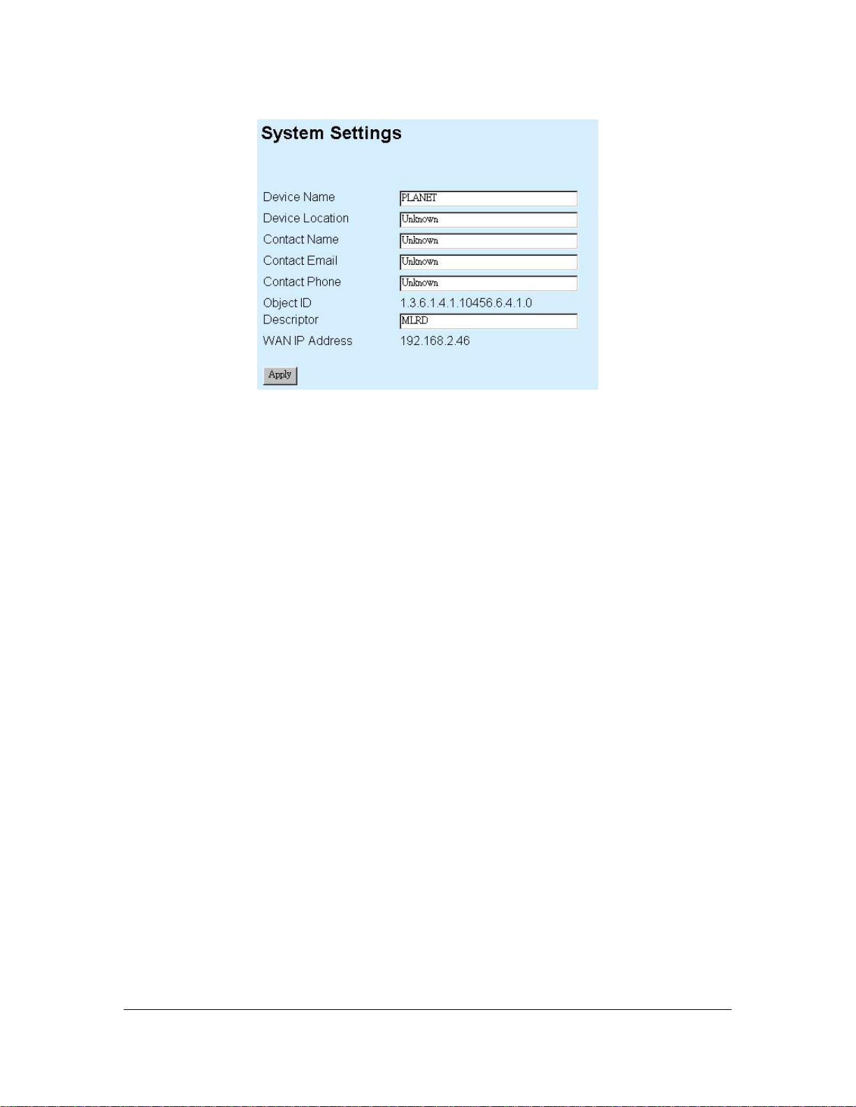
System Settings contains the following:
Device Name
Enter a name for the device.
Device Location
Enter a location that the device is located.
Contact Name
Enter a name for the person to be contacted when consultant is needed regarding to the
device.
Contact Email
Enter an email address to be contacted when consultant is needed.
Contact Phone
Enter a phone number to be contacted when consultant is needed.
Object ID
Display the object identification (OID) of Simple Network Management Protocol.
Descriptor
Add more description about this device.
WAN IP Address
11
Page 17
Display the IP address of the WAN interface of this device. For the first time operation, it
display IP obtained from DHCP server.
“Apply” Button
Submit the changes. New settings are active after the device reboot.
3.2 Network
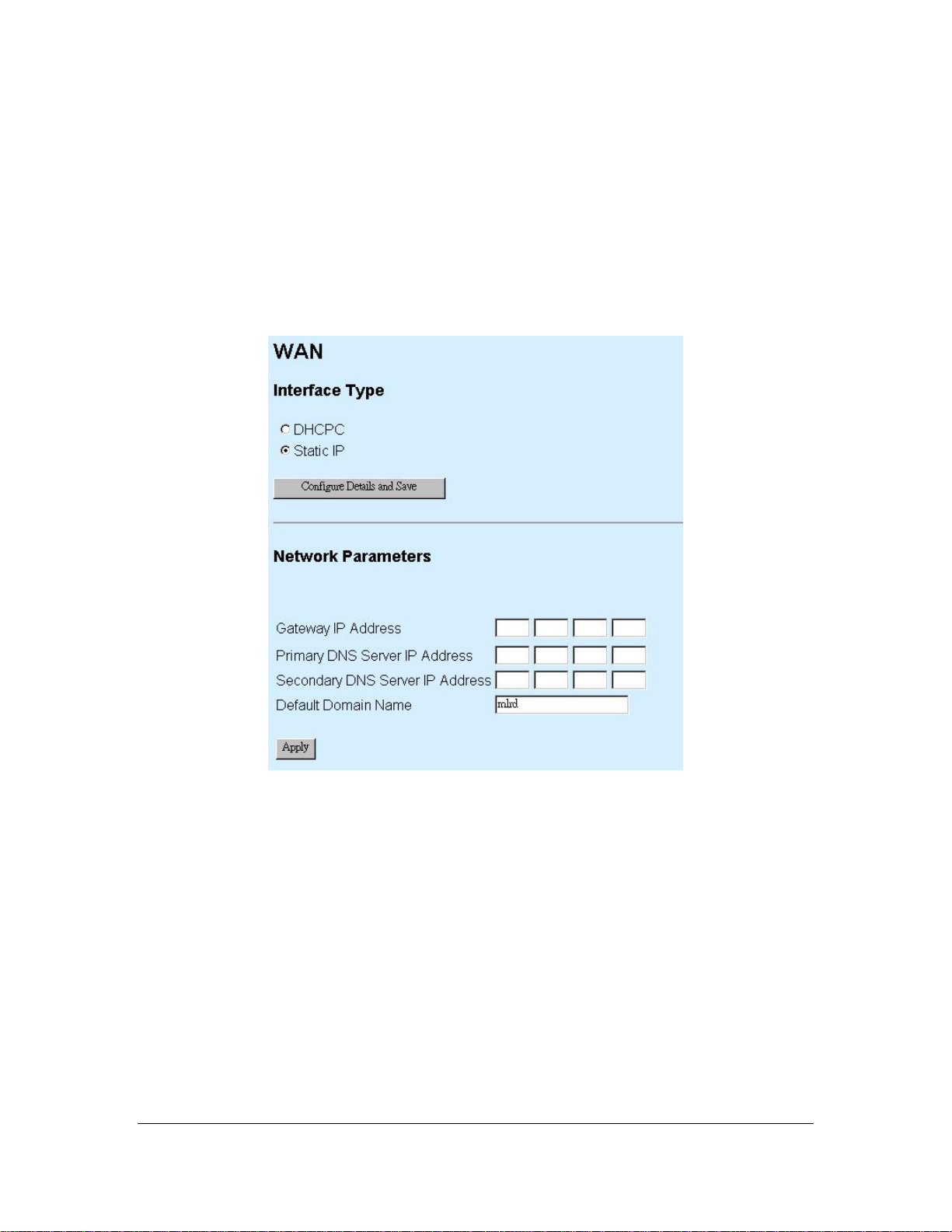
3.2.1 WAN
DHCPC
Dynamically assigns an IP to this device.
Static IP
Specify an IP address to this device. Please complete the network parameters portion.
Configure Details and Save
This button will lead to page according to the selected Interface Type mentioned above.
Pages invoked using “Configure Details and Save” Button are as follow:
-- DHCPC selected
12
Page 18

-- Static IP selected
Please enter the required field as follow:
IP
Enter an IP address for this device
Netmask
Enter a network mask for this IP
Apply
Press this button to save new settings.
Back
Back to previous page
Gateway IP Address
Specify the gateway IP address for this device. Leave blank when DHCPC is enabled,
otherwise this entry will override the information obtained from DHCP server.
Primary DNS Server IP Address
Specify the IP address of the primary DNS server for this device. Leave blank when
DHCPC is enabled, otherwise this entry will override the information obtained from DHCP
server.
13
Page 19
Secondary DNS Server IP Address
Specify the IP address of the Secondary DNS server for this device. Leave blank when
DHCPC is enabled, otherwise this entry will override the information obtained from DHCP
server.
Domain Name
Specify the domain name.
Apply
Press this button to save new settings for Gateway IP Address, Primary and Secondary
DNS Server IP Address, and Domain Name.
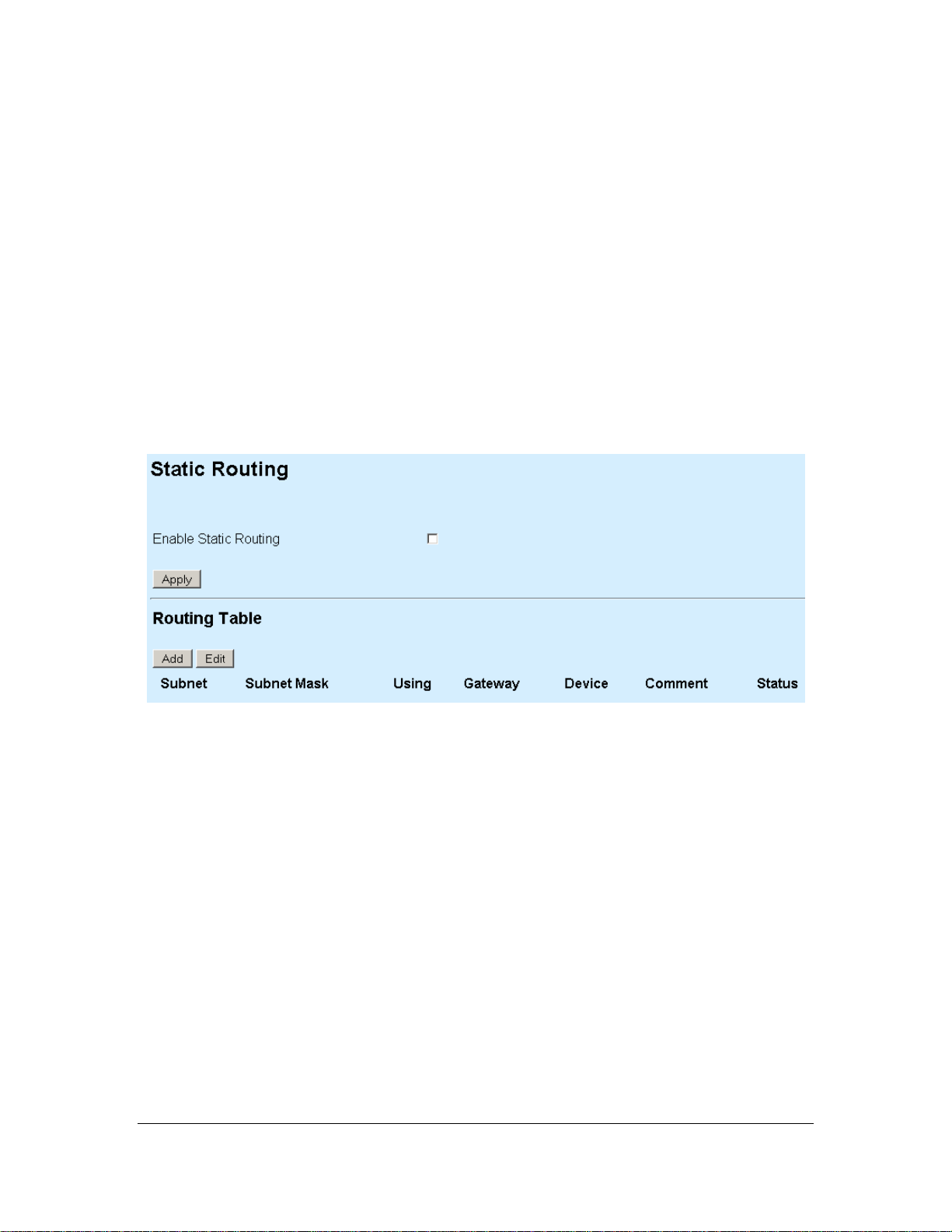
3.2.2 Route
Route contains the following:
Enable Static Routing
Check or uncheck the box to enable or disable static routing for this device.
“Apply” Button
Press this button to apply changes on Enable Static Routing.
Routing Table
Display the current active entry for this device.
“Add” Button
Press this button to add new entry to static routing. The following figure shows the page
invoked after using “Add” Button
14
Page 20
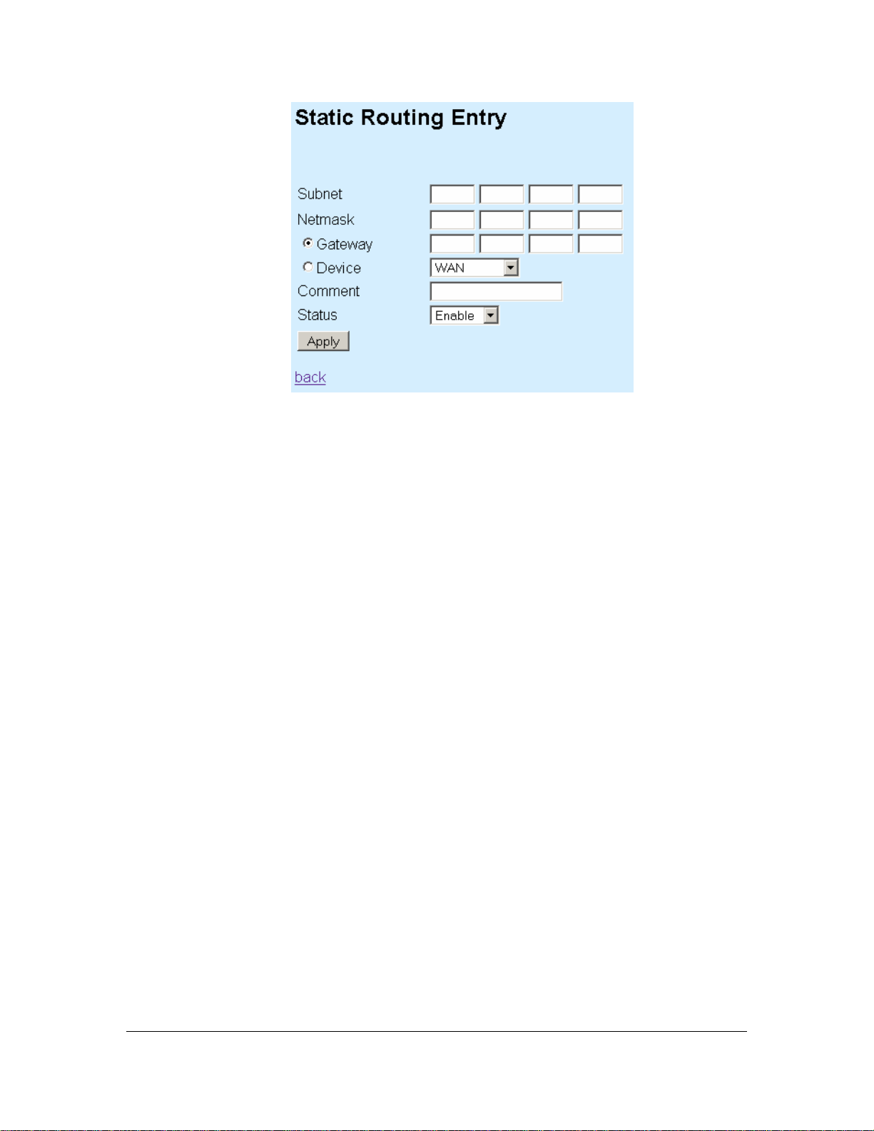
Static Routing Entry contains the following parameters:
Subnet
Enter a subnet IP address.
Netmask
Enter a netmask of the subnet IP address above.
Gateway
Select either gateway or device so that the traffic is through this selection. Please
enter IP address for gateway selection.
Device
Select either WAN or VPN from the drop down list. All the traffic from the
specified subnet will be routed to this selected device.
Comment
Optional comment can be added into this field.
Status
Choose enable to activate this entry, disable to deactivate this entry.
“Apply” button
Press this button to save the settings.
back
Link back to previous page.
“Edit” Button
Press this button to edit the selected entry under the Routing Table. A page similar to “Static
Routing Entry” will be presented. However, it provides one extra button which is the “Delete”
button. Use this button to delete the selected entry.
15
Page 21

3.3 Local Service
3.3.1 MLRD
Mobile Location Register contains the following parameters:
Enable Mobile Location Register Service
Enable or disable mobile location register service.
Mobile IP Community Name
Enter a common name for this entry. Mobile node’s community name must be same for
all participating mobile IP node.
Enable Backup Mobile Location Register
Enable or disable the backup mechanism to another server.
This Mobile Location Register is
Select primary if this server is the main Mobile Location Register server. Select
secondary if this server is configured as a backup server.
Peer MLR Address
Specify the IP address of the backup server for Mobile Location Register.
Backup Interval
Specify the backup interval from main to backup server.
“Apply” button
Press this button to save the new settings.
16
Page 22

3.3.2 VPN Client
VPN contains the following parameters:
Status
Display the status of the VPN client.
Enable PPTP client
Enable or disable PPTP client.
VPN Server
Enter the IP address of the VPN server.
Username
17
Page 23

Enter the username which is pre-defined in VPN server of MESH Gateway.
Password
Enter the password which is pre-defined in VPN server of MESH Gateway.
Enable server-side authentication
Enable or disable server-side authentication.
Servers Username
Enter the server username for server to authenticate.
Servers Password
Enter the server password for server to authenticate.
“Save Config” button
Press this button to save new settings.
Back
Link to previous page.
3.3.3 NTP
NTP-Client contains the following parameters:
Enable NTP-Client
Enable or disable the NTP client.
Server 1
Enter IP address or hostname for the NTP server.
18
Page 24

Server 2
Enter IP address or hostname for the NTP server.
Server 3
Enter IP address or hostname for the NTP server.
Timezone
Click on the drop-down button and select the desired country.
“Apply” button
Press this button to save new settings
3.4 System Management
3.4.1 Password
Password contains the following parameters:
New Pas swo rd
Enter a new password.
New Password (repeat)
Repeat the password entered above to confirm the changes.
“Apply” button
Press this button to save new settings.
3.4.2 SNMP
19
Page 25

SNMP contains the following parameters:
SNMP version
Select from v1 v2, v3, or both.
SNMPv2
Read only community
Enter the v2 read only community.
20
Page 26

Read/Write community
Enter the v2 read write community.
SNMPv3
Read only username
Enter the v3 read only username.
Read/Write username
Enter the v3 read write username.
Secret password
Enter the password for the username configured above.
Secret passphrase
Enter the passphrase for the username configured above.
Access Control
From WAN interface
Check or uncheck the checkbox to allow or ban access for SNMP configuration purposes
from WAN interface.
From VPN interface
Check or uncheck the checkbox to allow or ban access for SNMP configuration purposes
from VPN interface.
From Network
Check or uncheck the checkbox to allow or ban access for SNMP configuration purposes
from Network specified below.
Subnet
Enter a network address for SNMP configuration purposes.
Netmask
Enter the network mask of the configured network address above.
SNMP Trap
Enable SNMP Trap
21
Page 27

Enable or disable SNMP trap for this device.
Trap Community
Enter the trap server community.
Destination
Enter the IP address of the trap server.
Authentication failures
Check or uncheck the checkbox to enable or disable sending of traps when
authentication failures occur.
“Apply” button
Press this button to save new settings.
3.4.3 Syslog Server
Remote-Syslog contains the following parameters:
Status
Display the current state of the remote-syslog server
Host to send syslog (leave empty to disable)
Enter a hostname or IP address of the syslog server. Leave this field empty if no remote
logging required.
“Save Config” button
Press this button to save new settings.
“Use Default” button
22
Page 28

Press this button to restore default configuration for this page.
3.5 Tools
3.5.1 Ping
Ping contains the following parameters:
Ping
Enter an IP address to ping.
Number of pings
Enter the numbers of ping packets to be send before displaying the result.
“Start” button
Start the ping command.
Output
Display the result of the ping command.
23
Page 29

3.5.2 Download
Download contains the following parameters:
Release Version
Display the revision number of the firmware.
TFTP Information
Server IP Address
Enter the TFTP server IP address.
File Name
Enter the filename of the file located at the TFTP server.
File Type
Please select either “config” or “firmware”.
File Operation
Please select either “upload”, “download”, “download and reboot”. Upload will send the
file from device to TFTP server. Note that only config can be uploaded to the server.
Download will get the file from TFTP server, perform all the needed operation.
Download and reboot will get the file from TFTP server, perform all the needed operation
and reboot automatically.
24
Page 30

“Apply” button
Press this button to save new settings and begin TFTP operation.
3.5.3 Firmware Update
Firmware page contains the following parameters:
“Browse” button
Press this button to browse for firmware.
“Upload” button
Press this button to upload the new firmware. Do not switch off the device, or do any
other configuration settings. Wait for it to finish. Failure in firmware update may cause the
device to be unusable.
25
Page 31

3.5.4 Settings
26
Page 32

Settings contain the following parameters:
Save Config
Click on the “mlrd.cfg” hyperlink to save the current configuration into local computer.
This configuration file can be used for debugging purpose as well as cloning settings to
all other devices.
Restore Config
Select the proper configuration to be restored. Press the “Browse” button to select the
correct file to be restored. After this, Press the “Upload” button to upload the selected file.
This action will override current configuration. Please use with caution.
Install New Webserver Certificate
Select the proper certificate to be uploaded to the internal web server. Failing to do so
may cause the web server to stop running. Always use a tested web server certificate for
this purpose.
Access Control
From WAN Interface
Check or uncheck the checkbox to allow or ban access for configuration purposes from
WAN interface.
From VPN Interface
Check or uncheck the checkbox to allow or ban access for configuration purposes from
VPN interface.
From Network
Check or uncheck the checkbox to allow or ban access for configuration purposes from
Network.
Subnet
Allow this network address for configuration access.
Netmask
Network mask for the subnet configured above.
“Save Config” button
27
Page 33

Press this button to save new settings.
“Use Default” button
Press this button to restore the factory default configuration for this page.
3.6 Reboot
Reboot contains the following parameters:
Please enter the time to reboot (seconds)
Enter a delay value so that the device will only reboot after the requested delay of time.
“Reboot” button
Press this button to reboot the device. If a delay is specified, it will wait for that amount of
time before rebooting the device.
3.7 Reset
Reset contains only one “Reset to Factory Default” button. Press this button to restore the
configuration for the device back to factory default.
3.8 Status
28
Page 34

3.8.1 System
System contains the following parameters:
Uptime
Display the uptime of the device since last booting.
Hardware
Display the state of the hardware.
CPU
Display information about the Central Processing Unit.
Memory
29
Page 35

Display information about the memory state of the device.
Firmware
Display the revision version of the firmware.
3.8.2 Interfaces
Interfaces contain the following parameters
WAN Information
Link to more detail information about the WAN interface. Figure below shows the detail
information of the WAN interface
30
Page 36

Interface
Display the state of the interface. Running means the interface is up and running.
Hardware Address
Display the hardware address of the interface.
IP address
Display the IP address of the interface.
31
Page 37

3.8.3 Services
Services page will display the status of each process and a corresponding “Restart” button to
restart that particular service.
3.8.4 MLRD
MLRD contain the following information
32
Page 38

CN Info
Display the information of connected Correspondent Node.
Client Info
Display the information of client register to the MAP-2105.
3.8.5 Route
Route contains the following parameters:
“Refresh” button
Press this button to refresh the content of the output area.
Output
Display the output of route command.
33
Page 39

3.8.6 Syslog
Syslog contains the following parameters:
“Refresh” button
Press this button to refresh the content of Output area.
Output
Display the output of the syslog command.
34
Page 40

Chapter 4 Management Utility
The PLANET MLRD Management Suite is a Java-based software application designed
specifically to manage the MAP-2105 which act as a server for the mesh nodes with the Mobile IP
feature.
Generally, the MLRD Management Suite is consists of three major sections, the AP-Finder, Trap
Viewer and MLRD Manager. The AP Finder is utilized as a scanner to discover the MAP-2105
within the subnet. Trap Viewer is able to receive and log the alarms sent by the nodes. And the
MLRD Manager is used to configure the nodes through Simple Network Management Proto co l
(SNMP).
4.1 Installation and Un-installation
4.1.1 To install the MLRD Management Suite
To install the MLRD Management Suite on your terminal, grab the MLRD_installer.exe application
file found on the accompanying CD-ROM to any desired directory. Double-click the application file
to start up the installation. After completely extracting, a loading window would show on the
screen, as illustrated:
Once loaded, the installation wizard will be started up. Follow the simple steps directed by the
wizard:
1. Introduction – A brief introduction regarding the installer.
35
Page 41

2. Choose Install Folder – Select the desired directory to locate the software application.
3. Choose Shortcut Folder – Set the shortcut path.
36
Page 42

4. Pre-Installation Summary – A review of the installation settings before starting the
installation.
5. Installing – Display the progress of the installation.
37
Page 43

6. Install Complete – Indicate the installation has been completed.
After complete the steps, you can start up the MLRD Management Suite from the shortcut
created.
4.1.2 To Uninstall the MLRD Management Suite
The MLRD Management Suite Uninstaller wizard is built along with the application. You can
uninstall the application by activate the wizard, namely Uninstall_MLRD Management Suite.exe,
which is located in the program folder. Follow the three simple steps
38
:
Page 44

1. Introduction – About the uninstaller. The un-installation will be started once the Uninstall
button is hit.
2. Uninstalling – The un-installation is in progress. Note that every files and folder created
during the installation will be removed.
3. Uninstall Complete – Un-installation completed successfully.
4.2 How to use MLRD Management Suite
4.2.1 AP Finder
The AP Finder is used to discover the IP Address of the MAP-2105 available in the subnet. The
figure below illustrates the outlook of the AP Finder.
In order to start scanning for the nodes, select the Scan button at the right pane of the AP Finder.
The system will search for the available MAP-2105 and display at the table. Alternatively, user
can start the AP-scan by select the Actions > Scan Start from the menu bar.
On the other hand, the Stop button, or Actions > Scan Stop at the menu bar is used to cancel
the scan.
Check the Auto Rescan option in between the Scan and Stop button to enable the scanning
process restart automatically after sleep for certain period. User can configure this feature via
Settings > Auto-Rescan option from the menu bar as well.
To set the time interval for rescanning, choose Settings > Rescan Interval from the menu bar. A
window will be pop-up to prompt the user to enter the desired duration in seconds, as shown at
the following figure.
39
Page 45

The status bar located at the bottom of the AP Finder is displaying the status of the scanning
process. While the –Select Adapter- drop down list, allow user to choose the adapter to configure
the nodes. Two options are available: MLRD Manager or Web-based Configuration Pag e.
4.2.2 Trap Viewer
The trap viewer is used to catch the alarm or trap send from the MAP-2105, which have their trap
destination IP Address set to the user’s IP Address. In the MLRD Management Suite, user can
switch between the AP Finder and Trap Viewer by selecting the tab at the left bottom corner.
Alternatively, this can be done by choosing View > AP Finder or View > Trap Viewer to toggle
between the pages.
The following figure display the layout of the Trap Viewer.
40
Page 46

In order to start listen to the alarms, hit on the Start button. The foreground of the Start button will
turn to green color when the trap viewer is running. Conversely, select the Stop button to disable
the Trap Viewer, where the foreground of the Stop button changes to red color. The traps
received will be displayed at the table provided.
The table displays the trap’s description, source IP Address, trap severity and the time it is caught.
For more details regarding the trap, select the desired row and click on the info button. A dialog
box will pop-up and display more details of the node, as shown by the following figure.
These traps should be deleted once they are reviewed or resolved. In order to delete the trap
from the table, select the desired row or rows, and click on the Clear button.
By default, every alarm shown in the table will be logged into a file, named Alarm_Default in the
TrapLog folder at the application directory. However, options are available for the users to write
into a different file or even disable the log feature. To change a log file, enter a new file name at
41
Page 47

the Output File Name text box in the Settings column and press the Set button. Besides, choose
Settings > Output Filename from the menu bar would open a window to prompt the user for the
new log file name.
To disable the log feature, uncheck the Write to File check box in the Settings column and hit the
Set button, or uncheck the Settings > Write to File menu item from the menu bar. Under this
circumstance, the alarms deleted from the Trap Viewer will be gone forever.
The remaining two setting option in the Settings column is the Port and Community. The Port
defines the port number of the system to listen to the alarms, while the Community defines the
password to match the community of incoming traps. Similarly, user can fill in the value in the
space provided and hit the Set button or select from the menu bar.
4.2.3 MLRD Manager
The MLRD Manager is the configuration pages of a MAP-2105. User may open the MLRD
Manager to update or edit the settings of the node. In order to start up the MLRD Manager,
choose the MLRD Manager from the drop-down list at the left bottom corner of AP-Finder, as
shown:
This action will open window to prompt the user for the SNMP Passwords. The configurations can
only be done with the correct password or community. Note that the MLRD Manager is supporting
SNMP Version 1, 2c and 3. Thus for SNMP Version 1 or 2c, only the Community field is
compulsory, whereas for SNMP Version 3, the Username, Password and Pass Phrase fields is
required to be filled.
42
Page 48

The upcoming section is going to describe regarding the configuration of the MAP-2105 via
MLRD Manager.
43
Page 49

4.3 Node Configuration using MLRD Manager
The MLRD Manager is a Java-based graphical interface application that allow user to perform
configuration of the specific MAP-2105. The configurations are done via Small Network
Management Protocol (SNMP). Besides, it also supports some action commands, for instance
download/upload, reboot and reset the factory settings for the particular node
As overall, the MLRD Manager consists of 5 submenus: File, Status, Config, Command and Help.
4.3.1 File >Change SNMP Password
This option allows user to change the SNMP Password in case when the user desire to change
the password from read-only password to read-write password, or change the SNMP Version.
The Change Community window consists of the following parameters:
IP Address
44
Page 50

This read-only field shows the IP Address of the current MAP-2105.
SNMP Version
The Version of SNMP using to read and write data from/to the node. Two options are
available: 1 or 2C and 3.
Community
The community of the SNMP. If the Version 1 or 2C is selected as the SNMP Version,
this field is required.
User Name
The admin user name that given permission to perform the SNMP action.
Password
The authentication password. The default authentication method used is MD5.
Pass Phrase
The privacy pass phrase that must be more than 8 characters
4.3.2 Status > System
This submenu is basically a read-only page, provides user a brief summary regarding the MAP-
2105. In order to configure the fields in this frame please refer to Configuring System Settings at
the coming section.
The parameters at the System page:
Node Name
A name for the MAP-2105.
Node Location
A location description of the MAP-2105.
45
Page 51

Status
The node operation mode, which can be Online or Offline
Contact Name
A generic name of the network administrator.
Contact Email
A generic E-mail Address of the network administrator.
Contact Phone
A generic phone number of the network administrator.
Object ID
The Object ID (OID) of the MLR Node specified to support the SNMP service.
Up Time
A real-time field that displaying the period of the node since it is turned on.
4.3.3 Status > MLRD
This panel contains two tables, CN Info table and Client Info table, respectively. CN is the
abbreviation of Correspond Node, where the table displaying the information regarding the MAP-
2105. The information shown at this table:
- IP Address,
- Name,
- IP Allocation of the nodes.
Whereas the Client Info table shows the information regarding the client nodes, which is operate
under the MAP-2105. The information displayed are:
- MAC Address,
- IP Address,
- Previous CN IP Address,
- Current CN IP Address
The refresh button,
table entries.
, at the right top corner of the table is used to refresh and update both the
46
Page 52

4.3.4 Config > System
System panel is used to configure the System settings such as the administrator name and
contact information, as mentioned at the View System Status.
Descriptor
A short description regarding this managed device.
47
Page 53

4.3.5 Config > Network > WAN
This panel consists of two parts: the upper part allow user to select the WAN Interface type to use
and the lower part is used to configure the network settings. In order to select a WAN Interface,
select on the desired type and type the Configure Details button.
Note: the MAP-2105 does not support PPPoE connection type.
The network setting portion enables the configurations on the DNS (Domain Name Service). This
feature translates the domain name into IP Address form, which recognized by the Internet. This
translation is done through its own server. If the primary server failed to perform the translation,
the secondary server will take over the process.
The parameters of the Network panel:
Gateway
Specify the gateway for the static IP Address
48
Page 54

Primary DNS Server IP Address
Specify the IP Address of the primary DNS Server for this device
Secondary DNS Server IP Address
Specify the IP Address of the secondary DNS server for this device
DNS Domain Name
Specify an optional domain name for the DNS client
Choose the desired Interface Type and hit the Configure Details button will lead to the
configuration page for the specific interface type.
Config > Network > WAN > Static
Status
This is a read-only field that displays the status of the Static WAN IP Configuration. The
Static WAN IP will be disabled if the DHCP-Client type is selected.
IP Address
The IP Address of the Static WAN IP Address
Netmask
The net mask corresponding to the Static WAN IP Address
Click on the Save and Enabled Static IP button to enable this type.
Config > Network > WAN > DHCP-Client
49
Page 55

Status
Display the status of the DHCP-Client type. This field is read-only and will be disabled if
the Static WAN IP is selected.
Click on the Enable DHCP-Client button to enable this Interface Type.
50
Page 56

4.3.6 Config > Network > Route
This section describes about the parameters for the Route table.
Enable Route Table
Check this checkbox to enable the use of Route Table
Route Table
Displaying the current active entry in this device.
Config > Network > Route > Route Table
51
Page 57

This table consists of seven columns:
Subnet
Specifies the Subnet IP Address of the route
Netmask
Specifies the Netmask corresponding to the Subnet IP Address of the route
Gateway
Specifies the gateway IP Address for this route
Device
Specifies the route devices for this route. Two options are available: WAN and VPN
Gateway/Device
Specifies whether the entry is using the Gateway or Device option
Status
Specifies the status of this entry, which can be Enable or Disable
In order to add a new entry to the Route Table, fill in the parameters required at the bottom of the
table, and click the Add button. On the other hand, if user wishes to edit the value or delete the
existing entry in the table, select the desired row and click Edit and Delete button, respectively.
52
Page 58

4.3.7 Config > Management > SNMP Password
This panel is basically separate to three different sections. The upper panel is used to change or
reset the SNMP v1, v2c and v3 passwords. User can edit the password by entering the new
password in the corresponding space, retype in the confirm space, and click on the Change
button
The parameters at this section
Read-Only Community
Read-Write Community
Read-Only Username
Read-Write Username
Password
53
Page 59

Pass Phrase
The middle panel is to configure the Access control of the SNMP. Click the Set Access Config
button to load the settings.
The parameters at this section
From WAN Interface
Check the checkbox to allowed the access from WAN device to SNMP
From VPN Interface
Check the checkbox to allowed the access from VPN device to SNMP
From Network Interface
Check the checkbox to allowed network to access the SNMP
Subnet
The Subnet IP Address of the allowed network. This field is disabled if From Network
Interface is disabled
Netmask
The Netmask, corresponding to the Subnet IP Address, of the allowed network
The bottom panel allowed user to configure details regarding the SNMP Trap. Click on the Set
Trap Configurations button to enable the settings.
The parameters at this section
Enable SNMP Trap
Check this option to enable the use of SNMP Traps
SNMP Trap Version
Specifies the SNMP version used for the SNMP Trap. Three options are available: SNMP
v1 or v2c, SNMP v3, and both
Destination IP Address
Specifies the destination IP Address to send the trap message to. Fill in the IP Address of
the Trap Viewer will enable the Trap Viewer to capture the trap release by this node
54
Page 60

Community
Specifies the secret password refer to the SNMP Trap.
Enable Trap Authentication
Check the checkbox to enable the sending of trap when authentication failure occurs
4.3.8 Config > Management > Access Control
User is able to configure the access control of the web-based configuration page at this panel.
The parameters at this section
From WAN Interface
Check the checkbox to allowed the access from WAN device to web-configuration
From VPN Interface
Check the checkbox to allowed the access from VPN device to web-configuration
From Network Interface
Check the checkbox to allow specified network to access the web-configuration
Subnet
The Subnet IP Address of the allowed network. This field is disabled if From Network
Interface is disabled
Netmask
The Netmask, corresponding to the Subnet IP Address, of the allowed network
55
Page 61

4.3.9 Config > Management > Remote Syslog
This submenu is used to set the remote syslog server IP Address, who is receiving the syslog
message from the MAP-2105.
Remote Server
Specifies the IP Address of the syslog server at the column provided. In order to disable
this feature, please leave the column empty and click the OK button
4.3.10 Config > Services > NTP-Client
The NTP is a protocol that used to synchronize the clocks of computers to some time reference.
In this case it is used to synchronize the time of different nodes
Parameters at this page:
Enable NTP-Client
Enable of disable the NTP-client feature
56
Page 62

Server 1, Server 2, Server 3
The network will connect to the NTP server 1, while Server 2 and 3 are used as back up
servers.
Time Zone
Choose the desired time zone from the list available
4.3.11 Config > Services > Mobile IP
This section describes the parameters of the MLRD. The parameters at this panel:
Enable Mobile Location Register Service
Check the checkbox to enable the mobile location register (MLR) service
Mobile IP Community Name
Specify a common name, which is compulsory for all the participating mobile IP nodes
Enable Backup Mobile Location Register
Check the checkbox to enable the information backup to another server
MLR Type
57
Page 63

Select the type of MLR. The available choices are Primary and Secondary. Select
Primary if this server is the main MLRD, and secondary if it is configured as a backup
server
Peer MLR Addrss
Specifies the IP Address of the backup server for MLR
Backup Interval
Specifies the time interval to wait, in seconds, before change from main to backup server
4.3.12 Config > Services > VPN-Client
This section describes the parameters in the VPN-Client Panel
The available parameters:
Enable PPTP-Client
Check the given checkbox to enable the PPTP service
58
Page 64

VPN Server
Enter the IP Address of the VPN Server
Remote Network Subnet
The Subnet IP Address of the Remote Network
Remote Network Netmask
The Netmask, corresponding to the subnet IP Address of the Remote Network
Authentication Username
Specifies the username to authenticate to the server
Authentication Password
Specifies the password corresponding to the username to authenticate to the server
Enable server-side Authentication
Check the given checkbox to enable the server-side authentication
Server username
Specifies the username for the server-side authentication. This field is disabled when
Enable server-side Authentication is disabled
Server password
Specifies the password for the server-side authentication. This field is disabled when
Enable server-side Authentication is disabled
59
Page 65

4.3.13 Commnad > Download/Upload
The MAP-2105 also provides the download and upload file feature. The following section
describes the parameters of this pane
Server IP Address
Specifies the TFTP Server IP Address
File Name
Specifies the file name to be downloaded or uploaded
File Type
Select the file Type. The available options are Config file and Firmware image
Operation Type
Choose the type of operation to perform:
- Upload
- Download
- Download and Reboot
After enter the parameters, click on the OK button to start performing the command.
4.3.14 Command > Reboot
After configure the settings using MLRD Manager, the MAP-2105 must be rebooted before the
settings take effect. However, beware that the reboot process would cause all the user who are
currently connected to the network lose their connection until the unit has completely restart-up
and resume.
60
Page 66

Time to Reboot
Specifies the time to delay before the reboot take place, in seconds. Click the Reboot
button to execute the command.
4.3.15 Command > Reset
Through this submenu, user may set the MAP-2105 back to its default factory settings. However
performing the reset would cause all the settings done previously lost permanently
Click the Reset to Factory Default button to execute the command.
4.3.16 Help > About
This option display the version of the MLRD Manager
61
 Loading...