

Page 1

IP DSLAM Switch
IDL-2402
User's Manual
- 1 -
Page 2

Copyright
Copyright (C) 2008 PLANET Technology Corp. All rights reserved.
The products and programs described in this User’s Manual are licensed products of PLANET
Technology, This User’s Manual contains proprietary information protected by copyright, and this
User’s Manual and all accompanying hardware, software, and documentation are copyrighted.
No part of this User’s Manual may be copied, photocopied, reproduced, translated, or reduced to
any electronic medium or machine-readable form by any means by electronic or mechanical.
Including photocopying, recording, or information storage and retrieval systems, for any purpose
other than the purchaser's personal use, and without the prior express written permission of
PLANET Technology .
Disclaimer
PLANET Technology does not warrant that the hardware will work properly in all environments
and applications, and makes no warranty and representation, either implied or expressed, with
respect to the quality, performance, merchantability, or fitness for a particular purpose.
PLANET has made every effort to ensure that this User’s Manual is accurate; PLANET disclaims
liability for any inaccuracies or omissions that may have occurred.
Information in this User’s Manual is subject to change without notice and does not represent a
commitment on the part of PLANET. PLANET assumes no responsibility for any inaccuracies that
may be contained in this User’s Manual. PLANET makes no commitment to update or keep
current the information in this User’s Manual, and reserves the right to make improvements to this
User’s Manual and/or to the products described in this User’s Manual, at any time without notice.
If you find information in this manual that is incorrect, misleading, or incomplete, we would
appreciate your comments and suggestions.
FCC Warning
This equipment has been tested and found to comply with the limits for a Class A digital device,
pursuant to Part 15 of the FCC Rules. These limits are designed to provide reasonable protection
against harmful interference when the equipment is operated in a commercial environment. This
equipment generates, uses, and can radiate radio frequency energy and, if not installed and used
in accordance with the Instruction manual, may cause harmful interference to radio
communications. Operation of this equipment in a residential area is likely to cause harmful
interference in which case the user will be required to correct the interference at his own
expense.
FCC Caution
To assure continued compliance (example-use only shielded interface cables when connecting to
computer or peripheral devices). Any changes or modifications not expressly approved by the
party responsible for compliance could void the user’s authority to operate the equipment.
This device complies with Part 15 of the FCC Rules. Operation is subject to the Following two
conditions: (1) This device may not cause harmful interference, and (2) this Device must accept
any interference received, including interference that may cause undesired operation.
CE mark Warning
The is a class A device, In a domestic environment, this product may cause radio interference, in
which case the user may be required to take adequate measures.
- 2 -
Page 3

Trademarks
The PLANET logo is a trademark of PLANET Technology. This documentation may refer to
numerous hardware and software products by their trade names. In most, if not all cases, these
designations are claimed as trademarks or registered trademarks by their respective companies.
WEEE Warning
To avoid the potential effects on the environment and human health as a result of
the presence of hazardous substances in electrical and electronic equipment,
end users of electrical and electronic equipment should understand the meaning
of the crossed-out wheeled bin symbol. Do not dispose of WEEE as unsorted
municipal waste and have to collect such WEEE separately.
Safety
This equipment is designed with the utmost care for the safety of those who install and use it.
However, special attention must be paid to the dangers of electric shock and static electricity
when working with electrical equipment. All guidelines of this and of the computer manufacture
must therefore be allowed at all times to ensure the safe use of the equipment.
Revision
User’s Manual for PLANET IP DSLAM
Model: IDL-2402
Rev: 1.0 (Oct. 2008)
Part No.: EM-IDL2402_v1
- 3 -
Page 4

Table of Contents
1. Introduction............................................................................................................. 16
1.1 Product Features ............................................................................................. 16
1.2 Package Contents............................................................................................ 17
1.3 Application ....................................................................................................... 18
1.4 Outlook............................................................................................................. 19
1.4.1 Front Panel ............................................................................................ 19
1.5 Technical Specifications ................................................................................. 20
2. Installation............................................................................................................... 22
2.1 Safety Instruction ............................................................................................ 22
2.2 Hardware Installation....................................................................................... 23
2.2.1 System Requirements............................................................................ 23
2.2.2 Installation Procedure............................................................................ 23
2.3 WEB Configuration..........................................................................................27
2.3.1 System Prepartion ................................................................................. 27
2.3.2 WEB Configuration Procedure............................................................... 27
2.3.3 How to backup / Restore the Configuration ........................................... 32
2.3.4 Firmware Update ................................................................................... 42
3. Software Introduction............................................................................................. 45
3.1 General Overview ............................................................................................ 45
3.1.1 Features of Management Interface........................................................ 46
3.2 Configuration Management ............................................................................ 47
3.2.1 Bridge Configuration.............................................................................. 48
3.2.2 ADSL Configuration................................................................................ 49
3.3 Performance management.............................................................................. 50
3.3.1 RMON Feature....................................................................................... 52
3.4 Fault Management ........................................................................................... 54
3.5 Loopback Testing ............................................................................................ 56
3.6 Cluster Feature ................................................................................................ 57
4. WEB Management................................................................................................... 58
4.1 System.............................................................................................................. 62
4.1.1 System Information................................................................................ 62
4.1.2 Board IP Setup....................................................................................... 63
4.1.3 Ethernet Port Service.............................................................................64
4.1.4 ADSL Port Service ................................................................................. 65
4.1.5 CLI Setup............................................................................................... 67
4.1.6 Cluster Setup......................................................................................... 68
4.1.7 System Inventory................................................................................... 71
4.1.8 System Contact Info............................................................................... 72
4.1.9 SNTP..................................................................................................... 73
4.1.10 IP Routes............................................................................................. 74
4.1.11 User Administration.............................................................................. 75
4.1.12 Duplicator............................................................................................. 77
4.2 802.1x Security................................................................................................. 78
4.2.1 System Protocol.....................................................................................78
4.2.2 RADIUS &Local Profile.......................................................................... 82
4.3 Bridge ............................................................................................................... 84
4.3.1 Interface Setup....................................................................................... 84
- 4 -
Page 5

4.3.2 VLAN Configuration............................................................................... 92
4.3.3 Access Control..................................................................................... 100
4.3.4 Forwarding........................................................................................... 127
4.3.5 Relay.................................................................................................... 129
4.3.6 IGMP.................................................................................................... 131
4.3.7 IPOA.................................................................................................... 138
4.4 ADSL............................................................................................................... 141
4.4.1 Profile................................................................................................... 141
4.4.2 Data & Inventory.................................................................................. 153
4.4.3 Line Config & Info ................................................................................ 162
4.5 Traffic.............................................................................................................. 165
4.5.1 A TM Traffic Descriptor.......................................................................... 165
4.6 SNMP .............................................................................................................. 168
4.6.1 SNMP Community ............................................................................... 168
4.6.2 SNMP Target........................................................................................ 169
4.6.3 SNMP Notify ........................................................................................ 171
4.7 Maintenance................................................................................................... 172
4.7.1 SYS Log Server................................................................................... 172
4.7.2 Database ............................................................................................. 173
4.7.3 Firmware Update ................................................................................. 180
4.7.4 A TM Loopbacks ................................................................................... 183
4.7.5 Fault Management............................................................................... 184
4.7.6 Performance Monitoring....................................................................... 189
5. CLI Command Reference...................................................................................... 206
5.1 Global Commands......................................................................................... 212
5.1.1 bye....................................................................................................... 212
5.1.2 cluster.................................................................................................. 212
5.1.3 cluster local.......................................................................................... 212
5.1.4 disable ................................................................................................. 212
5.1.5 end....................................................................................................... 212
5.1.6 exit....................................................................................................... 212
5.1.7 help...................................................................................................... 213
5.1.8 list ........................................................................................................ 213
5.1.9 list opmode .......................................................................................... 213
5.1.10 system contact................................................................................... 213
5.1.11 system location .................................................................................. 213
5.1.12 system name...................................................................................... 214
5.1.13 system restart .................................................................................... 214
5.2 Initialize Mode Commands............................................................................ 215
5.2.1 enable.................................................................................................. 215
5.2.2 show license ........................................................................................ 215
5.2.3 show time............................................................................................. 215
5.2.4 show uptime......................................................................................... 215
5.2.5 show version........................................................................................ 215
5.3 Enable Mode Commands.............................................................................. 216
5.3.1 configure.............................................................................................. 216
5.3.2 ping...................................................................................................... 216
5.3.3 show access-list bcrate........................................................................ 216
- 5 -
Page 6

5.3.4 show access-list dstip.......................................................................... 216
5.3.5 show access-list dstmac...................................................................... 217
5.3.6 show access-list ethertype................................................................... 217
5.3.7 show access-list ip-allowed.................................................................. 217
5.3.8 show access-list ipprotocol .................................................................. 218
5.3.9 show access-list l4dstport.................................................................... 218
5.3.10 show access-list mcfldrate................................................................. 218
5.3.11 show access-list srcip ........................................................................ 218
5.3.12 show access-list srcmac.................................................................... 219
5.3.13 show account..................................................................................... 219
5.3.14 show aging......................................................................................... 219
5.3.15 show alarm current ............................................................................ 219
5.3.16 show alarm event...............................................................................219
5.3.17 show alarm history............................................................................. 219
5.3.18 show atmdesc.................................................................................... 220
5.3.19 show atm-loopback............................................................................ 220
5.3.20 show cli-config ................................................................................... 220
5.3.21 show cluster....................................................................................... 220
5.3.22 show cpu............................................................................................ 220
5.3.23 show dot1x......................................................................................... 220
5.3.24 show dot1x profile.............................................................................. 221
5.3.25 show dot1x server.............................................................................. 221
5.3.26 show dot1x server <index>................................................................ 221
5.3.27 show dsl-line-identify.......................................................................... 221
5.3.28 show fdb ............................................................................................ 221
5.3.29 show fdbstatic.................................................................................... 222
5.3.30 show firmware....................................................................................222
5.3.31 show help........................................................................................... 222
5.3.32 show http ........................................................................................... 222
5.3.33 show igmp.......................................................................................... 223
5.3.34 show igmp group................................................................................ 223
5.3.35 show igmp rtport ................................................................................ 223
5.3.36 show igmp-acl bind gigabit................................................................. 224
5.3.37 show igmp-acl bind xdsl..................................................................... 224
5.3.38 show interface xdsl {all | <port>} adsl carrier fe ds snr....................... 224
5.3.39 show interface xdsl {all | <port>} adsl carrier fe ds qln....................... 225
5.3.40 show interface xdsl {all | <port>} adsl carrier fe ds hlin...................... 225
5.3.41 show interface xdsl {all | <port>} adsl carrier fe ds hlog..................... 225
5.3.42 show interface xdsl {all | <port>} adsl carrier fe us load..................... 226
5.3.43 show interface xdsl {all | <port>} adsl carrier fe us gain..................... 226
5.3.44 show interface xdsl {all | <port>} adsl carrier fe us tss....................... 226
5.3.45 show interface xdsl {all | <port>} adsl carrier ne us snr...................... 227
5.3.46 show interface xdsl {all | <port>} adsl carrier ne us qln...................... 227
5.3.47 show interface xdsl {all | <port>} adsl carrier ne us hlin ..................... 227
5.3.48 show interface xdsl {all | <port>} adsl carrier ne us hlog.................... 228
5.3.49 show interface xdsl {all | <port>} adsl carrier ne ds load.................... 228
5.3.50 show interface xdsl {all | <port>} adsl carrier ne ds gain.................... 228
5.3.51 show interface xdsl {all | <port>} adsl carrier ne ds tss ...................... 229
- 6 -
Page 7

5.3.52 show interface xdsl {all | <port>} adsl channel................................... 229
5.3.53 show interface xdsl {all | <port>} adsl failure...................................... 229
5.3.54 show interface xdsl {all | <port>} adsl line.......................................... 230
5.3.55 show interface xdsl {all | <port>} adsl line config................................ 230
5.3.56 show interface xdsl {all | <port>} adsl line delt-test ............................ 230
5.3.57 show interface xdsl {all | <port>} adsl line information ....................... 231
5.3.58 show interface xdsl {all | <port>} adsl inventory................................. 231
5.3.59 show interface xdsl {all | <port>} adsl operational.............................. 231
5.3.60 show interface xdsl {all | <port>} bridge ............................................. 232
5.3.61 show interface xdsl {all | <port>} cellcount......................................... 232
5.3.62 show interface xdsl {all | <port>} counter........................................... 232
5.3.63 show interface xdsl {all | <port>} ipoa ................................................ 233
5.3.64 show interface xdsl {all | <port>} vc.................................................... 233
5.3.65 show interface xdsl {all | <port>} vlan................................................. 233
5.3.66 show interface bridge......................................................................... 233
5.3.67 show interface counter....................................................................... 234
5.3.68 show interface gigabit [<port>] bridge................................................ 234
5.3.69 show interface gigabit [<port>] counter.............................................. 234
5.3.70 show interface gigabit [<port>] vlan ................................................... 234
5.3.71 show mac-spoofing-detect config....................................................... 235
5.3.72 show mac-spoofing-detect log ........................................................... 235
5.3.73 show management all........................................................................ 235
5.3.74 show management gbe...................................................................... 235
5.3.75 show pm <port> adsl day................................................................... 235
5.3.76 show pm <port> adsl interval............................................................. 236
5.3.77 show port-template parameter........................................................... 236
5.3.78 show priority-list ds ............................................................................ 236
5.3.79 show priority-list dstip......................................................................... 237
5.3.80 show priority-list dstmac..................................................................... 237
5.3.81 show priority-list ethertype ................................................................. 237
5.3.82 show priority-list ipprotocol................................................................. 237
5.3.83 show priority-list srcip......................................................................... 238
5.3.84 show priority-list srcmac..................................................................... 238
5.3.85 show priority-list tos ........................................................................... 238
5.3.86 show priority-list vlanid....................................................................... 239
5.3.87 show priority-queue config................................................................. 239
5.3.88 show priority-regen ............................................................................ 239
5.3.89 show profile alarm all......................................................................... 239
5.3.90 show profile igmp-acl......................................................................... 239
5.3.91 show profile rate-limit policer ............................................................. 239
5.3.92 show profile service adsl.................................................................... 240
5.3.93 show profile spectrum adsl ................................................................ 240
5.3.94 show profile tca adsl .......................................................................... 240
5.3.95 show rmon alarm ............................................................................... 241
5.3.96 show rmon ether_history.................................................................... 241
5.3.97 show rmon event................................................................................ 241
5.3.98 show rmon history.............................................................................. 241
5.3.99 show rmon log.................................................................................... 242
- 7 -
Page 8

5.3.100 show rmon statistic .......................................................................... 242
5.3.101 show route ....................................................................................... 242
5.3.102 show runningcfg...............................................................................242
5.3.103 show runningcfg interface gigabit..................................................... 242
5.3.104 show runningcfg interface xdsl.........................................................243
5.3.105 show snmp....................................................................................... 243
5.3.106 show sntp......................................................................................... 243
5.3.107 show syslog server .......................................................................... 243
5.3.108 show system.................................................................................... 243
5.3.109 show tcm config............................................................................... 243
5.3.110 show tcm-policer .............................................................................. 243
5.3.111 show temperature............................................................................. 244
5.3.112 show time......................................................................................... 244
5.3.113 show uptime..................................................................................... 244
5.3.114 show version .................................................................................... 244
5.3.115 show version detail........................................................................... 244
5.3.116 show vlan ......................................................................................... 244
5.3.117 show vlan ethertype ......................................................................... 245
5.3.118 show vlan protocol-base...................................................................245
5.3.119 show vlan-translation one-to-one ..................................................... 245
5.3.120 show vlan-translation many-to-one.................................................. 245
5.3.121 telnet................................................................................................ 245
5.3.122 traceroute......................................................................................... 245
5.4 Configure Mode Commands......................................................................... 246
5.4.1 access-list............................................................................................ 246
5.4.2 account add ......................................................................................... 246
5.4.3 account delete...................................................................................... 247
5.4.4 account modify..................................................................................... 247
5.4.5 aging.................................................................................................... 248
5.4.6 alarm event clear ................................................................................. 248
5.4.7 alarm history clear................................................................................ 248
5.4.8 atmdesc............................................................................................... 248
5.4.9 atm-loopback ....................................................................................... 248
5.4.10 cli-config session................................................................................ 249
5.4.11 cli-config timeout ................................................................................ 249
5.4.12 cluster-cfg domain.............................................................................. 249
5.4.13 cluster-cfg management .................................................................... 250
5.4.14 cluster-cfg name ................................................................................ 250
5.4.15 cluster-cfg role ................................................................................... 250
5.4.16 cluster-cfg voting-key......................................................................... 251
5.4.17 dot1x.................................................................................................. 251
5.4.18 dot1x disable......................................................................................251
5.4.19 dot1x enable ...................................................................................... 251
5.4.20 dsl-line-identify dhcp.......................................................................... 251
5.4.21 dsl-line-identify dhcp option82 circuit................................................. 251
5.4.22 dsl-line-identify dhcp option82 dslam-name....................................... 252
5.4.23 dsl-line-identify dhcp option82 dslam-name-cluster........................... 252
5.4.24 dsl-line-identify dhcp option82 dslam-name-customer....................... 252
- 8 -
Page 9

5.4.25 dsl-line-identify dhcp option82 sub..................................................... 252
5.4.26 dsl-line-identify dhcp option82 remote ............................................... 252
5.4.27 dsl-line-identify pppoe srv-name........................................................ 253
5.4.28 dsl-line-identify pppoe srv-name-check.............................................. 253
5.4.29 fdbstatic <number> {xdsl | gigabit}..................................................... 253
5.4.30 fdbstatic <number> disable................................................................ 254
5.4.31 fdbstatic list........................................................................................ 254
5.4.32 firmware bootcode-upgrade............................................................... 254
5.4.33 firmware login..................................................................................... 255
5.4.34 firmware partition ............................................................................... 255
5.4.35 firmware upgrade............................................................................... 255
5.4.36 http port.............................................................................................. 256
5.4.37 igmp acl ............................................................................................. 256
5.4.38 igmp default ....................................................................................... 256
5.4.39 igmp deny no-router-alert................................................................... 256
5.4.40 igmp disable....................................................................................... 256
5.4.41 igmp max-group-limit ......................................................................... 256
5.4.42 igmp proxy ......................................................................................... 257
5.4.43 igmp snooping.................................................................................... 257
5.4.44 igmp rtport gigabit.............................................................................. 257
5.4.45 igmp rtport list .................................................................................... 257
5.4.46 igmp timeout ...................................................................................... 258
5.4.47 igmp version....................................................................................... 258
5.4.48 interface gigabit.................................................................................. 258
5.4.49 interface xdsl......................................................................................258
5.4.50 mac-spoofing-detect .......................................................................... 259
5.4.51 mac-spoofing-detect log..................................................................... 259
5.4.52 management gbe............................................................................... 259
5.4.53 management gbe vlan ....................................................................... 259
5.4.54 management gbe vlan priority............................................................ 260
5.4.55 pm clear............................................................................................. 260
5.4.56 port-template mask............................................................................ 260
5.4.57 port-template unmask........................................................................ 260
5.4.58 port-template template-port................................................................ 261
5.4.59 priority-list .......................................................................................... 261
5.4.60 priority-queue atm priority.................................................................. 261
5.4.61 priority-queue atm queue0-weight...................................................... 261
5.4.62 priority-queue atm queue1-weight...................................................... 262
5.4.63 priority-queue atm queue2-weight...................................................... 262
5.4.64 priority-queue atm queue3-weight...................................................... 262
5.4.65 priority-queue atm scheduling............................................................ 262
5.4.66 priority-queue gigabit priority.............................................................. 263
5.4.67 profile alarm....................................................................................... 263
5.4.68 profile igmp-acl................................................................................... 263
5.4.69 profile service adsl............................................................................. 263
5.4.70 profile spectrum ................................................................................. 264
5.4.71 profile tca xdsl.................................................................................... 264
5.4.72 profile rate-limit .................................................................................. 264
- 9 -
Page 10

5.4.73 remotecfg login .................................................................................. 265
5.4.74 restore-factory .................................................................................... 265
5.4.75 rmon alarm <index> alarm_interval.................................................... 265
5.4.76 rmon alarm <index> delete ................................................................ 266
5.4.77 rmon alarm <index> falling_eventindex ............................................. 266
5.4.78 rmon alarm <index> falling_threshold................................................ 266
5.4.79 rmon alarm <index> owner ................................................................ 267
5.4.80 rmon alarm <index> rising_eventindex.............................................. 267
5.4.81 rmon alarm <index> rising_threshold................................................. 267
5.4.82 rmon alarm <index> sample_type......................................................268
5.4.83 rmon alarm <index> startup_alarm.................................................... 268
5.4.84 rmon alarm <index> variable ............................................................. 268
5.4.85 rmon event <index> community......................................................... 269
5.4.86 rmon event <index> delete ................................................................ 270
5.4.87 rmon event <index> description......................................................... 270
5.4.88 rmon event <index> owner ................................................................ 271
5.4.89 rmon event <index> type ................................................................... 271
5.4.90 rmon history <index> buckets_requested.......................................... 271
5.4.91 rmon history <index> delete............................................................... 272
5.4 92 rmon history <index> ifc..................................................................... 272
5.4.93 rmon history <index> interval............................................................. 272
5.4.94 rmon history <index> owner............................................................... 273
5.4.95 rmon statistic <index> delete ............................................................. 273
5.4.96 rmon statistic <index> ifc.................................................................... 274
5.4.97 rmon statistic <index> owner ............................................................. 274
5.4.98 route................................................................................................... 274
5.4.99 route default....................................................................................... 275
5.4.100 route delete...................................................................................... 275
5.4.101 runningcfg active partition................................................................ 275
5.4.102 runningcfg load partition................................................................... 276
5.4.103 runningcfg login................................................................................ 276
5.4.104 runningcfg write partition.................................................................. 276
5.4.105 snmp <index> community................................................................ 276
5.4.106 snmp notify....................................................................................... 277
5.4.107 snmp target <name> address.......................................................... 277
5.4.108 snmp target <name> delete............................................................. 278
5.4.109 snmp target <name> tag-list ............................................................ 278
5.4.110 snmp target <name> version............................................................ 278
5.4.111 sntp polling interval........................................................................... 279
5.4.112 sntp server address.......................................................................... 279
5.4.113 syslog server.................................................................................... 279
5.4.114 tcm color-aware................................................................................ 279
5.4.115 tcm color-field................................................................................... 280
5.4.116 tcm green ......................................................................................... 280
5.4.117 tcm non-conform-pkt ........................................................................ 280
5.4.118 tcm red ............................................................................................. 280
5.4.119 tcm yellow ........................................................................................ 281
5.4.120 temperature threshold...................................................................... 281
- 10 -
Page 11

5.4.121 temperature shelf time..................................................................... 281
5.4.122 time set date .................................................................................... 282
5.4.123 time set time..................................................................................... 282
5.4.124 time set timezone............................................................................. 283
5.4.125 vlan ethertype s-tag ......................................................................... 284
5.4.126 vlan protocol-base............................................................................ 284
5.4.127 vlan-translation <port>/<pvc> <VLAN ID> gigabit <port> one-to-one285
5.4.128 vlan-translation <port>/<pvc> <VLAN ID> gigabit <port> many-to-one
...................................................................................................................... 286
5.4.129 vlan-translation <port>/<pvc> <VLAN ID> disable........................... 287
5.5 Ethernet Interface Mode Commands............................................................ 288
5.5.1 bridge................................................................................................... 288
5.5.2 gbe admin............................................................................................ 288
5.5.3 gbe speed............................................................................................ 288
5.6 Interface Mode Commands........................................................................... 289
5.6.1 bridge................................................................................................... 289
5.6.2 adsl-config ........................................................................................... 289
5.6.3 ipoa...................................................................................................... 289
5.7 ATM Bridge Mode Commands ...................................................................... 290
5.7.1 accfrm.................................................................................................. 290
5.7.2 accounting disable............................................................................... 290
5.7.3 accounting enable................................................................................290
5.7.4 auth disable ......................................................................................... 290
5.7.5 auth enable.......................................................................................... 290
5.7.6 auth-sever-timeout............................................................................... 291
5.7.7 auth-supp-timeout................................................................................ 291
5.7.8 auth-tx-period ....................................................................................... 291
5.7.9 default vlan .......................................................................................... 292
5.7.10 default prio......................................................................................... 292
5.7.11 dhcp-relay .......................................................................................... 292
5.7.12 egress................................................................................................ 293
5.7.13 force priority....................................................................................... 293
5.7.14 igmp-acl bind...................................................................................... 293
5.7.15 igmp-acl max-group........................................................................... 293
5.7.16 ingress............................................................................................... 294
5.7.17 interim-interval ................................................................................... 294
5.7.18 ip-allowed........................................................................................... 294
5.7.19 isolation.............................................................................................. 294
5.7.20 mac-learning...................................................................................... 294
5.7.21 max-reauth-req .................................................................................. 295
5.7.22 max-req.............................................................................................. 295
5.7.23 max-mac............................................................................................ 295
5.7.24 port-control auto.................................................................................296
5.7.25 port-control force-authorized.............................................................. 296
5.7.26 port-control force-unauthorized.......................................................... 296
5.7.27 priority-regen ...................................................................................... 296
5.7.28 protocol-base..................................................................................... 296
5.7.29 pvc..................................................................................................... 297
- 11 -
Page 12

5.7.30 pvc atmdesc....................................................................................... 297
5.7.31 pvc atmdesc plc................................................................................. 297
5.7.32 pvc atmdesc shp................................................................................ 298
5.7.33 pvc encapsulation.............................................................................. 298
5.7.34 quiet-period........................................................................................ 298
5.7.35 reauthentication disable..................................................................... 299
5.7.36 reauthentication enable...................................................................... 299
5.7.37 reauth-period...................................................................................... 299
5.7.38 stack .................................................................................................. 299
5.7.39 stack tls port enable........................................................................... 299
5.7.40 tcm-policer ......................................................................................... 300
5.7.41 vlan <VLAN ID> disable..................................................................... 300
5.7.42 vlan <VLAN ID> list............................................................................ 300
5.7.43 vlan <VLAN ID> priority ..................................................................... 301
5.7.44 vlan list............................................................................................... 301
5.8 GBE Bridge Mode Commands...................................................................... 302
5.8.1 accfrm.................................................................................................. 302
5.8.2 default vlan .......................................................................................... 302
5.8.3 default prio........................................................................................... 302
5.8.4 egress.................................................................................................. 302
5.8.5 ingress................................................................................................. 303
5.8.6 isolation................................................................................................ 303
5.8.7 link mode ............................................................................................. 303
5.8.8 max-mac.............................................................................................. 303
5.8.9 priority-regen ........................................................................................ 303
5.8.10 stack .................................................................................................. 304
5.8.11 tcm-polic er.......................................................................................... 304
5.8.12 vlan <VLAN ID> disable..................................................................... 304
5.8.13 vlan <VLAN ID> list............................................................................ 305
5.8.14 vlan <VLAN ID> priority ..................................................................... 305
5.8.15 vlan list............................................................................................... 305
5.9 GBE-LA Bridge Mode Commands................................................................ 306
5.9.1 accfrm.................................................................................................. 306
5.9.2 default vlan .......................................................................................... 306
5.9.3 default prio........................................................................................... 306
5.9.4 egress.................................................................................................. 306
5.9.5 ingress................................................................................................. 307
5.9.6 isolation................................................................................................ 307
5.9.7 link mode ............................................................................................. 307
5.9.8 max-mac.............................................................................................. 307
5.9.9 priority-regen ........................................................................................ 307
5.9.10 stack .................................................................................................. 308
5.9.11 tcm-polic er.......................................................................................... 308
5.9.12 vlan <VLAN ID> disable..................................................................... 308
5.9.13 vlan <VLAN ID> list............................................................................ 309
5.9.14 vlan <VLAN ID> priority ..................................................................... 309
5.9.15 vlan list............................................................................................... 309
5.10 ADSL Configure Mode Commands............................................................. 310
- 12 -
Page 13

5.10.1 line mode carrier................................................................................ 310
5.10.2 line mode diagnostic.......................................................................... 310
5.10.3 line mode force-l3 .............................................................................. 310
5.10.4 line mode mask.................................................................................. 310
5.10.5 line port...............................................................................................311
5.10.6 line profile ...........................................................................................311
5.10.7 line status service ...............................................................................311
5.11 IPoA Configure Mode Commands.............................................................. 312
5.11.1 brasmac ............................................................................................. 312
5.11.2 brasmac list........................................................................................ 312
5.11.3 cpriority............................................................................................... 312
5.11.4 cvlan................................................................................................... 313
5.11.5 ipoa-status.......................................................................................... 313
5.11.6 max-mac ............................................................................................ 313
5.11.7 pvc ..................................................................................................... 313
5.11.8 pvc atmdesc....................................................................................... 314
5.11.9 pvc atmdesc plc ................................................................................. 314
5.11.10 pvc atmdesc shp .............................................................................. 314
5.11.11 pvc encapsulation............................................................................. 315
5.11.12 uplink gigabit .................................................................................... 315
5.12 Access List Mode Commands.................................................................... 316
5.12.1 bcrate cir............................................................................................ 316
5.12.2 bcrate list ........................................................................................... 316
5.12.3 dstmac............................................................................................... 316
5.12.4 dstmac list.......................................................................................... 317
5.12.5 dstip................................................................................................... 317
5.12.6 dstip list.............................................................................................. 318
5.12.7 ethertype............................................................................................ 318
5.12.8 ethertype list ...................................................................................... 319
5.12.9 ip-allowed........................................................................................... 319
5.12.10 ip-allowed list ................................................................................... 320
5.12.11 ipprotocol.......................................................................................... 320
5.12.12 ipprotocol list.................................................................................... 322
5.12.13 l4dstport........................................................................................... 322
5.12.14 l4dstport list...................................................................................... 323
5.12.15 mcfldrate list..................................................................................... 323
5.12.16 mcfldrate vlan................................................................................... 323
5.12.17 srcip................................................................................................. 323
5.12.18 srcip list............................................................................................ 324
5.12.19 srcmac ............................................................................................. 325
5.12.20 srcmac list........................................................................................ 325
5.13 ATM Description Mode Commands............................................................ 326
5.13.1 cbr...................................................................................................... 326
5.13.2 no atmdesc ........................................................................................ 326
5.13.3 ubr1.................................................................................................... 327
5.13.4 ubr2.................................................................................................... 327
5.13.5 unshp................................................................................................. 328
5.13.6 vbr1.................................................................................................... 328
- 13 -
Page 14

5.13.7 vbr2.................................................................................................... 329
5.13.8 vbr3.................................................................................................... 330
5.13.9 ubr-shp............................................................................................... 331
5.13.10 cbr-shp............................................................................................. 331
5.13.11 vbr-shp ............................................................................................. 332
5.13.12 vbrnrt................................................................................................ 333
5.14 Priority List Mode Commands.................................................................... 334
5.14.1 ds....................................................................................................... 334
5.14.2 ds list.................................................................................................. 335
5.14.3 dstip................................................................................................... 335
5.14.4 dstip list.............................................................................................. 336
5.14.5 dstmac............................................................................................... 337
5.14.6 dstmac list.......................................................................................... 338
5.14.7 ethertype............................................................................................ 338
5.14.8 ethertype list ...................................................................................... 339
5.14.9 ipprotocol ........................................................................................... 339
5.14.10 ipprotocol list.................................................................................... 340
5.14.11 srcip ................................................................................................. 340
5.14.12 srcip list............................................................................................ 341
5.14.13 srcmac ............................................................................................. 342
5.14.14 srcmac list........................................................................................ 342
5.14.15 tos.................................................................................................... 343
5.14.16 tos list............................................................................................... 344
5.14.17 vlanid ............................................................................................... 344
5.14.18 vlanid list.......................................................................................... 345
5.15 Alarm Profile Mode Commands.................................................................. 346
5.15.1 alarm mask ........................................................................................ 346
5.15.2 alarm unmask .................................................................................... 346
5.15.3 alarm major........................................................................................ 346
5.15.4 alarm minor........................................................................................ 347
5.16 IGMP-ACL Profile Mode Commands.......................................................... 348
5.16.1 igmp-acl............................................................................................. 348
5.16.2 igmp-acl rebind .................................................................................. 348
5.17 Rate Limit Profile Mode Commands........................................................... 349
5.17.1 share-slb............................................................................................ 349
5.17.2 share-dlb............................................................................................ 349
5.17.3 non-share-slb..................................................................................... 350
5.17.4 non-share-dlb..................................................................................... 351
5.18 Service Profile Configure Mode Commands ............................................. 352
5.18.1 bitrate................................................................................................. 352
5.18.2 delay.................................................................................................. 352
5.18.3 l2-packet............................................................................................ 352
5.18.4 mode.................................................................................................. 353
5.18.5 noise.................................................................................................. 353
5.18.6 noisemargin ....................................................................................... 353
5.18.7 ra-interval........................................................................................... 354
5.18.8 service name...................................................................................... 354
5.19 Spectrum Profile Configure Mode Commands.......................................... 355
- 14 -
Page 15

5.19.1 aggregate........................................................................................... 355
5.19.2 bands <index> {start | stop} ............................................................... 355
5.19.3 bands <index> mask.......................................................................... 355
5.19.4 carriermask........................................................................................ 356
5.19.5 message-based ................................................................................. 357
5.19.6 modem features................................................................................. 357
5.19.7 noisemargin ....................................................................................... 357
5.19.8 opmode.............................................................................................. 357
5.19.9 pbomode............................................................................................ 358
5.19.10 power-mgt disable............................................................................ 358
5.19.11 power-mgt l2 enable......................................................................... 358
5.19.12 power-mgt l2_l3 enable.................................................................... 358
5.19.13 power-mgt l0-time............................................................................ 358
5.19.14 power-mgt l2-time............................................................................ 359
5.19.15 power-mgt l2-atpr............................................................................. 359
5.19.16 power-mgt l2-atprt............................................................................ 359
5.19.17 psdlevel............................................................................................ 360
5.19.18 psdshape ......................................................................................... 360
5.19.19 rxaggregate us max powerlevel....................................................... 360
5.19.20spectrum name................................................................................. 361
5.19.21 status modify complete.................................................................... 361
5.20 TCA Profile Mode Commands..................................................................... 362
5.20.1 adsl-tca day........................................................................................ 362
5.20.2 adsl-tca disable.................................................................................. 362
5.20.3 adsl-tca enable................................................................................... 362
5.20.4 adsl-tca interval.................................................................................. 362
5.21 Dot1x Mode Commands.............................................................................. 363
5.21.1 auth-method....................................................................................... 363
5.21.2 server <number> ip............................................................................ 363
5.21.3 server <number> auth-port ................................................................ 364
5.21.4 server <number> acct-port................................................................. 364
5.21.5 server <number> max-fail.................................................................. 365
5.21.6 server <number> secret..................................................................... 365
5.21.7 server <index> vlan <number> .......................................................... 366
5.21.8 server <number> delete..................................................................... 366
5.21.9 profile delete ...................................................................................... 366
5.21.10 profile <index> username <string> password .................................. 367
Appendix A ADSL Operational Mask T able............................................................. 368
Appendix B Alarm Table........................................................................................... 369
Appendix C Cleaning the AIR Filter......................................................................... 370
Appendix D Introduction for Troubleshooting........................................................ 371
- 15 -
Page 16

1. Introduction
Planet IDL-2402 is a 24-port ADSL/ADSL2/ADSL2+ mini IP DSLAM, which has one
1000Base-T uplink Interface, for efficient scalability and easy deployment in the
network with small ADSL environment. With built-in POTS splitter subscriber ports, the
PLANET IDL-2402 is a Cost-Effective Solution for Network Service Provider to offer
excellent services to multiple subscribers.
The PLANET IDL-2402 supports local and remote managed capabilities of CLI, SNMP,
Telnet via RS-232 Console Port and Web GUI management interface. Via the
user-friendly Web GUI, the PLANET IDL-2402 can be managed by workstations running
standard web browsers that provide the easy-to-use operation and convenient
maintenance.
Furthermore, the PLANET IDL-2402 provides many features such as QoS, VLAN,
Multicast, Bandwidth Management, Traffic Prioritization, and Access Control List. With
the advanced QoS features, IDL-2402 is an ideal solution for next generation broadband
network to deliver rich video contents, DSL, POTS, and VoIP service over ADSL2+
connection.
1.1 Product Features
24-Port ADSL/ADSL2/ADSL2+ subscriber interface with build-in POTS splitter
DMT data rate: Downstream up to 25 Mbps / Upstream up to 3Mbps
1000Base-T uplink interface
Web GUI based management
Local RS-232 CLI and Ethernet SNMP / Telnet / SSH management
Firmware upgradeable via FTP
Configuration backup and restoration via TFTP
Supports IPSec / L2TP / PPTP VPN pass-through
Supports 4K MAC address
Supports IEEE 802.1q Tag-based VLAN and Protocol-based VLAN
Layer 2 / 3 filtering based on MAC, IP, Protocol, Port number and Ether Type
Access Control List by MAC / IP / Protocol / Port number
Traffic prioritization (802.1p)
Supports IGMP snooping / proxy per IGMP v1, v2, and v3
FAN alarm indicating
Temperature monitoring and system overheating trap functionality
- 16 -
Page 17

1.2 Package Contents
IDL-2402 Unit x 1
AC Power Cord x 1
CD (Containing User’s Manual, QIG) x 1
Quick Installation Guide x 1
2-Meter Telco-50 Cable x 2
Console Cable x 1
Rack-mounting x 2
Screw Package x 2
- 17 -
Page 18
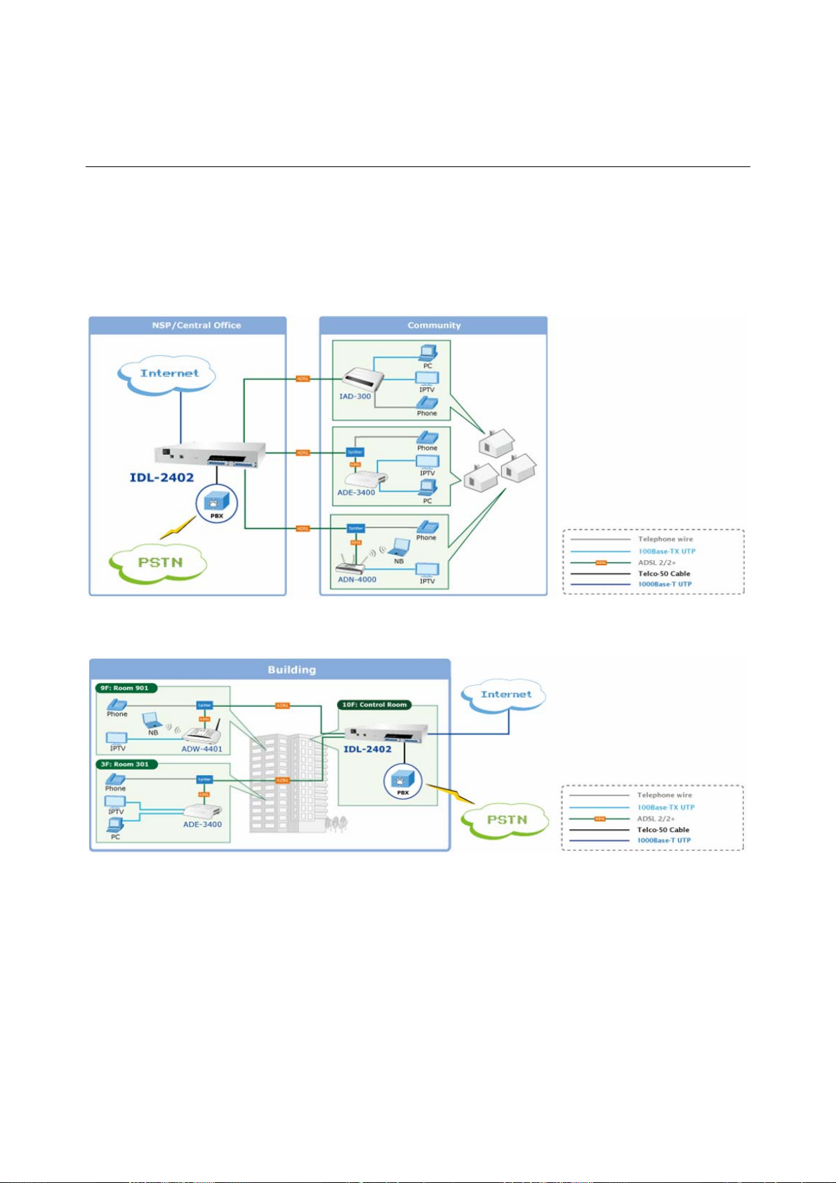
1.3 Application
The PLANET IDL-2402 offers the benefit of high performance to central office co-location
and MTU (Multi-Tenant Unit) / MDU (Multi-Dwelling Unit) markets. It provides broadband
data service over existing copper wires without affecting the conventional voice service
by 24 subscriber ports with built-in POTS splitter. A PLANET IP DSLAM is the perfect
solution for NSP a cost-effective but high-value centrally management capability.
Application 1: For Community
Application 2: For Building
- 18 -
Page 19

1.4 Outlook
1.4.1 Front Panel
The front panels of IDL-2402 are shown below.
IDL-2402
LED Definition
LED Color LED Description
SYS
ALM
DSL status
Green Normal Operation
Red Self-test fail
Green Normal Operation
Red To indicate the system alarm status
On ADSL Port is activated and linked
Green
Off ADSL Port is Disabled
Flash ADSL Port is activated but not linked
On Uplink Port connect with 100/1000Mbps Ethernet link
Orange
Uplink
Green
Off Uplink Port connect with 10Mbps Ethernet link
On Active
Off Inactive
Flash Uplink Port Transmit / receive data
Port Definition
Port Port Description
AC PWR
Uplink Port
Console Port
PHONE
LINE
AC Power cord plug-in, 100 - 240VAC is allowed.
Gigabit Ethernet port.
10/100/1000Mbps, auto-negotiaiton, auto-MDI
RS-232 port for system configuration and maintenance.
Default settings: 9600, 8, N, 1
RJ-21 connector for connecting POTS lines.
RJ-21 connector for connecting DSL lines.
- 19 -
Page 20

1.5 Technical Specifications
Product IP DSLAM
Model IDL-2402
Hardware Specification
Case
Uplink
Ports
Console
LINE
PHONE
LED Indicators
Software Specification
Standard
System
Bridge Function
VLAN Function
Multicast
1.5U high box-type with a rack-mountable enclosure
1 x RJ-45 (10/100/1000Base-T)
RS-232 Serial Port (9600, 8, N, 1)
1 x RJ-21 Connector
1 x RJ-21 Connector
1 x SYS LED
1 x ALM LED
1 x Uplink LED
24 x ADSL LEDs
Compliant with ADSL standard
− ANSI T1.413 issue 2
− G.dmt (ITU G.992.1)
− G.lite (ITU G.992.2)
− G.hs (ITU G.994.1)
Capable of ADSL2 standard
− G.dmt.bis (ITU G.992.3)
Capable of ADSL2+ standard
− G.dmt.bisplus (ITU G.992.5)
− Subscriber interface with built-in POTS splitter
− Downstream DMT data rate up to 25 Mbps
− Upstream DMT data rate up to 3 Mbps (Annex M)
− Distance up to 18 kft
− 8 PVCs per xDSL port
− DHCP forward
− DHCP relay agent
− PPPoE relay
− IPSec/L2TP/PPTP VPN pass-through function
− PPPoA to PPPoE inter-working
− Supports IPv4 packet
− Supports IEEE802.1d Ethernet bridge function between trunk Ether port
and A TM VCs
− Supports static source MAC table provisioning, automatic source MAC
learning and block duplicate ones
− Supports 4K static MAC address table
− 128 MAC address per x DSL port
− IEEE 802.1q Port-based / Protocol-based VLAN
− 512 non-stacked VLAN-ID simultaneously ranging from 1 to 4095
− VLAN stacking and VLAN cross-connect
− IP Spoofing prevention
− MAC anti-Spoofing
− Port isolation functionality
− Static VLAN group and membership provisioning
− IP multicast forwarding
- 20 -
Page 21

Function
Security
QoS
Management
− Complies with RFC2684 bridged payload encapsulation mode
− Up to 256 multicast groups and 512 copies simultaneously
− Up to 48 profile-based Multicast Access Control
− Limit maximum number of IGMP groups joined per bridge port
− IGMP snooping / proxy per IGMP v1, v2, and v3
− IGMP proxy and IGMP snooping Selection
− Supports Layer-2 frame filtering based on MAC and Ether Type
− Supports Layer-3 filtering based on IP, Protocol, and Port number
− IEEE 802.1X authentication
− Control the bandwidth occupied by broadcast, multicast, and unknown
unicast (flooding)
− Rate-limit profile binding per bridge port
− Three Color Marking (TCM) policer
− Ethernet rate limit per bridge port
− ToS (type of service) / DiffServ (differentiated services) stripping and priority
queuing
− DSCP mapping to 802.1p
− Selectable adopted priority queue mechanisms according to Strict Priority
Queue (SPQ) and Weighted Fair Queue (WFQ)
− Configurable mapping function between ATM PVC and 802.1p priority
queue
− Supports IP CoS technology
− Web based GUI management
− Local RS-232 CLI, and Ethernet SNMP / Telnet / SSH management
− Remote in-band SNMP / Telnet / SSH management
− Firmware upgradeable via FTP
SNMP v1, v2c
- 21 -
Page 22

2. Installation
The followings are instructions for setting up the IDL-2402. Refer to the illustration and
follow the simple steps below to quickly install your IP DSLAM.
2.1 Safety Instruction
The following is the safety instructions for IP DSLAM before installing.
>> The maximum operating temperature of the IP DSLAM is 65ºC. Care must be taken
to allow sufficient air circulation or space between units when the IP DSLAM is
installed inside a closed rack assembly and racks should safely support the
combined weight of all IP DSLAM.
>> The connections and equipment that supply power to the IP DSLAM should be
capable of operating safely with the maximum power requirements of the IP DSLAM.
In the event of a power overload, the supply circuits and supply wiring should not
become hazardous.
>> The AC power cord must plug into the right supply voltage. Make sure that the
supplied AC voltage is correct and stable. If the input AC voltage is over 10% lower
than the standard may cause the IP DSLAM to malfunction.
>> Generally, when installed after the final configuration, the product must comply with
the applicable safety standards and regulatory requirements of the country in which
it is installed. If necessary, consult for technical support.
>> A rare condition can create a voltage potential between the earth grounds of two or
more buildings. If products installed in separate building are interconnected, the
voltage potential can cause a hazardous condition. Consult a qualified electrical
consultant to determine whether or not this phenomenon exists and, if necessary,
implement corrective action before interconnecting the products. If the equipment is
to be used with telecommunications circuit, take the following precautions:
Never install telephone wiring during a lightning storm.
Never install telephone jacks in wet location unless the jack is specially -
designed for wet location.
Never touch un-insulated telephone wires or terminals unless the telephone line
has been disconnected at the network interface.
Caution when installing or modifying telephone lines (other than a cordless
telephone) during an electrical storm. There is a remote risk of electric shock
from lightning.
Do not use a telephone or other equipment connected to telephone lines to report
a gas leak in the vicinity of the leak.
- 22 -
Page 23

2.2 Hardware Installation
The PLANET IDL-2402 is a 1.5U high box-type IP DSLAM with rack-mountable enclosure.
It can be installed in a standard 19-inch rack by using the mounting brackets provided.
Mount the shelf on the rack using the large screws provided. The procedure to connect
and wire the system is as follows.
2.2.1 System Requirements
z Workstation with Windows NT/2000/XP
z RJ-45 cables
z RJ-11 cables
z Telco-50 cables
z RS-232 console cable
z <Optional> MDF Patch Panel (Model No.: IDL-PAN-48).
2.2.2 Installation Procedure Step 1: Ground the IP DSLAM by connecting a grounded wire (Optional).
Ground Connections
This section provides the grounding rule for the IDL-2402. All remote system sites must
be properly grounded for optimum system performance.
In Central Office:
There should be a CO GND that is adequately grounded. If the measured resistance from
the grounding screw (on the rear panel of the DSLAM, refer to below figure) to CO GND
is less than 5 Ohm, then it can be assumed that the system is well grounded. If the
measured resistance is larger than 5 Ohm, it is recommended to connect the grounding
screw to CO GND using #14 or #12 AWG wire gauge conductor.
In Remote Cabinet:
The IDL-2402 should be grounded by connecting a #14 or #12 AWG conductor between
the grounding screw (on the rear panel of the DSLAM, refer to below figure) and the earth
ground or main grounding bar. The resistance between the chassis and the grounding
bar should be less than 25 Ohm.
Rear Panel Connection
IDL-2402 grounding screw on the rear panel
- 23 -
Page 24

Step 2: Connecting the ADSL LINE and PHONE interfaces
The IDL-2402 supports 24 ports ADSL subscribers per box. There are two RJ21 50-pin
female connectors on the front panel of the system. One for ADSL line and one for POTS
interface.
To connect the subscriber lines, use cables with the RJ21 50-pin male connectors. When
installing, just plug the end of a cable with connector into the LINE and PHONE interface
female connector on the front panel. The other end of the cable is generally tied to the
MDF (Main Distribution Frame).
The pin assignment of LINE/PHONE interface is illustrated below (the numbers in the
connector figures below represent PIN numbers):
For port 1~24:
125
2650
PIN Number 1 2 3 4 5 6 7 8 ~ 18 19 20 21 22 23 24 25
Port
Number
PIN Number 26 27 28 29 30 31 32 33 ~ 43 44 45 46 47 48 49 50
Port
Number
Tip 1 Tip 2 Tip3 Tip 4 Tip 5 Tip6 Tip7 Tip8 ~ ~ Tip18Tip19Tip20Tip
Ring 1 Ring 2 Ring3 Ring 4 Ring 5 Ring6 Ring7 Ring
8
Ring18Ring19Ring20Ring
~
21
21
Tip
22
Ring
22
Tip
23
Ring
23
Tip
24
Ring
24
Note:
The MDF Patch panel is optional of standard package.
Note:
Please plug-in the RJ-21 cable with connector Tenon as below figure.
X
X
- 24 -
Page 25
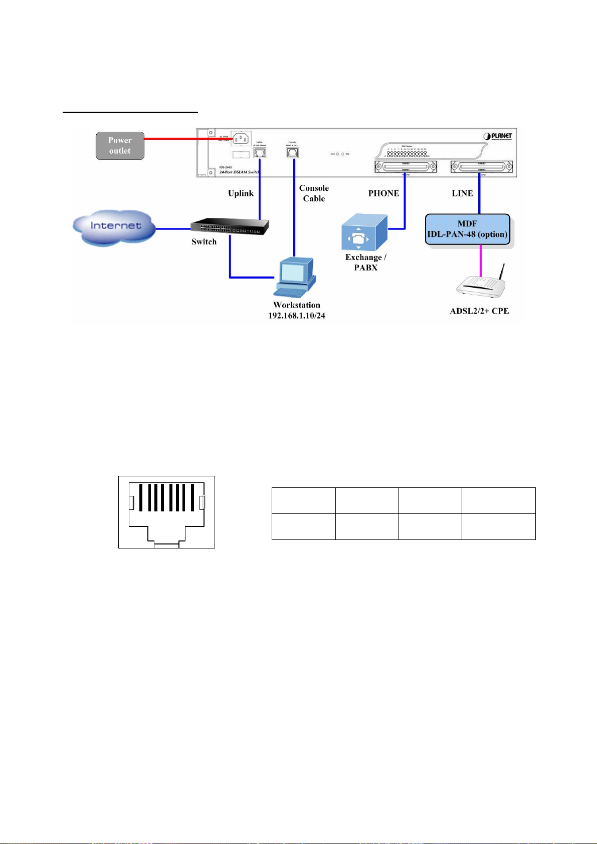
Front Panel Connection
Front panel connection of IDL-2402
UPLINK Port:
Connect to Internet by RJ-45 cable.
Console Port:
Connect to PC by RS-232 console cable in order to administer your IP DSLAM through
CLI.The Console interface on the front panel is the main control interface of the IDL-2402.
The RJ45 connector pin assignment is illustrated below:
1 2 3 4 5 6 7 8
3 4 6 Other pins
TX RX GND unused
Console Port RJ-45 pin assignment
- 25 -
Page 26
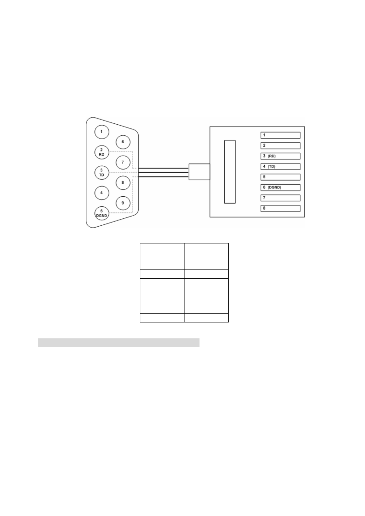
To connect the host PC to the console port, a RJ45 (male) connector-to-RS232 DB9
(female) connector cable is required. The RJ45 connector of the cable is connected to
the Console port of the DSLAM; the DB9 connector of the cable is connected to the PC
COM port. The pin assignment of the console cable is shown below:
DB-9F RJ-45M Pin
1
2
Pin 2 RD 3
Pin 3 TD 4
5
Pin 5 DGND 6
7
8
Pin Assignment of Console Cable
Step 3: Hook power cord and apply the power.
- 26 -
Page 27
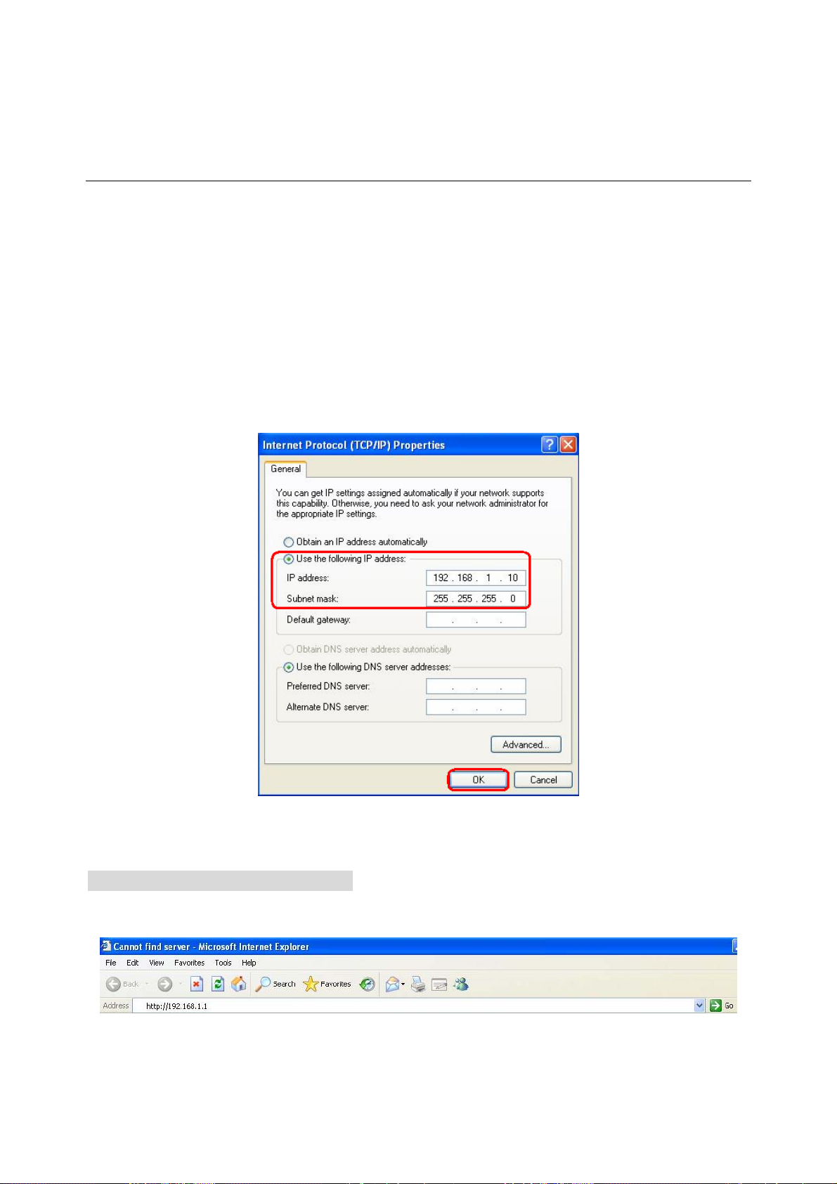
2.3 WEB Configuration
This section describes how to use Web Configuration Tool to maintain your IP DSLAM.
The IDL-2402 contains a HTTP server. You can login and configure it by using your Web
Browser.
2.3.1 System Prepartion
Before attempting to configure the IDL-2402, please ensure as below:
Set your computer’s IP with the same network mask of the router. (For example:
Router’s default IP is 192.168.1.1 / 255.255.255.0)
Then you can set computer’s IP to:
192.168.1.x / 255.255.255.0. (The range for x is from 2 to 253)
2.3.2 WEB Configuration Procedure Step 1: Using your WEB Browser
Open web browser and type http://192.168.1.1 in the browser's address box. This IP is
the default IP address of IDL-2402. Press Enter.
- 27 -
Page 28
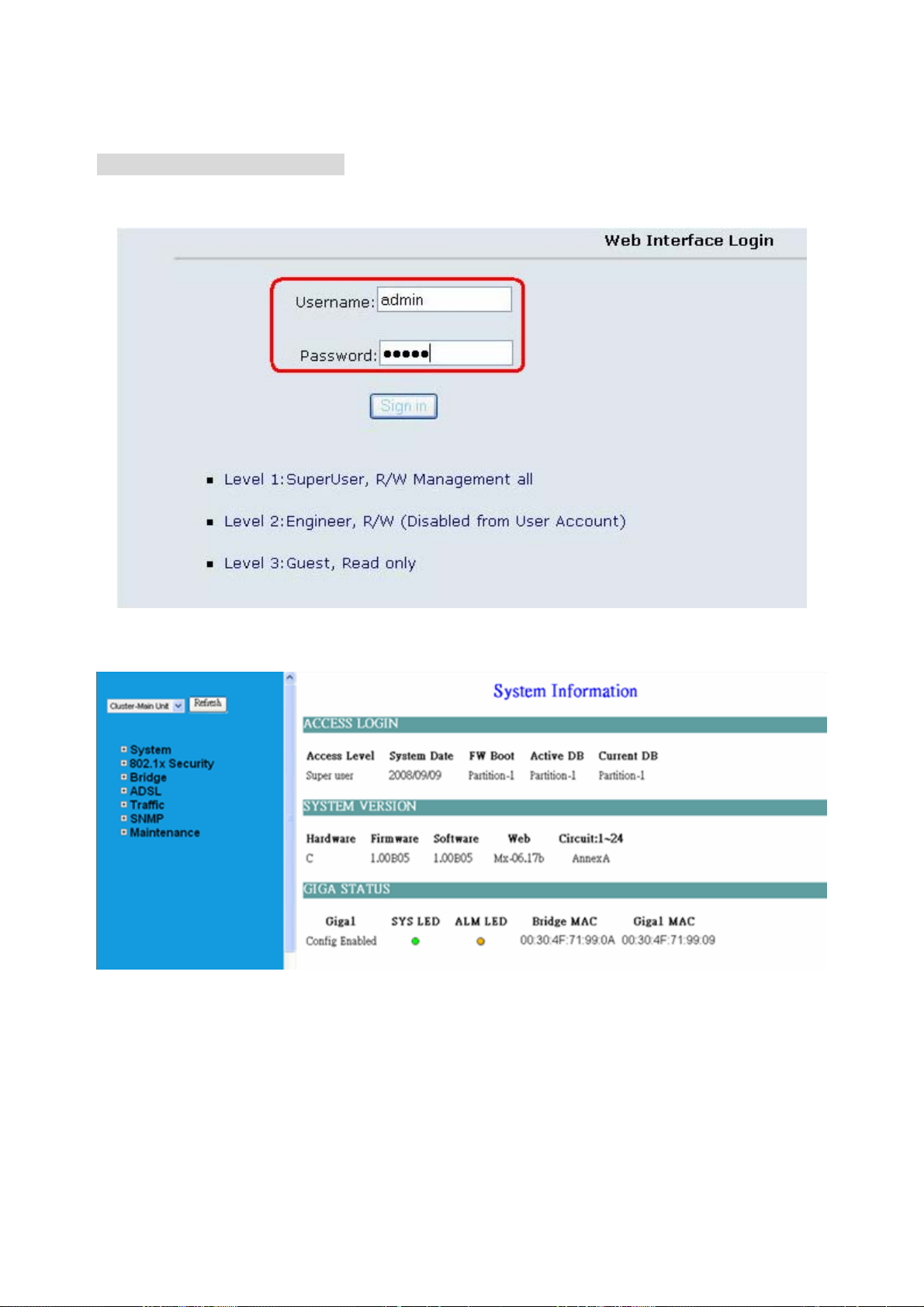
Step 2 : Login the IDL-2402
A login p age will appear. Please type your username / password and click “Sign in”. (The
default username / password is admin / admin)
After you login the IDL-2402, you will see the system information as below.
- 28 -
Page 29
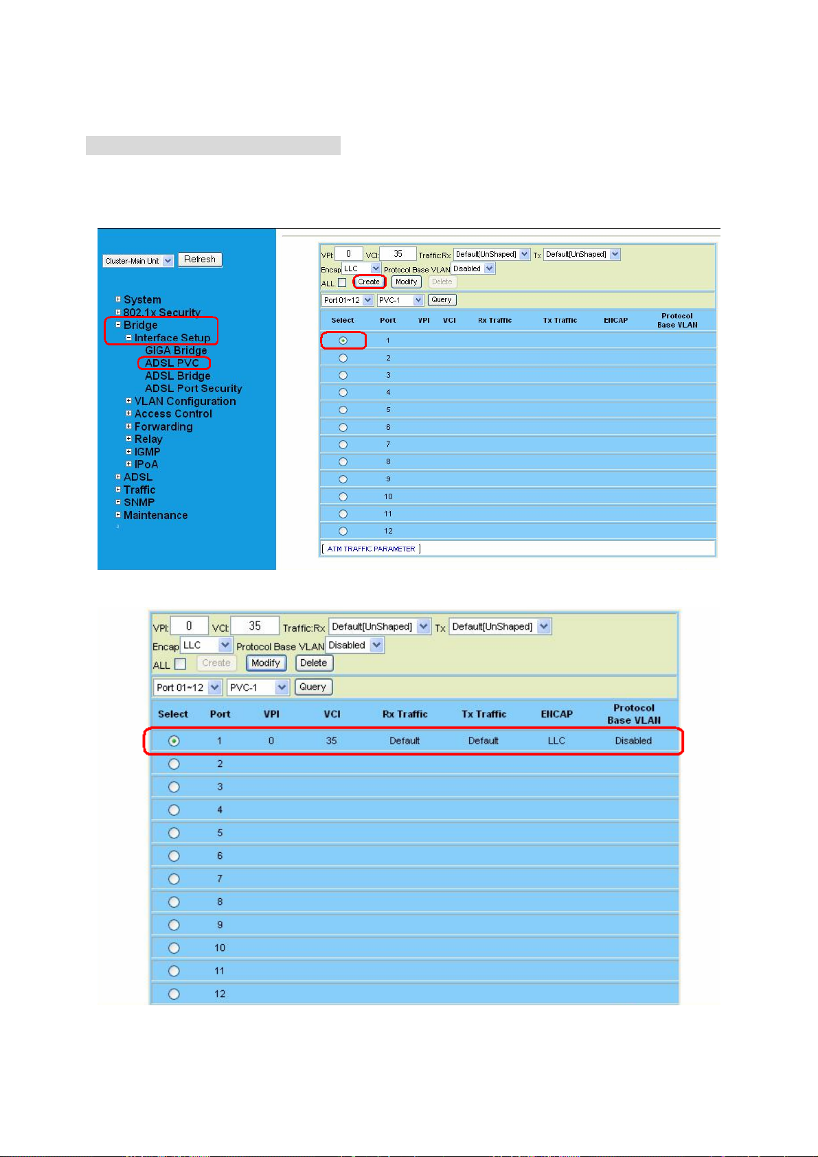
Step 3 : Configure the DSL PVC
Go to “Bridge Æ Interface Setup Æ ADSL PVC” setting screen, select the ADSL port
and click “Create” to apply the PVC settings.
For example, create PVC-1 to Port 1. The default VPI / VCI is 0 / 35.
- 29 -
Page 30
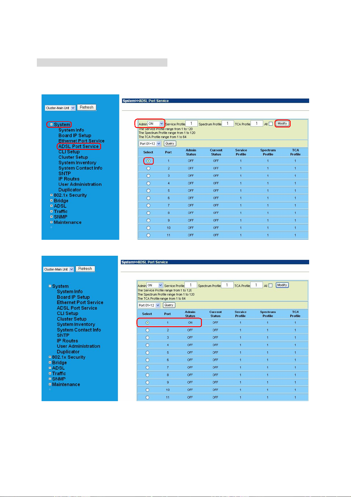
Step 4 : Enable the ADSL Port Service
Go to “System Æ ADSL Port Service” setting screen, select the ADSL port and Admin
is “ON”. Click “Modify” to make this Port is ON.
You can see the Admin status became to ON.
- 30 -
Page 31

Step 5 : Connect the ADSL2/2+ CPE to Patch Panel
Connect the ADSL2/2+ CPE to Patch Panel and configure it, the VPI / VCI value must be
the same with IDL-2402.
After finish setting, the CPE will establish the ADSL connection with IDL-2402. You can
check the connection status as below figure. The Current Status is ON.
Now the clients can access to Internet through IDL-2402.
Step 6 : Save the running configuration to Flash
Remember to save your running configuration to the flash, or the settings will be lost if
you power-off IDL-2402.
Go to “Maintenance Æ Database” setting screen, select the “(D) Save Running
Config to Flash (System Config) “. There are two partitions on flash, select your
Partition which you want to save and click “Write Running”. The configuration will save
to the Flash.
Note:
Default Partition is Partition1.
- 31 -
Page 32

2.3.3 How to backup / Restore the Configuration Configuration Import / Export
The IDL-2402 provides the configuration preservation feature that the configuration
database is stored in flash memory (two partitions available). In addition to the
configuration preservation feature, the IDL-2402 also provides the configuration
export/import feature.
DB Configuration Concept
For CLI:
Suppose that TFTP Server IP address is 172.16.100.181 and configuration file name is
‘testcfg’:
(A) Import file from TFTP Server to the Download Config and then write Download Config
to the Flash (partition 1 or partition 2).
Ex:
enable
configure
remotecfg login 172.16.100.181 get testcfg write partition <number>
- 32 -
Page 33

(B) Import file from TFTP Server to the Download Config and then load Download Config
to the Running Config.
Ex:
enable
configure
remotecfg login 172.16.100.181 get testcfg load
(C) Export: export file from Running config to the TFTP server.
Ex:
enable
configure
runningcfg login 172.16.100.181 put testcfg
(D) Save Running config to the Flash (partition 1 or partition 2).
Ex:
enable
configure
runningcfg write partition <number>
(E) Reload Flash data to the Running config
Ex:
enable
configure
runningcfg load partition <number>
(F) Set system configuration (current boot point) to factory default value
Ex:
enable
configure
restore-factory
(G) Select Configuration Flash Boot Point
Ex:
enable
configure
runningcfg active partition <number>
- 33 -
Page 34

For Web:
On the menu tree, click on Maintenance --- > Database. The Database Configuration
page is displayed. Select the database configuration action you want to perform.
(A) Import File (Write Download Config To Flash):
Type in the TFTP Server IP address and the name of the file you want to download. Then
click on Get File button.
Write downloaded Config to Flash in progress:
- 34 -
Page 35

Write to memory successfully:
Fail to Get File:
- 35 -
Page 36

(B) Import File (Load Remote Config to Running Config)
Type in the TFTP Server IP address and the name of the file you want to download. Then
click on Get File button.
Load to Running Config successfully:
Fail to Get File:
- 36 -
Page 37

(C) Export File (Put Running Config to Remote TFTP Server)
Type in the TFTP Server IP address and the name of the file you want to export. Then
click on Put File button.
TFTP put file successfully:
TFTP put file fail:
- 37 -
Page 38

(D) Save Running Config to Flash (System Config)
Click on the drop-down list and select partition, and then click on Write_Running button
to write running configuration to Flash.
Write running config to Flash successfully:
- 38 -
Page 39

(E) Reload Flash to Running Config
Click on the drop-down list and select partition, and then click on LOAD_FLASH button
to load configuration from Flash to Running Config.
Load configuration from Flash to Running Config successfully:
- 39 -
Page 40

(F) Restore Factory Default
Click on Factory_Default button to restore factory default configuration.
After loading default configuration to Flash successfully, you must click on RESTART
button to restart the system so that the configuration can take effect.
- 40 -
Page 41

(G) Flash Boot Point Configuration Select
Click on the Boot Config drop-down list and select the partition (Partition1 or Partition2)
as the boot point. Click on Apply button and then restart the system. The system will
restart and load the configuration in the partition you select into the running configuration.
- 41 -
Page 42

2.3.4 Firmware Update For CLI:
If you want to update firmware code, you must get image file from FTP Server.
Suppose that FTP Server IP address is 172.16.10.219 and the image filename is
‘vmlinux_u2402_ 1.00B05’.
Example:
1. Firmware update:
enable //go to enable mode
configure //go to configuration mode
firmware login 172.16.10.219 username share password tg123
firmware upgrade vmlinux_u2402_1.00B05
(Firmware upgrade may take a few minutes, don’t turn off or reset the system
during the process. You can get status using command ‘show firmware status’ in
Enable execution mode.)
exit //back to enable mode
show firmware status
(When status returns “Upgraded already!”, you can restart the system to run
new firmware image. Once you upgrade successfully, you can’t upgrade the
second time unless you have restarted the system.)
show firmware partition //show partition information
Current Version:1.00B05
Partition Version Date Status
------------------------------------------1 1.00B05 2007/07/05 -2 1.00B05 2007/07/10 Active
(Note: the ‘Active’ st atus of the firmware p artition information means the active
partition for next time restart, not current running partition. You can see which
partition is current running partition by referring to the Current Version. )
2. The IDL-2402 provides two firmware memory partitions. If you want to change the
firmware partition for booting, use the following commands (if you change to the
non-active partition, system will restart immediately):
enable //go to enable mode
configure //go to configuration mode
firmware partition <number> //select partition 1 or 2 for next power-on
- 42 -
Page 43

For Web:
On the menu tree, click on Maintenance --- > Firmware Update. The Firmware Update
page is displayed. Once you have entered all the necessary values, click on Firmware
Update button to start updating the firmware.
Label Description
Firmware Update
Once you have typed in the parameter values, click on this
button to start firmware update.
Remote FTP Server IP Type in the IP address of the FTP server.
Server User Name Type in the ftp user name.
Server Password Type in the ftp password.
File Name Type in the firmware filename.
Firmware Update
Status
Firmware Partition
Select
This field shows current status of firmware update process.
Select firmware memory partition (Partition 1 or 2). If you
change to the other partition (not current partition), the system
will restart immediately.
- 43 -
Page 44

This section displays the partition information including
firmware version, updating date, and status (active or
not). Note that active partition means the partition for
Partition Information
next power-up, not current partition in use. You can refer
to Current Version to know which partition is the current
partition in use. When you update the firmware, new
firmware will be written to the partition that is not
currently in use.
FTP Get in progress:
The following message is displayed during getting file from FTP server.
Firmware Write in progress:
The Flash Write process may take a few minutes; you must not turn off or reset the
system during the process.
Firmware Write successfully:
When the Flash Write process has completed successfully, the Firmware Update Status
shows “Firmware has upgraded already”. You can now restart the system.
- 44 -
Page 45

3. Software Introduction
3.1 General Overview
The software architecture of the IDL-2402 is shown in the figure below. It can be divided
into three layers: the management layer, the OAM&P layer, and the firmware layer.
Figure 3-1 Management Software Model
As in the figure, CLI shell, SNMP agent, and WEB server are in the top-most layer
(management layer) of the system software and offering OAM&P function of the DSLAM
based on the conceptual management features as follows:
Configuration Management
Performance Management
Fault Management
The IDL-2402 uses flash memory as the database (DB) to store system configuration
parameters. The firmware layer includes ADSL drivers, Memory and I/O control, etc.
- 45 -
Page 46

3.1.1 Features of Management Interface
Support CLI, SNMP (v1, v2c), and web-based GUI management interface
through in-band channels
Support up to 10 CLI sessions at the same time
The in-band management connection of the system is the highest priority of all
supported in-band traffic categories
Support Telnet interface for remote operators to login system operating console
Support up to 32 configurable SNMP trap destinations and allow the SNMP traps
to be sent to any specified SNMP aware device, for instance, Network
management center
- 46 -
Page 47

3.2 Configuration Management
The configuration management contains the following aspects:
1. System Setup, such as setup for management IP address/net mask, GBE
interface (including to enable/disable and query the administrative/operational
status of the trunk port), line port (including to enable/disable/reset ADSL port,
query the administrative/operational status of the port, and bind profiles on a per
port basis), CLI session and timeout, Cluster, SNTP, IP routes, and user
administration (including login authorization and provides three security levels).
2. Bridge Configuration (see “3.2.1 Bridge Configuration” below for more
description)
3. ADSL Configuration (see “
- 47 -
Page 48

4. 3.2.2 ADSL Configuration” below for more description)
5. ATM traffic management
6. SNMP setup
The configuration management provides detecting and reporting to the operators through
SNMP T rap for all memory updates reflecting changes in the system configuration. It also
provides logging the changes in the operational state and making this information
available (on-demand) to the operators over the operation interface.
The system contains a database (DB) to store all the provisioning data so that the
configuration can be restored in re-booting. Authorized operators can query the DB to
obtain configuration data.
3.2.1 Bridge Configuration
The bridge configuration of the IDL-2402 includes the following aspects:
Interface setup
VLAN configuration: static VLAN, protocol based VLAN, VLAN translation, and
IP/MAC anti-spoofing.
Access Control: Filtering, VLAN priority remark, rate limit, and priority queue
mapping.
Forwarding database
DSL Line Identify
IGMP configuration
IPoA configuration
- 48 -
Page 49

3.2.2 ADSL Configuration
Configuration for an ADSLx user port is provisioned by the parameter set, which is a
group of attributes that determine the user port behaviors; and we call it as a profile. The
IDL-2402 provides a profile-based provisioning per the definition of ITUT G997.1 and
RFC 2662 for ADSL line configuration data and a mechanism to associate the ADSL port
to these profiles. One or more ADSL lines may be configured to share parameters of a
single profile.
The ADSL profiles of IDL-2402 include:
Service Profile
The parameters include Rate adaptive mode selection, Min/max/planned bit rate,
Interleaving Max delay, and Minimum impulse noise protection.
Spectrum Profile
The parameters include the Power management setting, Min/max/target noise margin,
allowed ADSL modes of operation, Carrier mask, RFI band data, Maximum nominal
aggregate transmit power, Maximum PSD level, PSD shape (for ADSL2+), Power
back off initiation, and Maximum aggregate receive power.
TCA Profile
The parameters include ESs, SESs, UASs for interval and day PM, and LOS, LOF,
LOPWR, LOL, Error Frame for interval PM only.
The system provides up to 120 Service profiles and Spectrum profiles respectively,
and provides up to 16 TCA profiles. One of the profiles is a fix default that cannot be
modified; users are allowed to create, and edit the other profiles. Each profile contains
a parameter set for downstream and upstream direction respectively. Users can also
observe the actual values of these parameters through CLI, Web-GUI, or EMS.
The ADSL configuration also includes the function for user to query the line status, the
physical layer status, and the channel interface status for ATU-C and ATU-R. The status
information includes the attenuation rate, actual net data rate, the line attenuation, SNR
margin, transmission power, actual interleaving delay, channel characteristics per
subcarrier, quiet line noise PSD, …etc.
- 49 -
Page 50

3.3 Performance management
Performance management supports performance monitoring by collecting and
thresholding performance parameter counters against 15-miniute intervals for each
interface and module respectively. Users can query the data of these parameters through
CLI and Web-GUI.
Performance statistics include the following:
1. Statistics for current interval:
A real-time aspect contains the reflection of the current value situation before the
new interval. The current value includes values of current 15-min interval and
current 1-day interval.
2. Statistics history at 15-minute basis:
The system stores previous 96 statistics of PM parameters at 15-min interval for
retrieving.
3. Statistics history at 1-day basis:
The system stores previous 1 statistics of PM parameters at 1-day interval for
retrieving.
Most of the performance parameter thresholds are user-programmable. The IDL-2402
uses a threshold crossing alert (TCA) to notify the management system when one of the
counts during a measurement interval exceeds its threshold.
The TCA contains the following information:
– Specific interface involved
– Error condition identifying the measurement type
– Value of the parameter
– Occurrence date and time of the event
The performance management also provides the traffic counter including transmitted
packets, error packets and discarded packets for each interface (network and subscriber
interface) and ATM cell counter in both transmit and receive direction. Users can observe
these data through CLI and Web-GUI.
ADSL PM
The IDL-2402 provides the following ADSL PM statistics:
Item Description
ATUC_LOS Loss of signal count
ATUC_LOF Loss of frame count
ATUC_LOM Loss of margin count
ATUC_LOL Loss of link count
ATUC_ES Errored Seconds
ATUC_SES Severely Errored Seconds
ATUC_UAS Unavailable Seconds
ATUC_ReInitCounter The number of times the modem left showtime and tried to
re-initialize the line because of detection of a persistent
defect
ATUC_FailedInitCounter The number of times the modem tries to initialize the line
but fails.
- 50 -
Page 51

ATUC_CU User Total Cell Count
ATUC_CD Delineated Total Cell Count
ATUC_HEC ATM Header Error Count
ATUC_IBE Idle Cell Bit Error Count
ATUC_CVS The counter associated with the number of Coding
Violations encountered by the channel.
ATUC_FECCS The counter associated with the number of corrected
codewords encountered by the channel.
ATUR_LOS Far End Loss of signal count
ATUR_LOF Far End Loss of frame count
ATUR_LOM Far End Loss of margin count
ATUR_LPR Far End Loss of power count
ATUR_ES Far End Errored Seconds
ATUR_SES Far End Severely Errored Seconds
ATUR_UAS Far End Unavailable Seconds
ATUR_HEC Far End ATM Header Error Count
ATUR_IBE Far End Idle Cell Bit Error Count
ATUR_CVS The far end counter associated with the number of Coding
Violations encountered by the channel.
ATUR_FECCS The far end counter associated with the number of
corrected code words encountered by the channel.
The IDL-2402 provides the following ADSL PM thresholds:
NE threshold FE threshold
15min ES threshold 15min ES threshold
15min SES threshold 15min SES threshold
15min UAS threshold 15min UAS threshold
15min LOS threshold 15min LOS threshold
15min LOF threshold Not support
Not support 15min LOPWR threshold
15min LOL threshold Not support
15min ErrFrm threshold 15min ErrFrm threshold
24hour ES threshold 24hour ES threshold
24hour SES threshold 24hour SES threshold
24hour UAS threshold 24hour UAS threshold
- 51 -
Page 52

3.3.1 RMON Feature
The IDL-2402 supports performance statistics defined in RMON MIB groups 1 (Ethernet
statistics), 2 (history control), 3 (Ethernet history), 4 (alarm), 5 (event), and 6 (log) per
RFC 2819 for all network uplink 10/100/1000 ports. The supported parameters are as
follows:
Table 3-1 RMON ETH Statistics variables
Variable Description
Rx DropEvents Monitoring rx dropped packets
Rx Bytes Monitoring rx bytes packets
Rx Packet Monitoring rx packets
Rx BroadcastPkts Monitoring rx broadcast packets
Rx MulticastPkts Monitoring rx multicast packets
Rx CRC Align Errors Monitoring rx error aligment packets
Rx Undersize Pkts Monitoring rx undersize packets
Rx Oversize Pkts Monitoring rx oversize packets
Rx Fragments Monitoring rx fragments packets
Rx Jabbers Monitoring rx jabber packets
Tx Collisions Monitoring tx single collision packets
Tx/Rx Pkts 64bytes Monitoring tx/rx 64 bytes
Tx/Rx Pkts 65~127bytes Monitoring tx/rx 65 to 127 bytes
Tx/Rx Pkts 128~255bytes Monitoring tx/rx 128 to 255 bytes
Tx/Rx Pkts 256~511bytes Monitoring tx/rx 256 to 511 bytes
Tx/Rx Pkts 512~1023bytes Monitoring tx/rx 512 to 1023 bytes
Tx/Rx Pkts 1024~1518bytes Monitoring tx/rx 1024 to 1518 bytes
Tx Bytes Monitoring tx bytes packets
Tx Packet Monitoring tx packets
Tx MulticastPkts Monitoring tx multicast packets
Tx BroadcastPkts Monitoring tx broadcast packets
Table 3-2 RMON ETH History Control variables
Variable Description
HistoryDropEvents
Historybytes
Monitoring rx dropped packets
Monitoring rx bytes packets
HistoryPackets
HistoryBroadcastPkts
HistoryMulticastPkts
HistoryCRCAlignErrors
Monitoring rx packets
Monitoring rx broadcast packets
Monitoring rx multicast packets
Monitoring rx error aligment packets
- 52 -
Page 53

HistoryUndersizePkts
Monitoring rx undersize packets
HistoryOversizePkts
HistoryFragments
HistoryJabbers
HistoryCollisions
HistoryTxBytes
HistoryTxPackets
HistoryTxMulticast
HistoryTxBroadcast
HistoryUtilization
Monitoring rx oversize packets
Monitoring rx fragments packets
Monitoring rx jabber packets
Monitoring tx single collision packets
Monitoring tx bytes
Monitoring tx packets
Monitoring tx multicast
Monitoring tx broadcast
Monitoring tx Utilization
- 53 -
Page 54

3.4 Fault Management
Fault management is conceptually partitioned into two levels: the system top level, and
interface-specific level. Both levels are alarm-level configurable and can be Major and
Minor. All the alarms are mask-able.
Fault management provides the alarm output through hardware output interface (on the
system front panel) and visible indicator (LED). The alarm/status indications are
automatically generated as a result of certain events/conditions. The IDL-2402 supports
query of all current alarm status. It is also able to keep 256 records of historical alarms
and events respectively.
The IDL-2402 provides the ability to group alarms in a hierarchical alarm presentation
scheme. Alarms of the same rank can exist at the same time. A lower-ranking alarm will
be demoted if a higher-ranking alarm is raised for the same object. For example, if a
far-end LOS is raised on a circuit and then a far-end LPR is raised on the circuit, the LPR
alarm stands and the LOS closes. The alarm hierarchy used in the IDL-2402 system is
shown in the following table:
Table 3-3 IDL-2402 Alarm Hierarchy
Priority Alarm Type
Highest all activation failures (ADSL_COMMF_FE or
ADSL_NOPEER_FE)
— far-end LPR
— near-end LOS or far-end LOS
Lowest near-end LOF or far-end LOF (near-end and far-end are
independent; for example, FE-LOS does not restrain NE-LOF)
Note: 1.LOM, LCD, and NCD are not included in the alarm hierarchy; they’re treated
independently.
2.The PM counters LPR, LOS, and LOF follow the alarm hierarchy rule. When
these alarms exist at the same time, only the PM counter of a higher-ranking
alarm will count (the PM counters of other lower-ranking alarms will not).
System Alarms
The IDL-2402 provides the following System alarms:
Fan Failure Alarm
Above Temperature
Below Temperature
Self-test Fail
DSP Fail - you can see which DSP chip is fail from the user interface (Web GUI,
CLI, etc.). There is a number 1 ~ 4 in the alarm message/description
corresponding to the DSP chip 1 ~ chip 4
- 54 -
Page 55

ADSL Alarms
The IDL-2402 provides the following ADSL alarms:
LOS (Loss of Signal) -Near End/Far End
LOF (Loss of Frame) -Near End/Far End
LOM (Loss of Margin) -Near End/Far End
LCD (Loss of Cell Delineation) -Near End/Far End
NCD (No Cell Delineation) -Near End/Far End
LOPWR (Loss of Power) -Far End
COMMF: Unable to communicate with peer modem -Far End
NOPEER: No peer present – Far End
- 55 -
Page 56

3.5 Loopback Testing
The IDL-2402 supports ATM and ADSL loop diagnostics.
ATM:
The system provides F5 end-to-end or segment loopback.
ADSL:
The system provides Dual Ended Loop Testing (DELT) for each ADSL line on a per port
basis, according to the definition per section 8.12.3 of ITUT G992.3.
The following test parameters are supported:
- Channel Characteristics Function H(f) per subcarrier (CCF-ps),
- Quiet Line Noise PSD QLN(f) per subcarrier (QLN-ps),
- Signal-to-Noise Ratio SNR(f) per subcarrier (SNR-ps),
- Line Attenuation (LATN),
- Signal Attenuation (SATN),
- Signal-to-Noise Ratio Margin (SNRM),
- Attainable Net Data Rate (ATTNDR),
- Far-end Actual Aggregate Transmit Power (ACTATP),
- Near-End Actual Aggregate Transmit Power (ACTATP).
- 56 -
Page 57

3.6 Cluster Feature
The IDL-2402 supports Cluster feature that can make a group of NEs (network elements)
work together as a single NE from the management point of view. Operators can manage
the NEs in a cluster, called cluster nodes, via the same single IP address in terms of CLI,
Web-based GUI or SNMP based management interfaces. The IDL-2402 currently
provides cluster feature that a cluster can include up to four cluster members (NEs).
There are one Master and the other members are all Slaves in a cluster. The Master
works as a gateway of the Slaves, and it also can forward CLI/Web/SNMP commands to
the destination Slave. The Slaves can execute the commands and respond to the Master.
It uses star topology for conducting a Clustering Management group.
Figure 3-2 Cluster network topology – Star
Before you group a Master and a Slave IPDSLAM, some parameters need to be well
configured:
1. Cluster domain name: The group name for a cluster must be the same on
Master and Slave.
2. Cluster IP address: IP address to be used for remote management when Master
and Slave are grouped together.
3. NE cluster name: A name to identify Master or Slave.
4. Set private IP address on in-band port for both Master and Slave IPDSLAM. The
private IP is used for communication between Master and Slave. The
management center actually uses Cluster IP address for remote management.
5. Master and Slave need to be configured with same management VLAN.
6. The default gateway should be configured to the router that is aware how to route
management traffic to Management Center of the management network. The
setting of Cluster default gateway should be the same between Master and
Slave.
- 57 -
Page 58

4. WEB Management
Web Configuration Tool Overview
To access Web Configuration Tool on an IDL-2402:
1. Connect a PC to the console port of the DSLAM. At the console, type the following
CLI command:
WDS:>enable /*enter the enable command mode from initial mode*/
WDS:%show management all /*display all in-band management IP setting*/
The default LAN IP address is got via DHCP.
2. At your web browser, enter the URL you retrieve by using the above command. If
you need to change the accessing port number (default is 80) of the Web
Configuration Tool, use the following CLI command (with the correct values added):
WDS:%configure /*enter the configuration command mode from enable
mode*/
WDS:(conf)#http port <number> /*set http port number*/
3. Logging in to Web Configuration Tool:
Once you connect to the DSLAM, a login page is displayed. You must enter your
username and password to access the pages. The default login username and password
are as follows:
User Name: admin
Password: admin
Click on the Sign in button.
You are now ready to configure your DSLAM using the Web Configuration Tool.
Figure 4-1 Web Configuration Tool login page
- 58 -
Page 59

4. The following page is displayed. This is the homepage of the Web Configuration
Tool.
Figure 4-2 Web Configuration Tool homepage
- 59 -
Page 60

About Web Configuration Tool Pages
The Web Configuration Tool provides a series of web pages for users to setup and
configure the IDL-2402 System. These pages are organized into six main topics including
System, Bridge, ADSL, Traffic, SNMP, and Maintenance. You can select each topic
from the menu on the left-hand side of the main window. Table 4-1 lists the various pages
of the web configuration tool.
The exact information displayed on each web page depends on the specific configuration
that an operator is using. The following chapters provide a general description of the
setup and configuration details.
Table 4-1 Pages of the Web Configuration Tool
System
Bridge
System Information
Board IP Setup
Ethernet Port Service
ADSL Port Service
CLI Setup
Cluster Setup
System Inventory
SNTP
IP Routes
User Administration
Duplicator
System Protocol 802.1x Security
RADIUS & Local Profile
GIGA Bridge
ADSL PVC
Interface Setup
ADSL Bridge
ADSL Port Security
Static VLAN
VLAN Configuration
Access Control
Forwarding
- 60 -
Protocol Based VLAN
Translation VLAN
Static Allowed IP
MAC Spoofing
Filtering
VLAN Priority Remark
Rate Limit
Priority Queue Mapping
TP Forwarding DB
Forwarding Static
Page 61

Relay
IGMP
IPOA
ADSL
Profile
Data & Inventory
Line Config & Info
Traffic ATM Traffic Descriptor
SNMP
SNMP Community
SNMP Target
DSL Line Identify
Protocol & Route Port
IGMP Profile
IGMP Multicast
BRAS MAC
Interface Setup
Service Profile (main)
Service Profile (Channel)
Spectrum Profile (main)
Spectrum Profile (ADSLx)
TCA Profile
Inventory
Loop Test
Carrier Data
OP Data
Line Configuration
Line Information
Maintenance
SNMP Notify
SYS Log Server
Database
Firmware Update
ATM Loopbacks
Fault Management
Performance Monitoring
Alarm/Event
Alarm Profile
Hardware Temp.
System Utilization
Ethernet Statistics
ATM Statistics
RMON
ADSL Day/Interval
- 61 -
Page 62

4.1 System
4.1.1 System Information
The System Information page (the default page you’ll see after you login the web
configuration tool) contains information about the user access level, current system date
and time, current boot configuration partition, system MAC address, system HW/SW/FW
version, web configuration software version, supported subscriber line type (AnnexA or
AnnexB), GBE interface status, and LED status (SYS and ALM).
From the System menu, click on System Info. The following page is displayed:
System Information Page
- 62 -
Page 63

4.1.2 Board IP Setup
This option allows you to configure the in band IP address setting, VID management
setting, HTTP port setting, etc. From the System menu, click on Board IP Setup. The
following page is displayed:
Board IP Setup Table
Label Description
In Band
Address
Inband VID
Management
HTTP Port
Remote IP
System Name You can modify the name of the system here.
Modify Click on this button to submit the modification.
RESTART Click on this button to restart the system.
IP Address Type in the IP address of the DSLAM for in-band management.
Subnet Mask Type in the in-band su bnet mask of the DSLAM.
No Limit VID
Limit VID The VLAN ID for individual in-band management VLAN.
Priority
Select this checkbox if no specific in-band management VLAN is
required, and the setting in "Limit VID" parameter will be ignored.
Select the VLAN priority level (0~7) of the in-band management traffic
sent out from GBE port.
Shows current HTTP port setting for Web access. You can modify http
port setting in this field.
Shows the IP address of the management PC currently connected to
this DLSAM.
- 63 -
Page 64

4.1.3 Ethernet Port Service
This option allows you to set the administration state and select the speed mode for the
Gigabit Ethernet ports. From the System menu, click on Ethernet Port Service. The
following page is displayed:
Ethernet Port Service Setup
Label
Port This field shows port number of the Gigabit Ethernet interface.
Admin Status
Selected Speed
Link Status Show operational status of the trunk ports (ON/OFF).
Current Speed Show current speed mode of the trunk ports.
Current Media
Modify Click on this button to submit the modification.
Click on the drop-down list and select the administrative state
(ON/OFF) to enable/disable the GBE port.
Click on the drop-down list and select the speed mode for trunk
GBE port. Supported options are: AutoNegotiate, 100Mbps Half
(duplex), 100Mbps Full (duplex).
Show current uplink transmission medium (via copper or SFP). This
field will show N/A when O per Status is OFF.
Description
- 64 -
Page 65

4.1.4 ADSL Port Service
This option allows you to setup the service status of the line ports and to bind the
selected service profiles and spectrum profiles. Also, you can query current setting and
the operational status of the line ports. From the System menu, click on ADSL Port
Service. The following page is displayed:
First click on the drop-down list to select the port range to be displayed. Remember to
click on the radio button to select a port to be modified (or select the All checkbox to
modify all ports of the page at a time).
Table 0-1 ADSL Circuit Setup
Label Description
Admin
Service Profile Type in the index of the Service Profile (1~120).
Spectrum Profile Type in the index of the Spectrum Profile (1~120).
Click on the drop-down list and select the Administ rati ve status: ON, OFF, or
RESET.
- 65 -
Page 66

TCA Profile Type in the index of the TCA Profile (1~64).
All Select the check box to select all circuits of current page.
Modify Click on this button to submit the modification.
Query Click on this button to get most recent status of the circuits.
Select Click on the radio button to select the po rt to be modified.
Current Status
This field shows the operational status of the line ports. Possible values are
ON (enabled), OFF (disabled), and Testing (in loop testing now).
- 66 -
Page 67

4.1.5 CLI Setup
This option allows you to modify the timeout setting for a CLI session and the allowable number of
CLI sessions. From the System menu, click on CLI Setup.
CLI Setup
Label Description
CLI Session Allowable number of CLI sessions at the same time. Valid value: 1~10.
CLI Timeout
Default
Modify Click on this button to submit the modification.
CLI session will be closed once the idle time exceeds this timeout value.
Valid value: 180~3600 (sec).
Click on this button to set default values (CLI session: 5, CLI timeout: 300
sec).
- 67 -
Page 68

4.1.6 Cluster Setup
This option allows you to setup Cluster function, which can make a group of NEs (network
elements) work together as a single NE from the management point of view. Before you group a
Master and a Slave IPDSLAM, some parameters need to be well configured:
1. Cluster domain name: The group name for a cluster must be the same on Master and Slave.
2. Cluster IP address: IP address to be used for remote management when Master and Slave
are grouped together.
3. NE cluster name: A name to identify Master or Slave.
4. Set private IP address on in-band port for both Master and Slave IPDSLAM. The private IP is
used for communication between Master and Slave. The management center actually uses
Cluster IP address for remote management.
5. Master and Slave need to be configured with same management VLAN.
6. The default gateway should be configured to the router that is aware how to route
management traffic to Management Center of the management network. The setting of
Cluster default gateway should be the same between Master and Slave.
Currently a IDL-2402 cluster can support up to four cluster members (NEs). The IPDSLAMs in a
cluster must all be in-band connected through the GBE port. It uses star t opology for conducting a
Clustering Management group.
Cluster network topology – Star
From the System menu, click on Cluster Setup. The following page is displayed:
By default, the DSLAM is not in a cluster. The st ate of the Cluster Configuration shows “IDLE” and
the Role shows “Individual”.
- 68 -
Page 69

To make the DSLAM join a cluster, select the Role as “Cluster” or “Slave only” according to your
plan and then click on Modify. The state of the Cluster Configuration will show from
DISCOVERING to VOTING to MASTER or SLAVE at last.
The following figure shows the Cluster Setup page of a cluster containing two cluster members.
You will see the following page if you’re connecting directly to the Master via its in-band IP
address or connecting to the Cluster IP “172.16.77.88”. You can control all the IP DSLAMs in a
cluster by connecting to the Cluster IP address, or by directly connecting to the Master IPDSLAM
via its in-band IP address that is configured in the Board IP Setup page (refer to section 4.1.2).
Cluster Setup
Label Description
Name Type in the NE name in the cluster.
Domain Type in the name of the cl uster domain.
Role
Voting Key
Valid options are: Cluster (Master or Slave is decided by the system), Slave only (role of the
DLSAM is always Slave), and Individual (not in a cluster).
Type in 0 or a positive integ er as th e priority to be Master. 0 means to let system decides
Master and Slaves. If positive integer is typed in, the smaller the number is, the higher priority
- 69 -
Page 70

for the DSLAM to be a master in a cluster. But if there’s already a Master in a cluster, a new
added DSLAM cannot try to be the Master by entering a smaller voting key number; the
Master cannot be changed in this way.
IP
Netmask Type in the cluster’s subnet mask.
Gateway Type in the cluster’s gateway IP address.
ID This field shows Cluster ID, which indicates cluster ordering.
Modify Click on this button to submit the modification.
Query Click on this button to query current status.
Type in the cluster IP address. Users can connect to and manage the cluster via the cluster
IP address through in-band connection.
To control a member in the cluster:
Select a Cluster member from the drop down list above the menu tree. Then you are controlling
that NE now.
Every time you modify the setting (for example, changing the Role) of any cluster member, the
cluster will be reconstructed (cluster state Discovering Æ Voting Æ Master or Slave).
If you modify the Role to “Individual”, Cluster State will show ‘IDLE’. The DSLAM is not in a cluster
now.
If you are directly connecting to a Slave in the cluster (connecting via its in-band IP address) you
cannot switch to any other member in the cluster.
- 70 -
Page 71

4.1.7 System Inventory
This option allows you to retrieve the system inventory including Description of the
System, HW/FW/SW Version, Model Information, Part Number, Hardware Revision, and
Serial Number. From the System menu, click on System Inventory. Click on the Query
button. The following page is displayed:
- 71 -
Page 72

4.1.8 System Contact Info
This option allows you to specify the system name, system contact, and system location.
From the System menu, click on System Contact Info. The following page is displayed:
Type in the value you desire, and then click on Modify to apply the setting. Click on
Query to verify if the value is changed.
- 72 -
Page 73

4.1.9 SNTP
This option allows you to setup the Simple Network Time Protocol (SNTP). From the
System menu, click on SNTP. The following page is displayed.
SNTP Setup
Label Description
Sets the local time zone by selecting in the Time Zone drop-down list.
Time Zone
System Date Sets system date (yyyy/mm/dd).
System Time Sets system time (hh:mm:ss).
Polling Interval
SNTP Server address
Modify Click on this button to submit the modification.
Sixty-five of the world’s time zones are presented (including those using
standard time and summer/daylight savings time).
Sets the polling interval (in seconds) that SNTP client will sync with a
designated SNTP server.
Sets the dedicated unicast server IP address for which the SNTP client can
synchronize its time.
- 73 -
Page 74

4.1.10 IP Routes
This option allows you to configure the IP route table for the in-band management traffic.
From the System menu, click on IP Routes. The following page is displayed:
Click on the drop-down list to select the page to be displayed first.
IP Route Setup
Label Description
This field shows current system default gateway. You can modify the
gateway address by typing in new value and then click on Set.
System Gateway
ADD Next Click on this button to add a new IP route.
Destination Type in the destination IP address for the new IP route.
Net Mask Type in the subnet mask for the new IP route.
Gateway Type in the IP address of the gateway for the new IP route.
Delete Select
If the DSLAM is a Slave in a cluster, this field shows the in-band IP address
of the Master; if the DSLAM is a Master in a cluster, this field shows the IP
address of the Cluster gateway.
Click on the radio button to select a route and then click on Delete to remove
this route from the table.
- 74 -
Page 75

4.1.11 User Administration
This option allows you to administer accounts for users who access the DSLAM. From
the System menu, click on User Administration. Click on Select: drop-down list and select
a page to display. The following page is displayed:
User Administration
Label Description
Page Click on the drop-down list and select the page to be displayed.
Click on this button to create a new user. You will enter the following page:
New
Once you have typed in all the information for the new user, click on the
Create button.
Delete / Modify
Click on the radio button on the leftmost column of the user table to select
the user you want to delete / modify. Then click on Delete / Modify button.
Note that the default admin user cannot be deleted.
- 75 -
Page 76

User Name Shows the name of the user (up to 32 characters).
The available access levels include:
Level
SUPERUSER, ENGINEER, and GUEST.
Aging day Set password expiration days (0 for no expiration days)
Start Date Shows the day when the account was first created.
Last Login Shows the day when a user last login.
Comment Description about the user account (up to 31 characters).
When a new account is added: (for example, Test1 is added)
When user Test1 intends to login for the first time, he will be asked to change his
password and then login with the new password.
- 76 -
Page 77

4.1.12 Duplicator
This option allows you to duplicate all/partial the configurations of one selected line port
(as a template) to other ports (as many as you want). From the System menu, click on
Duplicator. The following page is displayed. Select the content of configurations (ADSL
line configuration, ADSL profiles, or…) you want to duplicate first. Then specify the port
number as the template (the source port to be copied), and select the target ports to
which the template is going to be copied. At last click on Paste to apply.
- 77 -
Page 78

4.2 802.1x Security
4.2.1 System Protocol
This option allows you to enable/disable 802.1x authentication function of the system,
and setup the 802.1x authentication mechanism for each line bridge port. Before you
setup 802.1x for a line bridge port, you must create the ADSL PVC (bridge port) first.
Authentication
Authenticator
Supplicant
(line user)
(Our system)
From the 802.1x Security menu, click on System Protocol. The following page is
displayed:
Main Setting
Server
(RADIUS)
- 78 -
Page 79

System Protocol Setup - Main Setting
Label Description
System Authentication section
Click on the drop-down list to enable or disable the 802.1x authentication function of the system. If you
select “Disabled”, any setting in the Port Authentication section will not take effect.
Port Authentication section – Main Setting
Select Port
Enable
Accounting Control
Accounting Interval
Port Control
Select the line bridge port range to be listed.
Remember to select the checkbox when you want to modify/delete the
setting of a bridge port or set a bridge port to its default value.
OFF/ON: disable/enable 802.1x authentication function for the bridge
port. When 802.1x is disabled, the system allows bidirectional normal
traffic in this port in spite of its authentication state. Default is OFF.
OFF: notify RADIUS server to stop accounting for this port.
ON: notify RADIUS server to start accounting for this port.
Default is OFF.
Type in the interval (300 ~ 600 sec) between accounting information
updates. Default is 300 sec.
Force-unAuth: cause the port to stay in the unauthorized state, ignoring
all attempts by the client to authenticate.
Force-Auth: disable 802.1X authentication and cause the port to
transition to the authorized state without any authentication exchange
required.
Auto: enable 802.1x authentication and cause the port to begin the
authentication process from unauthorized state.
Max Request
Authenication
ReAuthentication Control
Max Request Type in the number of times our system will send authentication
ReAuthentication
Type in the number of times our system will send authentication requests
to Supplicant if no response from the Supplicant is received. Default value
is 2.
OFF: disable re-authentication after a period of time
ON: enable re-authentication after a period of time
Default is OFF.
requests to the authentication server (RADIUS) if no response from the
server is received. Default value is 2.
- 79 -
Page 80

Timer Setting
- 80 -
Page 81

System Protocol Setup – Timer setting
Label Description
Port Authentication section – Timer Setting
Select the line bridge port range to be listed.
Select Port
Supplicant Timeout
Server Timeout
Tx Period
ReAuthentication Period
Quiet Period
Remember to select the checkbox when you want to modify/delete the
setting of a bridge port or set a bridge port to its default value.
Type in the number of seconds our system will wait for a response before
resending the request to the supplicant. Default is 60 (sec).
Type in the number of seconds our system will wait for a reply before
resending the response to the authentication server. Default is 60 (sec).
Type in the number of seconds our system will wait for a response to an
EAP-request/identity frame from the supplicant before resending the
request. Default is 30 (sec).
Type in the number of seconds between re-authentication requests. Default
is 3600 (sec).
Type in the number of seconds that our system remains in the quiet state
following a failed authentication exchange with the supplicant. Default is 60
(sec).
- 81 -
Page 82

4.2.2 RADIUS &Local Profile
The IDL-2402 system supports RADIUS client function for authenticating line ports with local
authentication database or remote RADIUS server. From the 802.1x Security menu, click on
RADIUS & Local Profile. The following page is displayed:
RADIUS & Local Profile Setup
Label Description
Authentication Method section
In this section, operators setup four AAA methods for the system to use, and the priority order is Method1 >
Method2 > Method3 > Method4. If a user cannot be authenticated when the system uses Method1, the
system will then try to use Method2, and so on. Click on the AAA method drop-down list and select a
RADIUS server index or the local profile, which has been already configured in the RADIUS Server section
or Local Profile section. At last click on Modify button.
RADIUS Server section
Select (Index#n)
RADIUS Server IP Type in the IP address of the remote RADIUS server.
Authentication Port
Accounting Port
Remember to select the checkbox when you want to modify or delete a
RADIUS server entry.
Type in the port number for RADIUS Authentication in the Layer-4
header. Default is 1812.
Type in the port number for RADIUS Accounting in the Layer-4 header.
Default is 1813.
- 82 -
Page 83

Max Fail
Type in the maximum allowable times of continuously failed
authentication attempts.
VLAN ID Type in the VID of the VLAN which the RADIUS server belongs to.
Secret ID Type in the authentication key in text format.
Local Profile section
Click on the drop-down list and select the profile range to be listed.
There are total 8 pages and 8 profiles per page (up to 64 local profiles
can be set in our system).
Username Type in the username for authentication.
Password Type in the password for authentication.
- 83 -
Page 84

4.3 Bridge
4.3.1 Interface Setup
4.3.1.1 GIGA Bridge
This option allows you to setup the GBE (trunk) bridge interface. From the Bridge menu,
click on Interface Setup and then GIGA Bridge. The following page is displayed:
GIGA (Trunk) Bridge Setup
Label Description
Mode
Click on the drop-down list and specify the trunk port to be an Uplink or User
(especially for system stacking ).
VID Type in the default port VLAN ID. Valid value is 1 ~ 4094.
Max MAC
VLAN
Ingress
Type in the maximum number of MAC addresses that can be learned by the giga
bridge port (1 ~ 4096).
VLAN setting for the traffic. Includes three drop-down lists:
Pri-0 ~ 7: Set the default VLAN priority level.
UnTagged/Tagged: Select to untag / tag the outgoing (upstream direction for
trunk bridge ports) packet s. If UnTagged is selected, a double-tagged packet will
leave single-tagged (the outer most VLAN tag is removed) and a single-tagged
packet will leave untagged.
no Stack/Stack: Disable/Enable N:1 VLAN stacking (our system adds the
default VLAN tag to all the incoming frames through this port).
Note: When an untagged frame enters the IDL-2402, it is assigned the default
PVID of the ingress (incoming) bridge port and become a single-tagged frame
no matter VLAN stacking is enabled or not.
Set Ingress ON: check if the VID of the incoming frame is in the member set. If
not in the member set, block the frame.
Set Ingress OFF: Ingress filter disabled.
Acc.Frm
Click on the drop-down list and select to accept ALL Frame, only VLAN tagged
frame, or only Untagged frame.
- 84 -
Page 85

ON/OFF: to enable/disable isolation. When port isolation is enabled, packets
Isol
received from a trunk port (when both the trunk interfaces are configured as
up-link) cannot be forwarded to the other trunk port even for broadcasting.
To modify the configuration of a giga port:
1. Click on the radio button to select trunk port 1
Modify
2. Change the parameter values
3. Click on Modify button to apply new values
Query Click on this button to query current status.
- 85 -
Page 86

4.3.1.2 ADSL PVC
This option allows you to setup the ADSL PVC. From the Bridge menu, click on Interface
Setup and then ADSL PVC. The following page is displayed:
You shall click on the drop-down lists to select port range and PVC first. Then the data of
these PVCs (bridge ports) you selected will be displayed. Click on the radio button to
select the PVC you want to create, modify, or delete.
ADSL PVC Setup
Label Description
VPI Type in the VPI value: 0 ~ 255. Default value is 0.
VCI Type in the VCI value: 21, 32 ~ 65535. Default value is 35.
Click on the drop-down list and select a traffic type for transmit and receive
Traffic
direction respectively. Available options are created in the ATM Traffic
Descriptor page. See section 4.5.1
- 86 -
Page 87

Encap
Protocol Based VLAN
Select AAL5 Encapsulation Type: VCMUX, LLC, or AUTO (for PVC#1 ~
PVC#4 only)*.
Select in the drop-down list to enable or disable protocol based VLAN
function. When protocol based VLAN is enabled, the bridge port will work
according to the protocol based VLAN table (refer to section 4.3.2).
All
Create
Modify
Delete
Query Click on this button to get the most recent data.
Select the check box to copy specified circuit to all remainder circuits in
current page.
Click on the radio button to select a PVC (bridge port) that has not been
created. Set the parameter values and then click on Create to create a PVC.
Click on the radio button to select the PVC (bridge port) you want to modify.
Change the parameter values and then click on Modify.
Click on the radio button to select the PVC (bridge port) you want to delete.
Then click on Delete to remove the PVC.
*The IDL-2402 supports auto-detection of the ATM AAL5 encapsulation method, LLC or
VC-Mux. Meanwhile, the IDL-2402 is also able to automatically sense the following
protocol encapsulations: PPPoE over ATM (per RFC 2684), IPoE over ATM bridge mode,
and PPP over ATM. IPoA works on individual PVC.
However, there are limitations on auto-detection of encapsulations:
1. LLC/VC-Mux automatically detection is only applicable to PVC#1 ~ PVC#4 of each
ADSL port. PVC#5 ~ PVC#8 must be assigned the ATM AAL5 encapsulation method
manually.
2. PPPoA works only for PVC#1 ~ PVC#4 and the LLC/VC-Mux automatically detection
must be enabled.
Refer to section 4.3.7 for IPoA configuration.
- 87 -
Page 88

4.3.1.3 ADSL Bridge
This option allows you to setup the ADSL bridge interface. From the Bridge menu, click
on Interface Setup and then ADSL Bridge. The following page is displayed:
You shall click on the drop-down lists to select port range and PVC first. Then the data of
these PVCs (bridge ports) you selected will be displayed. Click on the radio button to
select the bridge port you want to modify.
ADSL Bridge Setup
Label Description
VID Type in the default port VLAN ID. Valid value is 1 ~ 4094.
VLAN setting for the egress traffic. Includes three drop-down lists:
VLAN
UnTagged/Tagged: select untagging/tagging the outgoing frames
(downstream direction for line bridge port). If UnTagged is selected, a
double-tagged packet will leave single-tagged (the outer most VLAN tag is
- 88 -
Page 89

Ingress
removed) and a single-tagged packet will leave untagged.
Pri-0 ~ 7: set the default VLAN priority level.
no Stack/Stack/TLS: disable N:1 VLAN stacking / enable N:1 VLAN
stacking (our system adds the default VLAN tag to all the incoming frames
through this port) / enable TLS (transpar ent LAN service) so that this bridge
port becomes VLAN transparent (refer to DSL Forum, TR-101). A
pre-configured S-Tag is used to encapsulate TLS traffic going through this
port. That is, an S-Tag (PVID here) will be added to all the upstream frames
received on this port, and the C-Tags will be the original tags of these
frames (no C-Tag for untagged incoming frames). On the other hand, the
S-tag will be removed from all the downstream (outgoing) frames.
Note: When an untagged frame enters the IDL-2402, it is assigned the
default PVID of the ingress (incoming) bridge port and become a
single-tagged frame no matter VLAN sta cking is enabled or not.
Set Ingress ON: check if the VID of the incoming frame is in the member set. If
not in the member set, block the frame.
Set Ingress OFF: Ingress filter disabled.
AccFrm
Isolation
Priority Force
All
Modify
Click on the drop-down list and select to accept ALL Frame, only VLAN tagged
frame, or only Untagged frame.
ON/OFF: to enable/disable isolation. When port isolation is enabled, packets
received from a line bridge port (including trunk interface configured as
user-link) cannot be forwarded to any other line bridge port even for
broadcasting.
Click on the drop-down list and select the priority-forcing mode. Options are:
Disabled: Reserve the original priority of all packets.
Ingress: Force applying the default VLAN priority value to all the packets
received on this bridge port (so this rule will work on all the
member-set of this bridge port).
Egress: Force the priority value of all packets sent out from this bridge port’s
default VLAN to be the default VLAN priority (so this rule only works
on default VLAN of this bridge port).
Both: Combine the rules of Ingress and Egress.
Select the check box to copy specified circuit to all remainder circuit s in current
page.
Click on the radio button to select the bridge port you want to modify. Change
the parameter values and then click on Modify.
Query Click on this button to get the most recent data.
- 89 -
Page 90

4.3.1.4 ADSL Port Security
This option allows you to setup the ADSL port security. From the Bridge menu, click on
Interface Setup and then ADSL Port Security. The following page is displayed:
You shall click on the drop-down lists to select port range and PVC first. Then the data of
these PVCs (bridge ports) you selected will be displayed. Click on the radio button to
select the bridge port you want to modify.
ADSL Port Security Setup
Label Description
Max MAC
MAC Learning
IP Allowed
Type in the maximum number of MAC addresses that can be learned by the
ADSL bridge port (1 ~ 128).
Select to enable/disable MAC learning ability. Sometimes you can disable
MAC learning on specified bridge port. This function is for 1:1 VLAN
translation scenario.
Select to enable/disable IP Allowed function. When you enable IP Allowed
function on a bridge port, this bridge port will work according to the Static
Allowed IP table (refer to section 4.3.2).
- 90 -
Page 91

So you need to define the source IP addresses that bind to this bridge port.
Then the IP packets that contain these source IP addresses can pass
through this bridge port; otherwise the packets will be blocked.
All
Modify
Select the check box to copy specified circuit to all remainder circuits in
current page.
Click on the radio button to select the bridge port you want to modify.
Change the parameter values and then click on Modify.
Query Click on this button to get the most recent data.
- 91 -
Page 92

4.3.2 VLAN Configuration
4.3.2.1 Static VLAN
This option allows you to configure the static VLAN table. From the Bridge menu, click on
VLAN Configuration and then Static VLAN. The following page is displayed. Click on the
radio button to select CONFIG VLAN to configure static VLAN for the bridge ports or
SHOW VLAN to display the VLAN table.
CONFIG VLAN
Click on the drop-down list to select ADSL or GIGA port, and then select a port and PVC if
ADSL is selected. Once you have selected the bridge interface, its current static VLAN
setting is displayed. To add a new VLAN member, type in VID for the New VID field and
then select Tagged/UnTagged for VLAN Tag, ON/OFF for Isolation, and VLAN priority
level (specify a number or reserve the original value) for Priority. At last click on
Create==> button. To modify or delete a VLAN, select the checkboxes of the entries you
want to modify or delete and then click on Modify or Delete button.
- 92 -
Page 93

SHOW VLAN
In the following page, type in the VID and then click on Query. All the bridge ports
belonging to the VLAN and the configuration data of these ports will be displayed in the
table.
- 93 -
Page 94

4.3.2.2 Protocol Base VLAN
This option allows you to configure the protocol based VLAN table. From the Bridge
menu, click on VLAN Configuration and then Protocol Base VLAN. The following page is
displayed. Select the checkboxes of the entries you want to create or delete. To create a
new entry, type in the VLAN ID and select the EtherType (protocol). If you select Other
for EtherType, type the EtherType value in the rightmost field.
- 94 -
Page 95

4.3.2.3 Translation VLAN
This option allows you to configure the translation VLAN table, which defines some
special VLAN working rules such as VLAN stack, VLAN cross-connect, etc. Before you
configure the Translation VLAN table for a line bridge port, you shall configure the Static
VLAN table for this line bridge port and the GIGA bridge port in advance. Also, you shall
disable VLAN stacking feature of this line bridge port in the ADSL bridge interface setup
page (refer to section 4.3.1), otherwise the VLAN translation rule here will not take effect.
From the Bridge menu, click on VLAN Configuration and then Translation VLAN. The
following page is displayed. Click on the radio button to select translation Mode first.
Actually the IDL-2402 provides five translation modes: four for 1:1 VLAN, one for N: 1
VLAN (refer to DSL Forum TR-101).
1:1 VLAN (including 1:1 User Mode and C_VLAN Stacking Replaced Mode):
If the ADSL user bridge port only has 1:1 VLAN, then MAC learning function of this bridge
port can be disabled.
1. Reserved
In this mode, the system does not make any change on C-Tag. That is the
uplink port’s S-Tag is actually the C-Tag. The system provides a tunnel for the
user port and uplink port. And one VLAN ID can only make one tunnel.
2. Replaced
In this mode, the system will change the user port’s C-Tag to the Uplink port’s
S-Tag. And the mapping is one to one, that is, one user port’s C-Tag (one VID)
can only translate to one uplink port’s S-Tag (one VID), and vice versa. For
example, for ADSL Port1-PVC1, if ADSL VID 5 translates to GIGA1 VID 1, then
you cannot make ADSL VID 5 translate to another GIGA VID. You also cannot
make another ADSL VID translate to GIGA VID1.
- 95 -
Page 96

Upstream:
C-TagÆ(User port)-----(Uplink port)ÆS-Tag
Downstream:
S-TagÆ(Uplink port)-----(User port)ÆC-Tag
3. Stacking
In this mode, the system will add S-TAG before user port’s C-TAG. Note that
the mapping from C-Tag to S-Tag+C-Tag is still one to one. So a user port’s
C-Tag can’t be used for another translation rule, as well as an uplink port’s
S-Tag+C-Tag.
Upstream:
C-TagÆ(User port)-------(Uplink port)ÆS-Tag+C-Tag
Downstream:
S-Tag+C-TagÆ(Uplink port)--------(User port)ÆC-Tag
4. Stacking and Replaced
In this mode, the system will replace the user port’s C-Tag to C’-Tag and add
S-Tag before C’-Tag. Note that the mapping from C-Tag to S-Tag+C’-Tag is
still one to one. So a user port’s C-Tag can’t be used for another translation
rule, as well as an uplink port’s S-Tag+C’-Tag.
Upstream:
C-TagÆ(User port)-------(Uplink port)ÆS-Tag+C’-Tag
Downstream:
S-Tag+C’-TagÆ(Uplink port)--------(User port)ÆC-Tag
- 96 -
Page 97

N:1 VLAN (N:1 User Mode):
N:1 can also be called shared VLAN, so in this mode MAC learning function of the bridge
ports must not be disabled.
1. Replaced N:1
In this mode, the system will change the user port’s C-Tag to the Uplink port’s
S-Tag. And the mapping is N to 1, so a user port’s C-Tag can’t be used for
another VLAN translation rule. But an uplink port’s S-Tag can be used for
another N:1 VLAN translation rule.
So in this mode several bridge ports can have the same VLAN cross-connect
rule.
- 97 -
Page 98

4.3.2.4 Static Allowed IP
This option allows you to configure the Static Allowed IP table. From the Bridge menu,
click on VLAN Configuration and then Static Allowed IP. The following page is displayed.
To make bridge port work according to this Static Allowed IP table, the IP allowed function
must be enabled (refer to section 4.3.1).
Click on the drop-down lists to select ADSL port and PVC number, then type in VID and
allowed source IP that can pass through the VLAN.
- 98 -
Page 99

4.3.2.5 MAC Spoofing
This option allows you to enable/disable anti-MAC Spoofing function and MAC-Spoofing
detection log function. From the Bridge menu, click on VLAN Configuration and then
MAC Spoofing. The following page is displayed.
MAC Spoofing Setup
Label Description
Click on the drop-down list to select:
Spoofing
Log
Set Click on this button to apply the setting.
Query
OFF: The system is able to provide service to users with duplicate MAC
addresses.
ON: The system is able to deny service to users with duplicate
Click on the drop-down list to select:
OFF: No log of MAC spoofing data when detected.
ON: The system provides log when duplicated MAC addresses detected.
Click on this button to get the MAC spoofing information (the Log function
must be enabled).
- 99 -
Page 100

4.3.3 Access Control
4.3.3.1 Filtering
This option allows you to setup the filter rule for the packets. From the Bridge menu, click
on Access Control and then Filtering. The following page is displayed. Click on Filtering
Type drop-down list to select a filtering type first.
Protocol Filtering
Protocol Filtering Setup
Label Description
Filtering Type You can also select the filtering type here.
No. From…To…
Query
Type in the range of serial number in the filter rule table. Valid number
value: 1 ~ 256.
Once you have specified the serial number, click on this button to
display the filter rules.
- 100 -
 Loading...