

Page 1

IP DSLAM
IDL-2400 / IDL-2401
IDL-4800 / IDL-4801
User’ s Manual
Page 2

Copyright
Copyright (C) 2007 PLANET Technology Corp. All rights reserved.
The products and programs described in this User’s Manual are licensed products of PLANET
Technology, This User’s Manual contains proprietary information protected by copyright, and this
User’s Manual and all accompanying hardware, software, and documentation are copyrighted.
No part of this User’s Manual may be copied, photocopied, reproduced, translated, or reduced to
any electronic medium or machine-readable form by any means by electronic or mechanical.
Including photocopying, recording, or information storage and retrieval systems, for any purpose
other than the purchaser's personal use, and without the prior express written permission of
PLANET Technology .
Disclaimer
PLANET Technology does not warrant that the hardware will work properly in all environments and
applications, and makes no warranty and representation, either implied or expressed, with respect
to the quality, performance, merchantability, or fitness for a particular purpose.
PLANET has made every effort to ensure that this User’s Manual is accurate; PLANET disclaims
liability for any inaccuracies or omissions that may have occurred.
Information in this User’s Manual is subject to change without notice and does not represent a
commitment on the part of PLANET. PLANET assumes no responsibility for any inaccuracies that
may be contained in this User’s Manual. PLANET makes no commitment to update or keep current
the information in this User’s Manual, and reserves the right to make improvements to this User ’s
Manual and/or to the products described in this User’s Manual, at any time without notice.
If you find information in this manual that is incorrect, misleading, or incomplete, we would
appreciate your comments and suggestions.
FCC Warning
This equipment has been tested and found to comply with the limits for a Class A digital device,
pursuant to Part 15 of the FCC Rules. These limits are designed to provide reasonable protection
against harmful interference when the equipment is operated in a commercial environment. This
equipment generates, uses, and can radiate radio frequency energy and, if not installed and used in
accordance with the Instruction manual, may cause harmful interference to radio communications.
Operation of this equipment in a residential area is likely to cause harmful interference in which
case the user will be required to correct the interference at his own expense.
CE mark Warning
The is a class A device, In a domestic environment, this product may cause radio interference, in
which case the user may be required to take adequate measures.
Trademarks
The PLANET logo is a trademark of PLANET Technology. This documentation may refer to
numerous hardware and software products by their trade names. In most, if not all cases, these
designations are claimed as trademarks or registered trademarks by their respective companies.
WEEE Warning
To avoid the potential effects on the environment and human health as a result of
the presence of hazardous substances in electrical and electronic equipment, end
users of electrical and electronic equipment should understand the meaning of the
crossed-out wheeled bin symbol. Do not dispose of WEEE as unsorted municipal
waste and have to collect such WEEE separately.
Revision
User’s Manual for PLANET IP DSLAM
Model: IDL-2400/2401/4800/4801
Rev: 1.0
Part No.: EM-IDLv1
2
IDL series User Guide
Page 3

Table of Contents
1. Introduction................................................................................................................ 24
1.1 Package Contents................................................................................................. 24
1.2 Features................................................................................................................ 25
1.3 Application............................................................................................................. 25
1.4 Outlook.................................................................................................................. 26
1.4.1 Front Panel............................................................................................... 27
1.4.2 Rear Panel................................................................................................ 28
1.5 Technical Specifications........................................................................................ 29
1.5.1 Hardware Specifications........................................................................... 29
1.5.2 Software Specifications............................................................................. 30
2. Installation.................................................................................................................. 32
2.1 Safety Instruction .................................................................................................. 32
2.2 Hardware Installation ............................................................................................ 33
2.2.1 System Requirements.............................................................................. 33
2.2.2 Rear Panel Connection ............................................................................ 33
2.2.3 Front Panel Connection............................................................................ 34
2.3 IDL Manager Installation ....................................................................................... 35
2.3.1 System Requirements.............................................................................. 35
2.3.2 Installing IDL Manager.............................................................................. 35
2.3.3 Starting IDL Manager................................................................................ 37
2.4 IDL Manager Functions......................................................................................... 38
2.4.1 Session..................................................................................................... 38
2.4.1.1 Logout...........................................................................................................38
2.4.1.2 Exit................................................................................................................38
2.4.2 Tools......................................................................................................... 39
2.4.2.1 Environment Options.....................................................................................39
2.4.2.2 Territory Manager..........................................................................................42
2.4.2.3 Agent Manager..............................................................................................44
2.4.2.4 Telnet.............................................................................................................46
2.4.2.5 PING .............................................................................................................47
2.4.2.6 User Manager ...............................................................................................48
2.4.3 Windows...................................................................................................51
2.4.3.1 Cascade........................................................................................................51
2.4.3.2 Next Window.................................................................................................51
2.4.3.3 Previous Window ..........................................................................................51
2.4.3.4 Arrange Icons................................................................................................52
2.4.4 Help.......................................................................................................... 52
2.4.4.1 About.............................................................................................................52
3. IDL Manager Management ........................................................................................ 53
3.1 Agent Desktop....................................................................................................... 53
3.1.1 Agent Desktop Window ............................................................................ 53
IP DSLAM
3
Page 4

3.1.2 Mounted Agent Desktop........................................................................... 54
3.2 Active Function Management Windows ................................................................ 55
3.2.1 Function List Window ............................................................................... 55
3.2.2 Front Panel Status Window ...................................................................... 56
3.3 Default Setting ...................................................................................................... 56
3.4 System Information............................................................................................... 57
3.5 Current Event........................................................................................................ 58
3.5.1 Outstanding Event.................................................................................... 58
3.5.2 Closed Event............................................................................................ 59
3.5.3 Archived.................................................................................................... 60
3.6 System.................................................................................................................. 61
3.6.1 Commit and Reboot.................................................................................. 61
3.7 Configuration......................................................................................................... 62
3.7.1 VLAN........................................................................................................ 62
3.7.2 Ethernet.................................................................................................... 63
3.8 DSL....................................................................................................................... 65
3.8.1 Profile ....................................................................................................... 65
3.8.1.1 Line Profile....................................................................................................65
3.8.1.2 Alarm Profile..................................................................................................66
3.8.1.3 All Line Profile...............................................................................................67
3.8.2 Port Config................................................................................................ 67
3.9 DSL PM................................................................................................................. 70
3.9.1 Physical Layer Info................................................................................... 70
3.9.2 Channel Layer Info................................................................................... 71
4. Application Note ........................................................................................................ 72
4.1 Basic Configuration............................................................................................... 72
4.1.1 Create a new user.................................................................................... 72
4.1.2 FD.cfg Configuration................................................................................. 72
4.1.2.1 Contents of FD.cfg........................................................................................73
4.1.2.2 Download procedure.....................................................................................74
4.1.3 How to create myconfig.cfg ...................................................................... 78
4.1.3.1 TFTP Server Configuration...........................................................................78
4.1.3.2 myconfig.cfg Configuration............................................................................79
4.1.3.3 Format of myconfig.cfg..................................................................................80
4.1.4 Line Rate Configuration............................................................................ 81
4.1.4.1 Configuration.................................................................................................82
4.1.5 Set System Time...................................................................................... 87
4.1.5.1 Configuration.................................................................................................87
4.1.6 VLAN Configuration.................................................................................. 91
4.1.6.1 Configuration.................................................................................................91
4.1.7 Modify the Downstream/Upstream Rate................................................... 98
4
IDL series User Guide
Page 5

4.1.7.1 Configuration.................................................................................................98
4.1.8 Enable SNMP Function .......................................................................... 105
4.1.8.1 Configuration...............................................................................................105
5. System Administration with CLI............................................................................. 106
5.1 About CLI Administration..................................................................................... 106
5.1.1 Notation Conventions ............................................................................. 106
5.1.2 Command Structure................................................................................106
5.1.3 Glossary of Terms and Acronyms........................................................... 107
5.1.4 CLI Command Brief Description............................................................. 108
5.1.5 Categories of the CLI commands........................................................... 109
5.2 802.1p commands................................................................................................114
5.2.1 Bridge port accessprio Commands..........................................................114
5.2.1.1 Get bridge port accessprio..........................................................................114
5.2.2 Bridge port prioinfo Commands...............................................................115
5.2.2.1 Get bridge port prioinfo ...............................................................................115
5.2.2.2 Modify bridge port prioinfo...........................................................................115
5.2.3 Bridge port trfclassmap Commands ........................................................117
5.2.3.1 Get bridge port trfclassmap......................................................................... 117
5.2.3.2 Modify bridge port trfclassmap.................................................................... 117
5.2.4 Bridge port priomap Commands..............................................................119
5.2.4.1 Get bridge port priomap..............................................................................119
5.2.4.2 Modify bridge port priomap .........................................................................119
5.3 ABOND Commands............................................................................................ 121
5.3.1 ABOND group intf Commands................................................................ 121
5.3.1.1 Get abond group intf ...................................................................................121
5.3.1.2 Create abond group intf ..............................................................................121
5.3.1.3 Delete abond group intf...............................................................................121
5.3.1.4 Modify abond group intf...............................................................................122
5.3.2 ABOND group stats Commands............................................................. 126
5.3.2.1 Get abond group stats.................................................................................126
5.3.2.2 Reset abond group stats.............................................................................126
5.3.3 ABOND link entry Commands ................................................................ 128
5.3.3.1 Get abond link entry....................................................................................128
5.3.3.2 Create abond link entry...............................................................................128
5.3.3.3 Delete abond link entry...............................................................................128
5.3.3.4 Modify abond link entry...............................................................................128
5.3.4 ABOND link stats Commands................................................................. 131
5.3.4.1 Get abond link stats ....................................................................................131
5.3.4.2 Reset abond link stats.................................................................................131
5.4 Aggregation commands ...................................................................................... 132
5.4.1 Active Standby aggr info Commands...................................................... 132
IP DSLAM
5
Page 6

5.4.1.1 Get actstdby aggr info.................................................................................132
5.4.1.2 Modify actstdby aggr info............................................................................132
5.4.2 Aggr info Commands.............................................................................. 134
5.4.2.1 Get aggr intf ................................................................................................134
5.4.2.2 Create aggr intf ...........................................................................................134
5.4.2.3 Delete aggr intf............................................................................................134
5.4.2.4 Modify aggr intf............................................................................................134
5.4.3 LACP Aggr Commands........................................................................... 138
5.4.3.1 Get lacp aggr ..............................................................................................138
5.4.3.2 Create lacp aggr .........................................................................................138
5.4.3.3 Delete lacp aggr..........................................................................................139
5.4.3.4 Delete lacp aggr..........................................................................................139
5.4.4 LACP AGGRPort Info Commands.......................................................... 142
5.4.4.1 Get aggrport info.........................................................................................142
5.4.4.2 Modify lacp aggrport info.............................................................................142
5.4.5 LACP AGGRPort List Commands .......................................................... 146
5.4.5.1 Get lacp aggrport list...................................................................................146
5.4.6 LACP AGGRPort Stats Commands........................................................ 147
5.4.6.1 Get lacp aggrport stats................................................................................147
5.4.6.2 Reset lacp aggrport stats............................................................................147
5.4.7 Redundancy aggr info Commands......................................................... 148
5.4.7.1 Get rdncy aggr info .....................................................................................148
5.4.7.2 Create rdncy aggr info ................................................................................149
5.4.7.3 Delete rdncy aggr info.................................................................................149
5.4.7.4 Modify rdncy aggr info.................................................................................149
5.4.8 Redundancy aggrport list Commands .................................................... 151
5.4.8.1 Get aggrport list ..........................................................................................151
5.4.9 Redundancy aggr stats Commands........................................................ 152
5.4.9.1 Get rdncy aggr stats....................................................................................152
5.4.9.2 Reset rdncy aggr stats................................................................................152
5.5 A TM commands .................................................................................................. 154
5.5.1 AAL5 VC Statistics Commands............................................................... 154
5.5.1.1 Get atm aal5 stats.......................................................................................154
5.5.2 A TM OAM CC Commands...................................................................... 155
5.5.2.1 Get oam cc vc.............................................................................................155
5.5.2.2 Modify oam cc vc ........................................................................................155
5.5.3 A TM OAM Loopback Commands ........................................................... 157
5.5.3.1 Get oam lpbk vc..........................................................................................157
5.5.3.2 Modify oam lpbk vc .....................................................................................157
5.5.4 A TM Port Commands.............................................................................. 158
5.5.4.1 Get atm port................................................................................................158
6
IDL series User Guide
Page 7

5.5.4.2 Create atm port...........................................................................................158
5.5.4.3 Delete atm port ...........................................................................................159
5.5.4.4 Modify atm port ...........................................................................................159
5.5.5 A TM VC Commands............................................................................... 163
5.5.5.1 Create atm vc intf........................................................................................163
5.5.5.2 Delete atm vc intf ........................................................................................163
5.5.5.3 Get atm vc intf.............................................................................................163
5.5.5.4 Modify atm vc intf........................................................................................164
5.5.6 A TM VC Statistics Commands................................................................ 171
5.5.6.1 Get atm vc stats..........................................................................................171
5.6 Bridging Commands............................................................................................ 173
5.6.1 Bridge forwarding Commands................................................................ 173
5.6.1.1 Get bridge forwarding .................................................................................173
5.6.1.2 Delete bridge forwarding.............................................................................173
5.6.2 Bridge Mode Commands........................................................................ 175
5.6.2.1 Get bridge mode .........................................................................................175
5.6.3 Bridge Port Cap Commands................................................................... 176
5.6.3.1 Get bridge port cap .....................................................................................176
5.6.4 Bridge port forwarding Commands......................................................... 177
5.6.4.1 Get bridge port forwarding ..........................................................................177
5.6.4.2 Delete bridge port forwarding......................................................................177
5.6.5 Bridge Port Map Commands .................................................................. 179
5.6.5.1 Get bridge port map....................................................................................179
5.6.5.2 Create bridge port map...............................................................................179
5.6.5.3 Delete bridge port map ...............................................................................179
5.6.6 Bridge Port Starts Table Commands....................................................... 181
5.6.6.1 Get bridge port stats....................................................................................181
5.6.6.2 Reset bridge port stats................................................................................181
5.6.7 Bridge Port Table Commands................................................................. 182
5.6.7.1 Create bridge port intf .................................................................................182
5.6.7.2 Delete bridge port intf..................................................................................182
5.6.7.3 Get bridge port intf ......................................................................................183
5.6.7.4 Modify bridge port intf..................................................................................183
5.6.8 Bridge static mcast Commands.............................................................. 189
IP DSLAM
5.6.8.1 Get bridge static mcast ...............................................................................189
5.6.8.2 Create bridge static mcast ..........................................................................189
5.6.8.3 Delete bridge static mcast...........................................................................189
5.6.8.4 Modify bridge static mcast...........................................................................189
5.6.9 Bridge static ucast Commands............................................................... 192
5.6.9.1 Get bridge static ucast ................................................................................192
5.6.9.2 Create bridge static ucast ...........................................................................192
7
Page 8

5.6.9.3 Delete bridge static ucast............................................................................192
5.6.9.4 Modify bridge static ucast............................................................................193
5.6.10 Bridge tbg traps Commands................................................................. 195
5.6.10.1 Get bridge tbg traps ..................................................................................195
5.6.10.2 Modify bridge tbg traps..............................................................................195
5.6.11 GARP Port Info Commands.................................................................. 197
5.6.11.1 Get garp port info ......................................................................................197
5.6.11.2 Modify garp port info..................................................................................197
5.6.12 STP Group Commands ........................................................................ 198
5.6.12.1 Get stp info................................................................................................198
5.6.12.2 Modify stp info...........................................................................................198
5.6.12.3 Reset stp stats..........................................................................................199
5.6.13 STP Port Commands............................................................................ 202
5.6.13.1 Get stp port ...............................................................................................202
5.6.13.2 Modify stp port ..........................................................................................202
5.6.13.3 Reset stp port stats...................................................................................202
5.6.14 Transparent Bridging Table Commands................................................ 205
5.6.14.1 Modify bridge tbg info................................................................................205
5.6.14.2 Get Bridge tbg info....................................................................................205
5.7 Bridge Multicast Commands ............................................................................... 210
5.7.1 Bridge mcast forwarding Commands...................................................... 210
5.7.1.1 Get bridge mcast forwarding.......................................................................210
5.7.1.2 Modify bridge mcast fwdall..........................................................................210
5.7.2 Bridge mcast forwarding Commands...................................................... 212
5.7.2.1 Get bridge mcast forwarding.......................................................................212
5.7.3 Bridge mcast fwdunreg Commands........................................................ 214
5.7.3.1 Get bridge mcast fwdunreg.........................................................................214
5.7.3.2 Modify bridge mcast fwdunreg....................................................................214
5.7.4 Bridge Static Multicast Commands......................................................... 216
5.7.4.1 Create bridge static mcast ..........................................................................216
5.7.4.2 Delete bridge static mcast...........................................................................216
5.7.4.3 Get bridge static mcast ...............................................................................216
5.7.4.4 Modify bridge static mcast...........................................................................217
5.8 DHCP Commands............................................................................................... 220
5.8.1 DHCP Client Commands........................................................................ 220
5.8.1.1 Get dhcp client info .....................................................................................220
5.8.1.2 Get dhcp client stats....................................................................................221
5.9 DSL Commands.................................................................................................. 223
5.9.1 ADSL Alarm Profile Commands.............................................................. 223
5.9.1.1 Get adsl alarm profile..................................................................................223
5.9.1.2 Modify adsl alarm profile.............................................................................223
8
IDL series User Guide
Page 9

5.9.2 ADSL Alarm Profilext Commands........................................................... 229
5.9.2.1 Get adsl alarm profilext...............................................................................229
5.9.2.2 Modify adsl alarm profilext ..........................................................................229
5.9.3 ADSL ATUC Channel Commands........................................................... 236
5.9.3.1 Get adsl atuc channel.................................................................................236
5.9.4 ADSL ATUC Chanperf Commands ......................................................... 238
5.9.4.1 Get adsl atuc chanperf................................................................................238
5.9.5 ADSL ATUC Chanlntvl Commands......................................................... 241
5.9.5.1 Get adsl atuc chanintvl................................................................................241
5.9.6 ADSL ATUC Interval Commands ............................................................ 242
5.9.6.1 Get adsl atuc interval ..................................................................................242
5.9.7 ADSL ATUC Perf Commands ................................................................. 244
5.9.7.1 Get adsl atuc perf........................................................................................244
5.9.8 ADSL ATUC Physical Commands........................................................... 247
5.9.8.1 Get adsl atuc physical.................................................................................247
5.9.9 ADSL ATUC Trap Commands................................................................. 254
5.9.9.1 Get adsl atuc traps......................................................................................254
5.9.10 ADSL ATUC Trapsext Commands ........................................................ 255
5.9.10.1 Get adsl atuc trapsext...............................................................................255
5.9.1 1 ADSL A TUR Chanlntrvl Commands...................................................... 256
5.9.11.1 Get adsl atuc chanintrvl.............................................................................256
5.9.12 ADSL ATUR Channel Commands......................................................... 257
5.9.12.1 Get adsl atur channel................................................................................257
5.9.13 ADSL ATUR Chanperf Commands ....................................................... 260
5.9.13.1 Get adsl atur chanperf ..............................................................................260
5.9.14 ADSL ATUR Interval Commands.......................................................... 263
5.9.14.1 Get adsl atur interval.................................................................................263
5.9.15 Adsl atur intervalext Commands........................................................... 264
5.9.15.1 Get adsl atur intervalext............................................................................264
5.9.16 ADSL ATUR Perf Commands ............................................................... 265
5.9.16.1 Get adsl atur perf ......................................................................................265
5.9.17 Adsl atur perfext Commands ................................................................ 266
5.9.17.1 Get adsl atur perfext .................................................................................266
5.9.18 ADSL ATUR Physical Commands......................................................... 268
IP DSLAM
5.9.18.1 Get adsl atur physical................................................................................268
5.9.19 ADSL ATUR Traps Commands............................................................. 272
5.9.19.1 Get adsl atur traps.....................................................................................272
5.9.20 ADSL ATUR Trapsext Commands ........................................................ 273
5.9.20.1 Get adsl atur trapsext................................................................................273
5.9.21 ADSL Cap Commands.......................................................................... 275
5.9.21.1 Get adsl cap..............................................................................................275
9
Page 10

5.9.22 ADSL Line Intf Commands.................................................................... 276
5.9.22.1 Get adsl line intf........................................................................................276
5.9.22.2 Modify adsl line intf....................................................................................276
5.9.23 ADSL Line Profile Commands .............................................................. 280
5.9.23.1 Get adsl line profile...................................................................................280
5.9.23.2 Modify adsl line profile...............................................................................280
5.9.24 Dsl chip Commands ............................................................................. 303
5.9.24.1 Get adsl chip.............................................................................................303
5.9.24.2 Create dsl chip..........................................................................................303
5.9.24.3 Delete dsl chip ..........................................................................................304
5.9.25 Dsl dsp chip Commands ....................................................................... 306
5.9.25.1 Get dsl dsp chip........................................................................................306
5.9.25.2 Reset dsl dsp chip.....................................................................................306
5.9.26 Dsl dsp port Commands....................................................................... 307
5.9.26.1 Get dsl dsp port.........................................................................................307
5.9.26.2 Reset dsl dsp port.....................................................................................307
5.9.27 Dsl system Commands ......................................................................... 308
5.9.27.1 Get dsl system ..........................................................................................308
5.9.27.2 Create dsl system .....................................................................................308
5.9.27.3 Delete dsl system......................................................................................309
5.10 EHDLC Commands............................................................................................311
5.10.1 Ehdlc intf Commands.............................................................................311
5.10.1.1 Get ehdlc intf.............................................................................................311
5.10.1.2 Create ehdlc intf........................................................................................311
5.10.1.3 Delete ehdlc intf........................................................................................311
5.10.1.4 Modify ehdlc intf........................................................................................311
5.11 Ethemet Commands.......................................................................................... 313
5.11.1 Dot3 stats Commands .......................................................................... 313
5.11.1.1 Get dot3 stats............................................................................................313
5.11.2 Ethernet Commands............................................................................. 318
5.11.2.1 Create ethernet intf....................................................................................318
5.11.2.2 Delete ethernet intf....................................................................................318
5.11.2.3 Get ethernet intf.........................................................................................318
5.11.2.4 Modify ethernet intf....................................................................................318
5.12 EOA Commands ............................................................................................... 328
5.12.1 EOA Commands................................................................................... 328
5.12.1.1 Create eoa intf...........................................................................................328
5.12.1.2 Delete oea intf...........................................................................................328
5.12.1.3 Get eoa intf................................................................................................328
5.12.1.4 Modify eoa intf...........................................................................................328
5.13 Filtering Commands.......................................................................................... 332
10
IDL series User Guide
Page 11

5.13.1 ACL Global Macentry Commands......................................................... 332
5.13.1.1 Get acl global macentry ............................................................................332
5.13.1.2 Create acl global macentry .......................................................................332
5.13.1.3 Delete acl global macentry........................................................................332
5.13.1.4 Modify acl global macentry........................................................................332
5.13.2 Clfr list genentry commands................................................................. 334
5.13.2.1 Get clfr list genentry..................................................................................334
5.13.2.2 Create clfr list genentry.............................................................................334
5.13.2.3 Delete clcfr list genentry............................................................................334
5.13.3 ACL Port Macentry Commands ............................................................ 336
5.13.3.1 Get acl port macentry................................................................................336
5.13.3.2 Create acl port macentry...........................................................................336
5.13.3.3 Delete acl port macentry...........................................................................336
5.13.4 Clfr namedlist genentry Commands ..................................................... 337
5.13.4.1 Get namedlist genentry.............................................................................337
5.13.4.2 Create clfr namedlist genentry..................................................................337
5.13.4.3 Delete clfr namedlist genentry ..................................................................338
5.13.5 Clfr namedlist info Commands.............................................................. 339
5.13.5.1 Get clfr namedlist info ...............................................................................339
5.13.5.2 Create clfr namedlist info ..........................................................................339
5.13.5.3 Delete clfr namedlist info...........................................................................339
5.13.5.4 Delete clfr namedlist info...........................................................................339
5.13.6 Clfr namedlist map Commands ............................................................ 341
5.13.6.1 Get clfr namedlist map..............................................................................341
5.13.6.2 Create clfr namedlist map.........................................................................341
5.13.6.3 Delete clfr namedlist map .........................................................................341
5.13.7 Clfr profile branch Commands.............................................................. 342
5.13.7.1 Get clfr profile branch................................................................................342
5.13.7.2 Create clfr profile branch...........................................................................342
5.13.7.3 Delete clfr profile branch...........................................................................343
5.13.8 Clfr profile info Commands................................................................... 344
5.13.8.1 Get clfr profile info.....................................................................................344
5.13.8.2 Create clfr profile info................................................................................345
5.13.8.3 Delete clfr profile info ................................................................................345
IP DSLAM
5.13.8.4 Modify clfr profile info................................................................................345
5.13.9 Clfr profile node Commands................................................................. 347
5.13.9.1 Get clfr profile node...................................................................................347
5.13.9.2 Create clfr profile node..............................................................................347
5.13.9.3 Delete clfr profile node..............................................................................347
5.13.9.4 Modify clfr profile node..............................................................................347
5.13.10 Clfr tree branch Commands................................................................ 355
11
Page 12

5.13.10.1 Get clfr tree branch .................................................................................355
5.13.10.2 Create clfr tree branch ............................................................................355
5.13.10.3 Delete clfr tree branch.............................................................................355
5.13.11 Clfr tree info Commands..................................................................... 358
5.13.11.1 Get clfr tree info.......................................................................................358
5.13.11.2 Create clfr tree info..................................................................................358
5.13.11.3 Delete clfr tree info..................................................................................358
5.13.11.4 Modify clfr tree info..................................................................................358
5.13.12 Clfr tree map Commands.................................................................... 360
5.13.12.1 Get clfr tree map .....................................................................................360
5.13.12.2 Create clfr tree map ................................................................................360
5.13.12.3 Delete clfr tree map.................................................................................360
5.13.13 Clfr tree node Commands................................................................... 361
5.13.13.1 Get clfr tree node ....................................................................................361
5.13.13.2 Modify clfr tree node................................................................................362
5.13.14 Clfr tree profile Commands................................................................. 367
5.13.14.1 Get clfr tree profile...................................................................................367
5.13.14.2 Create clfr tree profile..............................................................................367
5.13.14.3 Delete clfr tree profile..............................................................................367
5.13.14.4 Modify clfr tree profile..............................................................................368
5.13.15 Filter expr entry Commands ............................................................... 369
5.13.15.1 Get filter expr entry .................................................................................369
5.13.15.2 Create filter expr entry ............................................................................369
5.13.15.3 Delete filter expr entry.............................................................................370
5.13.16 Filter list genentry Commands............................................................ 371
5.13.16.1 Get filter list genentry..............................................................................371
5.13.16.2 Create filter list genentry.........................................................................371
5.13.16.3 Delete filter list genentry..........................................................................371
5.13.17 Filter namedlist genentry Commands................................................. 373
5.13.17.1 Get filter namedlist genentry...................................................................373
5.13.17.2 Create filter namedlist genentry..............................................................373
5.13.17.3 Delete filter namedlist genentry...............................................................373
5.13.18 Filter namedlist info Commands......................................................... 375
5.13.18.1 Get filter namedlist info ...........................................................................375
5.13.18.2 Create filter namedlist info ......................................................................375
5.13.18.3 Delete filter namedlist info.......................................................................375
5.13.18.4 Modify filter namedlist info.......................................................................375
5.13.19 Filter namedlist map Commands........................................................ 377
5.13.19.1 Get filter namedlist map..........................................................................377
5.13.19.2 Create filter namedlist map.....................................................................377
5.13.19.3 Delete filter namedlist map......................................................................377
12
IDL series User Guide
Page 13

5.13.20 Filter rule actionmap Commands........................................................ 379
5.13.20.1 Get Filter rule actionmap.........................................................................379
5.13.20.2 Create filter rule actionmap.....................................................................379
5.13.20.3 Delete filter rule actionmap .....................................................................379
5.13.20.4 Modify filter rule actionmap.....................................................................379
5.13.21 Filter rule entry Commands ................................................................ 383
5.13.21.1 Get Filter rule entry .................................................................................383
5.13.21.2 Create filter rule entry..............................................................................383
5.13.21.3 Delete filter rule entry..............................................................................383
5.13.21.4 Modify filter rule entry..............................................................................383
5.13.22 Filter rule map Commands ................................................................. 389
5.13.22.1 Get Filter rule map ..................................................................................389
5.13.22.2 Create filter rule map ..............................................................................390
5.13.22.3 Delete filter rule map...............................................................................390
5.13.22.4 Modify filter rule map...............................................................................390
5.13.23 Filter rule stats Commands................................................................. 392
5.13.23.1 Get Filter rule stats..................................................................................392
5.13.24 Filter seq entry Commands................................................................. 393
5.13.24.1 Get Filter seq entry .................................................................................393
5.13.24.2 Create filter seq entry..............................................................................393
5.13.24.3 Delete filter seq entry..............................................................................393
5.13.24.4 Modify filter seq entry..............................................................................393
5.13.25 Filter seq info Commands................................................................... 395
5.13.25.1 Get Filter seq info....................................................................................395
5.13.25.2 Create filter seq info................................................................................395
5.13.25.3 Delete filter seq info ................................................................................395
5.13.25.4 Modify filter seq info................................................................................395
5.13.26 Filter subrule arp Commands ............................................................. 397
5.13.26.1 Get Filter subrule arp ..............................................................................397
5.13.26.2 Create filter subrule arp ..........................................................................397
5.13.26.3 Delete filter subrule arp...........................................................................398
5.13.26.4 Modify filter subrule arp...........................................................................398
5.13.27 Filter subrule clfrtree Commands........................................................ 404
5.13.27.1 Get Filter subrule clfrtree.........................................................................404
IP DSLAM
5.13.27.2 Create filter subrule clfrtree.....................................................................404
5.13.27.3 Delete filter subrule clfrtree.....................................................................405
5.13.27.4 Modify filter subrule clfrtree.....................................................................405
5.13.28 Filter subrule ether Commands .......................................................... 407
5.13.28.1 Get Filter subrule ether ...........................................................................407
5.13.28.2 Create filter subrule ether........................................................................407
5.13.28.3 Delete filter subrule ether........................................................................408
13
Page 14

5.13.28.4 Modify filter subrule ether........................................................................408
5.13.29 Filter subrule generic Commands....................................................... 418
5.13.29.1 Get Filter subrule generic........................................................................418
5.13.29.2 Create filter subrule generic....................................................................418
5.13.29.3 Delete filter subrule generic ....................................................................418
5.13.29.4 Modify filter subrule generic....................................................................418
5.13.30 Filter subrule ICMP Commands.......................................................... 422
5.13.30.1 Get Filter subrule icmp............................................................................422
5.13.30.2 Create filter subrule icmp........................................................................422
5.13.30.3 Delete filter subrule icmp.........................................................................422
5.13.30.4 Modify filter subrule icmp ........................................................................423
5.13.31 Filter subrule IGMP Commands.......................................................... 425
5.13.31.1 Get Filter subrule igmp............................................................................425
5.13.31.2 Create filter subrule igmp........................................................................425
5.13.31.3 Delete filter subrule igmp ........................................................................426
5.13.31.4 Modify filter subrule igmp........................................................................426
5.13.32 Filter subrule IP Commands............................................................... 429
5.13.32.1 Get Filter subrule ip.................................................................................429
5.13.32.2 Create filter subrule ip.............................................................................430
5.13.32.3 Delete filter subrule ip .............................................................................430
5.13.32.4 Modify filter subrule ip.............................................................................430
5.13.33 Filter subrule PPP Commands ........................................................... 436
5.13.33.1 Get Filter subrule ppp..............................................................................436
5.13.33.2 Create filter subrule ppp..........................................................................436
5.13.33.3 Delete filter subrule ppp..........................................................................436
5.13.33.4 Modify filter subrule ppp..........................................................................437
5.13.34 Filter subrule TCP Commands............................................................ 439
5.13.34.1 Get Filter subrule tcp...............................................................................439
5.13.34.2 Create filter subrule tcp...........................................................................439
5.13.34.3 Delete filter subrule tcp ...........................................................................440
5.13.34.4 Modify filter subrule tcp...........................................................................440
5.13.35 Filter subrule UDP Commands........................................................... 443
5.13.35.1 Get Filter subrule udp..............................................................................443
5.13.35.2 Create filter subrule udp..........................................................................443
5.13.35.3 Delete filter subrule udp..........................................................................443
5.13.35.4 Modify filter subrule udp..........................................................................444
5.14 IGMP Commands.............................................................................................. 447
5.14.1 Igmpsnoop cfg info Commands............................................................ 447
5.14.1.1 Get igmpsnoop cfg info.............................................................................447
5.14.1.2 Modify igmpsnoop cfg info ........................................................................447
5.14.2 Igmpsnoop mvlan config Commands.................................................... 451
14
IDL series User Guide
Page 15

5.14.2.1 Get igmpsnoop mvlan config.....................................................................451
5.14.2.2 Create igmpsnoop mvlan config................................................................452
5.14.2.3 Delete igmpsnoop mvlan config................................................................452
5.14.2.4 Modify igmpsnoop mvlan config ................................................................452
5.14.3 Igmpsnoop port info Commands........................................................... 455
5.14.3.1 Get igmpsnoop port info............................................................................455
5.14.3.2 Modify igmpsnoop port info.......................................................................455
5.14.4 Igmpsnoop port stats Commands......................................................... 459
5.14.4.1 Get igmpsnoop port stats..........................................................................459
5.14.4.2 Reset igmpsnoop port stats ......................................................................459
5.14.5 Igmpsnoop querier info Commands...................................................... 461
5.14.5.1 Get igmpsnoop querier info.......................................................................461
5.14.5.2 Create igmpsnoop querier info..................................................................461
5.14.5.3 Delete igmpsnoop querier info..................................................................462
5.15 Interface Commands......................................................................................... 464
5.15.1 Interface Commands ............................................................................ 464
5.15.1.1 Get interface stats.....................................................................................464
5.15.1.2 Reset interface stats.................................................................................467
5.15.1.3 Get interface config...................................................................................467
5.15.1.4 Modify interface config..............................................................................467
5.16 IP Commands ................................................................................................... 469
5.16.1 IP Net to Media Table Commands........................................................ 469
5.16.1.1 Get arp......................................................................................................469
5.16.1.2 Create arp.................................................................................................469
5.16.1.3 Delete arp .................................................................................................469
5.16.2 IP Route Commands............................................................................ 471
5.16.2.1 Get ip route ...............................................................................................471
5.16.2.2 Create up route.........................................................................................472
5.16.2.3 Delete ip route...........................................................................................472
5.16.3 Ipoa intf Commands.............................................................................. 475
5.16.3.1 Get ipoa intf...............................................................................................475
5.16.3.2 Create ipoa intf..........................................................................................475
5.16.3.3 Delete ipoa intf..........................................................................................476
5.16.3.4 Modify ipoa intf..........................................................................................476
IP DSLAM
5.16.4 Ipoe intf Commands.............................................................................. 478
5.16.4.1 Get ipoe intf...............................................................................................478
5.16.4.2 Create ipoe intf..........................................................................................478
5.16.4.3 Delete ipoe intf..........................................................................................478
5.16.4.4 Modify ipoe intf..........................................................................................478
5.16.5 Rid static Commands............................................................................ 481
5.16.5.1 Create rid static.........................................................................................481
15
Page 16

5.16.5.2 Delete rid static.........................................................................................481
5.17 MacProfile Commands...................................................................................... 484
5.17.1 Macprofile globle Commands............................................................... 484
5.17.1.1 Get macprofile global................................................................................484
5.17.1.2 Create macprofile global...........................................................................484
5.17.1.3 Delete macprofile global ...........................................................................484
5.17.2 Resvdmac profile info Commands........................................................ 485
5.17.2.1 Get resvdmac profile info..........................................................................485
5.17.2.2 Create resvdmac profile info.....................................................................485
5.17.2.3 Delete resvdmac profile info......................................................................485
5.17.3 Resvdmac profile param Commands.................................................... 486
5.17.3.1 Get resvdmac profile param......................................................................486
5.17.3.2 Create resvdmac profile param.................................................................487
5.17.3.3 Delete resvdmac profile param.................................................................487
5.18 Management Traffic Commands....................................................................... 489
5.18.1 Ctlpkt group info Commands................................................................ 489
5.18.1.1 Get ctlpkt group info..................................................................................489
5.18.1.2 Create ctlpkt group info.............................................................................489
5.18.1.3 Delete ctlpkt group info.............................................................................489
5.18.2 Ctlpkt instance info Commands............................................................ 490
5.18.2.1 Get ctlpkt instance info..............................................................................490
5.18.2.2 Create ctlpkt instance info.........................................................................490
5.18.2.3 Delete ctlpkt instance info.........................................................................491
5.18.2.4 Modify ctlpkt instance info.........................................................................491
5.18.3 Ctlpkt profile info Commands................................................................ 492
5.18.3.1 Get ctlpkt profile info .................................................................................492
5.18.3.2 Create ctlpkt profile info............................................................................492
5.18.3.3 Delete ctlpkt profile info.............................................................................493
5.18.3.4 Modify ctlpkt profile info.............................................................................493
5.19 PPPoE Tunneling Commands........................................................................... 495
5.19.1 PPPoE Global ACprofile Commands.................................................... 495
5.19.1.1 Get pppoe global acprofile........................................................................495
5.19.1.2 Create pppoe global acprofile...................................................................495
5.19.1.3 Delete pppoe global acprofile ...................................................................495
5.19.2 PPPoE Global Config Commands........................................................ 496
5.19.2.1 Get pppoe global config............................................................................496
5.19.2.2 Create pppoe global config.......................................................................496
5.19.3 PPPoE Global Serviceprofile Commands............................................. 499
5.19.3.1 Get pppoe global serviceprofile.................................................................499
5.19.3.2 Create pppoe global serviceprofile............................................................499
5.19.3.3 Delete pppoe global serviceprofile............................................................499
16
IDL series User Guide
Page 17

5.19.4 PPPoE Global Stats Commands .......................................................... 500
5.19.4.1 Get pppoe global stats..............................................................................500
5.19.5 Pppoe intf Commands.......................................................................... 501
5.19.5.1 Get pppoe intf............................................................................................501
5.19.5.2 Create pppoe intf.......................................................................................502
5.19.5.3 Delete pppoe intf.......................................................................................502
5.19.5.4 Modify pppoe intf.......................................................................................502
5.19.6 PPPoE Session Stats Commands........................................................ 506
5.19.6.1 Get pppoe session stats............................................................................506
5.19.7 PPPPR Interface Commands............................................................... 508
5.19.7.1 Get pppr intf ..............................................................................................508
5.19.7.2 Create pppr intf .........................................................................................508
5.19.7.3 Delete pppr intf..........................................................................................508
5.19.7.4 Modify pppr intf..........................................................................................508
5.20 IA (Intermeida Agent) Commands..................................................................... 512
5.20.1 Dra global stats Commands ................................................................. 512
5.20.1.1 Get dra global stats...................................................................................512
5.20.1.2 Reset dra global stats...............................................................................512
5.20.2 Dra instance entry Commands............................................................. 513
5.20.2.1 Get dra instance entry...............................................................................513
5.20.2.2 Create dra instance entry..........................................................................513
5.20.2.3 Delete dra instance entry..........................................................................514
5.20.2.4 Modify dra instance entry..........................................................................514
5.20.3 Dra stats entry Commands................................................................... 519
5.20.3.1 Get dra stats entry.....................................................................................519
5.20.3.2 Reset dra stats entry.................................................................................519
5.20.4 Dra global config Commands ............................................................... 520
5.20.4.1 Get dra global config.................................................................................520
5.20.4.2 Modify dra global config............................................................................520
5.20.5 la profile entry Commands.................................................................... 521
5.20.5.1 Get ia profile entry.....................................................................................521
5.20.5.2 Create ia profile entry................................................................................521
5.20.5.3 Delete ia profile entry................................................................................522
5.20.5.4 Modify ia profile entry................................................................................522
IP DSLAM
5.20.6 Pia instance entry Commands.............................................................. 525
5.20.6.1 Get pia instance entry...............................................................................525
5.20.6.2 Create pia instance entry..........................................................................525
5.20.6.3 Delete pia instance entry...........................................................................526
5.20.6.4 Modify pia instance entry ..........................................................................526
5.20.7 Pia stats entry Commands.................................................................... 531
5.20.7.1 Get pia stats entry.....................................................................................531
17
Page 18

5.20.7.2 Reset pia stats entry .................................................................................531
5.20.8 Pia global config Commands................................................................ 532
5.20.8.1 Get pia global config .................................................................................532
5.20.8.2 Modify pia global config.............................................................................533
5.21 QoS Commands................................................................................................ 534
5.21.1 IRL Map Commands............................................................................. 534
5.21.1.1 Get irl map ................................................................................................534
5.21.1.2 Create irl map ...........................................................................................534
5.21.1.3 Delete irl map............................................................................................534
5.21.2 IRL Profile Commands.......................................................................... 535
5.21.2.1 Get irl profile..............................................................................................535
5.21.2.2 Create irl profile.........................................................................................535
5.21.2.3 Delete irl profile.........................................................................................536
5.21.2.4 Modify irl profile.........................................................................................536
5.21.3 IRL Stats Commands............................................................................ 539
5.21.3.1 Get irl stats................................................................................................539
5.21.4 Bridge rlin stance map Commands....................................................... 540
5.21.4.1 Get bridge rlinstance map.........................................................................540
5.21.4.2 Create bridge rlinstance map....................................................................540
5.21.4.3 Delete bridge rlinstance map ....................................................................540
5.21.4.4 Modify bridge rlinstance map....................................................................540
5.21.5 Rl actionprofile info Commands............................................................ 542
5.21.5.1 Get rl actionprofile info..............................................................................542
5.21.5.2 Create rl actionprofile info.........................................................................542
5.21.5.3 Delete rl actionprofile info .........................................................................542
5.21.5.4 Modify rl actionprofile info .........................................................................543
5.21.6 Rl instance info Commands.................................................................. 546
5.21.6.1 Get rl instance info....................................................................................546
5.21.6.2 Create rl instance info...............................................................................546
5.21.6.3 Delete rl instance info................................................................................546
5.21.7 Rl profile info Commands ..................................................................... 548
5.21.7.1 Get rl profile info........................................................................................548
5.21.7.2 Create rl profile info...................................................................................548
5.21.7.3 Delete rl profile info...................................................................................548
5.21.7.4 Modify rl profile info...................................................................................549
5.21.8 Scheduling profile class Commands..................................................... 552
5.21.8.1 Get sched profile class..............................................................................552
5.21.8.2 Modify sched profile class.........................................................................552
5.21.9 Scheduling profile info Commands....................................................... 555
5.21.9.1 Get sched profile info................................................................................555
5.21.9.2 Create sched profile info...........................................................................555
18
IDL series User Guide
Page 19

5.21.9.3 Delete sched profile info ...........................................................................556
5.21.10 Trfclass profile class Commands........................................................ 557
5.21.10.1 Get trfclass profile class..........................................................................557
5.21.10.2 Modify trfclass profile class.....................................................................558
5.21.11 Trfclass profile info Commands........................................................... 559
5.21.11.1 Get trfclass profile info.............................................................................559
5.21.11.2 Create trfclass profile info........................................................................559
5.21.11.3 Delete trfclass profile info........................................................................559
5.21.12 Trfclass stats Commands ................................................................... 560
5.21.12.1 Get trfclass stats .....................................................................................560
5.21.12.2 Reset trfclass stats..................................................................................561
5.22 RMON Commands............................................................................................ 562
5.22.1 RMON Statistics Group Commands ..................................................... 562
5.22.1.1 Create srmon probe..................................................................................562
5.22.1.2 Delete srmon probe ..................................................................................562
5.22.1.3 Get srmon probe.......................................................................................562
5.22.2 RMON Task Info Commands................................................................ 564
5.22.2.1 Get rmon task............................................................................................564
5.22.3 RMON Memory Pool Info Commands.................................................. 566
5.22.3.1 Get rmon mpool ........................................................................................566
5.22.3.2 Get rmon mpool threshold.........................................................................570
5.22.3.3 Reset rmon mpool.....................................................................................572
5.22.4 RMON Queue Info Commands............................................................. 572
5.22.4.1 Get rmon queue........................................................................................572
5.22.4.2 Get rmon queue threshold ........................................................................575
5.22.4.3 Reset rmon queue ....................................................................................576
5.22.5 RMON Net buffers Info Commands...................................................... 576
5.22.5.1 Get rmon netbuf........................................................................................576
5.22.5.2 Get rmon netbuf threshold ........................................................................578
5.22.5.3 Reset rmon netbuf ....................................................................................579
5.22.6 RMON Semaphore Info Commands..................................................... 579
5.22.6.1 Get rmon semaphore................................................................................579
5.22.7 RMON Event Group Info Commands................................................... 580
5.22.7.1 Get rmon eventgrp....................................................................................580
5.23 SNMP Commands ............................................................................................ 582
5.23.1 SNMP Comm Commands .................................................................... 582
5.23.1.1 Get snmp comm........................................................................................582
5.23.1.2 Create snmp comm...................................................................................582
5.23.1.3 Delete snmp comm...................................................................................582
5.23.2 SNMP Host Commands........................................................................ 583
5.23.2.1 Get snmp host...........................................................................................583
IP DSLAM
19
Page 20

5.23.2.2 Create snmp host......................................................................................583
5.23.2.3 Delete snmp host......................................................................................584
5.23.3 SNMP Stats Commands....................................................................... 585
5.23.3.1 Snmp stats................................................................................................585
5.23.3.2 Modify snmp stats.....................................................................................585
5.23.4 SNMP Traphost Commands................................................................. 588
5.23.4.1 Get snmp traphost ....................................................................................588
5.23.4.2 Create snmp traphost................................................................................588
5.23.4.3 Delete snmp traphost................................................................................589
5.23.4.4 Modify snmp traphost................................................................................589
5.24 SNTP Commands............................................................................................. 591
5.24.1 SNTP Cfg Commands.......................................................................... 591
5.24.1.1 Get sntp cfg...............................................................................................591
5.24.1.2 Modify sntp cfg..........................................................................................591
5.24.2 SNTP servaddr Commands.................................................................. 592
5.24.2.1 Get sntp servaddr .....................................................................................592
5.24.2.2 Create sntp servaddr ................................................................................592
5.24.3 SNTP Stats Commands........................................................................ 593
5.24.3.1 Get sntp stats............................................................................................593
5.24.3.2 Reset sntp stats........................................................................................593
5.25 System Commands........................................................................................... 594
5.25.1 Cbuftrace cfg Commands..................................................................... 594
5.25.1.1 Get cbuftrace cfg.......................................................................................594
5.25.1.2 Reset cbuftrace cfg...................................................................................594
5.25.2 System Configuration Save and Restore Commands .......................... 595
5.25.2.1 Commit......................................................................................................595
5.25.2.2 Reboot ......................................................................................................595
5.25.3 System Control Table Commands ........................................................ 597
5.25.3.1 Create user ...............................................................................................597
5.25.3.2 Delete user................................................................................................597
5.25.3.3 Get user ....................................................................................................597
5.25.3.4 Passwd .....................................................................................................599
5.25.4 System crash info Commands.............................................................. 600
5.25.4.1 Get system crash info ...............................................................................600
5.25.4.2 Get system crash configinfo......................................................................608
5.25.4.3 Modify system crash configinfo.................................................................608
5.25.5 System info Commands........................................................................ 609
5.25.5.1 Get system info.........................................................................................609
5.25.5.2 Modify system info ....................................................................................609
5.25.5.3 Get rmon idletime......................................................................................613
5.25.6 System manuf info Commands............................................................. 614
20
IDL series User Guide
Page 21

5.25.6.1 Get system manuf info..............................................................................614
5.25.7 System reboot info Commands ............................................................ 616
5.25.7.1 Get system reboot info..............................................................................616
5.25.8 Nbize Commands................................................................................. 618
5.25.8.1 Get nbsize.................................................................................................618
5.25.8.2 Modify nbsize............................................................................................618
5.25.9 System Stats Commands ..................................................................... 627
5.25.9.1 Get system stats .......................................................................................627
5.25.9.2 Reset system stats....................................................................................627
5.25.10 System Traps Commands .................................................................. 629
5.25.10.1 Reset traps..............................................................................................629
5.25.11 System Traps Log Table Commands.................................................. 629
5.25.11.1 Get traps..................................................................................................629
5.25.12 System Version Commands ............................................................... 637
5.25.12.1 Get system version .................................................................................637
5.25.13 Trace Log Configuration Commands.................................................. 638
5.25.13.1 Get trace cfg ...........................................................................................638
5.25.13.2 Modify trace cfg.......................................................................................638
5.25.14 Trace Log Statistics Commands ......................................................... 640
5.25.14.1 Get trace stats.........................................................................................640
5.26 VC Aggregation Commands.............................................................................. 642
5.26.1 Atm vcaggr intf Commands................................................................... 642
5.26.1.1 Get atm vcaggr intf....................................................................................642
5.26.1.2 Create atm vcaggr intf...............................................................................642
5.26.1.3 Delete atm vcaggr intf...............................................................................642
5.26.1.4 Modify atm vcaggr intf...............................................................................642
5.26.2 Atm vcaggr map Commands ................................................................ 644
5.26.2.1 Get atm vcaggr map .................................................................................644
5.26.2.2 Create atm vcaggr map ............................................................................645
5.26.2.3 Delete atm vcaggr map.............................................................................645
5.26.2.4 Modify atm vcaggr map.............................................................................645
5.27 VLAN Commands ............................................................................................. 648
5.27.1 GVRP Info Commands......................................................................... 648
5.27.1.1 Get gvrp info .............................................................................................648
IP DSLAM
5.27.1.2 Modify gvrp info.........................................................................................648
5.27.2 GVRP Port Info Commands.................................................................. 649
5.27.2.1 Get gvrp port info ......................................................................................649
5.27.2.2 Modify gvrp port info..................................................................................649
5.27.3 GVRP Port Stats Commands................................................................ 654
5.27.3.1 Get gvrp port stats.....................................................................................654
5.27.3.2 Reset gvrp port stats.................................................................................654
21
Page 22

5.27.4 Vlan curr info Commands..................................................................... 655
5.27.4.1 Get vlan curr info.......................................................................................655
5.27.5 VLAN mapprofile info Commands ........................................................ 657
5.27.5.1 Get vlan mapprofile info............................................................................657
5.27.5.2 Create vlan mapprofile info.......................................................................658
5.27.5.3 Delete vlan mapprofile info .......................................................................658
5.27.6 Vlan mapprofile param Commands...................................................... 659
5.27.6.1 Get vlan mapprofile param........................................................................659
5.27.6.2 Create vlan mapprofile param...................................................................659
5.27.6.3 Delete vlan mapprofile param...................................................................659
5.27.7 VLAN Static Commands....................................................................... 661
5.27.7.1 Get vlan static ...........................................................................................661
5.27.7.2 Create vlan static ......................................................................................661
5.27.7.3 Modify vlan static.......................................................................................662
5.27.7.4 Delete vlan static.......................................................................................662
5.28 Miscelleneous Commands................................................................................ 672
5.28.1 File Commands .................................................................................... 672
5.28.1.1 Apply.........................................................................................................672
5.28.1.2 Download..................................................................................................674
5.28.1.3 List ............................................................................................................676
5.28.1.4 Permission ................................................................................................681
5.28.1.5 Ping...........................................................................................................682
5.28.1.6 Remove.....................................................................................................683
5.28.1.7 Upgrade ....................................................................................................684
5.28.1.8 Upload.......................................................................................................685
5.28.2 Other Commands................................................................................. 687
5.28.2.1 Unalias......................................................................................................688
5.28.2.2 Help...........................................................................................................689
5.28.2.3 Logout.......................................................................................................690
5.28.2.4 Prompt ......................................................................................................690
5.28.2.5 Traceroute.................................................................................................691
5.28.2.6 Verbose.....................................................................................................692
Appendix A --- FD.cfg in detail.................................................................................... 693
Appendix B --- Supported mibs.................................................................................. 698
PropMib (Conexant).................................................................................................. 698
StdMib (Standard) ..................................................................................................... 699
Appendix C --- IEEE 802.1x protocol over IP DSLAM ............................................... 700
Understanding How 802.1X Authentication Works.................................................... 700
Device Roles ................................................................................................... 701
Authenticcation Initiation and Message Exchange .......................................... 702
802.1X CLI commands.............................................................................................. 703
Specifying RADIUS Servers............................................................................ 703
22
IDL series User Guide
Page 23

Specifying the RADIUS Key............................................................................ 703
Configuring 802.1X Authentication .................................................................. 703
Enabling 802.1X globally ........................................................................................704
Disabling 802.1X globally........................................................................................704
Enabling and Initializing 802.1X Authentication Individual Ports.............................704
Enabling Multiple Hosts...........................................................................................705
Disabling Multiple Hosts..........................................................................................705
802.1X Protocol over IP DSLAM ..................................................................... 705
Appendix D --- What’s IP DSLAM................................................................................ 706
IP DSLAM
23
Page 24

1. Introduction
With built-in POTS splitter 24 / 48 ADSL/ADSL2/ADSL2+ Subscriber ports, the PLANET
IDL series are advanced IP based DSLAM which is designed for Network Service Provider
to offer excellent services to multiple subscribers. The replaceable 1000Base-T or
1000Base-LX uplink interfaces, and stackable support other units that provide the flexibility
of the network implementation.
The PLANET IDL series support local and remote management capabilities of CLI, SNMP
and Telnet via RS-232 CID and Ethernet MGNT ports, Microsoft Windows based GUI
Management system provides Network Service Provider a centrally management
capability.
The PLANET IP DSLAM provides many features such as QoS, VLAN, Bandwidth
Management, Traffic Prioritization, and Data Flow Security Control. The IDL series offer
Network Service Provider the most suitable solution and makes subscribers an efficient
way to meet triple play (data, voice, and video).
1.1 Package Contents
Please inspect your package. The following items should be included in the package:
IDL-2400/2401
z IDL-2400/2401 unit x 1
z AC Power Cord x 1
z CD (Containing User’s Manual, QIG, IDL Manager) x 1
z Quick Installation Guide x 1
z RJ-45 Cable x 1
z RS-232 Cable x 1
z Telco-50 Cable x 1
IDL-4800/4801
z IDL-4800/4801 unit x 1
z AC Power Cord x 1
z CD (Containing User’s Manual, QIG, IDL Manager) x 1
z Quick Installation Guide x 1
z RJ-45 Cable x 1
z RS-232 Cable x 1
z Telco-50 Cable x 2
24
IDL series User Guide
Page 25
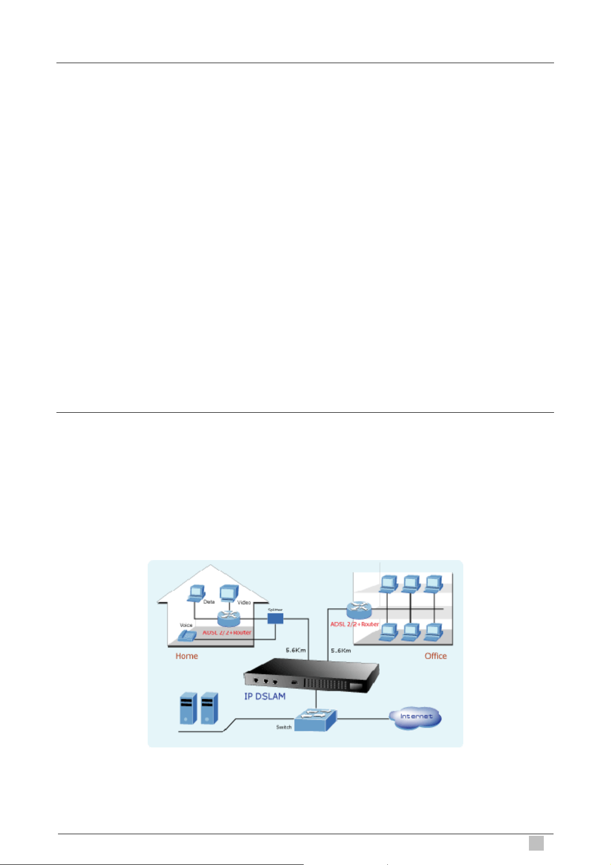
1.2 Features
z 24-Port or 48-Port ADSL/ADSL2/ADSL2+ subscriber interface with build-in POTS splitter
z DMT data rate: Downstream 32 kbps up to 25 Mbps / Upstream 32 kbps up to 1Mbps
z 1000Base-T (IDL-2400/IDL-4800) or 1000Base-LX (IDL-2401/IDL-4801) uplink interface
z Stackable support
z Microsoft Windows based GUI management
z Local RS-232 CLI and Ethernet SNMP/Telnet management
z Firmware upgradeable via FTP or TFTP
z 6K MAC address & 256 Multicast MAC address support
z Static VLAN and Port based VLAN
z VLAN / MAC / IP filtering
z Access Control List by MAC and IP address
z Traffic prioritization (802.1p)
z Traffic bandwidth management by MAC and IP address
1.3 Application
The PLANET IDL series offer the benefit of high performance to central office co-location
and MTU (Multi-Tenant Unit) / MDU (Multi-Dwelling Unit) markets. It provides broadband
data service over existing copper wires without affecting the conventional voice service by
24/48 subscriber ports with built-in POTS splitter. A PLANET IP DSLAM is the perfect
solution for NSP a cost-effective but high-value centrally management capability.
IP DSLAM
25
Page 26
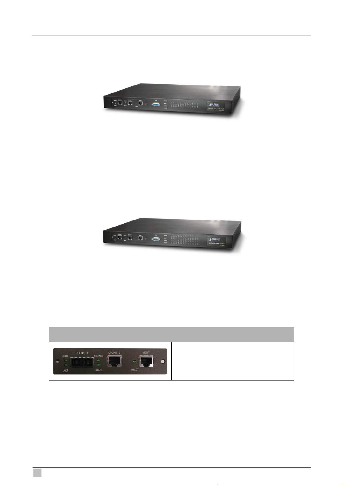
1.4 Outlook
IDL-2400
IDL-4800
IDL-2401 / IDL-4801 with 1000Base-LX UPLINK
1 x 1000Base-LX UPLINK1
1 x 1000Base-T UPLINK2
1 x 1000Base-T MGNT
26
IDL series User Guide
Page 27
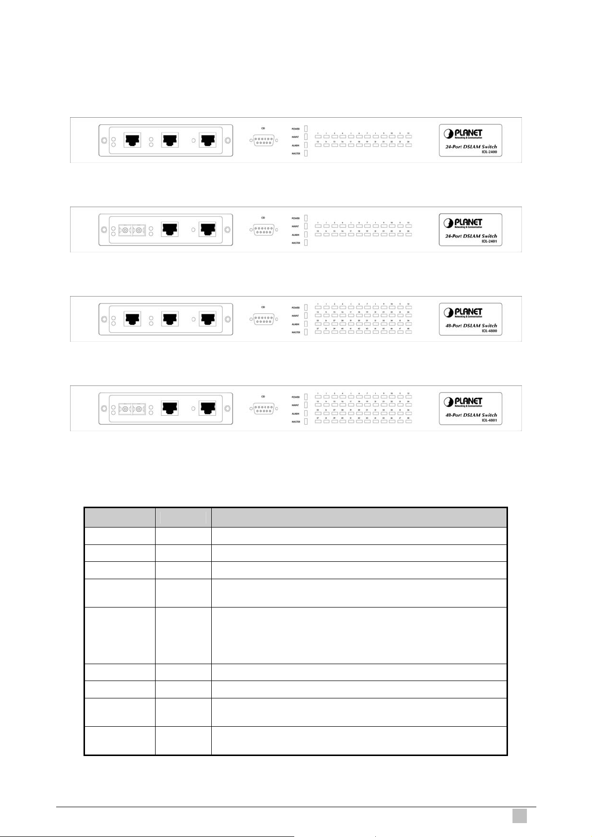
1.4.1 Front Panel
The front panels of IDL series are shown below.
IDL-2400
IDL-2401
IDL-4800
IDL-4801
LED Definition
LED Color LED Description
POWER Green Lit when power on
MAINT Yellow Lit when maintenance commands were issued
ALARM Red Lit when MJ/MN events happen
MASTER Green
ADSL 1~24
or
ADSL 1~48
Green
Orange
No Light
Red
Lit when system was acted as management master for
stacking application ( * Future feature )
Lit when ADSL link is in a active state
When the specified ADSL link is in connection training stat
When ADSL link is not in service
Lit when loss of signal occurs
IP DSLAM
1000/ACT Green Blinking when information action is transmitted
100/ACT Green Blinking when information is transmitted
GIGA Green
ACT Green
Blinking when information is transmitted
( * IDL-2401/4801 )
When uplink is activated
( * IDL-2401/4801 )
27
Page 28
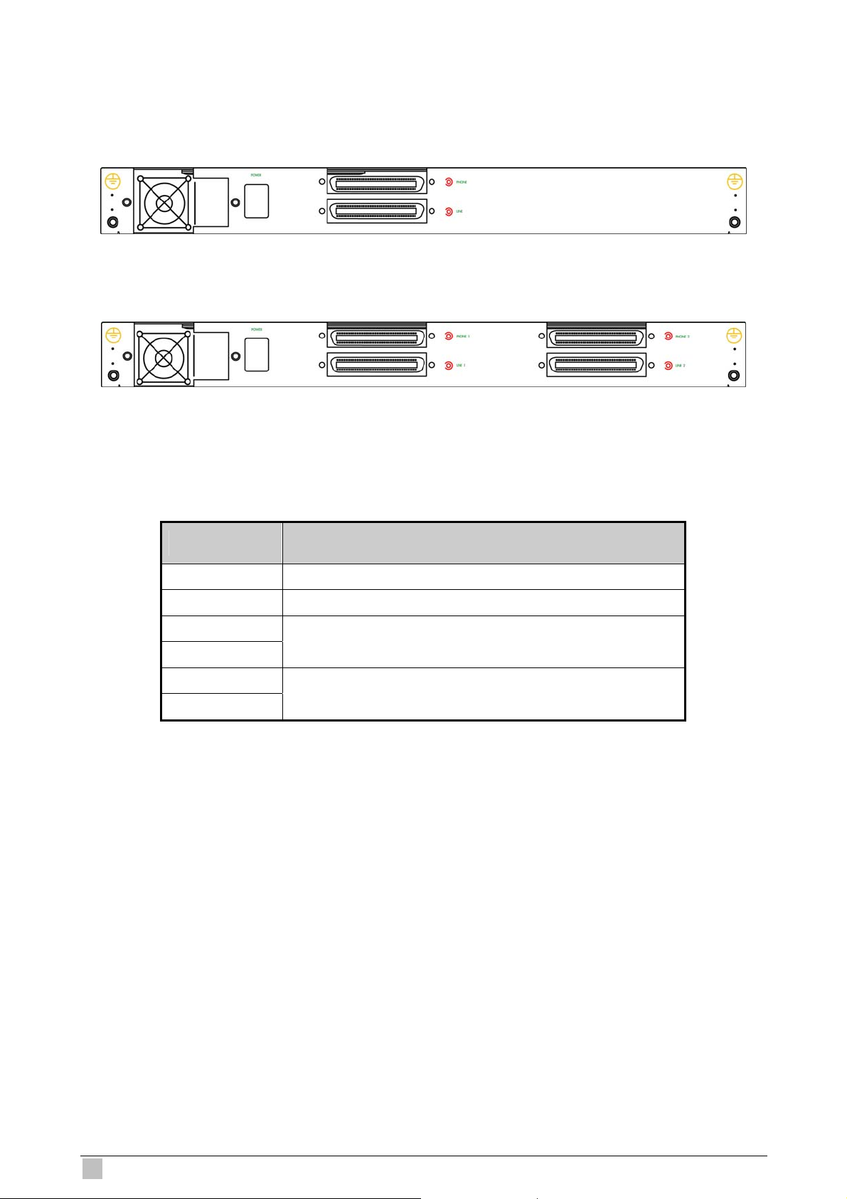
1.4.2 Rear Panel
The rear panels of IDL series are shown below.
IDL-2400/2401
IDL-4800/4801
Port Definition
Port Port Description
AC IN
POWER
PHONE 1
LINE 1
PHONE 2
LINE 2
AC Power cord in
Power switch
24 port ADSL module with built-in POTS
24 port ADSL module with built-in POTS
( * IDL-4800/4801 )
28
IDL series User Guide
Page 29

1.5 Technical Specifications
1.5.1 Hardware Specifications
Model IDL-2400 IDL-2401
Uplink 1 1 x RJ-45 (10/100/1000Base-T) 1 x SC (1000Base-LX)
Uplink 2 1 x RJ-45 (10/100/1000Base-T)
Ports
LED Indicators
MGNT 1 x RJ-45 (10/100/1000Base-T)
Console 1 x RS-232
Line 1 x Telco-50
Phone 1 x Telco-50
1 x POWER LED
1 x MAINT LED
1 x ALARM LED
1 x MASTER LED
24 x ADSL LEDs
2 x 1000/ACT LEDs
3 x 100/ACT LEDs
1 x POWER LED
1 x MAINT LED
1 x ALARM LED
1 x MASTER LED
24 x ADSL LEDs
1 x 1000/ACT LEDs
2 x 100/ACT LEDs
1 x GIGA LED
1 x ACT LED
Model IDL-4800 IDL-4801
Uplink 1 1 x RJ-45 (10/100/1000Base-T) 1 x SC (1000Base-LX)
Uplink 2 1 x RJ-45 (10/100/1000Base-T)
Ports
LED Indicators
MGNT 1 x RJ-45 (10/100/1000Base-T)
Console 1 x RS-232
Line 2 x Telco-50
Phone 2 x Telco-50
1 x POWER LED
1 x MAINT LED
1 x ALARM LED
1 x MASTER LED
48 x ADSL LEDs
2 x 1000/ACT LEDs
3 x 100/ACT LEDs
1 x POWER LED
1 x MAINT LED
1 x ALARM LED
1 x MASTER LED
48 x ADSL LEDs
1 x 1000/ACT LEDs
2 x 100/ACT LEDs
1 x GIGA LED
1 x ACT LED
IP DSLAM
29
Page 30

1.5.2 Software Specifications
Compliant with ADSL standard
- ANSI T1.413 issue 2
- G.dmt (ITU G.992.1)
- G.lite (ITU G.992.2)
Standard
Protocol
Multicast
- G.hs (ITU G.994.1)
Capable of ADSL2 standard
- G.dmt.bis (ITU G.992.3)
Capable of ADSL2+ standard
- G.dmt.bisplus (ITU G.992.5)
STP
IGMP snooping
GMRP
GVRP
LACP
SNMP / UDP / IP / MAC / Ethernet
Up to 256 multicast addresses
IGMP v1, v2, v3
Multicast VLAN mapping: Independent VLAN multicast (IVM)
Multicast VLAN mapping: Shared VLAN Multicast (SVM)
Handle PPPoE Encapsulated IGMP packets
Subscriber interface with built-in POTS splitter
System
Downstream DMT data rate 32 kbps up to 25 Mbps
Upstream DMT data rate 32 kbps up to 1Mbps
Extended power management capabilities to optimize power
consumption for each application
Distance up to 18 kft
1000Base-T / 1000Base-LX uplink interface via model
Stackable support
Centronic 50 pin connector for Telco line in and out
8 VCs per xDSL port
128 MAC address per x DSL port
6K MAC address
Ethernet Bridging: Broadcast, Flooding / Dropping
VLAN Bridging: 512 VLAN, Static VLAN, VLAN Stacking / Trunking
Packet size 64 byte to 1522byte
PPPoE Intermediate Agent
DHCP Relay Agent
IPOA to IPOE Tunneling
PPPoA to PPPoE inter-working
30
IDL series User Guide
Page 31

Security
Input Rate Limiting (IRL) on a per-AAL5 interface
Output Rate Limiting (ORL) on a per ATM-port and Ethernet basis
Rate Limiting
Multiple mechanisms of prioritizing traffic
VLAN filtering
MAC filtering
IP filtering
Access Control List by MAC address
Access Control List by IP address
Throttling Control
Sticky Bridge Ports
Microsoft Windows based GUI management
Local RS-232 CLI, and Ethernet SNMP / Telnet management
Management
Remote in-band SNMP / Telnet management
Firmware upgradeable via FTP or TFTP
SNMP v1, v2c
IP DSLAM
31
Page 32

2. Installation
The followings are instructions for setting up the IDL series IP DSLAM. Refer to the
illustration and follow the simple steps below to quickly install your IP DSLAM.
2.1 Safety Instruction
The following is the safety instructions for IP DSLAM before installing.
>> The maximum recommended operating temperature is 50ºC. Care must be taken to
allow sufficient air circulation or space between units when the IP DSLAM is installed
inside a closed rack assembly and racks should safely support the combined weight of all
IP DSLAM.
>> The connections and equipment that supply power to the IP DSLAM should be capable
of operating safely with the maximum power requirements of the IP DSLAM. In the event
of a power overload, the supply circuits and supply wiring should not become hazardous.
>> The AC power cord must plug into the right supply volt age. Make sure that the supplied
AC voltage is correct and stable. If the input AC voltage is over 10% lower than the
standard may cause the IP DSLAM to malfunction.
>> Generally, when installed after the final configuration, the product must comply with the
applicable safety standards and regulatory requirements of the country in which it is
installed. If necessary, consult for technical support.
>> A rare condition can create a voltage potential between the earth grounds of two or
more buildings. If products installed in separate building are interconnected, the voltage
potential can cause a hazardous condition. Consult a qualified electrical consultant to
determine whether or not this phenomenon exists and, if necessary, implement corrective
action before interconnecting the products. If the equipment is to be used with
telecommunications circuit, take the following precautions:
- Never install telephone wiring during a lightning storm.
- Never install telephone jacks in wet location unless the jack is specially - designed for
wet location.
- Never touch uninsulated telephone wires or terminals unless the telephone line has
been disconnected at the network interface.
- Use caution when installing or modifying telephone lines (other than a cordless
telephone) during an electrical storm. There is a remote risk of electric shock from
lightning.
- Do not use a telephone or other equipment connected to telephone lines to report a
gas leak in the vicinity of the leak.
32
IDL series User Guide
Page 33

2.2 Hardware Installation
The PLANET IDL series can be installed in a standard 19-inch rack by using the mounting
brackets provided. Mount the shelf on the rack using the large screws provided. The
procedure to connect and wire the system is as follows.
2.2.1 System Requirements
z Workstation with Windows NT/2000/XP
z RJ-45 cables
z RJ-11 cables
z Telco-50 cables
z RS-232 cables
z <Optional> MDF Patch Panel (Model No.: IDL-PAN-48).
2.2.2 Rear Panel Connection
The following figure shows the rear panel connection of IDL series:
Step 1: Ground the IP DSLAM by connecting a grounded wire (Optional).
Step 2: Connect the ADSL line connector, a 50-pin centronic connector, of IP DSLAM to
CPE by using telco cable. Each line connector supports 24 ports of
ADSL/ADSL2/ADSL2+ for Data path from MDF (Main Distribution Frame).
IP DSLAM
33
Page 34

Step 3: Connect the Phone connector, a 50-pin centronic connector, of IP DSLAM to
Exchange/PBX by using telco cable. Phone connector is an optional module
supporting Voic path to Exchange/PBX; it must be along with Line Connector.
Note:
1. The MDF Patch panel is optional to standard package.
Step 4: Hook power cord and apply the power.
2.2.3 Front Panel Connection
The following figure shows the front panel connection of IDL series:
UPLINK: Connect to Internet or downlink to the other IDL-series for stacking by RJ-45
cable.
MGNT: Connect to PC by RJ-45 cable in order to administer your IP DSLAM through IDL
Manager.
CID: Connect to PC by RS-232 cable in order to administer your IP DSLAM through CLI.
34
IDL series User Guide
Page 35

2.3 IDL Manager Installation
This following shows how to prepare the system to perform basic communication functions
through IDL Manager.
2.3.1 System Requirements
z Windows NT/2000/XP
z CD-ROM
z Ethernet card
z 2GB Hard disk with a minimum of 650MB of free space
z Super VGA (800x600 resolution) or higher with 256 colors
z Manual CD
2.3.2 Installing IDL Manager
Perform initial configuration procedures as follows:
1. Insert CD into CD-ROM.
2. From the autorun screen, click the “IDL Manager” hyperlink to download the file. And
then click “setup.exe” to start the installation process.
3. The welcome window appears. Click on “Next” to continue.
IP DSLAM
35
Page 36

4. When the Start Copying Files window appears, you can confirm the current settings.
Click on “Next” to start copying files.
5. When Setup Process Status window appears, the installation process is now in
progress. This window display a bar indicating the percentage of completion for the
current installation. In addition, the names of the files being installed appear above the
bar until the installation is complete.
6. At the end of the installation process, the following Setup Complete window presents.
Simply click on “Finish” to complete setup. Now the installation of IDL Manager is
completed.
36
IDL series User Guide
Page 37

2.3.3 Starting IDL Manager
Perform basic communication functions through IDL Manager, procedures as follows:
1. Users can activate the IDL Manager either from Program manager or clicking the
shortcut icon on the desktop as below.
2. Before starting to IDL Manager, it is necessary that your PC’s IP and IP DSLAM’s IP
are in the same subnet.
Note:
Default IP address of Management port is 192.168.200.111.
3. To enable SNMP for accessing, one needs to issue commands below to IDL series by
Telnet to management port or connecting to console port (9600, N, 8,1) and then log in
with default username and password that both are “admin”.
a. “$create snmp comm community public rw”.
b. “$create snmp host ip 192.168.200. xxx community public”, where 192.168.200.xxx
is the IP of your PC.
c. “$create snmp traphost ip 192.168.200.xxx community public version v1”, where
192.168.200.xxx is the IP of your PC.
4. Launch the IDL Manager and then log in with the user name and password.
Click on “OK” to enter the IDL Manager system.
Note:
Default Username is “Supervisor” and password is blank.
5. After launching IDL Manager and logging in, the main window appears as below.
IP DSLAM
37
Page 38

2.4 IDL Manager Functions
IDL Manager is divided into the task-oriented functional groups as follows.
2.4.1 Session
Allow you to start and to terminate a session as well as to shutdown the system.
2.4.1.1 Logout
To terminate the current session, choose Logout command from Session Menu. The
user account, then, is logged out and Login window prompts for a new login. Normally,
this is used when a user wants to re-login in order to gain a higher level of authority for
certain operations.
2.4.1.2 Exit
To terminate the system at any time, simply choose the Exit command from Session
Menu. The system then terminates.
38
IDL series User Guide
Page 39

2.4.2 Tools
This chapter describes how to use tools in the IDL Manager, including Environmental
options, Territory manager, Agent manager, User Manager and Telnet, which are detailed
in the following sections.
2.4.2.1 Environment Options
Choose Environmental Options from Tools Menu, user can define SNMP, Desktop
and Surveillance respectively.
1. SNMP Configuration
The SNMP Time-out Period and Retransmission times can be configured as shown in
the following steps:
a. Click on the TabControl of “SNMP” that will bring SNMP dialogue box to front.
b. Click on / to change the Time-out Period seconds and Retransmission
times.
c. Click on to submit your changes.
2. Desktop Configuration
IP DSLAM
39
Page 40

The Desktop is user for setting the map of a required territory.
a. Click on the tab of “Desktop” that will bring Desktop dialogue box to front.
b. Click on to quick start territory manager in which users can
define a desired territory. Please refer to “Territory Manager Configuration” for
more details.
c. Click on to load the map of a territory or click on to clear a
loaded map.
Note:
The format of map is limited to *.bmp, *.emf and *.wmf.
d. Click on to submit your setting, and then the map will apply to the
Mounted Agent.
3. Surveillance Configuration
40
IDL series User Guide
Page 41

a. Click on the tab of “Surveillance” that will bring the Surveillance dialogue box to
front.
b. Click on
or to change the monitor period.
c. Select the checkbox of Save expired records to save surveillance archive,
which can be browsed by clicking on the tab of Achieved in the Event Log
window as shown in the following figure.
IP DSLAM
d. Clicking on to choose the directory to record surveillance data and
press or to define expired period.
e. Click on to submit your settings.
41
Page 42

2.4.2.2 Territory Manager
Territory manager help users to build up monitoring territories and agents could be
categorized into different territories by users. Territory manager can be activated
either from menu bar or from environmental options.
Territory Manager Window
Choose Territory Manager via Tools Menu, or Environmental option, and then the Territory
Management window appears.
If to add a territory to the system,
a. Click on , the Territory Name fields then cleared to blank for entering
the data.
b. Enter Territory Name and then become enable.
c. Click on to apply the territory to the system. After that, you can proceed to
group management by Territory Management dialog box.
As the following figure shown, the agent, 192.168.100.176 is available in the territory named
ALL on the left. Users can shift the monitoring territory from ALL to Taipei simply by selecting
Taipei in the Drop-down list on the right.
42
IDL series User Guide
Page 43

d. Choose the agent, 192.168.100.176 on the left and then click on . The agent IP
will appear on the right and will be mornitored under the territory, Taipei.
e. If users want to move the agent IP from Taipei to other territory, select a desired agent
IP and click on
to shift it to the left.
f. Click on
same window.
Correspondently, the Agent Desktop displays that Agent IP 192.168.100.176 has been
monitored under the territory, Taipei.
to exit the window or continue to perform other operations in the
IP DSLAM
43
Page 44

2.4.2.3 Agent Manager
All of the IP DSLAM agents that are to be managed by the IDL Manager must be
“registered” to the system. The “registration” process is to make the system aware of
agent’s IP address and alias name. Once an agent is registered, it is put into the
“demount” agent pool, which is still “inactive” for the network monitor. You then have
to activate it if you want it to be monitored. An active agent can also be deactivated
from the monitor for certain operational purpose when necessary. Agent Manager is
designed for you to perform these operations.
Agent Manager Window
Choose Agent Manager from Tools Menu, this window then appears.
Field Definition
IP Address ***.***.***.***
Alias name Name of IP DSLAM
Description Note
If to add an agent to the system,
a. Select a territory that a new agent belongs to. Click on
activate territory manager.
b. Click on
, the data fields then cleared to blank for entering the data.
Enter values in fields, IP Address, Alias Name and Description. The Apply
buttons to the left of these fields then become enable.
c. Click on to apply the agent to the system.
d. If to activate (so-called “Mount”) the system’s monitoring of an agent, click on
the required agent entry in the Demount agent list, then click on . The
agent will appear on the Mount agent list on the right.
to
e. Click on to exit the window or continue to perform other operations.
44
IDL series User Guide
Page 45

If to remove an agent to the system,
a. Click the required agent in the Demount agent list, and then click on
The agent will disappear.
b. Click on
to exit the window or continue to perform other operations
in the same window.
If to change the information of an agent,
a. Select the required agent in the Demount agent list. The information of the
selected agent will then presented on the data fields.
b. Click on to Change IP, Alias Name, and Description and then
becomes enable.
c. Click on
to apply the change to the system.
d. Click on
to exit the window.
.
Note:
User can only change alias and description of the agent in the Mount agent list and
changing IP is prohibited.
If to activate the system’s monitoring of an agent,
a. Select the required agent in the Demount agent list, and then click on the Mount
button . The agent will appear on the Mount agent list.
b. Click on
to exit the window or continue to perform other operations
in the same window.
If to de-activate the system’s monitoring of an agent,
a. Select the required agent in the Mount agent list, and then click on the Demount
button
. The agent will then disappears from the Mount agent list and
appears on the Demount agent list on the left.
IP DSLAM
b. Click on to exit the window.
45
Page 46

2.4.2.4 Telnet
Users can use the Telnet to connect to a specific IP DSLAM, and then monitor and
interact with the system.
How to activate Telnet from Agent Desktop?
a. Select an agent IP on the Agent desktop.
b. Click on the right button of mouse and then select Telnet or choose Telnet from
tool menu in the IDL Manager window’s menu bar. Then Telnet screen will
come up immediately.
Enter user name and password to access the CID screen.
c.
Note:
The default login and password are admin.
46
IDL series User Guide
Page 47

2.4.2.5 PING
Ping is a command used to determine whether a particular IP DSLAM is currently
connected to the agent. It works by sending a packet to the specific IP address and
waiting for reply.
How to activate PING from Agent Desktop?
a. Select an agent IP on the Agent desktop.
b. Click on the right button of mouse and then select Ping or choose it from tool
menu in the IDL Manager window’s menu bar. Ping screen will come up
immediately and then starts to send packets to check the connection with the IP
DSLAM.
c. After showing the connection status, the screen will be closed automatically.
IP DSLAM
47
Page 48

2.4.2.6 User Manager
The IDL Manager uses user accounts, password as well as power level (system
privileges) to control access and log in. There are three types of privileges, Supervisor,
Constructor and Tester.
Supervisor:
The highest level user with this privilege can access ANY functions and data.
Constructor:
User can set and modify the configuration of network equipments.
Tester:
User can run maintenance test, such as loop back function.
To perform user manager, proceed as follows,
Choose User Manager from Tools Menu to access this window. From the following
window, User Manager, you can add and remove users as well as change passwords,
which are used to control the login.
Field Definition
User Account an ID to be used for login
User Name The full name of a user
Description Remarks for note purpose
Power Level Privileges; Administrator and Tester
48
IDL series User Guide
Page 49

If to add a User Account to the system,
a. Click on
, the Security window then prompts.
b. Enter the account information as described in Security window below.
c. Click on
to exit the window or continue to perform other operations.
If to remove a User Account from the system,
a. Select a user account by clicking on the desired entry in User Account selection
list. After selection, the designated one will be highlighted.
b. Click on
to delete it.
c. Click on
to exit the window or continue to perform other operations.
If to change User Account information,
a. Select a user account by clicking on the desired entry in User Account selection
list. After selection, the designated one will be highlighted.
b. Click on button, the Security window then prompts.
c. Change the account information as described in Security window below.
d. Click on button to exit the window or continue to perform other
operations. Or click on
button, the Security window then prompts.
IP DSLAM
49
Page 50

Field Definition
User Account An ID to be used for login
User Name The full name of a user
Description Remark for note purpose
Password Any character string, including blank
Verify Password Re-enter the password as a confirmation
To change password
when next login
Account Suspended Suspend the account.
Power Level Privileges; Administrator and tester
If this is checked, the associated user needs to change
their password at the next login.
This window is a daughter window of User Manager Window, and is used when
adding a user account or changing account information.
a. Either
or is selected, this window appears.
b. Enter data in the fields, User Account, User Name, Description, and Password
as required. Re-enter the password in field, Verify Password, for purpose of
verification.
c. If to force the user to change their password at the next login, click on the
checkbox to the left of the field, To Change Password When Login Next Time.
d. If to suspend a user account, click on the checkbox to the left of the field,
Account Suspended.
e. If to assign a new Power Level to the user, click on the desired entry in the
Demount list, then click on the Mount button, . The selected Power
Level entry will then be added to the Mount list on the right.
f. If to remove a Power Level from the user, click on the desired entry in the Mount
list on the right, then click on the Demount button,
. The selected
Power Level entry will then be removed.
g. Click on to complete the operation or to abort the
change. Either one is selected; the window is exited to User Manager Window.
50
IDL series User Guide
Page 51

2.4.3 Windows
Users may open many daughter windows in the IDL Manager. To benefit user’s viewing
every Window, Commands of the Windows menu is designed to arrange daughter windows.
Those commands will be introduced separately.
2.4.3.1 Cascade
Choose Cascade from Windows menu in the IDL Manager menu bar. The cascade
command can cascade those opened windows as follows. User can select a window
to perform operations or view status simply by clicking on a specified window.
2.4.3.2 Next Window
Next Window helps user to view next window so that it will bring the window in the
second layer to front.
2.4.3.3 Previous Window
Previous Window command can help user to bring the previous window to front.
IP DSLAM
51
Page 52

2.4.3.4 Arrange Icons
By selecting Arrange Icons of Windows Menu in the menu bar, it will locate those
minimized daughter windows in the bottom left of IDL Manager Window as the
following figure shown. User can select a required icon to perform IDL Manager
Management.
2.4.4 Help
Allow users to view the software version.
2.4.4.1 About
To view the version of IDL Manager, choose “About” command via Help menu, as
shown in the following figure. Click on
to exit the window.
52
IDL series User Guide
Page 53

3. IDL Manager Management
After successfully setting up the environment of IDL Manager, you can manage different IP
DSLAM via your IDL Manager remotely. This chapter will tell you how to interact with a
specified IP DSLAM.
3.1 Agent Desktop
Agent Desktop is the main window for the network administrators in performing their
day-to-day network monitoring jobs. Like the standard desktop of MS Windows, Agent
Desktop appears once the system is started. First appears on the Agent Desktop is the
status of agents by an array of colors. By which you may monitor the status of agents, and
judge if they are normal or in situations of alarms. You may then double click on the
required agent IP to activate the event log window. Similarly, the Mounted Agents Desktop
can be started up by double clicking on the icon of territory.
3.1.1 Agent Desktop Window
In the Agents Desktop, press to refresh the status of all agents.
Gray icon indicates that the agent is disconnected.
Green icon indicates that the agent is in normal condition.
Red icon indicates that “Major Alarm” is occurred to the
agent and requires network administrator’s attention.
Network administrator pays attention to alarms by looking
into the alarms using Event Log – Outstanding.
The red icon will turn into a yellow icon after the network
administrator has looked into the alarms. However, this
does not mean the situation is released. If any new alarm
IP DSLAM
happens, yellow will turn red.
Black icon indicated that the agent is demounted.
53
Page 54

3.1.2 Mounted Agent Desktop
Mounted agent desktop provides users with flexibility in viewing your network using
graphical presentation of network elements. Mounted agent desktop can be easily activated
by double clicking the icon of territory in the agent desktop and appears promptly as shown
in the following figure. By the mounted agent desktop, the location of agents and overall
network status of a specific territory is presented.
: This icon can be moved to where the agent is located in the map. In addition, its
color also changes with the status of the agent. For example, the icon in red means that
alarm is occurred to the agent and requires network administrator’s attention.
54
IDL series User Guide
Page 55

3.2 Active Function Management Windows
Via IDL Manager, users can remotely monitor the current status of a specified IP DSLAM,
and then proceeding advanced configuration. To activate the function management
windows, choose a specified agent that you want to manage, and then double click the
agent. After that, the function management windows, including Function window and Front
panel status window, will prompt as shown in the following figure.
The Function management windows include Function List Window and Front Panel Status
Window which are provided to monitor the status in real time and configure related settings.
3.2.1 Function List Window
From the Function List Window, users can activate a specified function
immediately by double clicking a specified item.
IP DSLAM
55
Page 56

3.2.2 Front Panel Status Window
After choosing a specified agent, the Front Panel Status Window, together with the
Function Window, will come out immediately to present the current status of front panel of
the IP DSLAM.
3.3 Default Setting
This section describes how to get the information of the default setting of the IP DSLAM.
Click on “Default Setting” from the Function List window. The window appears as follows.
In the default setting window, the status of, IP, System, VCC connection, DSL line profile
and Alarm profile are displayed clearly. How to modify them will be introduced in the
following sections.
56
IDL series User Guide
Page 57

3.4 System Information
This section describes how to get and input the information of the IP DSLAM. Double Click
on “System Information” from the Function List Window. The window appears as follows.
Field Definition
Name Alias name of the IP DSLAM
Location Location of the IP DSLAM
Contact The contact person of the IP DSLAM
Vendor The vendor of the IP DSLAM
Object ID Vendor ID
DST Daylight Savings Time has been enabled or not.
UpTime System up time
HwVersion Hardware version of the IP DSLAM.
CPSwVersion Control plant version
The severity level of the trap equal to or lower than that shall be logged.
Log Threshold
Time Zone
Current Time The current time.
0 represents log threshold is disabled. 1 is the lowest and represents critical
traps. Valid values: 0-4
Valid values: Given below, are the valid values, followed by their descriptions.
IDLW - International Date Line West
NT - Nome
HST - Hawaii Standard
CAT - Central Alaska
AHST- Alaska-Hawaii Standard
YST - Yukon Standard
PST- US Pacific Standard
MST- US Mountain Standard
CST- US Central Standard
EST- US Eastern Standard
AST- Atlantic Standard
NFST- Newfoundland Standard
NFT- Newfoundland
BRST-Brazil Standard
A T- Azores
WAT - West Africa
GMT - Greenwich Mean
UTC - Universal (Coordinated)
WET - Western European
CET - Central European
FWT - French Winter
MET - Middle European
MEWT - Middle European Winter
SWT - Swedish Winter
EET - Eastern Europe, Russia Zone 1
IST - Israeli Standard
BT - Baghdad, Russia Zone 2
IT - Iran
ZP4 - "Russia Zone 3"
ZP5 - "Russia Zone 4"
INST - "Indian Standard"
ZP6 - "Russia Zone 5"
NST - "North Sumatra"
WAST - West Australian Standard
SSMT - South Sumatra, Russia Zone 6
JT- Java
CCT - China Coast, Russia Zone 7
ROK - Korean Standard
KST - Korean Standard
JST - Japan Standard, Russia Zone 8
CAST - Central Australian Standard
EAST - Eastern Australian Standard
GST - Guam Standard, Russia Zone 9
IDLE - International Date Line East
NZST - New Zealand Standard
NZT - New Zealand
Example: IDLW , that stands for
International Date Line West
IP DSLAM
57
Page 58

3.5 Current Event
Describes the facility for the network administrators to track and trace the history of events
happened and released. Current Event window can be activated from Function List Window.
There are three daughter windows provided to accomplish above tasks.
3.5.1 Outstanding Event
Allow you to view the outstanding events or status and system information. If to view the
event log of a specific agent, click “Current Event” from Function List Window. The Event
Log window appears as follow.
Field Description
Happen Time The date/time when the event is occurred.
Agent The IP address of the agent associated
Grade Severity level of event or status.
DSL DSL Port
Site Down stream or upstream
Description The description of the event or status.
58
IDL series User Guide
Page 59

3.5.2 Closed Event
This window allows you to browse the closed alarms and events of specified agents. Click
on the tab of “Closed“, that will bring the closed screen to front as the following figure
shown. Click on to clear all records or to exit the window.
Field Description
Happen Time The date/time when the event is occurred.
Release Time The date/time when the event is closed.
Agent The IP address of the agent associated
Grade Severity level of event or status.
DSL DSL Port
Site Down stream or upstream
Description The description of the event or status.
IP DSLAM
59
Page 60

3.5.3 Archived
This window allows you to browse the expired records, which can be configured in the
Environment window. Click on the tab of “Archived“, that will bring the archived screen to
front as the following figure shown. Click on to clear all records or to
exit the window.
Field Description
Happen Time The date/time when the event is occurred.
Release Time The date/time when the event is closed.
Agent The IP address of the agent associated
Grade Severity level of event or status.
DSL DSL Port
Site Down stream or upstream
Description The description of the event or status.
60
IDL series User Guide
Page 61

3.6 System
This section allows users to perform commit and reboot that will be introduced as follows.
3.6.1 Commit and Reboot
This section describes how to commit the current configuration to flash or reboot the IP
DSLAM. Double Click on “Commit and Reboot” from the Function List Window. The
System Information screen appears as follows.
a. If to commit the active configuration to the flash, click on .
b. If to reboot the system and to set the boot configuration, click on
c. Click on to close the window.
.
IP DSLAM
61
Page 62

3.7 Configuration
This section describes how to configure the IP DSLAM by selecting Configuration from
Function List window.
3.7.1 VLAN
Allow user to view and modify VLAN configuration. Double Click on “VLAN” from the
Function List Window. The VLAN configuration window appears as follows.
Field Definition
The VLAN id for this VLAN. In devices supporting
"Shared Vlan for multicast" capability, the information for
a multicast mac addr is shared across vlans hence vlan id
VLAN ID
VLAN Name Name of the VLAN
Egress PVC
Untagged PVC
is an optional parameter. In devices supporting
"Independent Vlan for multicast" capability each vlan can
have its own information for a multicast mac addr hence
vlanid is a mandatory parameter in all the commands
other than - get. For No Vlan case vlan id is not required.
The set of ports, which are permanently assigned to the
egress list for this VLAN by management.
The set of ports, which should transmit egress packets for
this VLAN, as untagged.
62
IDL series User Guide
Page 63

a. Select the VLAN to view or modify by using the VLAN ID drop-down list.
b. Use Egress PVC and Untagged PVC drop-down list to set the specified DSL port’s
Egress PVC and Untagged PVC.
c. Click on to submit your settings or click on to close the VLAN
Configuration window.
3.7.2 Ethernet
Allow user to view and modify Ethernet configuration. Double Click on “Ethernet” from the
Function List Window. The Ethernet Configuration window appears as follows.
Field Definition
DHCP DHCP client enabled or disabled
Type Uplink or Downlink
Admin Status The desired state of UPLINK (enable/disable)
Operation Status System is enabled or not.
IP address IP address of the UPLINK
Mask The network mask of the UPLINK.
Gateway Gateway IP
VLAN for management traffic on this interface. Nonzero value
of this field is valid only if either 'ip' field is non-zero or 'usedhcp'
field is true. If no Management Vlanid is specified (in the create
operation) or its value is set to zero (either in create or modify
operation) then the system shall use the value of 'portvlanid'
Mgmt Vlan Index
associated with the bridge port created on this interface as the
Management Vlan Index. In case the management vlan (i.e.
'mgmtvlanid' or the associated 'portvlanid', if 'mgmtvlanid' is
zero) doesn't exist on the system then management shall not
happen on this interface till the corresponding VLAN is created
with the Net side port as its member.
IP DSLAM
63
Page 64

a. To view the Ethernet Configuration of UPLINK1, UPLINK2, or MGNT by using the
Select Ethernet drop-down list.
b. If to modify the Ethernet Configuration, click on first and then proceeding
advanced configurations as shown in the following figure.
c. If to create a new Ethernet configuration, click on and then select a new
Ethernet configuration by using Select Ethernet drop-down list. After that, users can
set related parameters as follows.
d. Click on
to submit your settings or click on to close the Ethernet
Configuration window.
64
IDL series User Guide
Page 65

3.8 DSL
This section describes how to configure DSL settings by selecting DSL from Function List
Window.
3.8.1 Profile
Allow users to configure Line Profile and Alarm Profile.
3.8.1.1 Line Profile
If to configure Line Profile, double click on “Line Profile” from the Function List
Window. The Line Profile configuration window appears.
Field Definition
Line Type The ADSL line type, Fast or Interleaved.
Transmit Rate Mode Defines what form of transmitting rate, Fixed or adaptAtStartup.
Target SNR (dB/10) Target Signal / Noise Margin. (0-310).
Min Tx Rate(bps) The minimum transmitting rate of ATU-C side or ATU-R side.
Configured Signal/ Noise Margin for rate downshift. If the noise margin
Down Shift SNR (dB/10)
IntCorrectionUP
Preferred Standard
Maximum Transmit Rate The maximum transmitting rate of ATU-C side or ATU-R side.
Interleave Delay (ms) The value of Interleave Delay for this channel.
UP Shift SNR (dB/10)
IntCorrectionDown
Annex Type
falls below this level, the modem should attempt to decrease its transmit
rate. In the case that RADSL mode is not present, the value will be 0.
Sets the correction time for the upstream interleaved buffer. RS can also
be disabled.
Preferred standard compliance. Outcome is dependent
upon standard support of the remote unit. GlobespanVirata High Speed
ADSL DMT (ADSL+) application s only.
Configured Signal/ Noise Margin for rate upshift. If the noise margin rises
above this level, the modem should attempt to increase its transmit rate.
In the case that RADSL is not present, the value will be 0.
This parameter sets the correction time for the downstream interleaved
buffer. RS can also be disabled.
This parameter is set as per Annex compliance of the code release.
GlobespanVirata High Speed ADSL DMT (ADSL+) applications only.
IP DSLAM
65
Page 66

a. To create up a new line profile, click the DSL Name drop-down list and then
select the blank.
b. After that, the fields become enable. Input the values in those fields and then
name the new line profile.
c. Click on to submit your setting or click on to delete a line
profile.
3.8.1.2 Alarm Profile
If to configure Alarm Profile, double click on “Alarm Profile” from the Function List
Window. The Alarm Profile Configuration window appears.
66
IDL series User Guide
Page 67

Field Definition
Loss of frame within 15 minutes
The threshold of the number of “Loss of Frame Seconds”
within 15 minutes performance data collection period.
Loss of signal within 15 minutes
Loss of link within 15 minutes
Loss of power within 15 minutes
Errored seconds
The threshold of the number of “Loss of Signal Seconds”
within 15 minutes performance data collection period.
The threshold of the number of “Loss of Link Seconds”
within 15 minutes performance data collection period.
(But only ATU-C side)
The threshold of the number of “Loss of Power Seconds”
within 15 minutes performance data collection period.
The threshold of the number of “Errored Seconds” within
15 minutes performance data collection period.
a. To create a new alarm profile, click the DSL Name drop-down list and then
select the blank.
b. After that, the fields become enable. Input the values in those fields and then
name the new alarm profile.
c. Click on to submit or click on to delete a alarm profile.
3.8.1.3 All Line Profile
Display all the Line Profile Configuration.
3.8.2 Port Config
Allow users to configure port configuration. Double Click on “Port Config” from the
Function List Window. The Port Configuration window appears.
IP DSLAM
67
Page 68

Field Definition
DSL Port Port No. of the IP DSLAM
VPI Virtual Path Identifier
VCI Virtual Channel Identifier
The state of learning on this bridge port. The value enable (1)
Learning Status
Sticky Status
Pvid Port VID
Accepted Frame Type Used to up/down connection.
Ingress Filter
Priority Optional Connection priority. No VLAN tag, no priority.
indicates that unicast Mac address learning is enabled and the
value disable indicates that unicast Mac address learning is
disabled on this bridge port.
Indicates if the port has been set as sticky. The value enable (1)
indicates that the entries learned on this port will not be aged out.
It also indicates that the entries learned on this port shall not be
learned on any other port. The entries learned on this port can
only be removed by management action or by making the value
as disable (2), so that the entries can be aged out.
When this is true, the device will discard incoming frames for
VLANs, which do not include this Port in its Member set. When
false, the port will accept all incoming frames.
a. Choose the port to configure from the DSL Port drop-down list.
b. Configure the Administration status as “Up” or “Down”.
c. Choose a Line Profile from the Line Profile Name drop-down list. If to configure a
Line Profile, Click on to activate the Line Profile Configuration window.
d. Choose an Alarm Profile from the Alarm Profile Name drop-down list. If to configure
an Alarm Profile, Click on to activate the Alarm Profile Configuration window.
If necessary, modify values of specified PVC, including VPI, VCI, Admin Status, Learning
Status, Sticky Status, Pvid, Accepted Frame Type and Ingress Filter, and priority.
e. Click on to submit or click on to close the fmBridgeport window.
f. If to create new PVC, click on and then PVC2 appears and then users can
set perimeters via PVC2. after that, click on to submit your setting.
68
IDL series User Guide
Page 69

IP DSLAM
69
Page 70

3.9 DSL PM
This section describes how to utilize DSL Performance Management by selecting “DSL
PM” from Function List window.
3.9.1 Physical Layer Info
Allow users to view the physical layer information of a specified DSL port from the IP
DSLAM. Double Click on “Physical Layer Info” from the Function List Window. The
Physical Layer Info window appears.
Field Definition
SNR margin Noise margin value. (dB)
Attenuation
Status Current status of the ATU line.
output power Total output power transmitted by atu. (dBm)
attainable rate The maximum currently attainable data rate by the atu. (kbps)
ActualStandard
Bert Error Provides the number of bit errors detected during BER T.
TxAtm CellCt Provides Tx ATM cell counter.
RxAtm CellCt Provides Rx ATM cell counter .
Start Progress
Idle Bert Error Number of bit errors.
Idle Bert Cells Number of idle cells.
Difference in the total power transmitted and the tot al power received by the peer
atu. (db)
Actual standard used for connection, based on the outcome of the negotiation
with the Remote Unit.
Defines the current detailed start up state of Xcvr.
0x0 – startup not in progress; 0x0 – 0x0FFF Handshake/Training/ Profile
Management/ Fast Retrain in progress; 0x8000 – 0x8FFF DSP firmware DownLoad in progress; 0xF000 – 0xFFFF illegal Parameter
70
IDL series User Guide
Page 71

Bert Sync Indicates whether the Signal is in Sync or not.
Select Information Valid Indicates the information validity for the SELT operation conducted on the Xcvr.
Select Loop Length
Select Loop End
Select Loop Gauge
Indicates the LOOP Length in Feet once when the SELT information is valid on
the Xcvr.
Indicates whether the loop is short or open once when the SELT information is
valid on the Xcvr.
Indicates the LOOP wire gauge information on ce, when the SELT information is
valid on the Xcvr.
Select the port ID from the DSL Port drop-down list to view a specified DSL’s physical Layer
Info. Click on to close the window.
3.9.2 Channel Layer Info
Allow users to view the Channel layer information of a specified DSL port from the IP
DSLAM. Double Click on “Channel Layer Info” from the Function List Window. The
Channel Layer Info window appears.
Field Definition
Interleave delay Interleave delay for this channel. (milli-seconds)
Previous TX rate Previous actual transmit rate on this channel if ADSL loop retain. (kbps)
Current TX rate Actual transmit rate on this channel. (kbps)
CRC block length The length of the channel data-block on which the CRC operates.
Current Atm Status Indicates the current ATM Status.
Rs Symbols
Rs Depth Indicates interleaving depth (D), in the downstream direction.
Rs Redundency
Indicates the number of DMT symbols per Reed-Solomon code word (S),
in the downstream direction.
Indicates the number of redundant bytes (R), per Reed-Solomon code in
the downstream direction
Select the port ID from the DSL Port drop-down list view a specified DSL’s channel Layer
Info. Click on to close the window.
IP DSLAM
71
Page 72

4. Application Note
4.1 Basic Configuration
The IP DSLAM provides multiple services to users according to the demand of application
scenarios. To reduce time consuming in deployment, this document provides simple and
easy configuration procedure according different applications.
4.1.1 Create a new user
Users can create a root user whose user name and password are “admin” as follow.
$create user name admin passwd admin root
Entry Created
Privilege UserName
----------------------------------admin admin
Verbose Mode Off
Entry Created
$
4.1.2 FD.cfg Configuration
Fd.cfg is a useful tool that contains a set of default configuration commands for IP DSLAM.
Using FD.cfg, you can do as follow.
z Restore the default configuration
z Modify FD.cfg
z Upload FD.cfg
z Create new services
72
IDL series User Guide
Page 73

4.1.2.1 Contents of FD.cfg
Use WordPad or Word to open FD.cfg. (See the following figure)
The default configuration in FD.cfg summarized as follows.
z Default IP: 192.168.100.111
z SNTP: disable
z RFC-1483 Bridge mode only
z One PVC (8/81) for each ADSL port
z Bridge port numbering 1 to 48 mapping to PVC 8/81 for ADSL port1 to port 48/24
z VLAN feature Disable
z Eth0 enable (for uplink), its bridge port number is 385
z Eth1 disable (for downlink)
z MGMT interface disable
Note:
To view the detailed contents, please refer to the Appendix A.
IP DSLAM
73
Page 74

4.1.2.2 Download procedure
This section describes how to upload FD.cfg to IP DSLAM by tftp server. The
configuration procedure is shown as follows.
Step 1:
Prepare FD.cfg and tftp server. (Including file_id.diz, tftpd32.exe;TFTPD32.HLP
and uninst.exe)
Step 2:
Put the “FD.cfg” and “tftpd32” at the same folder on your PC.
Step 3:
Activate tftpd32 and then tftp32 window appears.
Step 4:
Click on
to set the current directory where FD.cfg located.
Step 5:
Click Sever interface drop-down list to select the DHCP Server‘s IP.
74
IDL series User Guide
Page 75

Step 6:
Assign an IP pool starting address.
Step 7:
Rename the boot file as FD.cfg.
Step 8:
Input the mask
Step 9:
Save the configuration.
Step 10:
If needed, click the settings button to re-configure your setting.
IP DSLAM
Step 11:
Activate Telnet and login IP DSLAM.
75
Page 76

Step 12:
Input ‘list’ to show the path and s/w information
$list
Name Ver Time Size
Acc State
-----------------------------------------------------------------------------------------------------------------/nvram/bin/bootptftp/
TftpBootp.bin 1 Wed Jun 30 14:12:36 2004 111064 RO active
/nvram/bin/control/
CP.bin.gz 1 Wed Jun 30 14:12:36 2004 1280744 RW active
/nvram/bin/dataplane/
DP.bin.gz 1 Wed Jun 30 14:12:36 2004 231572 RW active
/nvram/bin/decompressor/
Decompressor.bin 1 Wed Jun 30 14:12:36 2004 81928 RO active
/nvram/bin/dslphy/
gsv_dsl_AD_DM_3C00000C.bin.gz 1 Wed Jun 30 14:12:36 2004 155220 RW active
/nvram/cfg/factorydef/
FD.cfg 1 Wed Jun 30 14:12:36 2004 19136 RW active
Note:
$
Step 13:
Input ‘remove fname /nvram/cfg/factorydef/FD.cfg version 1’ to remove the
obsolete FD.cfg file.
$remove fname /nvram/cfg/factorydef/FD.cfg version 1
FLASH program starts at ADDR 20008
File Removed
$
Step 14:
Input ‘download src FD.cfg dest /nvram/cfg/factorydef/FD.cfg ip 192.168.100.66’ to
download config file “fd.cfg” from Server PC to IP DSLAM.
The file name to download could be different from FD.cfg but do not change the path.
dest /nvram/cfg/factorydef/FD.cfg is the path of firmware file located on IP DSLAM.
76
IDL series User Guide
Page 77

$download src FD.cfg dest /nvram/cfg/factorydef/FD.cfg ip 192.168.100.66
Downloading the File...
......................................
Block 1 erase in progress
........Flash block 1 erase successful...
FLASH program starts at ADDR 20000
###############
Step 15:
Input ‘upgrade fname /nvram/cfg/factorydef/FD.cfg’ to upgrade and activate the
access state.
$upgrade fname /nvram/cfg/factorydef/FD.cfg version 2
FLASH program starts at ADDR 2000c
$
Step 16:
Input ‘commit’ to store your new configuration before rebooting.
$commit
Step 17:
Input ‘reboot config default’ to let your new configuration take effect.
$reboot config default
IP DSLAM
77
Page 78

4.1.3 How to create myconfig.cfg
z myconfig.cfg is a txt file that ensures all commands be executed at once.
z 4.1.3.3 shows the format of myconfig.cfg.
z If there are many configurations you would like to execute then you can write all
commands into myconfig.cfg and then execute it at once.
z Be note to save ($commit) to IP DSLAM if this would be executed after rebooting.
z Required of equipment: TFTP Server (Tftpd32).
4.1.3.1 TFTP Server Configuration
Step Image Usage
1
1. Click “Browse” bottom to indicate current
directory of firmware.
2. Click down-arrow bottom to indicate IP of
DHCP Server.
3. Assign starting address for IP pool.
4. Input subnet mask
5. Save input parameters.
6. Press “Setting” bottom to configure more
details
(option)
2
7. After assigned this parameter and reboot
Tftpd32 that “Current Directory” at previous
step will follow it.
78
IDL series User Guide
Page 79

4.1.3.2 myconfig.cfg Configuration
Step Image Usage
1
Enable TFTP server (tftpd32)
$list
2
Name Ver Time Size
Acc State
------------------------------------------------------------------------------/nvram/bin/bootptftp/
TftpBootp.bin 1 Fri Oct 08 09:46:22 2004 111064
RO active
/nvram/bin/control/
CP.bin.gz 1 Fri Oct 08 09:46:22 2004 1293028
RW active
/nvram/bin/dataplane/
DP.bin.gz 1 Fri Oct 08 09:46:22 2004 231572
RW active
/nvram/bin/decompressor/
Decompressor.bin 1 Fri Oct 08 09:46:22 2004 81928
RO active
/nvram/bin/dslphy/
gsv_dsl_AD_DM_3C00000C.bin.gz1 Fri Oct 08 09:46:22 2004 155220
RW active
/nvram/cfg/factorydef/
FD.cfg 1 Fri Oct 08 09:46:22 2004 18973
RW active
$download src myconfig.cfg dest /nvram/user/myconfig.cfg ip
3
192.168.100.188
Downloading the File...
....................................
Block 30 erase in progress
........Flash block 30 erase successful...
FLASH program starts at ADDR 3c0000
###############
FLASH program starts at ADDR 3c0000
Download session Completed,Bytes received 18180...
$
$apply fname /nvram/user/myconfig.cfg
4
$create atm vc intf ifname aal5-71 lowif atm-23 vpi 8 vci 82
Entry Created
$create eoa intf ifname eoa-71 lowif aal5-71
:
:
$create atm vc intf ifname aal5-145 lowif atm-47 vpi 8 vci 83
Entry Created
$create eoa intf ifname eoa-145 lowif aal5-145
Entry Created
$create bridge port intf ifname eoa-145 portid 146 learning enable status
enable
Entry Created
$
$commit
5
1. Enable TFTP Server
and direct the
myconfig.cfg path for it.
2. List the table and verify
that myconfig.cfg had not
created.
3. Download myconfig.cfg to
NVRAM.
4. 192.168.100.188 is the
PC of TFTP Server..
5. Apply to execute the
commands step by step.
6. If this myconfig.cfg will be
IP DSLAM
running after
7. It will be disappear after
“reboot config default”.
79
Page 80

4.1.3.3 Format of myconfig.cfg
verbose off
create atm vc intf ifname aal5-48 lowif atm-0 vpi 8 vci 82
create eoa intf ifname eoa-48 lowif aal5-48
create bridge port intf ifname eoa-48 portid 49 learning enable status enable
create atm vc intf ifname aal5-49 lowif atm-1 vpi 8 vci 82
create eoa intf ifname eoa-49 lowif aal5-49
create bridge port intf ifname eoa-49 portid 50 learning enable status enable
:
:
create atm vc intf ifname aal5-94 lowif atm-46 vpi 8 vci 82
create eoa intf ifname eoa-94 lowif aal5-94
create bridge port intf ifname eoa-94 portid 95 learning enable status enable
create atm vc intf ifname aal5-95 lowif atm-47 vpi 8 vci 82
create eoa intf ifname eoa-95 lowif aal5-95
create bridge port intf ifname eoa-95 portid 96 learning enable status enable
create atm vc intf ifname aal5-96 lowif atm-0 vpi 8 vci 83
create eoa intf ifname eoa-96 lowif aal5-96
create bridge port intf ifname eoa-96 portid 97 learning enable status enable
create atm vc intf ifname aal5-97 lowif atm-1 vpi 8 vci 83
create eoa intf ifname eoa-97 lowif aal5-97
create bridge port intf ifname eoa-97 portid 98 learning enable status enable
:
:
create atm vc intf ifname aal5-145 lowif atm-47 vpi 8 vci 83
create eoa intf ifname eoa-145 lowif aal5-145
create bridge port intf ifname eoa-145 portid 146 learning enable status enable
80
IDL series User Guide
Page 81

4.1.4 Line Rate Configuration
This section describes how to configure the transmission rate manually via CLI. Before
configuration, see follows.
1. Input the line rate by using hexadecimal values. Following tables shows the
hexadecimal values that are frequently used.
Hexadecimal
Decimal
0x1f38300 0x177000 0x109a00 0x7d000 0x1f400 0xfa00 0x7d00
32M 1.5M 1M 512K 128K 64K 32K
2. Be noted that GsStandard, GsTxPowerAtten and GsAnnexType must be modified
at the same time.
3. Frequently used commands are listed below for your reference:
z aturintlmaxtxrate 0x7d000 atucgsannextype adsl2 atucgsstandard adsl2plus
atucgstxpoweratten 0 atucmaxintldelay 1
z atucfastmintxrate 0xfa00 aturfastmintxrate 0x7d00 atucgsannextype annexa
atucgsstandard glite atucgstxpoweratten 0 type fastonly atucrateadaptation fixed
ATUC
RATE type Standard Annex type
Fixed/ Adaptive Interleaved / fast
only
Adsl2+ / G.dmt /
G.lite / T1.413
Adsl2 / annex A
ATUR
Fixed/ Adaptive Interleaved / fast
only
Adsl2+ / G.dmt /
G.lite / T1.413
Adsl2 / annex A
IP DSLAM
81
Page 82

4.1.4.1 Configuration
Step 1:
Disable the DSL port that you want to re-configure its transmission rate.
$modify adsl line intf ifname dsl-0 disable
IfName : dsl-0
Line Type : interleavedOnly Coding Type : dmt
GsUtopia L2TxAddr : 0 GsUtopia L2RxAddr : 0
Gs Clock Type : oscillator Gs Action : startup
Admin Status : Up Oper Status : Down
Trans Atuc Cap : ansit1413 q9921PotsNonOverlapped q9921PotsOverlapped q9921IsdnNonOverlapped
q9921isdnOverlapped q9922potsOverlapped q9923Readsl2PotsNonOverlapped
q9925Adsl2PlusPotsNonOverlapped q9925Adsl2PlusPotsOverlapped q9923Adsl2P
otsNonOverlapped
Trans Atuc Actual : Trans Atuc Config : q9921PotsNonOverlapped q9925Adsl2PlusPotsNonOverlapped
q9923Adsl2PotsNonOverlapped
GsDmtTrellis : trellisOn
Trans Atur Cap : ansit1413 q9921PotsOverlapped
q9923Readsl2PotsNonOverlapped q9925Adsl2PlusPotsNonOverlappedq9925Adsl2PlusPotsOverlapped
q9923Adsl2PotsNonOverlapped
PM Conf PMSF : Line DELT Conf LDSF : inhibit
Set Done
IfName : dsl-0
Line Type : interleavedOnly Coding Type : dmt
GsUtopia L2TxAddr : 0 GsUtopia L2RxAddr : 0
Gs Clock Type : oscillator Gs Action : startup
Admin Status : Down Oper Status : Down
Trans Atuc Cap : ansit1413 q9921PotsNonOverlapped q9921PotsOverlapped q9921IsdnNonOverlapped
q9921isdnOverlapped q9922potsOverlapped q9923Readsl2PotsNonOverlapped
q9925Adsl2PlusPotsNonOverlapped q9925Adsl2PlusPotsOverlapped q9923Adsl2P
otsNonOverlapped
Trans Atuc Actual : Trans Atuc Config : q9921PotsNonOverlapped q9925Adsl2PlusPotsNonOverlapped
q9923Adsl2PotsNonOverlapped
GsDmtTrellis : trellisOn
Trans Atur Cap : -
82
IDL series User Guide
Page 83

PM Conf PMSF : Line DELT Conf LDSF : inhibit
$
Thu Jan 01 00:01:49 1970 : STATUS ALARM : ADSL ATUC Up : Interface - dsl-1
Step 2:
Set the line rate you need.
$modify adsl line profile ifname dsl-0 atucintlmaxtxrate 0x177000 aturintlmaxtxrate 0x7d000 atucgsannextype
annexa atucgsstandard glite atucgstxpoweratten 0 atucmaxintldelay 1
IfName : dsl-0
ADSL ATUC Configuration :
--------------------------Rate Adaptation : adaptAtStartup
Target Snr Margin(dB/10) : 60 Max Snr Margin(dB/10) : 310
GsRsIntCorrectionUp : 125us Dnshift SnrMargin(dB/10) : 0
Upshift SnrMargin(dB/10) : 120 Min Upshift Time(sec) : 0
Min Dnshift Time(sec) : 0 Fast Min Tx Rate(bps) : 0x7d00
Intl Min Tx Rate(bps) : 0x7d00 Fast Max Tx Rate(bps) : 0x1f38300
Intl Max Tx Rate(bps) : 0x1f38300 Max Intl Delay(ms) : 63
GsTxStartBin : 0x6 GsTxEndBin : 0x1ff
GsRxStartBin : 0x6 GsRxEndBin : 0x1f
GsMaxBitsPerBin : 15 GsMaxDCo : 256
GsRxBinAdjust : Disable GsEraseProfiles : Disable
GsAdi2x : standard GsStandard : adsl2PlusAuto
GsInitiate : - GsTxPowerAtten : 0
GsCodingGain : Auto GsRsFastOvrhdDown : Disable
GsRsIntCorrectionDown : 1Ms GsRsFastOvrhdUp : Disable
GsDrStby : Disable GsExpandedExchange : Expanded
GsEscapeFastRetrain : Disable GsFastRetrain : Disable
GsBitSwap : Enable GsNtr : LocalOcs
IP DSLAM
GsAnnexType : adsl2 GsAlctlUsVer : Unknown
GsUseCustomBin : Disable GsFullRetrain : Enable
GsPsdMaskType : Adsl2NonovlpFlatDmtConfMode : ecMode
GsExtRsMemory : notpresent ParamHybridLossTestStart : 0x2
GsParamHybridLossTestEnd : 0x40 GsDmtTrellis : on
GsAdvertisedCapabilities : AnnexA
GslTriggerMode : Disable
Type : interleavedOnly
83
Page 84

GsDnBinUsage : 0xFFFFFFFFFFFFFFFFFFFFFFFFFFFFFFFFFFFFFFFFFFFFFFFFFF
FFFFFFFFFFFFFFFFFFFFFFFFFFFFFFFFFFFFFFFFFFFFFFFFFFFFFFFFFFFFFFFFFFFFFFFFFFFFFF
ParametricTestInputFile : Data Boost : Enable Upstream PSD : Standard
Conf PM Mode :
Conf PML0 Time(sec) : 180
Conf PML2 Time(sec) : 60 Conf PML2 ATPR (dB/10) : 30
Conf PML2 Min Rate(bps) : 0xfa000
MSG Min Ds : 4000 Minimum Snr Margin(dB/10) : 0
FrontEnd H/W Design : El1508
H/W Pwr Reduction : Disable
GsUsBitSwap : Enable Minimum INP : InpAuto
PML2 Entry Thresh Rate : 0x3e800 PML2 Exit Thresh Rate : 0x7d000
PML2 Entry Rate Min Time : 1800
ADSL ATUR Configuration :
--------------------------Target Snr Margin(dB/10) : 60 Dnshift SnrMargin(dB/10) : 30
Upshift SnrMargin(dB/10) : 90 Min Upshift Time(sec) : 30
Min Dnshift Time(sec) : 30 Fast Min Tx Rate(bps) : 0x7d00
Intl Min Tx Rate(bps) : 0x7d00 Fast Max Tx Rate(bps) : 0x109a00
Intl Max Tx Rate(bps) : 0x109a00 Max Intl Delay(ms) : 16
MSG Min Us : 4000 Minimum Snr Margin(dB/10) : 310
Maximum Snr Margin(dB/10) : 310
________________________________________________________________________
Set Done
IfName : dsl-0
ADSL ATUC Configuration :
--------------------------Rate Adaptation : adaptAtStartup
Target Snr Margin(dB/10) : 60 Max Snr Margin(dB/10) : 310
GsRsIntCorrectionUp : 125us Dnshift SnrMargin(dB/10) : 0
Upshift SnrMargin(dB/10) : 120 Min Upshift Time(sec) : 0
Min Dnshift Time(sec) : 0 Fast Min Tx Rate(bps) : 0x7d00
Intl Min Tx Rate(bps) : 0x7d00 Fast Max Tx Rate(bps) : 0x1f38300
Intl Max Tx Rate(bps) : 0x177000 Max Intl Delay(ms) : 1
GsTxStartBin : 0x6 GsTxEndBin : 0x1ff
GsRxStartBin : 0x6 GsRxEndBin : 0x1f
GsMaxBitsPerBin : 15 GsMaxDCo : 256
GsRxBinAdjust : Disable GsEraseProfiles : Disable
84
IDL series User Guide
Page 85

GsAdi2x : standard GsStandard : gLite
GsInitiate : - GsTxPowerAtten : 0
GsCodingGain : Auto GsRsFastOvrhdDown : Disable
GsRsIntCorrectionDown : 1Ms GsRsFastOvrhdUp : Disable
GsDrStby : Disable GsExpandedExchange : Expanded
GsEscapeFastRetrain : Disable GsFastRetrain : Disable
GsBitSwap : Enable GsNtr : LocalOcs
GsAnnexType : AnnexA GsAlctlUsVer : Unknown
GsUseCustomBin : Disable GsFullRetrain : Enable
GsPsdMaskType : Adsl2NonovlpFlatDmtConfMode : ecMode
GsExtRsMemory : notpresent ParamHybridLossTestStart : 0x2
GsParamHybridLossTestEnd : 0x40 GsDmtTrellis : on
GsAdvertisedCapabilities : AnnexA
GslTriggerMode : Disable
Type : interleavedOnly
GsDnBinUsage : 0xFFFFFFFFFFFFFFFFFFFFFFFFFFFFFFFFFFFFFFFFFFFFFFFFFF
FFFFFFFFFFFFFFFFFFFFFFFFFFFFFFFFFFFFFFFFFFFFFFFFFFFFFFFFFFFFFFFFFFFFFFFFFFFFFF
ParametricTestInputFile : Data Boost : Enable Upstream PSD : Standard
Conf PM Mode :
Conf PML0 Time(sec) : 180
Conf PML2 Time(sec) : 60 Conf PML2 ATPR (dB/10) : 30
Conf PML2 Min Rate(bps) : 0xfa000
MSG Min Ds : 4000 Minimum Snr Margin(dB/10) : 0
FrontEnd H/W Design : El1508
H/W Pwr Reduction : Disable
GsUsBitSwap : Enable Minimum INP : InpAuto
PML2 Entry Thresh Rate : 0x3e800 PML2 Exit Thresh Rate : 0x7d000
PML2 Entry Rate Min Time : 1800
ADSL ATUR Configuration :
--------------------------Target Snr Margin(dB/10) : 60 Dnshift SnrMargin(dB/10) : 30
Upshift SnrMargin(dB/10) : 90 Min Upshift Time(sec) : 30
IP DSLAM
Min Dnshift Time(sec) : 30 Fast Min Tx Rate(bps) : 0x7d00
Intl Min Tx Rate(bps) : 0x7d00 Fast Max Tx Rate(bps) : 0x109a00
Intl Max Tx Rate(bps) : 0x7d000 Max Intl Delay(ms) : 16
MSG Min Us : 4000 Minimum Snr Margin(dB/10) : 310
Maximum Snr Margin(dB/10) : 310
85
Page 86

Step 3:
Enable the port
$modify adsl line intf ifname dsl-0 enable
IfName : dsl-0
Line Type : interleavedOnly Coding Type : dmt
GsUtopia L2TxAddr : 0 GsUtopia L2RxAddr : 0
Gs Clock Type : oscillator Gs Action : startup
Admin Status : Down Oper Status : Down
Trans Atuc Cap : ansit1413 q9921PotsNonOverlapped q9921PotsOverlapped q9921IsdnNonOverlapped
q9921isdnOverlapped q9922potsOverlapped q9923Readsl2PotsNonOverlapped
q9925Adsl2PlusPotsNonOverlapped q9925Adsl2PlusPotsOverlapped q9923Adsl2P
otsNonOverlapped
Trans Atuc Actual : Trans Atuc Config : q9921PotsNonOverlapped q9925Adsl2PlusPotsOverlapped
GsDmtTrellis : trellisOn
Trans Atur Cap : PM Conf PMSF : Line DELT Conf LDSF : inhibit
Set Done
IfName : dsl-0
Line Type : interleavedOnly Coding Type : dmt
GsUtopia L2TxAddr : 0 GsUtopia L2RxAddr : 0
Gs Clock Type : oscillator Gs Action : startup
Admin Status : Up Oper Status : Down
Trans Atuc Cap : ansit1413 q9921PotsNonOverlapped q9921PotsOverlapped q9921IsdnNonOverlapped
q9921isdnOverlapped q9922potsOverlapped q9923Readsl2PotsNonOverlapped
q9925Adsl2PlusPotsNonOverlapped q9925Adsl2PlusPotsOverlapped q9923Adsl2P
otsNonOverlapped
Trans Atuc Actual : Trans Atuc Config : q9921PotsNonOverlapped q9925Adsl2PlusPotsOverlapped
GsDmtTrellis : trellisOff
Trans Atur Cap : PM Conf PMSF : Line DELT Conf LDSF : inhibit
86
IDL series User Guide
Page 87

4.1.5 Set System Time
IDL series support SNTP (Simple Network Time Protocol), used to synchronize its clocks in
the Internet. IP DSLAM will get the system time via SNTP server while a SNTP sever is
created.
4.1.5.1 Configuration
Follow the steps below to set the SNTP server.
Note:
System time will lost while the system is powered off.
Step 1:
Set the IP DSLAM as the SNTP client
$create sntp?
Command Description
------- ----------servaddr SNTP Server address
$create sntp servaddr 192.168.100.253
Entry Created
Server Addr : 192.168.100.253 Status : active
Step 2:
Enable SNTP client
$modify sntp cfg enable
Status : Disable
Set Done
IP DSLAM
Status : Enable
$
87
Page 88

Step 3:
Confirm the status of SNTP client
$get sntp stats
Requests count : 1 Response count : 1
Invalid Response count : 0 Lost Response count : 0
Last Time Stamp [MM/DD/YYYY::HH:MM:SS] : Thu Apr 29 10:24:36 2004
Option 2: Set up the system time manually.
Step 1:
View the system information
$get system info
Description :
Name :
Location :
Contact :
Vendor :
LogThreshold : 0
Object-id : 1.3.6.1.4.1.3278.1.12
Up Time(HH:MM:SS) : 0:4:46
HwVersion : ADSL-1.0
CPLDVersion : 1.4
CPSwVersion : COL2.6.1.0.040412
CPSwVersion(Build) : 1.00.040407-ADSL
DPSwVersion : DP_B02_06_22_05
System Time : Thu Jan 01 00:04:46 1970
Time Zone : GMT
DST : off
Services : physical datalink internet end-to-end end-to-end end-to-end applications
$
88
IDL series User Guide
Page 89

Step 2:
Get SNTP parameter definitions
$modify system info?
Parameter Description
--------- ----------[ contact "<name>" ] Identification of the contact person
[ name "<name>" ] Name of the system
[ location "<name>" ] The physical location of this node
[ vendor "<name>" ] Vendor-specific information
[ logthresh <decvalue> ] The severity level of trap
[ systime "<sys-time>" ] SysTime in format mon dd hh:mm:ss year
[ dst <on | off> ] Daylight Saving Time
[ timezone "<timezone>" ] Time Zone
______________________________________________________________
Valid System Time Zone : IDLW|NT|HST|CAT|AHST|YST|PST|MST|CST|EST|AST|NFST|
NFT|BRST|AT|WAT|GMT|UTC|WET|CET|FWT|MET|MEWT|SWT|
EET|IST|BT|IT|ZP4|ZP5|INST|ZP6|NST|WAST|SSMT|JT|
CCT|ROK|KST|JST|CAST|EAST|GST|IDLE|NZST|NZT
Step 3:
Set up system time and time zone
$modify system info systime " May 10 10:17:00 2004" timezone "CCT"
Description :
Name :
Location :
Contact :
Vendor :
LogThreshold : 0
Object-id : 1.3.6.1.4.1.3278.1.12
Up Time(HH:MM:SS) : 0:13:18
HwVersion : ADSL-1.0
IP DSLAM
CPLDVersion : 1.4
CPSwVersion : COL2.6.1.0.040412
CPSwVersion(Build): 1.00.040407-ADSL
DPSwVersion : DP_B02_06_22_05
System Time : Mon May 10 10:17:23 2004
Time Zone : GMT
DST : off
Services : physical datalink internet end-to-end end-to-end end-to-end applications
89
Page 90

Set Done
Description :
Name :
Location :
Contact :
Vendor :
LogThreshold : 0
Object-id : 1.3.6.1.4.1.3278.1.12
Up Time(HH:MM:SS) : 0:13:18
HwVersion : ADSL-1.0
CPLDVersion : 1.4
CPSwVersion : COL2.6.1.0.040412
CPSwVersion(Build) : 1.00.040407-ADSL
DPSwVersion : DP_B02_06_22_05
System Time : Mon May 10 10:17:00 2004
Time Zone : CCT
DST : off
Services : physical datalink internet end-to-end end-to-end end-to-end applications
90
IDL series User Guide
Page 91

4.1.6 VLAN Configuration
IP series support port-based VLAN, and Group VLAN. This section describes how to create
two VLAN groups (VLAN ID = 2, and 3). ADSL ports 1 & 2 (PVC 8/81) will join in VLAN
group 2, and create new PVC (8/82) for ADSL1, and assign this PVC to VLAN group 3.
Besides, uplink interface ETH-0 will join VLAN group 2 & 3 as trunk interface.
4.1.6.1 Configuration
Step 1:
Create a VLAN group No.2, and assign to Bridge port 1(ADSL port 1 PVC 8/81),
and 385(Eth-0)
$create vlan static vlanname vlan2 vlanid 2 egressports 1 385 untaggedports 1
Entry Created
VLAN Name : vlan2
VLAN Index : 2
Egress ports : 1 385
Forbidden Egress Ports : None
Untagged Ports : 1
Bridging Mode : Residential
Flood support Status : enable
Broadcast support Status : enable
$
Step 2:
Set Bridge port 1(ADSL port 1 PVC 8/81) as PVID 2
$modify gvrp port info portid 1 portvlanid 2 acceptframetypes all ingressfilteri ng true
Port Id : 1
Port VLAN Index : 1 Accept Frame Types: All
IP DSLAM
Ingress Filtering : False Gvrp Status : Disable
Failed Registrations : 0 Last Pdu Origin : 00:00:00:00:00:00
Restricted Vlan Registration : False
Set Done
Port Id : 1
Port VLAN Index : 2 Accept Frame Types: All
91
Page 92

Ingress Filtering : True Gvrp Status : Disable
Failed Registrations : 0 Last Pdu Origin : 00:00:00:00:00:00
Restricted Vlan Registration : False
$
Step 3:
Show current VLAN status
$get vlan curr info
VLAN Index : 1
VLAN Status : Other
Egress ports : 1 2 3 4 5 6 7 8 9 10 11 12 13
14 15 16 17 18 19 20 21 22 23 24 25 26 27 28 29 30
31 32 33 34 35 36 37 38 39 40 41 42 43 44 45 46
4
7 48 385
Untagged Ports : 1 2 3 4 5 6 7 8 9 10 11 12 13
14 15 16 17 18 19 20 21 22 23 24 25 26 27 28 29 30
31 32 33 34 35 36 37 38 39 40 41 42 43 44 45 46
4
7 48 385
Bridging Mode : Residential
Flood support Status : enable
Broadcast support Status : enable
VLAN Index : 2
VLAN Status : permanent
Egress ports : 1 385
Untagged Ports : 1
Bridging Mode : Residential
Flood support Status : enable
Broadcast support Status : enable
VLAN Index : 3
VLAN Status : permanent
Egress ports : 2 385
Untagged Ports : 2
Bridging Mode : Residential
Flood support Status : enable
Broadcast support Status : enable
92
IDL series User Guide
Page 93

Step 4:
Create new PVC (8/82) in ADSL port 1
z Create atm vc and aal5 interface
$create atm vc intf ifname aal5-48 lowif atm-0 vpi 8 vci 82
Entry Created
VC IfName : aal5-48 Low IfName : atm-0
VPI : 8 VCI : 82
Admin Status : Up Oper Status : Up
Aal5 Tx Size : 1536 Aal5 Rx Size : 1536
AAL Type : AAL5 AAL5 Encap : LLC Mux
Channel : Interleaved Last Change (sec) : 0
MgmtMode : Data Row Status : active
VC Type : PVC VC Topology : Point to Point
z Create eoa interface
$create eoa intf ifname eoa-48 lowif aal5-48
Entry Created
IfName : eoa-48 LowIfName : aal5-48
FCS : False
Pkt Type : ALL
Oper Status : Up Admin Status : Up
Step 5:
Create a new bridge port 49, and maps to new created PVC 8/82 in ADSL port 1.
$create bridge port intf ifname eoa-48 portid 49 learning enable status enable
Entry Created
Port Id : 49 IfName : eoa-48
IP DSLAM
Max Unicast Addresses : 16 Learning Status : Enable
Port Oper Status : Enable Port Admin Status: Enable
Sticky Status : Disable FDB Modify : Enable
Acl Global Deny Apply : Enable
Acl Global Track Apply: Enable
93
Page 94

Step 6:
Create a new VLAN group No.3, and assign to Bridge port 49(ADSL port 1 PVC
8/82), and 385(Eth-0)
$create vlan static vlanname vlan3 vlanid 3 egressports 49 385 untaggedports 49
Entry Created
VLAN Name : vlan3
VLAN Index : 3
Egress ports : 49 385
Forbidden Egress Ports : None
Untagged Ports : 49
Bridging Mode : Residential
Flood support Status : enable
Broadcast support Status : enable
Step 7:
Set Bridge port 49(ADSL port 1 PVC 8/82) as PVID 3
$modify gvrp port info portid 49 portvlanid 3 acceptframetypes all ingressfiltering true
Port Id : 49
Port VLAN Index : 1 Accept Frame Types: All
Ingress Filtering : False Gvrp Status : Disable
Failed Registrations : 0 Last Pdu Origin : 00:00:00:00:00:00
Restricted Vlan Registration: False
Set Done
Port Id : 49
Port VLAN Index : 3 Accept Frame Types: All
Ingress Filtering : True Gvrp Status : Disable
Failed Registrations : 0 Last Pdu Origin : 00:00:00:00:00:00
Restricted Vlan Registration: False
94
IDL series User Guide
Page 95

Step 8:
Modify the VLAN group 2, and add Bridge port 2 (ADSL port 2 PVC 8/81)
$modify vlan static vlanname vlan2 egressports 1 2 385 untaggedports 1 2
VLAN Name : vlan2
VLAN Index : 2
Egress ports : 1 385
Forbidden Egress Ports : None
Untagged Ports : 1
Bridging Mode : Residential
Flood support Status : enable
Broadcast support Status : enable
Set Done
VLAN Name : vlan2
VLAN Index : 2
Egress ports : 1 2 385
Forbidden Egress Ports : None
Untagged Ports : 1 2
Bridging Mode : Residential
Flood support Status : enable
Broadcast support Status : enable
Step 9:
Add port3 to vlan2 use vlanid index
$modify vlan static vlanid 2 egressports 1 2 3 385 untaggedports 1 2 3
VLAN Name : vlan2
VLAN Index : 2
Egress ports : 1 2 385
Forbidden Egress Ports : None
Untagged Ports : 1 2
IP DSLAM
Bridging Mode : Residential
Flood support Status : enable
Broadcast support Status : enable
Set Done
VLAN Name : vlan2
VLAN Index : 2
95
Page 96

Egress ports : 1 2 3 385
Forbidden Egress Ports : None
Untagged Ports : 1 2 3
Bridging Mode : Residential
Flood support Status : enable
Broadcast support Status : enable
Step 10:
Modify the VLAN from 8/81 to 0/35
z Set the AAL5 strat number is 0
$modify atm vc intf ifname aal5-1 disable
VC IfName : aal5-1 Low IfName : atm-1
VPI : 8 VCI : 81
Admin Status : Up Oper Status : Down
Aal5 Tx Size : 1536 Aal5 Rx Size : 1536
AAL Type : AAL5 AAL5 Encap : LLC Mux
Channel : Interleaved Last Change (sec) : 0
MgmtMode : Data Row Status : active
VC Type : PVC VC Topology : Point to Point
Set Done
VC IfName : aal5-1 Low IfName : atm-1
VPI : 8 VCI : 81
Admin Status : Down Oper Status : Down
Aal5 Tx Size : 1536 Aal5 Rx Size : 1536
AAL Type : AAL5 AAL5 Encap : LLC Mux
Channel : Interleaved Last Change (sec) : 0
MgmtMode : Data Row Status : active
VC Type : PVC VC Topology : Point to Point
z (Set VPI / VCI is 0 / 35)
$modify atm vc intf ifname aal5-1 vpi 0 vci 35
VC IfName : aal5-1 Low IfName : atm-1
VPI : 8 VCI : 81
Admin Status : Down Oper Status : Down
Aal5 Tx Size : 1536 Aal5 Rx Size : 1536
AAL Type : AAL5 AAL5 Encap : LLC Mux
Channel : Interleaved Last Change (sec) : 0
96
IDL series User Guide
Page 97

MgmtMode : Data Row Status : active
VC Type : PVC VC Topology : Point to Point
Set Done
VC IfName : aal5-1 Low IfName : atm-1
VPI : 0 VCI : 35
Admin Status : Down Oper Status : Down
Aal5 Tx Size : 1536 Aal5 Rx Size : 1536
AAL Type : AAL5 AAL5 Encap : LLC Mux
Channel : Interleaved Last Change (sec) : 0
MgmtMode : Data Row Status : active
VC Type : PVC VC Topology : Point to Point
Step 11:
Set AAL5 as enable
$modify atm vc intf ifname aal5-1 enable
VC IfName : aal5-1 Low IfName : atm-1
VPI : 0 VCI : 35
Admin Status : Down Oper Status : Down
Aal5 Tx Size : 1536 Aal5 Rx Size : 1536
AAL Type : AAL5 AAL5 Encap : LLC Mux
Channel : Interleaved Last Change (sec) : 0
MgmtMode : Data Row Status : active
VC Type : PVC VC Topology : Point to Point
Set Done
VC IfName : aal5-1 Low IfName : atm-1
VPI : 0 VCI : 35
Admin Status : Up Oper Status : Down
Aal5 Tx Size : 1536 Aal5 Rx Size : 1536
IP DSLAM
AAL Type : AAL5 AAL5 Encap : LLC Mux
Channel : Interleaved Last Change (sec) : 0
MgmtMode : Data Row Status : active
VC Type : PVC VC Topology : Point to P
97
Page 98

4.1.7 Modify the Downstream/Upstream Rate
4.1.7.1 Configuration
Step 1:
Set ADSL port12 disable
$modify adsl line intf disable ifname dsl-11
IfName : dsl-11
Line Type : interleavedOnly Coding Type : dmt
GsUtopia L2TxAddr : 26 GsUtopia L2RxAddr : 26
Gs Clock Type : oscillator Gs Action : startup
Admin Status : Up Oper Status : Up
Trans Atuc Cap : ansit1413 q9921PotsNonOverlapped
q9921PotsOverlapped q9921IsdnNonOverlapped q9921isdnOverlapped
q9922potsOverlapped q9922Adsl2PlusPotsNonOverlappedq9922Ads
l2PlusPotsOverlapped q9922Adsl2PotsNonOverlapped
Trans Atuc Actual : q9922Adsl2PlusPotsNonOverlapped
GsDmtTrellis : trellisOn
Trans Atur Cap : q9922Adsl2PlusPotsNonOverlappedq9922Adsl2PlusPotsOverlappe
d q9922Adsl2PotsNonOverlapped
PM Conf PMSF : idleop
Line DELT Conf LDSF : inhibit
Set Done
Thu Jan 01 07:19:36 1970 : MAJOR ALARM : ADSL ATUC Down : Interface - dsl-11
IfName : dsl-11
Line Type : interleavedOnly Coding Type : dmt
GsUtopia L2TxAddr : 26 GsUtopia L2RxAddr : 26
Gs Clock Type : oscillator Gs Action : startup
Admin Status : Down Oper Status : Down
Trans Atuc Cap : ansit1413 q9921PotsNonOverlapped
q9921PotsOverlapped q9921IsdnNonOverlapped q9921isdnOverlapped
q9922potsOverlapped q9922Adsl2PlusPotsNonOverlappedq9922Ads
l2PlusPotsOverlapped q9922Adsl2PotsNonOverlapped
Trans Atuc Actual : GsDmtTrellis : trellisOn
Trans Atur Cap : PM Conf PMSF : idleop
98
IDL series User Guide
Page 99

Line DELT Conf LDSF : inhibit
Step 2:
Set ADSL port 12 interleave mode Downstream 512K. The value is hex so you
must conversion to decimal.
$modify adsl line profile atucintlmaxtxrate 0x7d000 ifname dsl-11
IfName : dsl-11
ADSL ATUC Configuration :
--------------------------Rate Adaptation : adaptAtStartup
Target Snr Margin(dB/10) : 60 Max Snr Margin(dB/10) : 310
GsRsIntCorrectionUp : 125us Dnshift SnrMargin(dB/10): 0
Upshift SnrMargin(dB/10) : 120 Min Upshift Time(sec) : 0
Min Dnshift Time(sec) : 0 Fast Min Tx Rate(bps) : 0x7d00
Intl Min Tx Rate(bps) : 0x7d00 Fast Max Tx Rate(bps) : 0x1f38300
Intl Max Tx Rate(bps) : 0x1f38300 Max Intl Delay(ms) : 0
GsTxStartBin : 0x20 GsTxEndBin : 0x1ff
GsRxStartBin : 0x6 GsRxEndBin : 0x1f
GsMaxBitsPerBin : 15 GsMaxDCo : 256
GsRxBinAdjust : Disable GsEraseProfiles : Disable
GsAdi2x : standard GsStandard : adsl2Plus
GsInitiate : - GsTxPowerAtten : GsCodingGain : Auto GsRsFastOvrhdDown : 1
GsRsIntCorrectionDown : 1Ms GsRsFastOvrhdUp : 1
GsDrStby : Disable GsExpandedExchange : Expanded
GsEscapeFastRetrain : Disable GsFastRetrain : Disable
GsBitSwap : Enable GsNtr : LocalOcs
GsAnnexType : adsl2 GsAlctlUsVer : Unknown
GsUseCustomBin : Disable GsFullRetrain : Enable
GsPsdMaskType : - DmtConfMode : fdmMode
GsExtRsMemory : notpresent ParamHybridLossTestStart : 0x2
GsParamHybridLossTestEnd : 0x40 GsDmtTrellis : on
IP DSLAM
GsAdvertisedCapabilities : AnnexA
GslTriggerMode : Disable
Type : interleavedOnly
GsDnBinUsage : 0xFFFFFFFFFFFFFFFFFFFFFFFFFFFFFFFFFFFFFFFFFFFFFFFFFFFF
FFFFFFFFFFFFFFFFFFFFFFFFFFFFFFFFFFFFFFFFFFFFFFFFFFFFFFFFFFFFFFFFFFFFFFFFFFFF
ParametricTestInputFile : Data Boost : Enable Upstream PSD : Standard
Conf PM Mode : pmstatel3enable pmstatel2enable
99
Page 100

Conf PML0 Time(sec) : 180
Conf PML2 Time(sec) : 180 Conf PML2 ATPR (dB/10) : 30
Conf PML2 Rate(bps) : 0x10000
Conf GsREADSL2 Enable : disable
ADSL ATUR Configuration :
--------------------------Target Snr Margin(dB/10): 60 Dnshift SnrMargin(dB/10): 0
Upshift SnrMargin(dB/10): 120 Min Upshift Time(sec) : 0
Min Dnshift Time(sec) : 0 Fast Min Tx Rate(bps) : 0x7d00
Intl Min Tx Rate(bps) : 0x7d00 Fast Max Tx Rate(bps) : 0x109a00
Intl Max Tx Rate(bps) : 0x109a00 Max Intl Delay(ms) : 16
______________________________________________________________
Set Done
IfName : dsl-11
ADSL ATUC Configuration :
--------------------------Rate Adaptation : adaptAtStartup
Target Snr Margin(dB/10): 60 Max Snr Margin(dB/10) : 310
GsRsIntCorrectionUp : 125us Dnshift SnrMargin(dB/10) : 0
Upshift SnrMargin(dB/10): 120 Min Upshift Time(sec) : 0
Min Dnshift Time(sec) : 0 Fast Min Tx Rate(bps) : 0x7d00
Intl Min Tx Rate(bps) : 0x7d00 Fast Max Tx Rate(bps) : 0x1f38300
Intl Max Tx Rate(bps) : 0x7d000 Max Intl Delay(ms) : 0
GsTxStartBin : 0x20 GsTxEndBin : 0x1ff
GsRxStartBin : 0x6 GsRxEndBin : 0x1f
GsMaxBitsPerBin : 15 GsMaxDCo : 256
GsRxBinAdjust : Disable GsEraseProfiles : Disable
GsAdi2x : standard GsStandard : adsl2Plus
GsInitiate : - GsTxPowerAtten : GsCodingGain : Auto GsRsFastOvrhdDown : 1
GsRsIntCorrectionDown : 1Ms GsRsFastOvrhdUp : 1
100
GsDrStby : Disable GsExpandedExchange : Expanded
GsEscapeFastRetrain : Disable GsFastRetrain : Disable
GsBitSwap : Enable GsNtr : LocalOcs
GsAnnexType : adsl2 GsAlctlUsVer : Unknown
GsUseCustomBin : Disable GsFullRetrain : Enable
GsPsdMaskType : - DmtConfMode : fdmMode
GsExtRsMemory : notpresent ParamHybridLossTestStart : 0x2
IDL series User Guide
 Loading...