

Page 1

Internet Video
Conferencing Phone
ICF-1501 / ICF-1550
User's Manual
Page 2

Copyright
Copyright© 2006 by PLANET Technology Corp. All rights reserved. No part
of this publication may be reproduced, transmitted, transcribed, stored in a retrieval
system, or translated into any language or computer language, in any form or by
any means, electronic, mechanical, magnetic, optical, chemical, manual or
otherwise, without the prior written permission of PLANET.
PLANET makes no representations or warranties, either expressed or implied, with
respect to the contents hereof and specifically disclaims any warranties,
merchantability or fitness for any particular purpose. Any software described in
this manual is sold or licensed "as is". Should the programs prove defective
following their purchase, the buyer (and not this company, its distributor, or its
dealer) assumes the entire cost of all necessary servicing, repair, and any incidental
or consequential damages resulting from any defect in the software. Further, this
company reserves the right to revise this publication and to make changes from
time to time in the contents hereof without obligation to notify any person of such
revision or changes.
All brand and product names mentioned in this manual are trademarks and/or
registered trademarks of their respective holders.
Federal Communication Commission Interference Statement
This equipment has been tested and found to comply with the limits for a Class B
digital device, pursuant to Part 15 of FCC Rules. These limits are designed to
provide reasonable protection against harmful interference in a residential
installation. This equipment generates, uses, and can radiate radio frequency
energy and, if not installed and used in accordance with the instructions, may cause
harmful interference to radio communications. However, there is no guarantee
that interference will not occur in a particular installation. If this equipment does
cause harmful interference to radio or television reception, which can be
determined by turning the equipment off and on, the user is encouraged to try to
correct the interference by one or more of the following measures:
1. Reorient or relocate the receiving antenna.
2. Increase the separation between the equipment and receiver.
3. Connect the equipment into an outlet on a circuit different from that to which the receiver is
connected.
4. Consult the dealer or an experienced radio technician for help.
2
Page 3

FCC Caution:
To assure continued compliance (ample-use only shielded interface cables when
connecting to computer or peripheral devices). Any changes or modifications not
expressly approved by the party responsible for compliance could void the user’s
authority to operate the equipment.
This device complies with Part 15 of the FCC Rules. Operation is subject to the
Following two conditions: (1) This device may not cause harmful interference, and
(2) this Device must accept any interference received, including interference that
may cause undesired operation.
R&TTE Compliance Statement
This equipment complies with all the requirements of DIRECTIVE 1999/5/CE OF
THE EUROPEAN PARLIAMENT AND THE COUNCIL OF 9 March 1999 on
radio equipment and telecommunication terminal Equipment and the mutual
recognition of their conformity (R&TTE)
The R&TTE Directive repeals and replaces in the directive 98/13/EEC
(Telecommunications Terminal Equipment and Satellite Earth Station Equipment)
As of April 8, 2000.
WEEE Regulation
To avoid the potential effects on the environment and human health as a
result of the presence of hazardous substances in electrical and electronic
equipment, end users of electrical and electronic equipment should
understand the meaning of the crossed-out wheeled bin symbol. Do not
dispose of WEEE as unsorted municipal waste and have to collect such
WEEE separately.
Safety
This equipment is designed with the utmost care for the safety of those who install
and use it. However, special attention must be paid to the dangers of electric shock
and static electricity when working with electrical equipment. All guidelines of this
and of the computer manufacture must therefore be allowed at all times to ensure
the safe use of the equipment.
3
Page 4

Revision
User’s Manual for Internet Video Conferencing Phone
Model: ICF-1501 / ICF-1550
Rev: 1.0 (Dec. 2005)
Part No. EM-ICF1550v1
4
Page 5

Safety Instructions
y Please read all instructions before using this produce and follow.
y All openings on the housing of this product are designed for ventilation. Do not
block or cover them. Do not insert any foreign objects in the openings. Doing so
might cause a short circuit, electrical shock and/or fire.
y Before cleaning, unplug the machine and wipe it gently with soft cloth damped
with water or diluted liquid soap. To avoid damage or malfunction to the
machine, do not use alcohol or other strong solutions.
y Avoid Electrical Shock:
x Be sure to ground your machine so that the built-in shock arrester will
function and reduce the chance of being shocked.
x Do not connect the grounding wire to a gas or water pipe.
x If possible, switch power off and unplug the machine during a
thunderstorm.
y Do not try to disassemble the machine. Unplug the machine and call for service
in the following situations:
x The power cord or plug is damaged or frayed.
x Some liquid is spilled into the machine.
x The machine appears wet with water.
x The machine appears faulty and cannot be repaired despite having
followed all instructions in the manual.
x The machine is damaged from being dropped or the housing is broken.
y Power Requirements and Power Cords:
x Use a single wall outlet with the power of 100-240V AC, 50/60 Hz 1A
depending on label indication.
x Do not place anything on the power cord. Avoid having people step on it.
5
Page 6

Table of Contents
User's Manual.............................................................................................................1
1. Introduction................................................................................................................ 9
1.1 Features....................................................................................................................9
1.2 Specification ..........................................................................................................10
2. Installation................................................................................................................12
3. Connections..............................................................................................................13
4. Getting to Know the Machine.................................................................................. 16
5. System Configuration .............................................................................................. 19
5.1 General...........................................................................................................19
a Auto-Answer Mode .................................................................................................20
a Auto-Send Video .....................................................................................................20
a System Sleep ...........................................................................................................20
a Language Type ........................................................................................................20
a Display Name ..........................................................................................................21
a Security....................................................................................................................21
a Password..................................................................................................................21
5.2 Network (ICF-1501) ......................................................................................22
a Bandwidth ...............................................................................................................22
a Network Mode.........................................................................................................22
a DNS IP Address.......................................................................................................24
a DDNS Hostname.....................................................................................................25
a DDNS User Name................................................................................................... 25
a DDNS Password......................................................................................................25
5.3 Network (ICF-1550) ..............................................................................................26
a Bandwidth ...............................................................................................................26
a Network Mode.........................................................................................................26
5.4 Advanced (ICF-1501) ....................................................................................28
a Gatekeeper Mode ....................................................................................................28
a GK IP Address.........................................................................................................29
a GK Phone Number ..................................................................................................29
a GK Alias Name ....................................................................................................... 29
a H235 Password........................................................................................................ 30
a Detect NAT RIP.......................................................................................................30
a NAT Route...............................................................................................................30
a NAT Route IP ..........................................................................................................30
a UDP Base Port.........................................................................................................31
6
Page 7

a Default..................................................................................................................... 31
a Picture Quality.........................................................................................................31
a Audio Format...........................................................................................................32
a Remote Update........................................................................................................32
a Update IP Address ...................................................................................................32
a Upgrading the System Software.............................................................................. 33
a Exit System Configuration ......................................................................................35
5.5 Advanced (ICF-1550) ....................................................................................35
a Server Mode ............................................................................................................35
a SIP Proxy IP Addr (SIP Proxy IP Address) .............................................................35
a SIP User Name ........................................................................................................36
a Password..................................................................................................................36
a Domain/Realm.........................................................................................................36
a Port 37
a Default..................................................................................................................... 37
a Picture Quality.........................................................................................................37
a Audio Format...........................................................................................................38
a Remote Update........................................................................................................38
a Update IP Address ...................................................................................................38
a Upgrading the System Software.............................................................................. 38
a Exit System Configuration ......................................................................................41
5.6 Selecting A/V Source .....................................................................................41
a Selecting Video Source ...........................................................................................41
a Selecting Audio Source ...........................................................................................41
6 Phone Book Setup..................................................................................................... 42
6.1 Input Characters.............................................................................................42
6.2 Input IP Address.............................................................................................43
6.3 Ten Records Communicating by Phones .......................................................43
7. General Operation....................................................................................................44
7.1 Making Video Calls .......................................................................................44
7.2 Making Phone Calls under PSTN ..................................................................45
7.3 Receiving Video Calls....................................................................................45
8. On-line Operation ....................................................................................................46
8.1 Snapshot.........................................................................................................46
8.2 Switching the Video and Audio Source .........................................................46
8.3 Activating Video/Audio Mute........................................................................47
8.4 Operation State...............................................................................................48
9. Troubleshooting .......................................................................................................49
7
Page 8

1. Boot up failure .............................................................................................49
2. Connection failure........................................................................................49
3. The Video Phone keeps ringing but doesn’t establish the connection.........49
4. The picture is block or scrappy. ................................................................... 49
5. Local image is blurry. ..................................................................................49
6. Fail to response to inbound calls from LAN phone or VoIP gateway..........50
7. The remote site receives images but no sound from the local site...............50
8. Voice is unclear or discontinuous. ...............................................................50
9. How to use the Video Phone if you don’t have a static IP address? ............50
10. How to connect the machine with GATEWAY? (ICF-1501)...................51
11. How to check the firmware version of the Video Phone? .......................51
12. How to set dynamic IP under PPPoE mode? ...........................................51
13. Why the communication quality is poor? ................................................51
14. How to upgrade your machine? ...............................................................51
8
Page 9

1. Introduction
PLANET’s Video Conferencing products, ICF-1501 for H.323 standard and ICF-1550
for SIP 2.0 standard, bring you a vivid video conferencing experience through the
Internet. No PC is required and none of the usual complications of complex web
camera, sound card, software settings, and specialized data connections. Furthermore,
the ICF-1501/ICF-1550 has a built-in 5” LCD monitor in a telephone form factor
ideal for desktop use.
ICF-1501 is H.323 and ICF-1550 is SIP 2.0 compliant, which means you can have a
seamless conferencing experience with other H.323/SIP 2.0 compliant video
conferencing systems, VoIP gateway/phones, Microsoft NetMeeting, and SIP proxy
server. With Gatekeeper, MCU, SIP proxy server support, the ICF-1501/ICF-1550
from PLANET make communications with your business partners quick and
cost-effective.
The ICF-1501/ICF-1550 has multiple video inputs which can be used to connect to
external cameras for group meetings and/or a document camera for showing detailed
documents or photographs. With up to 30 fps frame rate, outstanding picture and
sound quality, the PLANET Internet Video Conferencing Phone offers you a superior
communications experience via the Internet. Unless specified by model, in the
following section, turns of “Video Phone” will means ICF-1550 or ICF-1501.
1.1 Features
ITU H.323 version 2 compliant for ICF-1501
SIP version 2 (RFC 3261) compliant for ICF-1550
Support H.263 Video Codec and G.711, G.723.1, G.729A/B Audio Codec
Compatible with H.323 VoIP gateway, Gatekeeper, MCU (Multipoint Control
Unit) and Microsoft NetMeeting (ICF-1501).
Compatible with SIP 2.0 Proxy server and peer to peer mode (ICF-1550).
Built-in High Quality CCD Camera
Full-duplex Voice Conversation
Superior voice quality with Voice Activity Detection (VAD), Automatic Gain
Control(AGC), Acoustic Echo Cancellation(AEC) and Electrical Echo
Cancellation(EEC) support
Supports Static IP, PPPoE, DHCP Connection
9
Page 10

Supports Dynamic DNS
3 video resolution modes supported, CIF, QCIF and SQCIF
Control bandwidth to 128K, 256K, 384K, 512K, 768K, and no limit (No limit
bandwidth for ICF-1550 only)
Supports frame rate up to 30 fps
Phone book of 100 Names/Addresses and quick search
On-line snapshot of remote video function
On-line display of connection status
Provide Auto-answer mode which allow you to monitor remote location with
real-time picture and voice
TFTP software remote update
Additional Features of ICF-1501/ICF-1550
Built-in 5” TFT LCD monitor, angle adjustable
Built-in High sensitive microphone
Built-in high volume speaker
pair RCA Audio/Video input interfaces for multiple camera connection
pair RCA Audio/Video output for TV connection
Two Ethernet ports for connecting to WAN and PC
1.2 Specification
Product Internet Video Conferencing Phone
Model ICF-1501 / ICF-1550
Hardware
Port 2 x 10/100Mbps RJ-45 port, 1 x PSTN RJ-11 port
Camera Built-in High quality CCD Camera, adjustable focus/tilt
Audio/Video Input 1 pair RCA Audio/Video input
1 telephone handset
1 built-in microphone
Audio/Video Output 1 built-in 5” TFT LCD, adjustable angle
1 pair RCA Audio/Video output
1 built-in speaker
LED indicator 1 PWR/LNK LED
Protocols and Standard
Communication ICF-1501: ITU-T H.323 v.2,
10
Page 11

Standard ICF-1550: SIP 2.0 RFC 3261
Video Standard H.263
Audio Standard G.711, G.723.1, G.729A/B
Control Standard H.245
Compatibility ICF-1501: Compatible with Gatekeeper, H.323
Videophone, H.323 VoIP gateway, Microsoft
NetMeeting, Multipoint Control Unit (MCU)
ICF-1550: Compatible with SIP Proxy server, SIP 2.0
Videophone
LAN standard IEEE 802.3 Ethernet
IEEE 802.3u Fast Ethernet
Network and Configuration
Connection Type ADSL, Cable, LAN
Access Mode Static IP, PPPoE, DHCP
Bandwidth Usage ICF-1501: 128K, 256K, 384K, 512K, 768K
ICF-1550: 128K, 256K, 384K, 512K, 768K, No Limit
Video Resolution CIF (352x288), QCIF (176x144), and SQCIF (128x96)
Configuration
Keypad with On Screen Display (OSD)
Interface
11
Page 12

2. Installation
Please open the package and check all equipment carefully.
1. Videophone Machine × 1
2. Power Adapter × 1 & AC Power Cord × 1
3. Audio/Video Cable ×2
4. User Manual (CD-ROM) × 1
5. Quick Installation Guide × 1
If there is any problem, please liaise with the sales right away.
12
Page 13
3. Connections
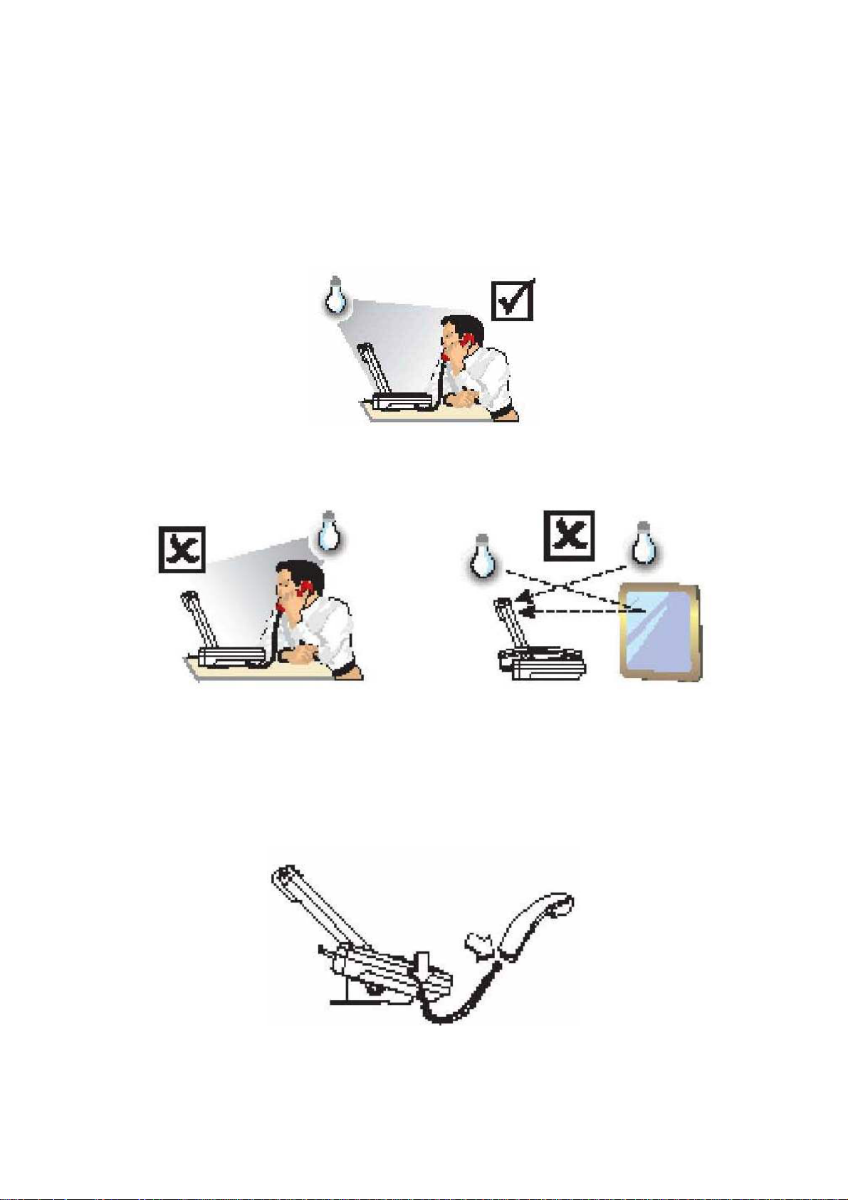
Step 1 Choose a proper location for installation.
The illuminant should be in the upper front of the user so that the light can shine on
the user’s face.
Avoid backlight – illuminant from user’s upper back is improper.
Avoid light reflection from mirror, which is behind the user.
Step 2 Hardware installation
Insert the handset cord into the socket upon the handset and the other end into the
socket on the left side of the machine.
13
Page 14
Step 3 Connecting to the Internet.
Plug one end of the LAN cable into the WAN port of the Video Phone machine, and
the other end into your switch/hub, cable modem, ADSL modem or the wall socket
which connects to switch/hub.
" Note:
1. The Video Phone can work as a hub by connecting the Video Phone to a computer
with a LAN cable. Please plug the LAN cable into the PC port on the back panel.
2. You can use the Video Phone as a PSTN telephone as well. By connecting the
phone line to the Video Phone, you may have it work as a PSTN telephone.
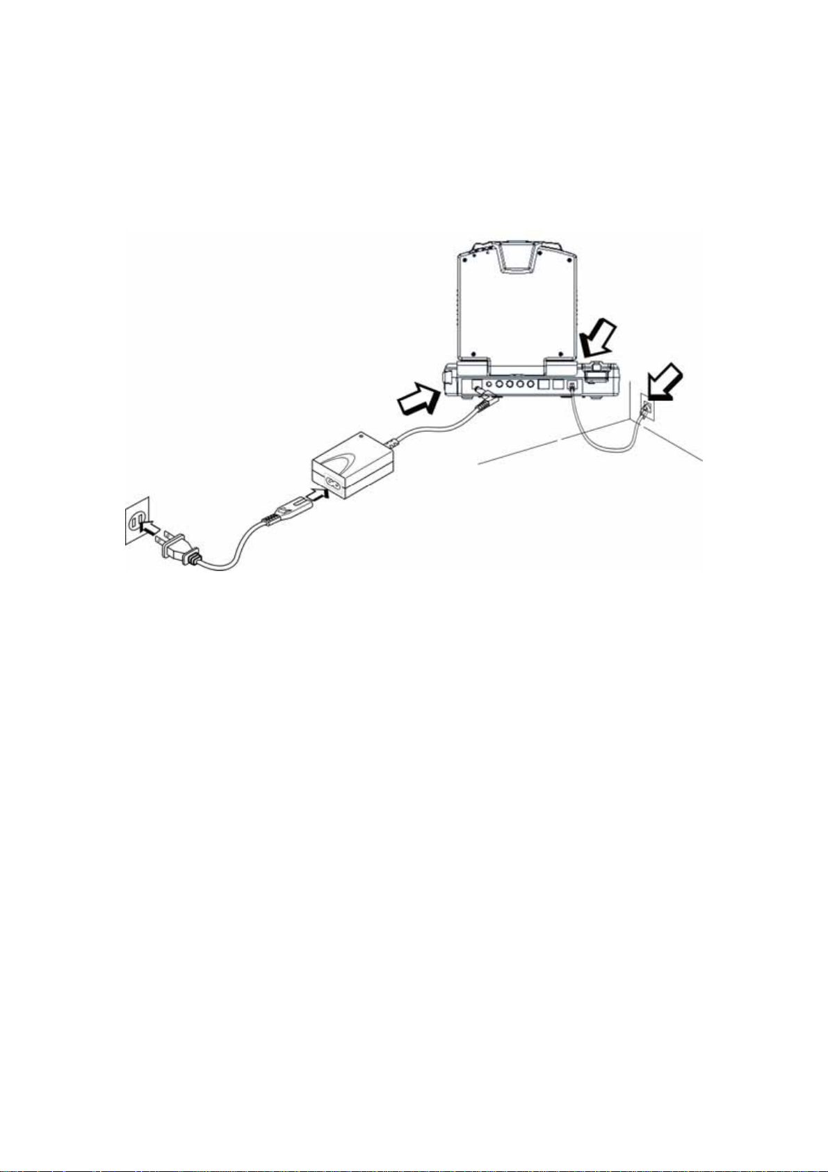
Step 4 Connecting the power cord.
Please refer to the picture above. Plug the power cord into a socket and use the
supplied cable to connect the machine.
14
Page 15
Step 5 Back panel introduction
15
Page 16
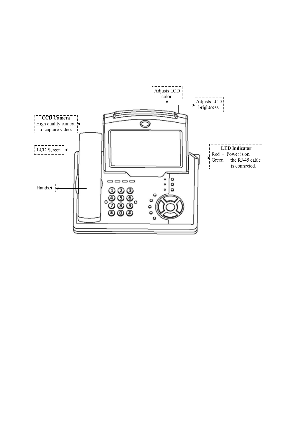
4. Getting to Know the Machine
Front View
16
Page 17

Keypad Panel
Keypad Panel
17
Page 18

Back View Side View
The LCD panel can be tilted
up or down to obtain the most
comfortable viewing position.
18
Page 19

5. System Configuration
After power on, the PWR/LNK LED on the top-right of LCD monitor turn red to
indicate it have received power. The LED will then turn green if the Ethernet network
connection is established. The conferencing phone should take about 30 seconds to
make power on self-test and system start up. In this period, the screen will show local
images. Please do not press any button on this period.
After the booting process is completed, the following page is shown on the LCD
monitor.
Press [Menu] button, a System Configuration page is shown. Please use [▲], [►],
[▼], and [◄] to move the highlight to the function you need to configure and [Enter]
to enter the function menu.
5.1 General
19
Page 20

a Auto-Answer Mode
The feature allows the Video Phone to answer incoming calls automatically.
1. General Æ select “Auto-Answer Mode.”
2. Press the [▲] or [▼] key to select the setting you want.
Enable – Machine automatically answers any incoming calls.
Disable – Incoming calls can be answered only when receiver picks up the
handset or presses the [Speaker] button.
3. Press the [ENTER] key to confirm the setting.
a Auto-Send Video
This function could make the Video Phone send image automatically when
conversing.
1. General Æ select “Auto-Send Video.”
2. Press the [▲] or [▼] key to select the setting you want.
Yes – Video Phone sends image automatically when conversing.
No – Video Phone does not send image automatically when conversing.
3. Press the [ENTER] key to confirm the setting.
a System Sleep
Sleep mode will be on when system is idle for a pre-set period.
1. General Æ select “System Sleep.”
2. Press the [ENTER] key and use number keys to input sleep time. (Up to 99
minutes.)
* To disable System Sleep function, please set the time to “0” minute. Use the
“®” key to delete a character.
3. Press the [▼] key to select “OK” and press [ENTER] to return to the previous
page.
When system is under sleep mode, press any key to wake up the system.
a Language Type
We provide Chinese and English for users to choose.
1. General Æ select “Language Type.”
2. Press the [▲] or [▼] key to select the setting you want.
3. Press the [ENTER] key to confirm the setting and return to the previous page.
" Note:
For special model, we provide Chinese and English. For normal model, we provide
English only.
20
Page 21

a Display Name
Display name represents your identification. The display name is shown when people
receive a call from you. You can also use the display names recorded in the phone
book sheet to contact people.
1. General Æ select “Display Name.”
2. Press [ENTER] and use the on-screen keyboard to input the display name.
3. Press the [▼] key to select “OK” and press [ENTER] to return to the previous
page.
a Security
This feature allows only the people who have the security password to enter the
system configuration settings. In this case, you don’t have to worry that the system
settings will be changed without notice.
1. General Æ select “Security.”
2. Press the [▲] or [▼] key to select the setting you want.
Enable – enable password protection. Users have to input the security
password next time when trying to enter system configuration
settings.
Disable – Disable password protection.
3. Press the [ENTER] key to save the setting. If you select “Enable”, please go on to
the next step.
a Password
1. General Æ select “Password.”
2. Press [ENTER] and use the on-screen keyboard to input your password.
(You can also use the keypad to key in numbers and letters. The capacity is 30
digits.)
3. Press the [▼] key to select “OK” and press [ENTER] to return to the previous
page.
21
Page 22

5.2 Network (ICF-1501)
a Bandwidth
Select appropriate bandwidth in compliance with your Internet transmission speed
when placing a call.
1. Network Æ select “Bandwidth.”
2. Press the [▲] or [▼] key to select the bandwidth you need.
768 – the maximum bandwidth is 768 Kbps.
512 – the maximum bandwidth is 512 Kbps.
384 – the maximum bandwidth is 384 Kbps.
256 – the maximum bandwidth is 256 Kbps.
128 – the maximum bandwidth is 128 Kbps.
3. Press the [ENTER] key to confirm the setting.
" Note:
Please set your bandwidth consumption in accordance with your Internet
bandwidth subscribed from your ISP.
a Network Mode
The Network Mode function is used for network configuration.
You can get the network setup information from your Internet Service Provider (ISP).
1. Network Æ select “Network Mode.”
2. Press the [▲] or [▼] key to select the network mode.
Manual – Fixed IP Mode. Acquire the subnet mask address, user IP address,
and router IP address from your ISP.
DHCP – Dynamic Host Configuration Protocol is used to auto-assign IP
addresses within a LAN.
PPPoE – PPPoE (Point-to-Point Protocol over Ethernet) protocol is used by
many Internet Service Providers. A PPPoE user name and PPPoE
22
Page 23

password should be provided.
3. Press the [ENTER] key to confirm the setting.
A. Manual
If your ISP provides you with one or more static IP addresses, you can setup your
network manually. However, you have to acquire subnet mask, user IP address, and
router IP address from your ISP.
1. Network Æ Bandwidth Æ Press [▲] or [▼].
Select a proper bandwidth in compliance with your Internet transmission speed.
2. Network Æ Network Mode Æ Press [▲] or [▼]. Select “Manual” mode.
3. Network Æ Subnet Mask Æ input your subnet mask.
4. Network Æ User IP Address Æ input your user IP address.
5. Network Æ Router IP Address Æ input your router IP address.
6. Press [ESC] to save your settings.
B. DHCP
1. Network Æ Network Mode Æ Press [▲] or [▼]. Select “DHCP” mode.
2. Press [ESC] to save your settings.
23
Page 24

C. PPPoE
If your ISP provides you with a dynamic IP address, you can set your network mode
to PPPoE. However, you have to acquire a PPPoE connection user name and
password from your ISP.
1. Network Æ Network Mode Æ Press [▲] or [▼]. Select “PPPoE” mode.
2. Network Æ PPPoE User Name Æ input your PPPoE user name.
3. Network Æ PPPoE Password Æ input your PPPoE password.
4. Press [ESC] to save your settings.
a DNS IP Address
1. Network Æ select “DNS IP Address.”
2. Press [ENTER] and use keyboard to input your DNS IP address.
3. Press [▼] to select “OK” and press [ENTER] to return to the previous page.
" Note:
Please register your DDNS on
http://www.dyndns.org
1. Please choose “Account” item.
2. After registering, the user will get DDNS user name and password.
3. After login, please enter add Host Services of my service. Then user can get
the hostname.
24
Page 25

a DDNS Hostname
Dynamic DNS hostname setup.
1. Network Æ select “DDNS Hostname.”
2. Press [ENTER] and use the number key to input your DDNS hostname.
* Press “®” to delete a word; press “*” to input a dot; press “ ” to switch
between upper case and lower case letters and numerals.
3. Press [▼] to select “OK” and press [ENTER] to return to the previous page.
a DDNS User Name
Dynamic DNS user name setup.
(The machine only supports the DDNS service provided from
http://www.syndns.orgDDNS)
1. Network Æ select “DDNS User Name.”
2. Press [ENTER] and use the number key to input your DDNS user name.
* Press “®” to delete a word; press “*” to input a dot; press “
” to switch
between upper case and lower case letters and numerals.
3. Press [▼] to select “OK” and press [ENTER] to return to the previous page.
a DDNS Password
Dynamic DNS password setup.
1. Network Æ select “DDNS Password.”
2. Press [ENTER] and use the number key to input your DDNS password. (You can
also use the keypad to key in numbers and letters. The capacity is 30 digits.)
* Press “®” to delete a word; press “*” to input a dot; press “ ” to switch
between upper case and lower case letters and numerals.
3. Press [▼] to select “OK” and press [ENTER] to return to the previous page.
After all settings, please press [ESC] to save your settings.
25
Page 26

5.3 Network (ICF-1550)
a Bandwidth
Select appropriate bandwidth in compliance with your Internet transmission speed
when placing a call.
1. Network Æ select “Bandwidth.”
2. Press the [▲] or [▼] key to select the bandwidth you need.
No Limit – there is no bandwidth limit.
768 – the maximum bandwidth is 768 Kbps.
512 – the maximum bandwidth is 512 Kbps.
384 – the maximum bandwidth is 384 Kbps.
256 – the maximum bandwidth is 256 Kbps.
128 – the maximum bandwidth is 128 Kbps.
3. Press the [ENTER] key to confirm the setting.
" Note:
Please set your bandwidth consumption in accordance with your Internet
bandwidth subscribed from your ISP.
a Network Mode
The Network Mode function is used for network configuration.
You can get the network setup information from your Internet Service Provider (ISP).
1. Network Æ select “Network Mode.”
2. Press the [▲] or [▼] key to select the network mode.
Manual – Fixed IP Mode. Acquire the subnet mask address, user IP address,
and router IP address from your ISP.
DHCP – Dynamic Host Configuration Protocol is used to auto-assign IP
addresses within a LAN.
PPPoE – PPPoE (Point-to-Point Protocol over Ethernet) protocol is used by
26
Page 27

many Internet Service Providers. A PPPoE user name and PPPoE
password should be provided.
3. Press the [ENTER] key to confirm the setting.
D. Manual
If your ISP provides you with one or more static IP addresses, you can setup your
network manually. However, you have to acquire subnet mask, user IP address, and
router IP address from your ISP.
1. Network Æ Bandwidth Æ Press [▲] or [▼].
Select a proper bandwidth in compliance with your Internet transmission speed.
2. Network Æ Network Mode Æ Press [▲] or [▼]. Select “Manual” mode.
3. Network Æ Subnet Mask Æ input your subnet mask.
4. Network Æ User IP Address Æ input your user IP address.
5. Network Æ Router IP Address Æ input your router IP address.
6. Press [ESC] to save your settings.
E. DHCP
1. Network Æ Network Mode Æ Press [▲] or [▼]. Select “DHCP” mode.
2. Press [ESC] to save your settings.
27
Page 28

F. PPPoE
If your ISP provides you with a dynamic IP address, you can set your network mode
to PPPoE. However, you have to acquire a PPPoE connection user name and
password from your ISP.
1. Network Æ Network Mode Æ Press [▲] or [▼]. Select “PPPoE” mode.
2. Network Æ PPPoE User Name Æ input your PPPoE user name.
3. Network Æ PPPoE Password Æ input your PPPoE password.
4. Press [ESC] to save your settings.
After all settings, please press [ESC] to save your settings.
5.4 Advanced (ICF-1501)
a Gatekeeper Mode
When register a gatekeeper, you can assign a number to the Video Phone. This makes
the Video Phone user-friendly, as users only have to dial a number instead of entering
an IP address when making a call.
1. Advanced Æ select “Gatekeeper Mode.”
2. Press [▲] or [▼] to select the setting you want.
Disable – Not to register a gatekeeper.
Auto – Auto search for a gatekeeper IP address.
28
Page 29

Manual – User must input a gatekeeper IP address.
3. Press [▼] to select “OK” and press [ENTER] to return to the previous page.
4. If the gatekeeper mode is set to “Manual”, please continue setting up “GK IP
Address”, “GK Phone Number”, “GK Alias Name”, and “H.235 Password.”
a GK IP Address
Enter the gatekeeper IP address assigned to the machine. (Please acquire subnet mask
address from your ISP.)
1. Advanced Æ select “GK IP Address.”
2. Press [ENTER] and use number keys to input your gatekeeper IP address.
Press “®” to delete a word; press [◄] to delete all.
3. Press [▼] to select “OK” and press [ENTER] to return to the previous page.
a GK Phone Number
You can register a phone number at the gatekeeper to make the dialing of Video
Phone more user-friendly.
(Please set your gatekeeper mode to “Manual” or “Auto.” Contact your gatekeeper
service provider for gatekeeper registration.)
1. Advanced Æ select “GK Phone Number.”
2. Press [ENTER] and use number keys to input your GK phone number.
(The capacity is 30 digits.)
* Press “®” to delete a word. Press “*” to input a dot.
3. Press [▼] to select “OK” and press [ENTER] to return to the previous page.
a GK Alias Name
You can register a name or number at the gatekeeper to make the dial of Video Phone
more user-friendly.
(Please set your gatekeeper mode to “Manual” or “Auto.” Contact your gatekeeper
service provider for gatekeeper registration.)
The alias name is the GK name given to the Machine by GK Manager. It may be used
in place of an IP address when dialing H.323 calls.
1. Advanced Æ select “GK Alias Name.”
2. Press [ENTER
] to enter the on-screen keyboard to input your GK alias name.
(You can also use the keypad to key in numbers and letters. The capacity is 30
digits.)
* Press “®” to delete a word; press “*” to input a dot; press “
” to switch
between upper case and lower case letters and numerals.
3. Press [▼] to select “OK” and press [ENTER] to return to the previous page.
29
Page 30

a H235 Password
Please enter your H.235 password here.
1. Advanced Æ select “H235 Password.”
2. Press [ENTER] to enter the on-screen keyboard to input your H.235 password.
* Press “®” to delete a word; press “*” to input a dot; press “ ” to switch
between upper case and lower case letters and numerals.
3. Press [▼] to select “OK” and press [ENTER] to return to the previous page.
a Detect NAT RIP
NAT RIP is the abbreviation of “Network Address Translation” and “Routing
Information Protocol.” By enabling this function, the Video Phone can detect if the
other is under NAT mode.
1. Advanced Æ select “Detect NAT RIP.”
2. Press [▲] or [▼] to select Enable or Disable.
3. Press [ENTER] to save the setting.
a NAT Route
If you’re a virtual IP user, please enable this function and continue setting the NAT
route IP.
1. Advanced Æ select “NAT Route.”
2. Press [▲] or [▼] to select Enable or Disable.
3. Press [ENTER] to save the setting.
a NAT Route IP
1. Advanced Æ select “NAT Route IP.”
2. Press [ENTER] to enter the on-screen keyboard to input the NAT router IP
address.
30
Page 31

3. Press [▼] to select “OK” and press [ENTER] to save the setting.
a UDP Base Port
UDP Base port is for transmit audio and video data. The port number is set to 5000 by
default. (If you set it over the maximum number 65536, system will adjust it to 65000
automatically.) If you’re not using NAT, you may skip this item.
1. Advanced Æ select “UDP Base Port.”
2. Press [ENTER] and input the UDP Base port number.
3. Press [▼] to select “OK” and press [ENTER] to save the setting.
a Default
You can use this function to initialize System Configuration to default value.
1. Advanced Æ select “Default.”
2. Press [▲] or [▼] to select the setting you want.
No Action – Retain the present setting
Configuration – Initiate system configurations to default value
Phone Book – Initiate phone book to default value
Call History – Initiate call history record to default value
3. Press [ENTER] to return to the previous page.
a Picture Quality
This function is responsible for the video quality sent to the remote site. There are
four kinds of format (Auto, CIF, QCIF, SQCIF) provided.
1. Advanced Æ select “Picture Quality.”
2. Press [▲] or [▼] to select the setting you want.
Auto – The system automatically switches for the best picture quality.
CIF – It is ISO standard of Sharp. (352 × 288 pixels)
QCIF – It is ISO standard of Good. (176 × 144 pixels)
SQCIF – It is ISO standard of Smooth. (128 × 96 pixels)
31
Page 32

3. Press [ENTER] to confirm the setting.
* While bandwidth is low, low-resolution image format (QCIF or SQCIF) is
suggested for getting real-time image.
a Audio Format
The audio format can be adjusted to compensate for audio distortion caused by high
packet loss. Select a proper audio protocol for audio transmission.
1. Advanced Æ select “Audio Format.”
2. Press [▲] or [▼] to select the setting according to your need.
Auto – The system automatically switches. (Default)
G. 711 – 64Kbps
G. 723 – 6.3Kbps
G.729 – 8Kbps
3. Press [ENTER] to confirm and save the setting.
a Remote Update
Remote Update provides users to upgrade system software. (Remote Update function
enables users to upgrade Video Phone software online.)
1. Advanced Æ select “Remote Update.”
2. Press [ENTER] and select Yes if you want to do remote update.
3. Press [ENTER] to confirm the setting and go on to the next step.
a Update IP Address
1. Advanced Æ select “Update IP Address.”
2. Press [ENTER] and input the update IP address.
3. Use the [▼] key to select “OK.”
4. Press [ESC] to save the setting and start updating the software.
32
Page 33

a Upgrading the System Software
Please set the network mode to “Manual”, “DHCP”, or “PPPoE” first.
◎ Manual
1. Use the number keys to input your subnet Mask IP address.
(You can also use the keypad to input characters directly.)
2. Use the number keys to input your User IP address.
3. Use the number keys to input your Router IP address.
4. Use the number keys to input your Update IP address.
5. Press [ESC] to save the setting and start upgrading the software.
(It will take about fifteen seconds to start upgrading. Please wait patiently.)
◎ DHCP
1. Use the [▼] key to go to Update IP Address and input your Update IP address.
2. Press [ESC] to save the setting and start upgrading the software.
(It will take about fifteen seconds to start upgrading. Please wait patiently.)
33
Page 34

◎ PPPoE
(PPPoE user name and PPPoE password under “Network” menu must be set.)
1. Use the [▼] key to go to Update IP Address and input your Update IP address.
2.
Press [ESC] to save the setting and start upgrading the software.
(It will take about fifteen seconds to start upgrading. Please wait patiently.)
After network setting, press the [Speaker] key to save the settings and start updating.
After updating, system will restart automatically. (Please wait for about fifteen
seconds.)
If there is no upgrade file to update, the screen will return to Remote Update page.
Press [Menu] and then press [ENTER]. The system will rest
return to standby mode. (Please wait for about ten seconds.)
art automatically and
" Note:
The system only accepts the redaction software higher than original.
34
Page 35

a Exit System Configuration
Please press the [ESC] button to exit the system configuration.
5.5 Advanced (ICF-1550)
a Server Mode
You can choose to use a SIP server or not here in this item.
When the ICF-1550 is registered on a SIP server, it is provided related setup
information. SIP can offer callers a choice of ways of reaching a person. Using SIP
makes the ICF-1550 user-friendly, as users only have to dial the “SIP user name”
instead of entering a user IP address when making a call.
1. Advanced Æ select “Server Mode.”
2. Press [▲] or [▼] to select the setting you want.
Disable – Not to register a SIP server.
Proxy – To register a SIP server and use it for communication.
3. Press [ENTER] to confirm the setting and return to the previous page.
*** If you set this item to “Proxy”, please continue setting the “SIP Proxy IP Addr”,
“SIP User Name”, “Password”, “Domain/Realm” and “Port” items. Detailed setup
instructions are as follows.
a SIP Proxy IP Addr (SIP Proxy IP Address)
Enter the SIP Proxy IP address assigned to the machine.
1. Advanced Æ select “SIP Proxy IP Addr.”
2. Press [ENTER] and use the on-screen keyboard to input your SIP proxy IP
address.
Press “®” to delete a word; press “*” to input a dot; press “
” to switch between
upper case and lower case letters and numerals.
3. Press [▼] to select “OK” and press [ENTER] to return to the previous page.
35
Page 36

a SIP User Name
The SIP server will assign a phone number for the ICF-1550 to make the dialing of
ICF-1550 more user-friendly.
(Please set your server mode to “Proxy.” Then ICF-1550 can contact each other by
dialing the other’s SIP user name.)
1. Advanced Æ select “SIP User Name.”
2. Press [ENTER] and use the on-screen keyboard to input your SIP user name.
(The capacity is 30 digits.)
* Press “®” to delete a word; press “*” to input a dot; press “
” to switch
between upper case and lower case letters and numerals.
3. Press [▼] to select “OK” and press [ENTER] to return to the previous page.
a Password
Please enter the password assigned by the SIP server.
1. Advanced Æ select “Password.”
2. Press [ENTER] to enter the on-screen keyboard to input your password.
(You can also use the keypad to key in numbers and letters. The capacity is 30
digits.)
* Press “®” to delete a word; press “*” to input a dot; press “
” to switch
between upper case and lower case letters and numerals.
3. Press [▼] to select “OK” and press [ENTER] to return to the previous page.
a Domain/Realm
Please enter your domain/realm provided by the SIP server here.
1. Advanced Æ select “Domain/Realm.”
2. Press [ENTER] to enter the on-screen keyboard to input your domain/realm.
* Press “®” to delete a word; press “*” to input a dot; press “ ” to switch
between upper case and lower case letters and numerals.
3. Press [▼] to select “OK” and press [ENTER] to return to the previous page.
36
Page 37

a Port
Port is used for register a SIP server. Most of the time, the port number is 5060. If the
SIP server specially assigns a port number to you, please use the number assigned.
1. Advanced Æ select “Port.”
2. Press [ENTER] and use the number keys to input the port number you use.
3. Press [▼] to select “OK” and press [ENTER] to return to the previous page.
a Default
You can use this function to initialize System Configuration to default value.
1. Advanced Æ select “Default.”
2. Press [▲] or [▼] to select the setting you want.
No Action – Retain the present setting
Configuration – Initiate system configurations to default value
Phone Book – Initiate phone book to default value
Call History – Initiate call history record to default value
3. Press [ENTER] to return to the previous page.
a Picture Quality
This function is responsible for the video quality sent to the remote site. There are
three kinds of format (Auto, CIF, QCIF) provided.
1. Advanced Æ select “Picture Quality.”
2. Press [▲] or [▼] to select the setting you want.
Auto – The system automatically switches for the best picture quality.
CIF – It is ISO standard of Sharp. (352 × 288 pixels)
QCIF – It is ISO standard of Good. (176 × 144 pixels)
SQCIF – It is ISO standard of Smooth. (128 × 96 pixels)
3. Press [ENTER] to confirm the setting.
* While bandwidth is low, low-resolution image format (QCIF or SQCIF) is
suggested for getting real-time image.
37
Page 38

a Audio Format
The audio format can be adjusted to compensate for audio distortion caused by high
packet loss. Select a proper audio protocol for audio transmission.
1. Advanced Æ select “Audio Format.”
2. Press [▲] or [▼] to select the setting according to your need.
Auto – The system automatically switches. (Default)
G.711 – 64Kbps
G.723 – 6.3Kbps
G.729 – 8Kbps
3. Press [ENTER] to confirm and save the setting.
a Remote Update
Remote Update provides users to upgrade system software. (Remote Update function
enables users to upgrade Video Phone software online.)
1. Advanced Æ select “Remote Update.”
2. Press [ENTER] and select Yes if you want to do remote update.
3. Press [ENTER] to confirm the setting and go on to the next step.
a Update IP Address
1. Advanced Æ select “Update IP Address.”
2. Press [ENTER] and input the update IP address.
3. Use the [▼] key to select “OK.”
4. Press [ESC] to save the setting and start updating the software.
a Upgrading the System Software
Please set the network mode to “Manual”, “DHCP”, or “PPPoE” first.
38
Page 39

◎ Manual
1. Use the number keys to input your subnet Mask IP address.
(You can also use the keypad to input characters directly.)
2. Use the number keys to input your User IP address.
3. Use the number keys to input your Router IP address.
4. Use the number keys to input your Update IP address.
5. Press [ESC] to save the setting and start upgrading the software.
(It will take about fifteen seconds to start upgrading. Please wait patiently.)
◎ DHCP
1. Use the [▼] key to go to Update IP Address and input your Update IP address.
2. Press [ESC] to save the setting and start upgrading the software.
(It will take about fifteen seconds to start upgrading. Please wait patiently.)
39
Page 40

◎ PPPoE
(PPPoE user name and PPPoE password under “Network” menu must be set.)
1. Use the [▼] key to go to Update IP Address and input your Update IP address.
2. Press [ESC] to save the setting and start upgrading the software.
(It will take about fifteen seconds to start upgrading. Please wait patiently.)
After network setting, press the [Speaker] key to save the settings and start updating.
After updating, system will restart automatically. (Please wait for about fifteen
seconds.)
If there is no upgrade file to update, the screen will return to Remote Update page.
Press [Menu] and then press [ENTER]. The system will restart automatically and
return to standby mode. (Please wait for about ten seconds.)
" Note:
The system only accepts the redaction software higher than original.
40
Page 41

a Exit System Configuration
Please press the [ESC] button to exit the system configuration.
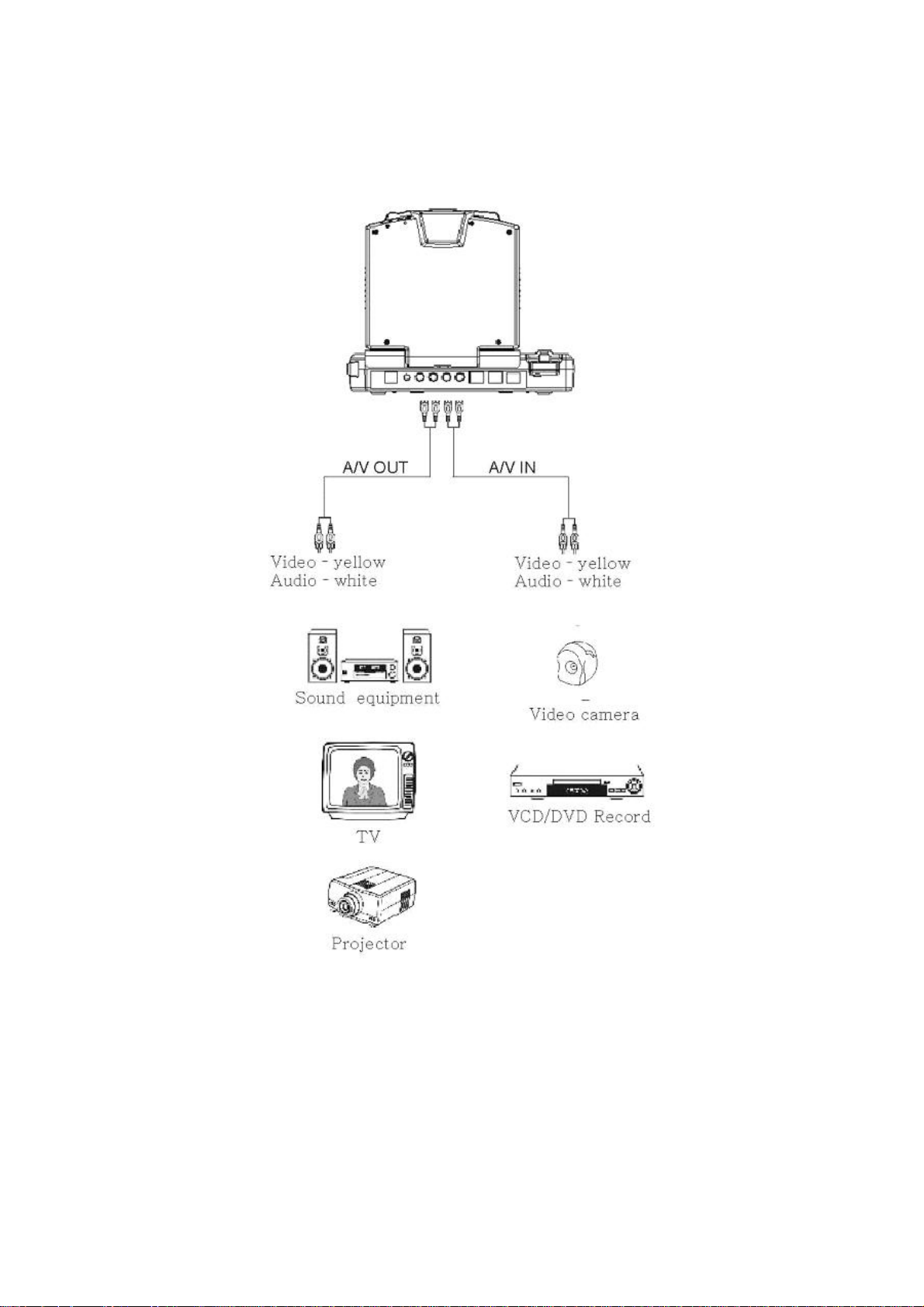
5.6 Selecting A/V Source
Video Phone supports one external A/V input channel and one A/V output channel.
(A/V In – EXT; A/V Out – Main)
a Selecting Video Source
1. Press the [Channel] button.
2. Use [▲] or [▼] to enter Video Channel Selection.
3. User [◄] or [►] to switch channels.
a Selecting Audio Source
1. Press the [Channel] button.
2. Use [▲] or [▼] to enter Audio Channel Selection.
3. User [◄] or [►] to switch channels.
41
Page 42

6 Phone Book Setup
The Video Phone provides an address book to store up to 100 access names and their
IP addresses. You can make a speed dial directly from the phone book. (The capacity
for each entry is 30 digits.)
1. In standby mode, press [Phone Book] to enter the phone book sheet.
2. Use [▲] or [▼] to select an entry for storing name and IP address.
3. Press the [ENTER] key to input the name or IP address.
4. Press [▼] to select “OK.” Press [ENTER] to confirm the setting.
5. Press [ESC] to leave phone book sheet and return to standby mode.
※ Quick search address:
If you want to search the thirty-second phone address, you may setup the following
steps.
1. You can press [Phone Book] and press “3” in the remote control.
2. Then the sign will move to the thirtieth address.
3. User can use the [▼] key to move to the 32 one.
6.1 Input Characters
Select one entry from the phone book and press the [ENTER] button to enter the
alphabet, number, and symbol chart.
1. Use the cursor to select the letter, digit, or symbol.
2. Use [ENTER] to confirm and input the letter, digit, or symbol you chose. (You
can also use keypad to input characters directly.)
* Press “®” to delete a word; press “*” to input a dot; press “
between upper case and lower case letters and numerals.
” to switch
42
Page 43

3. Press [▼] to select “OK”, and press [ENTER] to return to the previous page.
6.2 Input IP Address
Select one entry from the phone book and press the [ENTER] button to enter IP
addresses.
1. Please use the number keys to input the user IP address.
* Press “®” to delete a word; press “*” to input a dot; press [◄] delete all.
2. Press the [▼] key to select “OK” and press [ENTER] to return to the previous
page.
3. Press [ESC] to leave phone book sheet and return to standby mode.
6.3 Ten Records Communicating by Phones
After communicating, press [Call History] to review the call history. The most recent
ten incoming and outgoing IP records are kept in Call History.
1. Press the [Call History] key to enter the call history sheet.
※ Press [◄] or [►] to select record of incoming or outgoing calls.
※ Press [▲] or [▼] to select one of the recent ten records.
2. Press the [Speaker] key to connect.
3. After communicating, system will return to standby mode automatically.
43
Page 44

7. General Operation
Before making a video call, please make sure that the unit has been installed and set
up successfully.
When trying to make a video call, the user sees the following picture.
When connecting, the user sees the picture below.
7.1 Making Video Calls
◎ Under General State
1. In standby mode, pick up the handset or press the [Speaker] button. Then dial the
IP address of the remote site.
2. Press the [ENTER] button to confirm and commence the Internet connecting.
3. When the connection is set up successfully, the video communication will start
and the remote site video will be shown on the screen of local site.
4. Please hang up the handset or press the [Speaker] again to end the Video Phone
call.
44
Page 45

◎ By Using the Phone Book
The phone book provides users a convenient way for retrieving the IP addresses of
some regular called parties.
1. Press the [Phone Book] button to enter the phone book sheet.
2. Press the [▲] or [▼] key to select the name, or use [◄] or [►] to select the IP
address you want to call.
3. Press the [Speaker] button to make connection.
4. When the connection starts successfully, the remote site video will be shown on
the screen of local site.
5. When finish, press the [Speaker] button to end the connection.
" Note:
You can locate a certain entry promptly by entering the entry number.
1. In standby mode, press the [Phone Book] button to enter the phone book
sheet.
2. Press “3” and “2”. The Video Phone will connect with the thirty-second IP
address automatically after a moment.
3. When the connection is up successfully, the video communication will start
and the remote site video will be shown on the screen of local site.
4. When finish, press the [Speaker] button to end the connection.
7.2 Making Phone Calls under PSTN
1. Press the [PSTN] button on the panel.
2. Pick up the handset or press the [Speaker] key on the panel.
3. Input the number you want to call and press [ENTER] to make connection.
4. When finish, hang up the handset or press the [Speaker] button to end the
connection.
7.3 Receiving Video Calls
If the auto-answer mode is enabled, the Video Phone answers calls automatically.
If the auto-answer mode is disabled, users have to pick up the handset or press the
[Speaker] button to answer phone calls.
45
Page 46

8. On-line Operation
All the on-line operations can ONLY be done during communication.
8.1 Snapshot
The snapshot function captures the image from remote site. This function allows the
two parties to see more details of the pictures.
1. Press the [Snapshot] button once to take a snapshot of the remote site image.
2. Press the [Snapshot] button again to release the image and return to current video
call.
(The “Snapshot” will disappear once the captured image is released.)
8.2 Switching the Video and Audio Source
The Video Phone allows you to connect with one external video/audio source, such as
a camera. When the external device is connected to the Video Phone, you can switch
to the video and/or audio taken by the external device.
46
Page 47

a
Video Channel Select
1. Press the [Channel] button.
2. Use [▲] or [▼] to switch to Video Channel Selection.
3. Use [◄] or [►] to switch to the external video source.
Main (Built-in) Æ EXT (from A/V In)
4. Press [Channel] or [ESC] button to save the setting and exit.
a Audio Channel Select
1. Press the [Channel] button.
2. Use [▲] or [▼] to switch to Audio Channel Selection.
3. Use [◄] or [►] to switch to the external audio source.
Main (Built-in) → EXT (from A/V In)
4. Press [Channel] or [ESC] button to save the setting and exit.
8.3 Activating Video/Audio Mute
a Activate Video Mute
If you want to temporarily stop video or audio transmission to the remote site during
connection, you can use this function to conceal the local video or audio.
1. Press the [Privacy] button to enter Privacy function.
2. Use [◄] or [►] to control video On/Off.
47
Page 48

On: transmits video normally Off: video cannot be transmitted
3. Press the [Privacy] button again to confirm the privacy setting mode.
a Activate Audio Mute
1. Press the [Privacy] button to enter Privacy function.
2. Use [▲] or [▼] to select the Audio Channel.
3. Use [◄] or [►] to control audio On/Off.
On: transmits audio normally Off: audio cannot be transmitted
4. Press the [Privacy] button again to confirm the privacy setting mode.
" If you disable the “Auto-Answer Mode” in the system configuration, the A/V
transmission setting function will be disabled.
a Switching Images between Remote and Local Site
You can switch images between remote and local end by pressing the [Window]
button. There are three types of image arrangement: remote + local, remote only, and
local only.
8.4 Operation State
This function is to display the status of Network connecting, for example, connecting
time, TX/RX Bit Rate as well as TX/RX Frame Rate and so on. For getting better
quality, you can adjust the settings below under online mode.
TX: Transmitting Rate RX: Receiving Rate
Encode: Encoding Rate Decode: Decoding Rate
48
Page 49

9. Troubleshooting
1. Boot up failure
a) Please check if the power cord is correctly connected.
b) Please make sure the power adapter is well connected to your Video Phone
and the plug is well plugged into the socket. When the power supply is
normal, the LED indicator is RED and it turns GREEN when you connect a
network wire to your Video Phone.
c) Please check if the power adapter is out of order. The LED indicator on the
power adapter should be GREEN when power is on.
2. Connection failure
a) Please check if the LAN cable is well connected to the RJ-45 LAN port of
your Video Phone and make sure the RJ-45 joint on your network wire
functions normally.
b) Please check if your system configuration is correct.
c) Please confirm if the IP address of the remote site is correct.
3. The Video Phone keeps ringing but doesn’t establish the connection.
This is because you disable the auto-answer mode. In this case, you have to pick
up the handset or press the [Speaker] button to answer the phone.
4. The picture is block or scrappy.
This is caused by bad Internet connection quality or insufficient bandwidth. We
recommend that you set the picture quality to SQCIF (path: Menu Æ Advanced
Æ Picture Quality) and set the bandwidth to 128Kbps.
5. Local image is blurry.
Please adjust the camera focus by using the camera focus tuning knob around
the camera.
49
Page 50

6. Fail to response to inbound calls from LAN phone or VoIP gateway.
a) Please check with the caller if the VoIP equipment is H.323 / SIP 2.0
compliant.
b) Please enter “General” in Menu to check if the Auto-Send Video is disabled.
If not, please disable it.
7. The remote site receives images but no sound from the local site.
Please confirm if the audio mute function is on.
8. Voice is unclear or discontinuous.
Please set the speaker volume to normal degree. If the speaker volume is too low
or too high, the echo cancellation mechanism could be overloading and thus
damage sound quality.
9. How to use the Video Phone if you don’t have a static IP address?
a) If you have MIS staff, please turn to them for assistance.
b) Please make sure if the router you use supports DMZ. Please contact the
router manufacturer for setting problems.
c) Please reboot the router after finishing DMZ setting.
d) Please ping your IP address. If you fail to locate the IP address, there must
be some errors in the router setting. Please go through the router setting and
correct the errors.
e) Machine configuration:
Network H.323 (ICF-1501)
Network Mode: manual
Detect NAT RIP: enable
User IP Address: DMZ IP
Router IP Address: Your static IP
address for Gateway (If you don’t know,
please use the commend “ipconfig” in
your computer to check it.)
Network SIP 2.0 (ICF-1550)
Network Mode: manual
User IP Address: DMZ IP
Router IP Address: Your static IP address for Gateway (If you don’t know,
50
Page 51

please use the commend “ipconfig” in your computer to check it.)
10. How to connect the machine with GATEWAY? (ICF-1501)
a) H.323: Audio Format: G.711
Software keyboard: enable
b) Dial number: (EX: 1004@211.72.147.254)
11. How to check the firmware version of the Video Phone?
Please press the [Status] button.
12. How to set dynamic IP under PPPoE mode?
Network setup as follows:
Network Mode: PPPoE
DDNS User Name:
DDNS Password: (Please contact your ISP for password.)
13. Why the communication quality is poor?
This is caused by poor Internet connection quality or insufficient bandwidth.
Please test your Video Phone bandwidth from 128Kbps and up till you get better
quality communication. Meanwhile, you can also try to lower your Video Phone
picture quality to lower the bandwidth consumption.
14. How to upgrade your machine?
Please refer to Video Phone upgrade instruction.
51
 Loading...