

Page 1

802.11g Wireless Broadband Router
WRT-416
User’s Manual
Page 2

Copyright
Copyright © 2009 by PLANET Technology Corp. All rights reserved. No part of this publication may be
reproduced, transmitted, transcribed, stored in a retrieval system, or translated into any language or
computer language, in any form or by any means, electronic, mechanical, magnetic, optical, chemical,
manual or otherwise, without the prior written permission of PLANET.
PLANET makes no representations or warranties, either expressed or implied, with respect to the contents
hereof and specifically disclaims any warranties, merchantability or fitness for an y particular purpose. Any
software described in this manual is sold or licensed "as is". Should the programs prove defective following
their purchase, the buyer (and not PLANET, its distributor, or its dealer) assumes the entire cost of all
necessary servicing, repair, and any incidental or consequential damages resulting from any defect in the
software. Further, PLANET reserves the right to revise this publication and to make changes from time to
time in the contents hereof without obligation to notify any person of such revision or changes.
All brand and product names mentioned in this manual are trademarks and/or registered trademarks of
their respective holders.
Federal Communication Commission Interference Statement
This equipment has been tested and found to comply with the limits for a Class B digital device, pursuant to
Part 15 of FCC Rules. These limits are designed to provide reasonable protection against harmful
interference in a residential installation. This equipment generates, uses, and can radiate radio frequenc y
energy and, if not installed and used in accordance with the instructions, may cause harmful interference to
radio communications. However, there is no guarantee that interference will not occur in a particular
installation. If this equipment does cause harmful interference to radio or television reception, which can be
determined by turning the equipment off and on, the user is encouraged to try to correct the interference by
one or more of the following measures:
1. Reorient or relocate the receiving anten na.
2. Increase the separation between the equipment and receiver.
3. Connect the equipment into an outlet o n a ci rcuit different from that to which the receiver is connected.
4. Consult the dealer or an expe rienced radio technician for help.
FCC Caution
To assure continued compliance. (example-use only shielded interface cables when connecting to
computer or peripheral devices). Any changes or modifications not expressly approved by the party
responsible for compliance could void the user’s authority to operate the equipment.
This device complies with Part 15 of the FCC Rules. Operation is subject to the Following t wo conditions:
( 1 ) This device may not cause harmful interference, and ( 2 ) this Device must accept any interference
received, including interference that may cause undesired operation.
Federal Communication Commission (FCC) Radiation Exposure Statement
This equipment complies with FCC radiation exposure set forth for an uncontrolled environment. In order to
avoid the possibility of exceeding the FCC radio frequency exposure limits, human proximity to the antenna
shall not be less than 20 cm (8 inches) during normal operation.
R&TTE Compliance Statement
This equipment complies with all the requirements of DIRECTIVE 1999/5/CE OF THE EUROPEAN
PARLIAMENT AND THE COUNCIL OF 9 March 1999 on radio equipment and telecommunication terminal
Equipment and the mutual recognition of their conformity (R&TTE)
The R&TTE Directive repeals and replaces in the directive 98/13/EEC (Telecommunications Terminal
Equipment and Satellite Earth Station Equipment) As of April 8,2000.
Page 3

Safety
This equipment is designed with the utmost care for the safet y of those who install and use it. However,
special attention must be paid to the dangers of electric shock and static electricity when working with
electrical equipment. All guidelines of this and of the computer manufacture must therefore be allowed at all
times to ensure the safe use of the equipment.
EU Countries Not Intended for Use
The ETSI version of this device is intended for home and office use in Austria Belgium, Denmark, Finland,
France (with Frequency channel restrictions). Germany, Greece, Ireland, Italy, Luxembourg .The
Netherlands, Portugal, Spain, Sweden and United Kingdom.
The ETSI version of this device is also authorized for use in EFTA member states Iceland, Liechtenstein,
Norway and Switzerland.
Potential Restrictive Use
France: Only channels 10,11,12 and 13
WEEE Regulation
To avoid the potential effects on the environment and human health as a result of the presence of
hazardous substances in electrical and electronic equipment, end users of electrical and
electronic equipment should understand the meaning of the crossed-out wheele d bin symbol. Do
not dispose of WEEE as unsorted municipal waste and have to collect such WEEE separately.
Revision
User’s Manual for PLANET Wireless Broadband Router
Model: WRT-416
Rev: 1.0 (July, 2009)
Part No. EM-WRT416v2
Page 4

Table of Contents
Chapter 1 Introduction............................................................................ 5
1.1 Package Content........................................................................................................................ 5
1.2 Features.....................................................................................................................................5
1.3 Specification..............................................................................................................................5
1.4 Wireless Performance............................................................................................................... 6
Chapter 2 Hardware Installation ................................................................ 7
2.1 System Requirement.................................................................................................................7
2.2 Hardware Connection................................................................................................................7
2.3 LED Indicators.......................................................................................................................... 8
2.4 Back View.................................................................................................................................9
Chapter 3 Configuring Local Networking................................................... 10
Chapter 4 Web Configuration ................................................................. 12
4.1 Web Login...............................................................................................................................12
4.2 Convenient Setup....................................................................................................................13
4.2.1 Operation Mode........................................................................................................14
4.2.2 Time Zone..................................................................................................................14
4.2.3 LAN.............................................................................................................................15
4.2.4 WAN...........................................................................................................................16
4.2.5 Wireless Basic Setting............................................................................................. 16
4.2.6 Wireless Encryption ................................................................................................. 17
4.3 LAN Setup ..............................................................................................................................18
4.4 Internet Setup..........................................................................................................................19
Chapter 5 Web Configuration ................................................................. 21
5.1 Web Login...............................................................................................................................21
5.2 Advanced Setting....................................................................................................................22
5.3 Security ................................................................................................................................... 23
5.3.1 None...........................................................................................................................24
5.3.2 WEP only...................................................................................................................24
5.3.3 802.1x&WEP............................................................................................................. 25
5.3.4 WPA............................................................................................................................26
5.4 Access control......................................................................................................................... 27
5.5 WDS Setting ...........................................................................................................................27
5.6 Site survey............................................................................................................................... 28
Chapter 6 System Information ................................................................ 29
6.1 Status....................................................................................................................................... 29
6.2 Statistic.................................................................................................................................... 29
6.3 System Log .............................................................................................................................30
Chapter 7 Application & Gaming ............................................................. 31
7.1 Virtual Service ........................................................................................................................31
7.2 DMZ........................................................................................................................................ 32
Chapter 8 Security management ............................................................. 33
8.1 Port Filtering........................................................................................................................... 33
8.2 IP Filtering ..............................................................................................................................33
8.3 MAC Filtering......................................................................................................................... 34
8.4 URL Filtering.......................................................................................................................... 35
8.5 URL Filtering.......................................................................................................................... 35
8.6 DDNS...................................................................................................................................... 37
Chapter 9 System Management............................................................... 38
9.1 Time Zone Setting................................................................................................................... 38
9.2 Upgrade Firmware ..................................................................................................................38
Page 5

Chapter 1 Introduction
Thank you for purchasing WRT-416. This device features the latest innovation wireless technology making
the wireless networking world happened. This manual guides you on how to install and properly use the
WRT-416 in order to take full advantage of its features.
1.1 Package Content
WRT-416 x 1
Ethernet cable x 1
Power Adapter x 1
User’s Manual CD x 1
Quick Installation Guide x 1
Note:
If any of the above items are missing, contact your supplier as soon as
possible.
1.2 Features
802.11g/b compliant 2.4GHz ISM band
Supports WEP / WPA -PSK / WPA2-PSK / 802.1x
Adjustable Tx Output Power feature / Turbo mode enhances performance
Supports DHCP server
Supports WPS function
Supports UPnP (Universal Plug and Play)
Supports MAC / URL Filter
Supports IPSec, PPTP, L2TP VPN passthrough
Supports DDNS, Virtual Server, DMZ and DoS
Provides Setup Wizard for the user to configure easily in the first time
1.3 Specification
Standard IEEE 802.3 / 802.3u / 802.11b /802.11g compatible
Extend Frequency
DSSS (Direct Sequence Spread Spectrum)
Modulation
Ports
OFDM 、CCK
LAN: 4x 10/100M Auto MDI/MDIX RJ45 port s
WAN: 1x 10/100M Auto MDI/MDIX RJ45 port
Page 6

Antenna Fixed Dipole Antenna * 1 (2dBi)
Output Power 17dBm (Typical)
Sensitivity -73dBm @ 10% PER (Packet Error Rate)
2412 ~ 2462 MHz (US, Canada)
Frequency band
2412 ~ 2472 MHz (Europe)
2412 ~ 2483 MHz (Japan)
Data Rate
11g: 54/48/36/24/18/12/9/6M (Auto-Sense)
11b: 11/5.5/2/1M (Auto-Sense)
1.4 Wireless Performance
The following information will help you utilizing the wireless performance, and operating coverage of
WRT-416.
1. Site selection
To avoid interferences, please locate WRT-416 and wireless clients away from transformers, microwave
ovens, heavy-duty motors, refrigerators, fluorescent lights, and other industrial equipm ents. Keep the
number of walls, or ceilings between AP and clients as few as possible; otherwise the signal strength
may be seriously reduced. Place WRT-416 in open space or add additional Access Point as needed to
improve the coverage.
2. Environmental factors
The wireless network is easily affected by many environmental factors. Every environment is unique
with different obstacles, construction materials, weather, etc. It is hard to determine the exact operating
range of WRT-416 in a specific location without testing.
3. Antenna adjustment
The bundled antenna of WRT-416 is adjustable. Firstly install the antenna pointing straight up, then
smoothly adjust it if the radio signal strength is poor. But the signal reception is definitely weak in some
certain areas, such as location right down the antenna.
Moreover, the original antenna of WRT-416 can be replaced with other external antennas to extend the
coverage. Please check the specification of the antenna you want to use, and make sure it can be used
on WRT-416.
4. WLAN type
If WRT-416 is installed in an 802.11b and 802.11g mixed WLAN, its performance will reduced
significantly. Because every 802.11g OFDM packet needs to be preceded by an RTS-CTS or CTS
packet exchange that can be recognized by legacy 802.11b devices. This additional overhead lowers
the speed. If there are no 802.11b devices connected, or if connections to all 802.11b devices are
denied so that WRT-416 can operate in 11g-only mode, then its data rate should actually 54Mbps
Page 7

Chapter 2 Hardware Installation
Before you proceed with the installation, it is necessary that you have enough information about the
WRT-416.
2.1 System Requirement
Cable/ADSL modem and an Internet access account for Internet connection
One computer with 10/100Base-T Ethernet card and TCP/IP protocol installed for initial setup
Internet Explorer 5.0 or higher for Web configuration
802.11g or 802.11b compliant wireless adapters (for wireless connection)
2.2 Hardware Connection
1. Locate an optimum location for the WRT-416. T he b est place for your WRT-416 is usually at the
center of your wireless network, with line of sight to all of your mobile stations.
2. Connect the power adapter to the receptor at the rear panel of the WRT-416, and plug the other end of
the power adapter to a wall outlet or power strip. The Power LED will light up to indicate proper
operation.
3. Power off the ADSL / Cable modem first. Connect ADSL/Cable Modem to the WAN port on WRT-416.
Use the cable supplied with your modem. If no cable was supplied with your modem, please use a
RJ-45 Ethernet cable. After the Ethernet cable is securely connected, power on the ADSL / Cable
modem. The WAN LED will light up to indicate proper connection.
4. Use an Ethernet cable to connect one of the LAN ports on the WRT-416 and the computer you are
using to configure the router. The corresponding LAN LED will light up to indicate proper connection.
The LAN ports on the WRT-416 are Auto-MDI/MDIX; thus, you can use a straight or crossover
Ethernet cable freely.
5. Adjust the antennas of WRT-416. Try to adjust them to a position that can best cover your wireless
network. The antenna’s position will enhance the receiving sensitivity.
(Please see the below figure for the whole installation)
Page 8
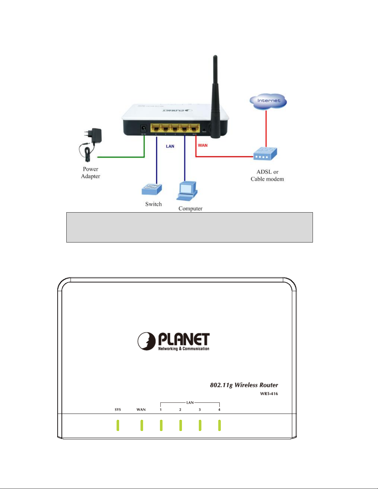
Note: ONLY use the power adapter supplied with the WRT-416. Otherwise, the product may be
damaged.
Note: If you want to reset WRT-416 to default settings, press and hold the Reset button over 5
seconds. And then wait for 10 seconds for WRT-416 restart.
2.3 LED Indicators
Page 9
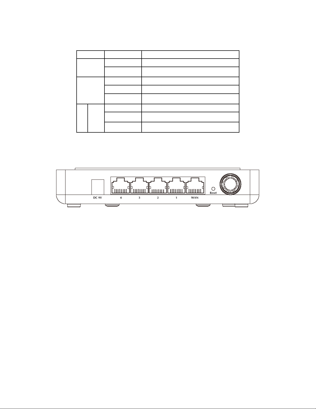
LED STATE MEANING
On Power is on SYS
Flashing The device is working
WAN
LAN 1~4
On WAN link is on
Flashing WAN activity
Off No connection
On Link is established
Flashing Packets are transmitting or receiving
Off No connection
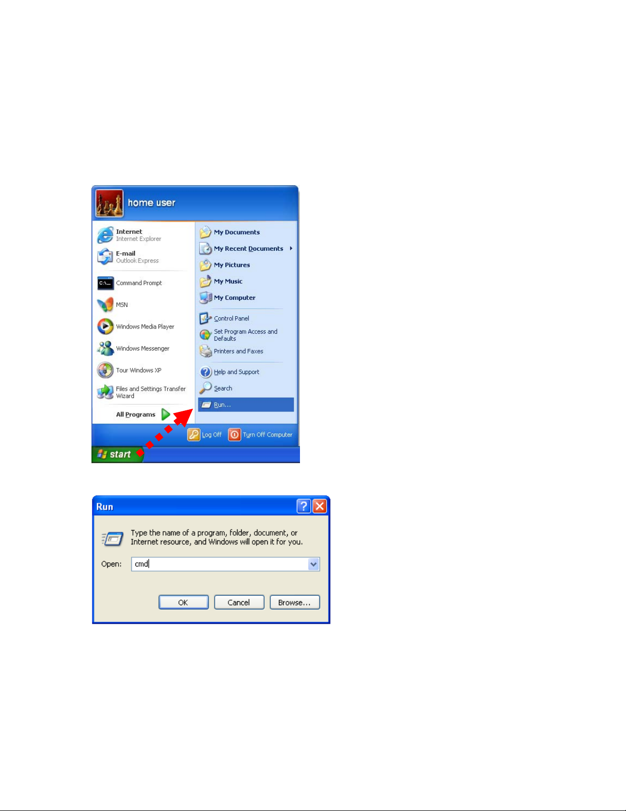
2.4 Back View
z Power (DC 9V): The power socket is where you plug in the power adapter. Please use the power
adapter provided with this wireless broadband router.
z LAN 1- 4: These 4 ports are used to connect the router to your PCs using Ethernet cables. Any of these
four ports can also serve as an uplink port to other network devices, such as another router or switch,
which allows you to extend your network.
z WAN: Connect your modem to your router using this port with your supplied Ethernet cable. This is the
only port you can use for this procedure. This enables your router to access the Internet. T he port
supports 10/100 Mbps as well as straight-through and crossover Ethernet cables.
z Default button: Reset the router to factory default settings (clear all settings) or reboot the router
function.
1. Set to factory defaults: Press this button and hold for over 5 seconds to restore all settings to
factory defaults,
2. Reboot the router: Press this button for less than 5 seconds to reboot.
z Antenna: The antenna used for wireless connections. You are able to rota te the anten na to gain the
best signal reception.
Page 10
Chapter 3 Configuring Local Networking
After you install your WRT-416, the TCP/IP settings should be set to obtain an IP address from a DHCP
server (WRT-416) automatically. To verify your IP address, please follow the steps below:
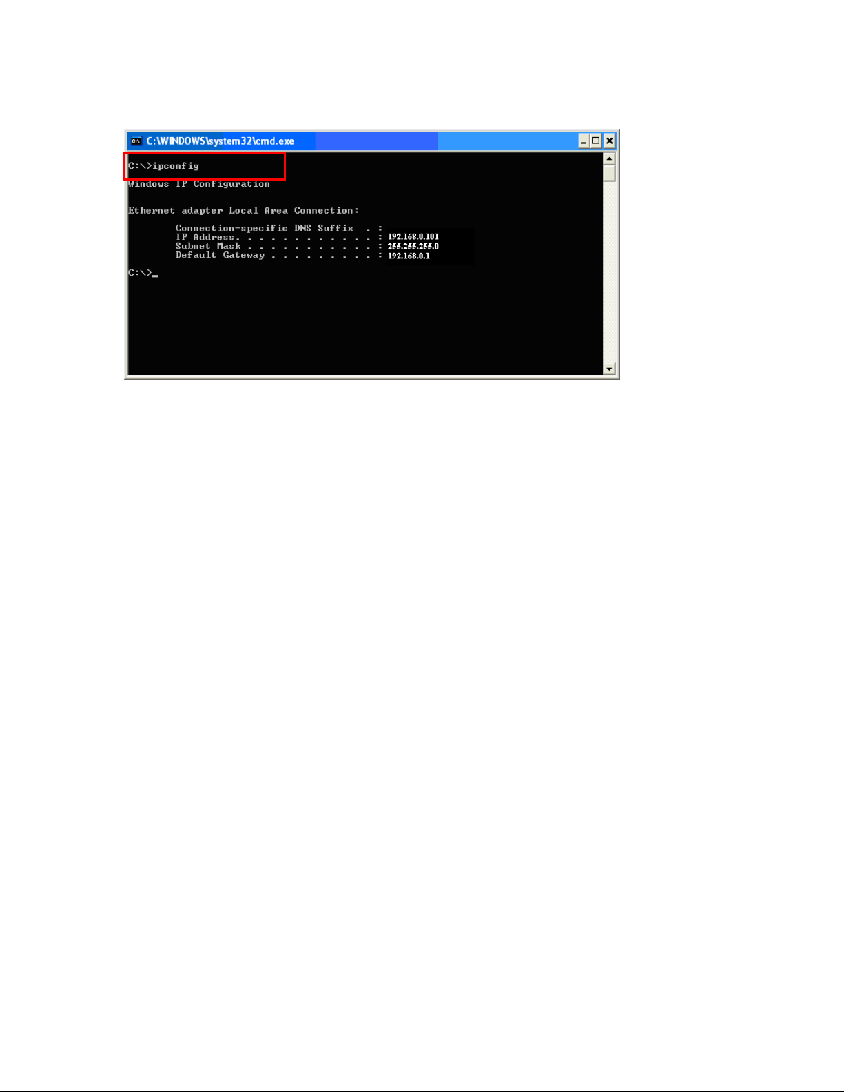
1. Click on Start > Run.
2. In the run box type “cmd” and click OK. (Windows VistaR users type cmd in the St art .Search box.)At the
prompt.
Page 11
3. Type “ipconfig” and press Enter. It will display the IP addr ess, subnet mask, and the default gateway of
adapter.
.
4. If the address is 0.0.0.0, check your adapter installation, security settings, and the settings on your router.
Some firewall software programs may block a DHCP request on newly installed adapters.
Assign a static IP address
If you are not using a DHCP capable gateway/router, or you need to assign a static IP address, please follow
the steps below:
1. - Windows Vista® - Click on Start > Control .Panel > Network .and .Internet
>Network .and .Sharing .Center > Manage Network Connections.
- Windows® XP - Click on Start > Control .Panel > Network Connections.
- Windows® 2000 - From the desktop, right-click My Network Places > Properties.
2. Right-click on the Local Area Connection which represents your network adapter and select Properties.
3. Highlight Internet .Protocol .(TCP/IP) and click Properties.
4. Click Use .the .following .IP .address and enter an IP address that is on the same subnet as your
network or the LAN IP address on your router.
Example: If LAN IP address of WRT-416 is 192.168.0.1, make your IP address 192.168.0.X where X is
a number between 2 and 99. Make sure that the number you choose is n ot in use on the network. Set
Default Gateway the same as the LAN IP address of your router (192.168.0.1).
Set Primary DNS the same as the LAN IP address of your router (192.168.0.1). The Secondary DNS is
not needed or you may enter a DNS server from your ISP.
5. Click OK twice to save your settings.
Page 12
Chapter 4 Web Configuration
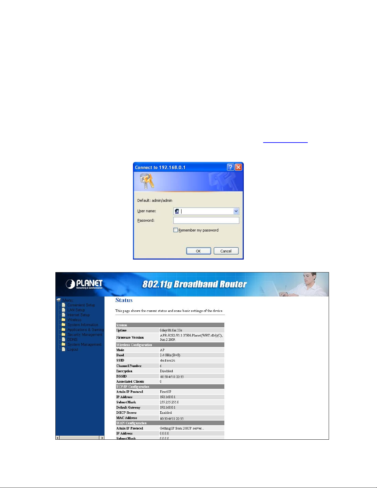
4.1 Web Login
WRT-416 with an assigned IP address allows you to monitor and configure via web browser (e.g., MS Internet
Explorer or Netscape).
1. Open your web browser.
2. Enter the IP address of your WRT-416 in the address field (default IP address is http://192.168.0.1).
3. Please enter your User Name and Password in the dialog box. Defau lt User Name and Password are
both “admin”. Click OK.
4. Then you will see the WRT-416 HOME screen as below.
Page 13

4.2 Convenient Setup
The Convenient Setup will guide you to configure access point for first time. Please follow the
Convenient Setup step by step.
Page 14

4.2.1 Operation Mode
z Gateway
In this mode, the device is supposed to connect to internet via ADSL/Cable Modem. The NAT is
enabled and PCs in four LAN ports share the same IP to ISP through WAN port. The connection
type can be setup in WAN page by using PPPOE, DHCP client, PPTP client or static IP.
z Bridge
In this mode, all ethernet ports and wireless interface are bridged together and NAT function is
disabled. All the WAN related function and firewall are not supported.
z Wireless ISP
In this mode, all ethernet ports are bridged together and the wireless client will connect to ISP
access point. The NAT is enabled and PCs in ethernet ports share the same IP to ISP through
wireless LAN. You must set the wireless to client mode first and connect to the ISP AP in
Site-Survey page. The connection type can be setup in WAN page by using PPPOE, DHCP client,
PPTP client or static IP. .
4.2.2 Time Zone
The Time Zone allows your router to base its time on the settings configured here, this will affect functions
such as Log entries and Firewall settings.
Page 15

z Time Zone Select
Select the time zone of the country you are currently in. The router will set its time based on your selection.
z NTP Server Address
You can manually assign time server address if the default time server dose not works.
4.2.3 LAN
The LAN Port screen below allows you to specify a private IP address for your router’s LAN ports as well as a
subnet mask for your LAN segment.
z IP Address
This is the router’s LAN port IP address (Your LAN clients default gateway IP address),the default is
192.168.1.1.
z Subnet Mask
Specify a Subnet Mask for your LAN segment, the default is 255.255.255.0
Page 16

4.2.4 WAN
Use the WAN Settings screen if you have already configured the Q uick Setup Wizar d section a nd you would
like to change your Internet connection type. The WAN Settings screen allows to specify the type of WAN port
connect you want to establish with your ISP. The WAN settings offer the following selections for the router’s
WAN port, Static IP, PPPoE, PPTP and DHCP Client.
z Static IP address
Your ISP has given you an IP address already
z DHCP Client
Your ISP will automatically give you an IP address. And then click on “Next”.
z PPPoE
Your ISP requires PPPoE connection
z PPTP
Your ISP requires you to use a Point-to-Poi nt Tunneling Protocol (PPTP) connection.
4.2.5 Wireless Basic Setting
Choose the “WAN Type”, “Wireless ISP” and “Apply” button for connecting to the wireless Access Point and
proceed to the manual’s relevant sub-section.
Page 17

z Mode
It allows you to set the AP to AP, Client, WDS or AP+WDS mode. The default is AP.
z Network Type
There are two type, infrastructure and hoc, the default is infrastructure
z SSID
This is the name of the wireless LAN. All the devices in the same wireless LAN should have the same
SSID, the default is default.
z Channel Number
The channel used by the wireless LAN. All devices in the same wireless LAN should use the same
channel.
4.2.6 Wireless Encryption
Supplies “None”. ”WEP” ,”WPA” ,”WPA2”. And ” WPA2 Mixed” five different encryption modes.
Page 18

z Encryption Mode
”None” means do not encrypt wireless data.
z WEP
There are two basic levels of WEP encryption, 64 bits and 128 bits, the more bits password have, the
better security wireless network is, at the same time the speed of wireless is more slower. If you select
WEP to encrypt your data, choose the bits of password, it should be 64 bits or 128 bits. Then choose the
format of password; it should be HEX or ASCII. The valid character for HEX format should be numbers
from 0 to 9 or letters from A to F.
HEX doesn’t support mixed letter and number mode. And ASCII supports mixed both letters and
numbers. By default, router provides four fields to input four groups of password, you can input all of
them or only one of them, and the client‘s password only need to match one group of password.
This is the name of the wireless LAN. All the devices in the same wireless LAN should have the same
SSID
z WPA (TKIP)
TKIP means “Temporal Key Integrity Protocol”, which incorporates Message Integrity Code (MIC) to
provide protection against hackers. Choose “Pre-Shared Key Format”
z WPA2(AES)
This use CCMP protocol to change encryption key frequently. AES can provide high leve l encryption to
enhance the wireless LAN security.
z WPA2 Mixed
This will use TKIP or AES based on the other communication peer automatically.
4.3 LAN Setup
The LAN Port screen below allows you to specify a private IP address for your router’s LAN ports as well as a
subnet mask for your LAN segment.
z IP Address
This is the router’s LAN port IP address (Your LAN clients default gateway IP address), the default is
192.168.0.1
Page 19

z Subnet Mask
Specify a Subnet Mask for your LAN segment
z Default Gateway
The IP address of Default gateway you obtained after connect to the Internet, if you haven’t connected
to Internet yet, this field is blank.
z DHCP Server
You ca n enable or disable the DHCP server. By enabling the DHCP server the router will automatically
give your LAN clients an IP address. If the DHCP is selected client, the router will get an IP address
from the other DHCP Server
z DHCP Client Range
You ca n select a particular IP address range for your DHCP server to issue IP addresses to your LAN
Clients.
z Domain name
Put into a name to mark your DHCP SERVER
z 802.1d Spanning tree
You can enable or disable the Spanning tree for your router
z Clone MAC address
Replace the LAN MAC address with the MAC address of that PC
4.4 Internet Setup
Configure the parameters for Internet network which connects to the WAN port of your Access Point. Here
you may cthe access method to static IP, DHCP, PPPoE or PPTP by click the item value of WAN Access type.
Page 20

z WAN Access Type:
1. Static IP address
Your ISP has given you an IP address already
2. DHCP Client
Your ISP will automatically give you an IP address.
3. PPPoE
Your ISP requires PPPoE connection.
4. PPTP
Your ISP requires you to use a Point-to- Point Tunneling Protocol (PPTP) connection.
z MTU
The MTU (Maximum Transmission Unit) setting specifies the largest packet size permitted for net work
transmission. Most DSL users should use the value 1492.You can set MTU manually, and you should
leave this value in the 1200 to 1500 range. If the value you set is not in accord with the value ISP
provide, it may causes some problems, such as fail to send Email, or fail to browse website. So if that
happen, you can contact your ISP for more information and correct your router’s MTU value.
z DNS
You ca n attain DNS automatically or specify a DNS server from DNS 1-3 that you wish to use.
z Clone MAC Address
Replace the WAN MAC address with the MAC address of that PC.
z Enable uPNP
Click the checkbox to enable uPNP function.
z Enable Web Server Access on WAN
Click the checkbox to enable web configuration from WAN side.
z Enable IPsec pass through on VPN connection
Click the checkbox to enable IPSec packet pass through.
z Enable PPTP pass through on VPN connection
Click the checkbox to enable PPTP packet pass through.
z Enable L2TP pass through on VPN connection
Click the checkbox to enable L2TP packet pass through.
Page 21

Chapter 5 Web Configuration
5.1 Web Login
The wireless router supplies the function of act as two AP simultaneously, but because the difference of
privilege, besides normal function of AP, the primary AP also has extra function for some advanced settings
and right management. So here you can manage and configure your primary AP.
z Disable Wireless LAN Interface
Click it will disable your Wireless LAN Interface. The Wireless Interface default is Enable.
z Band
It allows you to set the AP fix at 802.11b or 802.11g mode. You also can select B+G mode to allow the
AP select 802.11b and 802.11g connection automatically.
z Mode
It allows you to set the Wireless mode to AP, Client, WDS or AP+WDS mode. The default is AP mode.
z Network Type
There are two type, infrastructure and hoc, the default is infrastructure
z SSID
This is the name of the wireless LAN. All the devices in the same wireless LAN should have the same
SSID, the default SSID is default.
z Channel Number
The channel used by the wireless LAN. All devices in the same wireless LAN should use the same
channel.
Page 22

z Associated Clients
Click “Show Active Clients” button, then an “Active Wireless Client Table” will pop up. You can see the
status of all active wireless stations that are connecting to the access point.
z Enable Mac Clone
Click the “Enable MAC Clone” button will copy the MAC addr ess of your PC, that you are using to
configure the AP, to the WLAN MAC.
z Enable Universal Repeater Mode
To Enable Universal Repeater Mode, Acting as AP and client simultaneously
z SSID of extended Interface
Assign SSID’s name when enables Universal Repeater Mode.
5.2 Advanced Setting
You can set ad vanced wireless LAN parameters of this router. The parameters include Authentication Type,
Fragment Threshold, RTS Threshold, Beacon Interval, Preamble Type …… You sho uld not change these
parameters unless you know what effect the changes will have on this router.
z Authentication Type
There are two authentication types: "Open System" and "Shared Key". When you select "Open
System", wireless stations can associate with this wireless router without WEP encryption. When you
select "Shared Key", you should also setup WEP key in the "Encryption" page and wireless stations
should use WEP encryption in the authentication phase to associate with this wireless router. If you
select "Auto", the wireless client can associate with this wireless router by using any one of these t wo
authentication types.
Page 23

z Fragment Threshold
"Fragment Threshold" specifies the maximum size of packet during the fragmentation of data to be
transmitted.
z RTS Threshold
When the packet size is smaller the RTS threshold, the wireless router will not use the RTS/CTS
mechanism to send this packet.
z Beacon Interval
The interval of time that this wireless router broadcast a beacon. Beacon is used to synchronize the
wireless network.
z Data Rate
The “Data Rate” is the rate this access point uses to transmit data packets. The access point will use the
highest possible selected transmission rate to transmit the data packets.
z Preamble Type
The “Long Preamble” can provide better wireless LAN compatibility while the “Short Preamble” can
provide better wireless LAN performance
z Broadcast SSID
If you enable “Broadcast SSID”, every wireless station located within the coverage of this access point
can discover this access point easily. If you are building a public wireless network, enabling this feature
is recommended. Disabling “Broadcast SSID” can provide better security.
z IAPP
If you enable “IAPP”, it will allow wireless station roaming between IAPP enabled access points within
the same wireless LAN.
z 802.11g Protection
This is also called CTS Protection. It is recommended to enable the protection mechanism. This
mechanism can decrease the rate of data collision between 802.11b and 802.11g wireless stations.
When the protection mode is enabled, the throughput of the AP will be a little lower due to many of
frame traffic should be transmitted.
z IAPP
Click to enable or disable the IAPP function.
z 802.11g protection
Protect 802.11b user.
z WMM
Click Enabled/Disabled to init WMM feature.
z RF Output Power
To adjust transmission po wer level.
z Turbo Mode
Click to Enable/Disable turbo mode (Only apply to WLAN IC of Realtek).
Click “Save Setting” at the bottom of the screen to save the above configurations. You can now configure
other advance sections or start using the router.
5.3 Security
This Access Point provides complete wireless LAN security functions, include WEP, WPA (TKIP), WPA2
(AES), WPA2 Mixed. With these security functions, you can prevent your wireless LAN from illegal access.
Please make sure your wireless stations use the same security function.
Page 24

5.3.1 None
5.3.2 WEP only
When you select 64-bit or128-bit WEP key, you have to enter WEP keys to encrypt data. You can generate
the key by yourself and enter it. You can enter four WEP keys and select one of them as default key. Then the
router can receive any packets encrypted by one of the four keys
Page 25

z Key Length
You ca n select the WEP key length for encr yption, 64-bit or 128-bit. Larg er WEP key length will provide
higher level of security, but the throughput will be lower.
z Key Format
Y ou may to select ASCII Characters (alphanumeric format) or Hexadecimal Digits (in the "A-F", "a-f" and
"0-9" range) to be the WEP Key.
< For example: ASCII Characters: guest; Hexadecimal Digits: 12345abcde >
z Default Key
Select one of the four keys to encrypt your data. Only the key you select it in the "Default key" will take
effect.
z Key 1 - Key 4
The WEP keys are used to e ncryp t dat a transmi tted in the wire less ne twork. Fill the tex t box by fo llowing
the rules: 64-bit WEP: input 10-digit Hex values (in the "A-F", "a-f" and "0-9" range) or 5-digit ASCII
character as the encryption keys. 128-bit WEP: input 26-digit Hex values (in the "A-F", "a-f" and "0-9"
range) or 13-digit ASCII characters as the encryption keys.
Click “Save Setting” at the bottom of the screen to save the above configurations. You can now configure
other advance sections or start using the router (with the advance settings in place)
5.3.3 802.1x&WEP
IEEE 802.1x is an authentication protocol. Every user must use a valid account to login to this Access Point
before accessing the wireless LAN. The authentication is processed by a RADIUS server. This mode also
uses WEP to encrypt the data during communication.
z Authentication RADIUS Server port
The service port of the external RADIUS server.
z Authentication RADIUS Server IP address
The IP address of external RADIUS server.
z Authentication RADIUS Server IP Password
The password used by external RADIUS server.
For the WEP settings, please refer to section 5.3.2 “WEP only”.
Page 26

5.3.4 WPA
Wi-Fi Protected Access (WPA) is an advanced security standard. You can use a pre-shared key to
authenticate wireless stations and encrypt data during communication. It uses TKIP or CCMP (AES) to
change the encryption key frequently. So the encryption key is not easy to be broken by hackers. This can
improve security very much.
z WPA(TKIP)
TKIP can change the encryption key frequently to enhance the wireless LAN security.
z WPA(AES)
This uses CCMP protocol to change encryption key frequently. AES can provide high level encryption to
enhance the wireless LAN security.
z Personal (Pre-Shared Key)
You m ay select to select Passphrase (alphanumeric format) or Hexadecimal Di gits (in the “A-F”, “a-f”
and “0-9” range) to be the Pre-shared Key.
<For example: Passphrase: iamguest Hexadecimal Digits: 12345abcde>
z Enterprise (Radius)
You can use an external RADIUS server to authenticate wireless stations and provide the session key to
encrypt data during communication. It uses TKIP or CCMP(AES) to change the encryption key
frequently. This can improve security very much.
z RADIUS Server port
The service port of the external RADIUS server.
z RADIUS Server IP Address
The IP address of external RADIUS server.
z RADIUS Server Password
The password used by external RADIUS server.
Page 27

5.4 Access control
This wireless router provides MAC Address Control, which prevents the unauthorized MAC Addresses from
accessing your wireless network.
z Disable
Disable wireless access control
z Allow listed & Deny listed
Fill in the "MAC Address" and "Comment" of the wireless station to be added and then click "Add". Then
this wireless station will be added into the "Current Access Control List" below. If you find any issues
before adding it and want to retype again. Just click "delet e" and both "MAC Address" a nd "Comment"
fields will be cleared.
5.5 WDS Setting
Wireless Distribution System uses wireless media to communicate with other APs, like the Ethernet d oes. To
do this, you must set these APs in the same channel and set MAC address of other APs which you want to
communicate with in the table and then enable the WDS.
Page 28

Note:
First, you sho uld set this router work mode is “WDS” at “Wireless-basic settings”, then c lick “Enable
WDS”, pay attention, you must fill the MAC Address of another WDS working router.
5.6 Site survey
This function provides tool to scan the wireless network. If any Access Point or IBSS is found, you could
choose to connect it manually when client mode is enabled.
Page 29

Chapter 6 System Information
6.1 Status
This page shows the current status and some basic settings of evice.
6.2 Statistic
This page shows the packet counters for transmission and reception regarding to wireless, Ethernet LAN and
Ethernet WAN networks.
Page 30

Item Description
Wireless LAN
Sent Packets
Wireless LAN
Received Packets
Ethernet LAN
Sent Packets
Ethernet LAN
Received Packets
Ethernet WAN
Sent Packets
Ethernet WAN
Received Packets
Refresh Click the refresh the statistic counters on the screen.
It shows the statistic count of sent packets on the wireless LAN interface.
It shows the statistic count of received packets on the wireless LAN interface.
It shows the statistic count of sent packets on the Ethernet LAN interface.
It shows the statistic count of received packets on the Ethernet LAN interface.
It shows the statistic count of sent packets on the Ethernet WAN interface.
It shows the statistic count of received packets on the Ethernet WAN interface.
6.3 System Log
This page shows the current system log of the Broadband router. It displays any event occurred after system
start up, including view all information of system, wireless information, DoS attack information and so on.
Page 31

Chapter 7 Application & Gaming
7.1 Virtual Service
Use the Virtual Server function when you want different servers/clients in your LAN to handle different
service/Internet application type (e.g. Email, FTP, Web server etc.) from the Internet. Computers use
numbers called port numbers to recognize a particular service/Internet application type. The Virtual Server
allows you to re-direct a particular service port number (from the Internet/WAN Port) to a particular LAN
private IP address and its service port number. (See Glossary for an explanation on Port number)
z Enable Virtual Service
Enable Virtual Service
z IP Address
This is the LAN client/host IP address that the Public Port number packet will be sent to.
Note: You need to give your LAN PC clients a fixe d/static IP address for Virtual Server to work properly.
z Protocol
Select the port number protocol type (TCP, UDP or both). If you are unsure, then leave it to the default
both protocols.
z Port Range
This is the port number (of the above Private IP host) that the below Public Port number will be changed
to when the packet enters your LAN (to the LAN Server/Client IP)
z Comment
The description of this setting
Page 32

7.2 DMZ
If you have a local client PC that cannot run an Internet application (e.g. Games) properly from behind the
NAT firewall, then you can open the client up to unrestricted two-way Internet access by defining a DMZ Host.
The DMZ function allows you to re-direct all packets going to your WAN port IP address to a particular IP
address in your LAN. The difference between the virtual server and the DMZ function is that the virtual server
re-directs a particular service/Internet application to a particular LAN client/server, whereas DMZ re-directs all
packets (regardless of services) going to your WAN IP address to a particular LAN client/server.
Page 33

Chapter 8 Security management
8.1 Port Filtering
You ca n filter wired users by enabling this function; thus unauthorized users can not access the network.
z Enable Port Filtering
Enable port filtering
z Port Range
Add ports you want to control
z Protocol
Select the port number protocol type (TCP, UDP or both). If you are unsure, then leave it to the default
both protocol
z Comment
The description of this setting
8.2 IP Filtering
You ca n filter wired users by enabling this function; thus unauthorized users can not access the network.
Page 34

z Enable IP Filtering
Enable IP filtering
z Local IP Address
Add LAN IP address you want to control
z Protocol
Select the port number protocol type (TCP, UDP or both). If you are unsure, then leave it to the default
both protocol
z Comment
The description of this setting
8.3 MAC Filtering
You ca n filter wired users by enabling this function; thus unauthorized users can not access the network.
Page 35

z Enable MAC Filtering
Enable MAC filtering
z MAC Address
Add MAC address you want to control
z Comment
The description of this setting
8.4 URL Filtering
URL filter is used to deny LAN users from accessing the internet. Block those URLs which contain keywords
listed below.
Fill in “URL/Keyword” and then click “Save Settings”. You can enter the full URL address or the keyword of
the web site you want to block. If you find any typo bef ore adding it and want to retype again, just click
"Delete" and the field will be cleared.
8.5 URL Filtering
This page is used to enable and setup protection to prev ent attack by hacker’s program. It provides more
security for users.
Page 36

Page 37

8.6 DDNS
DDNS allows you to map the static domain name to a dynamic IP address. You must get an account,
password and your static domain name from the DDNS service providers. This router supports DynDNS, TZO
and other common DDNS service providers.
z Enable DDNS
Enable/Disable the DDNS function of this router
z Service Provider
Select a DDNS service provider
z Domain Name
Your static domain name that use DDNS
z User Name/Email
The account that your DDNS service provider assigned to you
z Password/Key
The password you set for the DDNS service account above
Page 38

Chapter 9 System Management
9.1 Time Zone Setting
You ca n maintain the system time by synchronizing with a public time server over the Internet.
Note:
For this settings, please refer to section 4.2.2 - “Time zone”.
9.2 Upgrade Firmware
This page allows you to upgrade the router’s firmware.
Page 39

z Select File
This tool allows you to upgrade the Broadband router ’s system firmware. To upgra de the firmware of
your Broadband router, you need to download the firmware file to your local hard disk, and enter that file
name and path in the appropriate field on this page. You can also use the Browse button to find the
firmware file on your PC.
Once you’ve selected the new firmware file, click “Upload” at the bottom of the screen to start the upgrade
process. (You may have to wait a few minutes for the upgrade to complete). O nce the upgrade is complete
you can start using the router.
9.3 Save/Reload Setting
This page allows you save current settings to a file or reload the settings from the file which was saved
previously. Besides, you could reset the current configuration to factory default.
9.4 Password
This page is used to set the account to access the web server of Access Point. Empty user name and
password will disable the protection.
Page 40

9.5 Logout
This function is used to logout.
Click “Save Settings” at the bottom of the screen to logout.
 Loading...