

Page 1

802.11n Wireless Broadband Router
WNRT-626
User’s Manual
Page 2

Copyright
2
Copyright © 2009 by PLANET Technology Corp. All rights reserved. No part of this publication may be
reproduced, transmitted, transcribed, stored in a retrieval system, or translated into any language or
computer language, in any form or by any means, electronic, mechanical, magnetic, optical, chemical,
manual or otherwise, without the prior written permission of PLANET.
PLANET makes no representations or warranties, either expressed or implied, with respect to the
contents hereof and specifically disclaims any warranties, merchantability or fitness for any particular
purpose. Any software described in this manual is sold or licens ed "as is". Should the programs
prove defective following their purchase, the buyer (and not this company, its distributor, or its dealer)
assumes the entire cost of all necessary servicing, repair, and any incidental or consequential
damages resulting from any defect in the software. Further, this company reserves the right to revise
this publication and to make changes from time to time in the conte nts hereof without obligation to
notify any person of such revision or changes.
All brand and product names mentioned in this manual are trademarks and/or register ed trademarks
of their respective holders.
Federal Communication Commission Interference Statement
This equipment has been tested and found to comply with the limits for a Class B digital device,
pursuant to Part 15 of FCC Rules. These limits are designed to provide reasonable protection against
harmful interference in a residential installation. This equipment generates, uses, and can radiate
radio frequency energy and, if not installed and used in accordance with the instructions, may cause
harmful interference to radio communications. However, there is no guarantee that interference will
not occur in a particular installation. If this equipment does cause harmful interference to radio or
television reception, which can be determined by turning the equipment off and on, the user is
encouraged to try to correct the interference by one or more of the following measures:
1. Reorient or relocate the receiving antenna.
2. Increase the separation between the equipment and receiver.
3. Connect the equipment into an outlet on a circuit different from that to which the receiver is
connected.
4. Consult the dealer or an experienced radio technician for help.
FCC Caution:
To assure continued compliance, (example-use only shielded i nterface cables when connecting to
computer or peripheral devices) any changes or modificat ions not expressly approved by the party
responsible for compliance could void the user’s authority to operate the equipment.
Page 3

This device complies with Part 15 of the FCC Rules. Operation is subject to the Following two
conditions: (1) This device may not cause harmful interference, and (2) this Device must accept any
interference received, including interference that may cause undesired operation.
Federal Communication Commission (FCC) Radiation Exposure
Statement
This equipment complies with FCC radiation exposure set forth for an uncontrol led environment. In
order to avoid the possibility of exceeding the F CC radio frequency expos ure limits, human proximit y
to the antenna shall not be less than 20 cm (8 inches) during normal operation.
R&TTE Compliance Statement
This equipment complies with all the requirements of DIRECTIVE 1999/5/CE OF THE EUROPEA N
PARLIAMENT AND THE COUNCIL OF 9 March 1999 on radio equipment and telecommunication
terminal Equipment and the mutual recognition of their conformity (R&TTE).
The R&TTE Directive repeals and replaces in the directive 98/13/EEC (Telecommunications Terminal
Equipment and Satellite Earth Station Equipment) As of April 8, 2000.
Safety
This equipment is designed with the utmost care for the safety of those who install and use it. However,
special attention must be paid to the dangers of electric shock and static electricity when working with
electrical equipment. All guidelines of this and of the computer manufacture must therefore be allowed
at all times to ensure the safe use of the equipment.
WEEE regulation
To avoid the potential effects on the environment and human health as a result of the
presence of hazardous substances in electrical and electronic equipment, end users of
electrical and electronic equipment should understand the meaning of the crossed-out
wheeled bin symbol. Do not dispose of WEEE as unsorted municipal waste and have to
collect such WEEE separately.
Revision
User’s Manual for PLANET 802.11N Wireless Router
Model: WNRT-626
Rev: 1.0 (Jan. 2009)
3
Page 4

TABLE OF CONTENTS
CHAPTER 1 INTRODUCTION...........................................................................................................6
1.1
P
ACKAGE CONTENTS
1.2
F
EATURES
1.3
S
PECIFICATION
CHAPTER 2 HARDWARE INSTALLATION / NETWORK SETUP..............................................8
2.1
H
ARDWARE INSTALLATION
2.2
LED I
2.3
NETWORK SETUP
CHAPTER 3 WEB LOGIN.................................................................................................................12
CHAPTER 4 QUICK SETUP.............................................................................................................14
4.1
T
IME ZONE
4.2
B
ROADBAND TYPE
CHAPTER 5 GENERAL SETUP.......................................................................................................25
5.1
S
YSTEM
...............................................................................................................................6
NDICATORS
...........................................................................................................................14
................................................................................................................................26
..............................................................................................................6
........................................................................................................................6
.....................................................................................................8
....................................................................................................................9
................................................................................................................10
...............................................................................................................15
5.2
WAN ....................................................................................................................................28
5.3
LAN.....................................................................................................................................35
5.4
W
IRELESS
5.5
QOS......................................................................................................................................49
5.6
NAT .....................................................................................................................................51
5.7
F
IREWALL
CHAPTER 6 WIRELESS CONFIGURATION ...........................................................................68
6.1
AP M
6.2
S
TATION-INFRASTRUCTURE MODE
6.3
AP B
6.4
AP B
6.5
AP B
6.6
U
NIVERSAL REPEATER MODE
6.7
S
ECURITY SETTING OF BRIDGE MODE
CHAPTER 7 STATUS....................................................................................................................80
.............................................................................................................................37
.............................................................................................................................60
ODE
.............................................................................................................................68
.......................................................................................69
RIDGE POINT TO POINT MODE
RIDGE POINT TO MULTI-POINT MODE
RIDGE
-WDS M
ODE
......................................................................................................73
......................................................................................71
...........................................................................72
...............................................................................................75
..................................................................................77
7.1
I
NTERNET CONNECTION
7.2
D
EVICE STATUS
7.3
S
YSTEM LOG
....................................................................................................................80
........................................................................................................................81
........................................................................................................80
4
Page 5

7.4
7.5
7.6
S
ECURITY LOG
A
CTIVE
S
TATISTICS
......................................................................................................................82
DHCP C
LIENT
.........................................................................................................83
............................................................................................................................83
CHAPTER 8 TOOLS......................................................................................................................84
8.1
C
ONFIGURATION TOOLS
8.2
F
IRMWARE UPGRADE
8.3
R
ESET
...................................................................................................................................86
CHAPTER 9 TROUBLESHOOTING..........................................................................................87
........................................................................................................84
............................................................................................................85
5
Page 6

Chapter 1 Introduction
Thank you for purchasing WNRT-626. This manual guides you on how to install and properly use the
WNRT-626 in order to take full advantage of its features.
1.1 Package Contents
Make sure that you have the following items:
•
WNRT-626 x 1
•
Stand x 1
•
Ethernet Cable x 1
•
Power Adapter x 1
•
CD-ROM (included user’s manual) x 1
•
Quick Installation Guide x 1
Note:
1.2 Features
z IEEE 802.11n (Draft 2.0) wireless technology compliant with 802.11b/gstandard
z Capable of up to 150Mbps data rate
z Supports Wi-Fi Protected Setup (WPS)
z Supports 64/128-bit WEP, WPA –TKIP(PSK), WPA2-AES(PSK), 802.1x
z Access Private LAN Servers from the Public Network
z AP / Station-Infrastructure / Bridge / WDS / Repeater modes supported
z Equipped with four LAN ports (10/100M) and one WAN port (10/100M), Auto-MDI/MDI-X
z Supports DHCP Server
z System status monitoring includes Active DHCP Client, Security Log and Device/Connection
z Web-based GUI for and Wizard setup for easily configuration
z Remote Management allows configuration and upgrades from a remote site
z Supported Internet types: Dynamic / Static IP / PPPoE / PPTP / L2TP / Telstra Big Pond
z MAC / IP filter access control, URL blocking ; SPI firewall + DoS prevention protection
z Supports UPnP function
If any of the above items are missing, please contact your supplier for support.
supported
Status
1.3 Specification
Standard IEEE 802.11b/g, 802.11n Draft 2.0, IEEE802.3u
11b mode: DSSS
Signal Type
Modulation
WAN Port 1 x 100Base-TX, Auto-MDI/MDI-X
LAN Port 4 x 100Base-TX, Auto-MDI/MDI-X
Antenna connector 1 x Fixed 3dBi Dipole Antenna
Data Encryption
Frequency 2.400GHz - 2.483GHz
Output Power
11g mode: OFDM
11n mode: OFDM, MIMO
802.11b: DBPSK, DQPSK, CCK
802.11g: BPSK, QPSK, 16QAM, 64QAM
802.11n: BPSK, QPSK, 16QAM, 64QAM
64 bit / 128 bit WEP, WPA-PSK, WPA, WPA2, 802.1x encryption
OFDM: 15 dBm ± 1 dBm
CCK: 17 dBm ± 1 dBm
6
Page 7

Data Rate
7
N Data Rate
Receiver Sensitivity
Sessions
LED Indicators PWR, WLAN, WAN * 1, LAN * 4
IEEE 802.11b: 11/5.5/2/1M
IEEE 802.11g: 54/48/36/24/18/12/9/6
Table (1)
11b CCK 1.0Mbps -94dbm 11b CCK 11.0Mbps -91dbm
11g OFDM 6Mbps -92dbm 11g OFDM 54Mbps -76dbm
11n 20MHz MCS7 : -72dbm 11n 40MH MCS7 : -70dbm
3000
Page 8
Chapter 2 Hardware Installation / Network Setup
Please follow the below instruction to build the wireless network connection between WNRT-626 and your
computers.
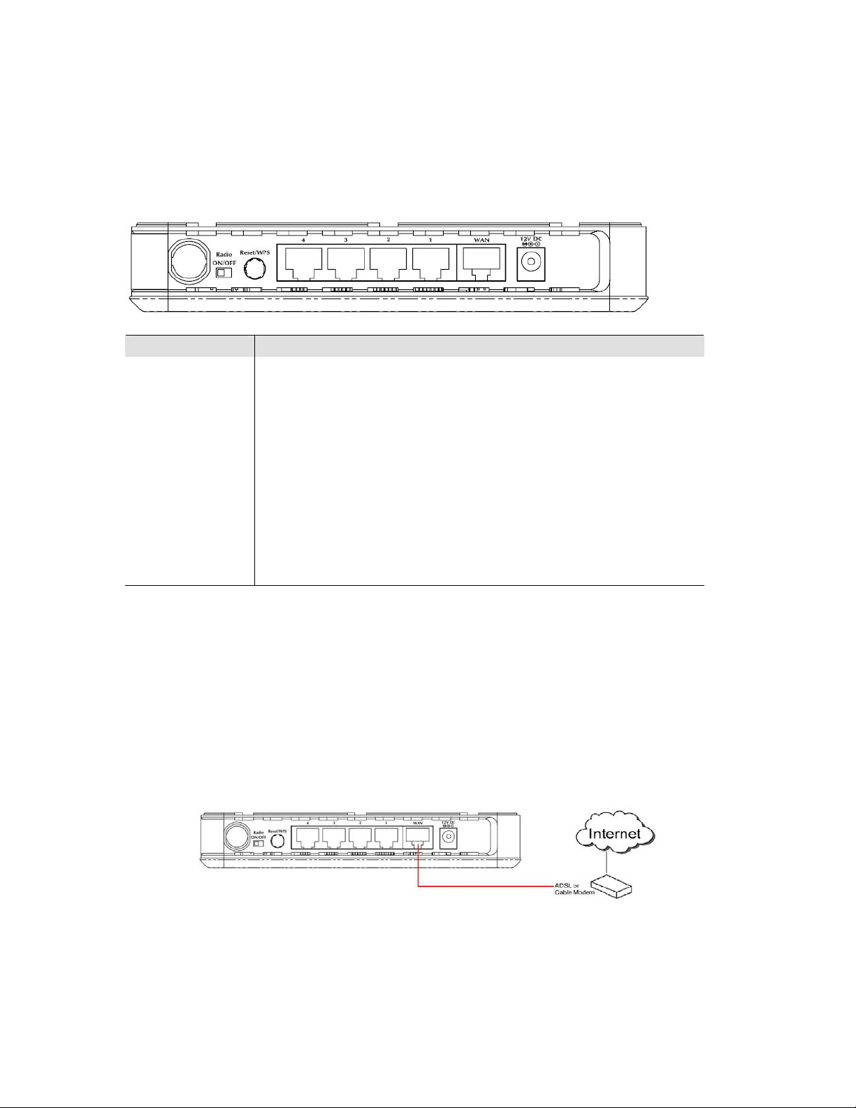
2.1 Hardware Installation
Item Name
Antenna
Description
Attached 3dBi dipole antenna.
Radio ON/OFF
Reset / WPS
1 - 4
WAN
Power
Switch the button to activate or deactivate the wireless functions.
Reset the router to factory default settings (clear all settings) or start WPS
function. Press this button and hold for 10 seconds to restore all settings to
factory defaults, and press this button for less than 5 seconds to start WPS
function.
Local Area Network (LAN) ports 1 to 4.
Wide Area Network (WAN / Internet) port.
Power connector, connects to power adapter.
1. Locate an optimum location for the WNRT-626. Th e b e s t place for your WNRT-626 is usually at
the center of your wireless network, with line of sight to all of your mobile stations.
2. Adjust the antennas of WNRT-626. Try to adjust them to a position that can best cover your wireless
network. The antenna’s position will enhance the receiving sensitivity.
3. Connect xDSL/Cable Modem to WAN port of WNRT-626. Usually, this cable would be provided with
your modem. If no cable was supplied with your modem, please use a RJ-45 Ethernet ca ble
4. Connect all of your network devices to LAN port of WNRT-626. Connect all your computers,
network devices (network-enabled consumer devices other than computers, like game console, or
switch / hub).Connect one of the LAN ports on WNRT-626 to your LAN switch/hub or a computer with
a RJ-45 cable.
8
Page 9
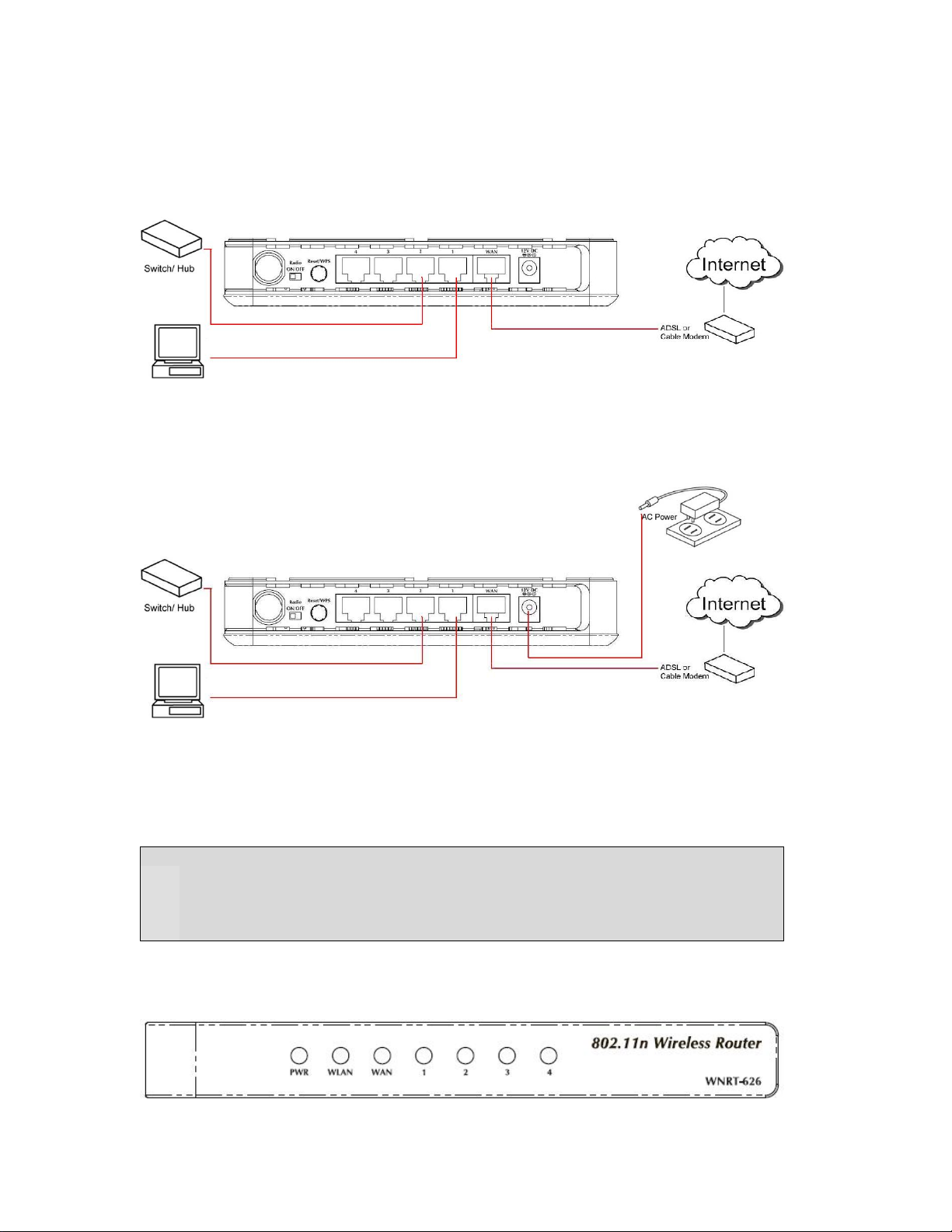
5. Plug in power adapter and connect to power source. After power on, WNRT-626 will start to
operate.
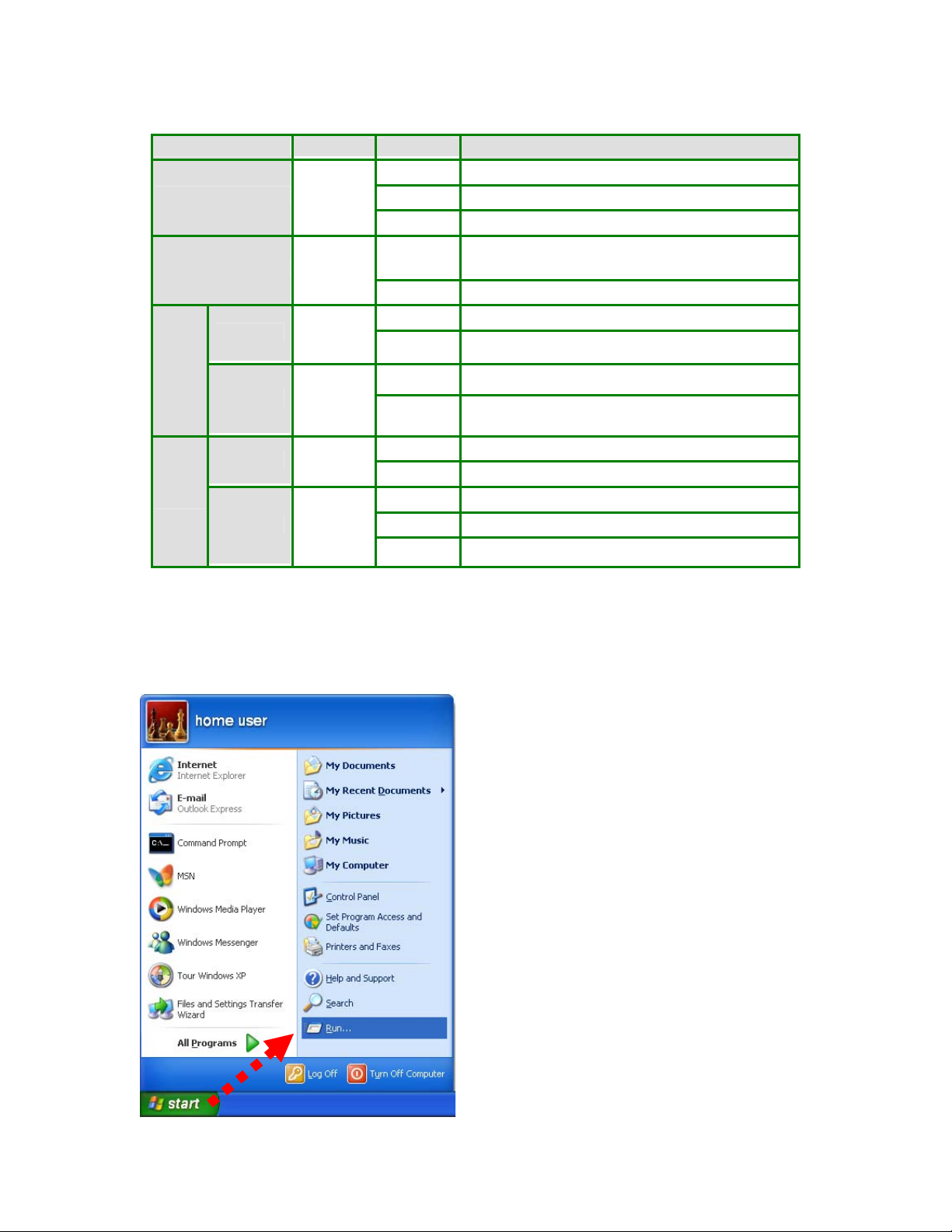
6. Please check all LEDs on the front panel. ‘PWR’ LED should be steadily on. WAN and LAN LEDs
should be on if the computer / network device connected to the respective port of the router is powered
on and correctly connected. If PWD LED is not on, or any LED you expected is not on, please recheck
the cabling, or jump to ‘Troubleshooting’ for possible reasons and solution.
Note:
1. ONLY use the power adapter supplied with the WNRT-626. Otherwise, the product may be
damaged.
2. If you want to reset WNRT-626 to default settings, press and hold the RST(reset) button over
30 seconds and release. And then wait for WNRT-626 restart.
2.2 LED Indicators
9
Page 10
LED Color STATE MEANING
On Device power on
PWR Green
WLAN Orange
100M Green
WAN
LNK/ACT Green
Off Device power off
Blinking During boot up procedure
Blinking
Off Wireless LAN is no function
On WAN port is connected at 100Mbps
Off WAN port is disconnected at 100Mbps
On Link is established
Blinking Packets are transmitting or receiving
Transmitting or receiving data through the Wireless
LAN
100M Green
LAN
LNK/ACT Green
On LAN is connected to 100Mbps device
Off LAN is disconnected to 100Mbps device
On Link is established
Blinking Packets are transmitting or receiving
Off LAN port is not connected
2.3 Network Setup
After you install your WNRT-626, the TCP/IP settings should be set to obtain an IP address from a DHCP
server (WNRT-626) automatically. To verify your IP address, please follow the steps below:
1. Click on Start > Run.
10
Page 11
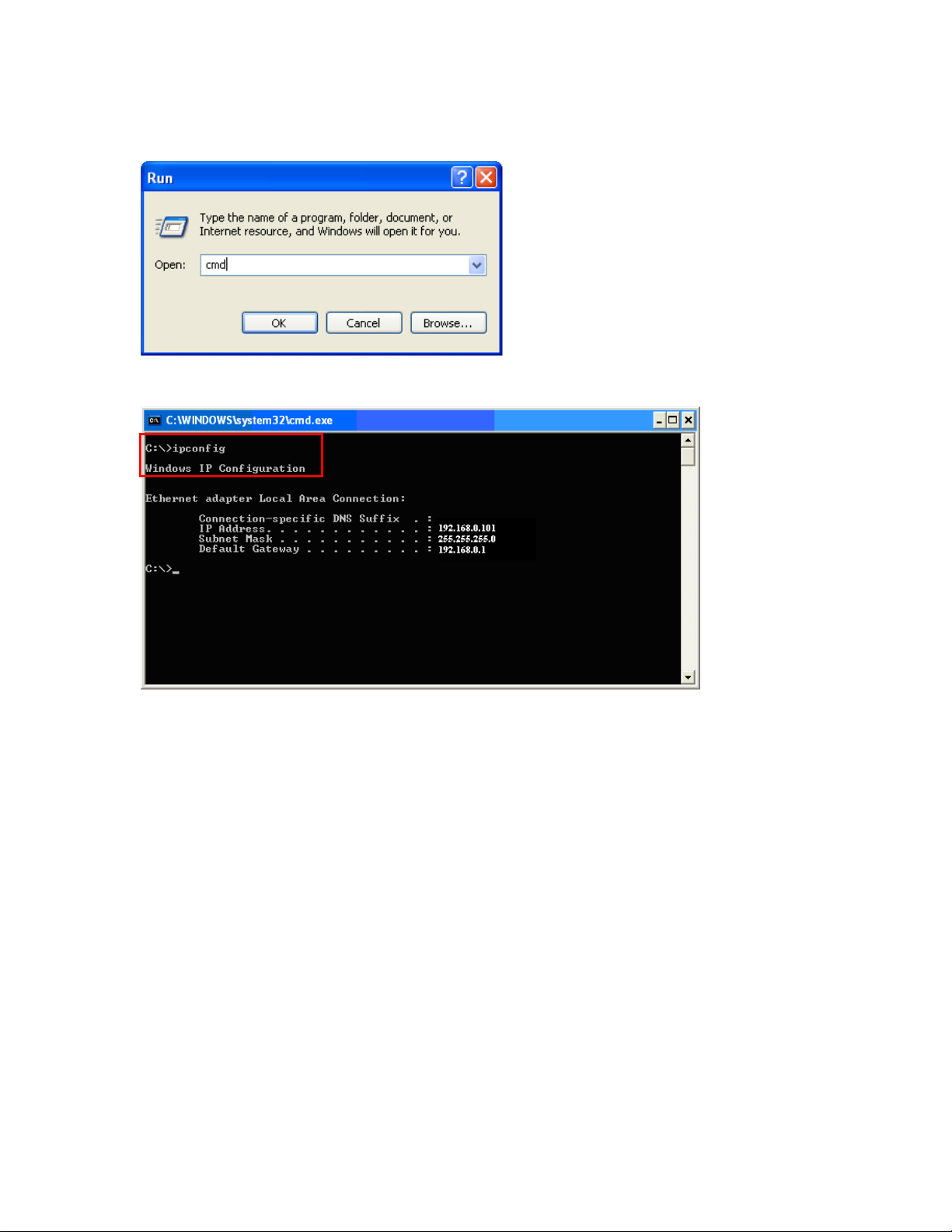
2. In the run box type “cmd” and click OK. (Windows VistaR users type cmd in the Start .Search box.)At the
prompt.
3. Type “ipconfig” and press Enter. It will display the IP address, subnet mask, and the default gateway of
adapter.
4. If the address is 0.0.0.0, check your adapter installation, security settings, and the settings on your router.
Some firewall software programs may block a DHCP request on newly installed adapters.
Assign a static IP address
If you are not using a DHCP capable gateway/router, or you need to assign a static IP address, please follow
the steps below:
1. - Windows Vista® - Click on Start > Control .Panel > Network .and .Internet
>Network .and .Sharing .Center > Manage Network Connections.
- Windows® XP - Click on Start > Control .Panel > Network Connections.
- Windows® 2000 - From the desktop, right-click My Network Places > Properties.
2. Right-click on the Local Area Connection which represents your network adapter and select Properties.
3. Highlight Internet .Protocol .(TCP/IP) and click Properties.
4. Click Use .the .following .IP .address and enter an IP address that is on the same subnet as your
network or the LAN IP address on your router.
Example: If LAN IP address of WNRT-626 is 192.168.0.1, make your IP address 192.168.0.X where X
is a number between 2 and 99. Make sure that the number you choose is not in use on the network. Set
Default Gateway the same as the LAN IP address of your router (192.168.0.1).
Set Primary DNS the same as the LAN IP address of your router (192.168.0.1). The Secondar y DNS is
not needed or you may enter a DNS server from your ISP.
5. Click OK twice to save your settings.
11
Page 12
2
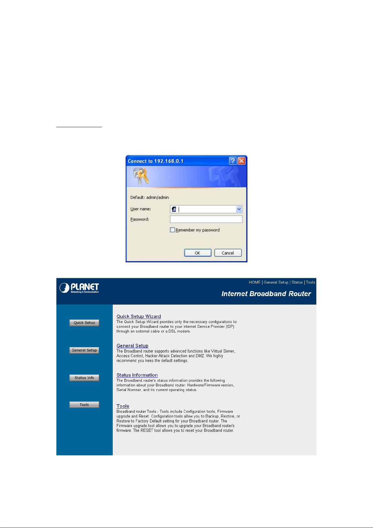
Chapter 3 Web Login
WNRT-626 with an assigned IP address allows you to monitor and configure via web browser (e.g., MS
Internet Explorer or Netscape).
1. Open your web browser.
2. Enter the IP address of your WNRT-626 in the address field (default IP address is
http://192.168.0.1
3. Please enter your User Name and Password in the dialog box. Default User Name and Password
are both “
4. Then you will see the WNRT-626 HOME screen as below.
).
admin
”. Click OK.
The left panel provides four options,
Quick Setup, General Setup, Status Information
1
and
Tools
.
Page 13

Section Description
Quick Setup
General Setup
Status Info
Tools
Select your Internet connection type and then inp ut the configurations needed
to connect to your Internet Service Provider (ISP).
This section contains configurations for the Broadband router’s advance
functions such as: Port Forwarding, Virtual Server, Access Control, Hacker
Attack Prevention, DMZ, Special applications and other functions to meet your
LAN requirements. You can also configure the wireless detail settings here.
This option provides you the system information, Internet Connectio n, Device
Status, Security Log and DHCP client Log information.
This option contains Configuration tools, Firmware Upgrade and Reset
functions.
13
Page 14
Chapter 4 Quick Setup
This section describes the basic configuration of the WNRT-626 and allows you to connect to Internet
easily.
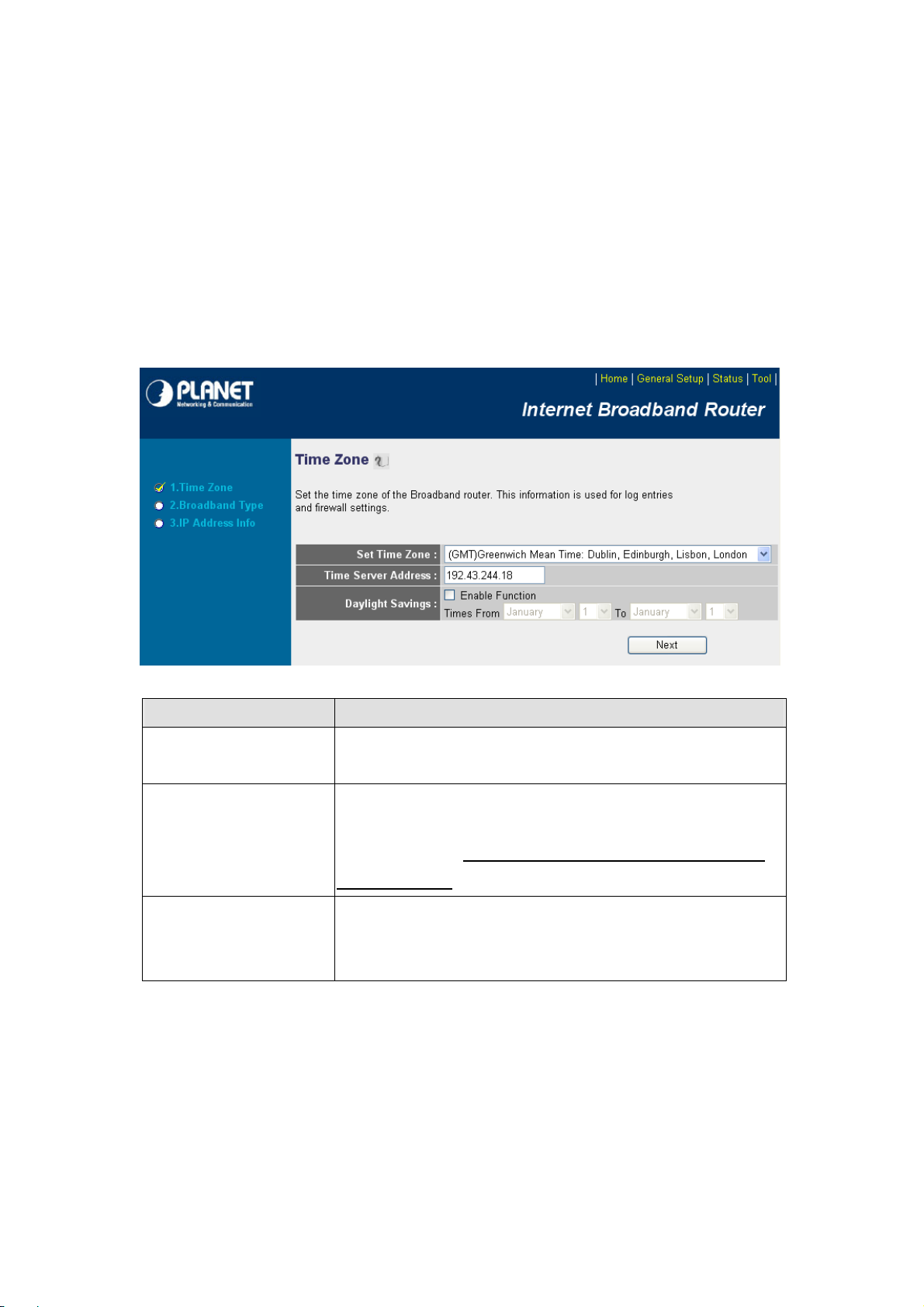
4.1 Time Zone
The time information is used for Log entries and Firewall settings. You can keep the default Time
Server address or set a new IP address for your router to synchronize its time. Click “Next” to continue.
Parameter
Set Time Zone
Time Server Address
Enable Daylight Savings
Click “Next” button to proceed to the next step.
Description
Select the time zone of the country you are currently in. The router will
set its time based on your selection.
Remain it as default or, you can manually assign an IP address of the
Time Server. The information of Timer Server can be found in the
following URL link: http://www.eecis.udel.edu/~mills/ntp/servers.html or
http://www.ntp.org.
The router can also take Daylight savings into account. To enable this
function, check/tick the “Enable Function” box and select which days this
function will work.
14
Page 15
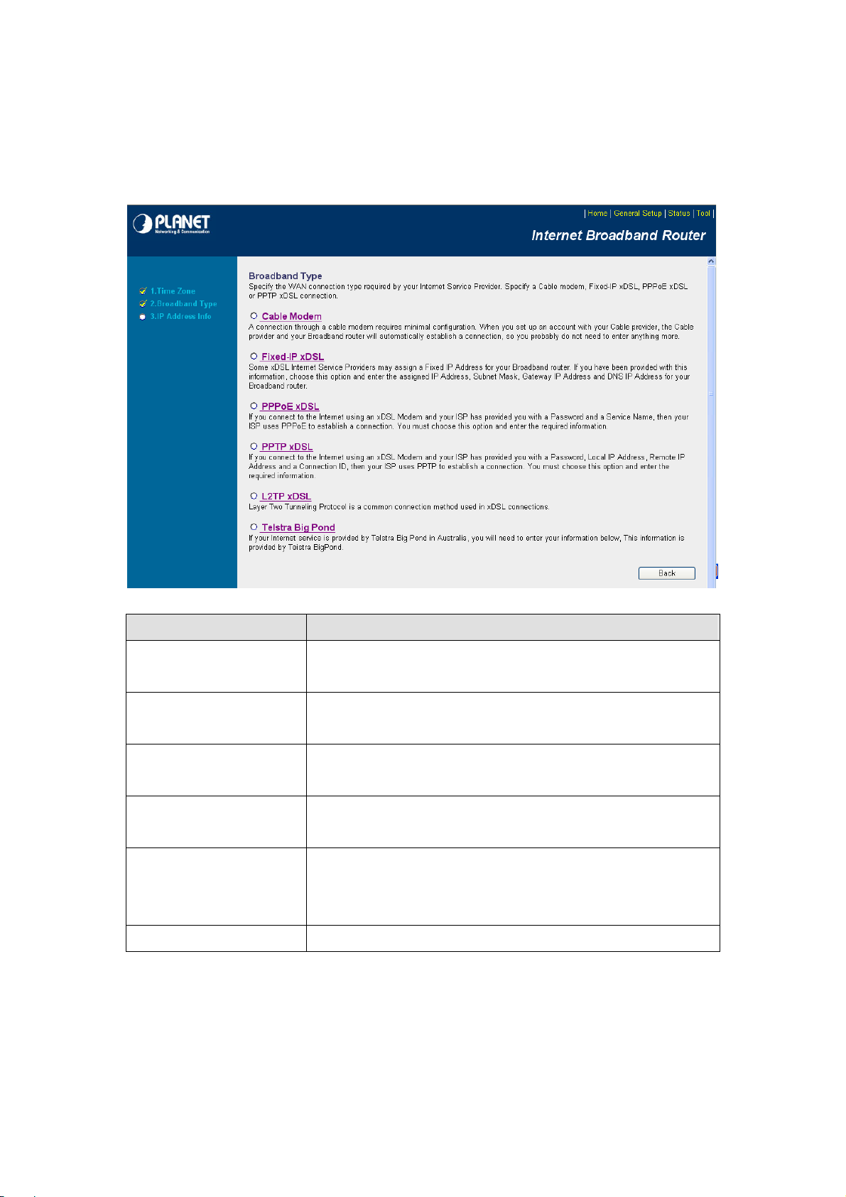
4.2 Broadband Type
Before establishing the Internet connection, please be sure to check with your ISP, and obtain all
necessary information from them.
Broadband
Cable Modem
Fixed-IP Xdsl
PPPoE xDSL
PPTP xDSL
L2TP XDSL
Telstra Big Pond This option is for Australia only. Please refer to section 4.2.6 for details.
Description
ISP will automatically give you an IP address. Please refer to section
4.2.1 for details.
ISP has given you a fixed IP address already. Please refer to section
4.2.2 for details.
ISP requires you to use a Point-to-Point Protocol over Ethernet (PPPoE)
connection. Please refer to section 4.2.3 for details.
ISP requires you to use a Point-to-Point Tunneling Protocol (PPTP)
connection.
This is not widely used. You need to know the PPTP Server address as
well as your name and password. Please refer to section 4.2.5 for
details.
Please refer to section 4.2.4 for details.
15
Page 16
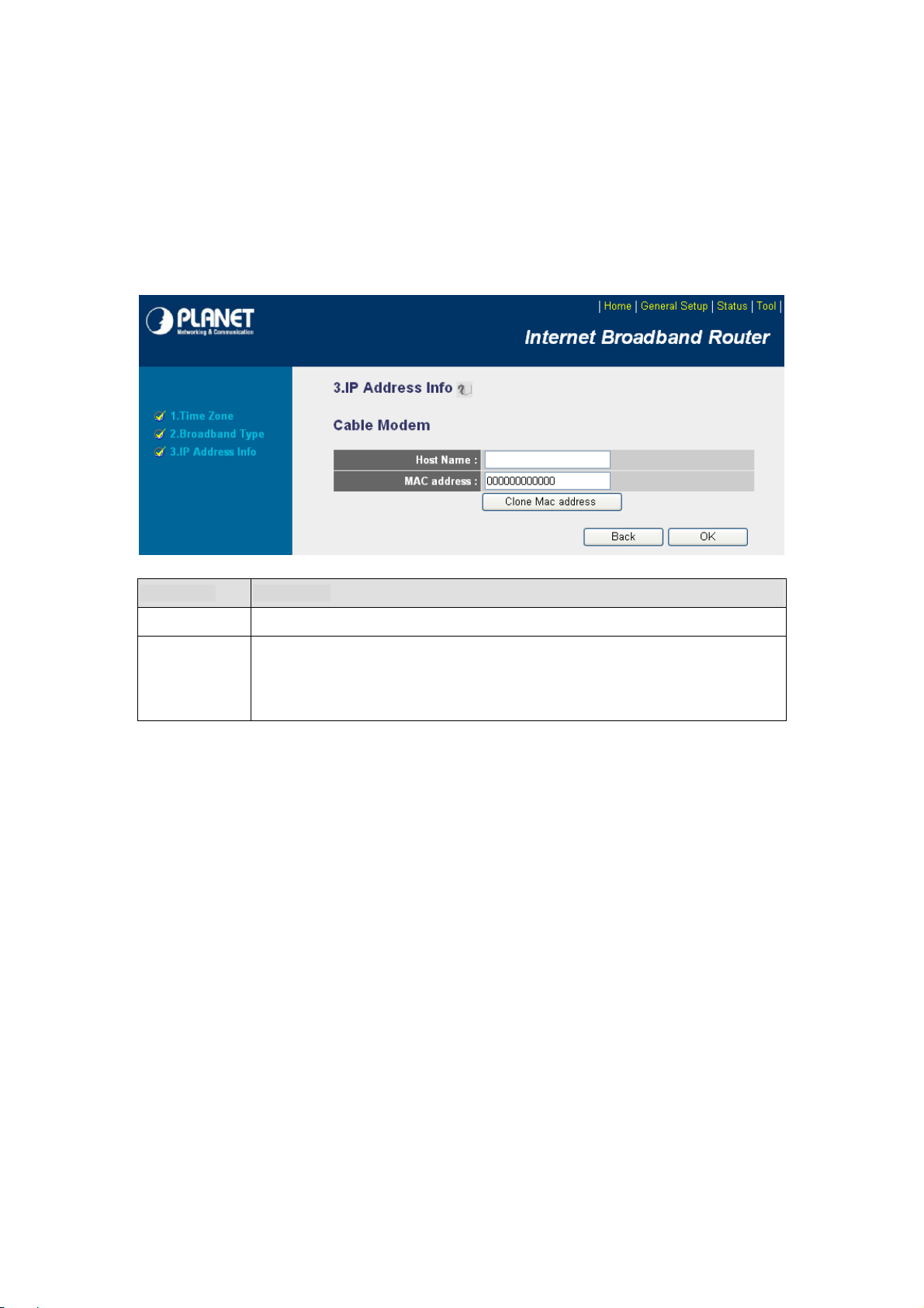
4.2.1 Cable Modem
With Cable Modem connection, the ISP will automatically give you an IP address. Some ISP may also
require you to fill in additional information such as Host Name and MAC address (see screen b el ow).
Note
: The Host Name and MAC address section is
does not require these settings for you to connect to the Internet.
optional
and you can skip this section if your ISP
Parameters Description
Host Name Type in the host name provided by your ISP if any; otherwise, just leave it blank.
To connect to Internet, your ISP will require a MAC address from your PC. Type in this
MAC Address
When the configuration finished, click “OK” to next step or click “Back” to previous step. After press
“OK”, you will see a web screen to prompt you the configurations save successfully. You may press
“Apply” to restart WNRT-626 with new configuration. Please refer to section 4.2.7 for more information
about this screen.
MAC address in this section or use the “
WAN port MAC address with the your PC’s.
Clone MAC Address
” button to replace the
16
Page 17

4.2.2 Fixed-IP xDSL
Select Fixed-IP xDSL if you’re ISP has given you a specified IP address. Your ISP should provide all th e
information required in this section.
Parameters Description
IP address assigned by your
The IP address that you’re ISP should provide you.
Service Provider
Subnet Mask Enter the Subnet Mask provided by your ISP (e.g. 255.255.255.0).
DNS Address The IP address of ISP’s DNS (Domain Name Service) Server.
Service Provider Gateway
The ISP’s IP address gateway.
Address
Please consult your local ISP about the information above. When the configuration finished please
click “OK” to next step or click “Back” to previous step. After press “OK”, you will see a web screen to
prompt you the configurations save successfully. Please refer to section 4.2.7 for the information of this
screen.
17
Page 18
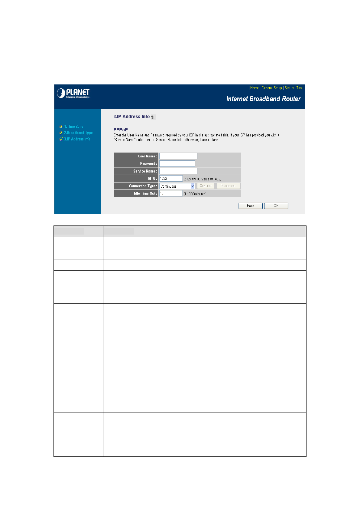
4.2.3 PPPoE xDSL
Select PPPoE if your ISP requires the PPPoE protocol for Internet connectivity. Your ISP should
provide all the information like user name, password required in this section.
Parameters Description
User Name Enter the User Name provided by your ISP for the PPPoE connection.
Password Enter the Password provided by your ISP for the PPPoE connection.
Service Name This is an optional parameter. Leave it blank unless your ISP requires it.
This is an optional parameter. You can spe cify the maximum size of transmission
MTU
Connection Type
packet to the Internet. The range of the MTU will be from 512 to 1492. You can also
consult you ISP for the optimal MTU as well. Default: 1392.
If you select “
breaks down and links again, the router wills auto-reconnect to the ISP.
If you select “
client in LAN want to use the Internet and keep connected until the WAN idle
timeout. The router will close the WAN connection if the time period that no one is
using the Internet exceeds the “
If you select “
manually from the Web user interface. The WAN connection will not disconnected
Continuous
Connect On Demand
Manual
”, the router will always connect to the ISP. If the WAN line
”, the router will auto-connect to the ISP when a
Idle Time
”, the router will connect to ISP only when you click “Connect”
”.
Idle Time
due to the idle timeout. If the WAN line breaks down and latter links again, the router
will not auto-connect to the ISP. Default:
You can specify an idle time threshold (mi nutes) for the WAN port. This means if no
packets have been sent (no one using the Internet) during this specified period, the
router will automatically disconnect the connection from your ISP.
Note:
This “idle timeout” function may not work due to abnormal activities of some
Continuous
.
18
Page 19
network application software, computer virus or hacker attacks from the Internet. For
example, some software sends network packets to the Internet in the background,
even when you are not using the Internet. So please turn off your computer when
you are not using it. This function also may not work with some ISP . So please make
sure this function can work properly, especially when your ISP charges you by time
used.
When the configuration finished, click “Apply” to next step or click “Cancel” to previous step. After press
“Apply”, you will see a web screen to prompt you the configurations save successfully. Please refer to
section 4.2.7 for the information of this screen.
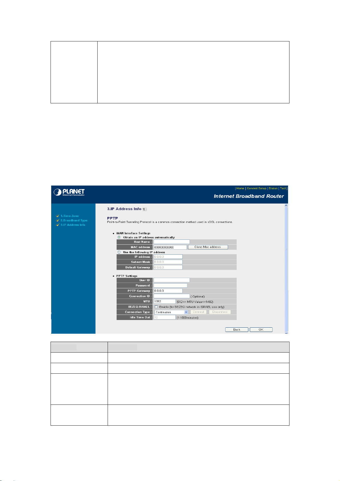
4.2.4 PPTP xDSL
Select PPTP if your ISP requires the PPTP protocol to connect to the Internet. Your ISP should provide
all the information required in this section.
Parameter Description
Obtain an IP address Select it if the ISP requires you to obtain an IP address by DHCP automatically.
Host Name Type in the host name provided by your ISP if any; otherwise, just leave it blank.
To connect to the Internet, your ISP will require a MAC address from your PC.
MAC Address
Use the following IP
address
Type in this MAC address in this section or use the “Clone MAC Address”
button to replace the WAN port MAC address with the MAC address of that PC.
Select it if the ISP provides you a static IP to connect to the PPTP server.
19
Page 20

IP Address
Subnet Mask Enter the Subnet Mask provided by your ISP (e.g. 255.255.255.0)
Gateway Enter the IP address of the ISP’s Gateway.
This is the IP address that your ISP has given you to establish a PPTP
connection.
User ID
Password Enter the Password provided by your ISP for the PPTP connection
PPTP Gateway
Connection ID This is the ID given by ISP. This is an optional parameter.
MTU
BEZEQ-ISRAEL Select this item if you are using the service provided by BEZEQ in Israel.
Connection Type
Enter the User Name provided by your ISP for the PPTP connection.
Sometimes called a Connection ID.
If your LAN has a PPTP gateway, enter that PPTP gateway’s IP address here. If
you do not have a PPTP gateway, enter the ISP’s Gateway IP address above.
This is an optional parameter. You can specify the maximum size of
transmission packet to the Internet. The range of the MTU will be from 512 to
1492. You can also consult you ISP for the optimal MTU as well. Default: 1392
If you select “
line breaks down and links again, the router shall auto- reconnect to the ISP.
If you select “
when a client in LAN wants to use the Internet and keep connected until the
WAN idle timeout. The router will close the WAN connection if the time period
that no one is using the Internet exceeds the “Idle Time”.
Continuous
Connect On Demand
”, the router will always connect to the ISP. If the WAN
”, the router will auto-connect to the ISP
If you select “
“Connect” manually from the Web user interface. The WAN connection will not
disconnect due to the idle timeout. If the WAN line breaks down and latter links
again, the router will not auto-connect to the ISP. Default:
You can specify an idle time thresh old (minutes) for the WAN port. This means
if no packets have been sent (no one using the Internet) throughout this
specified period, the router will automatically disconnect to with your ISP.
Note:
This “idle timeout” function may not work due to abnormal activ ities of
Idle Time
When the configuration finished please click “OK” to next step or click “Back” to previous step. After
press “OK”, you will see a web screen to prompt you the configurations save successfully. Please refer
to section 4.2.7 for the information of this screen.
some network application software, computer virus or hacker attacks from the
Internet. For example, some software sends network packets to the Internet in
the background, even when you are not using the Internet. So please turn off
your computer when you are not using it. This function also may not work with
some ISP. So please make sure this function can work properly, especially
when your ISP charges you by time used.
Manual
”, the router will connect to ISP only when you click
Continuous.
20
Page 21
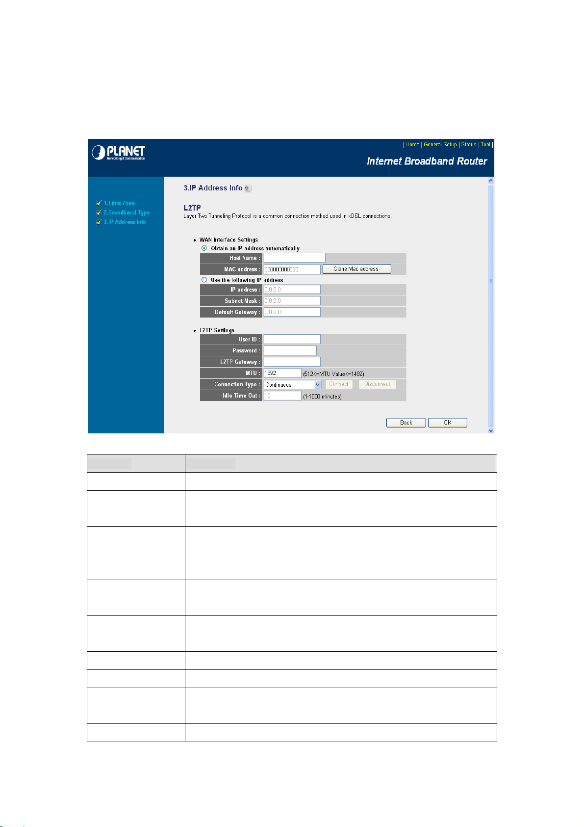
4.2.5 L2TP xDSL
Select L2TP if your ISP requires the L2TP protocol to connect to the Internet. Your ISP should provide
all the information required in this section.
Parameter Description
Obtain an IP address Select it if the ISP requires you to obtain an IP address by DHCP automatically.
Host Name
MAC Address
Use the following IP
address
IP Address
Subnet Mask Enter the Subnet Mask provided by your ISP (e.g. 255.255.255.0)
Gateway Enter the IP address of the ISP’s Gateway.
User ID
If your ISP requires a Host Name, type in the host name provided by your ISP;
otherwise, just leave it blank.
To connect to the Internet, your ISP will require a MAC address from your PC.
Type in this MAC address in this section or use the “Clone MAC Address”
button to replace the WAN port MAC address with the MAC address of that PC.
Select it if the ISP provides you a static IP to connect to the L2TP server.
This is the IP address that your ISP has given you to establish a L2TP
connection.
Enter the User Name provided by your ISP for the L2TP connection.
Sometimes called a Connection ID.
Password Enter the Password provided by your ISP for the L2TP connection
21
Page 22

L2TP Gateway
MTU
Connection Type
If your LAN has a L2TP gateway, enter that L2TP gateway’s IP address here. If
you do not have a L2TP gateway, enter the ISP’s Gateway IP address above.
This is an optional parameter. You can specify the maximum size of
transmission packet to the Internet. The range of the MTU will be from 1492 to
512. You can also consult you ISP for the optimal MTU as well. Default: 1392
If you select “
line breaks down and links again, the router shall auto- reconnect to the ISP.
If you select “
when someone wants to use the Internet and keep connected until the WAN
idle timeout. The router will close the WAN connection if the time period that no
one is using the Internet exceeds the “Idle Time”.
If you select “
“Connect” manually from the Web user interface. The WAN connection will not
disconnect due to the idle timeout. If the WAN line breaks down and latter links
again, the router will not auto-connect to the ISP. Default:
You can specify an idle time threshold (minutes) for the WAN port. This means
if no packets have been sent (no one using the Internet) throughout this
Continuous
Connect On Demand
Manual
”, the router will always connect to the ISP. If the WAN
”, the router will auto-connect to the ISP
”, the router will connect to ISP only when you click
Continuous.
specified period, then the router will automatically disconnect the connection
with your ISP.
Note:
This “idle timeout” function may not work due to abnormal activities of
Idle Time
When the configuration finished please click “OK” to next step or click “Back” to previous step. After press
“OK”, you will see a web screen to prompt you the configurations save successfully. Please refer to
section 4.2.7 for the information of this screen.
some network application software, computer virus or hacker attacks from the
Internet. For example, some software sends network packets to the Internet in
the background, even when you are not using the Internet. So please turn off
your computer when you are not using it. This function also may not work with
some ISP. So please make sure this function can work properly, especially
when your ISP charges you by time used.
4.2.6 Telstra Big Pond
Select Telstra Big Pond if you are live in Australia and your ISP requires this protocol to c onnect to th e
Internet. Your ISP should provide all the information required in this section.
22
Page 23
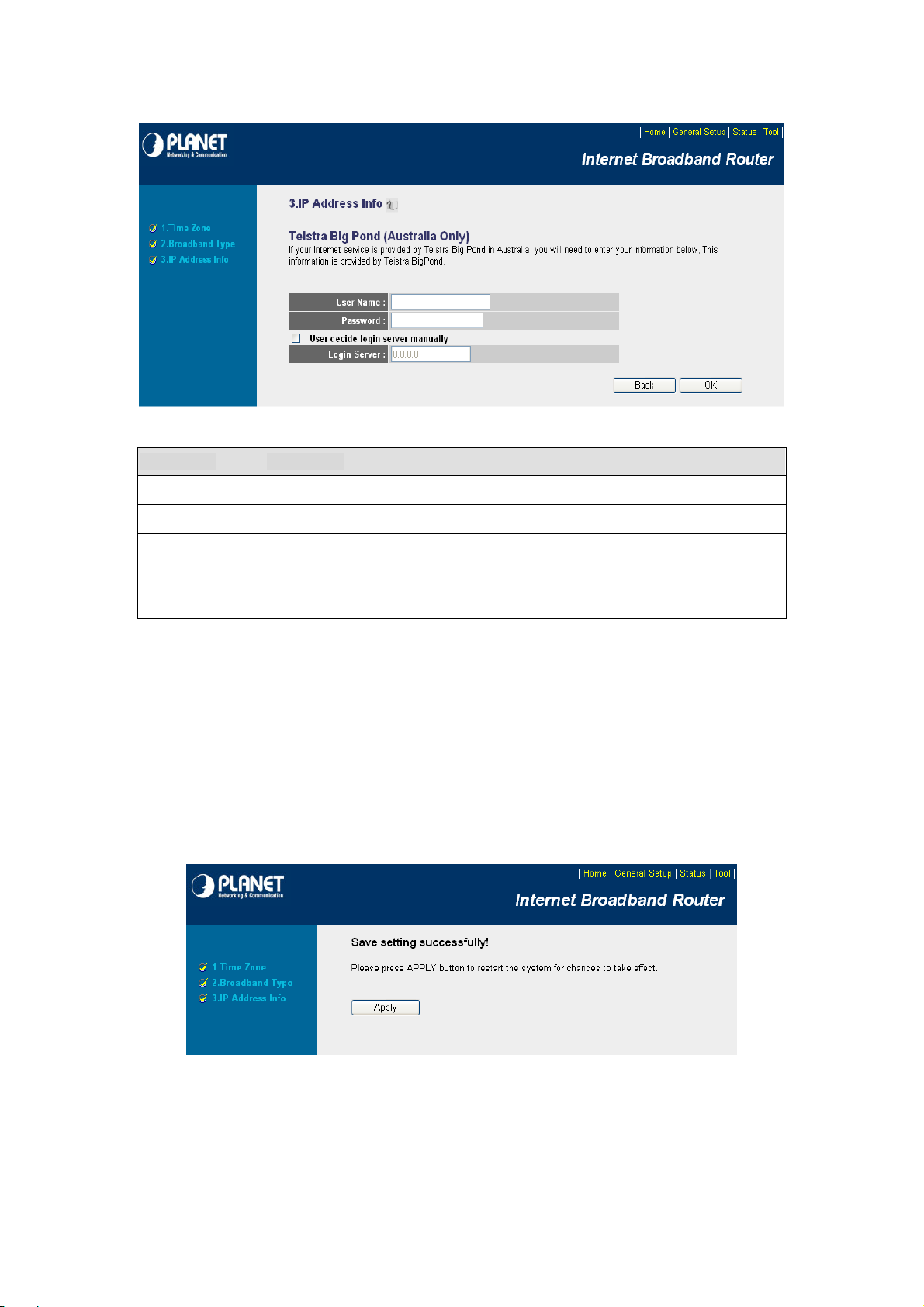
Parameters Description
User Name Enter the User Name provided by your ISP for the connection.
Password Enter the Password provided by your ISP for the connection.
User Decide login
server manually
Login Server Please enter the Login Server IP address here.
When the configuration finished please click “OK” to next step or click “Back” to previous step. After press
“OK”, you will see a web screen to prompt you the configurations save successfully. Please refer to
section 4.2.7 for the information of this screen.
If you ISP has provide the login server IP address to you, please check this box and
enter the Login Server IP address below.
4.2.7 Save Settings Successfully
When you press “OK” in above configuration, the settings will be saved and the screen appears as below.
Before WNRT-626 restart, the settings are saved, but not function yet. Press “Apply” to restart the
WNRT-626 for the change to take effect immediately.
23
Page 24

Please wait for 30 seconds for WNRT-626 restart. After restart procedure finished, please click “OK” to
return to HOME screen
.
24
Page 25
Chapter 5 General Setup
After click on the “General Setup” button at the main Page, you should see the screen below.
The General Setup contains advanced features that allow you to configure the router to meet the
network’s needs such as: Wireless, Port Forwarding, Virtual Server, Access Control, URL Blocking,
Special Applications, DMZ and other functions.
25
Page 26
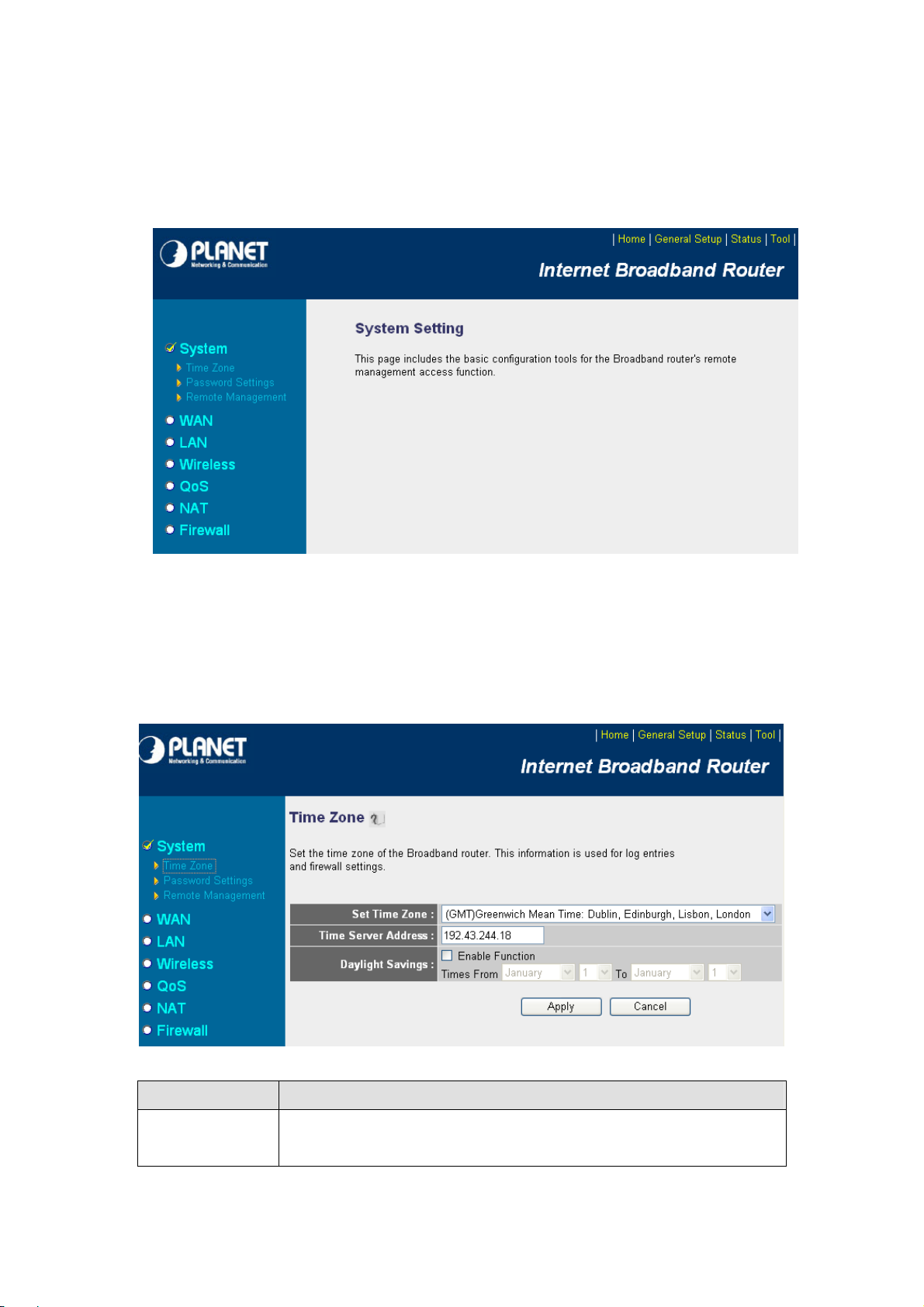
5.1 System
This section shows how to setup the Broadband router’s system Time Zone, Password and Remote
Management Administrator.
5.1.1 Time Zone
The Time Zone allows WNRT-626 to allocate its time on the settings configured here; it will affect log
display functions such as Security Log and Firewall settings.
Parameter Description
Select the time zone of the country you are currently in. The router will set its time
Set Time Zone
based on your selection.
26
Page 27
You can keep the default IP address or enter a new Time Server Address for this
Time Server Address
Daylight Savings
After the setup completed, please click “Apply” to save the settings. After press “Apply”, you will see a
web screen to prompt you the configurations save successfully. You may refer to section 4.2.7 for the
information of this screen.
device to synchronize its time. You can also refer to the web site
http://www.ntp.org to find a nearest time server.
The router can also take Daylight savings into account. Select the check box to
enable your daylight saving configuration. You can set the days that you wish to
start and stop daylight Savings Time.
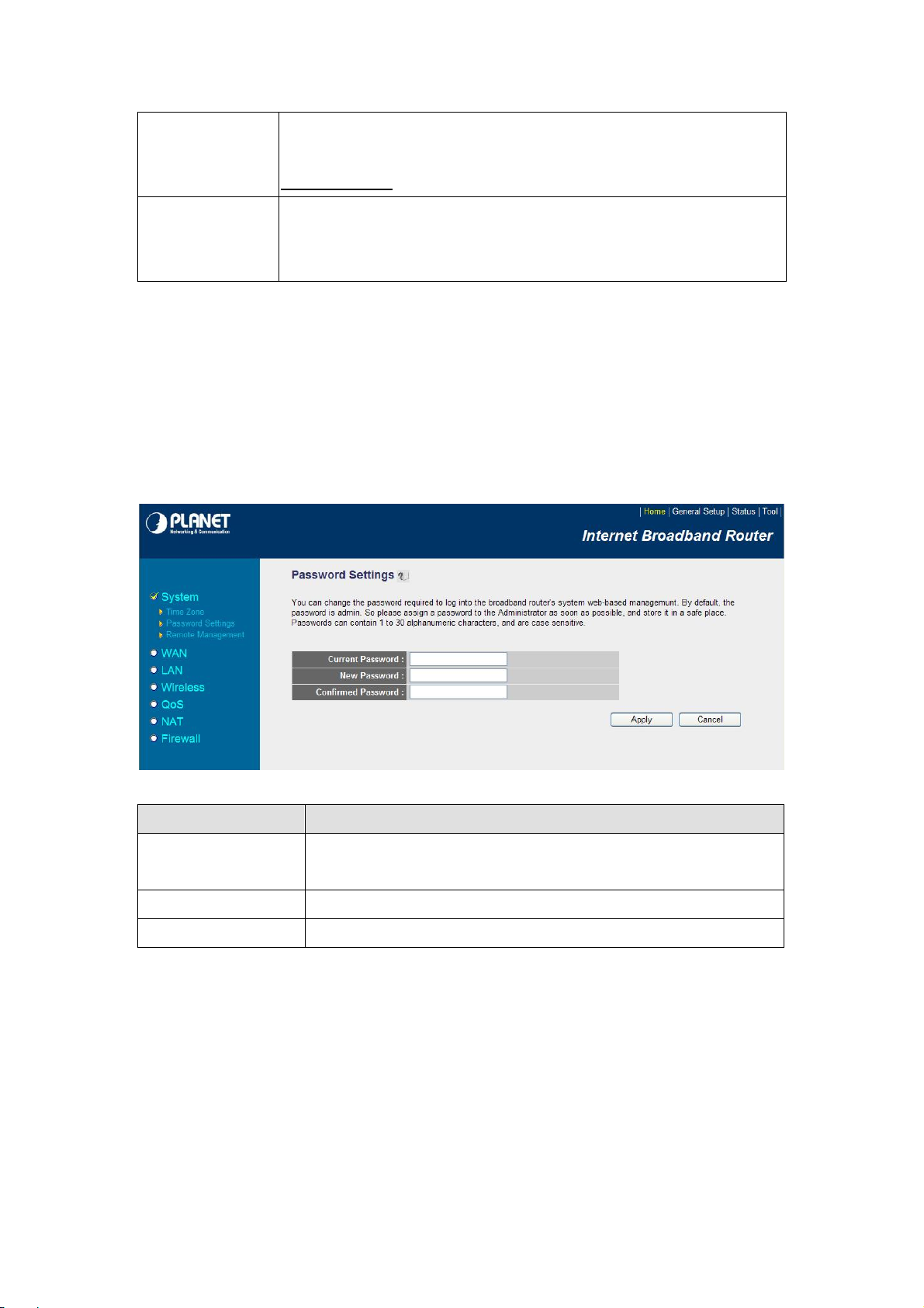
5.1.2 Password Setup
This screen allows you to change the management password.
Parameters Description
Current Password
New Password Enter your new password.
Confirmed Password Enter your new password again for verification purposes.
After the setup completed, please click “Apply” to save the settings. After press “Apply”, you will see a
web screen to prompt you the configurations save successfully. You may refer to section 4.2.7 for the
information of this screen.
Note
: If you forget the password, please reset the WNRT-626 to the factory default by press
button (on WNRT-626’s rear panel) over 30 seconds.
Enter your current password for the remote management administrator to
login to your Broadband router.
RST/WPS
27
Page 28

5.1.3 Remote Management
You can specify a Host IP address that can perform remote management from Internet.
Parameters Description
The IP address of the host on Internet that will have management / configuration
access to the Broadband router. Leave it to
0.0.0.0
means anyone can access the
router’s web-based configuration from any remote location.
Click the
Host Address
After the setup completed, please click “Apply” to save the settings. After press “Apply”, you will see a
web screen to prompt you the configurations save successfully. You may refer to section 4.2.7 for the
information of this screen.
Note:
must enter the router’s WAN IP address (e.g. 10.0.0.1) into your web-browser followed
by port number 8080, e.g. 10.0.0.1:8080 (see below). You’ll also need to know the
password set in the Password Setting screen in order to access the management
pages.
Enabled
When you want to access the web-based management from a remote site, you
box to enable the Remote Management function.
5.2 WAN
The WAN Settings screen allows you to specify the type of Internet connection. The WAN settings offer
the following selections for the router’s WAN port,
Telstra Big Pond
. Please select one of the connection types and click “More Configuration” button or
Dynamic IP, Static IP, PPPoE, PPTP, L2TP
, and
select the option on the left window for configuration.
28
Page 29

5.2.1 Dynamic IP
If Dynamic IP is selected, your ISP will automatically give you an IP address. Some ISP’s may also
require that you fill in additional information such as Host Name, Domain Name and MAC address.
Please refer to the section 4.2.1 for more settings of this option.
5.2.2 Static IP
If Static IP is selected, your ISP should provide all the information required in this screen . Please refer
to the section 4.2.2 for more settings of this option.
29
Page 30

5.2.3 PPPoE
Select PPPoE if your ISP requires PPPoE protocol to connect to the Internet. Your ISP should provide
all the information required in this section. Please refer to the section 4.2.3 to know the detail settings
of this option.
5.2.4 PPTP
Select PPTP if your ISP requires the PPTP protocol to connect to the Internet. Your ISP should provide
all the information required in this section. Please refer to section 4.2.4 for more settings of this option.
30
Page 31

5.2.5 L2TP
Select L2TP if your ISP requires the L2TP protocol to connect to the Internet. Your ISP should provide
all the information required in this section. Please refer to section 4.2.5 for more settings of this option.
31
Page 32

5.2.6 Telstra Big Pond
Select Telstra Big Pond if your ISP requires the Telstra Big Pond protocol to connect you to the Internet .
Telstra Big Pond protocol is used by the ISP in Australia. Your ISP should provide all the information
required in this section. Please refer to section 4.2.6 for more settings of this option.
5.2.7 DNS
A Domain Name System (DNS) server is like an index of IP addresses and Web addresses. If you type
a Web address into your browser, such as www.router.com, a DNS server will find that name in its
index and the matching IP address. Most ISPs provide a DNS server for efficiency and convenience. If
your Service Provider connects you to the Internet with dynamic IP settings, it is likely that the DNS
server IP address is provided automatically. However, if there is a DNS server that you would rat her to
use, please specify the IP address of that DNS server here.
32
Page 33

Parameters Description
DNS address
Secondary DNS Address
(optional)
After configuration complete, please click “Apply” button to save the configuration. Then you will see a
screen to prompt you the settings are saving successfully. You may press “Continue” for configure other
settings or “Apply” to restart WNRT-626 with new configuration. You may refer to secti on 4.2.7 for the
information of this screen.
This is the ISP’s DNS server IP address that they gave you; or you can
specify your own preferred DNS server IP address.
This is optional. You can enter another DNS server’s IP address as a
backup. The secondary DNS will be used when the above primary DNS
fails.
5.2.8 DDNS
DDNS allows you to map the static domain name to a dynamic IP address. You must get an account,
password and your static domain name from the DDNS service providers. This router supports
DynDNS and TZO.
33
Page 34

Parameters
Dynamic DNS
Provider Select a DDNS service provider. The default setting is “DynDNS”.
Domain name
Account / E-mail The account that your DDNS service provider assigned to you.
Password / Key The password you set for the DDNS servic e accou nt above.
After configuration complete, please click “Apply” button to save the configuration. Then you will see a
screen to prompt you the settings are saving successfully. You may press “Continue” for configure other
settings or “Apply” to restart WNRT-626 with new configuration. Please refer to sectio n 4.2.7 for more
information about this screen.
Description
Enable/Disable the DDNS function of this router.
Your static domain name that use DDNS.
34
Page 35

5.3 LAN
The LAN Port screen below allows you to specify a private IP address for your router’s LAN interface.
Parameters Description
LAN IP
IP Address
Subnet Mask
802.1d Spanning Tree
DHCP Server Enable or disable the DHCP Server.
DHCP Server
Lease Time
Please input the IP address of this router.
Designate the Access Point’s IP Address. This IP Address should be unique in
your network. The default IP Address is
Specify a Subnet Mask for your LAN segment. The Subnet Mask of the Access
Point is fixed and the value is
If it is enabled, this router will use the spanning tree protocol to prevent from
network loop happened in the LAN ports.
These settings are only available when ‘DHCP Server’ in ‘LAN IP’ section is
‘Enabled’
The DHCP Server will temporarily assign IP addresses to LAN clients. In the
Lease Time setting you can specify the time period that the DHCP Server lends
an IP address to your LAN client. The DHCP Server will change your LAN client’s
255.255.255.0
192.168.0.1
.
.
IP address when this time threshold period is reached.
35
Page 36

Y ou can designate a particular IP address range for your DHCP server to issue IP
Start IP/End IP
Domain Name You can specify the Domain Name for your Access Point.
Static DHCP Leases
Table
Enable Static DHCP
Leases
MAC Address
IP address Input the IP address you want to assign to this computer or network device.
Add
Clear If you want to remove all characters you just entered, please click it.
addresses to your LAN Clients. By default the IP range is from: Start IP
192.168.0.100
This function allows you to assign a static IP address to a specific computer
forever, so you don’t have to set the IP address for a computer, and still enjoy the
benefit of using DHCP server. Maximum 16 static IP addresses can be assigned
here.
Check this box to enable this function, otherwise uncheck it to disable this
function.
Input the MAC address of the computer or network device (total 12 characters,
with character from 0 to 9, and from a to f, like ‘001122aabbcc’)
After you inputted MAC address and IP address pair, click this button to add the
pair to static DHCP leases table.
to End IP
192.168.0.200
.
Note:
After you clicked ‘Add’, the MAC address and IP address mapping will be added to ‘Static DHCP
Leases Table’ section as below.
If you want to delete a specific item, please check the “Select” box of a MAC addr ess and IP
address mapping, then click ”Delete Selected” button; if you want to delete all mappings, click
“Delete All” button. If you want to deselect all mappings, click “Reset” button.
After configuration complete, please click “Apply” button to save the configuration. Then you will see a
screen to prompt you the settings are saving successfully. You may press “Continue” for configure other
settings or “Apply” to restart WNRT-626 with new configuration. Please refer to sectio n 4.2.7 for more
information about this screen.
36
Page 37

5.4 Wireless
This screen allows you to Enable/Disable WNRT-626 wireless function.
Parameters Description
Enable/Disable
After configuration complete, please click “Apply” button to save the configuration. Then you will see a
screen to prompt you the settings are saving successfully. You may press “Continue” for configure other
settings or “Apply” to restart WNRT-626 with new configuration. Please refer to sectio n 4.2.7 for more
information about this screen.
You can select to “
selected, please click “Apply” to make the settings effect.
Enable
” or “
Disable
” the Wireless interface. After
37
Page 38

5.4.1 Basic Settings
WNRT-626 supports not only Access Point function, but also provides Bridge and WDS mode. Please
Refer to
Default, WNRT-626 will work with AP mode.
“Chapter 6 Wireless Configuration
” know the details settings of wireless Basic Settings. In
5.4.2 Advance Settings
You should not change the parameters in this screen unless you know what effect the changes will
have on WNRT-626. Please click “Apply” to save the settings when configuration finished.
38
Page 39

Parameters Description
“Fragment Threshold” specifies the maximum size of packet during the
Fragment Threshold
RTS Threshold
Beacon Interval
DTIM Period
Data Rate
N Data Rate
Channel Width
fragmentation of data to be transmitted. If you set this value too low, it will result
in bad performance.
When the packet size is smaller the RTS threshold, the access point will not use
the RTS/CTS mechanism to send this packet.
The interval of time that this access point broadcast a beacon. Beacon is used to
synchronize the wireless network.
Set the DTIM period of wireless radio. Do not modify default value if you don’t
know what it is, default value is 3.
The Data Rate is the rate of data transmission for 802.11b/g clients. The
WNRT-626 will use the highest possible selected transmission rate to transmit
the data packets.
Set the wireless data transfer rate to a certain value for 802.11n clients. Since
most of wireless devices will negotiate with each other and pick a proper data
transfer rate automatically. Please refer to “N Data Rate Table” as below.
Set channel width of wireless radio. Do not modify default value if you don’t know
what it is, default setting is ‘Auto 20/40 MHz’.
Preamble type defines the length of CRC block in the frames during the wireless
Preamble Type
Broadcast ESSID
CTS Protection
TX Power
WMM
After configuration complete, please click “Apply” button to save the configuration. Then you will see a
communication. “
“
Long Preamble
If you enable “Broadcast ESSID”, every wireless station located within the
coverage of this access point can discover this WNRT-626 easily. If you are
building a public wireless network, enabling this feature is recommended. In
private network, disabling “Broadcast ESSID” can provide better security.
It is recommended to enable the protection mechanism. This mechanism can
decrease the rate of data collision between 802.11b and 802.11g wireless
stations. When the protection mode is enabled, the throughput of the AP will be a
little lower due to many of frame traffic should be transmitted.
Users can adjust the WNRT-626output power to 100%, 90%, 75% 50% 25% and
10%. In default, WNRT-626 will work with 100% output power.
The short of Wi-Fi Multi-Media, it will enhance the data transfer performance of
multimedia contents when they’re being transferred over wireless network.
Short Preamble
” can provide more reliable communication.
” is suitable for high traffic wireless network.
screen to prompt you the settings are saving successfully. You may press “Continue” for configure other
settings or “Apply” to restart WNRT-626 with new configuration. Please refer to section 4.2.7 for more
information about this screen.
39
Page 40

N Data Rate Table
MCS Index
0 7.2 15.0
1 14.4 30.0
2 21.7 45.0
3 28.9 60.0
4 43.3 90.0
5 57.8 120.0
6 65.0 135.0
7 72.2 150.0
8 14.444 30.0
9 28.889 60.0
10 43.333 90.0
11 57.778 120.0
12 86.667 180.0
13 115.556 240.0
14 130.000 270.0
15 144.444 300.0
HT20 HT40
Data rate (Mbps) @ 400ns GI
5.4.3 Security
WNRT-626 provides complete wireless LAN security functions, includes WEP, 802.1x, 802.1x
with WEP, WPA-PSK and WPA RADIUS. With these sec urity functions, you can prevent your
wireless LAN from illegal access. Please make sure your wireless stations use the same
security function. In default, the security function is “Disable”.
40
Page 41

5.4.3.1 WEP
When you select 64-bit or 128-bit WEP key, you have to enter WEP keys to encrypt data. You can
generate the key by yourself. You can enter four WEP keys and select one of them as default key.
Then the access point will just allow the clients that with the same encr yption keys connected. You
can use WEP encryption in “AP mode”, “Station-Ad Hoc mode”, “Station-Infrastructure mode” and
“AP Bridge-WDS mode”. If you would like to enable 802.1x Authentication also, please check the
“Enable 802.1x Authentication” and refer to section 5.4.3.2 for the detail of 802.1x settings.
Parameter Description
Encryption Please select “WEP” in this option.
You can select the 64 or 128-bit key to encrypt transmitted data. Larger
Key Length
Key Format
Default Tx Key
Encryption Key 1 - Key 4
WEP key length will provide higher level of security, but the throughput
will be lower.
You may select to select ASCII Characters (alphanumeric format) or
Hexadecimal Digits (in the “A-F”, “a-f” and “0-9” range) to be the WEP
Key.
Select one of the four keys to encrypt your data. Only the key you select
it in the “Default key” will take effect.
The WEP keys are used to encrypt data transmitted in the wireless
network. Fill the text box by following the rules below.
64-bit WEP: input 10-digit Hex values (in the “A-F”, “a-f” and “0-9”
range) or 5-digit ASCII character as the encryption keys.
128-bit WEP: input 26-digit Hex values (in the “A-F”, “a-f” and “0-9”
41
Page 42

2
range) or 10-digit ASCII characters as the encryption keys.
Check this box and another sub-menu will appear if you want to enable
Enable 802.1x Authentication
After configuration complete, please click “Apply” button to save the configuration. Then you will see a
screen to prompt you the settings are saving successfully. You may press “Continue” for configure other
settings or “Apply” to restart WNRT-626 with new configuration. Please refer to section 4.2.7 for more
information about this screen.
802.1
x
authentications with WEP encryption. You may refer to section
5.4.3.2 to enter the correct setting of the fields.
5.4.3.2 802.1X
IEEE 802.1x is an authentication protocol. Every user must use a valid account to login to this Access
Point before accessing the wireless LAN. The authentication is processed by a RADIUS server. This
mode only authenticates user by IEEE 802.1x, but it does not encryption the data during communication.
It is suggested to enable 802.1x and WEP at the same time.
Parameter Description
RADIUS Server IP address Please input the IP address of radius server here.
RADIUS Server Port Please input the port number of radius server here. Leave the defa ult
port setting or assign a new port number for this option.
RADIUS Server Password Please inp ut the port number of radius password here.
After configuration complete, please click “Apply” button to save the configuration. Then you will see a
screen to prompt you the settings are save successfully. You may pr ess “Continue” for configure other
settings or “Apply” to restart WNRT-626 with new configuration. Please refer to sectio n 4.2.7 for more
information about this screen.
5.4.3.3 WPA - PSK
Wi-Fi Protected Access (WPA) is an advanced securit y standard. You can use a pre-shared key to
authenticate wireless stations and encrypt data during communication. It uses TKIP or CCMP (AES) to
change the encryption key frequently. So the encryption key is not easy to be broken by hackers. This
can improve security very much.
4
Page 43

t
Parameter Description
Encryption Please select “WPA pre-shared key” in this option.
WPA (TKIP)
WPA Unicast
Cipher Suite
Pre-shared Key Format
Pre-shared Key
After configuration complete, please click “Apply” button to save the configuration. Then you will see a
screen to prompt you the settings are saving successfully. You may press “Continue” for configure other
WPA2 (AES)
WPA2 Mixed
TKIP can change the encryption key frequently to enhance the wireless
LAN security.
This use CCMP protocol to change encryption key frequently. AES can
provide high-level encryption to enhance the wireless LAN security.
This will use TKIP or AES based on the other communication peer
automatically.
You may select to select Passphrase (alphanumeric format) or
Hexadecimal Digits (in the “A-F”, “a-f” and “0-9” range) to be the
Pre-shared Key.
The Pre-shared key is used to authenticate and encrypt data
ransmitted in the wireless network. Fill the text box by following the
rules below.
Hex: input 64-digit Hex values (in the “A-F”, “a-f” and “0-9” range) or at
least 8 character pass phrase as the pre-shared keys.
settings or “Apply” to restart WNRT-626 with new configuration. Please refer to sectio n 4.2.7 for more
information about this screen.
5.4.3.4 WPA - RADIUS
You can use a RADIUS server to authenticate wireless stations and provide the session key to encrypt
data during communication. It uses TKIP or CCMP (AES) to change the encryption key frequently.
43
Page 44

Parameter Description
Encryption Please select “WPA RADIUS” in this option.
WPA (TKIP)
WPA Unicast
Cipher Suite
RADIUS Server IP Address Enter RADIUS Serer IP address.
RADIUS Server Port
RADIUS Server Password Please enter the password that is assigned in RADIUS Server.
After configuration complete, please click “Apply” button to save the configuration. Then you will see a
screen to prompt you the settings are saving successfully. You may press “Continue” for configure other
settings or “Apply” to restart WNRT-626 with new configuration. Please refer to sectio n 4.2.7 for more
information about this screen.
WPA2 (AES)
WPA2 Mixed
TKIP can change the encryption key frequently to enhance the wireless
LAN security.
This use CCMP protocol to change encryption key frequently. AES can
provide high-level encryption to enhance the wireless LAN security.
This will use TKIP or AES based on the other communication peer
automatically.
Leave the default port setting or assign a new port number for this
option.
44
Page 45

5
5.4.4 Access Control
WNRT-626 provides MAC Address Filtering, which prevents the unauthorized users from accessing your
wireless network.
Parameters Description
Enable Wireless
Access Control
Add MAC Address
to the control table
Remove MAC
address from the
table
Delete All If you want remove all MAC addresses from the list, just click this button.
Reset Click “Reset” will clear your current selections.
After configuration complete, please click “Apply” button to save the configuration. T hen you will see a
screen to prompt you the settings are saving successfully. You may press “Continue” for configure other
settings or “Apply” to restart WNRT-626 with new configuration. Please refer to sectio n 4.2.7 for more
information about this screen.
Enable or disable the MAC Address Filtering function.
In the bottom “New” area, fill in the “MAC Address” and “Comment” of the wireless
station and then click “Add”. Then this wireless station will be added into the “MAC
Address Filtering Table” above.
If you want to remove some MAC address from the “Current Access Control List”,
select the MAC addresses you want to remove in the list and then click “Delet e
Selected”.
4
Page 46

5.4.5 WPS
Wi-Fi Protected Setup (WPS) is the simplest way to build conn ection between wireless network clients
and this wireless router. You don’t have to select encryption mode and input a long encryption pass
phrase every time when you need to setup a wireless client, you on ly have to press a button on wireles s
client and router, and the WPS will do the rest for you.
This wireless router supports two types of WPS: Push-Button Configuration (PBC), and PIN code. If you
want to use PBC, you have to push a specific button on the wireless client to start WPS mode, and switch
this wireless router to WPS mode too. You can push RET/WPS button of this wireless router, or click
‘Start PBC’ button in the web configuration interface to do this. If you want to use PIN code, you can see
the setup as below.
Parameters Description
Enable WPS Check this box to enable WPS function, uncheck it to disable WPS.
Wi-Fi Protected
Setup Information
WPS Status
Self PIN code
SSID The SSID of this wireless router will be displayed here.
WPS-related system information will be displayed here.
If the wireless security (encryption) function of this wireless router is properly set,
you’ll see ‘Configured’ message here. If wireless security function has not been set,
you’ll see ‘unConfigured’.
This is the WPS PIN code of this wireless router. This code is useful when
WNRT-626 router sets as Enrollee, you need to fill this number into the web page of
the other device.
46
Page 47

7
Authentication
Mode
Passphrase Key
Device Configure
Config Mode: “Registrar”, “Enrollee”, pl ease see the setup step as below.
Configure via Push
Button
Configure via
PinCode
The wireless security authentication mode of this wireless router will be displayed
here.
Confirming your Identity Key Store Pass-phrase. It is allowed you to easily
remember the key what you may want to remember is that if the passphrase is
used,
Click ‘Start PBC’ to start Push-Button style WPS setup procedure. This wireless
router will wait for WPS requests from wireless clients for 2 minutes. The ‘WLAN’
LED on the wireless router will be steady on when this wireless router is waiting for
incoming WPS request.
Please input the PIN code of the other device you wish to connect, and click ‘Start
PIN’ button. The ‘WLAN’ led on the wireless router will be steady on when this
wireless router is waiting for incoming WPS request.(please see the detail as
below.)
PBC setup step:
1. Ensure you have set the security setting on WNRT-626 (as Registrar).
2. Click the WPS button on WNRT-626 (or the “Start PBC” button on the web interface of WNRT-626) and
the other device (supports PBC function) in 2 minutes.
3. WNRT-626 (Registrar) would send SSID and security key to the other device (Enrollee) through tunnel
to connect.
4. If you see the wireless client in the list, WPS-PBC setting is successful.
4
Page 48

PIN (as Registrar) setup step:
1. Select Config Mode: “Registrar” on WNRT-626.
2. Fill the PIN code of the other device (as Enrollee that support WPS-PIN setting) into the “configure via
Client Pincode” of WNRT-626.
3. Click the PIN buttons on WNRT-626 and the other device in 2 minutes.
4. If you see the wireless client in the list, WPS-PIN setting is successful.
PIN (as Enrollee) setup step:
1. Select Config Mode: “Enrollee” on WNRT-626.
2. Fill the PIN code of WNRT-626 into the other device (as Registrar).
3. Click the PIN buttons on WNRT-626 and the other device in 2 minutes.
4. If you see the wireless client in the list, WPS-PIN setting is successful.
** As the figure as above, just change two roles.
48
Page 49

5.5 QoS
Quality of Service (QoS) refers to the capability of providing better service to selected network traffic. The
primary goal of QoS is to provide priority including dedicated bandwidth, controlled jitter and latency
(required by some real-time and interactive traffic), and improved loss characteristics. When using this
feature, it is important to make sure the rules are not conflicted with each other.
Parameters Description
Check this box to enable QoS function, unselect this box if you don’t want to
Enable QoS
enforce QoS bandwidth limitations.
You can set the limit of total download bandwidth in kbits. To disable
Total Download Bandwidth
download bandwidth limitation.
You can set the limit of total upload bandwidth in kbits. To disable upload
Total Upload Bandwidth
bandwidth limitation.
When you want to add a new QoS rule, press this button and refer to
Add
instructions below to add a new QoS rule.
When you want to edit the existing QoS rule, press this button and refer to
Edit
instructions below to edit QoS rule.
Select the QoS rule which you would like to delete, press this button to
Delete Selected
delete.
When you want to delete all the QoS rules, you just need to press this
Delete All
button.
Move Up Select a QoS rule and press this button to assign higher priority.
Remove Down Select a QoS rule and press this button to assign lower priority.
Reset Click “Reset” to clear your current selections.
49
Page 50

After configuration complete, please click “Apply” button to save the configuration. Then you will see a
screen to prompt you the settings are saving successfully. You may press “Continue” for configure other
settings or “Apply” to restart WNRT-626 with new configuration. Please refer to sectio n 4.2.7 for more
information about this screen.
Add/Edit QoS Rule
You can assign packet classification criteria by its source IP range, destination IP range, traffic type,
protocol, and source port range and destination port range parameters. The parameters that you leave as
blank will be ignored. The priority of this rule will be applied to packets that match classification criteria of
this rule. You can limit bandwidth consumed by packets that match this rule or guar antee bandwidth
required by packets that match this rule.
After press Add or Edit button in QoS screen, you will see the web screen below for user to setup their
QoS rule.
Parameters Description
Rule Name Please give a name to the QoS Rule
You can limit the maximum bandwidth consumed by this rule by selecting
“Maximum”. You also can reserve enough bandwidth for this rule by
selecting “Guarantee”. The unit of bandwidth is Kbps. When we download
Bandwidth
data from Internet, the unit of download screen shows is KBps. 1KBps is
equal to 8Kbps. When you enter the bandwidth, please make sure the
number you enter is correct. For example, if you want to limit users
download speed to 50KBps from Internet, you will need to enter 400Kbps in
the configuration.
50
Page 51

Local IP Address
Please enter the IP address of the local PC. If there is only one IP address
you want to assign, please fill IP address in these two spaces.
Please input the range of local (source) port number that will be affected by
this rule. If you want to apply this rule on port 80 to 90, please input ’80-90’; if
Local Port Range
you want to apply this rule on a single port, just input the p ort number, like
‘80’; if you want to apply this rule none assigned port, must input the port
number ‘1-65535’.
Please enter the IP address of the PC from remote site. If you don’t assign,
Remote IP Address
please let it blank.
Please input the range of local (source) port number that will be affected by
this rule. If you want to apply this rule on port 80 to 90, please input ’80-90’; if
Remote Port Range
you want to apply this rule on a single port, just input the p ort number, like
‘80’; if you want to apply this rule none assigned port, must input the port
number ‘1-65535’.
Select the traffic type of the packets that this rule will apply to. We list some
popular applications here to ease the configuration. You also can get the
Traffic Type
same result by using other parameters, for example source or destination
port number, if you are familiar with the application protocol.
Protocol Please select the protocol TCP or UDP in the list.
After configuration complete, please click “Save” to save the settings. Or you may press “Reset” to clear
the settings to enter again.
5.6 NAT
Network Address Translation (NAT) allows multiple users at your local site to access the Internet via a
single legal IP Address. NAT provides Firewall protection fr om hacker attacks and has the fle xibility to
allow you to map Private IP Addresses to Public IP Addresses for key services such as Websites and
FTP. If NAT is disabled, all LAN side workstations must have legal IP addresses for Internet access. If
the router is used for routing application, not for Internet access, the NAT function can be disabled.
51
Page 52

Parameters Description
You can select to enable or disable the NAT function. If you choose the
Enable or Disable NAT
module function
After configuration complete, please click “Apply” button to save the configuration. Then you will see a
screen to prompt you the settings are saving successfully. You may press “Continue” for configure other
settings or “Apply” to restart WNRT-626 with new configuration. Please refer to sectio n 4.2.7 for more
information about this screen.
disable, the NAT sub-function will just let you to use the function of Static
Routing setting as well as the fast NAT mode also cannot be used even it is
in the status of enable. After selected, please click “Apply” to make the
settings effect.
5.6.1 Static Routing
After you disable NAT mode, you can enable Static Routing to turn off NAT function of this router and let
this router forward packet by your routing policy.
52
Page 53

Parameters Description
Enable Static Routing
Destination LAN IP
Subnet Mask
Default Gateway
Hop Count Input which hop count yo u want to apply to this configuration.
Interface Select the interface which you would like to use (LAN / WAN).
Add
Reset Click “Reset” will clear your current settings to allow you to enter again.
Current Static Routing Table
Delete Selected
Check this box to enable Static Routing function, unselect this box if you
don’t want to turn off NAT function of this router.
Type the Destination LAN IP address you use to access the Internet. Your
ISP or network administrator provides you with this information.
Type the subnet mask for your network. If you do not type a value here, your
ISP or network administrator provides you with this information.
Type the gateway address of your network. Your ISP or network
administrator provides you with this information.
Click to add a configuration to the Current Static Routing Table at the bottom
of this page.
If you want to remove some Destination LAN IP address from the “Current
Static Routing Table”, select the Destination LAN IP addresses you want to
remove in the table and then click “Delete Selected”.
Delete All If you want remove all Destination LAN IP addresses from the table, just click
this button.
Reset Click “Reset” will clear your current selections.
After configuration complete, please click “Apply” button to save the configuration. Then you will see a
screen to prompt you the settings are saving successfully. You may press “Continue” for configure other
settings or “Apply” to restart WNRT-626 with new configuration. Please refer to sectio n 4.2.7 for more
information about this screen.
5.6.2 Port Forwarding
The Port Forwarding allows you to re-direct a particular range of service port numbers (from the
Internet/WAN Ports) to a particular LAN IP address. It helps you to host some servers behind the
firewall.
53
Page 54

Parameters Description
Enable Port Forwarding
Private IP
Type
Port Range The range of ports to be forward to the private IP.
Comment The description of this setting.
Add
Reset Click “Reset” will clear your current settings to allows you to enter again.
Current Port Forwarding Table
Enable Port Forwarding.
This is the private IP of the server in LAN.
Note:
You need to give your LAN PC clients a fixed/static IP address for Port
Forwarding to work properly.
This is the protocol type to be forwarded. You can choose to forward “TCP”
or “UDP” packets only or select “both” to forward both “TCP” and “UDP”
packets.
Fill in the "Private IP", “Type”, “Port Range” and "Comment" of the setting to
be added and then click "Add". Then this Port Forwarding setting will be
added into the "Current Port Forwarding Table" below. If you find any typo
before adding it and want to retype again, just click "Clear" and the fields will
be cleared.
If you want to remove some MAC address from the “Current Access Control
Delete Selected
Delete All If you want remove all MAC addresses fro m the table, just click this button.
Reset Click “Reset” will clear your current selections.
After configuration complete, please click “Apply” button to save the configuration. Then you will see a
screen to prompt you the settings are saving successfully. You may press “Continue” for configure other
List”, select the MAC addresses you want to remove in the table and then
click “Delete Selected”.
54
Page 55

5
settings or “Apply” to restart WNRT-626 with new configuration. Please refer to sectio n 4.2.7 for more
information about this screen.
5.6.3 Virtual Server
Use the Virtual Server function when you need to have different servers in your LAN to handle many
services and Internet applications (e.g. Email, FTP, Web server etc.) to the Internet. Computers use
numbers called port numbers to recognize a particular service/Internet application type. The Virtual
Server allows you to re-direct a particular service port number (from the WAN Port) to a particular LAN
private IP address as its service port number.
Parameters Description
Enable Virtual Server Enable Virtual Server.
This is the LAN client/host IP address that the Public Port number packet will
Private IP
Private Port
Type
Public Port
be sent to.
Note:
You need to give your LAN PC clients a fixed/static IP address for
Virtual Server to work properly.
This is the port number (of the above Private IP host) that the below Public
Port number will be changed to when the packet enters your LAN (to the
LAN Server/Client IP).
Select the port number protocol type (
then leave it to the default both protocols.
Enter the service (service/Internet application) port number from the Internet
that will be re-directed to the above Private IP address host in your LAN.
TCP, UDP
or
Both
). If you are unsure,
5
Page 56

Note:
Virtual Server function will have priority over the DMZ function if there
is a conflict between the Virtual Server and the DMZ settings.
Fill in the "Private IP", "Private Port", "Type", “Public Port” and "Comment" of
the setting to be added and then click "Add". Then this Virtual Server setting
Add
Reset Click “Reset” will clear your current settings to allows you to enter again.
Current Virtual Server Table
Delete Selected
Delete All If you want remove all items of the table, just click this button.
Reset Click “Reset” will clear your current selections.
After configuration complete, please click “Apply” button to save the configuration. Then you will see a
screen to prompt you the settings are saving successfully. You may press “Continue” for configure other
settings or “Apply” to restart WNRT-626 with new configuration. Please refer to sectio n 4.2.7 for more
information about this screen.
will be added into the "Current Virtual Server Table" below. If you find any
typo before adding it and want to retype again, just click "Clear" and the
fields will be cleared.
If you want to remove some items from the “Current Virtual Server Table”,
select the MAC addresses you want to remove in the table and then click
“Delete Selected”.
56
Page 57

7
5.6.4 Special Applications
Some applications require multiple connections, such as Internet games, video conferencing, Internet
telephony and others. In this section you can configure the router to support multiple connections for
these types of applications.
Parameters Description
Enable Enable the Special Application function.
IP Address
TCP Port to Open
UDP Port to Open
Comment The description of this setting.
Popular Applications
Type IP Address for the Popular Application. The computer with this IP
address acts as a host IP with unlimited Internet access.
Enter the In-coming (Inbound) port for this type of application (e.g.
2300-2400, 47624).
Note:
Individual port numbers are separated by a comma (e.g. 47624, 5775,
and 6541 etc.).
This section lists the more popular applications that require multiple
connections. Select an application from the Popular Applications selection.
Once you have selected an application, click the “Add” button in right side of
this setting. This will automatically copy the Port Trigger information required
for this popular application into the input fields.
Add Add the settings into the “Current Trigger Port Table”.
Reset Click “Reset” will clear your current settings to allow you to enter again.
5
Page 58

Current Trigger Port Table
If you want to remove some items from the “Current Trigger Port Table”,
Delete Selected
Delete All If you want to remove all items from the table, just click this button.
Reset Click “Reset” will clear your current selections.
After configuration complete, please click “Apply” button to save the configuration. Then you will see a
screen to prompt you the settings are saving successfully. You may press “Continue” for configure other
settings or “Apply” to restart WNRT-626 with new configuration. Please refer to sectio n 4.2.7 for more
information about this screen.
select the MAC addresses you want to remove in the table and then click
“Delete Selected”.
Example: Special Applications
If you need to run applications that require multiple connections, specif y the port (outbound) normally
associated with that application in the "Trigger Port" field. Then select the protocol type (TCP or UDP)
and enter the public ports associated with the trigger port to open them up for inbound traffic.
Example:
No. IP Addres s TCP Port to Open UDP Port to Open Comment
1 28800 1100-3400, 24689 2300-2400, 47624 MSN Game Zone
2 6112 5413 6112 Battle.net
In the example above, when a user trigger’s port 28800 (outbound) for MSN Game Zone then the
router will allow incoming packets for ports 2300-2400 and 47624 to be directed to that user.
Note
: Only one LAN client can use a particular special application at a time.
5.6.5 UPnP
UPnP is more than just a simple extension of the Plug and Play peripheral model. It is designed to
support zero-configuration, "invisible" networking, and automatic discovery for a breadth of device
categories from a wide range of vendors.
With UPnP, a devic e can dynamically join a network, obtain an IP address, convey its capabilities, and
learn about the presence and capabilities of other devices-all automatically; truly enabling zero
configuration networks. Devices can subsequently communicate with each other directly; thereby further
enabling peer to peer networking.
58
Page 59

Parameters Description
UPnP Feature Enable or Disable UPnP function.
After configuration complete, please click “Apply” button to save the configuration. Then you will see a
screen to prompt you the settings are saving successfully. You may press “Continue” for configure other
settings or “Apply” to restart WNRT-626 with new configuration. Please refer to section 4.2.7 for more
information about this screen.
59
Page 60

5.6.6 ALG Settings
You can select applications that need “Application Layer Gateway” to support.
Parameters Description
You can select to enable “Application Layer Gateway” of an applicatio n and
Enable
After configuration complete, please click “Apply” button to save the configuration. Then you will see a
screen to prompt you the settings are saving successfully. You may press “Continue” for configure other
settings or “Apply” to restart WNRT-626 with new configuration. Please refer to sectio n 4.2.7 for more
information about this screen.
then the router will let that application correctly pass though the NAT
gateway.
5.7 Firewall
WNRT-626 provides extensive firewall protection by restricting connection parameters, thus limiting the
risk of hacker attack, and defending against a wide array of common Internet attacks. However, for
applications that require unrestricted access to the Internet, you can configure a specific client/server
in a Demilitarized Zone (DMZ).
60
Page 61

Parameters Description
Enable/Disable
After configuration complete, please click “Apply” button to save the configuration. Then you will see a
screen to prompt you the settings are saving successfully.
You can select to enable or disable the firewall function. After selected,
please click “Apply” to make the settings effect.
5.7.1 Access Control
This screen allows you to restrict users from accessing certain Internet applications/services (e.g.
Internet websites, email, FTP etc.). Network administrator can define the traffic type permitted in your
LAN and control which PC client can have access to these services.
61
Page 62

Parameters Description
Check “Enable MAC Filtering” to enable MAC Filtering.
If select “Deny”, all PCs will be allowed to access Internet accept for the PCs
Enable MAC Filtering
Add PC
Remove PC
Enable IP Filtering Table
Add PC
in the list below.
If select “Allow”, all PCs will be denied to access Internet accept for the PCs
in the list below.
Fill in “Client PC MAC Address” and “Comment” of the PC that is allowed to
access the Internet, and then click “Add”. If you find any typo before adding it
and want to retype again, just click "Reset" and the fields will be cleared.
If you want to remove some PC from the "MAC Filtering Table", select the
PC you want to remove in the table and then click "Delete Selected". If yo u
want remove all PCs from the table, just click "Delete All" button. If you want
to clear the selection and re-select again, just click “Reset”.
Check “Enable IP Filtering Table” to enable IP filter.
If select “Deny”, all PCs will be allowed to access Internet accept for the PCs
in the list below.
If select “Allow”, all PCs will be denied to access Internet accept for the PCs
in the list below.
You can click “Add PC” to add an access control rule for users by IP
addresses.
Remove PC
Delete All If you want to delete all PCs. Please click thi s button.
After configuration complete, please click “Apply” button to save the configuration. Then you will see a
screen to prompt you the settings are saving successfully. You may press “Continue” for configure other
settings or “Apply” to restart WNRT-626 with new configuration. Please refer to sectio n 4.2.7 for more
information about this screen.
If you want to remove some PCs from the "IP Filtering Table", select the PC
you want to remove in the table and then click "Delete Selected".
62
Page 63

Add PC
Parameters Description
Client PC Description
Client PC IP Addresses
Client PC Service
Protocol
Port Range
Add Click “Add” to save the settings.
Please input any text to describe this IP address, up to 16 alphanumerical
characters.
Please input the starting IP address in the left field, and input the end IP
address in the right field to define a range of IP addresses, or just input the
IP address in the left field to define a single IP address.
Note:
Access Control rule to work properly.
You can block the clients from accessing some Internet services by checking
the services you want to block.
This allows you to select
You can assign up to five port ranges. The router will block clients from
accessing Internet services that use these ports.
You need to give your LAN PC clients a fixed/static IP address for the
UDP, TCP
or
Both
protocol types.
Reset Click “Reset” to clear all fields.
63
Page 64

After configuration complete, please click “Apply” button to save the configuration. Then you will see a
screen to prompt you the settings are saving successfully. You may press “Continue” for configure other
settings or “Apply” to restart WNRT-626 with new configuration. Please refer to sectio n 4.2.7 for more
information about this screen.
5.7.2 URL Blocking
You can block users to access to some web sites by entering a full URL address or just keyword of the
web site.
Parameters Description
Enable URL Blocking
Add URL / Keyword
Remove URL / Keyword
After configuration complete, please click “Apply” button to save the configuration. Then you will see a
screen to prompt you the settings are saving successfully. You may press “Continue” for configure other
settings or “Apply” to restart WNRT-626 with new configuration. Please refer to sectio n 4.2.7 for more
information about this screen.
Enable/disable URL Blocking.
Fill in “URL / Keyword” and then click “Add”. You can enter the full URL
address or the keyword of the web site you want to block. If you find any typo
before adding it and want to retype again, just click "Reset" and the field will
be cleared.
If you want to remove some URL keyword from the "Current URL Blocking
Table", select the URL keyword you want to remove in the table and then
click "Delete Selected". If you want remove all URL keyword from the table,
just click "Delete All" button. If you want to clear the selection and re-select
again, just click “Reset”.
64
Page 65

5
5.7.3 DoS
WNRT-626's firewall can block common hacker attacks, including Denial of Service, Ping of Death,
Port Scan and Sync Flood. If Internet attacks occur, the router can log the events.
Parameters Description
Ping of Death
Discard Ping From WAN The router’s WAN port will not respond to any Ping requests.
Port Scan Protects the router from Port Scan.
Sync Flood Protects the router from Sync Flood attack.
Advance Settings
After configuration complete, please click “Apply” button to save the configuration. Then you will see a
screen to prompt you the settings are saving successfully. You may press “Continue” for configure other
settings or “Apply” to restart WNRT-626 with new configuration. Please refer to sectio n 4.2.7 for more
information about this screen.
Protections from Ping of Death attack.
If you want to configure the details of each setting above, click this button,
and you will see the detail configure screen. Please make sure what the
effect of the settings will affect before your adjustment.
6
Page 66

DoS - Advanced Settings
When you click ‘Advanced’ button in DoS menu, the following message will be displayed on your web
browser:
Parameters Description
Set the threshold of when this DoS prevention mechanism will be activated.
Please check the box of Ping of Death, and input the frequency of threshold
Ping of Death
Discard Ping From WAN Check the box to activate this DoS prevention mechanism.
Port Scan
Sync Flood
After configuration complete, please click “Apply” button to save the configuration. Then you will see a
screen to prompt you the settings are saving successfully. You may press “Continue” for configure other
settings or “Apply” to go back to “Denial of Service Feature” configuration setting.
(how many packets per second, minute, or hour), you can also input the
‘Burst’ value, which means when this number of ‘Ping of Death’ packet is
received in very short time, this DoS prevention mechanism will be activated.
Many kind of port scan methods are listed here, please check one or more
DoS attack methods you want to prevent.
Like Ping of Death, you can set the threshold of when this DoS prevention
mechanism will be activated.
66
Page 67

7
5.7.4 DMZ
If you have a local client PC that cannot run an Internet application (e.g. Games) properly from behind
the NAT firewall, you can open the client up to unrestricted two-way Internet access by defining a DMZ
Host. The DMZ function allows you to re-direct all packets from your WAN port IP address to a
particular IP address in your LAN. The difference between the virtual server and the DMZ function is
that the virtual server re-directs a particular service/Internet application (e.g. FTP, websites) to a
particular LAN client/server, whereas DMZ re-directs all packets (regardless of services) to one
particular LAN client/server.
Parameters Description
Enable/disable DMZ.
Enable DMZ
Public IP Address
Client PC IP Address
After configuration complete, please click “Apply” button to save the configuration. Then you will see a
screen to prompt you the settings are saving successfully. You may press “Continue” for configure other
settings or “Apply” to restart WNRT-626 with new configuration. Please refer to sectio n 4.2.7 for more
information about this screen.
Note:
If there is a conflict between the Virtual Server and the DMZ setting,
the Virtual Server function will have priority over the DMZ function.
The IP address of the WAN port or any other Public IP addresses given to
you by your ISP.
Input the IP address of a particular host in your LAN that will receive all the
packets originally going to the WAN port/Public IP address above.
Note:
You need to give your LAN PC clients a fixed/static IP address for
DMZ to work properly.
6
Page 68

Chapter 6 Wireless Configuration
In this chapter, you can Enable/Disable wireless function and configure the WNRT-626 work in
different operating mode. Please refer to below sections to know the details configuration of
each operating mode.
6.1 AP Mode
This mode is set to WNRT-626 by default. It served as a transparent Media Access Control
(MAC) bridge between wired and wireless network.
Parameter Description
Mode
Band
Shows the current operation mode. You may set WNRT-626 to other operating
mode by select other operating mode.
2.4GHz (B):
2.4GHz (G):
2.4GHz (N):
2.4GHz (B+G):
simultaneously.
2.4GHz (B+G+N):
It forces the WNRT-626 to operate in 802.11b only.
It forces the WNRT-626 to operate in 802.11g only.
It forces the WNRT-626 to operate in 802.11n only.
It allows the WNRT-626 to operate in 802.11b and 802.11g
It allows the WNRT-626 to operate in 802.11b, 802.11g, and
ESSID
802.11n simultaneously.
The ESSID (up to 32 printable ASCII characters) is the unique name identified in a
WLAN. The ID prevents the unintentional merging of two co-located WLANs.
Please make sure that the ESSID of all stations in the same WLAN network are the
default
”.
same. The default value is “
68
Page 69

Channel Number
Associated Client
After configuration complete, please click “Apply” button to save the configuration. Then you will see a
screen to prompt you the settings are saving successfully. You may press “Continue” for configure other
Select the appropriate channel from the list provided to correspond with your
network settings. Channels differ from country to country.
You may press “
information. After the button pressed, you will see the dialog box as below.
You may press “
box.
Show Active Clients
Refresh
” to get the new client table or “
” button to check the connected client
Close
” to close this dialog
settings or “Apply” to restart WNRT-626 with new configuration. Please refer to section 4.2.7 for more
information about this screen.
6.2 Station-Infrastructure Mode
WRT-625 serves as a wireless station (infrastructure). Connected to a P C or a small LAN (no
more than 5 PCs), it allows the PC or small LAN able to access the wireless network via
Access Point.
69
Page 70

Parameter Description
Mode
Shows the current operation mode. You may set WRT-625 to other
operating mode by select other operating mode.
Band
ESSID Please make sure the ESSID of the wireless network that you will connect
Site Survey
2.4GHz (B):
2.4GHz (G):
2.4GHz (N):
2.4GHz (B+G):
802.11g simultaneously.
2.4GHz (B+G+N):
802.11g, and 802.11n simultaneously.
and enter the correct ESSID in this field. The default value is “
You also can press
network that exists at the moment you will connect.
It forces the WNRT-626 to operate in 802.11b only.
It forces the WNRT-626 to operate in 802.11g only.
It forces the WNRT-626 to operate in 802.11n only.
It allows the WNRT-626 to operate in 802.11b and
It allows the WNRT-626 to operate in 802.11b,
default
”Select Site Survey”
button to choose wireless
”.
You may press “
them to click “
WLAN MAC
After configuration complete, please click “Apply” button to save the configuration. Then you will see a
screen to prompt you the settings are saving successfully. You may press “Continue” for configure other
settings or “Apply” to restart WNRT-626 with new configuration. Please refer to section 4.2.7 for more
information about this screen.
Keep default setting
the wireless LAN.
Press “MAC Clone” button
wireless LAN.
Refresh
Done
” to get the new Access Point and select one of
” to connect.
: WRT-625 will use it’s own MAC address to access
: It will use PC’s MAC address to access the
70
Page 71

6.3 AP Bridge Point to Point Mode
This function allows WNRT-626 to bridge 2 wired Ethernet networks wirelessly.
Parameter Description
Mode
Band
Channel Number
MAC Address 1 Please enter the MAC Address of another WNRT-626 that this one will connect.
Set Security
Shows the current operation mode. You may set WNRT-626 to other operating
mode by select other operating mode.
2.4GHz (B):
2.4GHz (G):
2.4GHz (N):
2.4GHz (B+G):
simultaneously.
2.4GHz (B+G+N)
802.11n simultaneously.
Select the appropriate channel from the list provided to correspond with your
network settings. Channels differ from country to country.
IF you want to enable security to protect your wireless connection. Please press
“Set Security” button and refer to section 6.7 “Security setting for bridge mode” to
configure the detail settings.
It forces the WNRT-626 to operate in 802.11b on ly.
It forces the WNRT-626 to operate in 802.11g onl y.
It forces the WNRT-626 to operate in 802.11n on ly.
It allows the WNRT-626 to operate in 802.11b and 802.11g
: It allows the WNRT-626 to operate in 802.11b, 802.11g, and
After configuration complete, please click “Apply” button to save the configuration. Then you will
see a screen to prompt you the settings are saving successfully. You may press “Continue” for
configure other settings or “Apply” to restart WNRT-626 with new configuration. Please refer to
section 4.2.7 for more information about this screen.
71
Page 72

6.4 AP Bridge Point to Multi-point Mode
This function allows WNRT-626 to bridge more than 2 wired Ethernet networks together by
wireless connection.
Parameter Description
Mode
Band
Channel Number
MAC Address 1-4
Shows the current operation mode. You may set WNRT-626 to other operating
mode by select other operating mode.
2.4GHz (B):
2.4GHz (G):
2.4GHz (N):
2.4GHz (B+G):
simultaneously.
2.4GHz (B+G+N)
802.11n simultaneously.
Select the appropriate channel from the list provided to correspond with your
network settings. Channels differ from country to country.
If you want to bridge multiple WNRT-626 in this mode, you have to enter the MAC
addresses of other WNRT-626 into the fields.
It forces the WNRT-626 to operate in 802.11b only.
It forces the WNRT-626 to operate in 802.11g onl y.
It forces the WNRT-626 to operate in 802.11n only.
It allows the WNRT-626 to operate in 802.11b and 802.11g
: It allows the WNRT-626 to operate in 802.11b, 802.11g, and
IF you want to enable security to protect your wireless connection. Pl ease press
Set Security
After configuration complete, please click “Apply” button to save the configuration. Then you will see a
screen to prompt you the settings are saving successfully. You may press “Continue” for configure other
settings or “Apply” to restart WNRT-626 with new configuration. Please refer to sectio n 4.2.7 for more
information about this screen.
“Set Security” button and refer to section 6.7 “Security setting for bridge mode” to
configure the detail settings.
72
Page 73

6.5 AP Bridge-WDS Mode
If you want WNRT-626 to bridge to other WNRT-626 and provide access for other wireless
clients at the same time, you have to set the WNRT-626 to “AP Bridge - WDS”. Simply speaking,
“AP Bridge - WDS” function is the combination of “AP mode” and “AP Bridge-Point to Multi-Point
mode”.
Parameter Description
Mode
Band
ESSID
Shows the current operation mode. You may set WNRT-626 to other operating
mode by select other operating mode.
2.4GHz (B):
2.4GHz (G):
2.4GHz (N):
2.4GHz (B+G):
simultaneously.
2.4GHz (B+G+N)
802.11n simultaneously.
The ESSID (up to 32 printable ASCII characters) is the unique name identified in a
WLAN. The ID prevents the unintentional merging of two co-located WLANs.
Please make sure that the ESSID of all stations in the same WLAN network are the
same. The default value is “default”.
It forces the WNRT-626 to operate in 802.11b only.
It forces the WNRT-626 to operate in 802.11g onl y.
It forces the WNRT-626 to operate in 802.11n only.
It allows the WNRT-626 to operate in 802.11b and 802.11g
: It allows the WNRT-626 to operate in 802.11b, 802.11g, and
Channel Number
Select the appropriate channel from the list provided to correspond with your
network settings. Channels differ from country to country.
73
Page 74

Associated Client
MAC Address 1-4
You may press “
information. After the button pressed, you will see the dialog box as below.
You may press “
box.
If you want to bridge more than two wired Ethernet networks together with wireless
connection, you have to enter the MAC addresses of otherWNRT-626s that with
join the bridging work into the fields.
IF you want to enable security to protect your wireless connection. Pl ease press
“Set Security” button and refer to section 6.7 “Security setting for bridge mode” to
Show Active Clients
Refresh
” to get the new client table or “
” button to check the connected client
Close
” to close this dialog
Set Security
After configuration complete, please click “Apply” button to save the configuration. Then you will see a
screen to prompt you the settings are saving successfully. You may press “Continue” for configure other
settings or “Apply” to restart WNRT-626 with new configuration. Please refer to section 4.2.7 for more
information about this screen.
configure the detail settings.
**When you set security, you must enable the same security setting of two AP
router.
74
Page 75

5
6.6 Universal Repeater Mode
Parameter Description
Mode
Band
ESSID
Shows the current operation mode. You may set WNRT-626 to other operating
mode by select other operating mode.
2.4GHz (B):
2.4GHz (G):
2.4GHz (N):
2.4GHz (B+G):
simultaneously.
2.4GHz (B+G+N)
802.11n simultaneously.
The ESSID (up to 32 printable ASCII characters) is the unique name identified in a
WLAN. The ID prevents the unintentional merging of two co-located WLANs.
Please make sure that the ESSID of all stations in the same WLAN network are the
same. The default value is “default”.
Select the appropriate channel from the list provided to correspond with your
It forces the WNRT-626 to operate in 802.11b only.
It forces the WNRT-626 to operate in 802.11g onl y.
It forces the WNRT-626 to operate in 802.11n only.
It allows the WNRT-626 to operate in 802.11b and 802.11g
: It allows the WNRT-626 to operate in 802.11b, 802.11g, and
Channel Number
Associated Client
network settings. Channels differ from country to country.
Channel 1-11 (North America)
You may press “
information. After the button pressed, you will see the dialog box as below.
Show Active Clients
” button to check the connected client
7
Page 76

You may press “
box.
Refresh
” to get the new client table or “
Close
” to close this dialog
In “Universal Repeater mode”, this device can act as a station to connect t o
Root AP SSID
Site Survey
After configuration complete, please click “Apply” button to save the configuration. Then you will see a
a Root AP. You should enter the SSID of the Root AP here.
You also can press
exists at the moment you will connect.
You may press “
click “
Done
” to connect.
”Select Site Survey”
Refresh
” to get the new Access Point and select one of them to
button to choose wireless network that
screen to prompt you the settings are saving successfully. You may press “Continue” for configure other
settings or “Apply” to restart WNRT-626 with new configuration. Please refer to section 4.2.7 for more
76
Page 77

7
6.7 Security Setting of Bridge Mode
In “AP Bridge-Point to Point mode”, “AP Bridge-Point to Multi-Point mode” and “AP Bridge-WDS
mode”, you can click “Set Security” to add encryption for the communication between the
bridged access points. This can protect your wireless network.
6.7.1 WEP
When you select 64-bit or 128-bit WEP key, you have to enter WEP keys to encrypt data. You can
generate the key by yourself. You can enter four WEP keys and select one of them as default key. Then
the access point will just allow the clients that with the same encryption keys connected.
7
Page 78

Parameter Description
You can select the 64 or 128-bit key to encr ypt transmitted data. Larger
Key Length
Key Format
Default Tx Key
Encryption Key 1 - Key 4
After configuration complete, please click “Apply” button to save the configuration. Then you will see a
screen to prompt you the settings are saving successfully. You may press “Continue” for configure other
settings or “Apply” to restart WNRT-626 with new configuration.
WEP key length will provide higher level of security, but the throughput
will be lower.
You may select to select ASCII Characters (alphanumeric format) or
Hexadecimal Digits (in the “A-F”, “a-f” and “0-9” range) to be the WEP
Key.
Select one of the four keys to encrypt your data. Only the key you select
it in the “Default key” will take effect.
The WEP keys are used to encrypt data transmitted in the wireless
network. Fill the text box by following the rules below.
64-bit WEP: input 10-digit Hex values (in the “A-F”, “a-f” and “0-9”
range) or 5-digit ASCII character as the encryption keys.
128-bit WEP: input 26-digit Hex values (in the “A-F”, “a-f” and “0-9”
range) or 10-digit ASCII characters as the encryption keys.
6.7.2 WPA-PSK
Wi-Fi Protected Access (WPA) is an advanced security standard. You can use a pre-shared key to
authenticate wireless stations and encrypt data during communication. It uses TKIP or CCMP (AES) to
change the encryption key frequently. So the encryption key is not easy to be broken by hackers. This
can improve security very much.
78
Page 79

Parameter Description
Encryption Please select “WPA pre-shared key” in this option.
WPA (TKIP)
Cipher Suite
WPA2 (AES)
Pre-shared Key Format
Pre-shared Key
TKIP can change the encryption key frequently to enhance the wireless
LAN security. WPA Unicast
This use CCMP protocol to change encryption key frequently. AES can
provide high-level encryption to enhance the wireless LAN security.
You may select to select Passphrase (alphanumeric format) or
Hexadecimal Digits (in the “A-F”, “a-f” and “0-9” range) to be the
Pre-shared Key.
The Pre-shared key is used to authenticate and encrypt data
transmitted in the wireless network. Fill the text box by following the
rules below.
Hex: input 64-digit Hex values (in the “A-F”, “a-f” and “0-9” range) or at
least 8 character pass phrase as the pre-shared keys.
79
Page 80

0
Chapter 7 Status
The Status screen allows you to monitor the current status of your router. You can use the Status page
to monitor the connection status of WAN and LAN interfaces, the current firmware and hardware
version numbers, any illegal attempts to access your network, and information on all DHCP client PCs
currently connected to your network.
7.1 Internet Connection
View WNRT-626’s current Internet connection status and other related information.
7.2 Device Status
View WNRT-626’s current configuration settings. The Device Status displays the configuration settings
of WLAN and LAN.
8
Page 81

7.3 System Log
This screen will show you the real-time information of WNRT-626.
Parameters Description
This page shows the current system log of WNRT-626. It displays the
System Log
working information about WNRT-626.
About the bottoms of the page, the system log can be saved to a local file by
press “Save” button. If there is too much message in this screen, please
press “Clear” button to clear the system log. It can be refreshed to get the
most updated situation by press “Refresh” button. When the system is
powered down, the system log will be cleared.
81
Page 82

2
7.4 Security Log
View any attempts that have been made to illegally gain access to your network.
Parameters Description
This page shows the current security log of WNRT-626. It displays any illegal
attempts to access your network.
About the bottoms of the page, the security log can be saved to a local file by
Security Log
press “Save” button. If there is too much message in this screen, please
press “Clear” button to clear the system log. It can be refreshed to get the
most updated situation by press “Refresh” button. When the system is
powered down, the security log will be cleared.
8
Page 83

7.5 Active DHCP Client
View your client's information that is currently linked to WNRT-626's DHCP server.
Parameters Description
DHCP Client Table This page shows all the DHCP clients currently connected to your network.
The “Active DHCP Client Table” displays the IP address and the MAC
address and Time Expired of each Client. Use the Refresh button to get the
most updated situation.
7.6 Statistics
View the statistics of packets sent and received on WLAN, LAN and WAN.
Parameters Description
Statistics Shows the counters of packets sent and received on WLAN, LAN and WAN.
83
Page 84

Chapter 8 Tools
This page includes the basic configuration tools, such as Configuration Tools (save or restore
configuration settings), Firmware Upgrade (upgrade system firmware) and Reset.
8.1 Configuration Tools
The Configuration Tools screen allows you to “Backup” the router’s current configuration setting.
Saving the configuration settings provides an added protection and convenience when problems occur
and you have to reset to factory default. With the saved file, you can re-load the saved configuration
into the router through the “Restore” function. If extreme problems occur you can use the “Restore to
Factory Defaults” selection, this will set all configurations to its original default settings.
84
Page 85

5
Parameters Description
Use the "
named "config.cfg" in your PC. You can then use the "
Configuration T ools
After configuration complete, please click “Apply” button to save the configuration. Then you will see a
screen to prompt you the settings are saving successfully. You may press “Continue” for configure other
settings or “Apply” to restart WNRT-626 with new configuration.
restore the saved configuration to WNRT-626. The "
Defaults
original factory settings.
Backup
" tool can force WNRT-626 to perform a power reset for restore it to
" tool to save WNRT-626 current configuration to a file
Restore
Restore to Factory
" tool to
8.2 Firmware Upgrade
This page prompt you it allows you to upgrade the router’s firmware. Please press “Next” to continue.
8
Page 86

6
Parameters Description
This tool allows you to upgrade WNRT-626’s system firmware. To upgrade
the firmware of your Broadband router, you need to download the firmware
Firmware Upgrade
Once you’ve selected the new firmware file, click “Apply” bottom to start the upgrade process. (You may
have to wait a few minutes for the upgrade to complete and WNRT-626 restart). After the WNRT-626
restart, you can start using the router.
file to your local hard disk, and enter that file name and path in the
appropriate field on this page. You can also press the “Browse…” button to
find out the firmware file on your PC.
8.3 Reset
You can reset the router’s system should any problem exist. The reset function is essentially
Re-boot your router.
Parameters Description
Reset In the event that the system stops responding correctly or in some way stops
functioning, you can perform a reset.
perform the reset, click on the “Apply” button. You will be asked to confirm
your decision. The reset will be complete when the power light stops
blinking. Once the reset process is complete you may start using the router
again.
After configuration complete, please click “Apply” button, please wait for a while for the WNRT-626
restart.
8
Y our settings will not be change d
. To
Page 87

7
Chapter 9 Troubleshooting
If you found WNRT-626 is working improperly or stop responding to you, please kindly read this
troubleshooting first. Some problems can be solved by you within very short time! Please contact with
your local dealer if below methods are failed.
z
Router is not responding to me when I want to access it by web browser.
1. Please check the connection of power cord and network cable of this router. All cords and cables
should be correctly and firmly inserted to the router.
2. If all LEDs on this router are off, please check the status of A/C power adapter, and make sure it’s
correctly powered.
3. You must use the same IP address section which router uses.
4. Are you using MAC or IP address filter? Try to connect the router by another computer and see if it
works; if not, please restore your router to factory default settings (pressing ‘reset’ button for over 10
seconds).
5. Set your computer to obtain an IP address automatically (DHCP), and see if your computer can get
an IP address.
6. If you did a firmware upgrade and this happens, contact your dealer of purchase for help.
z
Why I can’t get connected to Internet?
1. Call your Internet service provide and check if there’s something wrong with their service.
2. If you just can’t connect to one or more website, but you can still use other internet services, please
check URL/Keyword filter.
3. Try to reset the router and try again later.
4. Reset the device provided by your Internet service provider too.
5. Try to use IP address instead of hostname. If you can use IP address to communicate with a remote
server, but can’t use hostname, please check DNS setting.
z
Why I can’t locate my router by my wireless client?
1. ‘Broadcast ESSID’ set to off?
2. All two antennas are properly secured.
3. Are you too far from your router? Try to get closer.
4. Please remember that you have to input ESSID on your wireless client manually, if ESSID broadcast
is disabled.
z
File download is very slow or breaks frequently
1. Are you using QoS function? Try to disable it and try again.
2. Internet is slow sometimes, being patient.
3. Try to reset the router and see if it’s better after that.
8
Page 88

4. Try to know what computers do on your local network. If someone’s transferring big files, other
people will think Internet is really slow.
5. If this never happens before, call you Internet service provider to know if there is something wrong
with their network.
z
I can’t log onto web management interface: password is wrong
1. Make sure you’re connecting to the correct IP address of the router!
2. Password is case-sensitive. Make sure the ‘Caps Lock’ light is not illuminated.
3. If you really forget the password, do a hard reset.
z
Router become hot
1. This is not a malfunction if you can keep your hand on the router’s case.
2. If you smell something wrong or see the smoke coming out from router or A/C power adapter, please
disconnect the router and A/C power adapter from utility power (make sure it’s safe before you’re
doing this!), and call your dealer of purchase for help.
z
The date and time of all event logs are wrong
1. Adjust the internal clock of router.
88
 Loading...