

Page 1
Page 2

Copyright
Copyright 2013 by PLANET Technology Corp. All rights reserved. No part of this publication may be
reproduced, transmitted, transcribed, stored in a retrieval system, or translated into any language or computer
language, in any form or by any means, electronic, mechanical, magnetic, optical, chemical, manual or
otherwise, without the prior written permission of PLANET.
PLANET makes no representations or warranties, either expressed or implied, with respect to the contents
hereof and specifically disclaims any warranties, merchantability or fitness for any particular purpose. Any
software described in this manual is sold or licensed "as is". Should the programs prove defective following
their purchase, the buyer (and not this company, its distributor, or its dealer) assumes the entire cost of all
necessary servicing, repair, and any incidental or consequential damages resulting from any defect in the
software. Further, this company reserves the right to revise this publication and to make changes from time to
time in the contents hereof without obligation to notify any person of such revision or changes.
All brand and product names mentioned in this manual are trademarks and/or registered trademarks of their
respective holders.
Federal Communication Commission Interference Statement
This equipment has been tested and found to comply with the limits for a Class B digital
device, pursuant to Part 15 of FCC Rules. These limits are designed to provide
reasonable protection against harmful interference in a residential installation. This
equipment generates, uses, and can radiate radio frequency energy and, if not installed and used in
accordance with the instructions, may cause harmful interference to radio communications. However,
there is no guarantee that interference will not occur in a particular installation. If this equipment does
cause harmful interference to radio or television reception, which can be determined by turning the
equipment off and on, the user is encouraged to try to correct the interference by one or more of the
following measures:
1. Reorient or relocate the receiving antenna.
2. Increase the separation between the equipment and receiver.
3. Plug the equipment into an outlet on a circuit different from that to which the receiver is connected.
4. Consult the dealer or an experienced radio technician for help.
FCC Caution:
To assure continued compliance, (for example, use only shielded interface cables when connecting to
computer or peripheral devices) any changes or modifications not expressly approved by the party responsible
for compliance could void the user’s authority to operate the equipment.
This device complies with Part 15 of the FCC Rules. Operation is subject to the following two conditions:
(1) This device may not cause harmful interference
(2) This device must accept any interference received, including interference that may cause undesired
operation.
Any changes or modifications not expressly approved by the party responsible for compliance could
void the user’s authority to operate the equipment.
I
Page 3

Federal Communication Commission (FCC) Radiation Exposure Statement
This equipment complies with FCC radiation exposure set forth for an uncontrolled environment. In order to
avoid the possibility of exceeding the FCC radio frequency exposure limits, human proximity to the antenna
shall not be less than 20 cm (8 inches) during normal operation.
R&TTE Compliance Statement
This equipment complies with all the requirements of DIRECTIVE 1999/5/CE OF THE EUROPEAN
PARLIAMENT AND THE COUNCIL OF 9 March 1999 on radio equipment and telecommunication terminal
Equipment and the mutual recognition of their conformity (R&TTE).
The R&TTE Directive repeals and replaces in the directive 98/13/EEC (Telecommunications Terminal
Equipment and Satellite Earth Station Equipment) As of April 8, 2000.
Safety
This equipment is designed with the utmost care for the safety of those who install and use it. However, special
attention must be paid to the dangers of electric shock and static electricity when working with electrical
equipment. All guidelines of this and of the computer manufacture must therefore be allowed at all times to
ensure the safe use of the equipment.
National Restrictions
This device is intended for home and office use in all EU countries (and other countries following the
EU directive 1999/5/EC) without any limitation except for the countries mentioned below:
Country Restriction Reason/remark
Bulgaria None
Outdoor use limited to 10
France
Italy None
Luxembourg None
Norway Implemented
mW e.i.r.p. within the band
2454-2483.5 MHz
General authorization required for outdoor use and
public service
Military Radiolocation use. Refarming of the 2.4 GHz
band has been ongoing in recent years to allow current
relaxed regulation. Full implementation planned 2012
If used outside of own premises, general authorization is
required
General authorization required for network and service
supply(not for spectrum)
This subsection does not apply for the geographical area
within a radius of 20 km from the centre of Ny-Ålesund
Russian Federation None Only for indoor applications
II
Page 4

WEEE regulation
To avoid the potential effects on the environment and human health as a result of the
presence of hazardous substances in electrical and electronic equipment, end users of
electrical and electronic equipment should understand the meaning of the crossed-out
wheeled bin symbol. Do not dispose of WEEE as unsorted municipal waste; WEEE should
be collected separately.
Revision
User’s Manual for PLANET 802.11n Wireless Gigabit Router
Model: WNRT-633
Rev: 1.0 (May, 2013)
Part No: EM-WNRT-633_v1.01 (2081-E50300-000)
III
Page 5

CONTENTS
Chapter 1. Product Introduction........................................................................ 1
1.1 Package Contents.................................................................................................... 1
1.2 Product Description ................................................................................................2
1.3 Product Features ..................................................................................................... 4
1.4 Product Specifications ............................................................................................5
Chapter 2. Hardware Installation....................................................................... 7
2.1 Hardware Description..............................................................................................7
2.1.1 The Front Panel................................................................................................... 7
2.1.2 LED Indications ...................................................................................................8
2.1.3 The Rear Panel ...................................................................................................9
Chapter 3. Connecting to the Router .............................................................. 10
3.1 System Requirements ........................................................................................... 10
3.2 Installing the Router ..............................................................................................10
Chapter 4. Installation Guide ........................................................................... 13
4.1 Manual Network Setup - TCP/IP Configuration...................................................13
4.1.1 Obtain an IP Address Automatically .................................................................. 13
4.1.2 Configure the IP address manually ...................................................................16
4.2 Starting Setup in Web UI .......................................................................................20
Chapter 5. Configuration in Web UI ................................................................ 22
5.1 Wizard ..................................................................................................................... 22
5.2 Operation Mode......................................................................................................33
5.3 WAN Setup.............................................................................................................. 34
5.3.1 WAN Interface ...................................................................................................34
5.3.2 DDNS ................................................................................................................38
5.3.3 Planet DDNS .....................................................................................................39
5.3.4 Planet EasyDDNS .............................................................................................42
5.4 LAN Setup...............................................................................................................44
5.4.1 LAN Interface Setup ..........................................................................................44
5.4.2 Static DHCP ......................................................................................................45
5.4.3 DHCP Client ......................................................................................................46
5.4.4 UPnP ................................................................................................................. 47
5.5 Wireless ..................................................................................................................48
5.5.1 Basic Settings....................................................................................................48
IV
Page 6

5.5.2 Advanced ..........................................................................................................58
5.5.3 Security .............................................................................................................60
5.5.4 Access Control .................................................................................................. 61
5.5.5 WDS Settings .................................................................................................... 63
5.5.6 Site Survey ........................................................................................................ 65
5.5.7 WPS ..................................................................................................................66
5.5.8 Schedule ...........................................................................................................68
5.6 Service Setup ......................................................................................................... 69
5.6.1 Port Forwarding................................................................................................. 69
5.6.2 DMZ...................................................................................................................70
5.7 Security Setup........................................................................................................71
5.7.1 Security .............................................................................................................71
5.7.2 URL Filtering......................................................................................................72
5.7.3 MAC Filtering..................................................................................................... 73
5.7.4 IP Filtering .........................................................................................................73
5.7.5 Denial of Service (DoS).....................................................................................74
5.8 Route Setup............................................................................................................76
5.8.1 Router Setup .....................................................................................................76
5.8.2 RIP Setup .......................................................................................................... 77
5.9 QoS Setup...............................................................................................................78
5.10 System ....................................................................................................................79
5.10.1 Time Zone Setting ............................................................................................. 80
5.10.2 Upgrade Firmware.............................................................................................81
5.10.3 Save/Reload Settings........................................................................................81
5.10.4 Password...........................................................................................................83
5.11 Status ......................................................................................................................84
5.11.1 Status.................................................................................................................84
5.11.2 Statistics ............................................................................................................ 85
5.11.3 Log.....................................................................................................................85
5.12 Logout..................................................................................................................... 86
Chapter 6. Quick Connection to a Wireless Network .................................... 87
6.1 Windows XP (Wireless Zero Configuration)........................................................ 87
6.2 Windows 7 (WLAN AutoConfig) ...........................................................................89
6.3 Mac OS X 10.x ........................................................................................................ 92
6.4 iPhone / iPod Touch / iPad.................................................................................... 96
Appendix A: Troubleshooting ............................................................................ 99
V VI
Page 7

Appendix B: Hardware Specifications............................................................. 101
Appendix C: Planet Smart Discovery Utility ................................................... 103
Appendix D: Glossary....................................................................................... 104
Page 8
User’s Manual of WNRT-633
Chapter 1. Product Introduction
1.1 Package Contents
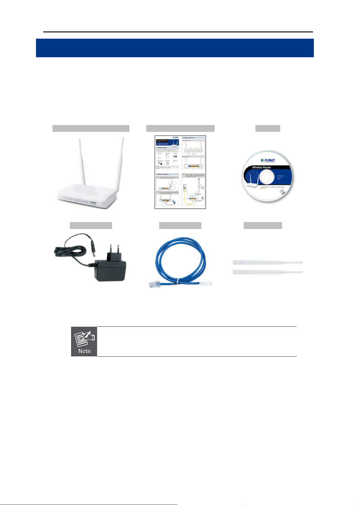
Thank you for choosing PLANET WNRT-633. Before installing the router, please verify the contents
inside the package box.
WNRT-633 Wireless Router Quick Installation Guide CD-ROM
(User Manual included)
Power Adapter Ethernet Cable 5dBi Antenna x 2
12V/1A DC output
100~240V AC input
If there is any item missing or damaged, please contact the seller
immediately.
RJ-45 / CAT5E 1 meter UTP
-1-
Page 9
User’s Manual of WNRT-633
1.2 Product Description
Multiple Wireless Network Technologies for Greater Access
Offering an instant network and flexibility for users to handle
network expansion and speed, the PLANET WNRT-633
Wireless Gigabit Router is the total solution for the Home,
Hotspot and the SOHO users. It offers 300Mbps wireless
speed, multiple operation modes Gigabit LAN and WAN
features to increase client mobility and speed within a
network. By installing the WNRT-633 as the central
connection point of network, the connected computers and
mobile devices are able to share the high speed broadband
Internet connection and networked server. With the four
built-in 10/100/1000Base-T LAN ports, it is easy to integrate
the wireless devices with existing wired network.
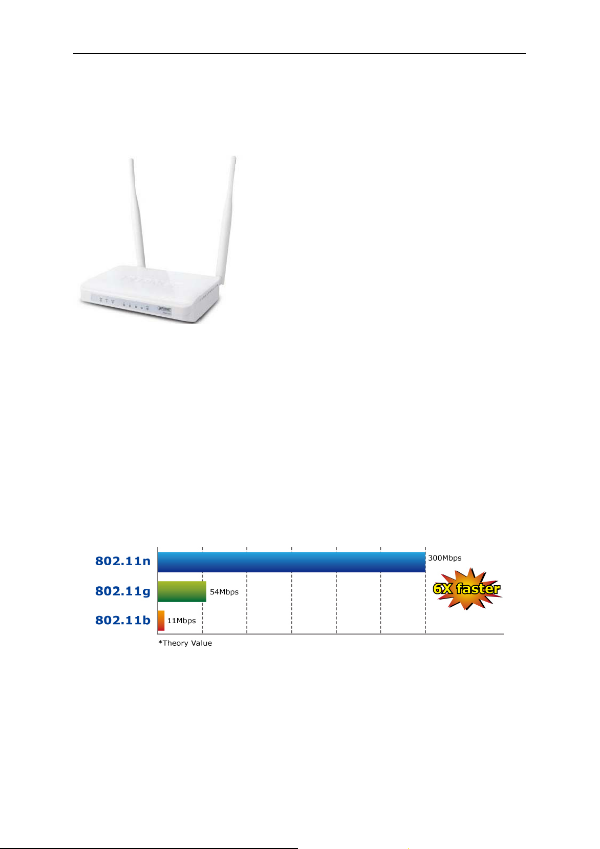
High Speed 802.11n Wireless
The WNRT-633 features latest IEEE 802.11n radio with 2T2R MIMO antenna technology to provide
improved wireless speed and coverage with up to 300Mbps upload and download data rate. The
incredible wireless speed makes it ideal for handling multiple HD movies stream, high resolution
on-line game, stereo music, VoIP and data streams at the same time stably and smoothly. It is also
backward compliant with 802.11g and 802.11b standards; thus, it is no need to change the existing
network for convenient maintenance. Just connect to the WNRT-633 and users can immediately enjoy
the high-speed wireless sharing.
Wireless Coverage Plus !
The WNRT-633 is equipped with 5dBi High-Gain antennas to provide strong signal and excellent
performance even in the long range or bad environment. With detachable RP-SMA connector design
in the WNRT-633, it allows users to manually exchange higher gain antenna for farther wireless
coverage range.
-2-
Page 10
User’s Manual of WNRT-633
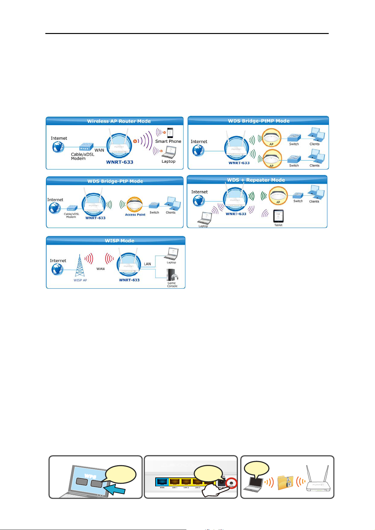
Easy Setup for Multiple Wireless Modes
The WNRT-633 supports multiple wireless modes including Gateway, Bridge, Repeater and WISP
(Wireless Internet Service Provider), for different network applications. Furthermore, with the built-in
Wizard Setup function, users can configure the WNRT-633 easily and quickly through a couple of
simple steps. It is so easy to apply the WNRT-633 to the existing wired network. The WNRT-633
definitely provides a total network solution for the home and the SOHO users.
Wide Range of Wireless Security Support
To secure the wireless communication, the WNRT-633 supports most up-to-date encryptions including
WPA/WPA2-PSK with TKIP/AES.
Made to fulfill enterprise and various applications demand, the
WNRT-633 enhances security and management features such as multiple SSID. It can create up to 5
virtual standalone APs with 5 different SSIDs according to individual security levels and encryption
scheme of various wireless devices.
One-touch Secure Wireless Connection
In order to simplify security settings for home and SOHO network, the WNRT-633 supports Wi-Fi
Protected Setup (WPS) with configuration in PBC and PIN type. Just push the WPS button or key in
the PIN code, the secure connection between the WNRT-633 and the wireless clients can be built
immediately,
which offers users a convenient and fast method to construct a secure wireless network.
WPS (Wi-Fi Protected Setup)
Quick & Easy Wireless Connection
STEP.1
WPS
Click
STEP.2
Connected
Press
-3-
STEP.3
WANWLAN 1234PWR WPS
WNRT-633
Page 11

User’s Manual of WNRT-633
Powerful Firewall and Complete Access Control Functions
The WNRT-633 supports NAT functions and allows multiple users to access Internet via only one
single legal IP. It provides Port Forwarding and DMZ for LAN PC to act as an application server.
Furthermore, the advanced firewall by the WNRT-633 can protect your Intranet clients from
unauthorized accesses and various DoS attacks from the Internet. In aspect of the firewall, the
WNRT-633 provides IP/MAC/URL filtering, and prevents possible hackers attack.
1.3 Product Features
IEEE Compliant Wireless LAN & Wired LAN
Compliant with IEEE 802.11n wireless technology capable up to 300Mbps data rate
Backward compatible with 802.11b/g standard
Equipped with all Gigabit RJ-45 ports (10/100/1000Mbps) of 1 WAN and 4 LAN ports
Auto MDI/MDI-X supported
Fixed-network Broadband Router
Supported Internet types: Dynamic IP/ Static IP/ PPPoE/ L2TP/ PPTP
Supports Static & Dynamic (RIP1 and 2) Routing
Supports IP / MAC-Based Bandwidth Control
Supports 802.1d STP & IGMP Proxy
Secure Network Connection
One-touch Wi-Fi Protected Setup (WPS)
Advanced security: 64-/128-bit WEP, WPA/WPA2 and WPA-PSK/WPA2-PSK (TKIP/AES
encryption) and 802.1x Authentication
Built-in NAT firewall features with Port/ IP/ MAC/ URL Filtering, and DoS protection
Supports Multiple-SSID to allow users to access different networks through a single AP
Advanced Networking function for Specific Application
Supports multiple sessions IPSec, L2TP, PPTP, and IPv6 VPN pass-through
Supports Port Forwarding, DMZ, UPnP and Dynamic DNS for various networking
applications
Supports DHCP Server
Easy Installation & Management
User Friendly Web-Based UI and setup Wizard for easy configuration
Remote Management allows configuration from a remote site
System status monitoring includes DHCP Client List and System Log
-4-
Page 12
1.4 Product Specifications
User’s Manual of WNRT-633
Product
Hardware Specifications
Interface
Antenna
WPS / Reset Button
LED Indicators PWR, WPS, WLAN, WAN/LAN with green light
Material Plastic
Dimensions
(W x D x H)
Weight 212g
Power Adapter
Wireless Interface Specifications
Standard Compliance with IEEE 802.11b/g/n
Frequency Band 2.4~2.4835GHz
Extend Frequency DSSS
Modulation Type DBPSK, DQPSK, QPSK, CCK and OFDM (BPSK/QPSK/16-QAM/ 64-QAM)
WNRT-633
300Mbps 802.11n Wireless Gigabit Router
WAN 1 x 10/100/1000Mbps Auto MDI/MDI-X RJ45 port
LAN 4 x 10/100/1000Mbps Auto MDI/MDI-X RJ45 ports
Wireless 2 x detachable RP-SMA Connectors
Gain: 2 x 5dBi antennas
Orientation: Omni-directional
Reset / WPS button at rear panel
Press for about 7 seconds to reset the device to factory default.
Press for 1 second to activate WPS function.
154 x 106 x 27 mm (without antenna)
154 x 136 x 27 mm (with antenna)
AC Input: 100~240V AC (50/60Hz)
DC Output: 12V, 1A
802.11n(40MHz):270/243/216/162/108/81/54/27Mbps
135/121.5/108/81/54/40.5/27/13.5Mbps (Dynamic)
Data Transmission
Rates
Transmission
Distance
Channel
Max. RF Power 20 dBm max. (EIRP)
Receive Sensitivity
Wireless Management Features
802.11n(20MHz):130/117/104/78/52/39/26/13Mbps
65/58.5/52/39/26/19.5/13/6.5Mbps (Dynamic)
802.11g:54/48/36/24/18/12/9/6Mbps (Dynamic)
802.11b:11/5.5/2/1Mbps (Dynamic)
Indoor up to 100m
outdoor up to 300m (it is limited to the environment)
America/ FCC: 2.412~2.462GHz (11 Channels)
Europe/ ETSI: 2.412~2.472GHz (13 Channels)
Japan/ TELEC: 2.412~2.484GHz (14 Channels)
270M: -68dBm@10% PER
130M: -68dBm@10% PER
54M: -68dBm@10% PER
11M: -85dBm@8% PER
Gateway(default)
Operation Mode
Bridge
WSP
Wireless Mode
AP
WDS
Repeater (WDS+AP)
Universal Repeater
(AP+Client)
-5-
Page 13
WEP (64/128-bit) encryption security
Encryption Security
WPA-Enterprise / WPA2-Enterprise (TKIP/AES)
WPA-Personal / WPA2-Personal (TKIP/AES)
802.1x Authentication
Provides wireless LAN ACL (Access Control List) filtering
Wireless Security
Wireless Advanced
Router Features
Internet Connection
Typ e
Wireless MAC address filtering
Supports WPS (Wi-Fi Protected Setup)
Enables/Disables SSID Broadcast
WMM(Wi-Fi Multimedia): 802.11e Wireless QoS
IAPP(Inter Access Point Protocol): 802.11f Wireless Roaming
Provides Wireless Statistics
Shares data and Internet access for users, supporting the following internet
accesses:
PPPoE
Dynamic IP
Static IP
PPTP
L2TP
NAT firewall with SPI (Stateful Packet Inspection)
Built-in NAT server supporting Port Forwarding, and DMZ
Firewall
Routing Protocol Static / Dynamic (RIP1 and 2) Routing
VPN Pass-through PPTP, L2TP, IPSec, IPv6
LAN
System Management
Standards Conformance
IEEE Standards
Other Protocols and
Standards
Environment
Temperature
Humidity
Built-in firewall with IP address/ MAC address/ Port/ URL filtering
Supports ICMP-FLOOD, UDP-FLOOD, TCP-SYN-FLOOD filter, DoS
protection
Built-in DHCP server supporting static IP address distributing
Supports UPnP, Dynamic DNS
Supports IGMP Proxy
Supports 802.1d STP (Spanning Tree)
IP / MAC-based Bandwidth Control
Web-based (HTTP) management interface
SNTP time synchronize
Easy firmware upgrade
System Log supports Remote Log
IEEE 802.11n (2T2R, up to 300Mbps)
IEEE 802.11g
IEEE 802.11b
IEEE 802.11i
IEEE 802.3 10Base-T
IEEE 802.3u 100Base-TX
IEEE 802.3x Flow Control
CSMA/CA, CSMA/CD, TCP/IP, DHCP, ICMP, NAT, PPPoE, SNTP
Operating: 0 ~ 40 degrees C
Storage: -40 ~ 70 degrees C
Operating: 10 ~ 90% (Non-Condensing)
Storage: 5 ~ 90% (Non-Condensing)
User’s Manual of WNRT-633
-6-
Page 14
User’s Manual of WNRT-633
Chapter 2. Hardware Installation
Please follow the instructions below to connect WNRT-633 to the existing network devices and your
computers.
2.1 Hardware Description
Dimensions: 154 x 136 x 27mm (W x D x H)
Weight : 212g
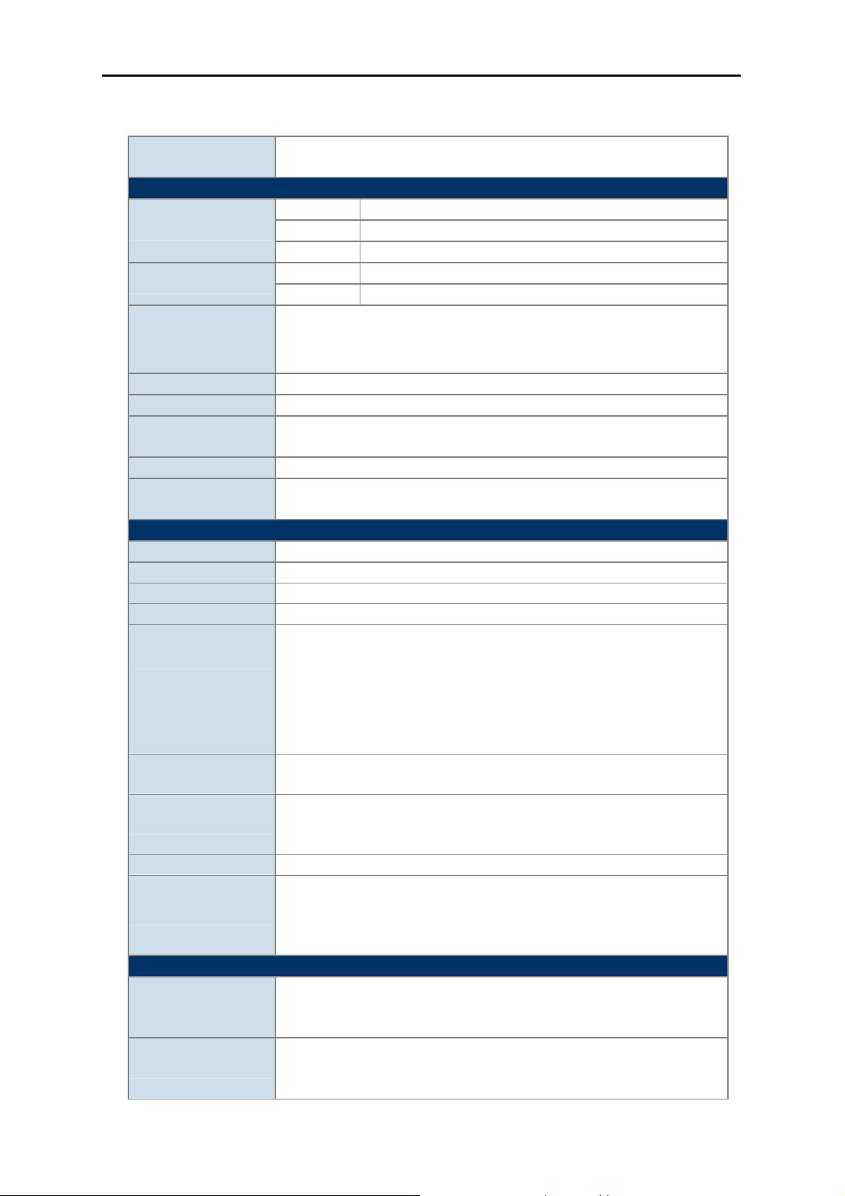
2.1.1 The Front Panel
The front panel provides a simple interface monitoring of the router. Figure 2-1 shows the front panel of
WNRT-633.
Front Panel
Figure 2-1 WNRT-633 Front Panel
-7-
Page 15

User’s Manual of WNRT-633
2.1.2 LED Indications
The LEDs on the top panel indicate the instant status of system power, wireless data activity, WPS,
and port links, and help monitor and troubleshoot when needed. Figure 2-2 and Table 2-1 show the
LED indications of the WNRT-633.
LED Definition
(Left to Right)
LED
PWR
WPS
WLAN
LAN
1~4
Figure 2-2 WNRT-633 LED Panel
STATUS FUNCTION
On Device power on
Flash The system is working properly
Off Device power off
The system is performing WPS authentication on a client
Flash
device.
On The 2.4G WiFi is activated
Flash Device is transmitting data wirelessly over 2.4GHz
On Link is established
Flash Packets are transmitting or receiving
Off LAN port is not connected
On Link is established
WAN
Flash Packets are transmitting or receiving
Off WAN port is not connected
Table 2-1 The LED indication
-8-
Page 16
User’s Manual of WNRT-633
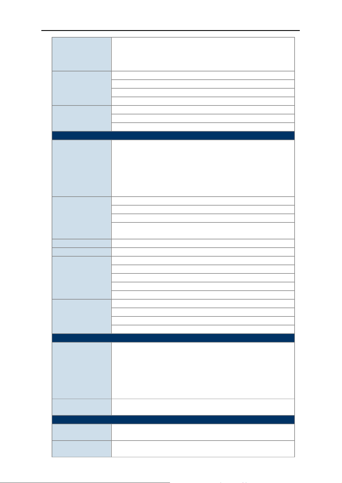
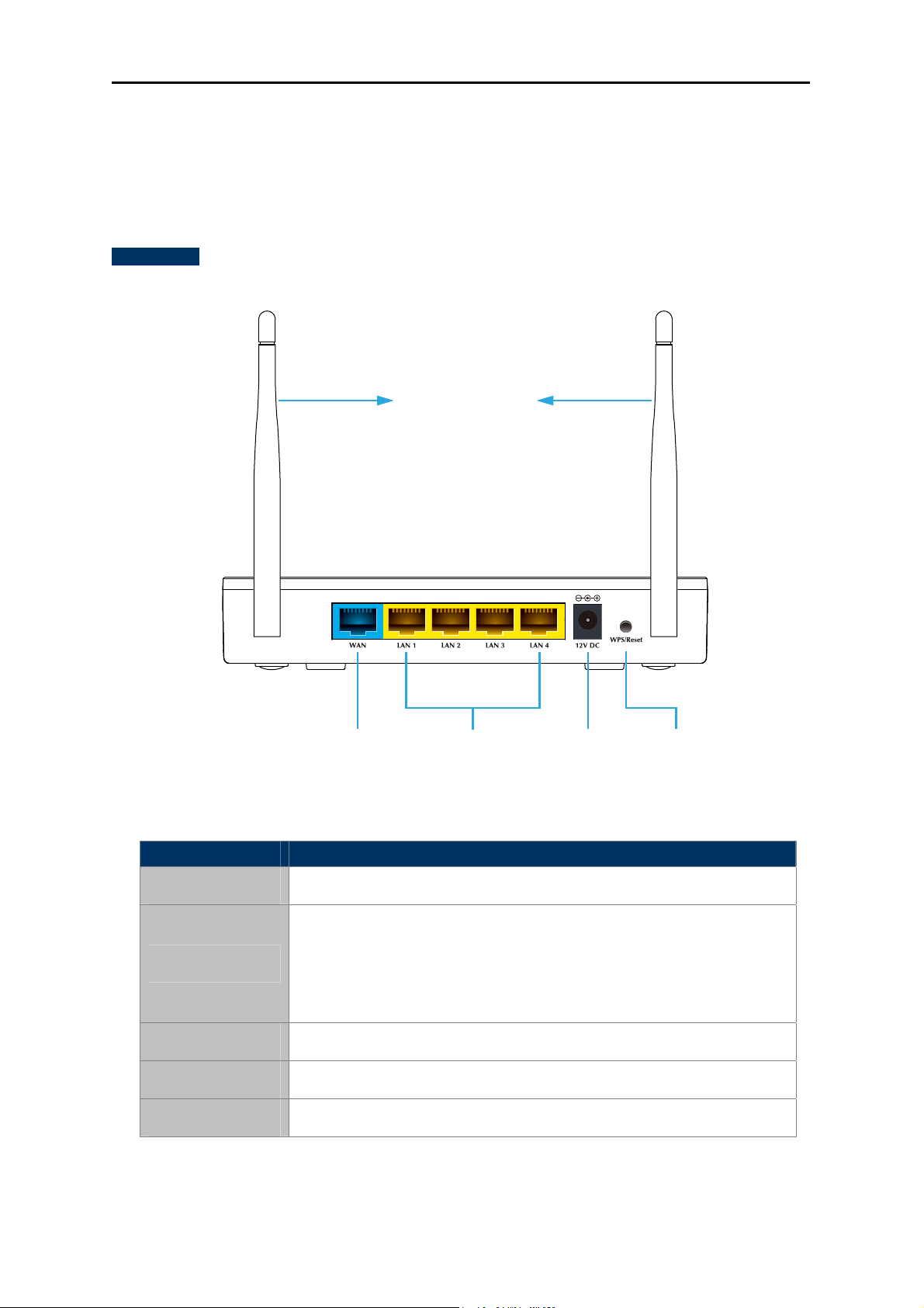
2.1.3 The Rear Panel
The rear panel provides the physical connectors connected to the power adapter and any other
network device. Figure 2-3 shows the rear panel of WNRT-633.
Rear Panel
5 dBi Antenna
Power WPS/Reset4 x Gigabit LAN PortsGigabit WAN Port
Figure 2-3 Rear Panel of WNRT-633
Interface Description
Antenna x 2 Fixed 5dBi Omni Dipole Antennas
Press the Reset button gently for 1 second and then release it.
The system starts to WPS connection.
WPS/Reset
Press the Reset button gently for 7 seconds and then release it.
The system restores to the factory default settings.
WAN Connect to the Cable/xDSL Modem, or the Ethernet
LAN1-4 Connect to the user’s PC or network devices
Power Connect to the power adapter provided in the package
Table 2-2 The Interface indication
-9-
Page 17
User’s Manual of WNRT-633
Chapter 3. Connecting to the Router
3.1 System Requirements
Broadband Internet Access Service (Cable/xDSL/Ethernet connection)
One Cable/xDSL Modem that has an RJ-45 connector (not necessary if the Router is
connected directly to the Ethernet.)
PCs with a working Ethernet Adapter and an Ethernet cable with RJ-45 connectors
PC of subscribers running Windows 98/ME, NT4.0, 2000/XP, Windows Vista / Win 7, MAC
OS 9 or later, Linux, UNIX or other platform compatible with TCP/IP protocols
The above PC installed with WEB Browser
1. The Router in the following instructions is named as PLANET WNRT-633.
2. It is recommended to use Internet Explore 7.0 or above to access the Router.
3.2 Installing the Router
Before installing the Router, make sure your PC is connected to the Internet through the broadband
service successfully at this moment. If there is any problem, please contact your local ISP. After that,
please install the Router according to the following steps. Don't forget to pull out the power plug and
keep your hands dry.
Step 1. Power off your PC, Cable/xDSL Modem, and the Wireless Router.
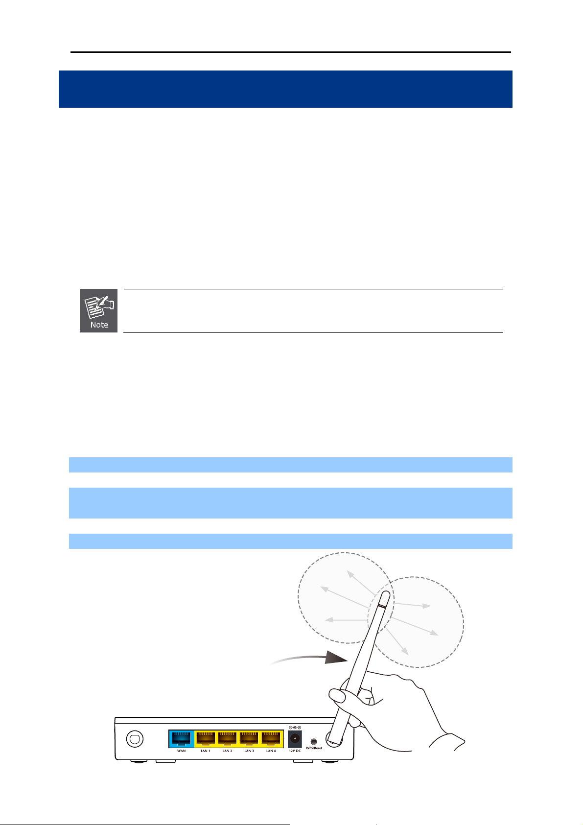
Step 2. Locate an optimum location for the Wireless Router. The best place is usually at the center of
your wireless network.
Step 3. Adjust the direction of the antenna. Normally, upright is a good direction.
Figure 3-1 Adjust the direction of the antenna
-10-
Page 18
User’s Manual of WNRT-633
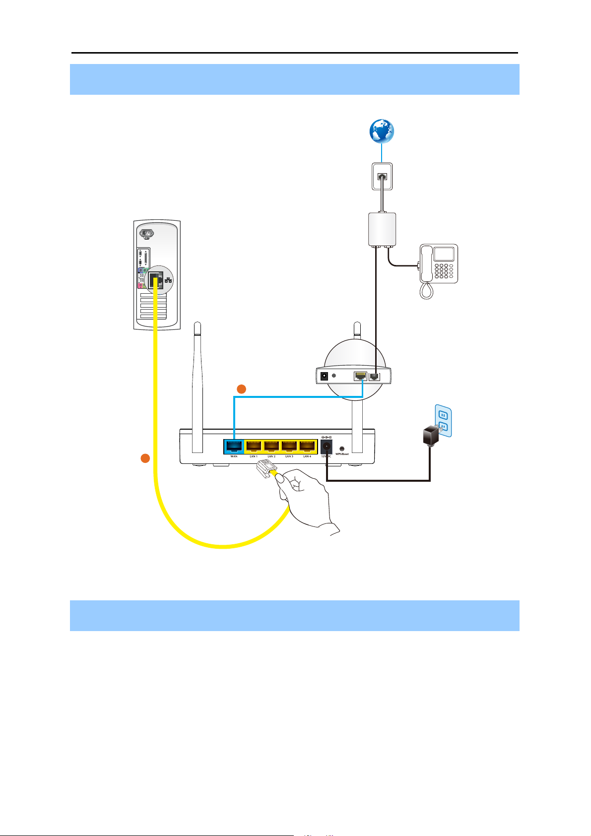
Step 4. Connect the PC or Switch/Hub in your LAN to the LAN Ports (Yellow ports) of the Router with
Ethernet cable as shown in Figure 3-2.
Internet
Line
Splitter
ADSL Phone
Telephone Wire
Phone
PC
Cable
2
Ethernet Cable
Modem
WNRT-633
1
Power
Ethernet Cable
Power
Adapter
Figure 3-2 Hardware Installation of the WNRT-633 Wireless Router
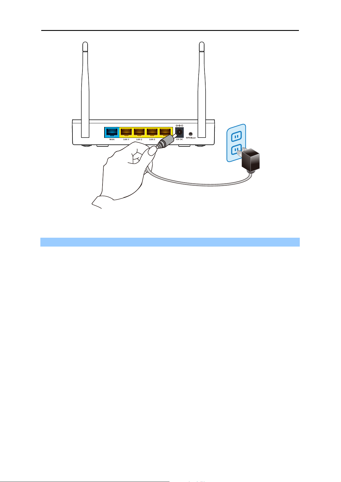
Step 5. Connect the power adapter to the power socket on the Wireless Router, and the other end
into an electrical outlet. Then power on the Wireless Router.
-11-
Page 19
User’s Manual of WNRT-633
Power
Figure 3-3 Power on the Wireless Router
Step 6. Power on your PC and Cable/xDSL Modem.
-12-
Page 20

User’s Manual of WNRT-633
Chapter 4. Installation Guide
This chapter will show you how to configure the basic functions of your Wireless Router using Quick
Setup within minutes.
A computer with wired Ethernet connection to the Wireless Router is required for the
first-time configuration.
4.1 Manual Network Setup - TCP/IP Configuration
The default IP address of the WNRT-633 is 192.168.1.1, and the default Subnet Mask is
255.255.255.0. These values can be changed as you desire in the web UI of the WNRT-633. In this
section, we use all the default values for description.
Whether the WNRT-633 is configured via wired or wireless connection, the PC needs to be assigned
an IP address first. Before you connect the local PC to the WNRT-633 via wired or wireless connection,
please configure the IP address for your PC in the following two ways first.
Obtain an IP address automatically
Configure the IP address manually
In the following sections, we’ll introduce how to install and configure the TCP/IP correctly in Windows
7. And the procedures in other operating systems are similar. First, make sure your Ethernet Adapter is
working, and refer to the Ethernet adapter’s manual if needed.
4.1.1 Obtain an IP Address Automatically
Summary:
1. Set up the TCP/IP Protocol in "Obtain an IP address automatically" mode on your PC.
2. Then the WNRT-633 built-in DHCP server will assign IP address to the PC automatically.
If you are sure the DHCP server of WNRT-633 is enabled (the default setting of Router Mode), you can
set up the TCP/IP Protocol in "Obtain an IP address automatically" mode on your PC. And then the
WNRT-633 built-in DHCP server will assign an IP address to the PC automatically.
1. Install TCP/IP component
1) On the Windows taskbar, click the Start button, point to Control Panel, and then click it.
2) Under the Network and Internet icon, click on the View network status and tasks. And then
-13-
Page 21

click Change adapter settings.
User’s Manual of WNRT-633
Figure 4-1-1 Change adapter settings
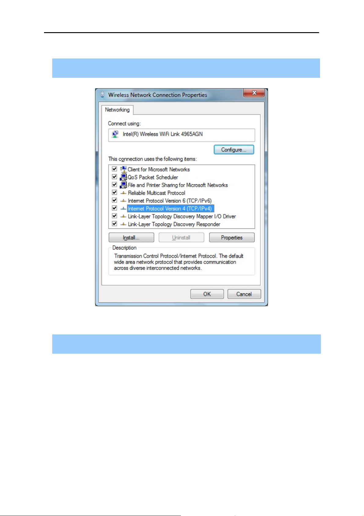
3) Right-click on the Wireless Network Connection, and select Properties in the appearing
window.
-14-
Page 22
User’s Manual of WNRT-633
Figure 4-1-2 Network Connection Properties
4) In the prompt window shown below, double click on the Internet Protocol Version 4
(TCP/IPv4).
Figure 4-1-3 TCP/IP Setting
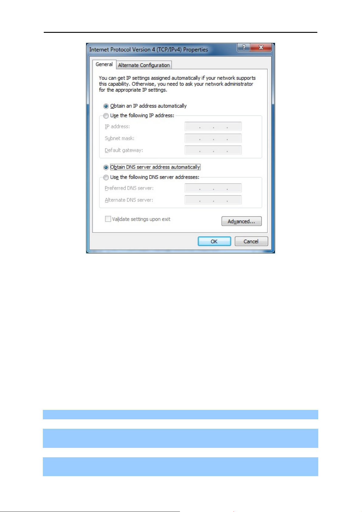
5) Choose Obtain an IP address automatically, and Obtain DNS server address automatically
as shown in the figure below. Then click OK to save your settings.
-15-
Page 23
User’s Manual of WNRT-633
Figure 4-1-4 Obtain an IP address automatically
4.1.2 Configure the IP address manually
Summary:
Set up the TCP/IP Protocol for your PC.
Configure the network parameters. The IP address is 192.168.1.xxx ("xxx" is any number
from 2 to 254), Subnet Mask is 255.255.255.0, and Gateway is 192.168.1.1 (The Router's
default IP address)
If you are sure the DHCP server of WNRT-633 is disabled (the default setting of AP Mode and Client
Mode), you can configure the IP address manually. The IP address of your PC should be
192.168.1.xxx (the same subnet of the IP address of WNRT-633, and "xxx" is any number from 2 to
254), Subnet Mask is 255.255.255.0, and the Gateway is 192.168.1.1 (The default IP address of
WNRT-633)
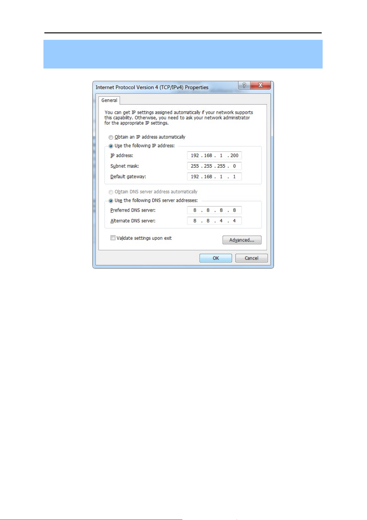
1) Continue the settings from the last figure, select Use the following IP address radio button.
2) If the LAN IP address of the WNRT-633 is 192.168.1.1, enter IP address 192.168.1.x (x is from 2
to 254), and Subnet mask 255.255.255.0.
3) Enter the LAN IP address of the WNRT-633 (the default IP is 192.168.1.1) into the Default
gateway field.
-16-
Page 24
User’s Manual of WNRT-633
4) Select Use the following DNS server addresses radio button. In the Preferred DNS Server field,
you can enter the DNS server IP address provided by your local ISP. Then click OK to save your
settings.
Figure 4-1-5
Now, you can run the Ping command in the command prompt to verify the network connection
between your PC and the Router. The following example is in Windows 7 OS. Please follow the steps
below:
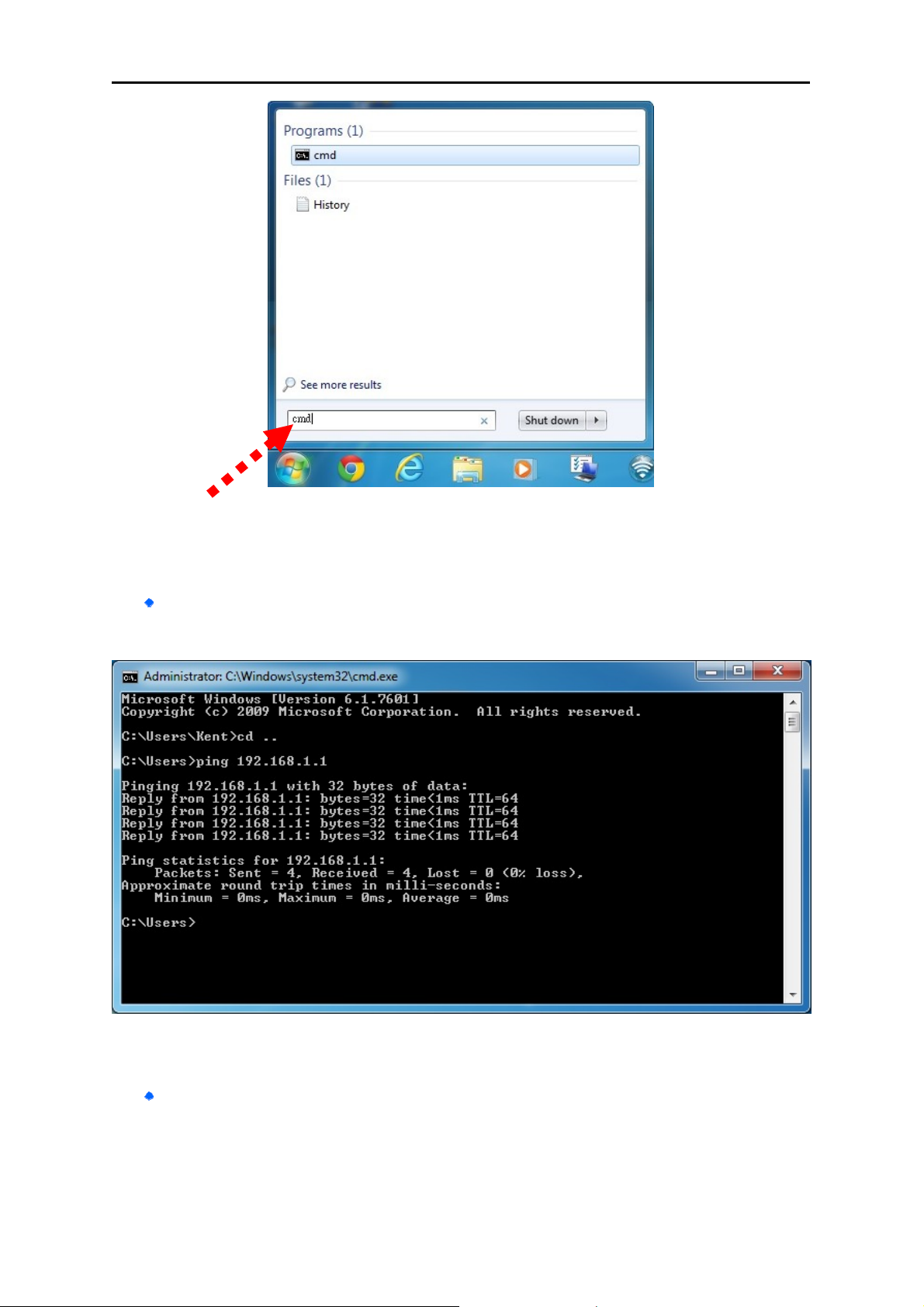
1. Click on Start
2. Type “cmd” in the Search box.
-17-
Page 25
User’s Manual of WNRT-633
Figure 4-1-6
3. Open a command prompt, and type ping 192.168.1.1, and then press Enter.
If the result displayed is similar to Figure 4-1-7, it means the connection between your PC
and the Router has been established well.
Figure 4-1-7 Success result of Ping command
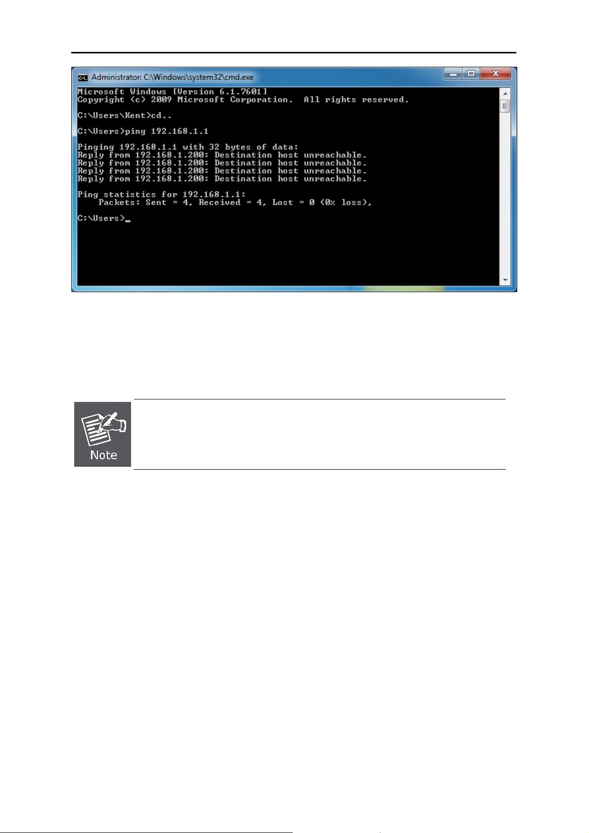
If the result displayed is similar to Figure 4-1-8, it means the connection between your PC
and the Router has failed.
-18-
Page 26
User’s Manual of WNRT-633
Figure 4-1-8 Failure result of Ping command
If the address is 0.0.0.0, check your adapter installation, security settings, and the settings on your
router. Some firewall software programs may block a DHCP request on newly installed adapters.
1. The 1/2/3/4 LEDs of LAN ports which you link to on the Router and LEDs on your
PC's adapter should be lit.
2. If the Router's IP address is 192.168.1.1, your PC's IP address must be within the
range of 192.168.1.2 ~ 192.168.1.254.
-19-
Page 27
User’s Manual of WNRT-633
4.2 Starting Setup in Web UI
It is easy to configure and manage the WNRT-633 via web browser.
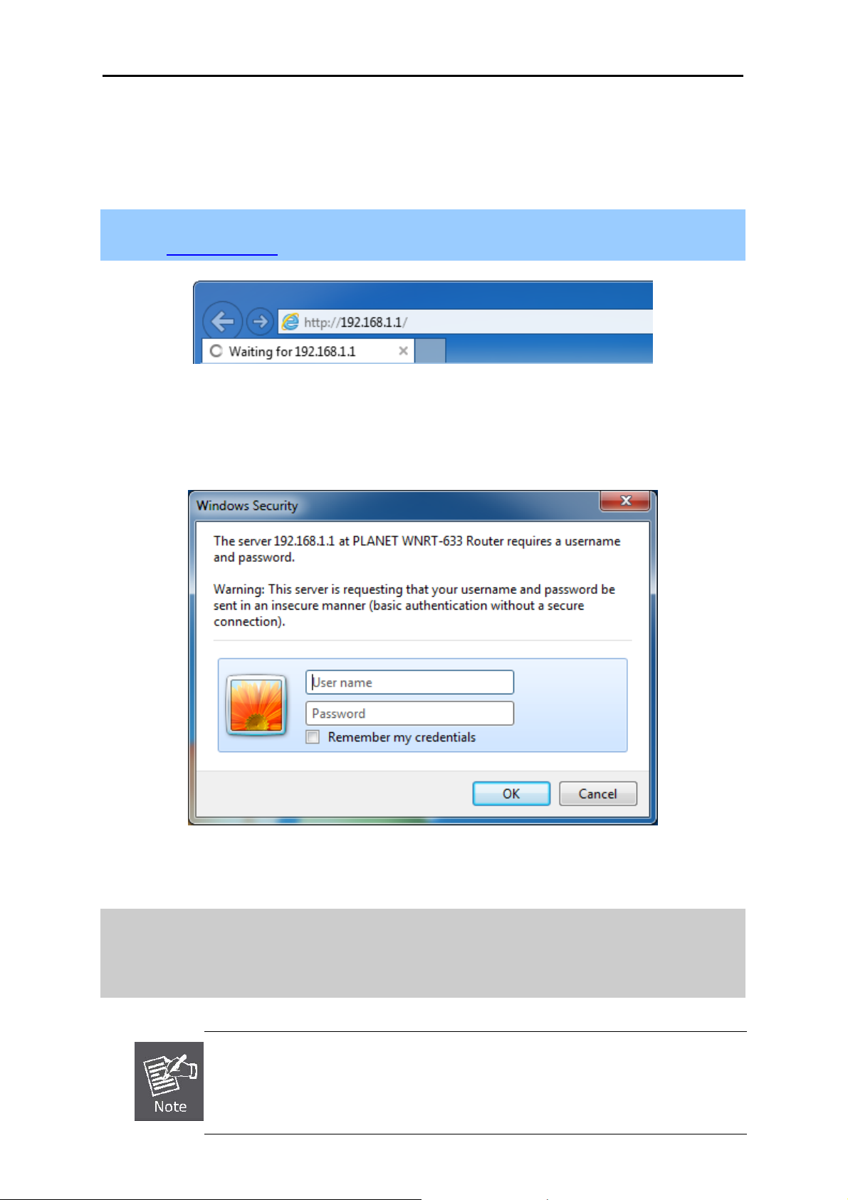
Step 1. To access the configuration utility, open a web-browser and enter the default IP address
http://192.168.1.1 in the web address field of the browser.
Figure 4-2-1 Login the Router
After a moment, a login window will appear. Enter the User Name and Password. Then click the OK
button or press the Enter key.
Default IP Address: 192.168.1.1
Default User name: admin
Default Password: admin
If the above screen does not pop up, it may mean that your web-browser has been set
to a proxy. Go to your web browser’s Tools menu>Internet
Options>Connections>LAN Settings, in the screen that appears, cancel the Using
Proxy checkbox, and click OK to finish it.
Figure 4-2-2 Login Window
-20-
Page 28
User’s Manual of WNRT-633
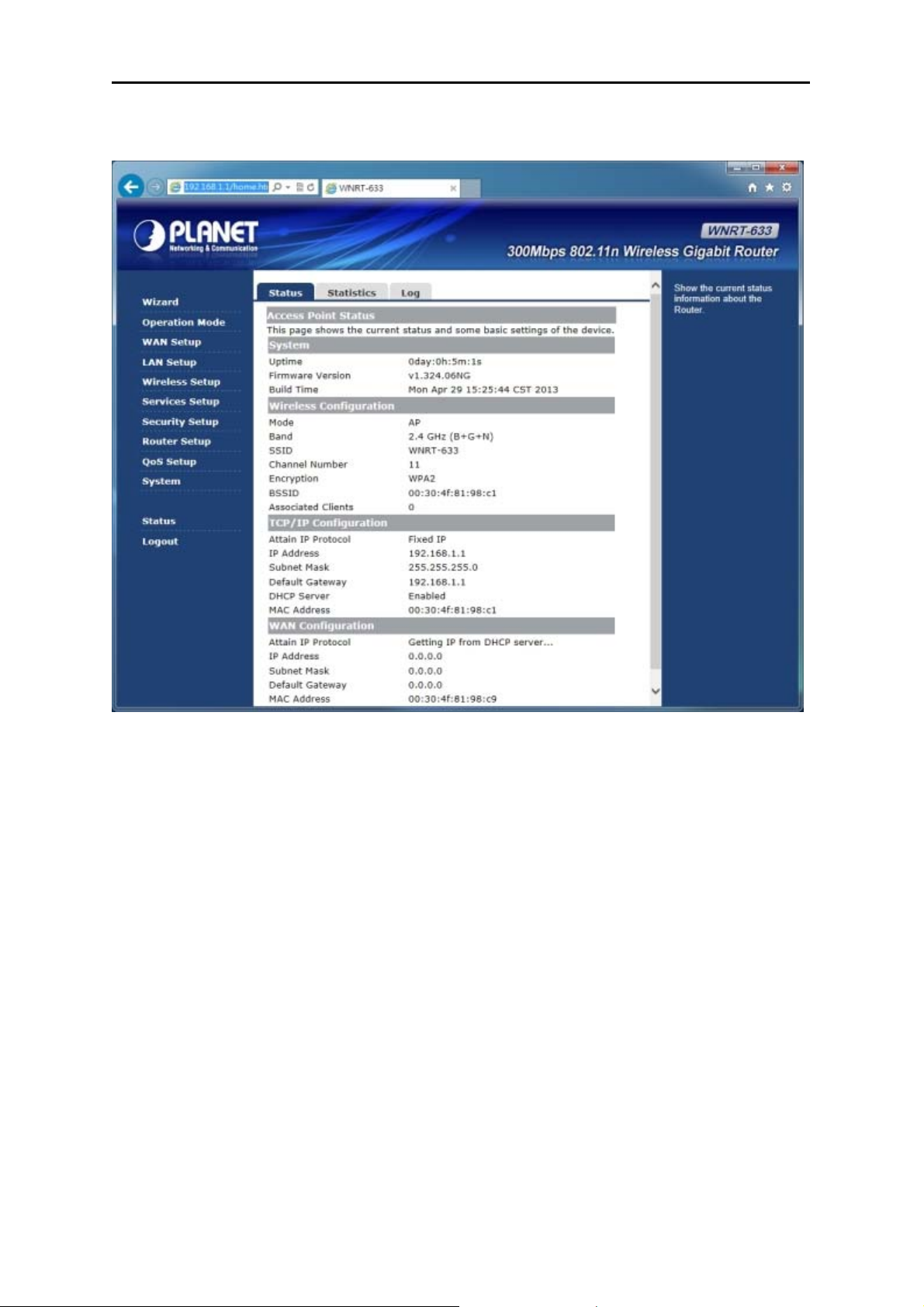
After you enter the username and password, the main screen appears as in Figure 4-2-3
Figure 4-2-3 WNRT-633 Web UI Screenshot
On this page, you can view information about the current running status of WNRT-633, including WAN
interface, LAN interface, wireless interface settings and status, and firmware version information.
The next chapter will introduce the functions of the web UI.
-21-
Page 29
User’s Manual of WNRT-633
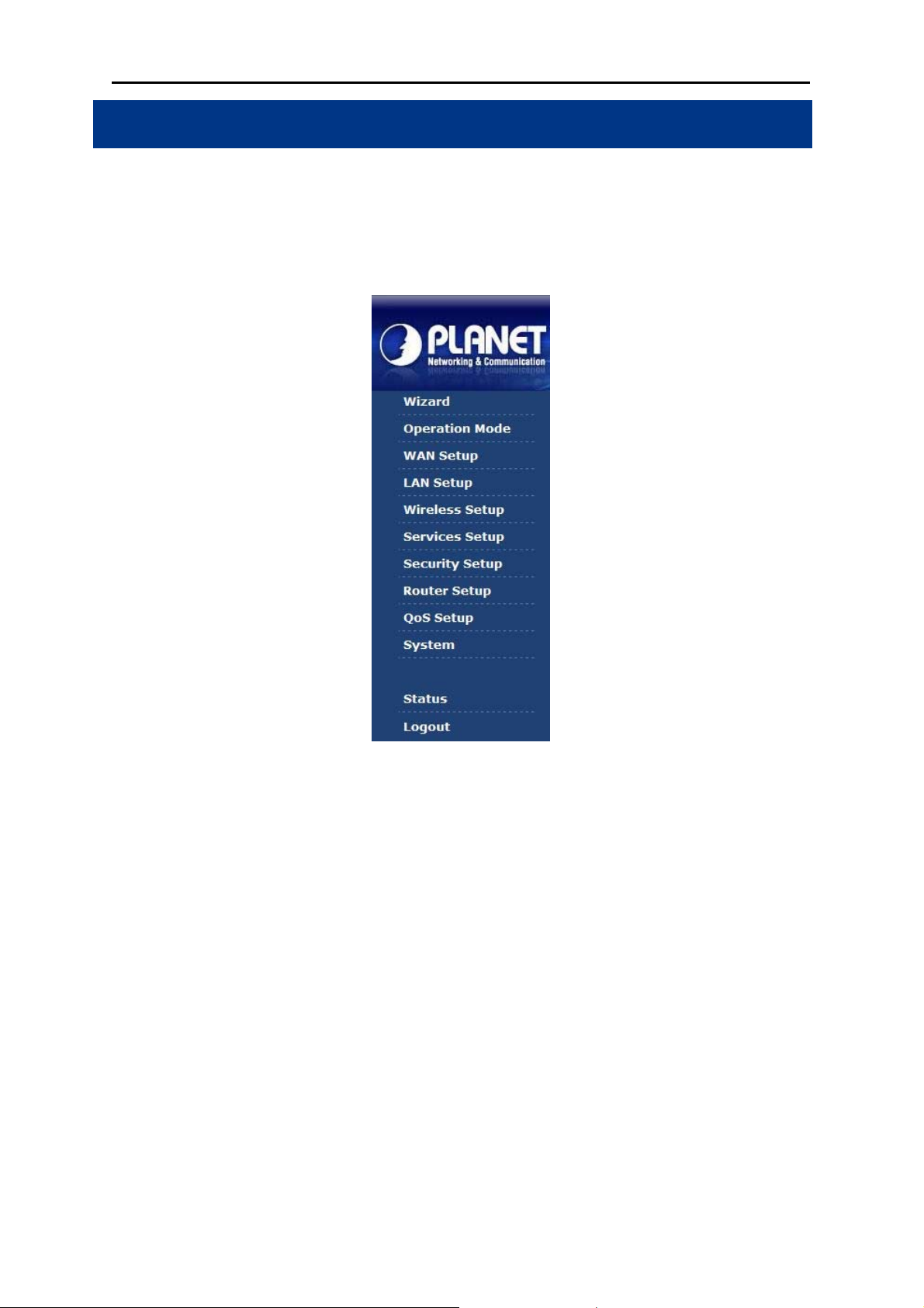
Chapter 5. Configuration in Web UI
After successfully logging into the web UI of the WNRT-633, you will see the main menus on the left
side of the web-based utility. There are some different options appearing as the operation mode
changes. For example, the figure below is the menu of Router Mode in the web UI.
During operation, if you are not clear about a certain feature, there are the corresponding explanations
and instructions on the right side of the web page; you can simply read all related helpful info.
The details of the functions in each operation mode are listed in the following sections.
5.1 Wizard
The Setup Wizard will guide the user to configure the WNRT-633 easily and quickly. There are
different procedures in different operation modes. According to the operation mode you switch to,
please follow the instructions below to configure the WNRT-633 via Setup Wizard.
-22-
Page 30

User’s Manual of WNRT-633
Figure 5-1-1 The Setup Wizard steps screenshot
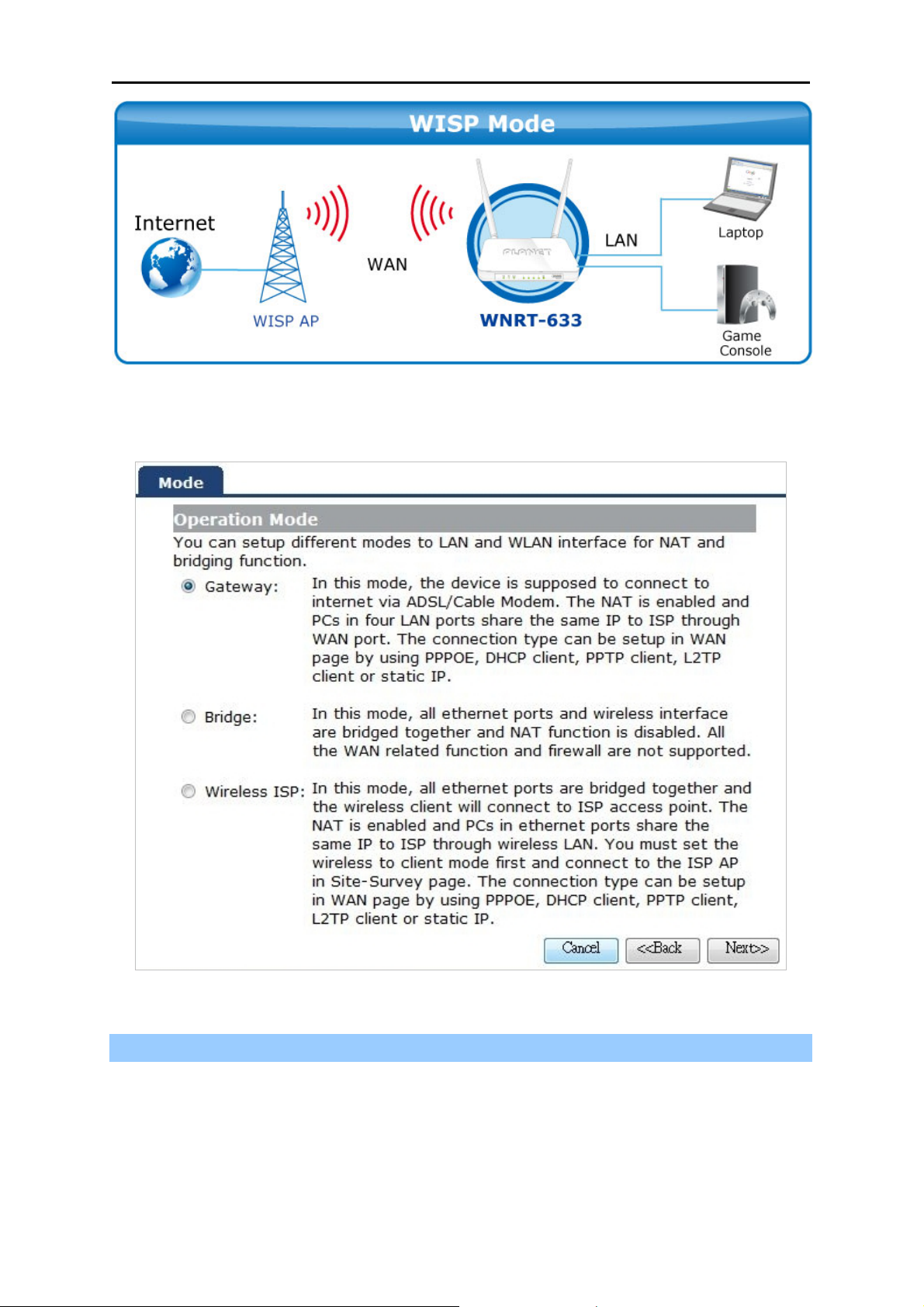
Step 1: Setup Operation Mode
The router supports three operation modes, Gateway, Bridge and Wireless ISP.
-23-
Page 31
User’s Manual of WNRT-633
Each mode is suitable for different uses. Please choose the correct mode.
Figure 5-1-2 Setup Wizard – Operation Mode screenshot
Step 2: Time Zone Setting
The Time Configuration option allows you to configure, update, and maintain the correct time on the
internal system clock. Daylight Saving can also be configured to automatically adjust the time when
needed.
-24-
Page 32
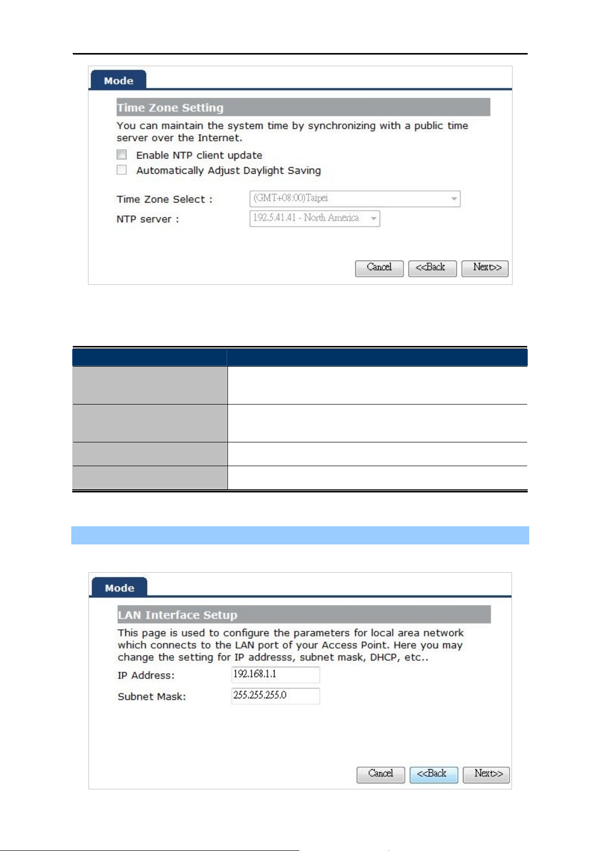
Figure 5-1-3 Setup Wizard – Time Zone Setting screenshot
The page includes the following fields:
User’s Manual of WNRT-633
Object Description
Enable NTP client update
Check this box to connect NTP Server and synchronize internet
time.
Automatically Adjust
Daylight Saving
Time Zone Select
NTP Server
Check this box, system will adjust the daylight saving
automatically.
Select the Time Zone from the drop-down menu.
Select the NTP Server from the drop-down menu.
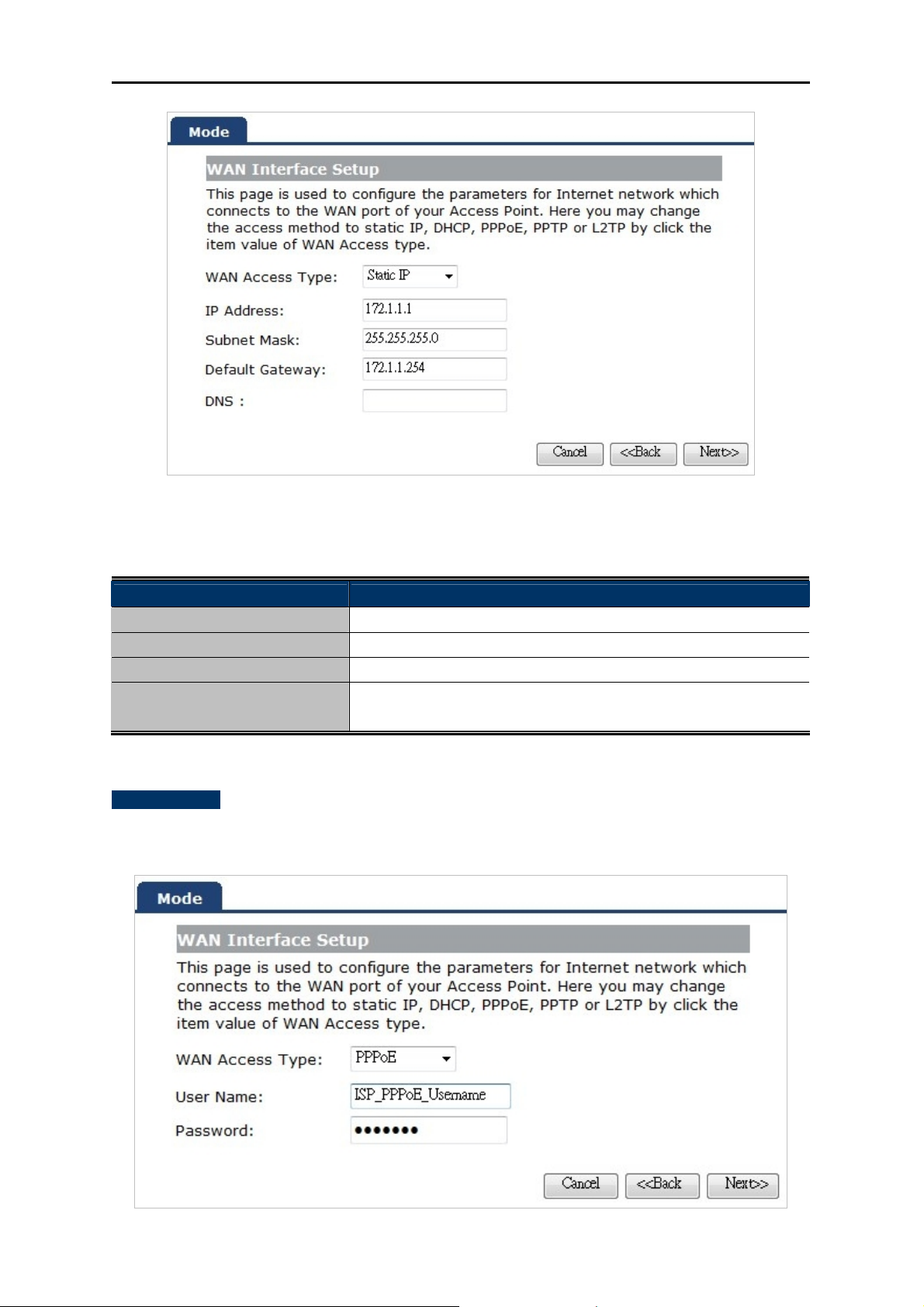
Step 3: LAN Interface Setting
Set up the IP Address and Subnet Mask for the LAN interface.
Figure 5-1-4 Setup Wizard – LAN Interface Setup screenshot
-25-
Page 33

User’s Manual of WNRT-633
The page includes the following fields:
Object Description
IP Address
Enter the IP address of your Router.
Factory default: 192.168.1.1
Subnet Mask
An address code that determines the size of the network.
Normally use 255.255.255.0 as the subnet mask.
Step 4 WAN Interface Setting
The Wireless Router supports five access modes in the WAN side. Please choose the correct mode
according to your ISP Service.
Mode 1 - DHCP Client
Figure 5-1-5 Setup Wizard – WAN Interface Setup screenshot
Select DHCP Client to obtain IP Address information automatically from your ISP.
Mode 2 Static IP
Select Static IP Address if all the Internet port’s IP information is provided to you by your ISP. You will
need to enter the IP address, subnet mask, gateway address, and DNS address provided to you by
your ISP. Each IP address entered in the fields must be in the appropriate IP form, which are four
octets separated by a dot (x.x.x.x). The Router will not accept the IP address if it is not in this format.
-26-
Page 34
User’s Manual of WNRT-633
Figure 5-1-6 WAN Interface Setup – Static IP setup screenshot
The page includes the following fields:
Object Description
IP Address
Subnet Mask
Default Gateway
DNS
Enter the IP address assigned by your ISP.
Enter the Subnet Mask assigned by your ISP.
Enter the Gateway assigned by your ISP.
The DNS server information will be supplied by your ISP
(Internet Service Provider).
Mode 3 PPPoE
Choose PPPoE (Point to Point Protocol over Ethernet) if your ISP uses a PPPoE connection. Your
ISP will provide you with a username and password. This option is typically used for DSL services.
Figure 5-1-7 WAN Interface Setup – PPPoE setup screenshot
-27-
Page 35
The page includes the following fields:
Object Description
User Name
Enter your PPPoE user name.
User’s Manual of WNRT-633
Password
Enter your PPPoE password.
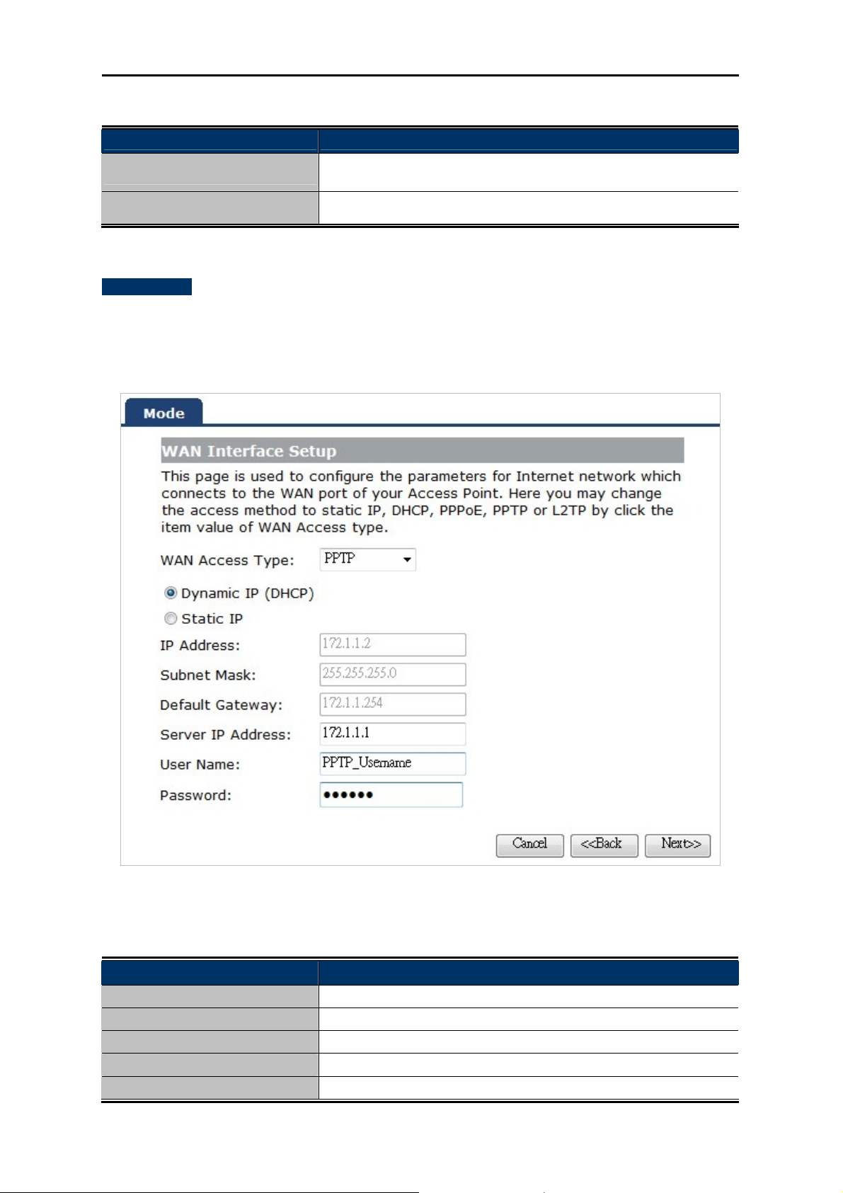
Mode 4 PPTP
Choose PPTP (Point-to-Point-Tunneling Protocol) if your ISP uses a PPTP connection. Your ISP
will provide you with IP information and PPTP Server IP Address; of course, it also includes a
username and password. This mode is typically used for DSL services.
Figure 5-1-8 WAN Interface Setup – PPTP setup screenshot
The page includes the following fields:
Object Description
IP Address
Subnet Mask
Server IP Address
User Name
Password
Enter the IP address.
Enter the subnet Mask.
Enter the PPTP Server IP address provided by your ISP.
Enter your PPTP username.
Enter your PPTP password.
-28-
Page 36

User’s Manual of WNRT-633
Mode 5 L2TP
Choose L2TP (Layer 2 Tunneling Protocol) if your ISP uses a L2TP connection. Your ISP will provide
you with a username and password.
Figure 5-1-9 WAN Interface Setup – L2TP setup screenshot
The page includes the following fields:
Object Description
IP Address Enter the IP address.
Subnet Mask Enter the subnet Mask.
Server IP Address Enter the L2TP Server IP address provided by your ISP.
User Name Enter your L2TP username.
Password Enter your L2TP password.
-29-
Page 37

Step 5: WLAN Settings
User’s Manual of WNRT-633
Figure 5-1-10 Wireless Basic Settings screenshot
The page includes the following fields:
Object Description
Band
Supports 802.11B, 802.11G, 802.11N and mixed. Please choose
its band according to your clients.
Mode
Network Type
SSID
Channel Width
Supports AP, Client, WDS and AP+WDS mode.
This type is only valid in client mode.
Service Set Identifier, it identifies your wireless network.
Select 40MHz if you use 802.11n or 802.11n mixed mode,
otherwise 20MHz, it is default value.
Control Sideband:
Channel Number
Enable Mac Clone
It is only valid when you choose channel width 40MHz.
Indicates the channel setting for the router.
Enables or disables MAC clone option.
You can use the "Mac Clone" button to copy the MAC address of
the Ethernet Card installed by your ISP and replace the WAN
MAC address with this MAC address.
-30-
Page 38
User’s Manual of WNRT-633
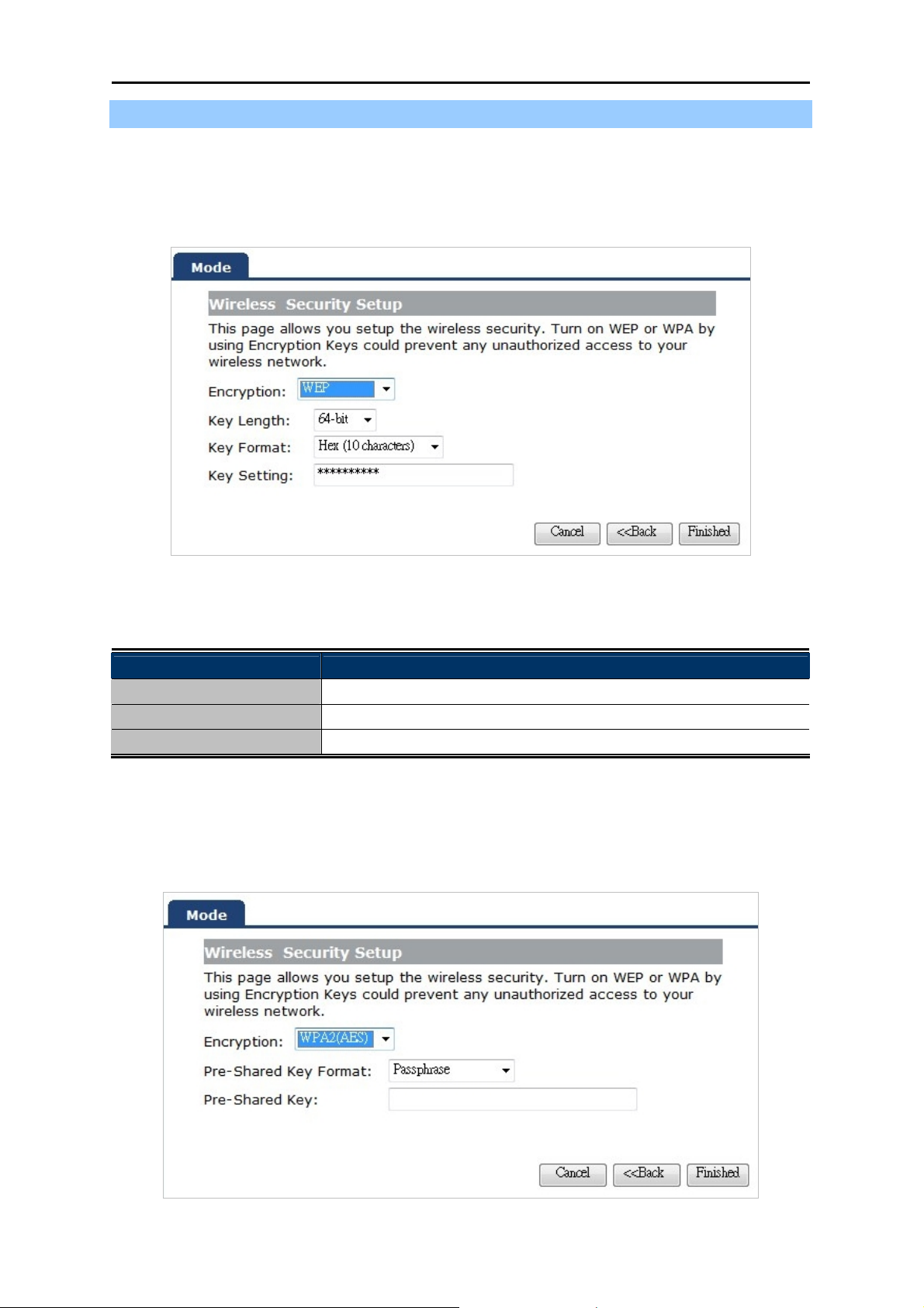
Step 6: Wireless Security Setup
Secure your wireless network by turning on the WPA or WEP security feature on the router. For this
section you can set WEP and WPA-PSK security mode.
Encryption: WEP
The following picture shows how to set the WEP security.
Figure 5-1-11 Wireless Security Setup – WEP setting screenshot
The page includes the following fields:
Object Description
Key length
Key Format
Key Setting
WEP supports 64-bit or 128-bit security key.
User can enter key in ASCII or Hex format.
Enter the key, its format is limited by the Key format, ASCII or Hex.
Encryption: WPA-PSK
The following picture shows how to set WPA-PSK security. You can select WPA (TKIP), WPA2 (AES)
and Mixed mode.
Figure 5-1-12 Wireless Security Setup – WPA setting screenshot
-31-
Page 39
The page includes the following fields:
Object Description
Pre-Shared Key Format
Specify the format of the key, pass phrase or hex.
User’s Manual of WNRT-633
Pre-Shared Key
Enter the key here, its format is limited by the key format.
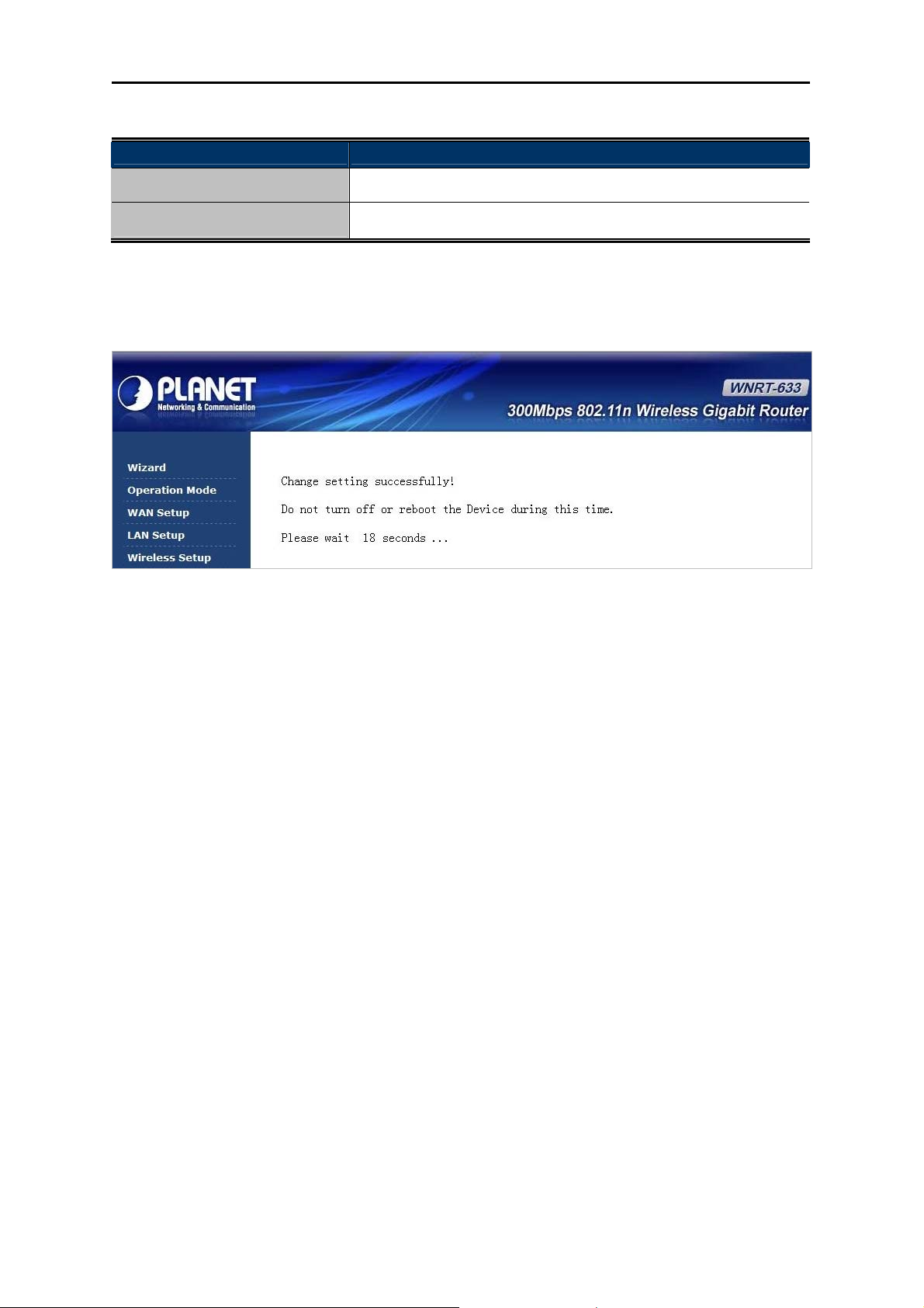
Click the Reboot button to make your wireless configuration to take effect and finish the Setup
Wizard.
Figure 5-1-13
After the rebooting, please check whether you can access the Internet or not in the “Status” page.
-32-
Page 40

User’s Manual of WNRT-633
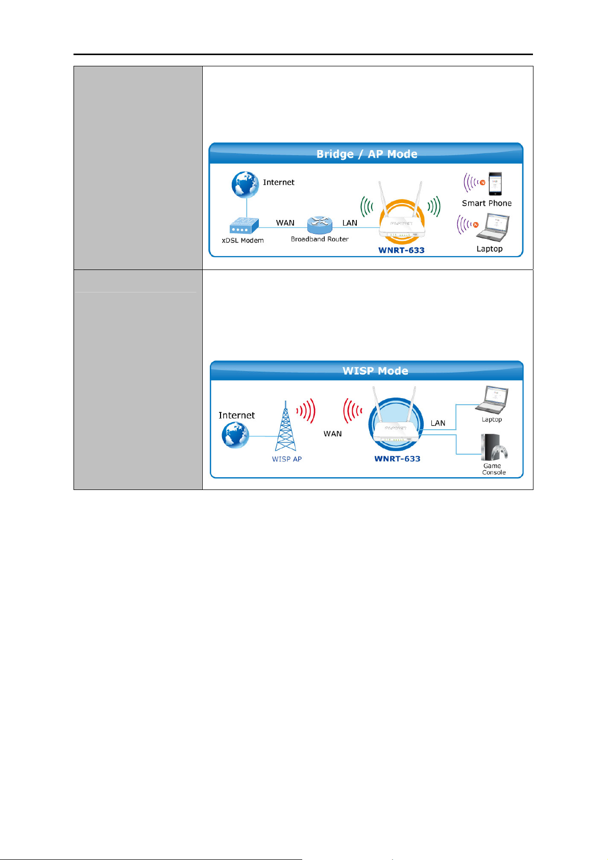
5.2 Operation Mode
This page shows the current operation mode, and users can set different modes to LAN and WLAN
interface for NAT and bridging function on the WNRT-633.
Figure 5-2-1 Operation Mode
The page includes the following fields:
Object Description
Gateway
In this mode, the device enables multiusers to share Internet via
ADSL/Cable Modem. The wireless port shares the same IP to ISP
through Ethernet WAN port. The Wireless port acts the same as a LAN
port while at AP Router mode.
-33-
Page 41
User’s Manual of WNRT-633
Bridge
Wireless ISP
In this mode, the device can be used to combine multiple local
networks together to the same one via wireless connections, especially
for a home or office where separated networks can't be connected
easily together with a cable.
In this mode, the device enables multiusers to share Internet from
WISP. The LAN port devices share the same IP from WISP through
Wireless port. While connecting to WISP, the Wireless port works as
a WAN port at AP Client Router mode. The Ethernet port acts as a
LAN port.
5.3 WAN Setup
You can configure WAN connection type manually here just like it in Setup Wizard, and set advanced
functions like DDNS (Dynamic DNS) here.
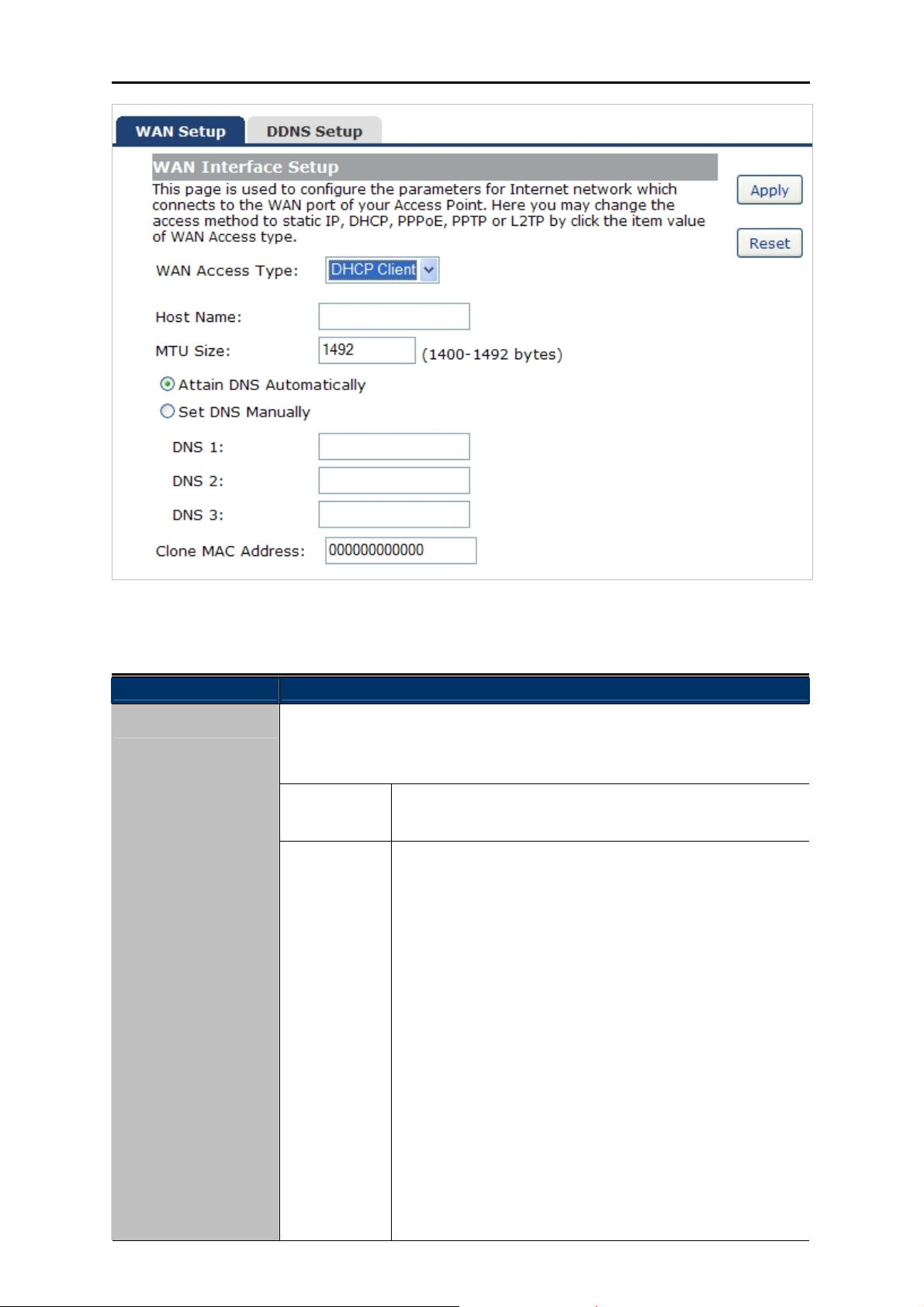
5.3.1 WAN Interface
This page is used to configure the parameters for Internet network which connects to the WAN port of
your Wireless Router. Here you may change the access method to static IP, DHCP, PPPoE, PPTP or
L2TP by clicking the item value of the WAN Access type.
Choose menu “WAN Setup WAN Setup”, and you can configure the parameters for the Internet
network. After the configuration, please click the “Apply” button to save the settings.
-34-
Page 42
User’s Manual of WNRT-633
Figure 5-3-1 WAN Interface Setup screenshot
The page includes the following fields:
Object Description
WAN Access Type
Please select the corresponding WAN Access Type for the Internet, and fill
the correct parameters from your local ISP in the fields which appear
below.
DHCP Client
Static IP
Select DHCP Client to obtain IP Address information
automatically from your ISP.
Select Static IP Address if all the Internet port’s IP
information is provided to you by your ISP (Internet Service
Provider). You will need to enter the IP address, subnet
mask, gateway address, and DNS address provided to you
by your ISP.
Each IP address entered in the fields must be in the
appropriate IP form, which are four octets separated by a dot
(x.x.x.x). The Router will not accept the IP address if it is not
in this format.
IP Address
Enter the IP address assigned by your ISP.
Subnet Mask
Enter the Subnet Mask assigned by your ISP.
Default Gateway
Enter the Gateway assigned by your ISP.
-35-
Page 43

PPPoE
PPTP
User’s Manual of WNRT-633
DNS
The DNS server information will be supplied by your ISP.
Choose PPPoE (Point to Point Protocol over Ethernet) if
your ISP uses a PPPoE connection. Your ISP will provide
you with a username and password. This option is typically
used for DSL services.
User Name
Enter your PPPoE user name.
Password
Enter your PPPoE password.
Choose PPTP (Point-to-Point-Tunneling Protocol) if your ISP
uses a PPTP connection. Your ISP will provide you with IP
information and PPTP Server IP Address; of course, it also
includes a username and password. This mode is typically
used for DSL services.
L2TP
IP Address
Enter the IP address..
Subnet Mask
Enter the Subnet Mask.
Server IP Address
Enter the PPTP Server IP address provided by your ISP.
User Name
Enter your PPTP user name.
Password
Enter your PPTP password.
Choose L2TP (Layer 2 Tunneling Protocol) if your ISP uses
a L2TP connection. Your ISP will provide you with a
username and password.
IP Address
Enter the IP address..
Subnet Mask
Enter the Subnet Mask.
Host Name
Server IP Address
Enter the L2TP Server IP address provided by your ISP.
User Name
Enter your L2TP user name.
Password
Enter your L2TP password.
This option specifies the Host Name of the Wireless Router.
-36-
Page 44

User’s Manual of WNRT-633
MTU Size The normal MTU (Maximum Transmission Unit) value for most Ethernet
networks is 1492 Bytes. It is not recommended that you change the default
MTU Size unless required by your ISP.
Attain DNS
Automatically
Select “Attain DNS Automatically”, the DNS servers will be assigned
dynamically from your ISP.
Set DNS Manually If your ISP gives you one or two DNS addresses, select Set DNS
Manually and enter the primary and secondary addresses into the correct
fields.
Clone MAC
You can input a MAC address here for using clone function.
Address
If you get Address not found error when you access a Web site, it is likely that
your DNS servers are set up improperly. You should contact your ISP to get
DNS server addresses.
WAN IP, whether obtained automatically or specified manually, should NOT be
on the same IP net segment as the LAN IP; otherwise, the router will not work
properly. In case of emergency, press the hardware "Reset" button.
-37-
Page 45
User’s Manual of WNRT-633
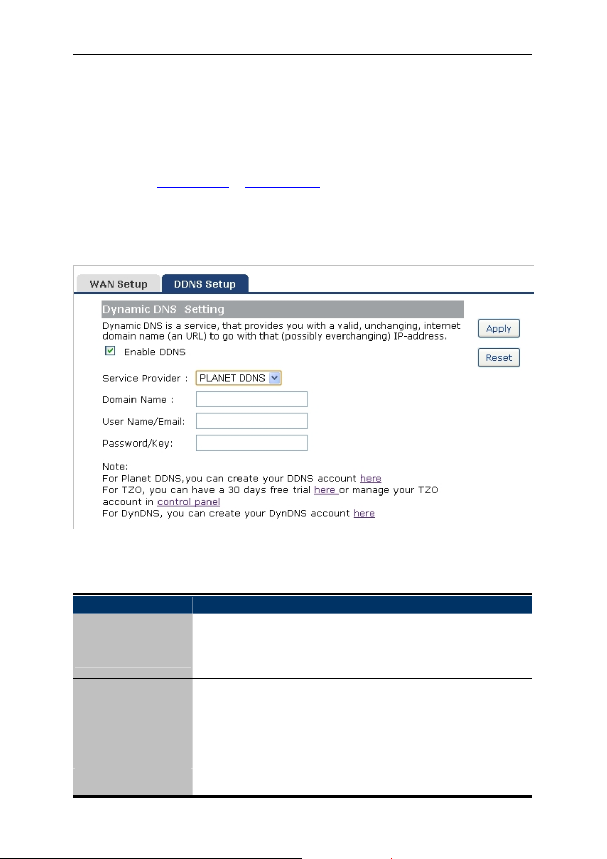
5.3.2 DDNS
The Wireless Router offers the DDNS (Dynamic Domain Name System) feature, which allows the
hosting of a website, FTP server, or e-mail server with a fixed domain name (named by yourself) and a
dynamic IP address, and then your friends can connect to your server by entering your domain name
no matter what your IP address is. Before using this feature, you need to sign up for DDNS service
providers such as PLANET DDNS
or www.dyndns.org. The Dynamic DNS client service provider will
give you a password or key.
Choose menu “WAN Setup DDNS Setup” to configure the settings about Dynamic DNS. After the
configuration, please click the “Apply” button to save the settings.
Figure 5-3-2 DDNS Setup screenshot
The page includes the following fields:
Object Description
Enable DDNS
Service Provider
Check the box to enable the Dynamic DNS function.
Select the DDNS service provider from the drop-down menu, such as
PLANET DDNS, DynDNS or TZO.
Domain Name
Enter the domain name you have registered from the DDNS service
provider.
User Name/Email
Enter the user name or email you have registered from the DDNS
service provider.
Password/Key
Enter the password you have registered from the DDNS service provider.
-38-
Page 46
User’s Manual of WNRT-633
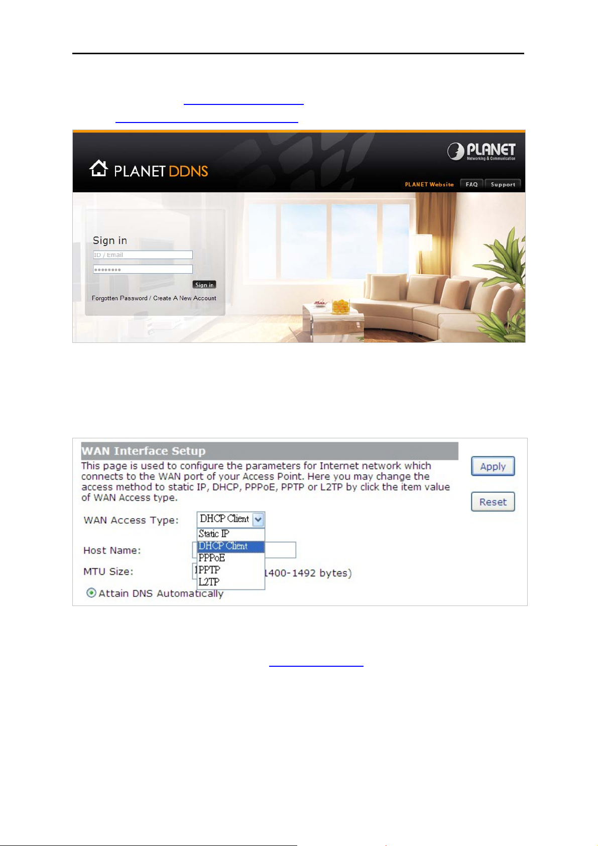
5.3.3 Planet DDNS
First of all, please go to http://www.planetddns.com to register a Planet DDNS account, and refer to
the FAQ (http://www.planetddns.com/index.php/faq
) for how to register a free account.
Figure 5-3-3 Planet DDNS Website
When you finish your DDNS account, please return to WAN Setup -> WAN Setup to set up your WAN
type which can be connected to external network.
Figure 5-3-4 WAN Settings
To select dynamic DNS Service Provider www.planetddns.com
Figure 5-3-5.
, the page will appear as shown in
-39-
Page 47
User’s Manual of WNRT-633
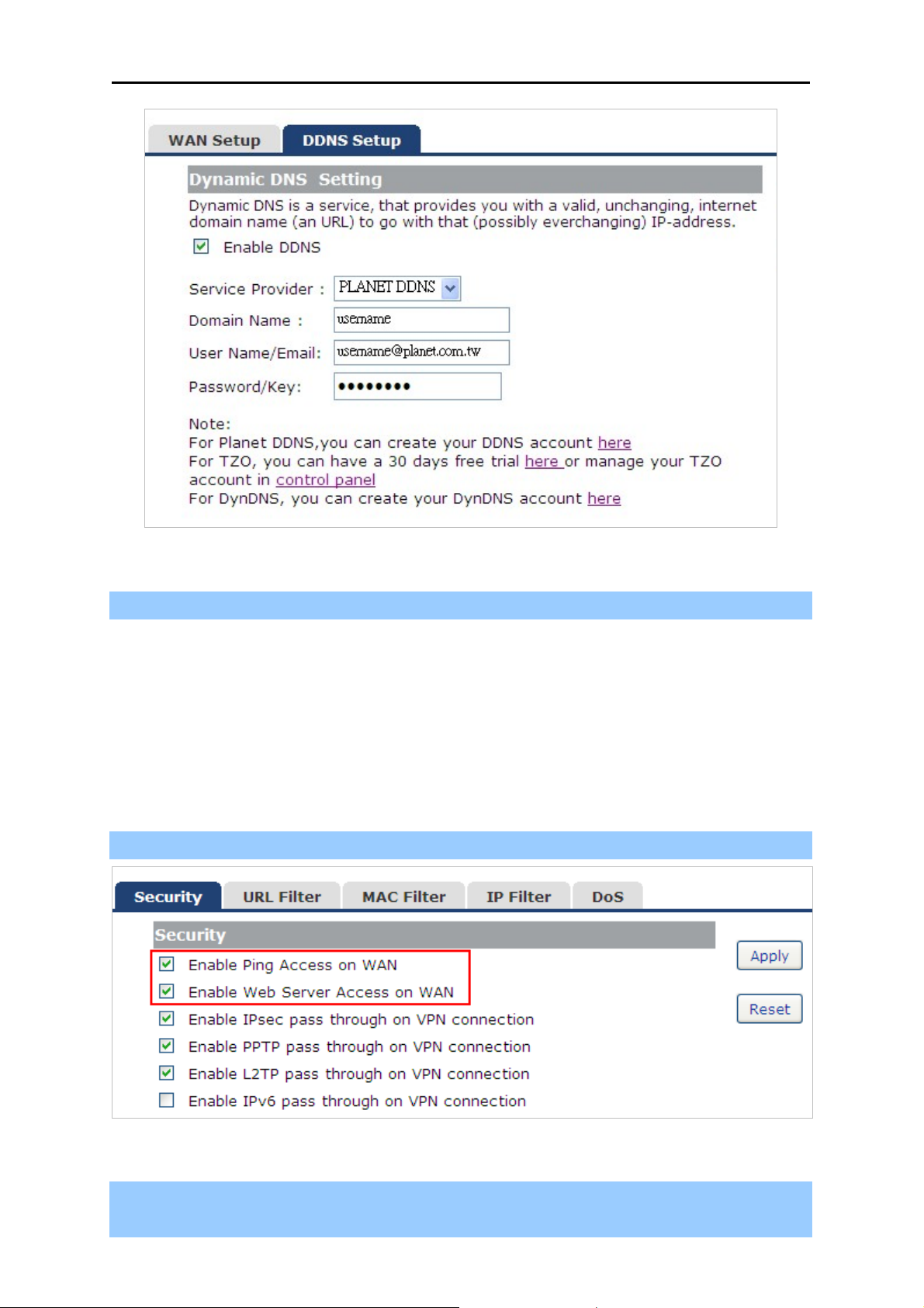
Figure 5-3-5 PlanetDDNS Settings
Step 1. Enable DDNS, and then select “PLANET DDNS”.
To set up for DDNS, follow these instructions:
Step 1. Type the Domain Name you received from dynamic DNS service provider.
Step 2. Type the User Name for your DDNS account.
Step 3. Type the Password for your DDNS account.
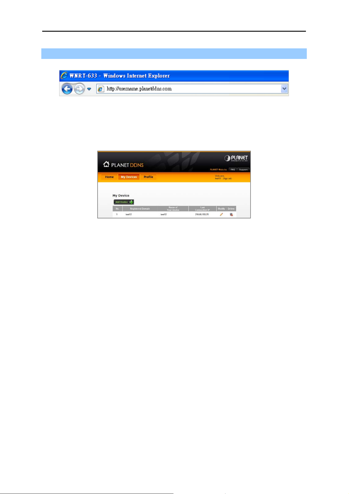
Step 2. Go to “Security Setup-> Security” page to allow remote access from WAN port.
Figure 5-3-6 Enable Web Access on WAN
Step 3. Apply the settings, and ensure you have connected the WAN port to the internet by Ethernet
cable.
-40-
Page 48
User’s Manual of WNRT-633
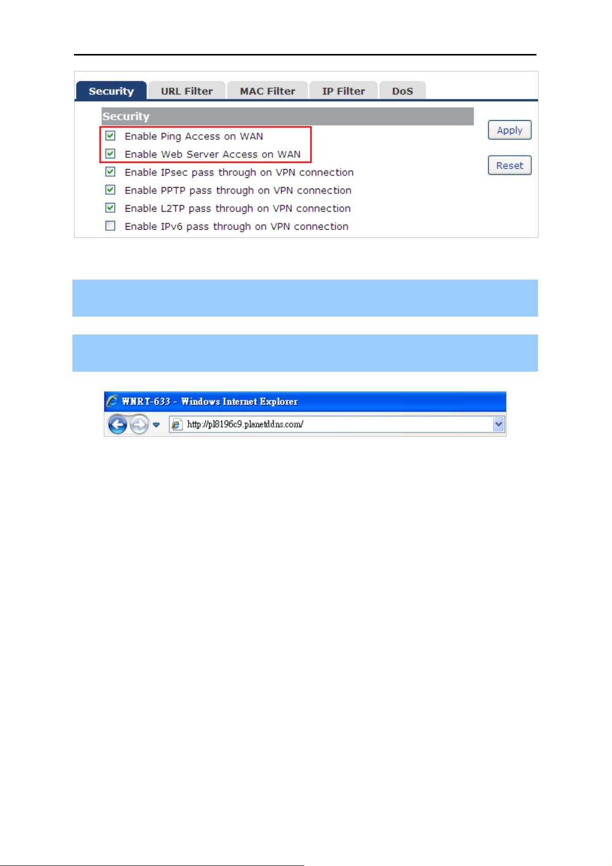
Step 4. In a remote computer, enter the Domain Name to the internet browser’s address bar.
Figure 5-3-7 Login PLANET DDNS
Lastly you can go to My Devices page of Planet DDNS website to check if the “Last Connection IP” is
displayed. This indicates your DDNS service is working properly.
Figure 5-3-8 My Devices
-41-
Page 49

User’s Manual of WNRT-633
5.3.4 Planet EasyDDNS
PLANET Easy DDNS is a way help to get your Domain Name with just one click. You can just login to
the Web Management Interface of your devices, check the DDNS menu and just enable it.
Once you enabled the Easy DDNS, your PLANET Network Device will use the format PLxxxxxx where
xxxxxx is the last 6 characters of your MAC address that can be found on the Web page or bottom
label of the device. (For example: 00-30-4F-77-88-17, it will be converted into
PL778817.pl
anet
ddns.com)
To use Planet EasyDDNS service, please refer to the procedure listed as following.
Step 1. Select “Enable Easy DDNS” to use the Planet Easy DDNS service.
Figure 5-1-9 Planet EasyDDNS Settings
Domain Name:Display the specified domain name for this device. (format: plxxxxxx.planetddns.com,
xxxxxx is the last six-digit of the WAN Port MAC address)
Step 2. Go to “Security Setup-> Security” page to allow remote access from WAN port.
-42-
Page 50
User’s Manual of WNRT-633
Figure 5-3-10 Enable Web Access on WAN
Step 3. Apply the settings, and ensure you have connected the WAN port to the internet by Ethernet
cable.
Step 4. In a remote computer, enter the Domain Name displayed in the Figure 5-3-9 to the internet
browser’s address bar.
Figure 5-3-11 Login Easy DDNS
-43-
Page 51
User’s Manual of WNRT-633
5.4 LAN Setup
There are two ways to assign IP addresses to computers:
Static IP Address (set the IP address for every computer manually)
Dynamic IP Address (IP address of computers will be assigned by a router automatically)
It is recommended for most of computers to use dynamic IP address, because it will save a lot of time
on setting IP addresses for every computer, especially when there are a lot of computers in the
network; for servers and network devices which will provide services to other computers and users that
come from Internet, static IP address should be useful, so other computers are able to locate the
server. You can configure the IP parameters of the LAN on the screen as below.
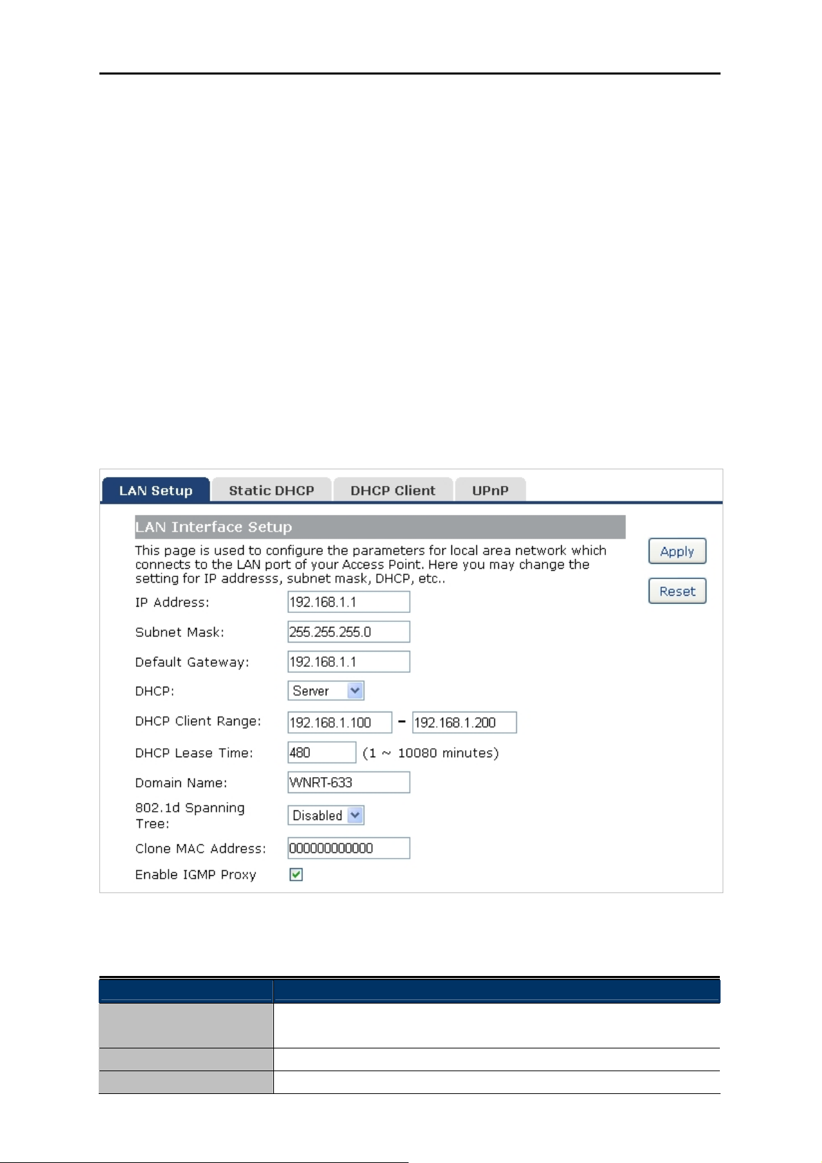
5.4.1 LAN Interface Setup
Choose menu “LAN Setup LAN Interface”, and you can configure the parameters for LAN (Local
Area Network). After the configuration, please click the “Apply” button to save the settings.
Figure 5-4-1 LAN Interface Setup screenshot
The page includes the following fields:
Object Description
IP Address The LAN IP address of the WNRT-633, and default is 192.168.1.1. You
can change it according to your request.
Subnet Mask Default is 255.255.255.0. You can change it according to your request.
Default Gateway Default is 192.168.1.1. You can change it according to your request.
-44-
Page 52
User’s Manual of WNRT-633
DHCP You can select one of Disable, Client, and Server. Default is Server,
that the WNRT-633 can assign IP addresses to the computers
automatically.
DHCP Client Range For the Server mode, you must enter the DHCP client IP address
range in the field. And you can click the “Show Client” button to show
the Active DHCP Client Table.
Static DHCP Click the “Set Static DHCP” button, and you can reserve some IP
addresses for those network devices with the specified MAC
addresses anytime when they request IP addresses.
Domain Name Default is Router.
802.1d Spanning Tree You can enable or disable the spanning tree function.
Clone MAC Address You can input a MAC address here for using clone function.
If you change the device’s LAN IP address, you must enter the new one in your
browser to get back to the web-based configuration utility. And LAN PCs’ gateway
must be set to this new IP for successful Internet connection.
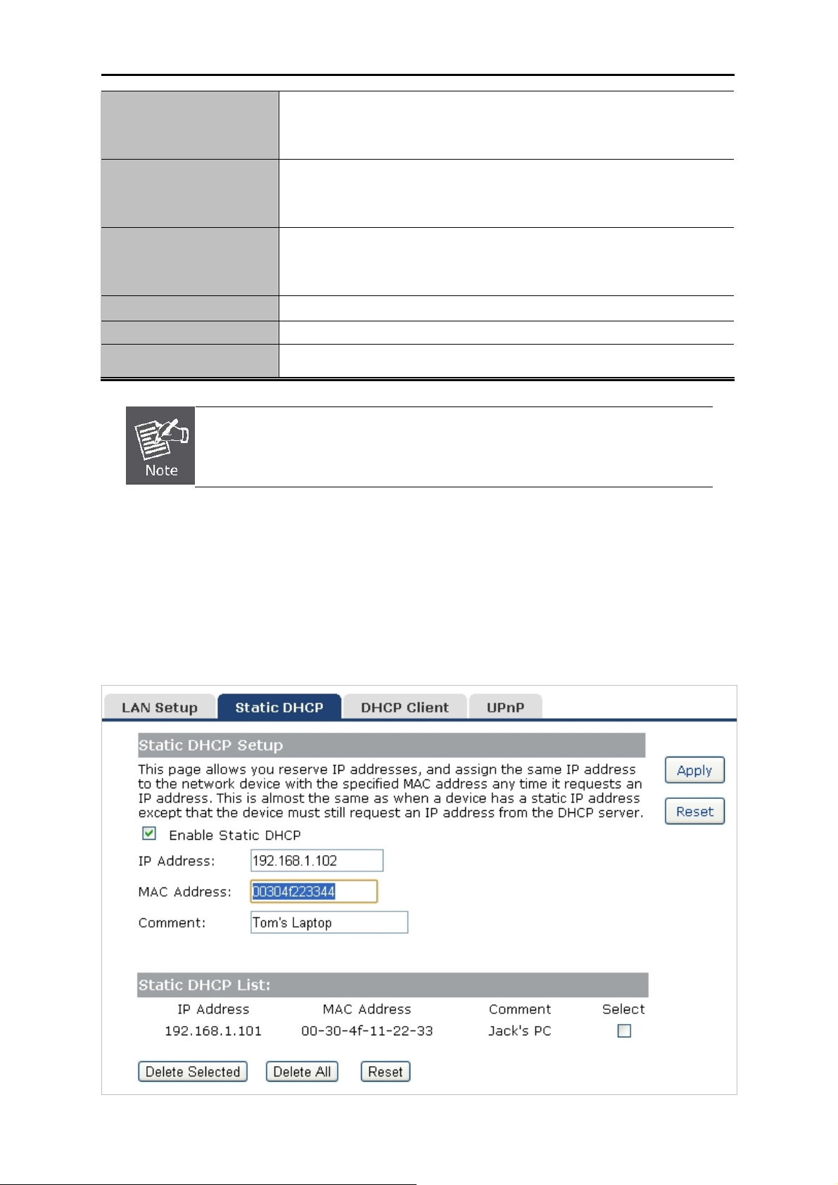
5.4.2 Static DHCP
This page allows you reserve IP addresses, and assign the same IP address to the network device
with the specified MAC address any time it requests an IP address. This is almost the same as when a
device has a static IP address except that the device must still request an IP address from the DHCP
server.
Figure 5-4-2 Static DHCP Setup screenshot
-45-
Page 53

User’s Manual of WNRT-633
The page includes the following fields:
Object Description
IP Address
MAC Address
Enter the IP address which needs to be bound.
Enter the MAC address of the computer you want to assign the above IP
address.
Comment
You can add some comment for this item.
Click “Apply” to add the entry in the list.
5.4.3 DHCP Client
This table shows the assigned IP address, MAC address and time expired for each DHCP leased
client.
Figure 5-4-3 DHCP Client screenshot
The page includes the following fields:
Object Description
IP Address The IP address that the Router has allocated to the DHCP client.
MAC Address The MAC address of the DHCP client
Time Expired(s) Remaining time for a corresponding IP address lease.
-46-
Page 54

User’s Manual of WNRT-633
5.4.4 UPnP
The UPnP feature allows the devices, such as Internet computers, to access the local host resources
or devices as needed. UPnP devices can be automatically discovered by the UPnP service application
on the LAN.
Figure 5-4-4 UPnP Setting screenshot
The page includes the following fields:
Object Description
UPnP
Local IP
Protocol
Port
Check on to enable UPnP function.
The IP address of an internal host that receives/sends responses.
Indicates whether to perform TCP or UDP port forwarding
Port on host side.
The pages also list the forwarding port added by UPnP Service.
-47-
Page 55
User’s Manual of WNRT-633
5.5 Wireless
The Wireless menu contains submenus of the settings about wireless network. Please refer to the
following sections for the details.
Figure 5-5-1
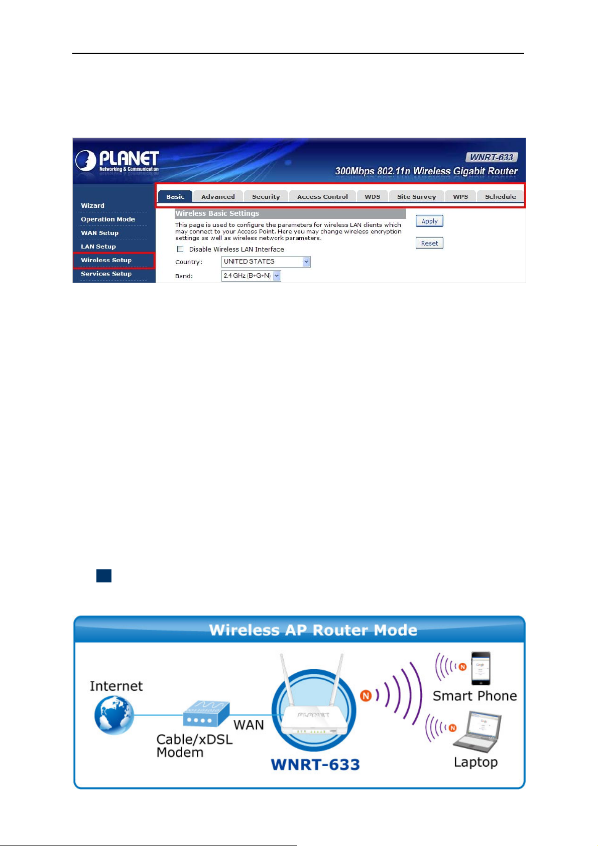
5.5.1 Basic Settings
Choose menu “Wireless Setup Basic”, and you can configure the basic settings for the wireless
network on this page. After the configuration, please click the “Apply” button to save the settings.
First of all, the Wireless Router supports multiple wireless modes for different network applications,
which includes:
AP
Client
WDS
AP+WDS
It is so easy to combine the WNRT-633 with the existing wired network. The WNRT-633 definitely
provides a total network solution for the home and the SOHO users.
AP
Standard wireless Access Point
-48-
Page 56

User’s Manual of WNRT-633
Figure 5-5-2 Wireless Basic Settings-AP mode screenshot
The page includes the following fields:
Object Description
Disable Wireless LAN
Check the box to disable the wireless function.
Interface
Country
Select your region from the pull-down list.
This field specifies the region where the wireless function of the Router
can be used. It may be illegal to use the wireless function of the Router
-49-
Page 57

User’s Manual of WNRT-633
in a region other than one of those specified in this field. If your country
or region is not listed, please contact your local government agency for
assistance.
Band Select the desired mode. Default is “2.4GHz (B+G+N)”. It is strongly
recommended that you set the Band to “2.4GHz (B+G+N)”, and all of
802.11b, 802.11g, and 802.11n wireless stations can connect to the
WNRT-633.
2.4 GHz (B): 802.11b mode, rate is up to 11Mbps
2.4 GHz (G): 802.11g mode, rate is up to 54Mbps
2.4 GHz (N): 802.11n mode, rate is up to 300Mbps(2T2R)
2.4 GHz (B+G): 802.11b/g mode, rate is up to 11Mbps or 54Mbps
2.4 GHz (G+N): 802.11g/n mode, rate is up to 54Mbps or 300Mbps
2.4 GHz (B+G+N): 802.11b/g/n mode, rate is up to 11Mbps,
54Mbps, or 300Mbps
Mode
There are four kinds of wireless mode selections:
AP
Client
WDS
AP+WDS
If you select WDS or AP+WDS, please click “WDS Settings” submenu
for the related configuration. Furthermore, click the “Multiple AP”
button to enable multiple SSID function.
SSID
The ID of the wireless network. User can access the wireless network
through it only. However, if you switch to Client Mode, this field
becomes the SSID of the AP you want to connect with.
Default: WNRT-633
Channel Width You can select 20MHz or 40MHz.
Control Sideband You can select Upper or Lower.
Channel Number
Broadcast SSID
You can select the operating frequency of wireless network.
If you enable “Broadcast SSID”, every wireless station located within
the coverage of the WNRT-633 can discover its signal easily. If you are
building a public wireless network, enabling this feature is
recommended. In private network, disabling “Broadcast SSID” can
provide better wireless network security.
Data Rate
Default is “Enabled”.
Set the wireless data transfer rate to a certain value. Since most of
wireless devices will negotiate with each other and pick a proper data
transfer rate automatically, it’s not necessary to change this value
unless you know what will happen after modification.
Default is “Auto”.
-50-
Page 58

User’s Manual of WNRT-633
Associated Clients
Click the “Show Active Clients” button to show the status table of
active wireless clients.
Enable Universal
Repeater Mode
(Acting as AP and client
simultaneously)
Universal Repeater is a technology used to extend wireless coverage.
To enable Universal Repeater Mode, check the box and enter the
SSID you want to broadcast in the field below. Then please click
“Security” submenu for the related settings of the AP you want to
connect with.
Client (Infrastructure)
Combine the Wireless Router to the Ethernet devices such as TV, Game player, or HDD&DVD, to
make them be wireless stations.
-51-
Page 59
User’s Manual of WNRT-633
Figure 5-5-3 Wireless Basic Settings-Client mode screenshot
The page includes the following fields:
Object Description
Disable Wireless LAN
Check the box to disable the wireless function.
Interface
Country
Select your region from the pull-down list.
Band Select the desired mode. Default is “2.4GHz (B+G+N)”. It is strongly
recommended that you set the Band to “2.4GHz (B+G+N)”, and all of
802.11b, 802.11g, and 802.11n wireless stations can connect to the
WNRT-633.
2.4 GHz (B): 802.11b mode, rate is up to 11Mbps
2.4 GHz (G): 802.11g mode, rate is up to 54Mbps
2.4 GHz (N): 802.11n mode, rate is up to 300Mbps(2T2R)
2.4 GHz (B+G): 802.11b/g mode, rate is up to 11Mbps or 54Mbps
2.4 GHz (G+N): 802.11g/n mode, rate is up to 54Mbps or 300Mbps
2.4 GHz (B+G+N): 802.11b/g/n mode, rate is up to 11Mbps,
54Mbps, or 300Mbps
Mode
There are four kinds of wireless mode selections:
AP
Client
WDS
AP+WDS
If you select WDS or AP+WDS, please click “WDS Settings” submenu
for the related configuration. Furthermore, click the “Multiple AP”
button to enable multiple SSID function.
Network Type In Infrastructure, the wireless LAN serves as a wireless station. And
the user can use the PC equipped with the WNRT-633 to access the
wireless network via other access points. In Ad hoc, the wireless LAN
-52-
Page 60
User’s Manual of WNRT-633
will use the Ad-hoc mode to operate.
Default is “Infrastructure”.
Note: only while the wireless mode is set to “Client”, then the Network
Type can be configured.
SSID
Broadcast SSID
Data Rate
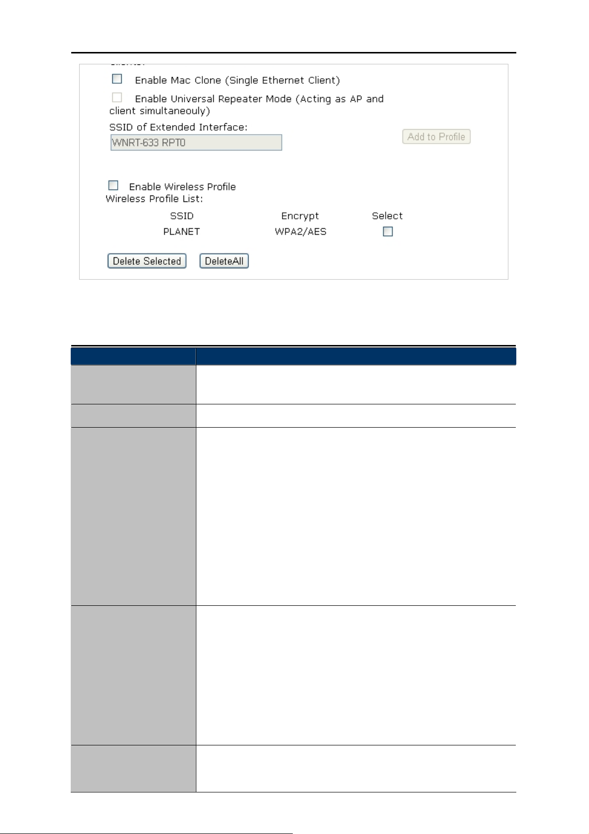
Enable Mac Clone
(Single Ethernet Client)
The ID of the wireless network. User can access the wireless network
through it only. However, if you switch to Client Mode, this field
becomes the SSID of the AP you want to connect with.
Default: WNRT-633
If you enable “Broadcast SSID”, every wireless station located within
the coverage of the WNRT-633 can discover its signal easily. If you are
building a public wireless network, enabling this feature is
recommended. In private network, disabling “Broadcast SSID” can
provide better wireless network security.
Default is “Enabled”.
Set the wireless data transfer rate to a certain value. Since most of
wireless devices will negotiate with each other and pick a proper data
transfer rate automatically, it’s not necessary to change this value
unless you know what will happen after modification.
Default is “Auto”.
Enable Mac Clone.
WDS
Connect this Wireless Router with up to 8 WDS-capable wireless routers to expand the scope of
network.
-53-
Page 61
User’s Manual of WNRT-633
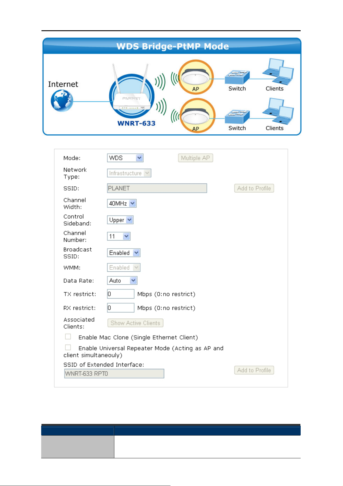
Figure 5-5-4 Wireless Basic Settings-WDS mode screenshot
The page includes the following fields:
Object Description
Disable Wireless LAN
Check the box to disable the wireless function.
Interface
-54-
Page 62

User’s Manual of WNRT-633
Country
Select your region from the pull-down list.
This field specifies the region where the wireless function of the Router
can be used. It may be illegal to use the wireless function of the Router
in a region other than one of those specified in this field. If your country
or region is not listed, please contact your local government agency for
assistance.
Band Select the desired mode. Default is “2.4GHz (B+G+N)”. It is strongly
recommended that you set the Band to “2.4GHz (B+G+N)”, and all of
802.11b, 802.11g, and 802.11n wireless stations can connect to the
WNRT-633.
2.4 GHz (B): 802.11b mode, rate is up to 11Mbps
2.4 GHz (G): 802.11g mode, rate is up to 54Mbps
2.4 GHz (N): 802.11n mode, rate is up to 300Mbps(2T2R)
2.4 GHz (B+G): 802.11b/g mode, rate is up to 11Mbps or 54Mbps
2.4 GHz (G+N): 802.11g/n mode, rate is up to 54Mbps or 300Mbps
2.4 GHz (B+G+N): 802.11b/g/n mode, rate is up to 11Mbps,
54Mbps, or 300Mbps
Mode
There are four kinds of wireless mode selections:
AP
Client
WDS
AP+WDS
If you select WDS or AP+WDS, please click “WDS Settings” submenu
for the related configuration. Furthermore, click the “Multiple AP”
button to enable multiple SSID function.
Channel Width You can select 20MHz or 40MHz.
Control Sideband You can select Upper or Lower.
Channel Number
Data Rate
You can select the operating frequency of wireless network.
Set the wireless data transfer rate to a certain value. Since most of
wireless devices will negotiate with each other and pick a proper data
transfer rate automatically, it’s not necessary to change this value
unless you know what will happen after modification.
Default is “Auto”.
-55-
Page 63
User’s Manual of WNRT-633
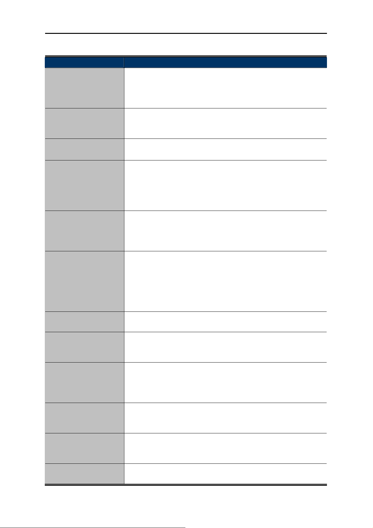
AP+ WDS
Connect this Wireless Router with up to 8 WDS-capable wireless routers, and as another AP to
provide service for all wireless stations within its coverage.
Figure 5-5-5 Wireless Basic Settings-AP+WDS mode screenshot
-56-
Page 64

The page includes the following fields:
Object Description
Disable Wireless LAN
Check the box to disable the wireless function.
Interface
User’s Manual of WNRT-633
Country
Select your region from the pull-down list.
This field specifies the region where the wireless function of the Router
can be used. It may be illegal to use the wireless function of the Router
in a region other than one of those specified in this field. If your country
or region is not listed, please contact your local government agency for
assistance.
Band Select the desired mode. Default is “2.4GHz (B+G+N)”. It is strongly
recommended that you set the Band to “2.4GHz (B+G+N)”, and all of
802.11b, 802.11g, and 802.11n wireless stations can connect to the
WNRT-633.
2.4 GHz (B): 802.11b mode, rate is up to 11Mbps
2.4 GHz (G): 802.11g mode, rate is up to 54Mbps
2.4 GHz (N): 802.11n mode, rate is up to 300Mbps(2T2R)
2.4 GHz (B+G): 802.11b/g mode, rate is up to 11Mbps or 54Mbps
2.4 GHz (G+N): 802.11g/n mode, rate is up to 54Mbps or 300Mbps
2.4 GHz (B+G+N): 802.11b/g/n mode, rate is up to 11Mbps,
54Mbps, or 300Mbps
Mode
There are four kinds of wireless mode selections:
AP
Client
WDS
AP+WDS
If you select WDS or AP+WDS, please click “WDS Settings” submenu
for the related configuration. Furthermore, click the “Multiple AP”
button to enable multiple SSID function.
SSID
The ID of the wireless network. User can access the wireless network
through it only. However, if you switch to Client Mode, this field
becomes the SSID of the AP you want to connect with.
Default: WNRT-633
Channel Width You can select 20MHz or 40MHz.
Control Sideband You can select Upper or Lower.
Channel Number
Broadcast SSID
You can select the operating frequency of wireless network.
If you enable “Broadcast SSID”, every wireless station located within
the coverage of the WNRT-633 can discover its signal easily. If you are
building a public wireless network, enabling this feature is
recommended. In private network, disabling “Broadcast SSID” can
provide better wireless network security.
-57-
Page 65

Default is “Enabled”.
User’s Manual of WNRT-633
Data Rate
Set the wireless data transfer rate to a certain value. Since most of
wireless devices will negotiate with each other and pick a proper data
transfer rate automatically, it’s not necessary to change this value
unless you know what will happen after modification.
Default is “Auto”.
Associated Clients
Click the “Show Active Clients” button to show the status table of
active wireless clients.
Enable Universal
Repeater Mode
(Acting as AP and client
simultaneously)
Universal Repeater is a technology used to extend wireless coverage.
To enable Universal Repeater Mode, check the box and enter the
SSID you want to broadcast in the field below. Then please click
“Security” submenu for the related settings of the AP you want to
connect with.
5.5.2 Advanced
Choose menu “Wireless Setup Advanced Settings”, and you can configure the advanced settings
for the wireless network on this page. After the configuration, please click the “Apply” button to save
the settings.
Figure 5-5-6 Wireless Advanced Settings
-58-
Page 66
User’s Manual of WNRT-633
The page includes the following fields:
Object Description
Fragment Threshold You can specify the maximum size of packet during the fragmentation
of data to be transmitted. If you set this value too low, it will result in
bad performance.
Default is “2346”.
RTS Threshold When the packet size is smaller than the RTS threshold, the access
point will not use the RTS/CTS mechanism to send this packet.
Default is “2347”.
Beacon Interval The interval of time that this access point broadcast a beacon. Beacon
is used to synchronize the wireless network. Default is “100”.
Preamble Type Preamble type defines the length of CRC block in the frames during
the wireless communication. “Short Preamble” is suitable for high
traffic wireless network. “Long Preamble” can provide more reliable
communication.
Default is “Long Preamble”.
IAPP IAPP (Inter-Access Point Protocol) enabled is recommendation that
describes an optional extension to IEEE 802.11 that provides wireless
access-point communications among multivendor systems.
Default is “Enabled”.
Protection It is recommended to enable the protection mechanism. This
mechanism can decrease the rate of data collision between 802.11b
and 802.11g wireless stations. When the protection mode is enabled,
the throughput of the AP will be a little lower due to many of frame
traffic should be transmitted.
Default is “Disabled”.
Aggregation It is a function where the values of multiple rows are grouped together.
Default is “Enabled”
Short GI It is used to set the time that the receiver waits for RF reflections to
settle out before sampling data.
Default is “Enabled”
WLAN Partition This feature also called “WLAN isolation” or “Block Relay”. If this is
enabled, wireless clients cannot exchange data through the
WNRT-633.
Default is “Disabled”.
STBC Activate Space Time Blocking Code (STBC) which does not need
channel statement information (CSI).
Default Setting: "Disabled"
20/40MHz Coexist Configure 20/40MHz coexisting scheme.
If you set up as "Enabled", "20MHz" and "40MHz" will coexist.
Default Setting: "Disabled"
RF Output Power Users can adjust the wireless output power here.
Default is “100%”.
-59-
Page 67
User’s Manual of WNRT-633
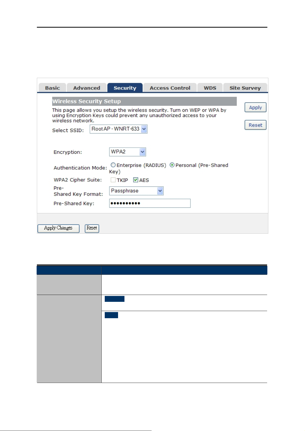
5.5.3 Security
Choose menu “Wireless Security”, and you can configure the settings of wireless security for the
wireless network on this page. After the configuration, please click the “Apply” button to save the
settings.
Figure 5-5-7 Wirel
The page includes the following fields:
Object Description
Select SSID
Select the SSID you want to configure the wireless security function,
which includes the root one and the client one.
Encryption
Disable:
No security setup for wireless connection.
WEP:
It is based on the IEEE 802.11 standard. And the default setting of
authentication is Automatic, which can select Open System or
Shared Key authentication type automatically based on the wireless
station's capability and request. Furthermore, you can select Key
Length and enter 10 & 26 Hexadecimal digits (any combination of
0-9, a-f, A-F, zero key is not promoted) or 5 & 13 ASCII characters in
the Encryption Key field.
e
ss Security Setup screenshot
-60-
Page 68

User’s Manual of WNRT-633
WPA:
WPA is a medium level encryption and is supported by most wireless
devices and operating systems.
WPA2:
WPA2 is a high level encryption and is s
s and operating systems.
device
upported by most wireless
WPA / WPA2 / WPA-Mixed:
WPA Mixed Mode allows the use of both WPA and WPA2 at the same
time.
Authentication Mode
Enterprise (RADIUS)
When you select the authentication mode based on Enterprise (Radius
Server), please enter the IP Address, Port, and Password of the
Radius Server.
Personal (Pr ed Key)
When you
e-Shar
select the other authentication mode based on Personal
(Pre-Shared Key), please enter at least 8 ASCII characters
(Passphrase) or 64 Hexadecimal characters. All of the Cipher Suites
support TKIP and AES.
802.1x Authentication
Enable 802.1x authentication function, then please enter the IP
Address, Port, and Password of the Radius Server.
5 ro
.5.4 Access Cont l
Choose menu “Wireless
specified MAC address to co
Access Control”, you can choose to allow or deny the computer of
nnect with the WNRT-633 on this page. After the configuration, please
click the “Apply” button to save the settings.
Figure 5-5-8 Wireless Access Control Setup screenshot
-61-
Page 69

The page includes the following fields:
Object Description
Wireless Access
Control Mode
You can choose to set the Allowed-List, Denied-List, or disable this
function.
User’s Manual of WNRT-633
MAC Address
Comment
Current Access Control
List
Enter the MAC address you want to allow or deny to connect to the
WNRT-633 in the field.
You can make some comment on each MAC address on the list.
You can select some MAC address, and click the “Delete Selected”
button to delete it.
-62-
Page 70
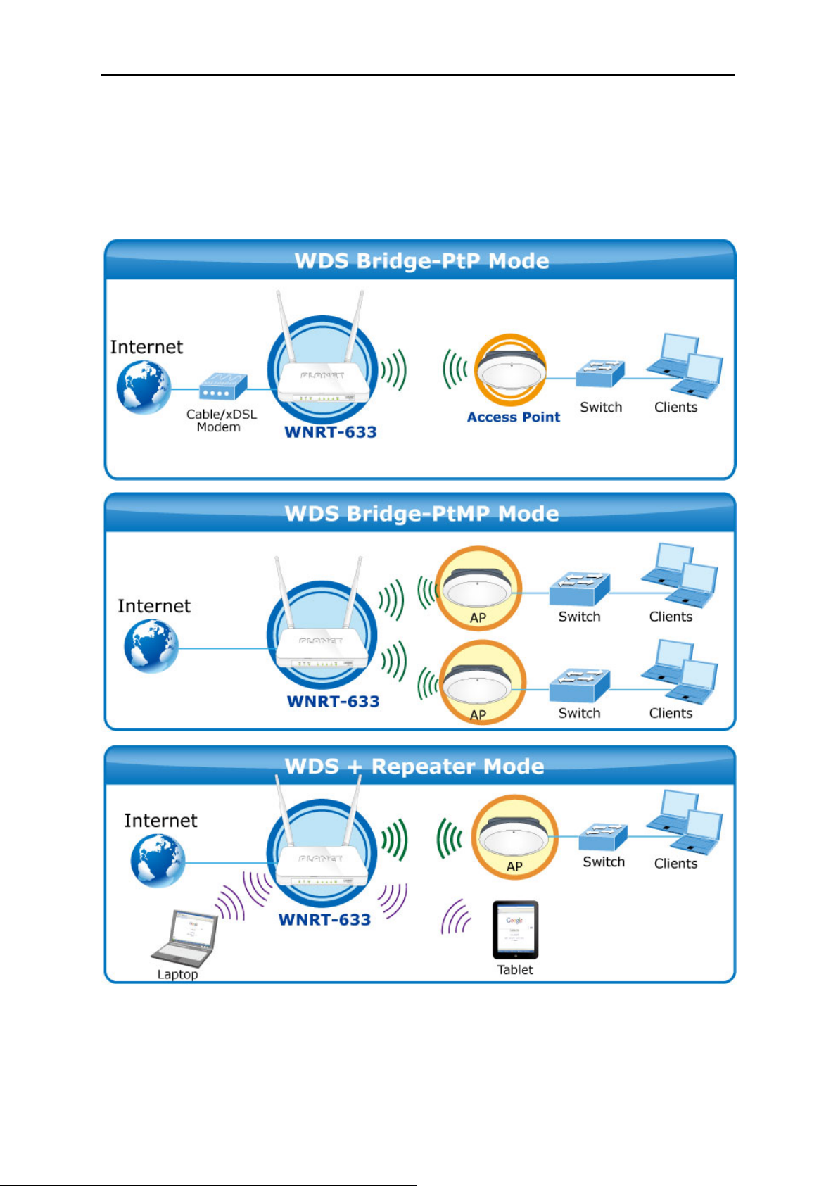
User’s Manual of WNRT-633
5.5.5 WDS Settings
Wireless Distribution System (WDS) uses wireless media to communicate with other APs, like the
Ethernet does. To do this, you must set these APs in the same channel and set MAC address of
other APs which you want to communicate with in the table and then enable the WDS.
Before configuring the WDS Setting page, you have to select the wireless mode to “WDS” on the
Wireless -> Basic web page.
-63-
Page 71

User’s Manual of WNRT-633
Figure 5-5-9 WDS Settings
Choose menu “Wireless WDS Settings”, and you can configure WDS to connect the WNRT-633
with another AP on this page. After the configuration, please click the “Apply” button to save the
settings.
Figure 5-5-10 WDS Settings
-64-
Page 72

User’s Manual of WNRT-633
The page includes the following fields:
Object Description
Enable WDS Check the box to enable the WDS function. Please select WDS or
AP+WDS in the Mode of Wireless Basic Settings before you enable
WDS on this page.
MAC Address You can enter the MAC address of the AP you want to connect with.
Data Rate Default is “Auto”.
Comment You can make some comment for each MAC address on the list.
Set Security Click the “Set Security” button, then configure the wireless security
parameters of the AP you want to connect via WDS.
Show Statics Click the “Show Statics” button to show the WDS AP.
Current WDS AP List You can select some MAC address of the AP, and click the “Delete
Selected” button to delete it.
1. WDS feature can only be implemented between 2 wireless devices that both
support the WDS feature. Plus, SSID, channel, security settings and security
key must be the same on both such devices.
2. To encrypt your wireless network, see sections 5.5.3. Do remember to reboot the
device after you save your wireless security settings; otherwise, the WDS feature
may not function.
5.5.6 Site Survey
Choose menu “Wireless Site Survey” to scan the available local AP. If any Access Point is found,
you could choose any one to connect with manually when the Client Mode is enabled.
Figure 5-5-11 Wireless Site Survey
-65-
Page 73

User’s Manual of WNRT-633
5.5.7 WPS
WPS (Wi-Fi Protected Setup) is designed to ease setup of security Wi-Fi networks and subsequently
network management. This Wireless Router supports WPS features for AP mode, AP+WDS mode,
Infrastructure-Client mode, and the wireless root interface of Universal Repeater mode.
Simply enter a PIN code or press the software PBC button or hardware WPS button (if any) and a
secure wireless connection is established.
PBC: If you find the WPS LED blinking for 2 minutes after you press the hardware WPS
button on the device, it means that PBC encryption method is successfully enabled.
And an authentication will be performed between your router and the
WPS/PBC-enabled wireless client device during this time; if it succeeds, the wireless
client device connects to your device, and the WPS LED turns off. Repeat steps
mentioned above if you want to connect more wireless client devices to the device.
PIN:To use this option, you must know the PIN code from the wireless client and enter it in
corresponding field on your device while using the same PIN code on client side for
such connection.
Choose menu “Wireless WPS”, and you can configure the setting for WPS. After the configuration,
please click the “Apply” button to save the settings.
Figure 5-5-12 WPS (Wi-Fi Protected Setup)
-66-
Page 74
The page includes the following fields:
Object Description
User’s Manual of WNRT-633
Disable WPS
WPS Status
Self-PIN Number
Push Button
Configuration
Client PIN Number
The WPS encryption can be implemented only between your Router and another
WPS-capable device.
You can check the box to disable the WPS function.
Here you can check if the connection via WPS is established or not.
It is the PIN number of the WNRT-633 here.
Click the “Start PBC”, and then activate WPS as well in the client
device within 2 minutes.
In addition to the PBC method, you can also use the PIN method to
activate the WPS. Just enter the PIN number of the client device in the
field, and click the “Start PIN” button.
-67-
Page 75
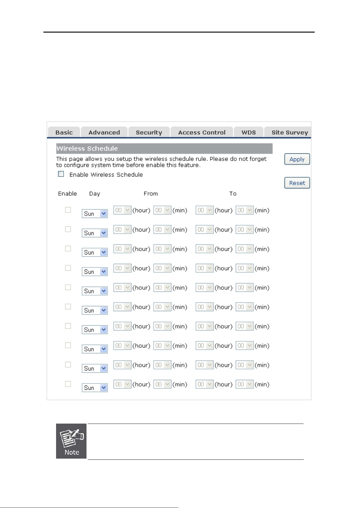
User’s Manual of WNRT-633
5.5.8 Schedule
Wireless Schedules will enable or disable your wireless access at a set time based on your predefined
schedule. This feature is often used for restricting access to all users (such as children, employees,
guests) during specific times of the day for parental control or security reasons.
Choose menu “Wireless Schedule”, and you can configure the schedule rule of enabling wireless
function. After the configuration, please click the “Apply” button to save the settings.
Figure 5-5-13 Wireless Schedule
When setting the Wireless Schedule, it is important to ensure that your System
Clock settings have been configured. If they have not, your Wireless Schedule
will not function correctly.
-68-
Page 76

User’s Manual of WNRT-633
5.6 Service Setup
5.6.1 Port Forwarding
Choose menu “Service Setup Port Forwarding”, and you can configure to re-direct a particular
range of service port numbers from the Internet network to a particular LAN IP address. It helps users
to host some servers behind the firewall. After the configuration, please click the “Apply” button to save
the settings.
Figure 5-6-1 Port Forwarding
The page includes the following fields:
Object Description
Enable Port Forwarding Enable Port Forwarding function
IP Address Add LAN IP address of specified host or server on the private local
network
Protocol Select the port number protocol type (TCP, UDP or both). If you are
unsure, then leave it to the default both protocol
Port Range Add ports you want to control. For TCP and UDP Services, enter the
beginning of the range of port numbers used by the service. If the
service uses a single port number, enter it in both the start and finish
fields.
Comment The description of this setting
-69-
Page 77
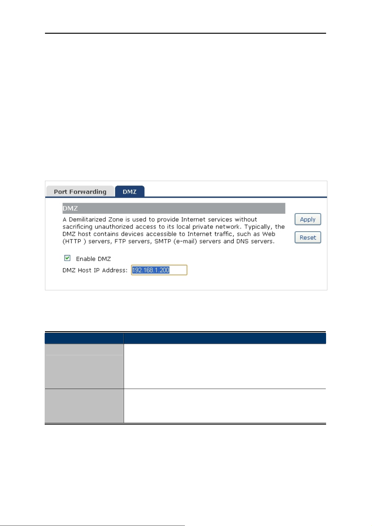
User’s Manual of WNRT-633
Check the “Select” box of which rule you want to delete, and then click the “Delete Selected” button to
delete it.
5.6.2 DMZ
This page allows you to set a De-militarized Zone (DMZ) to separate internal network and Internet.
Choose menu “Service Setup DMZ”, and you can configure the private IP address of DMZ. The
DMZ feature allows one local host to be exposed to the Internet for a special-purpose service such as
Internet gaming or video conferencing. After the configuration, please click the “Apply” button to save
the settings.
The page includes the following fields:
Object Description
Enable DMZ
Check the box to enable DMZ function. If the DMZ Host Function is
enabled, it means that you set up DMZ host at a particular computer to
be exposed to the Internet so that some applications/software,
especially Internet / online game can have two way connections.
DMZ Host IP Address
Enter the IP address of a particular host in your LAN which will receive
all the packets originally going to the WAN port / Public IP address
above.
Figure 5-6-2 DMZ
-70-
Page 78
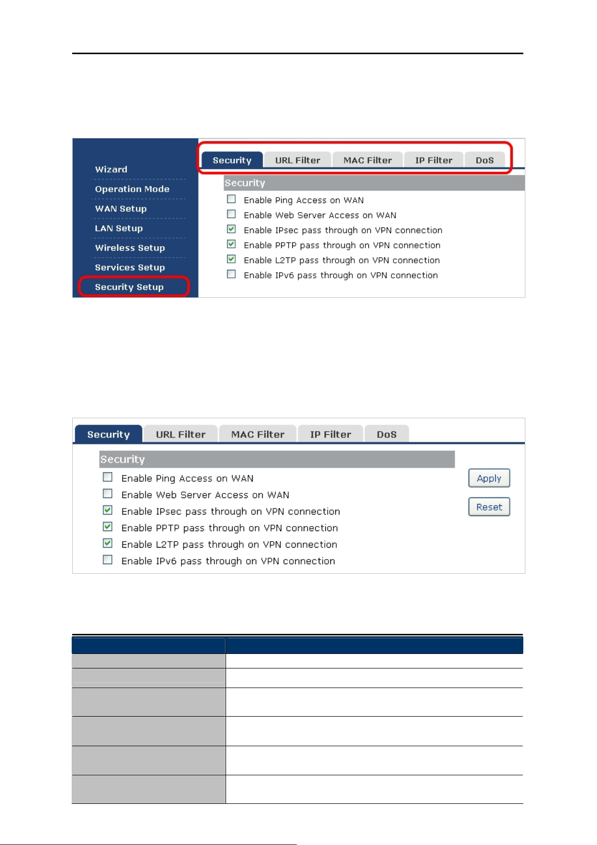
User’s Manual of WNRT-633
5.7 Security Setup
The Security Setup contains submenus of the settings about firewall and access filtering. Please refer
to the following sections for the details.
Figure 5-7-1
5.7.1 Security
The Wireless router provides extensive firewall protection by restricting connection parameters to limit
the risk of intrusion and defending against a wide array of common hacker attacks.
Figure 5-7-2
The page includes the following fields:
Object Description
Enable IGMP Proxy Check the box to enable the IGMP Proxy function.
Enable Ping Access on WAN Check the box to enable Ping access from the Internet Network.
Enable Web Server Access
on WAN
Enable IPsec pass through
on VPN connection
Enable PPTP pass through
on VPN connection
Enable L2TP pass through on
VPN connection
Check the box to enable the web server access of the
WNRT-633 from the Internet network.
Check the box to enable IPsec pass through function on VPN
connection.
Check the box to enable PPTP pass through function on VPN
connection.
Check the box to enable L2TP pass through function on VPN
connection.
-71-
Page 79
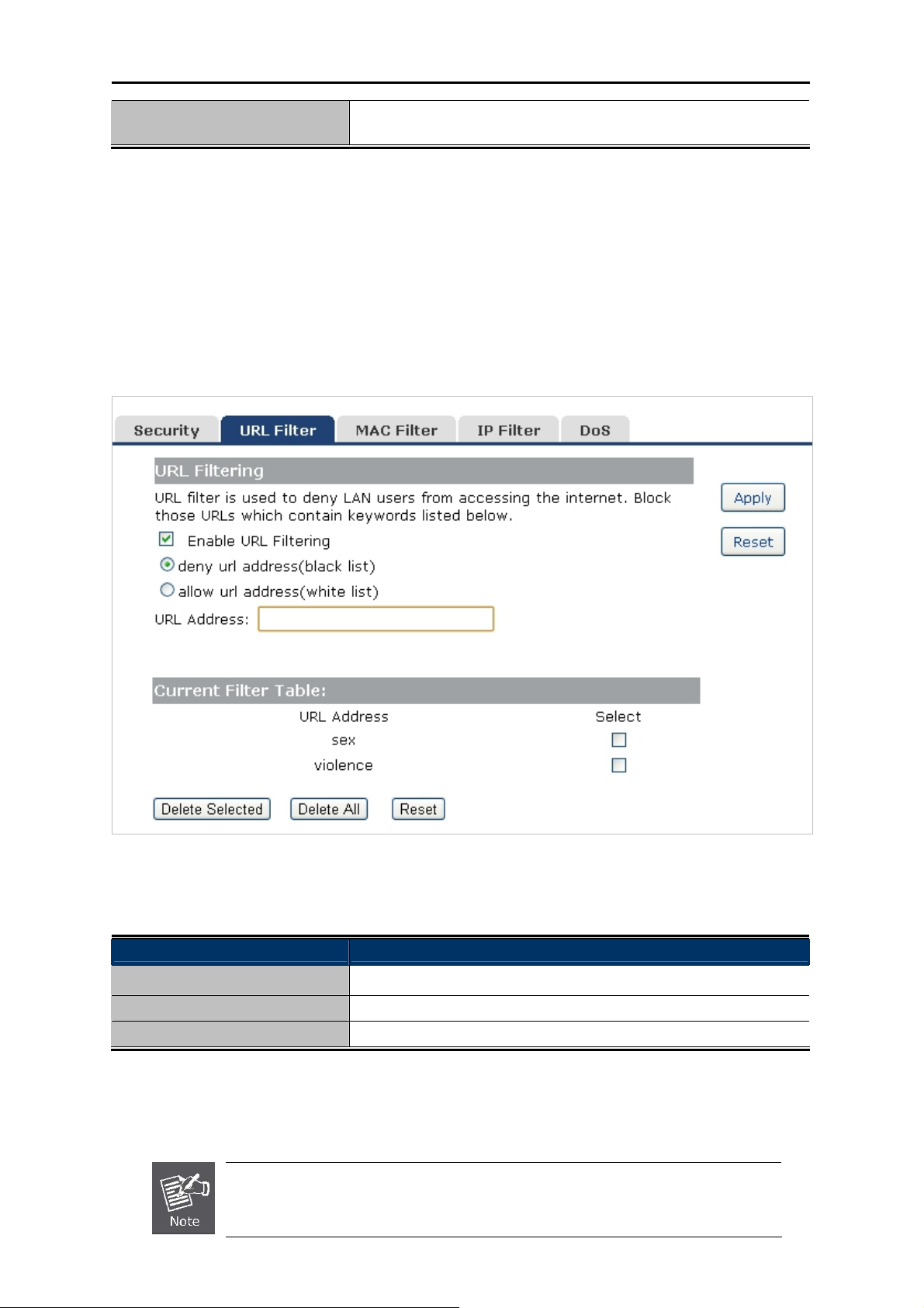
User’s Manual of WNRT-633
Enable IPv6 pass through on
VPN connection
Check the box to enable IPv6 pass through function on VPN
connection.
5.7.2 URL Filtering
URL filter is used to deny LAN users from accessing the internet. Block those URLs which contain
keywords listed below.
Choose menu “Security Setup URL Filtering”, and you can configure which URL addresses to be
blocked. After the configuration, please click the “Apply” button to save the settings.
Figure 5-7-3 URL Filtering
The page includes the following fields:
Object Description
Enable URL Filtering: Check this box to enable URL Filter function.
IP Address: The IP Address that you want to filter.
URL Address: The URL Address that you want to filter.
Check the “Select” box of which rule you want to delete, and then click the “Delete Selected” button to
delete it.
If you wish to block www.facebook.com, simply type in "facebook" and the
Wireless Router will block all websites with the text "facebook" in the URL.
-72-
Page 80

User’s Manual of WNRT-633
5.7.3 MAC Filtering
Entries in this table are used to restrict certain types of data packets from your local network to Internet
through the Wireless Router. Use of such filters can be helpful in securing or restricting your local
network.
Choose menu “Security Setup MAC Filter”, and you can configure which computer of the specified
MAC address to be restricted. After the configuration, please click the “Apply” button to save the
settings.
Figure 5-7-4 MAC Filtering
The page includes the following fields:
Object Description
Enable MAC Filtering Enable MAC filtering
MAC Address Add MAC address you want to control
Comment The description of this setting
Check the “Select” box of which rule you want to delete, and then click the “Delete Selected” button
to delete it.
5.7.4 IP Filtering
IP Filtering is used to block internet or network access to specific IP addresses on your local network.
The restricted user may still be able to login to the network but will not be able to access the internet.
To begin blocking access to an IP address, enable IP Filtering and enter the IP address of the user you
wish to block.
-73-
Page 81
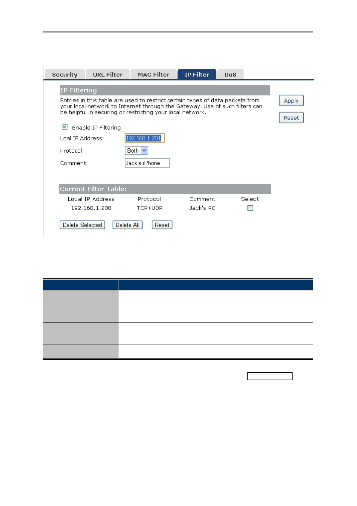
User’s Manual of WNRT-633
Choose menu “Security Setup IP Filter”, and you can configure which IP address and protocol to
be restricted. After the configuration, please click the “Apply” button to save the settings.
Figure 5-7-5 IP Filtering
The page includes the following fields:
Object Description
Enable IP Filtering
Local IP Address
Protocol
Check this box to enable IP Filter function
Add LAN IP address you want to control
Select the port number protocol type (TCP, UDP or both).
If you are unsure, then leave it to the default both protocol
Comment
The description of this setting
Check the “Select” box of which rule you want to delete, and then click the “Delete Selected” button
to delete it.
5.7.5 Denial of Service (DoS)
The Wireless Router can prevent specific DoS attacks from entering your network. A
"Denial-of-Service" (DoS) attack is characterized by an explicit attempt by hackers to prevent
legitimate users of a service from using that service.
-74-
Page 82

User’s Manual of WNRT-633
Choose menu “Security Setup DoS” to configure the settings of DoS attack prevention. After the
configuration, please click the “Apply” button to save the settings.
Figure 5-7-6 Denial of Service
The page includes the following fields:
Object Description
Enable DoS
Prevention
Check to enable DoS function.
User may set other related configurations about DoS below
-75-
Page 83

User’s Manual of WNRT-633
5.8 Route Setup
Static routing is a special type of routing that can be applied in a network to reduce the problem of
routing selection and data flow overload caused by routing selection so as to improve the packets
forwarding speed. You can set the destination IP address, subnet mask, and gateway to specify a
routing rule. The destination IP address and subnet mask determine a destination network or host to
which the router sends packets through the gateway.
5.8.1 Router Setup
A static route is a pre-determined pathway that network information must travel to reach a specific host
or network.
The page includes the following fields:
Object Description
Enable Static Route
IP Address
Click this box to enable static route.
The network or host IP address desired to access.
Figure 5-8-1 Routing Setup
-76-
Page 84

User’s Manual of WNRT-633
Subnet Mask
Gateway
The subnet mask of destination IP.
The gateway is the router or host’s IP address to which packet was
sent. It must be the same network segment with the WAN or LAN port.
Show Routing Table
Static Routing table
Clicking this button will show you all the routing table of the system.
It only shows the static routing table and you can delete one or all.
5.8.2 RIP Setup
The page is used to set up dynamic routing protocol or edit static route entry. After the configuration,
please click the “Apply” button to save the settings.
The page includes the following fields:
Object Description
Enable Dynamic
Click this box to enable Dynamic Route.
Route
Figure 5-8-2 RIP Setup
-77-
Page 85
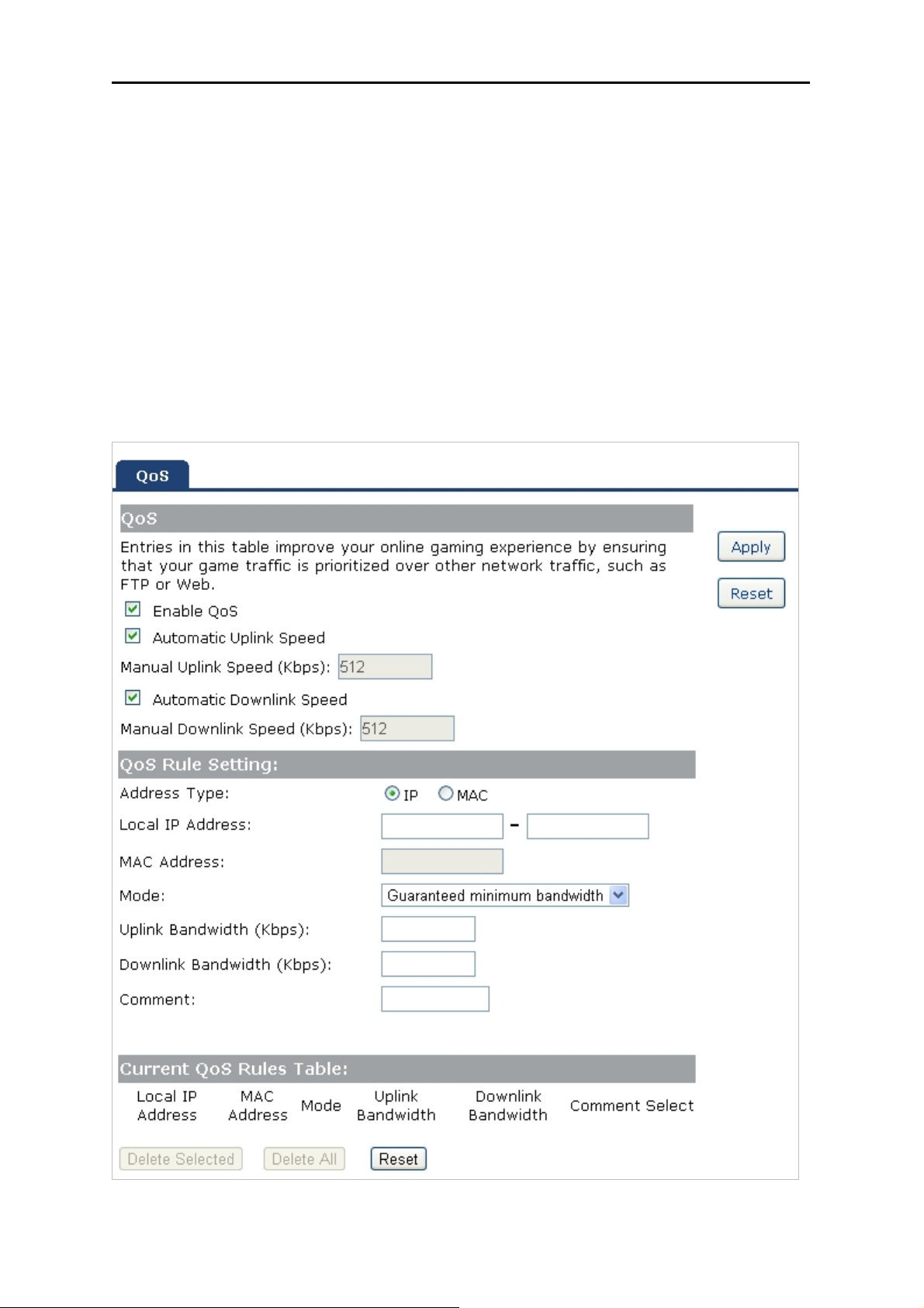
User’s Manual of WNRT-633
5.9 QoS Setup
The QoS (Quality of Service) helps improve your network gaming performance by prioritizing
applications. By default the bandwidth control are disabled and application priority is not classified
automatically. In order to complete this settings, please follow the steps below.
1. Enable this function.
2. Enter the total speed or choose automatic mode.
3. Enter the IP address or MAC address user want to control.
4. Specify how to control this PC with this IP address or MAC address, including maximum or
minimum bandwidth, priority and its up/down speed.
After the configuration, please click the “Apply” button to save the settings.
Figure 5-9-1 QoS
-78-
Page 86

The page includes the following fields:
Object Description
User’s Manual of WNRT-633
Enable QoS
Automatic Uplink Speed
Automatic Downlink
Speed
QoS Rule Setting
5.10 System
Check the box to enable the QoS function.
Check the box to adjust the uplink speed automatically by the
WNRT-633. Or enter the uplink data rate manually in the field below.
Check the box to adjust the downlink speed automatically by the
WNRT-633. Or enter the downlink data rate manually in the field
below.
To set the priority rule, you can appoint the computer by IP address
or MAC address, and enter it in the correct field. Select minimum or
maximum bandwidth, and then fill the uplink and downlink data
rate into the field.
The System menu contains submenus of the general settings of the WNRT-633. Please refer to the
following sections for the details.
Figure 5-10-1
-79-
Page 87

User’s Manual of WNRT-633
5.10.1 Time Zone Setting
This section assists you in setting the Wireless Router’s system time. You can either select to set the
time and date manually or automatically obtain the GMT time from Internet.
Choose menu “System Time Zone Setting” to configure the system time. You can also maintain
the system time by synchronizing with a public time server over the Internet. After the configuration,
please click the “Apply” button to save the settings.
Figure 5-10-2 Time Zone Setting
The page includes the following fields:
Object Description
Time Zone Select
Time Zone Select
Input current time manually.
Select the time zone of the country you are currently in. The router will
set its time based on your selection.
Enable NTP client
update
NTP Server
Check to enable NTP update. Once this function is enabled, Router will
automatically update current time from NTP server.
User may select prefer NTP sever or input address of NTP server
manually.
The configured time and date settings are lost when the Wireless Router is
powered off.
-80-
Page 88

User’s Manual of WNRT-633
5.10.2 Upgrade Firmware
Firmware upgrade is released periodically to improve the functionality of your device and also to add
new features. If you run into a problem with a specific feature of the device, log on to our website
www.planet.com.tw
to download the latest firmware to update your device.
Choose menu “System Upgrade Firmware” to upgrade the firmware of the WNRT-633. Select the
new firmware file downloaded from the PLANET website, and then click “Upload” button to upgrade it.
Figure 5-10-3 Upgrade Firmware
The page includes the following fields:
Object Description
Select File
Browse and select file you want to upgrade and press Upload to perform
upgrade.
Please wait till on screen shows related information after upgrade
is finished.
Do not disconnect the Wireless Router from your management PC (the PC you use
to configure the device) or power off it during the upgrade process; otherwise, it may
be permanently damaged. The Wireless Router will restart automatically when the
upgrade process, which takes several minutes, completes.
5.10.3 Save/Reload Settings
Choose menu “System Save/Reload Settings” to back up or reset the configuration of the
WNRT-633.
Once you have configured the Wireless Router the way you want it, you can save these settings to a
configuration file on your local hard drive that can later be imported to your Wireless Router in case the
device is restored to factory default settings.
-81-
Page 89
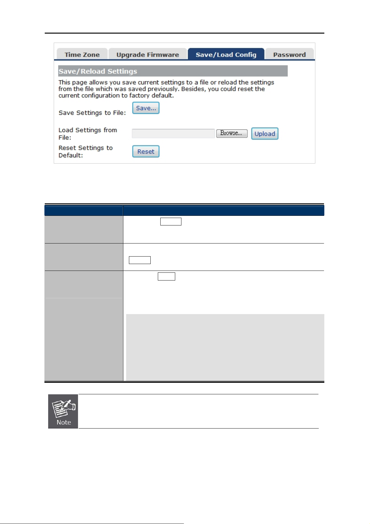
Figure 5-10-4 Save/Reload Settings
The page includes the following fields:
User’s Manual of WNRT-633
Object Description
Save Settings to File Click the “Save…” button to back up the configuration of the
WNRT-633. And then save the “config.dat” in your computer.
Load Settings from File
Select the configuration file of the WNRT-633, and then click the
“Upload” button to reload the configuration back into the WNRT-633.
Reset Settings to
Default
Click the “Reset” button to reset all settings of the WNRT-633 to
factory default.
Factory Default Settings:
User Name: admin
Password: admin
IP Address: 192.168.1.1
Subnet Mask: 255.255.255.0
SSID: WNRT-633
Wireless Security: None
To activate your settings, you need to reboot the Wireless Router after you reset it.
-82-
Page 90
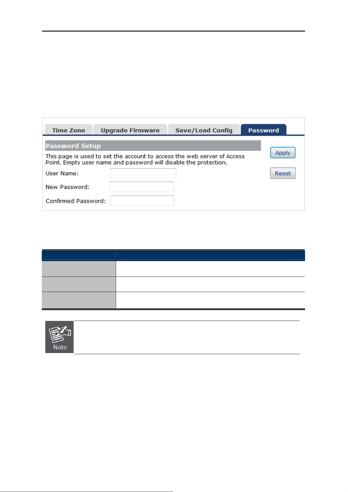
User’s Manual of WNRT-633
5.10.4 Password
To ensure the Wireless Router’s security, you will be asked for your password when you access the
Wireless Router’s Web-based Utility. The default user name and password is “admin”. This page will
allow you to add or modify the user name and passwords.
Choose menu “System Password” to change the user name and password which is inputted to
access the web UI of the WNRT-633.
Figure 5-10-5 Password Setup
The page includes the following fields:
Object Description
User Name
New Password
Confirmed Password
Enter user name.
Input password for this user.
Confirm password again.
For the sake of security, it is highly recommended that you change default login
password and user name.
-83-
Page 91
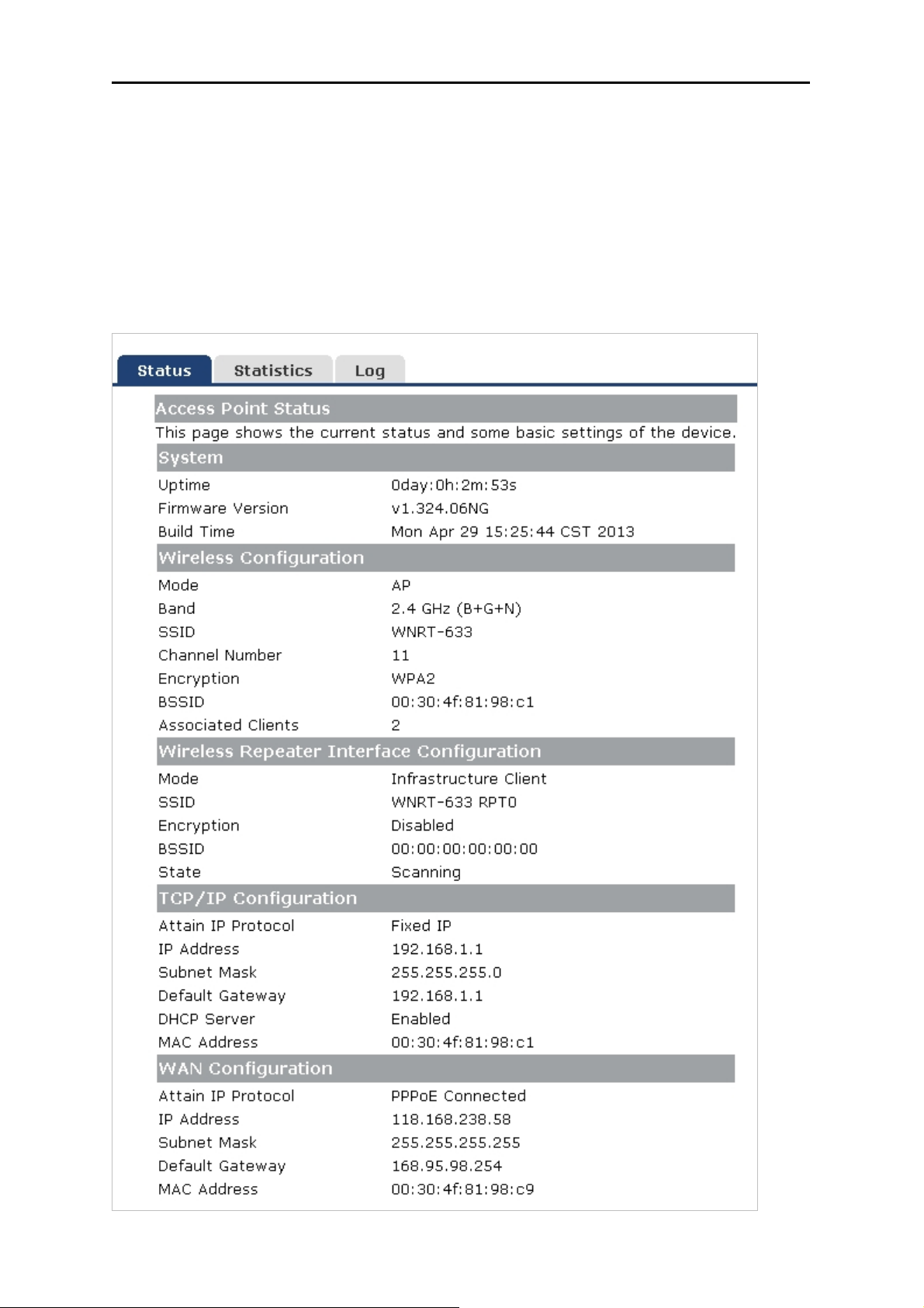
User’s Manual of WNRT-633
5.11 Status
You can use this function to realize the instantaneous information of the Wireless Router. The
Information displayed here may vary on different configurations.
5.11.1 Status
Choose menu “Status Status” to show the current status and some basic settings of the
WNRT-633.
Figure 5-11-1 Status
-84-
Page 92
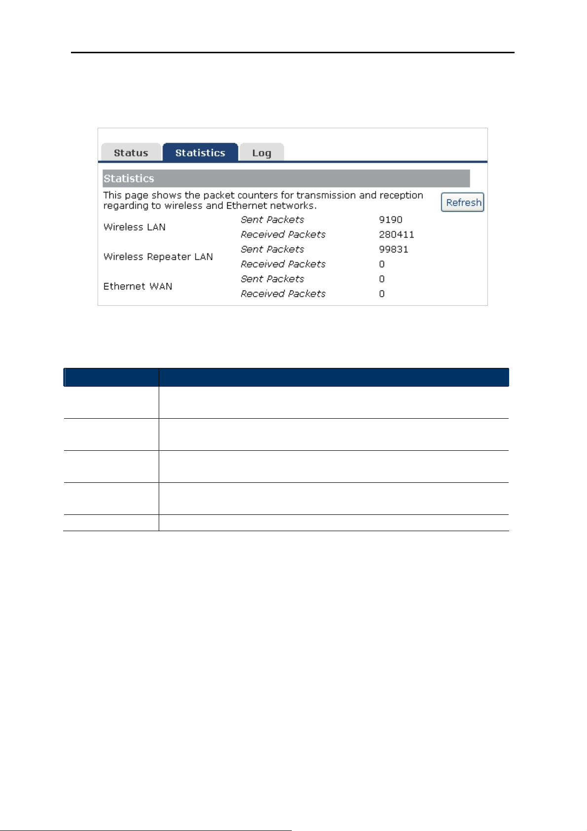
User’s Manual of WNRT-633
5.11.2 Statistics
Choose menu “Status Statistics” to show the packet counters for transmission and reception
regarding wireless and Ethernet network.
Figure 5-11-2 Statistics
The page includes the following fields:
Item Description
Wireless LAN
Sent Packets
Wireless LAN
Received Packets
Ethernet WAN
Sent Packets
Ethernet WAN
Received Packets
Refresh Click the refresh the statistic counters on the screen.
It shows the statistic count of sent packets on the wireless LAN interface.
It shows the statistic count of received packets on the wireless LAN interface.
It shows the statistic count of sent packets on the Ethernet WAN interface.
It shows the statistic count of received packets on the Ethernet WAN
interface.
5.11.3 Log
Choose menu “Management Log” to configure the settings of system log. You can check the box of
the items you want to record it in the log. After the configuration, please click the “Apply” button to save
the settings.
-85-
Page 93
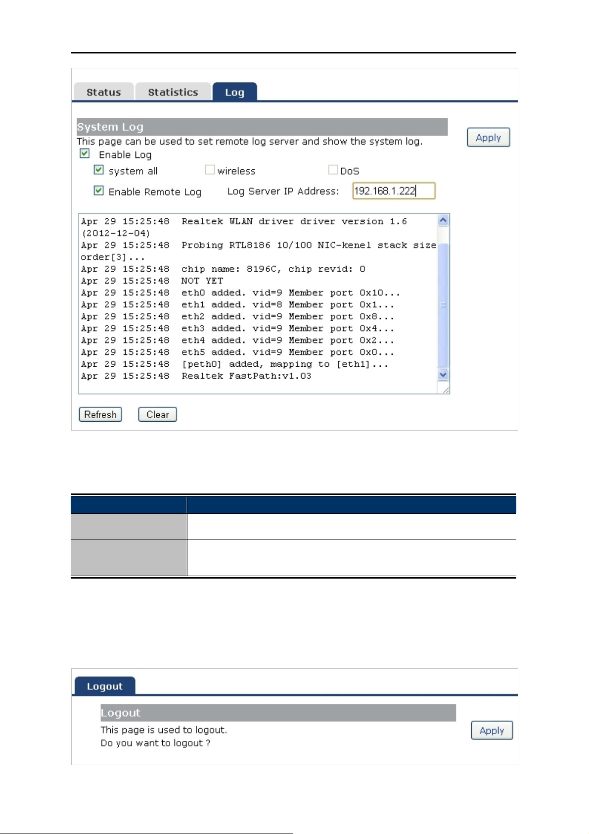
User’s Manual of WNRT-633
Figure 5-11-3 System Log
The page includes the following fields:
Object Description
Enable Log
System all/Dos
Check to enable log function.
Select which log you want to check. Related information will be shown
below.
5.12 Logout
Click “Logout” to log out the web UI of the WNRT-633. And then click the “Apply” button for sure.
Figure 5-12-1 Logout
-86-
Page 94
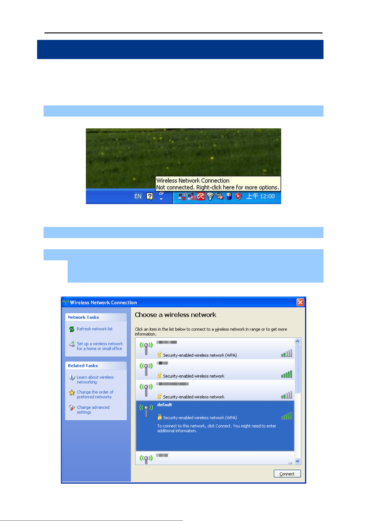
User’s Manual of WNRT-633
Chapter 6. Quick Connection to a Wireless Network
In the following sections, the default SSID of the WNRT-633 is configured to “default”.
6.1 Windows XP (Wireless Zero Configuration)
Step 1: Right-Click on the wireless network icon displayed in the system tray
Figure 6-1-1
Step 2: Select [View Available Wireless Networks]
Step 3: Highlight and select the wireless network (SSID) to connect
(1) Select SSID [default]
(2) Click the [Connect] button
Figure 6-1-2
-87-
Page 95
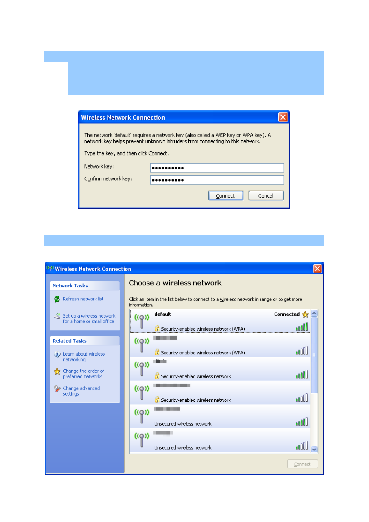
Step 4: Enter the encryption key of the Wireless Router
(1) The Wireless Network Connection box will appear
(2) Enter the encryption key that configured in section 5.5.3
(3) Click the [Connect] button
User’s Manual of WNRT-633
Step 5: Check if “Connected” is displayed
Figure 6-1-3
Figure 6-1-4
-88-
Page 96

User’s Manual of WNRT-633
Some laptops are equipped with a “Wireless ON/OFF” switch for the internal
wireless LAN. Make sure the hardware wireless switch is switch to “ON” position.
6.2 Windows 7 (WLAN AutoConfig)
WLAN AutoConfig service is built-in in Windows 7 that can be used to detect and connect to wireless
network. This built-in wireless network connection tool is similar to wireless zero configuration tool in
Windows XP.
Step 1: Right-Click on the network icon displayed in the system tray
Figure 6-2-1
Step 2: Highlight and select the wireless network (SSID) to connect
(1) Select SSID [default]
(2) Click the [Connect] button
Figure 6-2-2
-89-
Page 97
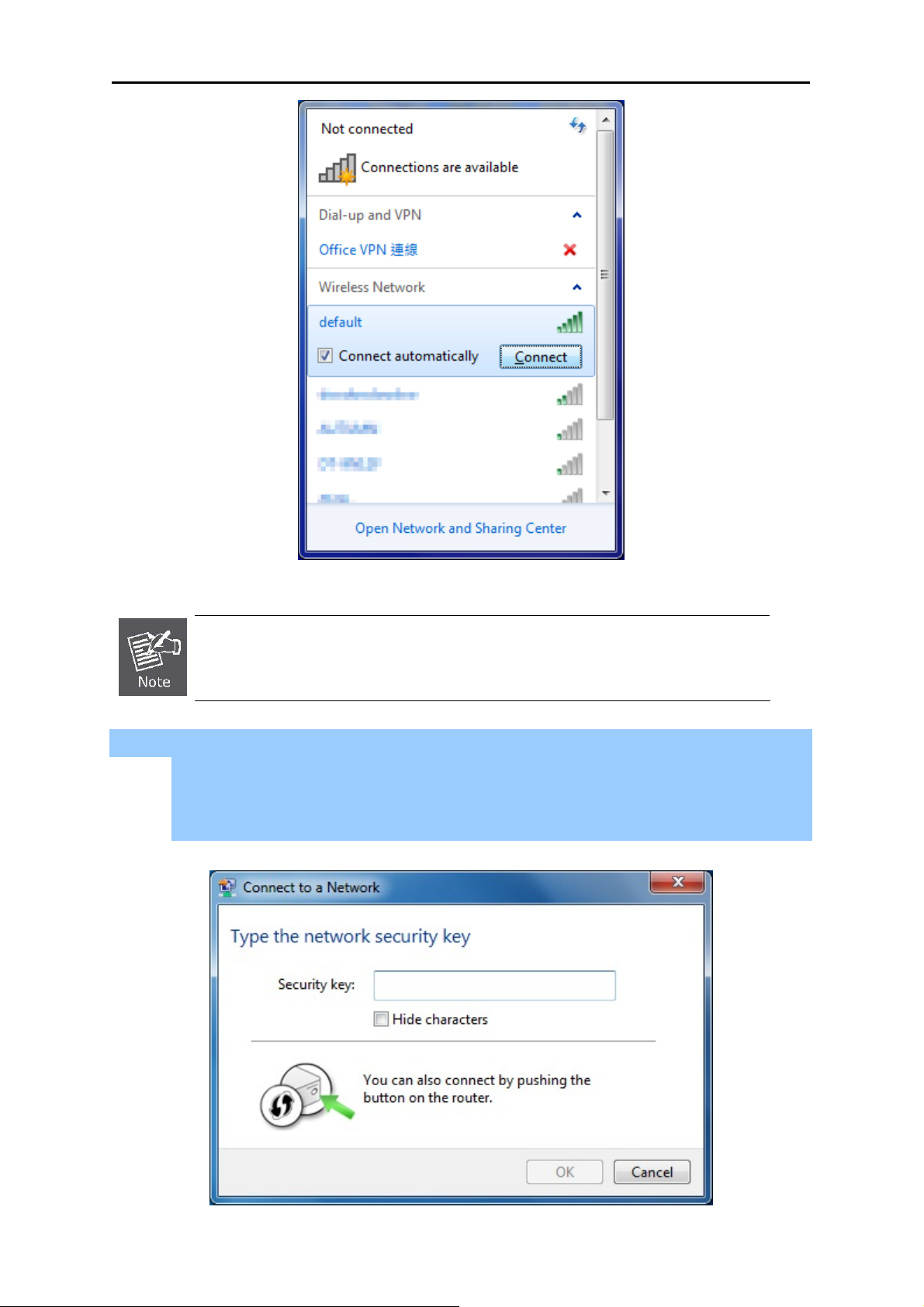
User’s Manual of WNRT-633
Figure 6-2-3
If you will be connecting to this Wireless Router in the future, check [Connect
automatically].
Step 4: Enter the encryption key of the Wireless Router
(1) The Connection to a Network box will appear
(2) Enter the encryption key that is configured in section 5.5.3
(3) Click the [OK] button
Figure 6-2-4
-90-
Page 98

Step 5: Check if “Connected” is displayed
User’s Manual of WNRT-633
Figure 6-2-5
Figure 6-2-6
-91-
Page 99

User’s Manual of WNRT-633
6.3 Mac OS X 10.x .3 Mac OS X 10.x
In the following sections, the default SSID of the WNRT-633 is configured to “default”. In the following sections, the default SSID of the WNRT-633 is configured to “default”.
Step 1: Right-Click on the network icon displayed in the system tray
The AirPort Network Connection menu will appear
Figure 6-3-1
Step 2: Highlight and select the wireless network (SSID) to connect
(1) Select and SSID [default]
(2) Double-click on the selected SSID
Figure 6-3-2
Step 4: Enter the encryption key of the Wireless Router
(4) Enter the encryption key that is configured in section 5.5.3
(1) Click the [OK] button
-92-
Page 100
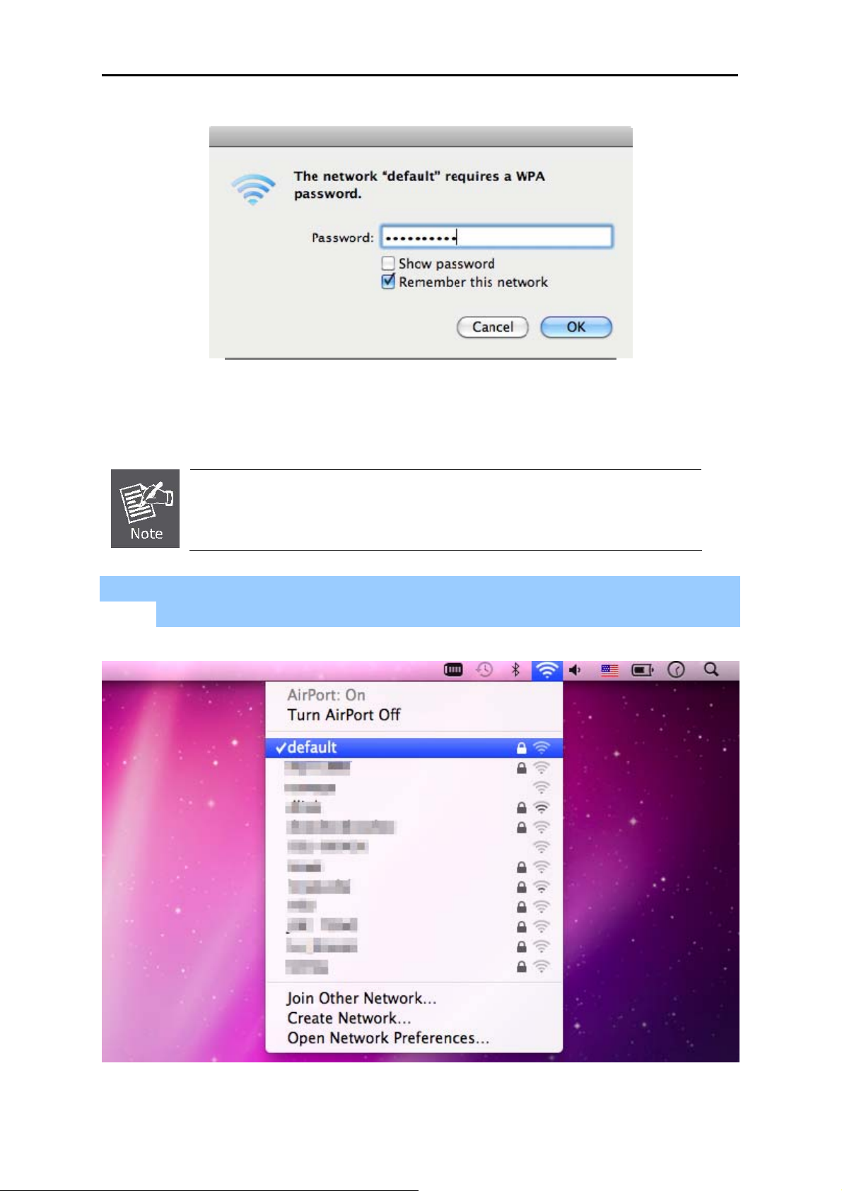
User’s Manual of WNRT-633
Figure 6-3-3
If you want to connect this Wireless Router in the future, check [Remember this
network].
Step 5: Check if the AirPort is connected to the selected wireless network.
If “Yes”, then there will be a “check” symbol in the front of the SSID.
Figure 6-3-4
-93-
 Loading...