

Page 1

802.11n Wireless Broadband Router
WNRT-625
User’s Manual
Page 2

Copyright
Copyright © 2009 by PLANET Technology Corp. All rights reserved. No part of this publication may be reproduced,
transmitted, transcribed, stored in a retrieval system, or translated into any language or computer language, in any
form or by any means, electronic, mechanical, magnetic, optical, chemical, manual or otherwise, without the prior
written permission of PLANET.
PLANET makes no representations or warranties, either expressed or implied, with respect to the contents hereof and
specifically disclaims any warranties, merchantability or fitness for any particular purpose. Any software described in
this manual is sold or licensed "as is". Should the programs prove defective following their purchase, the buyer (and not
this company, its distributor, or its dealer) assumes the entire cost of all necessary servicing, repair, and any incidental
or consequential damages resulting from any defect in the software. Further, this company reserves the right to revise
this publication and to make changes from time to time in the contents hereof without obligation to notify any person of
such revision or changes.
All brand and product names mentioned in this manual are trademarks and/or registered trademarks of their respective
holders.
Federal Communication Commission Interference Statement
This equipment has been tested and found to comply with the limits for a Class B digital device, pursuant to Part 15 of
FCC Rules. These limits are designed to provide reasonable protection against harmful interference in a residential
installation. This equipment generates, uses, and can radiate radio frequency energy and, if not installed and used in
accordance with the instructions, may cause harmful interference to radio communications. However, there is no
guarantee that interference will not occur in a particular installation. If this equipment does cause harmful interference
to radio or television reception, which can be determined by turning the equipment off and on, the user is encouraged
to try to correct the interference by one or more of the following measures:
1. Reorient or relocate the receiving antenna.
2. Increase the separation between the equipment and receiver.
3. Connect the equipment into an outlet on a circuit different from that to which the receiver is
connected.
4. Consult the dealer or an experienced radio technician for help.
FCC Caution:
To assure continued compliance, (example-use only shielded interface cables when connecting to computer or
peripheral devices) any changes or modifications not expressly approved by the party responsible for compliance could
void the user’s authority to operate the equipment.
2
Page 3

This device complies with Part 15 of the FCC Rules. Operation is subject to the Following two conditions: (1) This
device may not cause harmful interference, and (2) this Device must accept any interference received, including
interference that may cause undesired operation.
Federal Communication Commission (FCC) Radiation Exposure Statement
This equipment complies with FCC radiation exposure set forth for an uncontrolled environment. In order to avoid the
possibility of exceeding the FCC radio frequency exposure limits, human proximity to the antenna shall not be less than
20 cm (8 inches) during normal operation.
R&TTE Compliance Statement
This equipment complies with all the requirements of DIRECTIVE 1999/5/CE OF THE EUROPEAN PARLIAMENT
AND THE COUNCIL OF 9 March 1999 on radio equipment and telecommunication terminal Equipment and the mutual
recognition of their conformity (R&TTE).
The R&TTE Directive repeals and replaces in the directive 98/13/EEC (Telecommunications Terminal Equipment and
Satellite Earth Station Equipment) As of April 8, 2000.
Safety
This equipment is designed with the utmost care for the safety of those who install and use it. However, special
attention must be paid to the dangers of electric shock and static electricity when working with electrical equipment. All
guidelines of this and of the computer manufacture must therefore be allowed at all times to ensure the safe use of the
equipment.
WEEE regulation
To avoid the potential effects on the environment and human health as a result of the presence of hazardous
substances in electrical and electronic equipment, end users of electrical and electronic equipment should
understand the meaning of the crossed-out wheeled bin symbol. Do not dispose of WEEE as unsorted
municipal waste and have to collect such WEEE separately.
Revision
User’s Manual for PLANET 802.11N Wireless Router
Model: WNRT-625v3
Rev: 1.1 (December. 2009)
3
Page 4

TABLE OF CONTENTS
CHAPTER 1 INTRODUCTION ..................................................................................................................................... 6
1.1
P
ACKAGE CONTENTS
1.2
F
EATURES
1.3
S
PECIFICATION
CHAPTER 2 HARDWARE INSTALLATION / NETWORK SETUP ........................................................................8
2.1
H
ARDWARE INSTALLATION
2.2
LED I
2.3
N
ETWORK SETUP
CHAPTER 3 INTRODUCTION TO WEB CONFIGURATION ............................................................................... 14
3.1
WEB LOGIN
3.2
OPERATION MODE
3.3
INTERNET SETTINGS
3.3.1 WAN.......................................................................................................................................................... 15
3.3.2 LAN .......................................................................................................................................................... 21
3.3.3 DHCP clients............................................................................................................................................. 22
......................................................................................................................................................... 6
NDICATORS
........................................................................................................................................................ 14
........................................................................................................................................ 6
.................................................................................................................................................. 6
............................................................................................................................... 8
............................................................................................................................................ 11
............................................................................................................................................ 12
.............................................................................................................................................. 14
........................................................................................................................................... 15
3.3.4 Advanced Routing..................................................................................................................................... 23
3.3.5 QoS............................................................................................................................................................ 24
CHAPTER 4 WIRELESS SETTINGS ......................................................................................................................... 25
4.1
BASIC
4.2
ADVANCED WIRELESS SETTINGS
4.3
SECURITY
4.4
4.5
STATI ON L IST
CHAPTER 5 FIREWALL ............................................................................................................................................. 33
5.1
5.2
PORT FORWARDING
5.3
5.4
SYSTEM SECURITY SETTINGS
5.5
CONTENT FILTERING
CHAPTER 6 ADMINISTRATION ............................................................................................................................... 38
................................................................................................................................................................. 25
........................................................................................................................ 28
........................................................................................................................................................... 30
WPS................................................................................................................................................................... 31
...................................................................................................................................................... 32
MAC/IP/P
DMZ .................................................................................................................................................................. 35
ORT FILTERING
............................................................................................................................................ 34
.......................................................................................................................................... 37
.................................................................................................................................. 33
............................................................................................................................. 36
6.1
MANAGEMENT
6.2
MANAGEMENT UPLOAD FIRMWARE
6.3
SETTING MANAGEMENT
................................................................................................................................................... 38
................................................................................................................... 39
..................................................................................................................................... 39
4
Page 5

STATU S
6.4
6.5
STATI ST IC
6.6
SYSTEM LOG
............................................................................................................................................................... 40
........................................................................................................................................................... 41
...................................................................................................................................................... 42
5
Page 6
Chapter 1 Introduction
Thank you for purchasing WNRT-625. This manual guides you on how to install and properly use the
WNRT-625 in order to take full advantage of its features.
1.1 Package Contents
Make sure that you have the following items:
•
WNRT-625 x 1
•
Ethernet Cable x 1
•
Power Adapter x 1
•
CD-ROM (included user’s manual) x 1
•
Quick Installation Guide x 1
If any of the above items are missing, please contact your supplier for support
1.2 Features
z IEEE 802.11n wireless technology compliant with 802.11b/g standard
z Capable of up to 300Mbps data rate
z Supports Wi-Fi Protected Setup (WPS)
z Supports 64/128-bit WEP, WPA –TKIP(PSK), WPA2-AES(PSK), 802.1x
z AP / Station-Infrastructure / Bridge (WDS) / Repeater modes supported
z Equipped with four LAN ports (10/100M) and one WAN port (10/100M), Auto-MDI/MDI-X
supported
z Supports DHCP Server
z System status monitoring includes Active DHCP Client, Security Log and Device/Connection
Status
z Web-based GUI for and Wizard setup for easily configuration
z Remote Management allows configuration and upgrades from a remote site
z Supported Internet types: Dynamic / Static IP / PPPoE / PPTP / L2TP
z MAC / IP filter access control, URL blocking ; SPI firewall + DoS prevention protection
z Supports UPnP function
1.3 Specification
Standard IEEE 802.11b/g, 802.11n Draft 2.0, IEEE802.3u
Frequency range 2.4 ~ 2.4835GHz
IEEE 802.11b: DQPSK, DBPSK, DSSS, and CCK
Radio Technology
WAN Port 1 x 100Base-TX, Auto-MDI/MDI-X
LAN Port 4 x 100Base-TX, Auto-MDI/MDI-X
Antenna connector 2 x Fixed 2dBi Dipole Antenna
Data Encryption
Frequency 2.400GHz - 2.483GHz
Output Power
IEEE 802.11 g: BPSK, QPSK, 16QAM, 64QAM
IEEE 802.11n: MCS0~MCS7
64 bit / 128 bit WEP, WPA-PSK, WPA, WPA2, 802.1x encryption
802.11b: Typ. 18dBm@Normal Temp Range;
802.11g: Typ. 15dBm@Normal Temp Range;
802.11n: Typ. 15dBm@Normal Temp Range.
6
Page 7

7
Data Rate
Receiver Sensitivity
Session 3000
LED Indicators
11Mbps Max @802.11b
54Mbps Max @802.11g
300Mbps Max @802.11n
1 Mbps:-94 dBm,
2 Mbps:-91 dBm,
5.5 Mbps:-89 dBm,
11 Mbps:-85 dBm;
6 Mbps:-90 dBm,
9 Mbps:-89 dBm;
12 Mbps:-86 dBm,
18 Mbps:-84 dBm;
24 Mbps:-81 dBm,
36 Mbps:-77 dBm;
48 Mbps:-73 dBm,
54 Mbps:-72 dBm,
300Mbps:-68dBm
PWR, WLAN, WPS, WAN * 1, LAN * 4
Page 8

Chapter 2 Hardware Installation / Network Setup
Please follow the below instruction to build the wireless network connection between WNRT-625 and your
computers.
2.1 Hardware Installation
Interface Function
Resets to the factory defaults. To restore factory defaults, keep the device powered on
Reset
ON/OFF
Power
WAN
LAN 1~4
WPS
1. Locate an optimum location for the WNRT-625. Th e best place for your WNRT-625 is usually at
the center of your wireless network, with line of sight to all of your mobile stations.
2. Adjust the antennas of WNRT-625. Try to adjust them to a position that can best cover your wireless
network. The antenna’s position will enhance the receiving sensitivity.
and push a paper clip into the hole. Press down the button over 5 seconds and then
release.
Power on or off.
Interface that connects to the power adapter. 12 V DC, 500mA
Ethernet RJ-45 interfaces that connect to the Internet.
Ethernet RJ-45 interfaces that connect to the Ethernet interface of the computer or
Ethernet devices.
WPS on or off switch.
8
Page 9
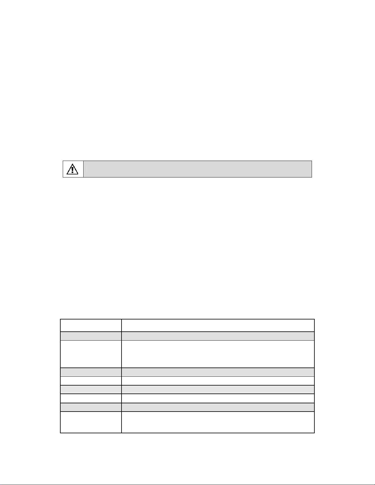
3. Connect xDSL/Cable Modem to WAN port of WNRT-625. Usually, this cable would be provided with
your modem. If no cable was supplied with your modem, please use a RJ-45 Ethernet cable
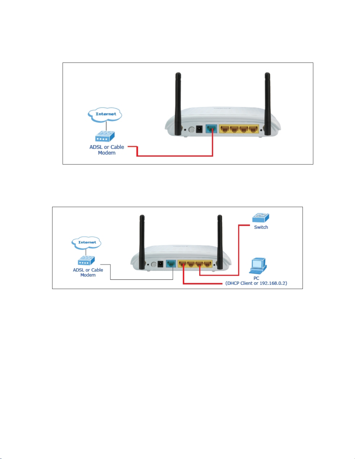
4. Connect all of your network devices to LAN port of WNRT-625. Connect all your computers,
network devices (network-enabled consumer devices other than computers, like game console, or
switch / hub).Connect one of the LAN ports on WNRT-625 to your LAN switch/hub or a computer with
a RJ-45 cable.
9
Page 10
0
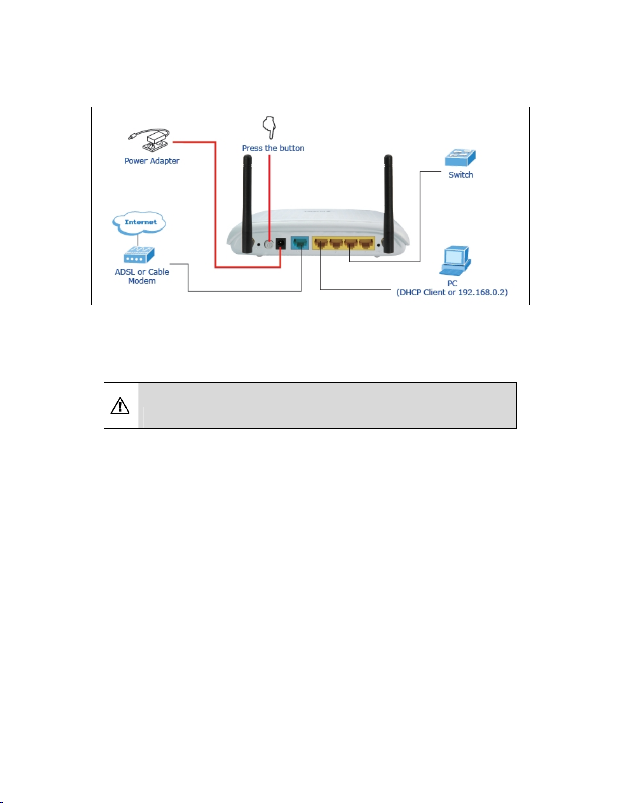
5. Plug in power adapter and connect to power source, then press ON/OFF button. After power on,
WNRT-625 will start to operate.
6. Please check all LEDs on the front panel. ‘PWR’ LED should be steadily on. WAN and LAN LEDs
should be on if the computer / network device connected to the respective port of the router is powered
on and correctly connected. If PWD LED is not on, or any LED you expected is not on, please recheck
the cabling, or jump to ‘Troubleshooting’ for possible reasons and solution.
1. ONLY use the power adapter supplied with the WNRT-625. Otherwise, the product may
be damaged.
2. If you want to reset WNRT-625 to default settings, press and hold the Reset button over
5 seconds and release. And then wait for WNRT-625 restart.
1
Page 11
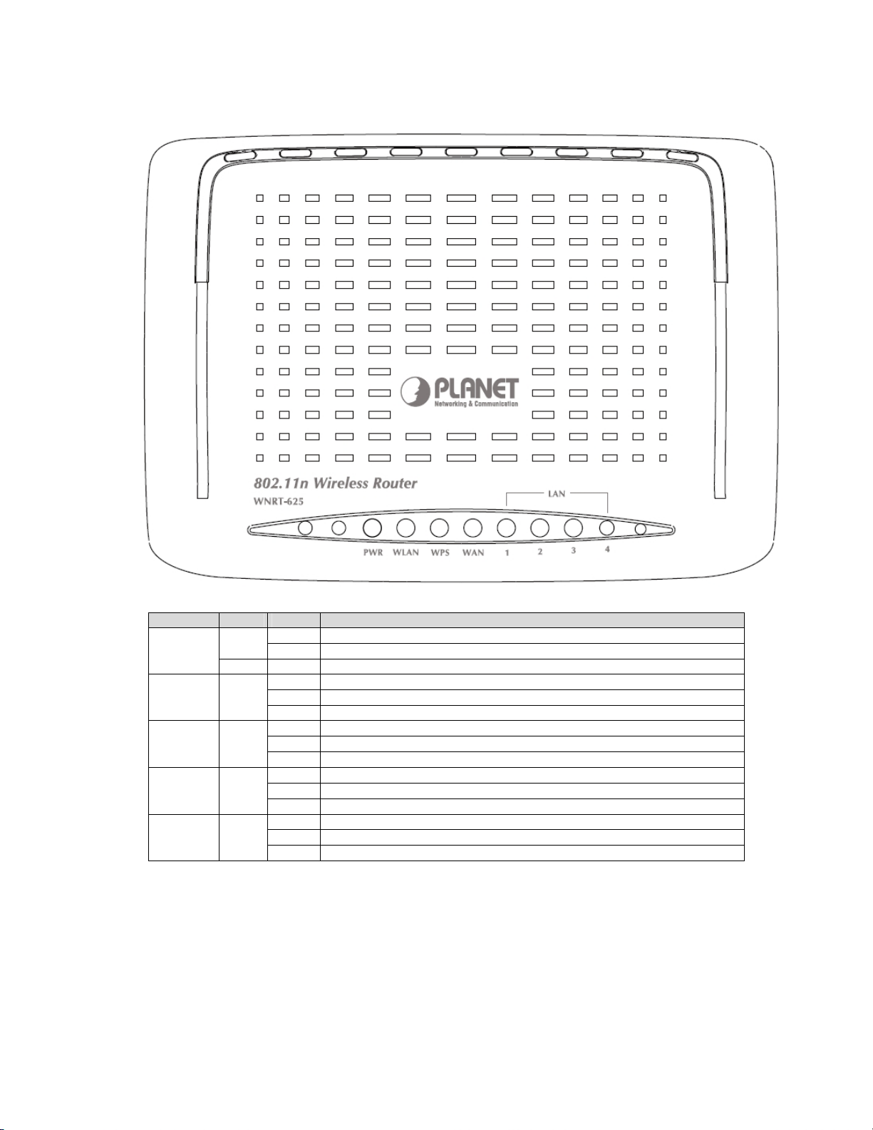
2.2 LED Indicators
LEDs Color Status Description
PWR
WLAN Green
WPS Green
WAN Green
LAN 1~4 Green
Green
Red On The device is power on and initializing.
On The device is powered on, and it is running normally.
Off The device is powered off.
On WLAN radio is on.
Blinks Data is being transmitted through WLAN.
Off WLAN radio is off.
On WPS client registration is successful.
Blinks WPS client registration window is currently open.
Off WPS is not available, or WPS is not enabled or initialized.
On
Blinks The device is receiving or sending data on WAN.
Off The WAN is not connected.
On The device has successful Ethernet connections.
Blinks The device is receiving or sending data on LAN.
Off The LAN is not connected.
The device has successful Ethernet connections.
11
Page 12
2
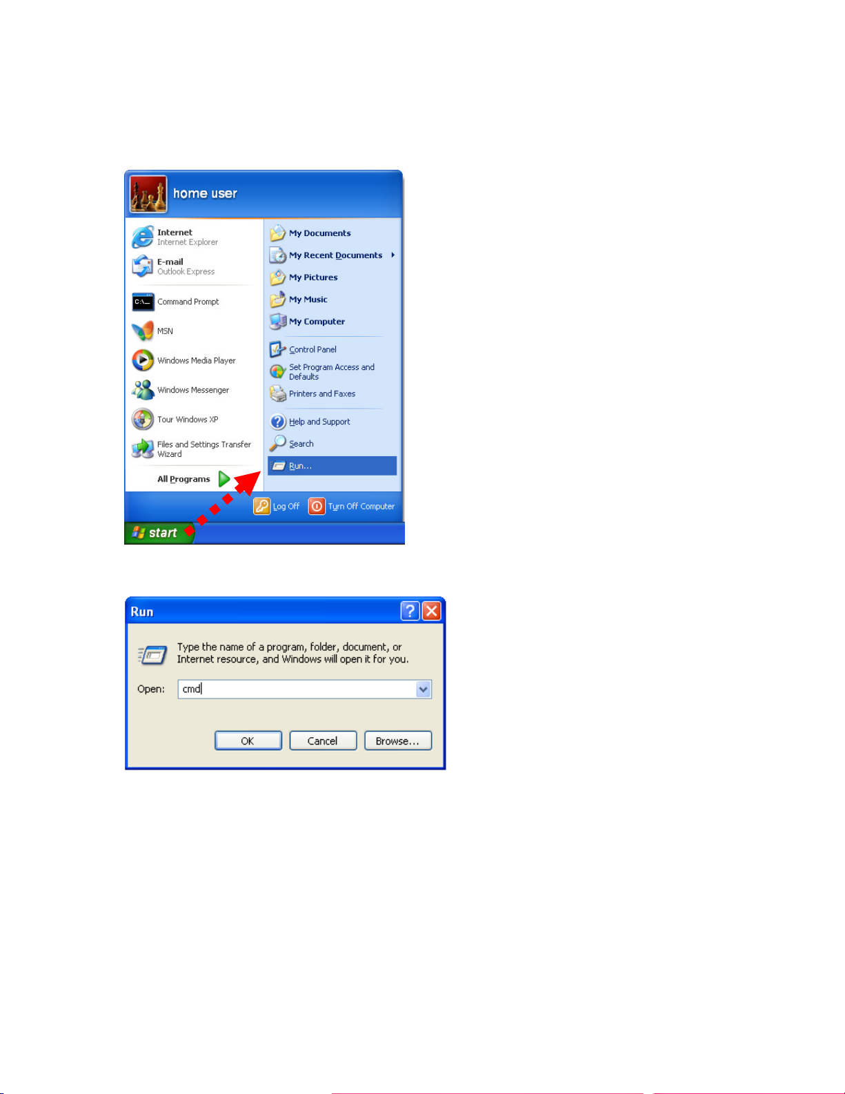
2.3 Network Setup
After you install your WNRT-625, the TCP/IP settings should be set to obtain an IP address from a DHCP
server (WNRT-625) automatically. To verify your IP address, please follow the steps below:
1. Click on Start > Run.
2. In the run box type “cmd” and click OK. (Windows VistaR users type cmd in the Start .Search box.)At the
prompt.
1
Page 13
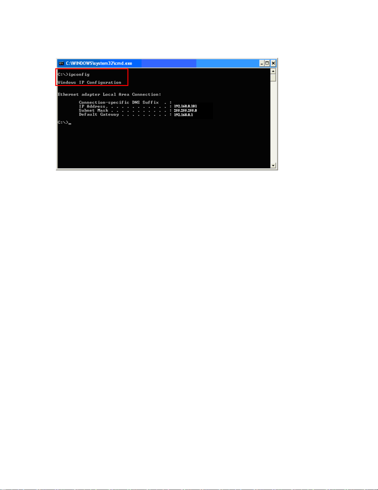
3. Type “ipconfig” and press Enter. It will display the IP address, subnet mask, and the default gateway of
adapter.
4. If the address is 0.0.0.0, check your adapter installation, security settings, and the settings on your router.
Some firewall software programs may block a DHCP request on newly installed adapters.
Assign a static IP address
If you are not using a DHCP capable gateway/router, or you need to assign a static IP address, please follow
the steps below:
1. - Windows Vista® - Click on Start > Control .Panel > Network .and .Internet
>Network .and .Sharing .Center > Manage Network Connections.
- Windows® XP - Click on Start > Control .Panel > Network Connections.
- Windows® 2000 - From the desktop, right-click My Network Places > Properties.
2. Right-click on the Local Area Connection which represents your network adapter and select Properties.
3. Highlight Internet .Protocol .(TCP/IP) and click Properties.
4. Click Use .the .following .IP .address and enter an IP address that is on the same subnet as your
network or the LAN IP address on your router.
Example: If LAN IP address of WNRT-625 is 192.168.0.1, make your IP address 192.168.0.X where X
is a number between 2 and 99. Make sure that the number you choose is not in use on the network. Set
Default Gateway the same as the LAN IP address of your router (192.168.0.1).
Set Primary DNS the same as the LAN IP address of your router (192.168.0.1). The Secondary DNS is
not needed or you may enter a DNS server from your ISP.
5. Click OK twice to save your settings.
13
Page 14

Chapter 3 Introduction to Web Configuration
3.1 Web Login
WNRT-625 with an assigned IP address allows you to monitor and configure via web browser (e.g., MS
Internet Explorer or Netscape).
1. Open your web browser.
2. Enter the IP address of your WNRT-625 in the address field (default IP address is
http://192.168.0.1
3. Please enter your User Name and Password in the dialog box, and then click “OK”. Default User
name and password as below:
User Name:
Password:
admin
admin
).
4. Then you will see the WNRT-625 HOME screen as below.
3.2 Operation Mode
Choose
operation mode according to your practice.
¾ Bridge:
¾ Gateway:
Operation Mode
All Ethernet and wireless interfaces are bridged into a single bridge interface.
The first Ethernet interface is treated as WAN interface. The other Ethernet interfaces
and the wireless interface are bridged together treated as LAN interfaces. If the device is in
Gateway operation mode, you can enable or disable NAT. Gateway is the default operation
mode.
and the following page appears. In this page, you can configure the
14
Page 15

5
¾ WISP:
connect to ISP’s Access Point. The NAT is enabled and PCs in Ethernet ports share the same IP
to ISP through wireless LAN. The connection type can be setup in WAN page by using PPPoE,
DHCP client, PPTP/L2TP client or static IP.
All the Ethernet ports are bridged together and the wireless interface of this router will
If you select
available. (Firewall functions on the left page are not available.)
Bridge operation mode
, WAN configuration in Internet Settings are not
After finishing setting, click
Click
Cancel
to close without saving.
Apply
to save the settings and make the new configuration take effect.
3.3 Internet Settings
3.3.1 WAN
The WAN Settings screen allows you to specify the type of Internet connection. The WAN settings offer
the following selections for the router’s WAN port,
(ADSL)
,
L2TP,
and
PPTP
.
STATIC (fixed IP), DHCP (Auto config), PPPoE
1
Page 16

6
¾ STATIC (FIXED IP)
Select
STATIC (fixed IP)
in the
WAN Connection Type
drop-down list and the following page appears.
Static Mode
IP Address:
Subnet Mask:
Default Gateway:
Primary DNS Server:
Enter the IP address of WAN port.
Enter IP subnet mask of WAN port.
Enter the default gateway address of WAN port.
Primary DNS Server f of WAN port.
Secondary DNS Server:
Secondary DNS Server of WAN port.
MAC Clone
MAC Clone
provides WAN to connect to a MAC address.
Enabled:
Enable or disable MAC clone.
After finishing setting, click
Click
Cancel
to close without saving.
Apply
to save the settings and make the new configuration take effect.
1
Page 17

7
¾ DHCP (AUTO CONFIG)
Select
DHCP (Auto config)
appears. If the WAN connection type is set to
gateway and DNS address from the DHCP server on WAN interface.
MAC Clone
in the
WAN Connection Type
DHCP
, the device automatically obtains the IP address,
drop-down list and the following page
MAC Clone
After finishing setting, click
Click
¾ PPPOE (ADSL)
Select
the WAN connection type is set to
PPPoE dial up.
provides WAN to connect to a MAC address.
Enabled:
Cancel
PPPoE (ADSL)
Enable or disable MAC clone.
Apply
to close without saving.
in the
WAN Connection Type
to save the settings and make the new configuration take effect.
drop-down list and the following page appears. If
PPPoE (ADSL)
, you can configure the following parameters to
1
Page 18

PPPoE Mode
User Name:
Password:
Verify Password:
Operation Mode:
Keep Alive
redial period expires, AP will execute dial-up again to keep online.
On Demand
detect the flow of the user continuously, AP automatically stops the PPPOE connection.
Once it detects the flow (e.g., accessing a webpage), the router restarts the PPPOE dial-up.
MAC Clone
Enabled:
After finishing setting, click
Click
Cancel
¾ L2TP
Select
L2TP
two address modes:
User name of PPPoE account
Password of PPPoE account
Enable or disable.
to close without saving.
in the
WAN Connection Type
Static
Enter the password of PPPoE account again.
It provides two types of operation modes.
means keeping on-line mode. You can set the redial period in the field. When the
means executing dial-up on demand. Within the preset idle time, if AP does not
Apply
to save the settings and make the new configuration take effect.
drop-down list and the following page appears. There are
and
Dynamic
.
1. If you select
Static
in the
Address Mode
field, the page shown in the following figure appears.
18
Page 19

2. If you select
L2TP Mode
Server IP:
User Name:
Password:
IP Address:
Subnet Mask:
Default Gateway:
Operation Mode:
Dynamic
in the
Address Mode
field, the page shown in the following figure appears.
Address of L2TP server.
The user name of L2TP account.
The password of L2TP account.
IP address of WAN port.
Subnet mask of WAN port.
The default gate way of WAN port.
It provides two types of operation modes.
Keep Alive
redial period expires, AP will execute dial-up again to keep online.
On Demand
detect the flow of the user continuously, AP automatically stops the PPPOE connection.
Once it detects the flow (e.g., accessing a webpage), the router restarts the PPPOE dial-up.
means keeping on-line mode. You can set the redial period in the field. When the
means executing dial-up on demand. Within the preset idle time, if AP does not
MAC Clone
Enabled:
Enable or disable.
After finishing setting, click
Click
Cancel
to close without saving.
Apply
to save the settings and make the new configuration take effect.
19
Page 20

0
¾ PPTP
Select
PPTP
in the
two address modes:
WAN Connection Type
Static
and
Dynamic
.
drop-down list and the following page appears. There are
PPTP Mode
Server IP:
User Name:
Password:
IP Address:
Subnet Mask:
Default Gateway:
Operation Mode:
Address of PPTP server.
The user name of PPTP account.
The password of PPTP account.
IP address of WAN port.
Subnet mask of WAN port.
Keep Alive
means keeping on-line mode. You can set the redial period in the field. When the
redial period expires, AP will execute dial-up again to keep online.
On Demand
detect the flow of the user continuously, AP automatically stops the PPPOE connection.
Once it detects the flow (e.g., accessing a webpage), the router restarts the PPPOE dial-up.
MAC Clone
Enabled:
Enable or disable.
After finishing setting, click
Click
Cancel
to close without saving.
The default gate way of WAN port.
It provides two types of operation modes.
means executing dial-up on demand. Within the preset idle time, if AP does not
Apply
to save the settings and make the new configuration take effect.
2
Page 21

3.3.2 LAN
This page allows you may enable or disable networking functions and configure their parameters
according to your practice.
IP Address:
Subnet mask:
LAN2:
LAN2 IP Address:
LAN2 Subnet Mask:
MAC Address:
DHCP Type:
Enter the IP address of LAN port.
Enter the subnet mask of LAN port.
The second IP switch of LAN port. You can enable or disable this function.
The second IP address of LAN port.
The second IP Subnet Mask of LAN port.
MAC address of LAN port (Read-only).
You can select
Server
or
Disable
. If you select Disable, the DHCP service of LAN
port is disabled. After selecting Server, you can set the following items.
Start IP Address:
End IP Address:
Subnet Mask:
Primary DNS Server:
Secondary DNS Server:
Default Gateway:
Lease Time:
The first IP address that DHCP server assigns.
The last IP address that DHCP server assigns.
The subnet mask of dynamic IP.
The primary DNS server address.
The secondary DNS Server address.
The default gateway that DHCP server assigns.
Lease time of the IP address.
21
Page 22

2
Statically Assigned:
Assign IP to the assigned MAC address. Enter the assigned MAC address
and IP in the corresponding fields.
802.1d Spanning Tree:
LLTD:
Link Layer Topology Discovery Protocol. You can select Enable or Disable.
IGMP Proxy:
IGMP Snooping:
UPNP:
Router Advertisement:
PPPoE Relay:
DNS Proxy:
Universal Plug and Play (UPNP).You can select Enable or Disable.
You can select Enable or Disable.
You can select Enable or Disable.
You can select Enable or Disable.
Spanning Tree Protocol. You can select Enable or Disable.
You can select Enable or Disable.
You can select Enable or Disable.
After finishing setting, click
Click
Cancel
to close without saving.
Apply
to save the settings and make the new configuration take effect.
3.3.3 DHCP clients
You can view the information about DHCP clients in the page.
2
Page 23

3.3.4 Advanced Routing
You can add or delete routing rules, enable or disable dynamic routing protocol in the page.
Add a routing rule
Destination:
Range:
Gateway:
Interface:
Comment:
Enter the legal destination IP address.
Destination IP address is a host address or the network address.
Enter the specific gateway.
The interface for this route. You can select LAN, WAN and Custom.
Add the description of this route.
After finishing the setting above, click
Reset
to cancel the new routing rule.
Current Routing table in the system
You can delete or reset the routing rules.
Dynamic Routing Settings
You can enable or disable the
RIP
.
After finishing the setting above, click
Reset
to cancel the new routing rule.
Apply
to make the new routing rule take effect. Otherwise, click
Apply
to make the new routing rule take effect. Otherwise, click
23
Page 24

3.3.5 QoS
You may set up rules to provide Quality of Service (QoS) guarantee for some specific applications. In
the page, you can enable or disable Quality of Service. After enabling QoS, you can set upload
bandwidth and download bandwidth.
Upload Bandwidth: You can select the proper bandwidth in the drop-down list. The value is from 64K to 60M.
You can also set the bandwidth by selecting User defined and enter the proper bandwidth in the field.
Download Bandwidth: You can select the proper bandwidth in the drop-down list. The value is from 64K to
60M. You can also set the bandwidth by select User defined and enter the proper bandwidth in the field.
fter finishing the setting above, click Submit to save the new configuration.
24
Page 25

5
Chapter 4 Wireless Settings
4.1 Basic
You can configure the minimum number of wireless settings for communication, such as network name
(SSID) and channel.
Wireless Network
Radio On/Off:
Network Mode:
mode.
Network Name (SSID):
router in the wireless LAN. Wireless stations associating to the router must have the same SSID.
Enter a descriptive name. Its length is up to 32 characters.
Multiple SSID 1/2/3/4/5/6/7:
want to use.
Broadcast Network Name (SSID):
so that the STA can find it. Otherwise, the STA can not find it.
Enable or disable the wireless LAN.
There are 6 modes: 11b only, 11g only,11b/g mixed mode, and 11b/g/n mixed
The service set identification (SSID) is a unique name to identify the
There are 7 multiple SSIDs. Enter their descriptive names that you
Select
Enable
to allow the SSID broadcast on the network,
2
Page 26

6
AP Isolation:
point, they can access each other. If you want to disable the access between clients which
connect the same access point, you can enable this function.
MBSSID AP Isolation:
BSSID:
access point. This unique identifier is in Hex format and can only be edited when Multi BSSID is
enabled in the previous screen.
Frequency (Channel):
available depend on your geographical area. You may have a choice of channels (for your region)
and you should use a different channel from an adjacent AP to reduce the interference. The
Interference and degrading performance occurs when radio signals from different APs overlap.
Enable or disable AP Isolation. When many clients connect to the same access
Enable or disable MBSSID AP Isolation.
Basic Service Set Identifier. This is the assigned MAC address of the station in the
A channel is the radio frequency used by wireless device. Channels
Wireless Distribution System (WDS)
WDS Mode:
Mode
.
There are four options, including
¾ Disable
Select Disable to disable the WDS mode.
¾ Lazy Mode
WDS Mode:
Select Lazy Mode. The WNRT-625 WDS Lazy mode is allowed the other WNRT-625
WDS bridge / repeater mode link automatically.
Phy Mode:
Encryp Type:
It provides 4 options, including
It provides 4 options, including
Disable, Lazy Mode, Bridge Mode
CCK, OFDM, HTMIX
None, WEP, TKIP,
, and
GREENFIELD
and
AES
, and
.
Repeater
.
¾ Bridge Mode/ Repeater Mode
2
Page 27

7
WDS Mode:
Phy Mode:
Encryp Type:
AP MAC Address:
WDS (Wireless Distribution System)
wirelessly in a standardized way. It can also simplify the network infrastructure by reducing the amount
of cabling required. Basically the access points will act as a client and an access point at the same
time.
WDS is incompatible with WPA. Both features cannot be used at the same time. A WDS link is
bi-directional, so the AP must know the MAC address of the other AP, and the other AP must have a
WDS link back to the AP.
Dynamically assigned and rotated encryption key are not supported in a WDS connection. This means
that WPA and other dynamic key assignment technologies may not be used. Only Static WEP keys
may be used in a WDS connection, including any STAs that are associated with a WDS repeating AP.
Enter the MAC address of the other APs that you want to link to and click enable.
Supports up to 4 point to multipoint WDS links, check Enable WDS and then enable on the MAC
addresses.
Example of a WDS topology:
Select
Bridge
Mode or
Repeater
Mode.
It provides 4 options, including CCK, OFDM, HTMIX, and GREENFIELD.
It provides 4 options, including
None, WEP, TKIP
, and
AES
.
It provides 4 AP MAC Address. Enter the MAC address of the other APs.
allows access points to communicate with one another
AP1 <-- WDS --> Master AP (our AP) <-- WDS --> AP3<-- WDS --> AP4
HT Physical Mode
Operation Mode:
Channel Bandwidth:
Guard Interval:
Select Mixed Mode or Green Field.
Select 20 or 20/40.
Select Long or Auto.
2
Page 28

MCS:
Select the proper value between 0 and15 or 32. Auto is the default value.
Reverse Direction Grant (RDG):
Extension Channel:
Aggregation MSDU (A-MSDU):
Auto Block ACK:
Decline BA Request:
Select Disable or Enable.
Select the proper extension channel in the drop-down list.
Select Disable or Enable.
Select Disable or Enable.
Select Disable or Enable.
4.2 Advanced Wireless Settings
This page makes more detailed settings for the AP.
that are not available in the
Basic Wireless Settings
and data beacon rate.
Advanced Wireless Settings
page includes items
page, such as basic data rates, beacon interval,
Advanced Wireless
BG Protection Mode:
protection mode is
Beacon Interval:
It provides 3 options, including Auto, On, and Off. The default BG
Auto
.
The interval time range is between 20ms and 999ms for each beacon
transmission. The default value is 100ms.
Date Beacon Rate (DTM):
1ms.
The DTM range is between 1 ms and 255 ms. The default value is
28
Page 29

Fragment Threshold:
bytes) that can be sent in the wireless network before the router fragments the packet into smaller
data frames. The default value is 2346.
RTS Threshold:
RTS defines the biggest size data frame you can send before a RTS handshake invoked. The
RTS threshold value is between 1 and 2347. The default value is 2347.
If the RTS threshold value is greater than the fragment threshold value, the RTS handshake
does not occur. Because the data frames are fragmented before they reach the RTS size.
Tx Power:
Short Preamble:
Short Slot:
Tx Burst:
Pkt_Aggregate:
Country Code:
The Tx Power range is between 1 and 100. The default value is 100.
Select Disable or Enable.
Select Disable or Enable.
This is the maximum data fragment size (between 256 bytes and 2346
Request to send (RTS) is designed to prevent collisions due to hidden node. A
Select Disable or Enable.
Select Disable or Enable.
Select the region which area you are. It provides six regions in the drop-down list.
Wi-Fi Multimedia
WMM Capable:
APSD Capable:
WMM Parameter:
Enable or disable WMM.
Enable or disable APSD.
Click WMM Configuration button to pop up WMM Parameters of Access Point
page. You can configure WMM parameters in the page.
Multicast-to-Unicast Converter
Multicast-to-Unicast Converter:
Enable or disable Multicast-to-Unicast Converter.
After finishing the settings above, click
effect. Click
Cancel
to close without saving.
Apply
to save the settings and make the new configuration take
29
Page 30

0
4.3 Security
Choose Wireless Settings>Security and the following page appears. It allows you to modify the settings to prevent
the unauthorized accesses.
Select SSID
SSID choice:
Security
Security Mode:
WPA-PSK, WPA2, WPA2-PSK, WPAPSKWPA2PSK, WPA1WPA2,
[EXAMPLE]
Take 802.1x for example. Select 802.1x in the
following page appears.
Select SSID in the drop-down list
There are 11 options, including
.
Disable, OPEN, SHARED, WEPAUTO, WPA,
Security Mode
and
802.1X
down-list. The page shown in the
.
WEP:
Disable or enable WEP.
3
Page 31

Radius Server
IP Address:
Port:
value unless your network administrator instructs you to do so with additional information.
Shared Secret:
server and the access point. The key is not send over the network. This key must be the same on
the external authentication server and your router.
Session Timeout:
Idle Timeout:
Enter the IP address of Radius Server.
The default port of the RADIUS server for authentication is 1812. You need not change this
Enter a password as the key to be shared between the external authentication
Set the time interval for session. Enter the proper value in the field.
Set the idle time interval. Enter the proper value in the field.
Access Policy
Policy:
There are three options, including Disable, Allow, and Reject. You can choose Disable,
Allow or Reject. Select Allow, only the clients whose MAC address is listed can access the router.
Select Reject, the clients whose MAC address is listed are denied to access the router.
Add a station MAC:
station that are allowed or denied access to your router in this address field.
After finishing the settings above, click
effect. Click
Cancel
If you want to add a station MAC, enter the MAC address of the wireless
Apply
to save the settings and make the new configuration take
to close without saving.
4.4 WPS
You can enable or disable the WPS function in this page.
Select
Enable
in the WPS drop-down list. Click
Apply
and the following page appear.
31
Page 32

2
WPS Summary
It displays the WPS information, such as WPS Current Status, WPS Configured, and WPS SSID.
Reset OOB:
WPS Progress
WPS Status
It displays the information about WPS status.
Reset to out of box (OoB) configuration
WPS mode:
button configuration (PBC) on the Wi-Fi router. If there is no button, enter a 4- or 8-digit PIN code.
Each STA supporting WPS comes with a hard-coded PIN code.
PIN:
If you select PIN mode, you need enter the PIN number in the field.
There are two way for you to enable WPS function:
PIN, PBC
. You can use a push
4.5 Station list
Through this page, you can easily identify the connected wireless stations. It automatically observes
the ID of connected wireless station (if specified), MAC address, SSID, and current status.
3
Page 33

Chapter 5 Firewall
5.1 MAC/IP/Port Filtering
You may set up firewall rules to protect your network from malicious activity on the Internet. It is also
convenient for you to delete these settings.
Basic Settings
MAC/IP/Port Filtering:
Default Policy:
MAC/IP/Port Filter Settings
MAC Address:
Dest IP Address:
(optional).
The Packet that does not match any rules would be dropped or accepted.
Enter the MAC address that matches the source address of the packet (optional).
Enter the IP address that matches the destination address of the packet
Enable or disable the MAC/IP/Port filtering function.
33
Page 34

Source IP Address:
(optional).
Protocol:
Dest Port Range:
range.
Source Port Range:
range.
Action:
Comment:
The maximal rule number you can add is 32.
Click
Apply
Enter the IP address that matches the source address of the packet
There are 4 options, including none, TCP, UDP and ICMP.
After setting a valid protocol, you may enter the UPD or TCP destination port
After setting a valid protocol, you may enter the UPD or TCP source port
Select
to make the configuration take effect. Click
Drop
or
Accept
Add description for this rule.
in the drop down list.
Reset
to cancel the new configuration.
Current MAC/IP/Port filtering rules in system
If you want to delete some rules in the table above, select the rules, and then click
Otherwise, click
Reset
.
5.2 Port Forwarding
This page allows you to set virtual server to provide services on the Internet.
Delete Selected
.
34
Page 35

5
Virtual Server Settings
Virtual Server Settings:
following parameters.
IP Address:
Port Range:
Click
Protocol:
Comment:
Apply
There are 3 options, including none, TCP& UDP, TCP, and UDP.
Add description for this rule.
The maximal rule number you can add is 32.
to make the configuration take effect. Click
Enter the virtual server IP address in internal network.
Set the port range of virtual server.
Enable or disable this function. After selecting
Reset
to cancel the new configuration.
Enable
, you can set the
5.3 DMZ
This page allows you to set a De-militarized Zone (DMZ) to separate internal network and Internet.
DMZ Settings:
address.
DMZ IP Address:
Click
Apply
Enable or disable this function. After selecting Enable, you can set the DMZ IP
Enter the DMZ host IP address.
to make the configuration take effect. Click
Reset
to cancel the new configuration.
3
Page 36

6
5.4 System Security Settings
Choose
configure the system firewall to protect AP from attacking.
Remote Management
Remote management (via WAN):
Firewall > System Security
Deny or allow remote management through web.
and the following page appears. This page allows you to
Ping from WAN Filter
Ping from WAN Filter:
package which comes from the external network.
Stateful Packet Inspection (SPI)
SPI Firewall:
Click
Apply
You may disable or enable the SPI firewall.
to make the configuration take effect. Click
You may select enable or disable to determine whether to filter the ping
Reset
to cancel the new configuration.
3
Page 37

7
5.5 Content Filtering
Choose
restrict the improper content access.
Firewall > Content Filtering
and the following page appears. You can set content filter to
Current Webs URL Filters:
then click
Add a URL filter
URL:
Click
Delete
. Otherwise, click
Enter a URL filter.
Add
to add a URL filter. Otherwise, click
If you want to delete some filters in the table above, select the rules, and
Reset
.
Reset
to cancel the URL filter.
3
Page 38

6.1 Management
Chapter 6 Administration
Choose
administrator account and password, NTP settings, and dynamic DNS settings in the page.
Administration > Management,
and the following page appears. You may configure
Administrator Settings
Account:
Password:
NTP Settings
Current Time:
synchronized by your PC which is connected to AP.
Time Zone:
NTP Server:
NTP Synchronization (hours):
DDNS Settings
Dynamic DNS Provider:
selecting a dynamic DNS provider, you are allowed to set the following parameters.
Enter the username of the administrator in the field.
Enter the password of the administrator in the field.
Display the current date and time. Click
Select the proper time zone in the drop-down list.
Enter the IP address or domain name of NTP server.
Enter the time interval for synchronization.
Select the proper dynamic DNS provider in the drop-down list. After
Sync with host
38
, the current time is
Page 39

Click
Account:
Password:
DDNS:
Apply
Enter the username of DDNS provider in the field.
Enter the password of DDNS provider in the field.
Enter the domain name of your device.
to make the configuration take effect. Click
6.2 Management Upload Firmware
Cancel
to cancel the new configuration.
Choose
upgrade the correct new version firmware to obtain new functionality. It takes about 1 minute to upload
upgrade flash.
Update Firmware
Location:
Administration > Upload Firmware
If the firmware is uploaded in an improper way, the system would core dump.
Click
Browse
to select the firmware file, and click
and the following page appears. In this page, you may
Apply
to upgrade the firmware.
6.3 Setting Management
Choose
system settings by exporting them to a configuration file, restore them by importing the file, or reset
them to the factory default.
Administration > Settings Management
and the following page appears. You may save
39
Page 40

0
Export Settings
Export Button:
Import Settings
Settings file location:
the configuration file. Click
Load Factory Defaults
Load Default Button:
Click the
Click
Click
Export
to export the settings.
Browse
Cancel
to cancel the uploading operation.
Load Default
to select the configuration file, and then click
to make AP return to the default settings.
6.4 Status
Choose
status, including system information, Internet configurations, and local network.
Administration > Status
and the following page appears. It displays the information about AP
Import
to upload
4
Page 41

6.5 Statistic
Choose
information about your AP.
Administration > Statistics
and the following page appears. This page shows all the statistics
41
Page 42

2
6.6 System Log
Choose
clear the system log in this page.
Click
Administration > System Log
Refresh
to refresh the log. Click
and the following page appears. You are allowed to view and
Clear
to clear the log.
4
 Loading...