

Page 1

Page 2

Copyright
Copyright 2016 by PLANET Technology Corp. All rights reserved. No part of this publication may be
reproduced, transmitted, transcribed, stored in a retrieval system, or translated into any language or
computer language, in any form or by any means, electronic, mechanical, magnetic, optical, chemical,
manual or otherwise, without the prior written permission of PLANET.
PLANET makes no representations or warranties, either expressed or implied, with respect to the
contents hereof and specifically disclaims any warranties, merchantability or fitness for any particular
purpose. Any software described in this manual is sold or licensed "as is". Should the programs prove
defective following their purchase, the buyer (and not PLANET, its distributor, or its dealer) assumes
the entire cost of all necessary servicing, repair, and any incidental or consequential damages resulting
from any defect in the software. Further, PLANET reserves the right to revise this publication and to
make changes from time to time in the contents hereof without obligation to notify any person of such
revision or changes.
All brand and product names mentioned in this manual are trademarks and/or registered trademarks of
their respective holders.
Federal Communication Commission Interference Statement
This equipment has been tested and found to comply with the limits for a Class B digital
device, pursuant to Part 15 of FCC Rules. These limits are designed to provide reasonable
protection against harmful interference in a residential installation. This equipment
generates, uses, and can radiate radio frequency energy and, if not installed and used in accordance
with the instructions, may cause harmful interference to radio communications. However, there is no
guarantee that interference will not occur in a particular installation. If this equipment does cause
harmful interference to radio or television reception, which can be determined by turning the equipment
off and on, the user is encouraged to try to correct the interference by one or more of the following
measures:
1. Reo
rient or relocate the receiving antenna.
2. Increase the separation between the equipment and receiver.
3. Connect the equipment into an outlet on a circuit different from that to which the receiver is
connected.
4. Consult the dealer or an experienced radio technician for help.
FCC Caution
To assure continued compliance, use only shielded interface cables when connecting to computer or
peripheral devices. Any changes or modifications not expressly approved by the party responsible
for compliance could void the user’s authority to operate the equipment.
This device complies with Part 15 of the FCC Rules. Operation is subject to the following two
conditions:
(1) This device may not cause harmful interference
(2) This device must accept any interference received, including interference that may cause undesired
operation.
I
Page 3

Federal Communication Commission (FCC) Radiation Exposure Statement
This equipment complies with FCC radiation exposure set forth for an uncontrolled environment. In
order to avoid the possibility of exceeding the FCC radio frequency exposure limits, human proximity
to the antenna shall not be less than 20 cm (8 inches) during normal operation.
R&TTE Compliance Statement
This equipment complies with all the requirements of DIRECTIVE 1999/5/CE OF THE EUROPEAN
PARLIAMENT AND THE COUNCIL OF 9 March 1999 on radio equipment and telecommunication
terminal Equipment and the mutual recognition of their conformity (R&TTE). The R&TTE Directive
repeals and replaces in the directive 98/13/EEC (Telecommunications Terminal Equipment and
Satellite Earth Station Equipment) as of April 8, 2000.
Safety
This equipment is designed with the utmost care for the safety of those who install and use it.
However, special attention must be paid to the dangers of electric shock and static electricity when
working with electrical equipment. All guidelines of this and of the computer manufacture must
therefore be allowed at all times to ensure the safe use of the equipment.
National Restrictions
This device is intended for home and office use in all EU countries (and other countries following the EU
directive 1999/5/EC) without any limitation except for the countries mentioned below:
Country Restriction Reasons/remarks
Bulgaria None
Outdoor use; limited to 10
France
Italy None
Luxembourg None
Norway Implemented
Russian
Federation
mW e.i.r.p. within the band
2454-2483.5 MHz
None Only for indoor applications
General authorization required for outdoor use and
public service
Military Radiolocation use. Refarming of the 2.4 GHz
band has been ongoing in recent years to allow current
relaxed regulation. Full implementation planned 2012
If used outside of own premises, general authorization is
required
General authorization required for network and service
supply (not for spectrum)
This subsection does not apply for the geographical area
within a radius of 20 km from the centre of Ny-Ålesund
Note: Please don’t use the product outdoors in France.
WEEE regulation
To avoid the potential effects on the environment and human health as a result of the
presence of hazardous substances in electrical and electronic equipment, end users of
electrical and electronic equipment should understand the meaning of the crossed-out
wheeled bin symbol. Do not dispose of WEEE as unsorted municipal waste and have to
collect such WEEE separately.
I
Page 4

Revision
User Manual of PLANET 300Mbps 802.11n Wireless In-wall PoE Access Point
Model: WNAP-W2201A
Rev: 1.0 (February, 2016)
Part No. EM-WNAP-W2201A_v1.0
II
Page 5

CONTENTS
Chapter 1.Product Introduction...........................................................................................................1
1.1 Package Contents ...............................................................................................................1
1.2 Product Description............................................................................................................ 2
1.3 Product Features................................................................................................................. 5
1.4 Product Specifications ....................................................................................................... 6
Chapter 2.Hardware Introduction ........................................................................................................ 9
2.1 Product Outlook ..................................................................................................................9
2.1.1 Panel Layout............................................................................................................. 9
2.1.2 Hardware Description .............................................................................................10
Chapter 3.Hardware Installation ........................................................................................................ 11
3.1 Installing the AP ................................................................................................................ 11
3.1.1 Installing the AP – WNAP-W2201A........................................................................ 11
Chapter 4.Connect to the AP .............................................................................................................13
4.1 System Requirements ......................................................................................................13
4.2 Manual Network Setup -- TCP/IP Configuration............................................................. 13
4.2.1 Configuring the IP Address Manually ..................................................................... 14
4.3 Starting Setup in the Web UI............................................................................................17
Chapter 5.Configuring the AP............................................................................................................ 18
5.1 Operation Mode................................................................................................................. 18
5.2 Setup Wizard...................................................................................................................... 20
5.3 TCP/IP Settings..................................................................................................................25
5.3.1 LAN Settings........................................................................................................... 25
5.4 WLAN..................................................................................................................................27
5.4.1 Basic Settings .........................................................................................................27
5.4.2 Advanced Settings.................................................................................................. 44
5.4.3 RF Output Power ....................................................................................................46
5.4.4 Security ...................................................................................................................47
5.4.5 Access Control........................................................................................................ 49
5.4.6 WDS........................................................................................................................ 51
5.4.7 Site Survey .............................................................................................................54
5.4.8 WPS........................................................................................................................55
5.4.9 Schedule .................................................................................................................59
5.5 Management ......................................................................................................................61
5.5.1 Status......................................................................................................................61
5.5.2 Statistics.................................................................................................................. 63
5.5.3 SNMP...................................................................................................................... 64
III
Page 6

5.5.4 NTP Settings...........................................................................................................65
5.5.5 Schedule Reboot ....................................................................................................67
5.5.6 LOG ........................................................................................................................69
5.5.7 Upgrade Firmware ..................................................................................................70
5.5.8 Reload Settings ......................................................................................................70
5.5.9 Password ................................................................................................................72
5.5.10 LED Control ............................................................................................................73
5.5.11 Logout..................................................................................................................... 74
5.5.12 Reboot .................................................................................................................... 74
Chapter 6.Quick Connection to a Wireless Network....................................................................... 75
6.1 Windows XP (Wireless Zero Configuration)................................................................... 75
6.2 Windows 7 (WLAN AutoConfig).......................................................................................77
6.3 Mac OS X 10.x....................................................................................................................80
6.4 iPhone/iPod Touch/iPad ...................................................................................................84
Appendix A: Planet Smart Discovery Utility.....................................................................................87
Appendix B: FAQs...............................................................................................................................88
Q1: How to set up the WDS Repeater Connection..................................................................88
Q2: How to set up the Universal Repeater Connection.......................................................... 96
Appendix C: Troubleshooting.......................................................................................................... 103
Appendix D: Glossary.......................................................................................................................105
IV
Page 7

FIGURE
FIGURE 2-1 WNAP-W2201A FRONT PANEL ..........................................................................................................9
FIGURE 2-2 WNAP-W2201A REAR PANEL ............................................................................................................9
FIGURE 3-1 WNAP-W2200 INSTALLATION DIAGRAM 1.......................................................................................11
FIGURE 3-2 WNAP-W2201A INSTALLATION DIAGRAM 2....................................................................................12
FIGURE 3-3 WNAP-W2201A INSTALLATION DIAGRAM 3....................................................................................12
FIGURE 4-1 TCP/IP SETTING................................................................................................................................14
FIGURE 4-2 WINDOWS START MENU ....................................................................................................................15
FIGURE 4-3 SUCCESSFUL RESULT OF PING COMMAND .........................................................................................15
FIGURE 4-4 FAILED RESULT OF PING COMMAND..................................................................................................16
FIGURE 4-5 LOGIN BY DEFAULT IP ADDRESS........................................................................................................17
FIGURE 4-6 LOGIN WINDOW ................................................................................................................................17
FIGURE 5-1 MAIN MENU ......................................................................................................................................18
FIGURE 5-2 OPERATION MODE .............................................................................................................................19
FIGURE 5-3 SETUP WIZARD..................................................................................................................................20
FIGURE 5-4 LAN INTERFACE SETUP TOPOLOGY...................................................................................................20
FIGURE 5-5 WIZARD – LAN INTERFACE SETUP....................................................................................................20
FIGURE 5-6 TIME ZONE SETUP TOPOLOGY ...........................................................................................................21
FIGURE 5-7 WIZARD – TIME ZONE SETUP ............................................................................................................21
FIGURE 5-8 WIZARD – WIRELESS BASIC SETTINGS..............................................................................................22
FIGURE 5-9 WIZARD – WIRELESS SECURITY SETUP .............................................................................................23
FIGURE 5-10 WIRELESS SECURITY SETUP – WEP SETTING ..................................................................................23
FIGURE 5-11 WIRELESS SECURITY SETUP – WPA SETTING...................................................................................24
FIGURE 5-12 LAN SETTING..................................................................................................................................25
FIGURE 5-13 WIRELESS MAIN MENU ...................................................................................................................27
FIGURE 5-14 WIRELESS BASIC SETTINGS – AP.....................................................................................................28
FIGURE 5-15 WIRELESS BASIC SETTINGS – MUL TIPLE APS ..................................................................................30
FIGURE 5-16 MULTIPLE-SSIDS ............................................................................................................................31
FIGURE 5-17 UNIVERSAL REPEATER-1 .................................................................................................................32
FIGURE 5-18 UNIVERSAL REPEATER-2 .................................................................................................................32
FIGURE 5-19 UNIVERSAL REPEATER-3 .................................................................................................................33
FIGURE 5-20 UNIVERSAL REPEATER-4 .................................................................................................................33
FIGURE 5-21 UNIVERSAL REPEATER-5 .................................................................................................................33
FIGURE 5-22 WIRELESS BASIC SETTINGS – CLIENT..............................................................................................34
FIGURE 5-23 CLIENT – SURVEY ............................................................................................................................36
FIGURE 5-24 CLIENT – AP LIST ............................................................................................................................37
FIGURE 5-25 CLIENT – SECURITY.........................................................................................................................38
FIGURE 5-26 CLIENT – STATUS .............................................................................................................................38
FIGURE 5-27 WIRELESS BASIC SETTINGS – WDS.................................................................................................40
FIGURE 5-28 WIRELESS BASIC SETTINGS – REPEATER .........................................................................................42
FIGURE 5-29 WIRELESS ADVANCED SETTINGS .....................................................................................................44
FIGURE 5-30 RF OUTPUT POWER .........................................................................................................................46
FIGURE 5-31 WIRELESS SECURITY SETTINGS .......................................................................................................47
V
Page 8

FIGURE 5-32 WIRELESS ACCESS CONTROL...........................................................................................................49
FIGURE 5-33 WIRELESS ACCESS CONTROL – DENY..............................................................................................50
FIGURE 5-34 WDS MODE.....................................................................................................................................52
FIGURE 5-35 WDS SETTINGS ...............................................................................................................................52
FIGURE 5-36 WDS – SET SECURITY.....................................................................................................................53
FIGURE 5-37 SITE SURVEY ...................................................................................................................................54
FIGURE 5-38 WPS................................................................................................................................................55
FIGURE 5-39 WPS-PBC -1...................................................................................................................................57
FIGURE 5-40 WPS-PBC -2...................................................................................................................................57
FIGURE 5-41 WPS-PIN -1.....................................................................................................................................58
FIGURE 5-42 WPS-PIN -2.....................................................................................................................................58
FIGURE 5-43 WPS-PIN -3.....................................................................................................................................58
FIGURE 5-44 SCHEDULE .......................................................................................................................................60
FIGURE 5-45 MANAGEMENT – MAIN MENU .........................................................................................................61
FIGURE 5-46 STATUS ............................................................................................................................................62
FIGURE 5-47 STATISTICS .......................................................................................................................................63
FIGURE 5-48 SNMP .............................................................................................................................................64
FIGURE 5-49 TIME ZONE SETTINGS ......................................................................................................................65
FIGURE 5-50 SCHEDULE REBOOT .........................................................................................................................67
FIGURE 5-51 SCHEDULE REBOOT - EXAMPLE.......................................................................................................68
FIGURE 5-52 SYSTEM LOG ...................................................................................................................................69
FIGURE 5-53 UPGRADING FIRMWARE ...................................................................................................................70
FIGURE 5-54 SAVE/RELOAD SETTINGS .................................................................................................................71
FIGURE 5-55 PASSWORD SETUP ............................................................................................................................72
FIGURE 5-56 LED CONTROL ................................................................................................................................73
FIGURE 5-57 LOGOUT...........................................................................................................................................74
FIGURE 5-58 REBOOT...........................................................................................................................................74
FIGURE 6-1 SYSTEM TRAY – WIRELESS NETWORK ICON......................................................................................75
FIGURE 6-2 CHOOSING A WIRELESS NETWORK ....................................................................................................75
FIGURE 6-3 ENTERING THE NETWORK KEY..........................................................................................................76
FIGURE 6-4 CHOOSING A WIRELESS NETWORK -- CONNECTED ............................................................................76
FIGURE 6-5 NETWORK ICON.................................................................................................................................77
FIGURE 6-6 WLAN AUTOCONFIG ........................................................................................................................77
FIGURE 6-7 TYPING THE NETWORK KEY..............................................................................................................78
FIGURE 6-8 CONNECTING TO A NETWORK............................................................................................................78
FIGURE 6-9 CONNECTED TO A NETWORK..............................................................................................................79
FIGURE 6-10 MAC OS – NETWORK ICON..............................................................................................................80
FIGURE 6-11 HIGHLIGHTING AND SELECTING THE WIRELESS NETWORK..............................................................80
FIGURE 6-12 ENTER THE PASSWORD ....................................................................................................................81
FIGURE 6-13 CONNECTED TO THE NETWORK .......................................................................................................81
FIGURE 6-14 SYSTEM PREFERENCES ....................................................................................................................82
FIGURE 6-15 SYSTEM PREFERENCES -- NETWORK................................................................................................82
FIGURE 6-16 SELECTING THE WIRELESS NETWORK .............................................................................................83
FIGURE 6-17 IPHONE – SETTINGS ICON.................................................................................................................84
FIGURE 6-18 WI-FI SETTING ................................................................................................................................84
VI VII
Page 9

FIGURE 6-19 WI-FI SETTING – NOT CONNECTED .................................................................................................85
FIGURE 6-20 TURNING ON WI-FI..........................................................................................................................85
FIGURE 6-21 IPHONE -- ENTERING THE PASSWORD...............................................................................................86
FIGURE 6-22 IPHONE -- CONNECTED TO THE NETWORK .......................................................................................86
Page 10
User Manual of WNAP-W2201A
Chapter 1. Product Introduction
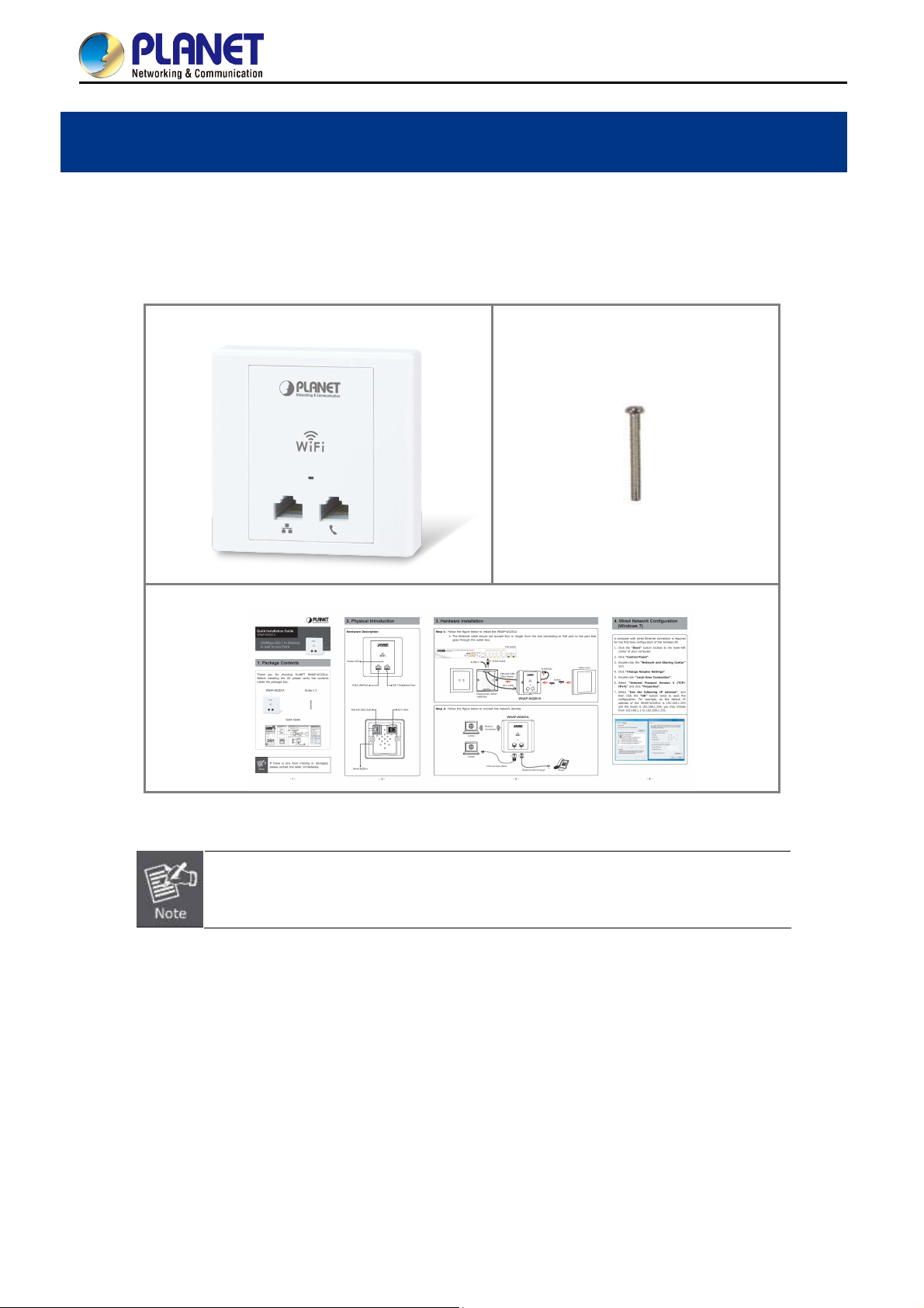
1.1 Package Contents
Thank you for choosing PLANET WNAP-W2201A. Before installing the AP, please verify the contents inside the
package box.
WNAP-W2201A
Screw x 2
Quick Guide
If there is any item missing or damaged, please contact the seller immediately.
-1-
Page 11
User Manual of WNAP-W2201A
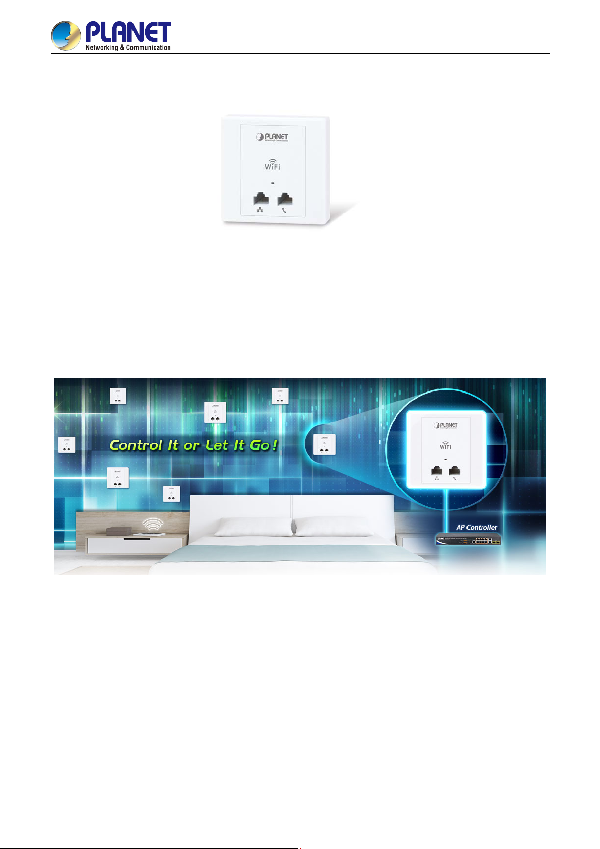
1.2 Product Description
All-in-One Manageable Wi-Fi Solution for Hospitality Industry
PLANET WNAP-W2201A enables hospitality industry to build a high-speed wireless network with a maximum
data rate of 11n 300Mbps via PLANET AP controller. Furthermore, it conforms to standard 86-type electrical
junction box and IEEE 802.3af PoE, suitable for in-wall installation. The WNAP-W2201A has also a built-in RJ11
port for phone pass-through and
enabling to integrate a hotel network with its all-in-one interface. This definitely helps guests gain
experience.
100BASE-TX RJ45 port for Ethernet connection to such device as IPTV or laptop,
good user
Ease of Deployment with PLANET AP Controller
To expand the capability of in-wall AP, PLANET WNAP-W2201A comes with centralized management, enabling
the hospitality industry to deploy multiple APs with a single interface of AP controller and reducing repetitive
tasks including AP provisioning, AP status monitoring and AP maintenance. In addition, by connecting with
PLANET WAPC AP controller series, the WNAP-W2201A comes with PoE alive check and PoE schedule
features, which help hoteliers optimize their wireless network within minutes.
-2-
Page 12

User Manual of WNAP-W2201A
Suitable for Any Room Installation without Breaking Interior Design
Featuring attractive in-wall design, the WNAP-W2201A can be firmly installed into the wall via the standard 86 x
86 mm or 75 x 75 mm European outlet box, which
installation
without affecting the original interior design. It is ideal for hotels, residences, hospitals and more to
makes electrical wiring invisible and convenient for room
establish wireless network.
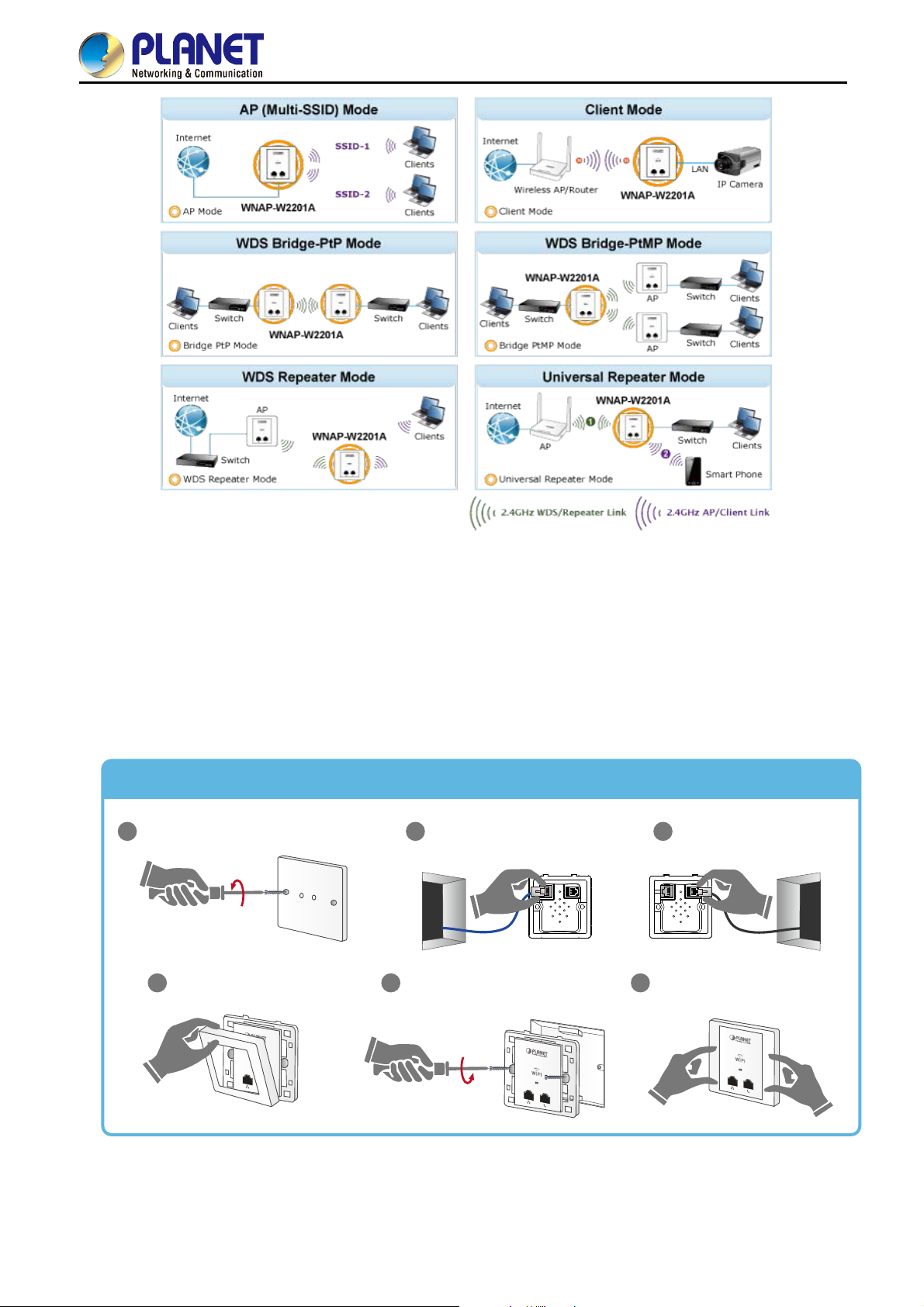
Comprehensive Wireless Operation Mode
The WNAP-W2201A supports multiple wireless communication connectivities such as AP (Multi-SSIDs), Client,
Repeater/Universal Repeater, WDS Point-to-Point (PtP) and WDS Point-to-Multipoint (PtMP), allowing
users to comprehensively experience various applications.
-3-
Page 13
User Manual of WNAP-W2201A
Easy to Install and Manage
Integrated with RJ11 phone pass-through, RJ45 Ethernet connection and IEEE 802.3af PoE PD scheme, the
WNAP-W2201A is easy to be installed to any room’s existing 86-type or 75-type junction box with only 6 steps.
The setup wizard and on-line help can simplify the configuration even for a user who has never experienced in
setting up a wireless network. In aspect of centralized management, besides the SNMP, multiple devices can be
configured and monitored by PLANET AP controller. The WNAP-W2201A helps the system administrator
overcome the difficulties of wireless deployment.
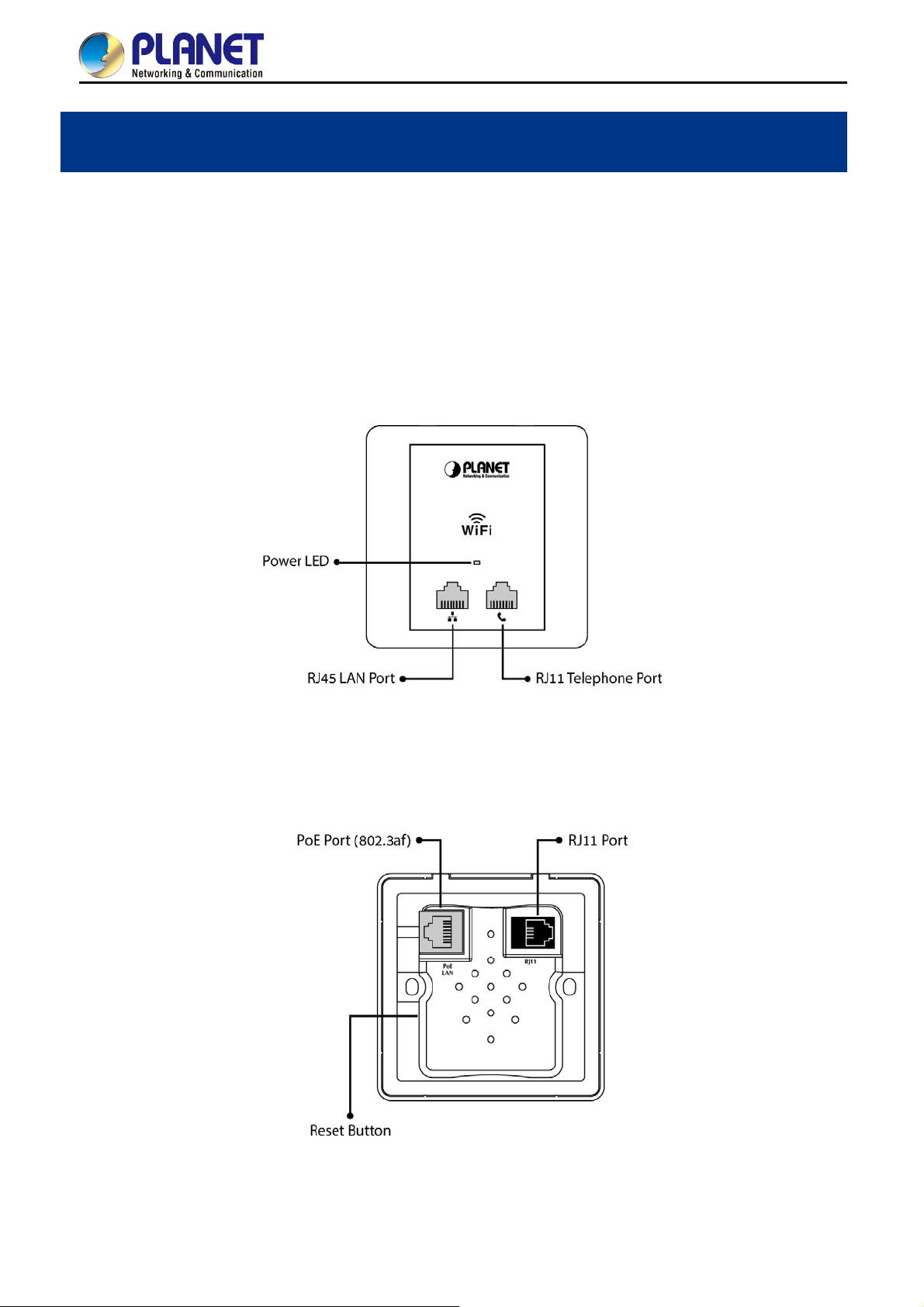
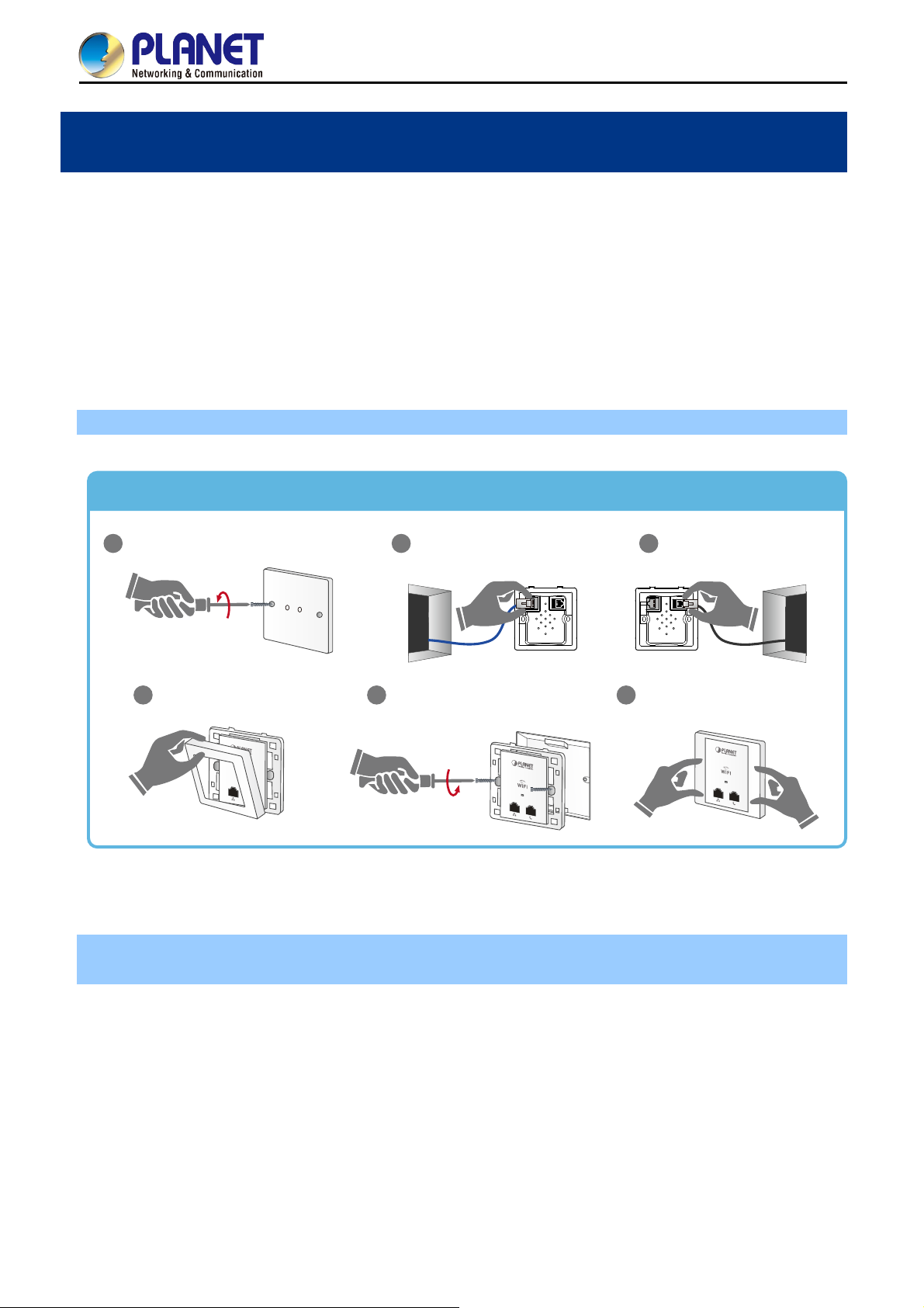
Easy 6-Step Installation
Dismantle the existing panel in the wall
1
Open the front panel
4
Connect network cable to
2
the PoE Port
Screw the AP on the wall
5
RJ11
PoE
LAN
Connect Phone wire to
3
the RJ11 Port
RJ11
PoE
LAN
Place the front panel over AP to
6
tightly close, and turn it on
-4-
Page 14

1.3 Product Features
Standard Compliant Hardware Interface
Compliant with IEEE 802.11n wireless technology with data rate of up to 300Mbps
One 10/100BASE-TX port and one PoE powered device (PD) port
One RJ11 port for phone line connection
European 86-type and 75-type wall outlet compatibility
Secure Network Connection
Advanced security: 64-/128-bit WEP, WPA/WPA2 and WPA-PSK/WPA2-PSK (TKIP/AES
encryption), 802.1x
Supports wireless MAC address filtering control to limit the connected wireless clients
Comprehensive Wireless Advanced Features
Multiple operation modes including AP (Multi-SSIDs), Client, Repeater/Universal Repeater, WDS
Point-to-Point (PtP) and WDS Point-to-Multipoint (PtMP)
Up to 5 multiple-SSIDs to allow users to access different networks through a single AP
Supports WMM (Wi-Fi Multimedia) and wireless QoS to enhance the efficiency of multimedia
application
Supports IAPP (Inter Access Point Protocol) wireless roaming to enable clients to roam across
multiple APs
Provides 5-level Transmit Power Control to adapt various environments
Wireless schedule allows administrators to enforce time-based internet access
Self-healing (Schedule Reboot) mechanism for reliable connection
User Manual of WNAP-W2201A
Easy Deployment & Centralized Management
Supports AP controller to enable administrator to configure and monitor multiple APs
simultaneously
Flexible deployment with standard 802.3af PoE/PD supported
Stylish in-wall design perfectly matches the room decoration
Step-by-step configuration with intelligent setup wizard and graphical Web-based UI
Supports SNMP-based management interface
System status monitoring including associated client list and system log
-5-
Page 15

1.4 Product Specifications
User Manual of WNAP-W2201A
Product
WNAP-W2201A
300Mbps 802.11n Wireless In-wall PoE Access Point
Hardware Specifications
PoE Port
1 x 10/100Mbps auto MDI/MDI-X RJ45 port (rear panel)
※ IEEE 802.3af PoE PD Port
Interface
LAN Port 1 x 10/100Mbps auto MDI/MDI-X RJ45 port
RJ11 Port Connect to the telephone through the 4-conductor phone line
PoE 802.3af PoE PD, Class 3
Antenna Built-in 3dBi antenna x 2
Reset Button
Reset button on side panel
(Press over 5 seconds to reset the device to factory default)
LED Indicators PWR/SYS LED
Material Plastic
Dimensions (W x D x H) 86 x 35 x 86 mm
Weight 76g
Power Requirements 802.3af/at PoE, 48-56V DC input, 0.35A (max.)
Power Consumption < 10W
Wireless interface Specifications
Standard Compliant with IEEE 802.11b/g/n
Frequency Band
Europe -- ETSI: 2.412~2.472GHz
Operating Channel Europe -- ETSI: 1~13
Channel Width 20 or 20/40MHz
802.11n (HT40): 270/243/216/162/108/81/54/27Mbps
135/121.5/108/81/54/40.5/27/13.5Mbps (dynamic)
Data Transmission
Rates
802.11n (HT20): 130/117/104/78/52/39/26/13Mbps
65/58.5/52/39/26/19.5/13/6.5Mbps (dynamic)
802.11g: 54/48/36/24/18/12/9/6Mbps (dynamic)
802.11b: 11/5.5/2/1Mbps (dynamic)
802.11n: up to 70m
Transmission Distance
802.11g: up to 30m
The estimated transmission distance is based on the theory.
The actual distance will vary in different environments.
802.11n: 17 ± 2dBm
Max. RF Power
802.11g: 17 ± 2dBm
802.11b: 18 ± 2dBm
IEEE 802.11b: -92dBm @ 1Mbps; -85dBm @ 11Mbps, PER < 8%
Receiver Sensitivity
IEEE 802.11g: -88dBm @ 6Mbps; -73dBm @ 54Mbps, PER <10%
IEEE 802.11n: -90dBm @ MCS8; -70dBm @ MCS15, PER <10%
IEEE 802.11b: 1/2/5.5/11Mbps
Data Rate
IEEE 802.11g: 6/9/12/18/24/36/48/54Mbps
IEEE 802.11n:
300 Mbps in 40MHz mode/150Mbps in 20MHz mode
TX Power Provides 5-level Tx Power Control (100%, 70%, 50%, 35%, 15%)
-6-
Page 16

Wireless Management Features
User Manual of WNAP-W2201A
Operation Mode
Standalone AP
Managed AP
AP (Multiple-SSIDs)
Client
Wireless Mode
Repeater (WDS+AP)
Universal Repeater (AP+Client)
WDS PtP Bridge
WDS PtMP Bridge
WEP (64-/128-bit) encryption security
Encryption Security
WPA/WPA2 (TKIP/AES)
WPA-PSK/WPA2-PSK (TKIP/AES)
802.1x RADIUS Authentication
Wireless MAC address filtering (up to 20 entries)
Wireless Security
Supports WPS (Wi-Fi Protected Setup)
SSID broadcast and hide
Supports WMM (Wi-Fi Multimedia) for better data transmission of video or
on-line demand
Supports wireless schedule
Wireless Advanced
Multiple SSIDs: up to 5
Wireless Isolation: Enables it to isolate each connected wireless client of a
BSSID from communicating with each other
IAPP (Inter Access Point Protocol): 802.11f wireless roaming
Provides wireless statistics, max. associated station number
Max. Supported Clients
Wired: 253
2.4GHz Wireless: 32
Built-in DHCP server supporting static IP address distribution
LAN
Supports static IP and dynamic IP
Supports UPnP
Supports 802.1d Spanning Tree
Web-based (HTTP) management interface
Supports SNTP synchronization
Easy firmware upgrade via HTTP/TFTP (through AP controller)
System Management
Easily locate deployed APs through the LED control
Supports SNMP management, LED On/Off control, Schedule Reboot
Supports Smart Discovery Utility, System Log
Supports WAPC series of AP controllers for central management
Max. WDS Peers 8
IEEE 802.11n (2T2R, up to 300Mbps)
IEEE 802.11g
IEEE 802.11b
IEEE Standards
IEEE 802.11i
IEEE 802.3 10BASE-T
IEEE 802.3u 100BASE-TX
IEEE 802.3x flow control
Other Protocols and CSMA/CA, CSMA/CD, TCP/IP, DHCP, ICMP, SNTP
-7-
Page 17

Standards
Environment & Certification
Temperature
Operating: -10 ~ 50 degrees C
Storage: -40 ~ 70 degrees C
User Manual of WNAP-W2201A
Humidity
Operating: 10 ~ 90% (non-condensing)
Storage: 5 ~ 90% (non-condensing)
Regulatory CE, RoHS
-8-
Page 18
Chapter 2. Hardware Introduction
2.1 Product Outlook
Dimensions: 86 x 35 x 86 mm
2.1.1 Panel Layout
The front and rear panels provide a simple interface monitoring the AP.
Front Panel
User Manual of WNAP-W2201A
Rear Panel
Figure 2-1 WNAP-W2201A Front Panel
Figure 2-2 WNAP-W2201A Rear Panel
-9-
Page 19
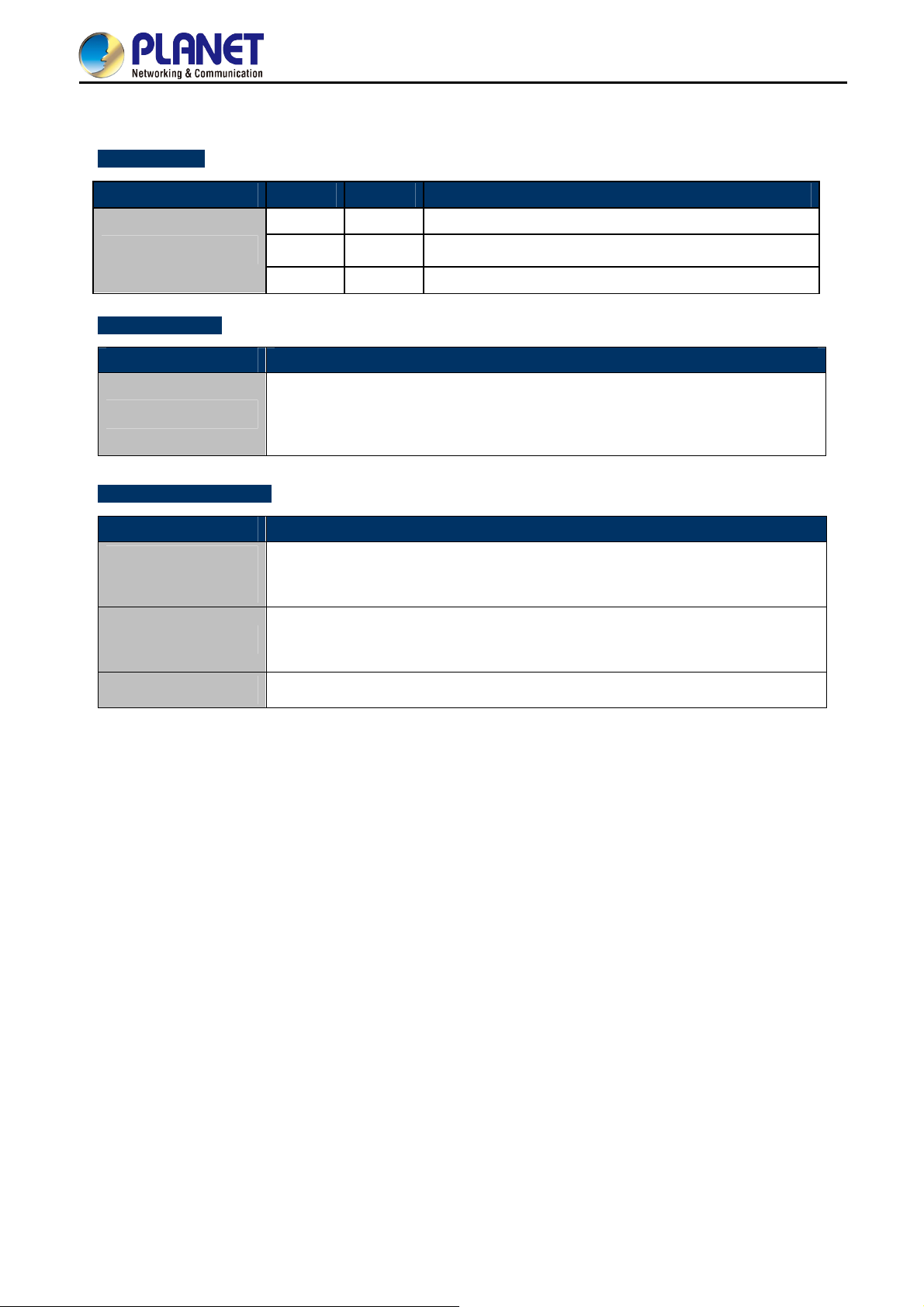
2.1.2 Hardware Description
LED Definition
LED COLOR STATUS FUNCTION
Green
On
User Manual of WNAP-W2201A
Device power on
PWR
Green
Green
Flash
Off
Detect and identify the LED (controlled by S/W)
Device power off (controlled by S/W)
Button definition
Object Description
Press the Reset button for over 5 seconds and then release it to restore system
Reset
to the factory default settings.
H/W Interface definition
Object Description
PoE Port
(802.3af/at PoE)
10/100bps RJ45 port, auto MDI/ MDI-X
Connect PoE port to the IEEE 802.3af/at PoE switch to power on the device.
10/100Mbps RJ45 port, auto MDI/ MDI-X
LAN Port
Connect this port to the network equipment.
RJ11 Port
Connect to the telephone through the 4-conductor RJ11 phone line
-10-
Page 20
User Manual of WNAP-W2201A
Easy 6-Step Installation
Dismantle the existing panel in the wall
1
Connect network cable to
the PoE Port
2
PoE
LAN
RJ11
Connect Phone wire to
the RJ11 Port
3
PoE
LAN
RJ11
Open the front panel
4
Screw the AP on the wall
5
Place the front panel over AP to
tightly close, and turn it on
6
Chapter 3. Hardware Installation
3.1 Installing the AP
Before installing the AP, make sure your PoE switch is connected to the Internet through the broadband service
successfully at this moment. If there is any problem, please contact your local ISP. After that, please install the
AP according to the following steps. Don't forget to pull out the power plug and keep your hands dry.
3.1.1 Installing the AP – WNAP-W2201A
Step 1. Follow the figure below to install WNAP-W2201A.
Figure 3-1 WNAP-W2200 Installation Diagram 1
※ The Ethernet cable should not exceed 8cm in length from the end connecting to PoE port to the part
that goes through the outlet box.
-11-
Page 21
Wireless AP Controller with 8-Port 802.3at PoE+
WAPC-1232HP
Alert
FAN
ACTLNK
PoE In-Use
PWR
2 4 6 8
1SYS
3 5 7
PoE
To PBX
User Manual of WNAP-W2201A
PoE Switch
10
Mini-GBIC
9
11 12
Console
115200,N,8,1
4 6 82
1 3 5 7
ACTLNK
10 12
1000
9 11
RESET
To PoE Switch
Ethernet Cable
(Data+Power)
RJ11 Cable
European 86 x 86mm
Outlet Box
WNAP-W2201A
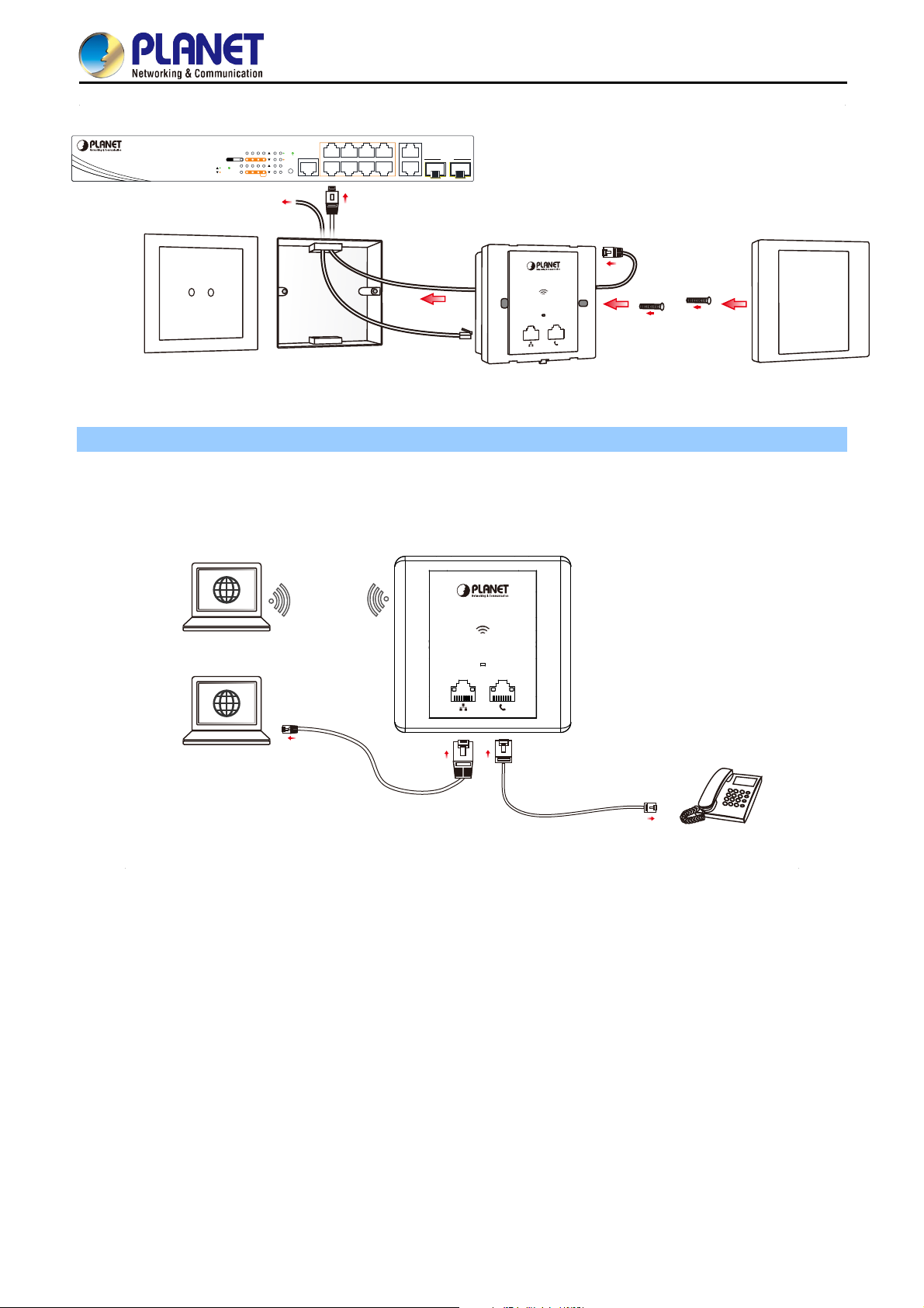
Step 2. Follow the figure below to connect the network devices.
WNAP-W2201A
Wireless
Connection
Laptop
WiFi
WiFi
To PoE Port
Outer Cover
Screws
Laptop
Ethernet Cable (Data)
Telephone Pass-through
Figure 3-3 WNAP-W2201A Installation Diagram 3
Phone
-12-
Page 22

User Manual of WNAP-W2201A
Chapter 4. Connect to the AP
This chapter will show you how to configure the basic functions of your AP within minutes.
A computer with wired Ethernet connection to the Wireless AP is required for the first-time
configuration.
4.1 System Requirements
Broadband Internet Access Service (Cable/xDSL/Ethernet connection)
One IEEE 802.3af/at PoE switch (supply power to the WNAP-W2201A)
PCs with a working Ethernet adapter and an Ethernet cable with RJ45 connectors
PCs running Windows XP, Windows Vista, Win 7, Win8, Win10, MAC OS 9 or later, Linux, UNIX or
other platforms compatible with TCP/IP protocols
1. The AP in the following instructions refers to PLANET WNAP-W2201A.
2. It is recommended to use Internet Explore 8.0 or above to access the AP.
4.2 Manual Network Setup -- TCP/IP Configuration
The default IP address of the WNAP-W2201A is 192.168.1.253. And the default Subnet Mask is 255.255.255.0.
These values can be changed as you want. In this guide, we use all the default values for description.
Connect the WNAP-W2201A with your PC by an Ethernet cable plugging in LAN port on one side and in LAN
port of PC on the other side. Please power on the WNAP-W2201A by PoE switch through the PoE port.
In the following sections, we’ll introduce how to install and configure the TCP/IP correctly in Windows 7. And the
procedures in other operating systems are similar. First, make sure your Ethernet Adapter is working, and refer
to the Ethernet adapter manual if needed.
-13-
Page 23
User Manual of WNAP-W2201A
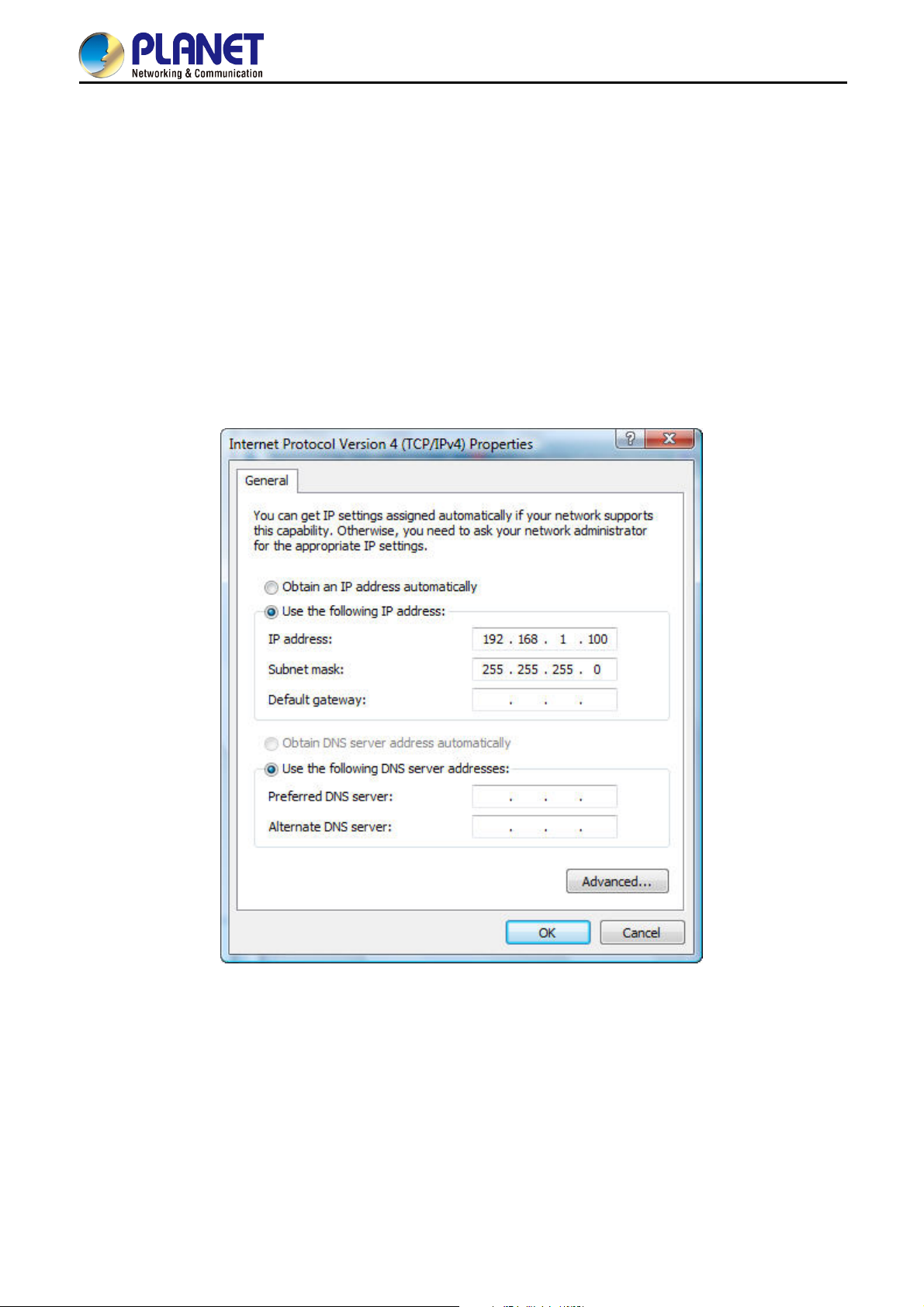
4.2.1 Configuring the IP Address Manually
Summary:
Set up the TCP/IP Protocol for your PC.
Configure the network parameters. The IP address is 192.168.1.xxx (If the default IP address of the
WNAP-W2201A is 192.168.1.253, and the DSL router is 192.168.1.254, the "xxx" can be configured to
any number from 1 to 252.) and subnet mask is 255.255.255.0.
1 Select Use the following IP address, and then configure the IP address of the PC.
2 For example, as the default IP address of the WNAP-W2201A is 192.168.1.253 and the DSL router is
192.168.1.254, you may choose from 192.168.1.1 to 192.168.1.252.
Figure 4-1 TCP/IP Setting
Now click OK to save your settings.
Now, you can run the ping command in the command prompt to verify the network connection between your
PC and the AP. The following example is in Windows 7 OS. Please follow the steps below:
1. Click on Start > Run.
-14-
Page 24
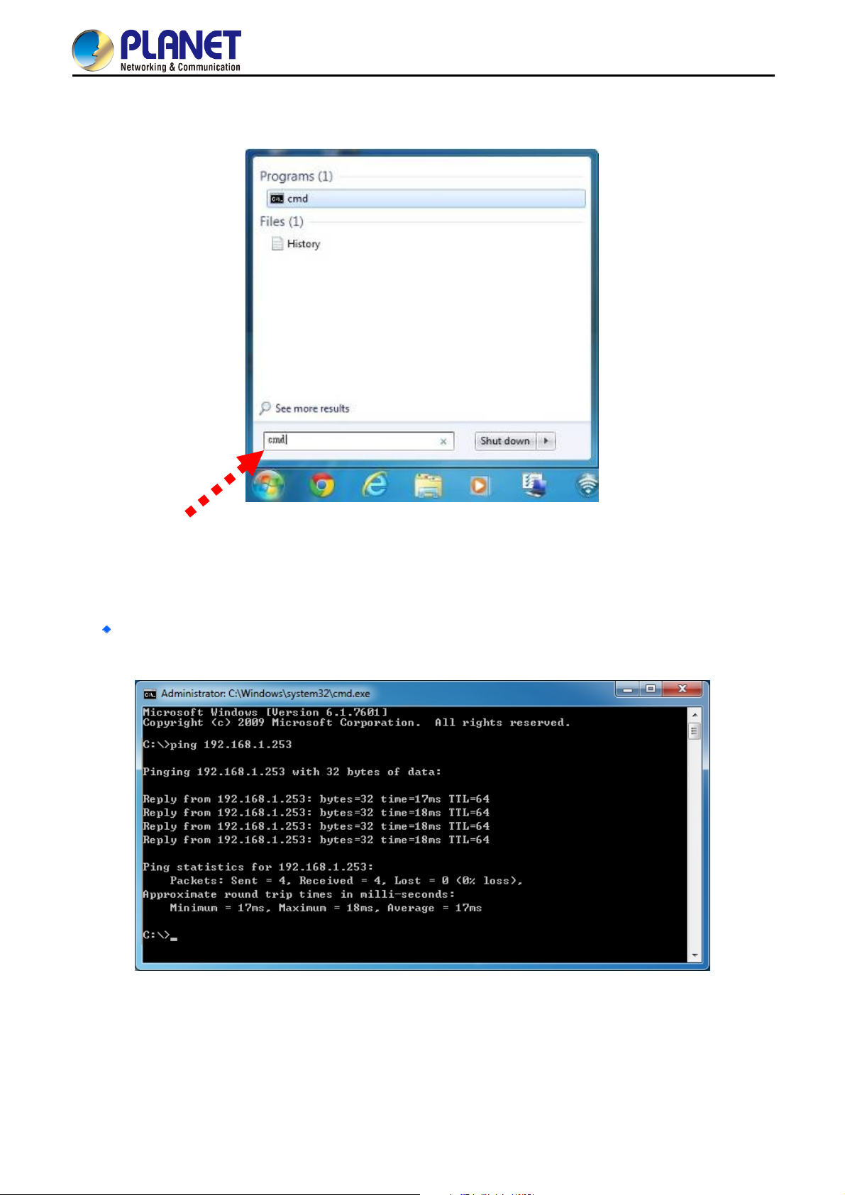
2. Type “cmd” in the Search box.
User Manual of WNAP-W2201A
Figure 4-2 Windows St
art Menu
3. Open a command prompt, type ping 192.168.1.253 and then press Enter.
If the result displayed is similar to Figure 4-3, it means the connection between your PC and the AP
has been established well.
Figure 4-3 Successful Result of Ping Command
-15-
Page 25
User Manual of WNAP-W2201A
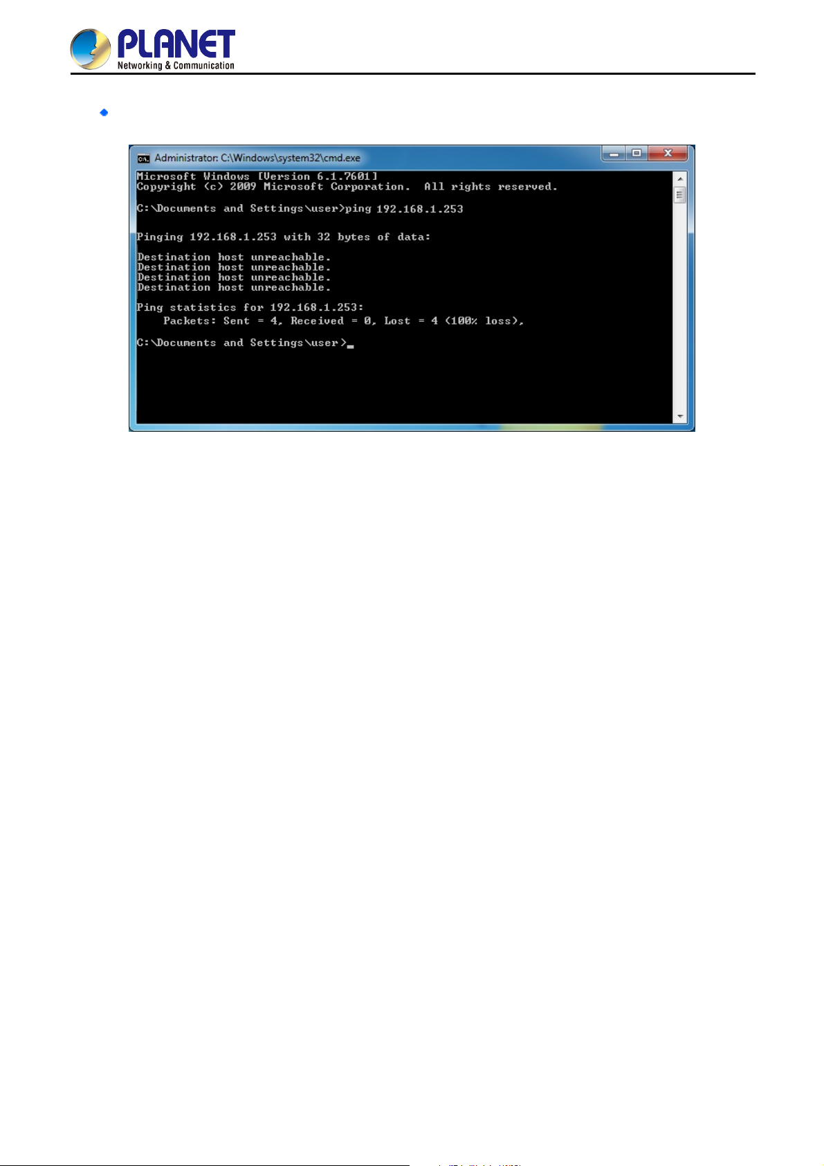
If the result displayed is similar to Figure 4-4, it means the connection between your PC and the AP
has failed.
Figure 4-4 Failed Result of Ping Command
If the address is 0.0.0.0, check your adapter installation, security settings, and the settings on your AP. Some
firewall software programs may block a DHCP request on newly installed adapters.
-16-
Page 26
User Manual of WNAP-W2201A
4.3 Starting Setup in the Web UI
It is easy to configure and manage the AP with the web browser.
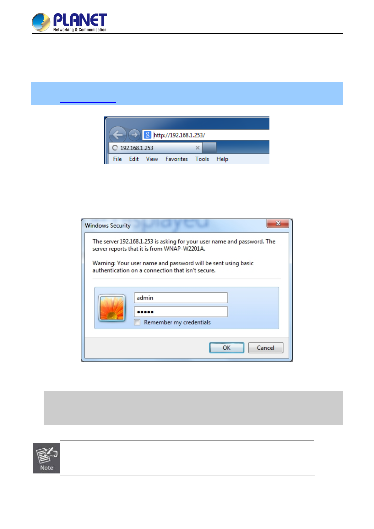
Step 1. To access the configuration utility, open a web-browser and enter the default IP address
http://192.168.1.253 in the web address field of the browser.
Figure 4-5 Login by Default IP Address
After a moment, a login window will appear. Enter admin for the User Name and Password, both in lower case
letters. Then click OK or press the Enter key.
Default IP Address: 192.168.1.253
Default User Name: admin
Default Password: admin
If the above screen does not pop up, it may mean that your web browser has been set to a
proxy. Go to Tools menu> Internet Options> Connections> LAN Settings on the screen that
appears, uncheck Using Proxy and click OK to finish it.
Figure 4-6 Login Window
-17-
Page 27
User Manual of WNAP-W2201A
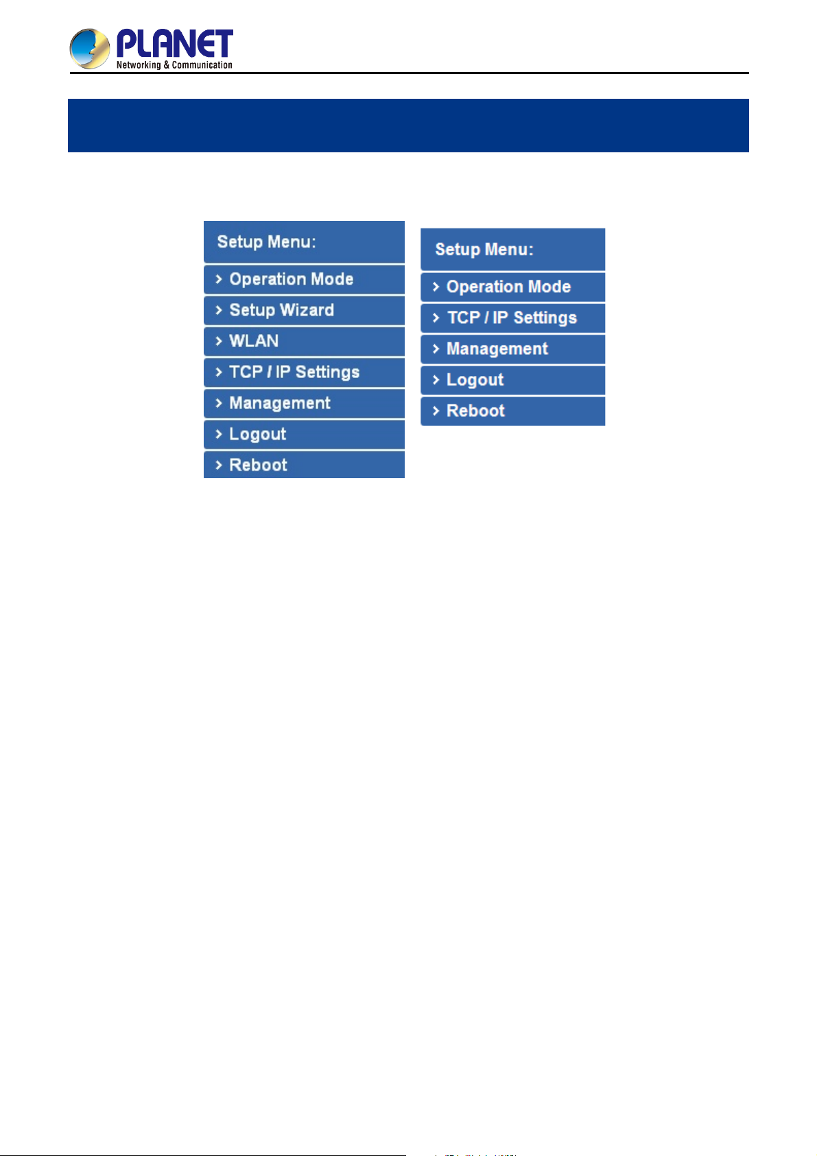
Chapter 5. Configuring the AP
This chapter delivers a detailed presentation of AP’s functionalities and features the main items below, allowing
you to manage the AP with ease.
Standalone AP Mode Managed AP Mode
Figure 5-1 Main Menu
During operation, if you are not clear about a certain feature, you can refer to the “Help” section at the right side
of the screen to read all the related helpful information.
5.1 Operation Mode
The Operation Mode section guides you to configuring the WNAP-W2201A to Standalone AP or Managed AP.
When switching the operation mode to Managed AP, the administrator will be able to manage the AP by
PLANET Wireless AP Controller. To configure the managed AP by PLANET Wireless AP Controller, please refer
to the WAPC-1232HP/WAPC-2864HP AP Management user’s manual.
-18-
Page 28
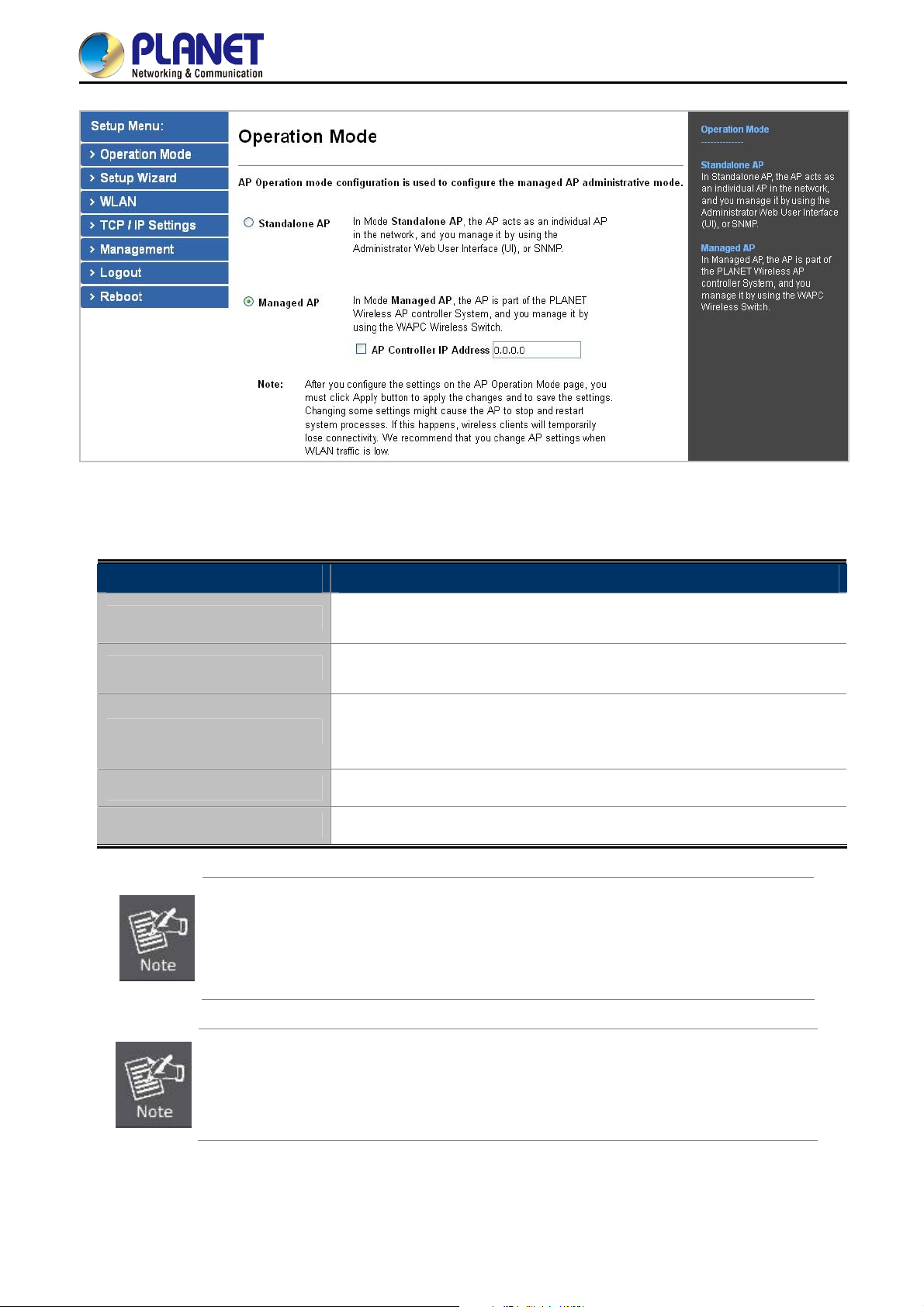
Figure 5-2 Operation Mode
User Manual of WNAP-W2201A
The page includes the following fields:
Object Description
Standalone AP
Managed AP
AP Controller IP Address
Apply Change
Reset
In Standalone AP, the AP acts as an individual AP in the network, and you
manage it by using the Administrator Web User Interface (UI), or SNMP.
In Managed AP, the AP is part of the PLANET Wireless AP controller System, and
you manage it by using the WAPC Wireless AP controller.
Check this option and enter the IP address of the AP controller that user
specifies. The default “0.0.0.0” means any AP controller existed in the local
network can control this AP.
Click “Apply Change” to save and apply the settings.
Click “Reset” to erase all settings.
After you configure the settings on the AP Operation Mode page, you must click Apply
to apply the changes and to save the settings. Changing some settings might cause the
AP to stop and restart system processes. If this happens, wireless clients will
temporarily lose connectivity. We recommend that you change AP settings when WLAN
traffic is low.
Please back up the configuration settings before switching from the Standalone AP
mode to the Managed AP mode.
All the configurations will be erased and at the same time, the system will return to the
factory default settings once it is reverted to the Standalone AP mode.
-19-
Page 29
User Manual of WNAP-W2201A
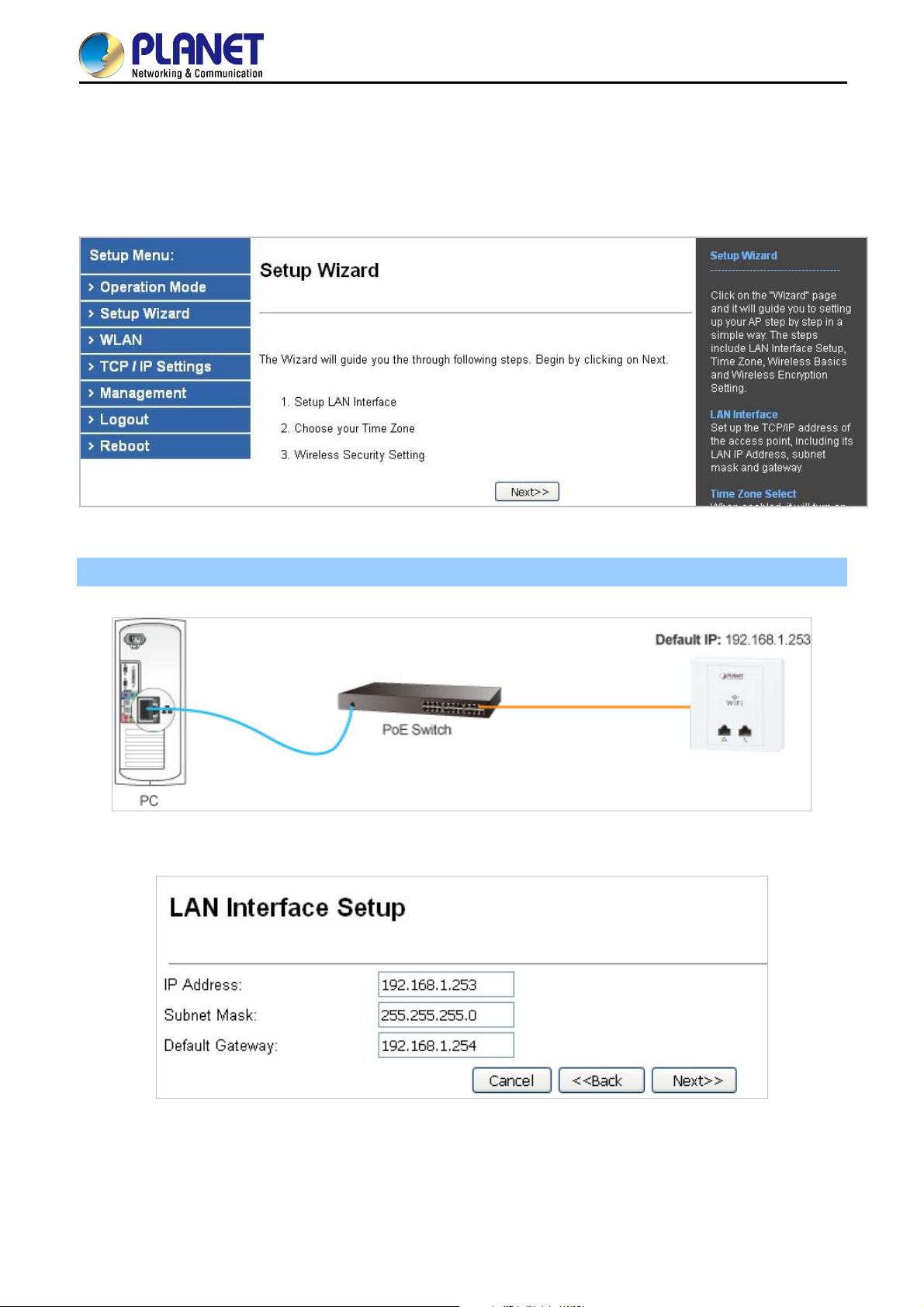
5.2 Setup Wizard
The Setup Wizard will guide the user to configuring the WNAP-W2201A easily and quickly. Select Setup Wizard
on the left side of the screen and by clicking on Next on the Setup Wizard screen shown below, you will then
name your WNAP-W2201A and set up its security.
Figure 5-3 Setup Wizard
Step 1. LAN Interface Setup
Figure 5-4 LAN Interface Setup Topology
Figure 5-5 Wizard – LAN Interface Setup
-20-
Page 30

The page includes the following fields:
Object Description
User Manual of WNAP-W2201A
IP Address
Subnet Mask
Default Gateway
Step 2. Time Zone Setting
Displays the current IP address of the AP. (Default = 192.168.1.253)
Displays LAN mask of the AP. (Default = 255.255.255.0)
IP address of the associated router. (Default = 192.168.1.254)
Figure 5-6 Time Zone Setup Topology
Figure 5-7 Wizard – Time Zone Setup
The page includes the following fields:
Object Description
Enable NTP Client Update
Automatically Adjust
Daylight Saving
Check this box to connect NTP Server and synchronize internet time.
Check this box and system will adjust the daylight saving
automatically.
-21-
Page 31

User Manual of WNAP-W2201A
Time Zone Select
NTP Server
Enable NTP Client Update
Step 3. Wireless Basic Settings
Select the Time Zone from the drop-down menu.
Select the NTP Server from the drop-down menu.
Check this box to connect NTP Server and synchronize internet time.
Figure 5-8 Wizard – Wireless Basic Settings
The page includes the following fields:
Object Description
Supports 802.11b, 802.11g, 802.11n and mixed mode. Please choose its
Band
Mode
SSID
band according to your clients.
Supports AP, Client, WDS and AP+WDS mode.
Service Set Identifier identifies your wireless network.
Select 40MHz if you use 802.11n, otherwise, 20MHz is for the 802.11b/g
Channel Width
Control Sideband
Channel Number
mode.
It is only valid when you choose a 40MHz channel width.
Indicates the channel setting for the AP.
Step 4. Wireless Security Settings
Secure your wireless network by turning on the WPA or WEP security feature on the router. For this section, you
can set WEP and WPA-PSK security mode.
-22-
Page 32

Figure 5-9 Wizard – Wireless Security Setup
Encryption: WEP
The following picture shows how to set the WEP security.
User Manual of WNAP-W2201A
Figure 5-10 Wireless Security Setup – WEP Setting
The page includes the following fields:
Object Description
Key Length
Key Format
Key Setting
WEP supports 64-bit or 128-bit security key.
User can enter key in ASCII or Hex format.
Enter the key whose format is limited by the key format, ASCII or Hex.
Encryption: WPA-PSK
The following picture shows how to set WPA-PSK security. You can select WPA (TKIP), WPA2 (AES) and
Mixed mode.
-23-
Page 33

Figure 5-11 Wireless Security Setup – WPA Setting
The page includes the following fields:
Object Description
Pre-shared Key Format
User Manual of WNAP-W2201A
Specify the format of the key, pass phrase or hex.
Pre-shared Key
Enter the key whose format is limited by the key format.
Click Finished making your wireless configuration effective and finishing the Setup Wizard.
After rebooting, please check whether you can access the Internet or not on the “Status” page.
-24-
Page 34

User Manual of WNAP-W2201A
5.3 TCP/IP Settings
This page is used to configure the parameters for local area network which connects to the LAN port of your AP.
Here you may change the setting for IP address, subnet mask, DHCP, etc.
5.3.1 LAN Settings
On the LAN Settings page, you can configure the IP parameters of the LAN on the screen as shown below.
Figure 5-12 LAN Setting
-25-
Page 35

The page includes the following fields:
Object Description
User Manual of WNAP-W2201A
IP Address
The default LAN IP address of the WNAP-W2201A is 192.168.1.253.
You can change it according to your request.
Subnet Mask Default is 255.255.255.0. You can change it according to your request.
Default Gateway Default is 192.168.1.254. You can change it according to your request.
You can select a Disabled, Client, and Server. Default is Client,
DHCP
meaning the WNAP-W2201A must be connected to a router to assign
IP addresses.
For the Server mode, you must enter the DHCP client IP address
DHCP Client Range
range in the field. And you can click “Show Client” to show the Active
DHCP Client Table.
Click “Set Static DHCP” and you can reserve some IP addresses for
Static DHCP
those network devices with the specified MAC addresses anytime
when they request IP addresses.
Domain Name Default is Planet.
802.1d Spanning Tree You can enable or disable the Spanning Tree function.
Clone MAC Address You can input an MAC address here for using clone function.
UPnP Enable
You can enable or disable the UPnP function. The UPnP feature allows
the devices, such as Internet computers, to access the local host
resources or devices as needed. UPnP devices can be automatically
discovered by the UPnP service application on the LAN.
If you change the IP address of LAN, you must use the new IP address to login the
AP.
When the IP address of the WNAP-W2201A is changed, the clients on the network
often need to wait for a while or even reboot before they can access the new IP
address. For an immediate access to the AP, please flush the netbios cache on the
client computer by running the “nbtstat –r” command before using the device
name of the WNAP-W2201A to access its Web Management page.
-26-
Page 36

User Manual of WNAP-W2201A
5.4 WLAN
The Wireless menu contains submenus of the settings about wireless network. Please refer to the following
sections for the details.
Figure 5-13 Wireless Main Menu
5.4.1 Basic Settings
Choose menu “WLAN Basic Settings” to configure the basic settings for the wireless network on this page.
After the configuration is done, please click “Apply Changes” to save the settings.
First of all, the wireless AP supports multiple wireless modes for different network applications, which include:
AP
Multiple SSIDs
Universal Repeater
Client
WDS
Repeater
It is so easy to combine the WNAP-W2201A with the existing wired network. The WNAP-W2201A definitely
provides a total network solution for the home and the SOHO users.
AP
Standard Access Point
-27-
Page 37

User Manual of WNAP-W2201A
Figure 5-14 Wireless Basic Settings – AP
-28-
Page 38

The page includes the following fields:
Object Description
Disable Wireless LAN
Interface
Check the box to disable the wireless function.
User Manual of WNAP-W2201A
Band
Mode
SSID
Channel Width
Select the desired mode. Default is “2.4GHz (B+G+N)”. It is strongly
recommended that you set the Band to “2.4GHz (B+G+N)”, and all of
802.11b, 802.11g, and 802.11n wireless stations can connect to the
WNAP-W2201A.
2.4 GHz (B): 802.11b mode, rate is up to 11Mbps
2.4 GHz (G): 802.11g mode, rate is up to 54Mbps
2.4 GHz (N): 802.11n mode, rate is up to 300Mbps(2T2R)
2.4 GHz (B+G): 802.11b/g mode, rate is up to 11Mbps or 54Mbps
2.4 GHz (G+N): 802.11g/n mode, rate is up to 54Mbps or 300Mbps
2.4 GHz (B+G+N): 802.11b/g/n mode, rate is up to 11Mbps,
54Mbps, or 300Mbps
There are four kinds of wireless mode selections:
AP
Client
WDS
Repeater
If you select WDS or Repeater, please click “WDS Settings” in the
submenu for the related configuration. Furthermore, click “Multiple
AP” to enable multiple SSID functions.
It’s the ID of the wireless network. User can access the wireless
network via the ID only. However, if you switch to Client Mode, this
field becomes the SSID of the AP you want to connect with.
Default: PLANET_XXXX (“X” means the last 4 digits of the MAC
address)
You can select 20MHz, or 40MHz.
Channel Number
Broadcast SSID
Data Rate
You can select the operating frequency of wireless network.
Default: 11
If you enable “Broadcast SSID”, every wireless station located within
the coverage of the AP can discover its signal easily. If you are building
a public wireless network, enabling this feature is recommended. In
private network, disabling “Broadcast SSID” can provide better
wireless network security.
Default is “Enabled”.
Set the wireless data transfer rate to a certain value. Since most of
wireless devices will negotiate with each other and pick a proper data
transfer rate automatically, it’s not necessary to change this value
unless you know what will happen after modification.
Default is “Auto”.
-29-
Page 39

User Manual of WNAP-W2201A
Associated Clients Click “Show Active Clients” to show the status table of active wireless
clients.
Enable Universal
Repeater Mode
(Acting as AP and client
simultaneously)
Universal Repeater is a technology used to extend wireless coverage.
To enable Universal Repeater mode, check the box and enter the
SSID you want to broadcast in the field below. Then please click
“Security” in the submenu for the related settings of the AP you want
to connect with.
Multiple-SSIDs
Enabling multiple-SSIDs can broadcast multiple WLAN SSIDs using virtual interfaces. You can have
different encryption settings for each WLAN and you can restrict what they have access to.
Choose menu “WLAN Basic Settings Multiple AP” to configure the device as a general wireless
access point with multiple SSIDs.
Figure 5-15 Wireless Basic Settings – Multiple APs
The device supports up to four multiple Service Set Identifiers. You can go back to the Basic Settings page
to set the Primary SSID. The SSID’s factory default setting is PLANET_XXXX (Multiple-SSID 1~4). The
SSID can be easily changed to connect to an existing wireless network or to establish a new wireless
network. When the information for the new SSID is finished, click Apply Changes to let your changes take
effect.
-30-
Page 40

User Manual of WNAP-W2201A
Figure 5-16 Multiple-SSIDs
Once you have applied and saved those settings, you can then go to the “WLAN Security” page on the
AP to set up security settings for each of the SSIDs.
Universal Repeater
This mode allows the AP with its own BSS to relay data to a root AP to which it is associated with WDS
disabled. The wireless repeater relays signal between its stations and the root AP for greater wireless
range.
Example of how to configure Universal Repeater Mode. Please take the following steps:
To configure each wireless parameter, please go to the “WLAN Basic Settings” page.
Step 1. Configure wireless mode to “AP” and then check “Enable Universal Repeater Mode (Acting as AP
and client simultaneously)”. Click “Apply Changes” to take effect.
-31-
Page 41

Figure 5-17 Universal Repeater-1
User Manual of WNAP-W2201A
Step 2. Go to Site Survey page to find the root AP. Select the root AP that you want to repeat the signal, and
then click “Next”.
Figure 5-18 Universal Repeater-2
Step 3. Select the correct encryption method and enter the security key. Then click “Connect”.
-32-
Page 42

User Manual of WNAP-W2201A
Figure 5-19 Universal Repeater-3
Step 4. Check “Add to Wireless Profile” and click “Reboot Now”.
Figure 5-20 Universal Repeater-4
Step 5. Go to the “Management-> Status” page to check whether the state of Repeater interface should be
“Connected”.
Figure 5-21 Universal Repeater-5
-33-
Page 43

User Manual of WNAP-W2201A
Client (Infrastructure)
Combine the Wireless Router to the Ethernet devices such as TV, Game player, or HDD and DVD, to make
them be wireless stations.
Figure 5-22 Wireless Basic Settings – Client
-34-
Page 44

The page includes the following fields:
Object Description
Disable Wireless LAN
Check the box to disable the wireless function.
Interface
User Manual of WNAP-W2201A
Band
Mode
Select the desired mode. Default is “2.4GHz (B+G+N)”. It is strongly
recommended that you set the Band to “2.4GHz (B+G+N)”, and all of
802.11b, 802.11g, and 802.11n wireless stations can connect to the
WNAP-W2201A.
2.4 GHz (B): 802.11b mode, rate is up to 11Mbps
2.4 GHz (G): 802.11g mode, rate is up to 54Mbps
2.4 GHz (N): 802.11n mode, rate is up to 300Mbps(2T2R)
2.4 GHz (B+G): 802.11b/g mode, rate is up to 11Mbps or 54Mbps
2.4 GHz (G+N): 802.11g/n mode, rate is up to 54Mbps or 300Mbps
2.4 GHz (B+G+N): 802.11b/g/n mode, rate is up to 11Mbps,
54Mbps, or 300Mbps
There are four kinds of wireless mode selections:
AP
Client
WDS
Repeater
If you select WDS or Repeater, please click “WDS Settings” in the
submenu for the related configuration. Furthermore, click “Multiple
AP” to enable multiple SSID functions.
Network Type
SSID
Broadcast SSID
In Infrastructure, the wireless LAN serves as a wireless station. And
the user can use the PC equipped with the WNAP-W2201A to access
the wireless network via other access points. In ad hoc, the wireless
LAN will use the ad-hoc mode to operate.
Default is “Infrastructure”.
Note: only while the wireless mode is set to “Client”, then the Network
Type can be configured.
It’s the ID of the wireless network. User can access the wireless
network via the ID only. However, if you switch to Client Mode, this
field becomes the SSID of the AP you want to connect with.
Default: PLANET_XXXX (“X” means the last 4 digits of the MAC
address)
If you enable “Broadcast SSID”, every wireless station located within
the coverage of the WNAP-W2201A can discover its signal easily. If
you are building a public wireless network, enabling this feature is
recommended. In private network, disabling “Broadcast SSID” can
-35-
Page 45

User Manual of WNAP-W2201A
provide better wireless network security.
Default is “Enabled”.
Data Rate
Set the wireless data transfer rate to a certain value. Since most of
wireless devices will negotiate with each other and pick a proper data
transfer rate automatically, it’s not necessary to change this value
unless you know what will happen after modification.
Default is “Auto”.
Enable Mac Clone
Enable Mac Clone.
(Single Ethernet Client)
Example of how to configure Client Mode. Please take the following steps:
To configure each wireless parameter, please go to the “WLAN Basic Settings” page.
Step 1. Go to the “WLAN Site Survey” page and click “Site Survey”.
Figure 5-23 Client – Survey
-36-
Page 46

User Manual of WNAP-W2201A
Step 2. Choose the root AP from the list. If the root AP is not listed in the table, re-click “Site Survey” to update
the list.
Figure 5-24 Client – AP List
-37-
Page 47

Step 3. Enter the Security Key of the root AP and then click “Connect”.
User Manual of WNAP-W2201A
Figure 5-25 Client – Security
Step 4. Wait until the connection is established. Check the “Add to Wireless Profile” option and then reboot it.
Figure 5-26 Client – Status
-38-
Page 48

User Manual of WNAP-W2201A
WDS
Connect this Wireless AP with up to 8 WDS-capable wireless APs to expand the scope of network.
-39-
Page 49

User Manual of WNAP-W2201A
Figure 5-27 Wireless Basic Settings – WDS
The page includes the following fields:
Object Description
Disable Wireless LAN
Check the box to disable the wireless function.
Interface
Band
Select the desired mode. Default is “2.4GHz (B+G+N)”. It is strongly
recommended that you set the Band to “2.4GHz (B+G+N)”, and all of
802.11b, 802.11g, and 802.11n wireless stations can connect to the
WNAP-W2201A.
2.4 GHz (B): 802.11b mode, rate is up to 11Mbps
-40-
Page 50

Mode
User Manual of WNAP-W2201A
2.4 GHz (G): 802.11g mode, rate is up to 54Mbps
2.4 GHz (N): 802.11n mode, rate is up to 300Mbps(2T2R)
2.4 GHz (B+G): 802.11b/g mode, rate is up to 11Mbps or 54Mbps
2.4 GHz (G+N): 802.11g/n mode, rate is up to 54Mbps or 300Mbps
2.4 GHz (B+G+N): 802.11b/g/n mode, rate is up to 11Mbps,
54Mbps, or 300Mbps
There are four kinds of wireless mode selections:
AP
Client
WDS
Repeater
If you select WDS or Repeater, please click “WDS Settings” in the
submenu for the related configuration. Furthermore, click “Multiple
AP” to enable multiple SSID function.
Channel Width
Control Sideband
Channel Number
Data Rate
You can select 20MHz, or 40MHz
You can select Upper or Lower.
You can select the operating frequency of wireless network.
Set the wireless data transfer rate to a certain value. Since most of
wireless devices will negotiate with each other and pick a proper data
transfer rate automatically, it’s not necessary to change this value
unless you know what will happen after modification.
Default is “Auto”.
Once you have applied and saved the settings of WDS mode, you can then go to the “WLAN WDS
Settings” page on the AP to set up the MAC address of the remote slave AP.
Repeater
Connect this Wireless AP with up to 8 WDS-capable wireless APs, and connect another AP to provide
service for all wireless stations within its coverage.
-41-
Page 51

User Manual of WNAP-W2201A
Figure 5-28 Wireless Basic Settings – Repeater
The page includes the following fields:
Object Description
Disable Wireless LAN
Check the box to disable the wireless function.
Interface
Band
Select the desired mode. Default is “2.4GHz (B+G+N)”. It is strongly
recommended that you set the Band to “2.4GHz (B+G+N)”, and all of
802.11b, 802.11g, and 802.11n wireless stations can connect to the
WNAP-W2201A.
-42-
Page 52

Mode
User Manual of WNAP-W2201A
2.4 GHz (B): 802.11b mode, rate is up to 11Mbps
2.4 GHz (G): 802.11g mode, rate is up to 54Mbps
2.4 GHz (N): 802.11n mode, rate is up to 300Mbps(2T2R)
2.4 GHz (B+G): 802.11b/g mode, rate is up to 11Mbps or 54Mbps
2.4 GHz (G+N): 802.11g/n mode, rate is up to 54Mbps or 300Mbps
2.4 GHz (B+G+N): 802.11b/g/n mode, rate is up to 11Mbps,
54Mbps, or 300Mbps
There are four kinds of wireless mode selections:
AP
Client
WDS
Repeater
If you select WDS or Repeater, please click “WDS Settings” in the
submenu for the related configuration. Furthermore, click “Multiple
AP” to enable multiple SSID functions.
SSID
Channel Width
Control Sideband
Channel Number
Broadcast SSID
Data Rate
It’s the ID of the wireless network. User can access the wireless
network via the ID only. However, if you switch to Client Mode, this
field becomes the SSID of the AP you want to connect with.
Default: PLANET_XXXX (“X” means the last 4 digits of the MAC
address)
You can select 20MHz, or 40MHz
You can select Upper or Lower.
You can select the operating frequency of wireless network.
If you enable “Broadcast SSID”, every wireless station located within
the coverage of the WNAP-W2201A can discover its signal easily. If
you are building a public wireless network, enabling this feature is
recommended. In private network, disabling “Broadcast SSID” can
provide better wireless network security.
Default is “Enabled”.
Set the wireless data transfer rate to a certain value. Since most of
wireless devices will negotiate with each other and pick a proper data
transfer rate automatically, it’s not necessary to change this value
unless you know what will happen after modification.
Associated Clients
Enable Universal
Repeater Mode
(Acting as AP and client
simultaneously)
Default is “Auto”.
Click “Show Active Clients” to show the status table of active wireless
clients.
Universal Repeater is a technology used to extend wireless coverage.
To enable Universal Repeater Mode, check the box and enter the
SSID you want to broadcast in the field below. Then please click
“Security” in the submenu for the related settings of the AP you want
to connect with.
-43-
Page 53

User Manual of WNAP-W2201A
5.4.2 Advanced Settings
Choose menu “WLAN Advanced Settings” to configure the advanced settings for the wireless network on
this page. After the configuration, please click “Apply” to save the settings.
Figure 5-29 Wireless Advanced Settings
The page includes the following fields:
Object Description
Fragment Threshold You can specify the maximum size of packet during the fragmentation
of data to be transmitted. If you set this value too low, it will result in
bad performance.
Default is “2346”.
RTS Threshold When the packet size is smaller than the RTS threshold, the access
point will not use the RTS/CTS mechanism to send this packet.
Default is “2347”.
Beacon Interval The interval of time that this access point broadcasts a beacon.
Beacon is used to synchronize the wireless network. Default is “100”.
IAPP IAPP (Inter-Access Point Protocol) enabled is recommended as it
describes an optional extension to IEEE 802.11 that provides wireless
access-point communications among multivendor systems.
Default is “Enabled”.
-44-
Page 54

User Manual of WNAP-W2201A
Protection It is recommended to enable the protection mechanism. This
mechanism can decrease the rate of data collision between 802.11b
and 802.11g wireless stations. When the protection mode is enabled,
the throughput of the AP will be a little lower due to the transmission of
heavy frame traffic.
Default is “Disabled”.
Aggregation It is a function where the values of multiple rows are grouped together.
Default is “Enabled”
Short GI It is used to set the time that the receiver waits for RF reflections to
settle out before sampling data.
Default is “Enabled”
WLAN Partition This feature also called “WLAN isolation” or “Block Relay”. If this is
enabled, wireless clients cannot exchange data through the
WNAP-W2201A.
Default is “Disabled”.
STBC Activate Space Time Blocking Code (STBC) which does not need
channel statement information (CSI).
Default Setting: "Enabled"
LDPC Low-density Parity-check Code is wireless data transmit algorithm.
Default Setting: "Enabled"
20/40MHz Coexist Configure 20/40MHz coexisting scheme.
If you set up as "Enabled", "20MHz" and "40MHz" will coexist.
Default Setting: "Disabled"
-45-
Page 55

User Manual of WNAP-W2201A
5.4.3 RF Output Power
Choose menu “WLAN2 (2.4GHz) RF Output Power” to adjust to different levels of transmitting power for the
wireless network according to various environment on this page. After the configuration, please click “Apply
Changes” to save the settings.
Figure 5-30 RF Output Power
RF Output Power Control provides the flexibility to control the Wi-Fi Transmit power to optimize the wireless
range. Wi-Fi power consumption for an Access Point could be reduced to up to 75% from its peak power
consumption for serving small to medium size homes, while maximum power is boosted for large homes and
businesses. The WNAP-W2201A supports output power control levels up to 5. You can change the RF output
power level here in accordance with various environments and signal strength.
-46-
Page 56

User Manual of WNAP-W2201A
5.4.4 Security
Choose menu “WLAN Security” to configure the settings of wireless security for the wireless network on this
page. After the configuration, please click “Apply Changes” to save the settings.
Figure 5-31 Wireless Security Settings
The page includes the following fields:
Object Description
Select SSID
Select the SSID you want to configure the wireless security function, which
includes the root one and the client one.
Encryption
Disable:
No security setup for wireless connection.
WEP:
It is based on the IEEE 802.11 standard. And the default setting of
authentication is Automatic, which can select Open System or Shared Key
authentication type automatically based on the wireless station's capability
and request. Furthermore, you can select Key Length and enter 10 and 26
Hexadecimal digits (any combination of 0-9, a-f, A-F, zero key is not
promoted) or 5 and 13 ASCII characters in the Encryption Key field.
WPA:
WPA is a medium level encryption and is supported by most wireless devices
and operating systems.
-47-
Page 57

User Manual of WNAP-W2201A
WPA2:
WPA2 is a high level encryption and is supported by most wireless devices
and operating systems.
WPA / WPA2 / WPA-Mixed:
WPA Mixed Mode allows the use of both WPA and WPA2 at the same time.
Authentication Mode
802.1x Authentication
Enterprise (RADIUS)
When you select the authentication mode based on Enterprise (RADIUS
Server), please enter the IP Address, Port, and Password of the RADIUS
Server.
Personal (Pre-shared Key)
When you select the other authentication mode based on Personal
(Pre-shared Key), please enter at least 8 ASCII characters (Passphrase) or
64 Hexadecimal characters. All of the Cipher Suites support TKIP and AES.
Enable 802.1x authentication function and then enter the IP Address, Port,
and Password of the RADIUS Server.
-48-
Page 58

User Manual of WNAP-W2201A
5.4.5 Access Control
Choose menu “WLAN Access Control” to allow or deny the computer of specified MAC address to connect
with the WNAP-W2201A on this page. After the configuration, please click “Apply Changes” to save the
settings.
Figure 5-32 Wireless Access Control
The page includes the following fields:
Object Description
Wireless Access
You can choose to set the Allow Listed, Deny Listed, or Disable this function.
Control Mode
MAC Address
Enter the MAC address you want to allow or deny connection to the
WNAP-W2201A in the field.
Comment
Current Access Control
You can make some comment on each MAC address on the list.
You can select some MAC addresses and click “Delete Selected” to delete it.
List
Wireless Access Control example:
To deny a PC at the MAC address of 00:30:4F:00:00:01 to connect to your wireless network, do as follows:
Step 1. Select “Deny Listed” from MAC Address Filter drop-down menu.
Step 2. Enter 00:30:4F:00:00:01 in the MAC address box and click “Add”.
-49-
Page 59

User Manual of WNAP-W2201A
Step 3. Click “OK” to save your settings and you can add more MAC addresses, if you like, simply repeat the
above steps.
Figure 5-33 Wireless Access Control – Deny
-50-
Page 60

User Manual of WNAP-W2201A
5.4.6 WDS
WDS (Wireless Distribution System) feature can be used to extend your existing wireless network coverage.
Here we present you how to configure such feature in the AP.
Before configuring the WDS Setting page, you have to select the wireless mode to “WDS” on the WLAN
Basic Settings web page.
-51-
Page 61

User Manual of WNAP-W2201A
Figure 5-34 WDS Mode
Choose menu “WLAN WDS Settings” to configure WDS to connect the WNAP-W2201A with another AP on
this page. After the configuration, please “Apply Changes” to save the settings.
Figure 5-35 WDS Settings
-52-
Page 62

Figure 5-36 WDS – Set Security
User Manual of WNAP-W2201A
The page includes the following fields:
Object Description
Enable WDS Check the box to enable the WDS function. Please select WDS or
Repeater in the Mode of Wireless Basic Settings before you enable
WDS on this page.
MAC Address You can enter the MAC address of the AP you want to connect with.
Max. 8 MAC addresses can be configured.
Data Rate Default is “Auto”.
Comment You can make some comment for each MAC address on the list.
Set Security Click “Set Security” to configure the wireless security parameters of the
AP you want to connect via WDS.
Show Statics Click “Show Statics” to show the WDS AP.
Current WDS AP List You can select some MAC addresses of the AP and click “Delete
Selected” to delete it.
WDS feature can only be implemented between 2 wireless devices that both support the
WDS feature. Plus, channel, security settings and security key must be the same on
both such devices.
To encrypt your wireless network, click “Set Security”. For the detail of wireless security,
see section 5.4.4
security settings; otherwise, the WDS feature may not function.
. Do remember to reboot the device after you save your wireless
-53-
Page 63

User Manual of WNAP-W2201A
5.4.7 Site Survey
Choose menu “WLAN Site Survey” to scan the available local AP. If any Access Point is found, you could
choose any one to connect with manually when the Client Mode is enabled.
Figure 5-37 Site Survey
-54-
Page 64

User Manual of WNAP-W2201A
5.4.8 WPS
WPS (Wi-Fi Protected Setup) is designed to ease setup of security Wi-Fi networks and subsequently network
management. This Wireless Router supports WPS features for AP mode, Repeater mode,
Infrastructure-Client mode, and the wireless root interface of Universal Repeater mode.
Figure 5-38 WPS
Simply enter a Pin code or press the software PBC button or hardware WPS button (if any) and a secure
wireless connection is established.
PBC: If you find the WPS LED blinking for 2 minutes after you press the hardware WPS button on the
device, it means that PBC encryption method is successfully enabled. And an authentication will
be performed between your router and the WPS/PBC-enabled wireless client device during this
time; if it succeeds, the wireless client device connects to your device, and the WPS LED turns
off. Repeat steps mentioned above if you want to connect more wireless client devices to the
device.
-55-
Page 65

User Manual of WNAP-W2201A
PIN:To use this option, you must know the Pin code from the wireless client and enter it in
corresponding field on your device while using the same Pin code on client side for such
connection.
The page includes the following fields:
Object Description
Disable WPS
WPS Status
Self-Pin Number
Push Button
Configuration
Client Pin Number
You can check the box to disable the WPS function.
Here you can check if the connection via WPS is established or not.
It is the Pin number of the WNAP-W2201A here.
Click “Start PBC” to activate WPS as well in the client device within 2
minutes.
In addition to the PBC method, you can also use the Pin method to
activate the WPS. Just enter the Pin number of the client device in the
field and click “Start Pin”.
The WPS encryption can be implemented only between your Router and another
WPS-capable device.
Example of how to establish wireless connection using WPS. Please take the following steps:
Step 1. Choose menu “WLAN WPS” to configure the setting for WPS. After the configuration, please click
“Apply Changes” to save the settings.
Step 2. Add a new device.
If the wireless adapter supports Wi-Fi Protected Setup (WPS), you can establish a wireless connection between
wireless adapter and AP using either Push Button Configuration (PBC) method or Pin method.
To build a successful connection by WPS, you should also do the corresponding configuration
of the new device for WPS function.
A. By Push Button Configuration (PBC)
-56-
Page 66

i. Click “Start PBC” on the WPS page of the AP.
Figure 5-39 WPS-PBC -1
User Manual of WNAP-W2201A
Figure 5-40 WPS-PBC -2
ii. Press and hold the WPS button equipped on the adapter directly for 2 or 3 seconds. Or you can click
the WPS button with the same function in the configuration utility of the adapter. The process must be
finished within 2 minutes.
iii. Wait for a while until the next screen appears. Click OK to complete the WPS configuration.
B. By Pin
If the new device supports Wi-Fi Protected Setup and the Pin method, you can add it to the network by Pin with
the following two methods.
Method One: Enter the Pin of your wireless adapter into the configuration utility of the AP
i. Enter the Pin code of the wireless adapter in the field behind Client Pin Number in the following
figure and then click Start Pin.
The Pin code of the adapter is always displayed on the WPS configuration screen.
-57-
Page 67

User Manual of WNAP-W2201A
Figure 5-41 WPS-Pin -1
Figure 5-42 WPS-Pin -2
ii. For the configuration of the wireless adapter, please choose the option that you want to enter Pin
into the AP (Enrollee) in the configuration utility of the WPS and click Next until the process finishes.
Method Two: Enter the Pin of the AP into the configuration utility of your wireless adapter
i. Click “Start PBC” on the WPS page of the AP. Get the current Pin code of the AP on WPS page (each
AP has its unique Pin code).
Figure 5-43 WPS-Pin -3
ii. For the configuration of the wireless adapter, please choose the option that you want to enter the Pin
of the AP (Registrar) in the configuration utility of the wireless adapter and enter it into the field.
Then click Next until the process finishes.
-58-
Page 68

User Manual of WNAP-W2201A
5.4.9 Schedule
Wireless Schedules will enable or disable your wireless access at a set time based on your predefined schedule.
This feature is often used for restricting access to all users (such as children, employees and guests) during
specific times of the day for parental control or security reasons.
Choose menu “WLAN Schedule” to configure the schedule rule of enabling wireless function. After the
configuration, please click “Apply Changes” to save the settings.
-59-
Page 69

User Manual of WNAP-W2201A
Figure 5-44 Schedule
When setting the Wireless Schedule, it is important to ensure that your System Clock
settings have been configured. If not, your Wireless Schedule will not function correctly.
-60-
Page 70

User Manual of WNAP-W2201A
5.5 Management
This section focuses on how to maintain AP, including Restore to Factory Default Setting, Backup/Restore,
Firmware Upgrade, Reboot, Password Change and Syslog.
Figure 5-45 Management – Main Menu
5.5.1 Status
You can use this function to realize the instantaneous information of the wireless AP. The information displayed
here may vary on different configurations.
Choose menu “Management Status” to show the current status and some basic settings of the
WNAP-W2201A.
-61-
Page 71

User Manual of WNAP-W2201A
Figure 5-46 Status
-62-
Page 72

User Manual of WNAP-W2201A
5.5.2 Statistics
Choose menu “Management Statistics” to show the packet counters for transmission and reception
regarding wireless and Ethernet network.
Figure 5-47 Statistics
The page includes the following fields:
Object Description
Wireless LAN
Sent Packets
Wireless LAN
Received Packets
Ethernet LAN
Sent Packets
Ethernet LAN
Received Packets
It shows the statistic count of sent packets on the wireless LAN interface.
It shows the statistic count of received packets on the wireless LAN interface.
It shows the statistic count of sent packets on the Ethernet LAN interface.
It shows the statistic count of received packets on the Ethernet LAN interface.
Refresh Click the refresh the statistic counters on the screen.
-63-
Page 73

User Manual of WNAP-W2201A
5.5.3 SNMP
Choose menu “Management SNMP” to enable SNMP to allow the network management station to retrieve
statistics and status from the SNMP agent in the AP. Simple Network Management Protocol (SNMP) is a popular
network monitoring and management protocol, used to refer to a collection of specifications for network
management that includes the protocol itself.
The page includes the following fields:
Object Description
Enable SNMP
Name
Location
Contact
Read/Write Community
It shows the statistic count of sent packets on the wireless LAN interface.
An administratively-assigned name for this managed node.
The physical location of this node.
The textual identification of the contact person for this managed node.
Enter the community name that allows Read/Write access to the AP's SNMP
information. The community name can be considered a group password. The
default setting is “private”.
Read-Only Community
Enter the community name that allows Read-Only access to the AP's SNMP
information. The community name can be considered a group password. The
default setting is “public”.
Trap Receiver IP
Enter the IP address s of the SNMP trap receiver.
Address
Figure 5-48 SNMP
Apply Change
Reset
Click “Apply Change” to save and apply the settings.
Click “Reset” to reset the values to default.
-64-
Page 74

User Manual of WNAP-W2201A
5.5.4 NTP Settings
This section assists you in setting the Wireless AP’s system time. You can either select to set the time and date
manually or automatically obtain the GMT time from Internet.
Choose menu “Management NTP Settings” to configure the system time. You can also maintain the system
time by synchronizing with a public time server over the Internet. After the configuration, please click “OK” to
save the settings.
The configured time and date settings are lost when the wireless AP is powered off.
Figure 5-49 Time Zone Settings
-65-
Page 75

The page includes the following fields:
Object Description
User Manual of WNAP-W2201A
Current Time
Time Zone Select
Automatically Adjust
Daylight Saving
Enable NTP client
update
NTP Server
Input current time manually.
You can click “Copy Computer Time” to copy the PC’s current time to the AP.
Select the time zone of the country you are currently in. The router will set its
time based on your selection.
Select the time offset, if your location observes daylight saving time.
Check to enable NTP update. Once this function is enabled, AP will
automatically update the current time from NTP server.
User may select prefer NTP sever or input address of NTP server manually.
If the AP loses power for any reason, it cannot keep its clock running, and will not have
the correct time when it is started again. To maintain correct time for schedules and logs,
either you must enter the correct time after you restart the AP, or you must enable the
NTP Server option.
-66-
Page 76

User Manual of WNAP-W2201A
5.5.5 Schedule Reboot
This page allows you to enable and configure system reboot schedule. The device can regularly reboot
according to the reserved time when connecting to the Internet.
The page includes the following fields:
Object Description
Schedule Reboot
Enable or disable the Schedule Reboot function.
Setting
Reboot Time
Reboot Plan
Enter the Reboot Time (24-hour format) to enable this function to take effect.
There are two Reboot Plans supported in the AP:
Weekday: select this option to let the device reboot automatically according
to the reserved time in one or more days of a week.
Every day: select this option to let the device reboot automatically according
to the reserved time every day.
Weekday
Check one or more days to let the device auto reboot on schedule.
When choosing “Every day” as your reboot plan, the “Weekday” will be
grayed out (disabled), which means Every day will auto reboot at the time
Figure 5-50 Schedule Reboot
that you schedule.
-67-
Page 77

User Manual of WNAP-W2201A
1. This setting will only take effect when the Internet connection is accessible and the GMT
time is configured correctly.
2. You must select at least one day when choosing “Weekday” as your reboot plan.
3. When choosing “Every day” as your reboot plan, the “Weekday” will be grayed out
(disabled), which means Every day will auto reboot at the time that you schedule.
Example of how to configure Schedule Reboot. Please take the following steps:
Before configured schedule reboots, please ensure the Internet connection is accessible and the GMT time is
configured correctly according to NTP Settings page.
Step 1. Select the Schedule Reboot Setting checkbox.
Step 2. Enter the Reboot Time (24-hour format) to enable this function to take effect. For example, if you want
this function to work at 23:00 every Sunday, choose "Weekday" in the Reboot Plan field.
Figure 5-51 Schedule Reboot - Example
Step 3. Click “Apply Changes” to take this function effect.
-68-
Page 78

User Manual of WNAP-W2201A
5.5.6 LOG
Choose menu “Management LOG” to configure the settings of system log. You can check the box of the
items you want to record it in the log. After the configuration, please click “Apply” to save the settings.
The page includes the following fields:
Object Description
Enable Log
System all
Wireless
Enable Remote Log
Check to enable log function.
Check this option to display all the system logs.
Check this option to display only the logs related to wireless module.
Enable this option if you have a syslog server currently running on the LAN and
wish to send log messages to it.
Log Server IP
Enter the LAN IP address of the Syslog Server.
Address
Refresh
Clear
Click this button to update the log.
Click this button to clear the current log.
Figure 5-52 System Log
-69-
Page 79

User Manual of WNAP-W2201A
5.5.7 Upgrade Firmware
This page allows you to upgrade the Access Point firmware to new version. Please note, do not power off the
device during the upload because it may crash the system.
Choose menu “Management Upgrade Firmware” to upgrade the firmware of the WNAP-W2201A. Select the
new firmware file downloaded from the PLANET website and then click “Upload” to upgrade it.
Figure 5-53 Upgrading Firmware
The page includes the following fields:
Object Description
Select File
Browse and select file you want to upgrade and press Upload to perform
upgrade.
Please wait till the related information is shown on the screen after
upgrade is finished.
Do not disconnect the wireless AP from your management PC (the PC you use to
configure the device) or power off it during the upgrade process; otherwise, it may be
permanently damaged. The wireless AP will restart automatically after the upgrade
process completes in several minutes.
5.5.8 Reload Settings
Choose menu “Management Reload Settings” to back up or reset the configuration of the WNAP-W2201A.
Once you have configured the Wireless AP the way you want it, you can save these settings to a configuration
file on your local hard drive that can later be imported to your Wireless AP in case the device is restored to
factory default settings.
-70-
Page 80

The page includes the following fields:
Object Description
User Manual of WNAP-W2201A
Figure 5-54 Save/Reload Settings
Save Settings to File Click “Save…” to back up the configuration of the WNAP-W2201A and
then save the “config.dat” in your computer.
Load Settings from File Select the configuration file of the WNAP-W2201A and then click “Upload”
to reload the configuration back into the WNAP-W2201A.
Reset Settings to
Default
Click “Reset” to reset all settings of the WNAP-W2201A to factory default.
Factory Default Settings:
User Name: admin
Password: admin
IP Address: 192.168.1.253
Subnet Mask: 255.255.255.0
Default Gateway: 192.168.1.254
DHCP: Client
SSID: PLANET_XXXX (“X” means the last 4 digits of the MAC address)
Wireless Security: None
To activate your settings, you need to reboot the wireless AP after you reset it.
-71-
Page 81

User Manual of WNAP-W2201A
5.5.9 Password
To ensure the wireless AP’s security, you will be asked for your password when you access the wireless AP’s
Web-based utility. The default user name and password are “admin”. This page will allow you to add or modify
the user name and password.
Choose menu “Management User Management” to change the user name and password which is inputted
to access the web UI of the WNAP-W2201A.
The page includes the following fields:
Object Description
Current Username
New Username
Current Password
New Password
Re-enter New
Enter current user name.
Input user name for this user.
Enter current password.
Input password for this user.
Confirm password again.
Password
For the sake of security, it is highly recommended that you change default login
password and user name.
Figure 5-55 Password Setup
-72-
Page 82

User Manual of WNAP-W2201A
5.5.10 LED Control
This section provides the LED control function, which allows you to control the LED On, Off or Blink.
The page includes the following fields:
Object Description
LED
The LED to detect and identify the AP.
1) On: The LED is on.
2) Off: The LED is off.
2) Blink: The LED blinks continuously.
Figure 5-56 LED Control
-73-
Page 83

User Manual of WNAP-W2201A
5.5.11 Logout
To log out the WNAP-W2201A, please select “Logout” from the left-side menu.
Figure 5-57 Logout
5.5.12 Reboot
To reboot the WNAP-W2201A, please select “Reboot” from the left-side menu.
Figure 5-58 Reboot
-74-
Page 84

User Manual of WNAP-W2201A
Chapter 6. Quick Connection to a Wireless Network
In the following sections, the default SSID of the WNAP-W2201A is configured to “default”.
6.1 Windows XP (Wireless Zero Configuration)
Step 1: Right-click on the wireless network icon displayed in the system tray
Figure 6-1 System Tray – Wireless Network Icon
Step 2: Select [View Available Wireless Networks]
Step 3: Highlight and select the wireless network (SSID) to connect
(1) Select SSID [default]
(2) Click the [Connect] button
Figure 6-2 Choosing a Wireless Network
-75-
Page 85

Step 4: Enter the encryption key of the wireless AP
(1) The Wireless Network Connection box will appear
(2) Enter the encryption key that is configured in section 5.4.4
(3) Click the [Connect] button
Figure 6-3 Entering the Network Key
User Manual of WNAP-W2201A
Step 5: Check if “Connected” is displayed
Figure 6-4 Choosing a Wireless Network -- Connected
-76-
Page 86

User Manual of WNAP-W2201A
Some laptops are equipped with a “Wireless ON/OFF” switch for the internal wireless LAN. Make
sure the hardware wireless switch is switched to “ON” position.
6.2 Windows 7 (WLAN AutoConfig)
WLAN AutoConfig service is built-in in Windows 7 that can be used to detect and connect to wireless network.
This built-in wireless network connection tool is similar to wireless zero configuration tool in Windows XP.
Step 1: Right-click on the network icon displayed in the system tray
Figure 6-5 Network Icon
Step 2: Highlight and select the wireless network (SSID) to connect
(1) Select SSID [default]
(2) Click the [Connect] button
Figure 6-6 WLAN AutoConfig
-77-
Page 87

If you will be connecting to this Wireless AP in the future, check [Connect automatically].
Step 4: Enter the encryption key of the wireless AP
(1) The Connect to a Network box will appear
(2) Enter the encryption key that is configured in section 5.4.4
(3) Click the [OK] button
User Manual of WNAP-W2201A
Figure 6-7 Typing the Network Key
Figure 6-8 Connecting to a Network
Step 5: Check if “Connected” is displayed
-78-
Page 88

User Manual of WNAP-W2201A
Figure 6-9 Connected to a Network
-79-
Page 89

User Manual of WNAP-W2201A
6.3 Mac OS X 10.x .3 Mac OS X 10.x
In the following sections, the default SSID of the WNAP-W2201A is configured to “default”. In the following sections, the default SSID of the WNAP-W2201A is configured to “default”.
Step 1: Right-click on the network icon displayed in the system tray
The AirPort Network Connection menu will appear
Figure 6-10 Mac
OS – Network Icon
Step 2: Highlight and select the wireless network (SSID) to connect
(1) Select and SSID [default]
(2) Double-click on the selected SSID
Figure 6-11 Highlighting and Selecting the Wireless Network
Step 4: Enter the encryption key of the wireless AP
(1) Enter the encryption key that is configured in section 5.4.4
(2) Click the [OK] button
-80-
Page 90

User Manual of WNAP-W2201A
Figure 6-12 Enter the Password
If you will be connecting to this Wireless AP in the future, check [Remember this
network].
Step 5: Check if the AirPort is connected to the selected wireless network.
If “Yes”, then there will be a “check” symbol in front of the SSID.
Figure 6-13 Connected to the Network
-81-
Page 91

User Manual of WNAP-W2201A
There is another way to configure the MAC OS X wireless settings:
Step 1: Click and open the [System Preferences] by going to Apple > System Preference or Applications
Figure 6-14 System Preferences
Step 2: Open Network Preference by clicking on the [Network] icon
Figure 6-15 System Prefe
-82-
rences -- Network
Page 92

Step 3: Check Wi-Fi setting and select the available wireless network
(1) Choose the AirPort on the left-menu (make sure it is ON)
(2) Select Network Name [default] here
If this is the first time to connect to the Wireless AP, it should show “Not network selected”.
User Manual of WNAP-W2201A
Figure 6-16 Selecting the Wireless Network
-83-
Page 93

User Manual of WNAP-W2201A
6.4 iPhone/iPod Touch/iPad .4 iPhone/iPod Touch/iPad
In the following sections, the default SSID of the WNAP-W2201A is configured to “default”. In the following sections, the default SSID of the WNAP-W2201A is configured to “default”.
Step 1: Tap the [Settings] icon displayed in the home screen
Figure 6-17 iPhone – Settings icon
Step 2: Check Wi-Fi setting and select the available wireless network
(1) Tap [General] \ [Network]
(2) Tap [Wi-Fi]
If this is the first time to connect to the Wireless AP, it should show “Not Connected”.
Figure 6-18 Wi-Fi Setting
-84-
Page 94

User Manual of WNAP-W2201A
Figure 6-19 Wi-Fi Setting – Not Connected
Step 3: Tap the target wireless network (SSID) in “Choose a Network…”
(1) Turn on Wi-Fi by tapping “Wi-Fi”
(2) Select SSID [default]
Figure 6-20 Turning on Wi-Fi
Step 4: Enter the encryption key of the Wireless AP
(1) The password input screen will be displayed
(2) Enter the encryption key that is configured in section 5.4.4
(3) Tap the [Join] button
-85-
Page 95

User Manual of WNAP-W2201A
Figure 6-21 iPhone -- Entering the Password
Step 5: Check if the device is connected to the selected wireless network.
If “Yes”, then there will be a “check” symbol in front of the SSID.
Figure 6-22 iPhone -- Connected to the Network
-86-
Page 96

User Manual of WNAP-W2201A
Appendix A: Planet Smart Discovery Utility
To easily list the WNAP-W2201A in your Ethernet environment, the Planet Smart Discovery Utility is an ideal
solution. The utility is available at: http://www.planet.com.tw/en/product/images/
The following installation instructions guide you to running the Planet Smart Discovery Utility.
Step 1: Deposit the Planet Smart Discovery Utility in administrator PC.
Step 2: Extract and run this utility and the following screen appears.
Step 3: Press “Refresh” for the current connected devices in the discovery list as shown in the following
screen:
48590/Planet_Utility.zip
Step 3: Press “Connect to Device” and then the Web login screen appears.
The fields in white background can be modified directly and then you can apply the new setting by
clicking “Update Device”.
-87-
Page 97

User Manual of WNAP-W2201A
Appendix B: FAQs
Q1: How to set up the WDS Repeater Connection
In this case, we use wireless to connect to the root AP and then repeat the wireless signal by using the wireless
interface to let the wireless clients surf the internet.
Topology:
1. Before configuration, please ensure the root AP is already connected to the internet and the
DHCP server is enabled to let it able to assign IP address to the connected clients.
2. Please ensure there is no IP conflict in the existing network. Otherwise, please re-configure the
WNAP-W2201A using other IP addresses which should be in the same network segment. The
default IP address of the WNAP-W2201A is 192.168.1.253.
Step 1. In the WNAP-W2201A-1, go to “WLAN Basic Settings” to configure wireless mode to “WDS” and
then configure the channel to a fixed one. Click “Apply Changes” to take effect.
-88-
Page 98

User Manual of WNAP-W2201A
Step 2. Go to “WLAN WDS Settings” page to connect the root AP. Select “Enable WDS” and enter the MAC
address of the repeater AP. Then, click “Set Security” to configure the security setting for the WDS
connection. After finishing the configuration, click “Apply Changes” to take effect.
Step 3. In the WNAP-W2201A-2, go to “WLAN Basic Settings” to configure wireless mode to “Repeater”
and then configure the channel to a fixed one which must be the same as the root AP. Click “Apply
Changes” to take effect.
※ The root AP should be the same model (WNAP-W2201A) in WDS mode; otherwise, the connection might not
be able to be established due to the incompatibility.
-89-
Page 99

User Manual of WNAP-W2201A
Step 4. Go to the “WLAN WDS Settings” page to connect the root AP. Select “Enable WDS” and enter the
MAC Address of the root AP. Then, click “Set Security” to configure the security setting as the same as the
root AP. After finishing the configuration, click “Apply Changes” to take effect.
-90-
Page 100

User Manual of WNAP-W2201A
Step 5. After reboot, please go to “WLAN Security” page to configure the repeater’s security setting for
wireless clients. Select the encryption method and enter the security key. Then, click “Apply Changes”.
-91-
 Loading...