

Page 1

I
Page 2

Copyright
Copyright 2018 by PLANET Technology Corp. All rights reserved. No part of this publication may be
reproduced, transm itted, transcribed, stored in a retrieval system , or translated into an y language or
computer language, in a n y f orm or b y an y means , electronic, mechanical, m agnet i c , optic a l, chemical,
manual or otherwise, without the prior written permission of PLANET.
PLANET makes no representations or warranties, either expressed or implied, with respect to the
contents hereof and specif ically disclaims any warranties, merc hantability or fitness for any particular
purpose. Any soft ware d es c ribed in th is manual is sold or lice nsed "as is". Sh ou l d th e pr o grams prove
defective following their purchase, th e buyer (and not PL ANET, its distributor, or its dealer) ass umes
the entire cost of all necessary servicing, repair, and any incidental or consequential damages resulting
from any defect in the soft ware. Further, PLANET reserves the right to revise thi s publication and to
make changes fr om time to tim e in the c onte nts h ereof withou t obl igati on to notif y any p erson of such
revision or changes.
All brand and product names mentioned in this manual are trademarks and/or registered trademarks of
their respective holders.
Federal Communication Commission Interference Statement
This equipment has be en tested and found to com ply with the limits for a Class B digital
device, pursuant to Part 15 of FCC Rules. These limits are designed to provide reasonable
protection against harmful interference in a residential installation. This equipment
generates, uses, and can radi ate radio f requenc y energ y and, if not ins talled and used in ac cordanc e
with the instructions , may cause harm ful interference to radio comm unications. However, there is no
guarantee that interference will not occur in a particular installation. If this equipment does cause
harmful interference to radio or television reception, which can be determined by turning the equipment
off and on, the user is enc ouraged to try to correct th e interference by one or more of the following
measures:
1. Reorient or relocate the receiving antenna.
2. Increase the separation between the equipment and receiver.
3. Connect the equipm ent into an outlet on a circuit differ ent from that to which the recei ver is
connected.
4. Consult the dealer or an experienced radio technician for help.
FCC Caution
To assure continued compliance, use only shielded interface cables when connecting to computer or
peripheral devices. An y changes or modifications not expressl y approved by the party respons ible
for compliance could void the user’s authority to operate the equipment.
This device complies with Part 15 of the FCC Rules. Operation is subject to the following two
conditions:
(1) This device may not cause harmful interference
(2) This device must accept any interference received, including interference that may cause undesired
operation.
Page 3

limited to 10
Military Radiolocation use. Refarming of the 2.4 GHz
FCC Radiation Exposure Statement
This equipment complies with FCC radiation ex posure set forth for an uncontrolle d environment. In
order to avoid the possibility of exceeding the FCC radio frequency exposure limits, human proximity
to the antenna shall not be less than 20 cm (8 inches) during normal operation.
CE Compliance Statement
This device meets the R ED 2014/53/EU requir ements on the limitation of exposure of the genera l
public to electromagnetic fields by way of health protection. The device complies with RF
specifications when it is used at a safe distance of 20 cm from your body.
Safety
This equipment is designed with the utmost care for the safety of those who install and use it.
However, special attention must be paid to th e dangers of electric shock and st atic electricit y when
working with electrical equipment. All guidelines of this and of the computer manufacture must
therefore be allowed at all times to ensure the safe use of the equipment.
National Restrictions
This device is intended for home and office use in all EU countries (and other countries following the EU
directive 2014/53/EU) w ithout any limitat ion except for the countries mentioned below:
Country Restriction Reasons/remarks
Bulgaria None
Outdoor use;
France
Italy None
Luxembourg None
Norway Implemented
Russian
Federation
mW e.i.r.p. within the band
2454-2483.5 MHz
None Only for indoor applications
General authorization r eq uire d f or out door use and
public service
band has been ongoing in recent years to allow current
relaxed regulation. Full implem entat ion plan ned 2012
If used outside of own premises, general authorization is
required
General authorization required for network and service
supply(not for spectrum)
This subsection does not appl y f or the geogra phical ar ea
within a radius of 20 km from the centre of Ny-Ålesund
Note: Please don’t use the product outdoors in Fran ce.
I
Page 4

WEEE regulation
To avoid the potential effects on the environment and human health as a result of the
presence of hazardous substances in electrical and electronic equipment, end users of
electrical and electronic equipment should understand the meaning of the crossed-out
wheeled bin symbo l. Do not dispose of W EEE as unsorted municipal waste and have to
collect such WEEE separately.
Revision
User Manual of PLANET 802.11n Ceiling-mount Wireless Access Point
Model: WNAP-C3220E
Rev: 1.0 (Sep., 2018)
Part No. EM-WNAP-C3220E_v1.0
II
Page 5

CONTENTS
Chapter 1.Product Introduction ........................................................................................................... 1
Package Contents ............................................................................................................... 1 1.1
Product Description ............................................................................................................ 2 1.2
Product Features ................................................................................................................. 5 1.3
Product Specifications ....................................................................................................... 6 1.4
Chapter 2.Hardware Installation .......................................................................................................... 8
Product Outlook .................................................................................................................. 8 2.1
Chapter 3.Connecting to the AP ........................................................................................................ 10
System Requirements ...................................................................................................... 10 3.1
Installing the AP ................................................................................................................ 10 3.2
Chapter 4.Quick Installation Guide ................................................................................................... 12
Manual Network Setup -- TCP/IP Configuration ............................................................. 12 4.1
Configuring the IP Address Manually ................................................................. 12
4.1.1
Starting Setup in the Web UI ............................................................................................ 16 4.2
Chapter 5.Configuring the AP ............................................................................................................ 17
Wizard ................................................................................................................................. 18 5.1
Gateway Mode (Router) .................................................................................................... 19 5.2
WAN Settings ........................................................................................................ 20
5.2.1
5.2.2 Wireless ................................................................................................................. 21
Repeater Mode (Universal Repeater) .............................................................................. 22 5.3
AP Mode ............................................................................................................................. 25 5.4
Super WDS Mode (WDS Bridge in PtP/PtMP) ................................................................. 27 5.5
Advanced ........................................................................................................................... 30 5.6
Device Status ........................................................................................................ 30
5.6.1
5.6.2 Wireless ................................................................................................................. 32
5.6.3 Network .................................................................................................................. 36
5.6.4 Management .......................................................................................................... 37
Chapter 6.Quick Connection to a Wireless Network ....................................................................... 42
Windows XP (Wireless Zero Configuration) ................................................................... 42 6.1
Windows 7 (WLAN AutoConfig) ....................................................................................... 44 6.2
Mac OS X 10.x .................................................................................................................... 47 6.3
iPhone/iPod Touch/iPad ................................................................................................... 52 6.4
Appendix A: Planet Smart Discovery Utility ..................................................................................... 56
Appendix B: FAQs ............................................................................................................................... 57
III
Page 6

Q1: How to Set Up the AP Client Connection .......................................................................... 57
Q2: How to Set Up the WDS Connection ................................................................................. 62
Appendix C: Troubleshooting ............................................................................................................ 67
Appendix D: Glossary ......................................................................................................................... 69
IV
Page 7

FIGURE
FIGURE 2-1 WNAP-C3220E TRIPLE VIEW ............................................................................................................. 8
FIGURE 2-2 WNAP-C3220E FRONT PANEL ............................................................................................................ 9
FIGURE 2-3 WNAP-C3220E REAR PANEL ............................................................................................................. 9
FIGURE 3-1 FIX IT WITH THE SCREWS.................................................................................................................... 10
FIGURE 3-2 CONNECT THE ETHERNET CABLE ....................................................................................................... 11
FIGURE 3-3 CONNECT THE POE INJECTOR ............................................................................................................ 11
FIGURE 4-1 TCP/IP SETTING ................................................................................................................................ 13
FIGURE 4-2 WINDOWS START MENU .................................................................................................................... 14
FIGURE 4-3 SUCCESSFUL RESULT OF PING COMMAND ......................................................................................... 14
FIGURE 4-4 FAILED RESULT OF PING COMMAND .................................................................................................. 15
FIGURE 4-5 LOGIN BY DEFAULT IP ADDRESS ........................................................................................................ 16
FIGURE 4-6 LOGIN WINDOW ................................................................................................................................ 16
FIGURE 5-1 MAIN MENU ...................................................................................................................................... 17
FIGURE 5-2 OPERATION MODE ............................................................................................................................. 18
FIGURE 5-3 GATEWAY MODE ................................................................................................................................ 19
FIGURE 5-4 GATEWAY -- STATIC IP ....................................................................................................................... 20
FIGURE 5-5 GATEWAY – PPPOE (ADSL) .............................................................................................................. 20
FIGURE 5-6 GATEWAY – DHCP ............................................................................................................................. 21
FIGURE 5-7 GATEWAY – WIRELESS ....................................................................................................................... 21
FIGURE 5-8 REPEATER MODE ............................................................................................................................... 22
FIGURE 5-9 REPEATER MODE -- SCAN AP ............................................................................................................ 23
FIGURE 5-10 REPEATER MODE -- SELECT AP ....................................................................................................... 24
FIGURE 5-11 AP MODE ......................................................................................................................................... 25
FIGURE 5-12 AP MODE -- LAN ............................................................................................................................ 26
FIGURE 5-13 SUPER WDS MODE.......................................................................................................................... 28
FIGURE 5-14 SUPER WDS MODE – AP1 ............................................................................................................... 29
FIGURE 5-15 SUPER WDS MODE – AP2 ............................................................................................................... 29
FIGURE 5-16 ADVANCED ...................................................................................................................................... 30
FIGURE 5-17 STATU S ............................................................................................................................................ 30
FIGURE 5-18 WIRELESS STATUS ........................................................................................................................... 31
FIGURE 5-19 LAN STATUS ................................................................................................................................... 31
FIGURE 5-20 BASIC SETTINGS .............................................................................................................................. 32
FIGURE 5-21 VIRTUAL AP .................................................................................................................................... 33
FIGURE 5-22 ACCESS CONTROL - ACCESS ALL ..................................................................................................... 33
FIGURE 5-23 ACCESS CONTROL – ALLOW LISTED ................................................................................................ 34
FIGURE 5-24 ADVANCED SETTINGS ...................................................................................................................... 34
FIGURE 5-25 LAN SETTINGS ................................................................................................................................ 36
FIGURE 5-26 VLAN ............................................................................................................................................. 36
FIGURE 5-27 SNMP ............................................................................................................................................. 37
FIGURE 5-28 SYSTEM TIME .................................................................................................................................. 37
FIGURE 5-29 LOGS ............................................................................................................................................... 38
FIGURE 5-30 UPGRADE FIRMWARE ....................................................................................................................... 39
V
Page 8

FIGURE 5-31 SYSTEM ........................................................................................................................................... 40
FIGURE 5-32 USER ................................................................................................................................................ 41
FIGURE 6-1 SYSTEM TRAY – WIRELESS NETWORK ICON ...................................................................................... 42
FIGURE 6-2 CHOOSING A WIRELESS NETWORK .................................................................................................... 42
FIGURE 6-3 ENTER ING TH E NETWORK KEY .......................................................................................................... 43
FIGURE 6-4 CHOOSING A WIRELESS NETWORK -- CONNECTED ............................................................................ 43
FIGURE 6-5 NETWORK ICON ................................................................................................................................. 44
FIGURE 6-6 WLAN AUTOCONFIG ........................................................................................................................ 44
FIGURE 6-7 TYPING THE NETWORK KEY .............................................................................................................. 45
FIGURE 6-8 CONNECTING TO A NETWORK ............................................................................................................ 45
FIGURE 6-9 CONNECTED TO A NETWORK .............................................................................................................. 46
FIGURE 6-10 MAC OS – NETWORK ICON .............................................................................................................. 47
FIGURE 6-11 HIGHLIGHTING AND SELECTING THE WIRELESS NETWORK .............................................................. 47
FIGURE 6-12 ENTER THE PASSWORD .................................................................................................................... 48
FIGURE 6-13 CONNECTED TO THE NETWORK ....................................................................................................... 49
FIGURE 6-14 SYSTEM PREFERENCES .................................................................................................................... 50
FIGURE 6-15 SYSTEM PREFERENCES -- NETWORK ................................................................................................ 50
FIGURE 6-16 SELECTING THE WIRELESS NETWORK ............................................................................................. 51
FIGURE 6-17 IPHONE – SETTINGS ICON ................................................................................................................. 52
FIGURE 6-18 WI-FI SETTING ................................................................................................................................ 52
FIGURE 6-19 WI-FI SETTING – NOT CONNECTED ................................................................................................. 53
FIGURE 6-20 TURNING ON WI-FI .......................................................................................................................... 53
FIGURE 6-21 IPHONE -- ENTER ING THE PASSWORD............................................................................................... 54
FIGURE 6-22 IPHONE -- CONNECTED TO THE NETWORK ....................................................................................... 55
VI
Page 9
User Manual of WNAP-C3220E
Chapter 1. Product Introduction
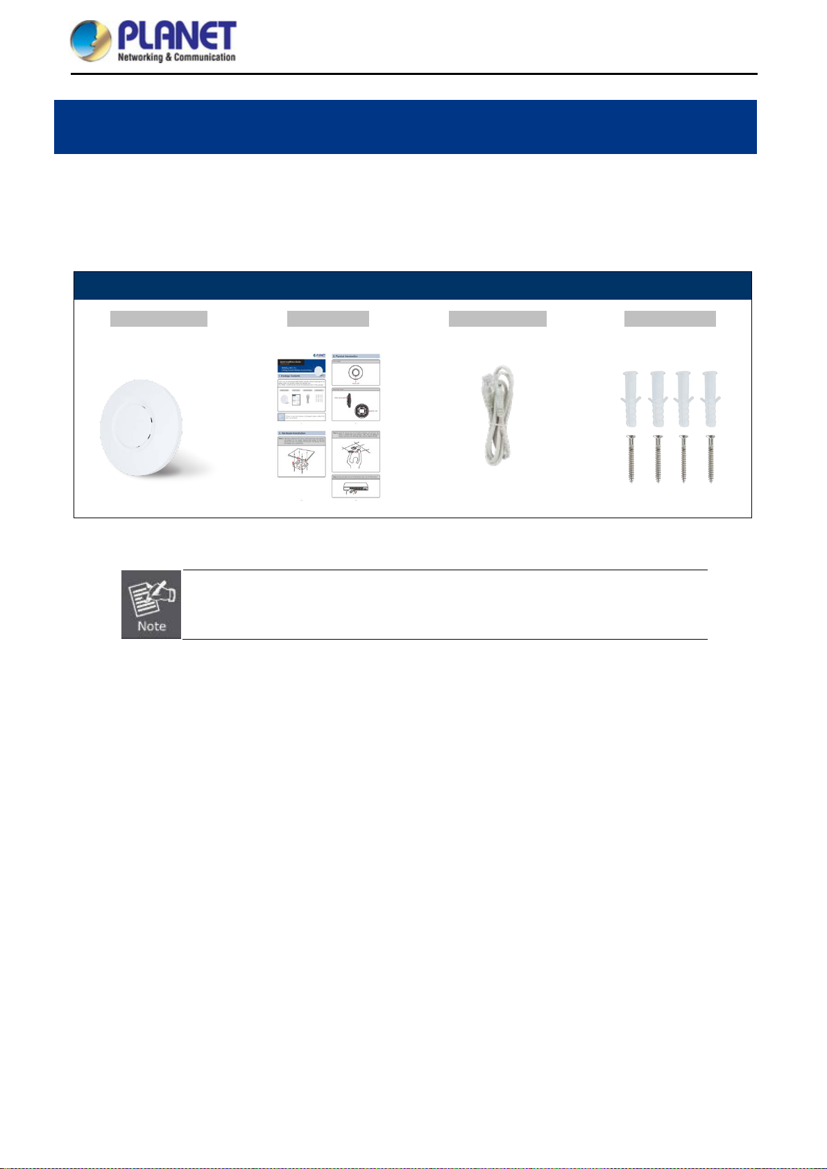
Package Contents 1.1
Thank you for choosing PLANET WNAP-C3220E W ireless AP. Please verify the contents inside the package
box.
Package Contents of WNAP-C3220E
WNAP-C3220E Quick Guide Ethernet Cable Mounting Kit
If there is any item missing or damaged, please contact the seller immediately.
-1-
Page 10
User Manual of WNAP-C3220E
Product Description 1.2
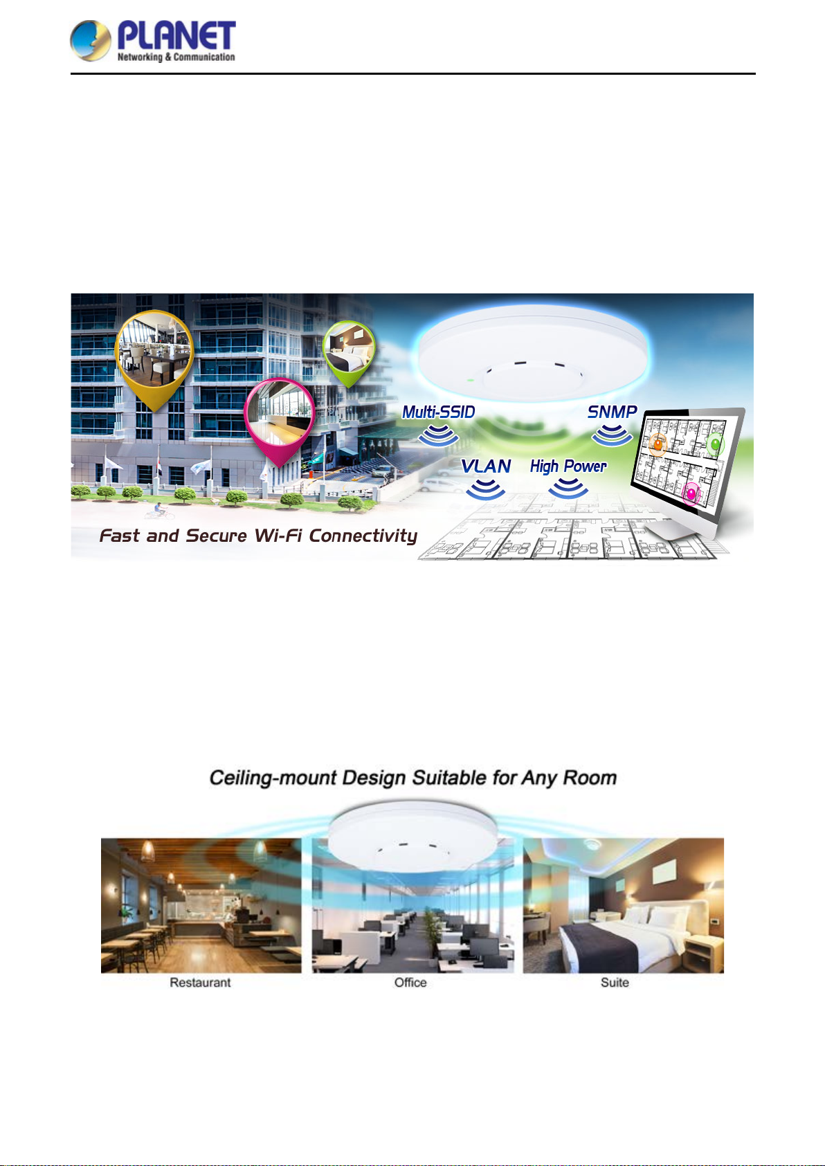
Centrally-Managed Wireless Network for Enterprises
PLANET WNAP-C3220E 300Mbps 802.11n Wireless Access Point offers high p ower and user l im itation cont rol
that can extend your wireless network coverage and manage clients easily. With 802.1Q VLAN and PLANET AP
Controller complianc e, the WNAP-C3220E can help cr eate a sec ur e, cos t -effec tiv e and h ighly-scalable wireless
LAN infrastructure that provides a seamlessly and centrally managed wireless network.
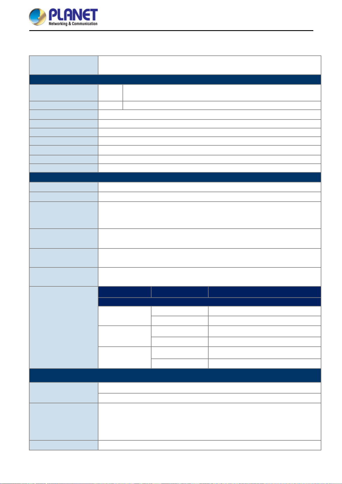
Wireless Range Extender
To ext end the coverage and eliminate the dead spot of wireless network in every place, the WNAP-C3220E
supports Universal Repeater mode which can solve the incompatibility between brands and provides a
high-speed, wide coverage. The space-saving and ceiling-mountable design makes the WNAP-C3220E
exquisite and easy to be mounted on the c e ilin g or wal l in different places. The bu ilt -i n inte l ligent 5dBi high-gain
antennas offer 360 degrees of wider coverage with excellent performance.
-2-
Page 11

User Manual of WNAP-C3220E
Advanced, Secure and Rigorous Authentication
The WNAP-C 3220E supports 128-bit WEP, WPA / WPA2, W PA-PSK and W PA2-PSK wireless encryptions, the
advanced WPA2-AES mechanism and 802.1X RADIUS authentication, which can effectively prevent
eavesdropping by unauthorized users or bandwidth occupied by unauthenticated wireless access. Furthermore,
any users are granted or denied access to the wireless LAN n etwork based on the ACL (Access Control List)
that the administrator pre-established. For m anagement purposes, the IEEE 802.1Q VLAN suppor ted allows
multiple VLAN tags to be mapped to multiple SSIDs to distinguish the wireless access.
Flexible Deployment with PoE Feature
Compliant with IEEE 802.3af/at Power over Ethernet standard, the WNAP-C3220E can be powered and
networked by a s ingle UT P cable. It thus red uces the needs of extra cables and ded icated elec trical outlets on
the wall, ceiling or any other place which is difficult to reach. The wireless AP deployment becomes more flexible
and worry-free from the power outlet locations.
-3-
Page 12
User Manual of WNAP-C3220E
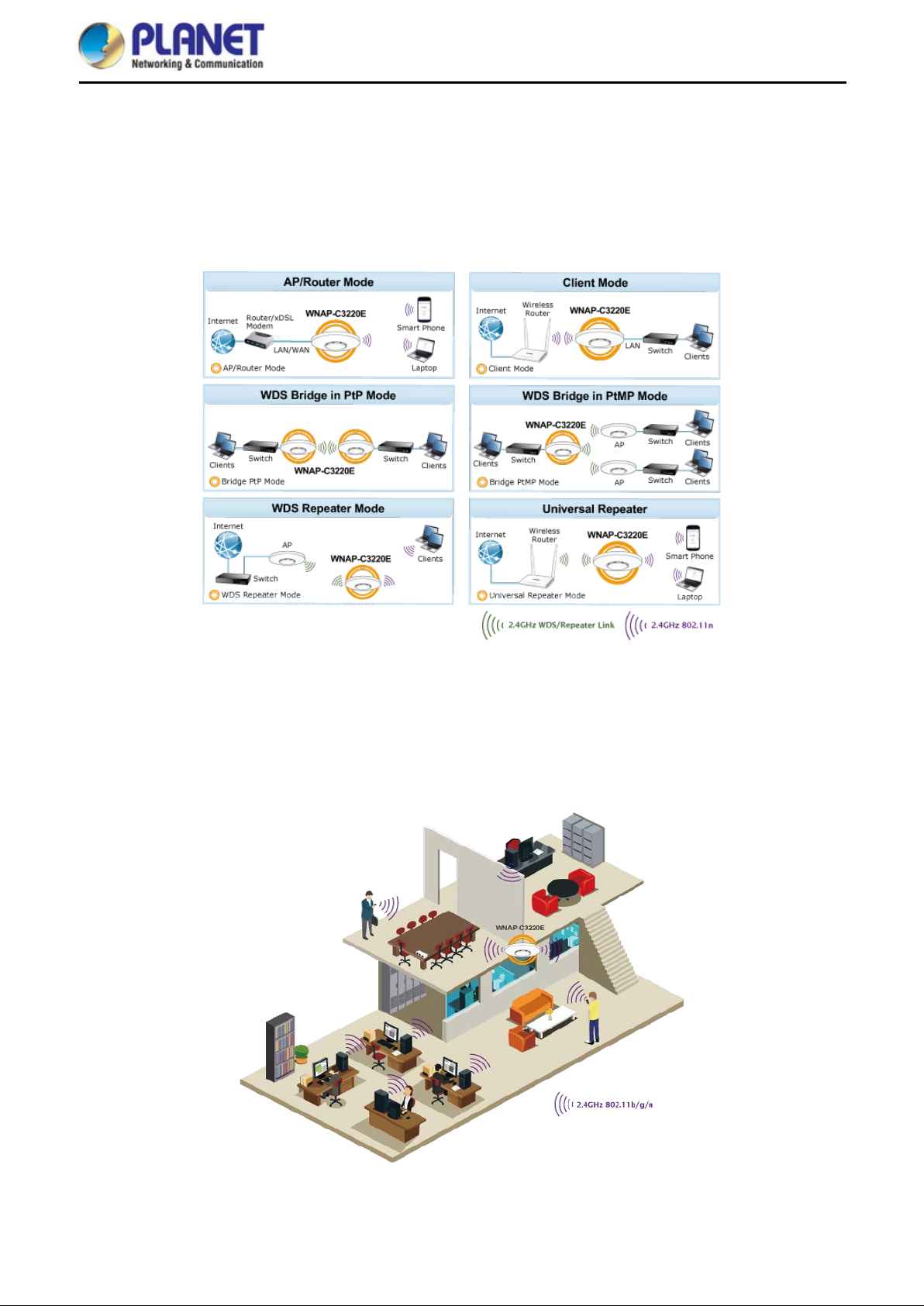
Comprehensive Wireless Operation Mode
The WNAP-C3220E supports multiple types of wireless connectivity such as AP, Gateway, Repeater, WDS
Point-to-Point (PtP) and WDS Point-to-Multipoint (PtMP), allowing users to comprehensively experience various
applications. It also helps users to easily build wirele ss network and extend the wireless r ange of the existing
wireless network.
Easy Installation and Management
With user-friendl y Web UI and s tep-by-step Quick Setup Wizard, th e W NAP-C32 00E is easy to inst all, even for
users who never exp erience setting up a wireless network . Furthermore, simpl y install our software contr oller,
PLANET SAPC (Smar t AP Contro l), to de liver wireles s prof iles to m ultiple APs s im ultaneousl y, thus making the
central management simple.
-4-
Page 13

User Manual of WNAP-C3220E
Product Features 1.3
Wireless Standard Compliance
Compliant with IEEE 802.11n wireless technology with data rate of up to 300Mbps
Backward compatible with 802.11b/g standard
Supports IEEE 802.3af/at standard-based PoE
Secure Network Connection
Advanced security: 64-/128-bit WEP, WPA/WPA2 and WPA-PSK/WPA2-PSK (TKIP/AES
encryption), 802.1x
Supports wireless MAC address filtering control to limit the connected wireless clients
Supports 802.1Q VLAN and SSID-to-VLAN mapping
Supports IP/Port/MAC address/URL filtering, DoS, SPI Firewall
Supports DMZ and port forwarding
Bandwidth control per IP address to increase network stability
Multiple Operation Modes and Wireless Features
Multiple operation modes: AP, Gateway, Repeater, WDS
WMM (Wi-Fi multimedia) provides higher priority to multimedia transmitting over wireless
Coverage threshold to limit the weak signal of clients occupying session
Real-time Wi-Fi channel analysis chart and client limit control for better performance
Easy Deployment and Management
Supports PLANET AP Controllers in AP mode
Easy discovery by PLANET Smart Discovery
Self-healing mechanism through system auto reboot setting
System status monitoring through remote Syslog Server
Supports PLANET DDNS/ Easy DDNS
-5-
Page 14
User Manual of WNAP-C3220E
Hardware Specifications
Antennas
Button
LED Indicators
Dimensions (Φ x H)
Weight
Power Consumption
Mounting
Wireless Interface Specifications
Standard
QAM, DBPSK, DQPSK,
2.4GHz
Channel Width
Product Specifications 1.4
Product
WDAP-C3220E
300Mbps 802.11n Ceiling-mount Wireless Access Point
Interfaces LAN
Gain: 2 x 5dBi antenna
Reset button (Press over 7 seconds to reset the device to the factory default)
Power
159 x 45mm
161 ±5g
Power Requirements
48V 0.5A, IEEE 802.3af/at PoE+
< 5W
Ceiling mount
IEEE 802.11b/g/n 2.4GHz
Media Access Control
CSMA/CA
Transmission/emission type: DSSS/OFDM
Data Modulation
Data modulation type: OFDM: BPSK, QPSK, 16-QAM, 64CCK
1 x 10/100BASE-TX RJ45 port
Auto-negotiation and auto MDI/MDI-X
Frequency Range
Operating Channels
RF Power
Receive Sensitivity
Software Features
LAN
FCC: 2.412~2.462GHz
ETSI: 2.412~2.472GHz
FCC: 1~11
ETSI: 1~13
FCC: up to 25 ± 1.5dBm
ETSI: <20dBm (EIRP)
Network Mode Data Rate Receive Sensitivity (dBm)
1Mbps -95
802.11b
11Mbps -90
6Mbps -92
802.11g
54Mbps -72
MCS0/MCS8 -92
802.11n
MCS7/MCS15 -70
Static IP
Supports IP MAC binding
Wireless Mode
Access Point
Gateway
Repeater
WDS (AP/Bridge/Station)
20MHz, 40MHz,
-6-
Page 15

User Manual of WNAP-C3220E
Encryption Security
Wireless Security
Max. SSIDs
Max. Clients
Max. WDS Peers
Wireless QoS
Wireless Advanced
Status Monitoring
64-/128-bit WEP, WPA, WPA-PSK, WPA2, WP A2-PSK, 802.1X
Enable/Disable SSID Broadcast
Wireless MAC address filtering
User Isolation
4
64 per radio (50 is suggested, depending on usage)
4
Supports Wi-Fi Multimedia (WMM)
Auto channel selection
5-level transmit power control (100%, 75%, 50%, 25%, 12.5%)
Client limit control, coverage threshold
Wi-Fi channel analysis chart
Fast Roaming
Device status, wireless client L ist
PLANET Smart Discovery
DHCP client table
System Log supports remote syslog server
VLAN
Self-healing
IEEE 802.1Q VLAN (VID: 3~4094)
SSID-to-VLAN mapping to up to 4 SSIDs
Supports auto reboot settings per day/hour
Supports PLANET Hardware AP Controller/ Software AP Controller
Applicable controllers
Remote management through PLANET DDNS/Easy DDNS
Configuration backup and restore
[1]
: WAPC-500, SAPC
System Management
Supports UPnP
Supports IGMP Proxy
Supports PPTP/L2TP/IPSec VPN pass-through
SNMP v1/v2c/v3 support, MIB I/II, Private MIB
Remarks 1. ^ the feature will be supported through firmware/system upgrade.
Environment & Certification
Temperature
Humidity
Operating: 0 ~ 40 degrees C
Storage: -40 ~ 70 degrees C
Operating: 10 ~ 90% (non-condensing)
Storage: 5 ~ 90% (non-condensing)
Regulatory
CE, RoHS
-7-
Page 16
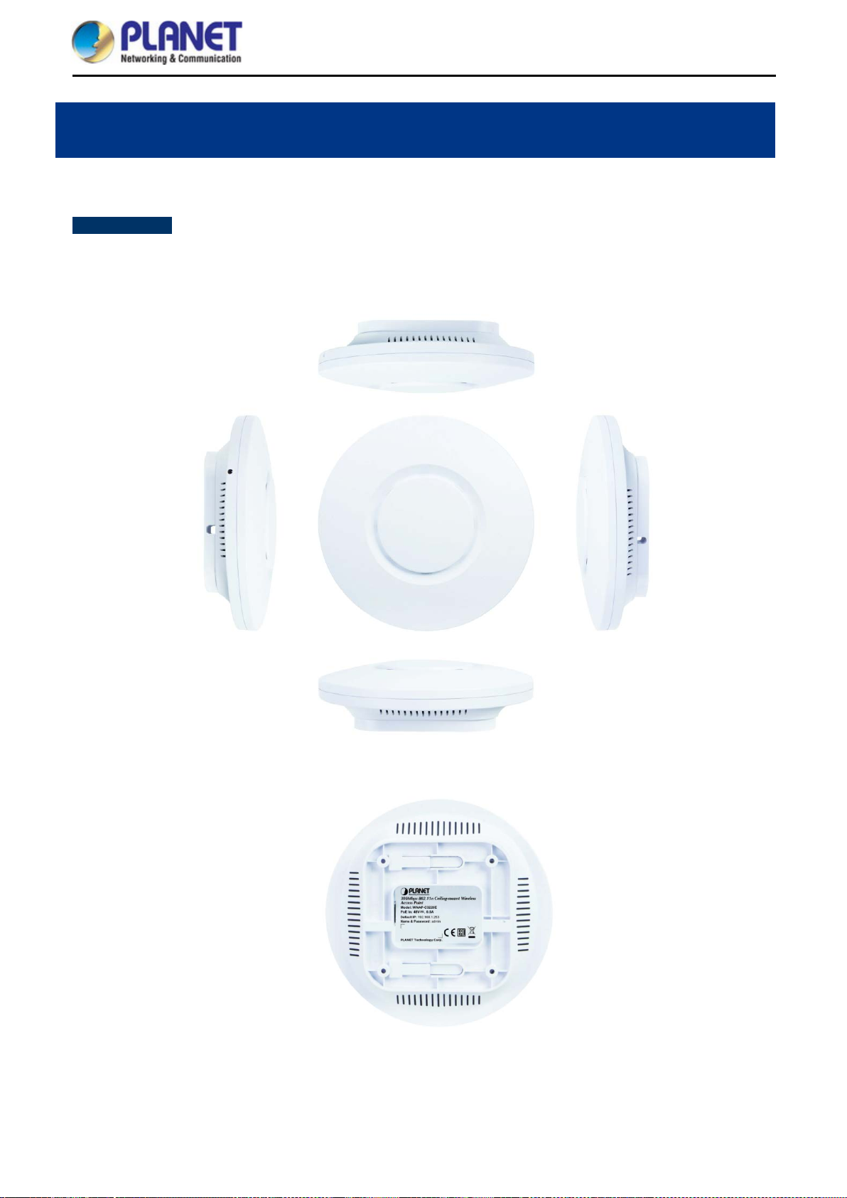
Product Outlook 2.1
WNAP-C3220E
Dimensions: 159 x 45mm
Weight: 161 ±5g
Triple View
User Manual of WNAP-C3220E
Chapter 2. Hardware Installation
Figure 2-1 WNAP-C3220E Triple View
-8-
Page 17
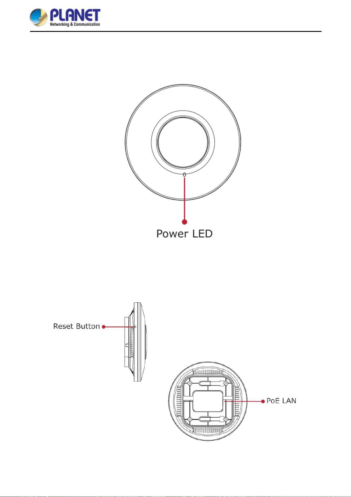
Front Panel
User Manual of WNAP-C3220E
Rear Panel
Figure 2-2 WNAP-C3220E Front Panel
Figure 2-3 WNAP-C3220E Rear Panel
-9-
Page 18
User Manual of WNAP-C3220E
Chapter 3. Connecting to the AP
System Requirements 3.1
Broadband Internet Access Service (Cable/xDSL/Ethernet connection)
One IEEE 802.3at PoE switch (supply power to the WNAP-C3220E)
PCs with a working Ethernet adapter and an Ethernet cable with RJ45 connectors
PCs running Windows 98/ME, NT4.0, 2000/XP, Windows Vista / Win 7, MAC OS 9 or later, Linux,
UNIX or other platforms compatible with TCP/IP protocols
1. The AP in the following instructions refers to PLANET WNAP-C3220E.
2. It is recommended to use Internet Explorer 11, Firefox or Chrome to access the AP.
Installing the AP 3.2
Before installing the AP, mak e s ure your Po E switch is connected to the Internet t h r ough the broadband serv ice
successfully at this moment. If there is any problem, please contact your local ISP.
Please install the AP acc ording to the following steps. Don't forget to pul l out the power plug and keep your
hands dry.
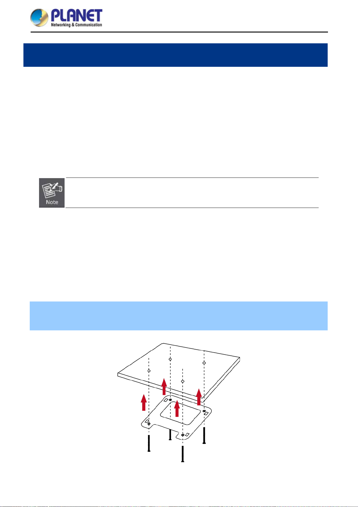
Step 1. Place the brac ket on t he wall or cei ling and m ark each point in the brack et for the sc rews. R emove th e
bracket to drill the points and insert the plastic wall-m ounts. Use s crews to lock the bracket b y a screw
driver.
Figure 3-1 Fix it with the screws
-10-
Page 19
User Manual of WNAP-C3220E
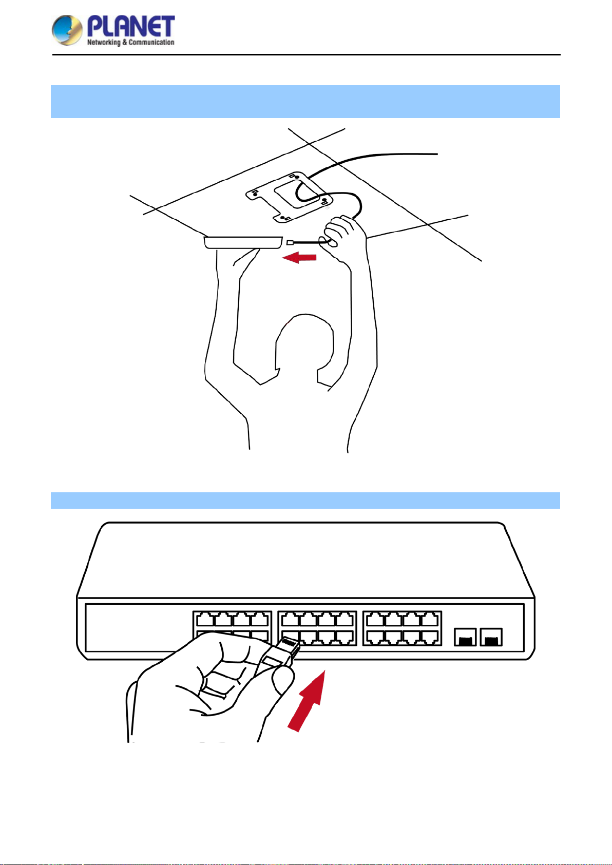
Step 2. Load the device into the mounting bracket, and be sure the device is mated with fixed screws. Then, lock
the device in position and plug the Ethernet cable into the WNAP-C3220E.
Figure 3-2 Connect the Ethernet cable
Step 3. Plug the other end of the Ethernet cable into the PoE switch.
Figure 3-3 Connect the PoE injector
-11-
Page 20

User Manual of WNAP-C3220E
Chapter 4. Quick Installation Guide
This chapter will show you how to configure the basic functions of your AP within minutes.
A computer with wired Ethernet connection to th e Wireless AP is required for the first-time
configuration.
Manual Network Setup -- TCP/IP Configuration 4.1
The default IP address of t he WNAP-C3220E is 192.168.1.253. And the default Subnet Mas k is 255.25 5.255 .0.
These values can be changed as you want. In this guide, we use all the default values for description.
Connect the WNAP-C3220E with your PC by an Ether net cable plugging in LAN por t on one side and in LAN
port of PC on the other side. Please power on the WNAP-C3220E by PoE switch through the PoE port.
In the following sections, we’ll introduce how to install and conf igure the T CP/IP correctly in Windows 10. And
the procedures in other oper ating systems are sim ilar. First, make sure your Ethernet A dapter is working, and
refer to the Ethernet adapter manual if needed.
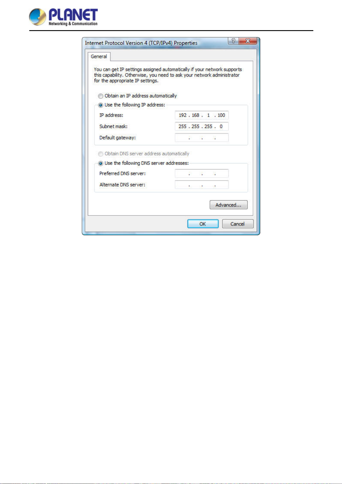
4.1.1 Configuring the IP Address Manually
Summary:
Set up the TCP/IP Protocol for your PC.
Configure the network parameters . The IP address is 192.168.1.xxx (If the d efault IP address of the
WNAP-C3220E is 192.168.1.253, and the DSL router is 192.1 68.1.254, the "xxx" can be conf igured to
any number from 1 to 252.) and subnet mask is 255.255.255.0.
1 Select Use the following IP address, and then configure the IP address of the PC.
2 For example, as the default IP address of the WNAP-C3220E is 192.168.1.253 and the DSL router is
192.168.1.254, you may choose from 192.168.1.1 to 192.168.1.252.
-12-
Page 21
User Manual of WNAP-C3220E
Figure 4-1 TCP/IP Setting
Now click OK to save your settings.
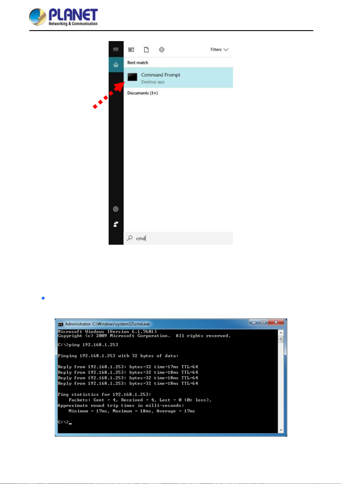
Now, you can run the ping comm and in the command prompt to verify the network connection between your
PC and the AP. The following example is in Windows 10 OS. Please follow the steps below:
1. Click on Start > Run.
2. Type “cmd” in the Search box.
-13-
Page 22
User Manual of WNAP-C3220E
Figure 4-2 Windows Start Menu
3. Open a command prompt, type ping 192.168.1.253 and then press Enter.
If the result displayed is sim ilar to Figure 4-3, it means the connection bet ween your PC and th e AP
has been established well.
Figure 4-3 Successful Result of Ping Command
-14-
Page 23

User Manual of WNAP-C3220E
If the result displayed is sim ilar to Figure 4-4, it means the c onnection between your PC and the AP
has failed.
Figure 4-4 Failed Result of Ping Command
If the address is 0.0.0 .0, check your adapt er installation, sec urity settings, and the settings on your AP. Som e
firewall software programs may block a DHCP request on newly installed adapters.
-15-
Page 24
User Manual of WNAP-C3220E
n the screen that
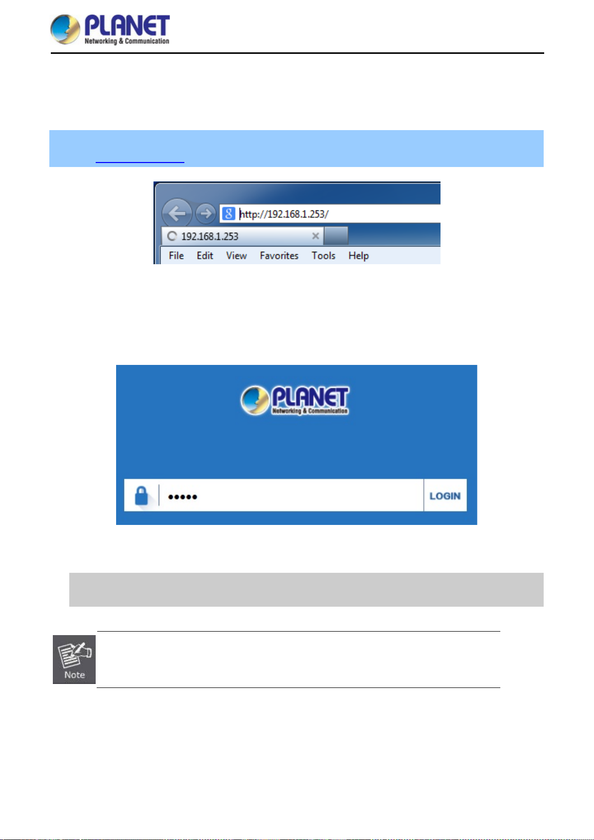
Starting Setup in the Web UI 4.2
It is easy to configure and manage the AP with the web browser.
Step 1. To access the configuration utility, open a web-browser and enter the default IP address
http://192.168.1.253 in the web address field of the browser.
Figure 4-5 Login by Default IP Address
After a moment, a login window will appear. Enter admin for the password in lower case letters. T hen click
LOGIN or press the Enter key.
Default IP Address: 192.168.1.253
Default Password: admin
Figure 4-6 Login Window
If the above screen does not pop up, it may mean that your web-browser has been set to a
proxy. Go to Tools menu> Internet Options> Connections> LAN Settings o
appears, uncheck Using Proxy and click OK to finish it.
-16-
Page 25

User Manual of WNAP-C3220E
Chapter 5. Configuring the AP
This chapter deliver s a detailed pres entation of AP’s functionalities and features 3 main items below, allowing
you to manage the AP with ease. The screenshots use the WNAP-C3220E as an example.
The page includes the following fields:
Object Description
2.4G Wireless Settings
LAN Settings
AP Position Settings
Enter the 2.4G wireless settings to enable or disable wireless LAN.
Enter the LAN settings to change the LAN IP address.
Configure the AP name and Location.
Figure 5-1 Main Menu
-17-
Page 26

User Manual of WNAP-C3220E
Wizard 5.1
The Wizard guides you to configuring the WNAP-C3220E in a different mode, including Gateway, Repeater,
AP and Super WDS mode.
Figure 5-2 Operation Mode
The default operation mode is AP Mode.
-18-
Page 27

User Manual of WNAP-C3220E
Gateway Mode (Router) 5.2
Click “Wizard” “Gateway Mode” and the following page will be displayed. This section allows you to configure
the Gateway mode.
Figure 5-3 Gateway Mode
-19-
Page 28

User Manual of WNAP-C3220E
5.2.1 WAN Settings
Static IP
If your ISP offers you static IP Internet connection t ype, select “Static IP" and then en ter IP address, subnet
mask, default gateway and primary DNS information provided by your ISP in the corresponding fields.
Figure 5-4 Gateway -- Static IP
The page includes the following fields:
Object Description
IP Address
Enter the WAN IP address provide d b y your I SP. Enquire your ISP if you
are not clear.
Subnet Mask
Default Gateway
Primary DNS
Enter WAN Subnet Mask provided by your ISP.
Enter the WAN Gateway address provided by your ISP.
Enter the necessary DNS address provided by your ISP.
PPPoE (ADSL)
Select PPPOE if your ISP is using a PPPo E connect ion and pr ovide you with PP PoE user name and password
info.
Figure 5-5 Gateway – PPPoE (ADSL)
The page includes the following fields:
Object Description
PPPoE Name
PPPoE Password
Enter the user name provided by your ISP.
Enter the password provided by your ISP.
-20-
Page 29

User Manual of WNAP-C3220E
DHCP
Choose “DHCP” and th e router will autom atically obtain IP addresses, subnet masks and gateway addresses
from your ISP.
Figure 5-6 Gateway – DHCP
5.2.2 Wireless
Figure 5-7 Gateway – Wireless
The page includes the following fields:
Object Description
WLAN Status Select ON or OFF to enable or disable wireless LAN.
Wireless Analyzer
SSID
Channel
Press the button to check your wireless environment.
It is the wireless network name. The default SSID is PLANET_2.4G.
Select the operating channel you would like to use. The channel
range will be changed by selecting a different domain.
Encryption Select the wireless encryption. The default is None.
-21-
Page 30

User Manual of WNAP-C3220E
Repeater Mode (Universal Repeater) 5.3
Click “Wizard” “Repeater Mode” and the following page will be displayed. This section allows you to
configure the Repeater mode.
Figure 5-8 Repeater Mode
-22-
Page 31

User Manual of WNAP-C3220E
The page includes the following fields:
Object Description
Repeater SSID Enter the root AP’s SSID or press “Scan AP” to select.
Lockmac
Authentication
Check to lock the root AP MAC address.
Select the wireless encryption of root AP.
Bandwidth Select the operating channel width, “20MHz” or “40MHz”.
WDS Passthrough
Check to enable WDS passthrough if the root AP is the same model as client.
Press Scan AP to show the root AP that you need to repeat and press Choice to select the AP.
Figure 5-9 Repeater Mode -- Scan AP
-23-
Page 32

User Manual of WNAP-C3220E
Select the authentication and bandwidth which are the same as root AP to establish the connection.
Figure 5-10 Repeater Mode -- Select AP
-24-
Page 33

User Manual of WNAP-C3220E
AP Mode 5.4
In the AP mode, the AP wireless interface and cable interface bridge together. Click “Wizard” “AP Mode” and
the following page will be displayed. This section allows you to configure the AP mode.
Figure 5-111 AP Mode
-25-
Page 34

User Manual of WNAP-C3220E
The page includes the following fields:
Object Description
WLAN Select “ON” or “OFF” to enable or disable 2.4G or 5.8G wireless LAN.
Wireless Analyzer
Status SSID
Channel
Press the button to check your wireless environment.
It is the wireless network name. The default SSID is “PLANET_2.4G”.
Select the operating channel you would like to use. The channel range will be
changed by selecting a different domain.
Encryption Select the wireless encryption. The default is “None”.
AP Name
AP Location
Enter the name of AP.
Enter the location of AP.
Enter the LAN IP address.
Figure 5-12 AP Mode -- LAN
-26-
Page 35

User Manual of WNAP-C3220E
Super WDS Mode (WDS Bridge in PtP/PtMP) 5.5
In the Super WDS mode, the wireless interface can be connected with other wireless APs through WDS, and the
wireless interface and ca ble interface. Click “Wizard” “Super WDS Mode” and the following page will be
displayed. This section allows you to configure the AP mode.
-27-
Page 36

User Manual of WNAP-C3220E
Figure 5-13 Super WDS Mode
The page includes the following fields:
Object Description
2.4GHz WLAN Select “ON” or “OFF” to enable or disable 2.4G wireless LAN.
Status SSID
Channel
It is the wireless network name. The default SSID is “PLANET_2.4G”.
Select the operating channel you would like to use. The channel range will be
changed by selecting a different domain.
Encryption Select the wireless encryption. The default is “None”.
-28-
Page 37

User Manual of WNAP-C3220E
AP1 enters the MAC a ddr e s s of AP2. A nd A P2 e nter s the MAC address of AP1. Then select the sam e Chann el
to establish the connection.
Figure 5-14 Super WDS Mode – AP1
Figure 5-155 Super WDS Mode – AP2
The page includes the following fields:
Object Description
SSID
It is the wireless network name. The default SSID is “PLANET_2.4G”.
Bandwidth Select the operating channel width, “20MHz” or “40MHz”.
Channel
Select the operating channel you would like to use. The channel range will be changed by
selecting a different domain.
MAC
Enter the MAC address of slave AP.
Encryption Select the wireless encryption. The default is “Open”.
-29-
Page 38

Advanced 5.6
5.6.1 Device Status
5.6.1.1. Status
User Manual of WNAP-C3220E
Figure 5-166 Advanced
The page includes the following fields:
Object Description
Software Version
Hardware Version
Uptime
It shows the firmware version of AP.
It shows the hardware version of AP.
It shows the AP uptime.
Figure 5-177 Status
-30-
Page 39

5.6.1.2. 2.4G Status
User Manual of WNAP-C3220E
Figure 5-188 Wireless Status
The page includes the following fields:
Object Description
2.4G / 5.8G Wireless Status It shows the wireless status is Enable or Disable.
SSID It shows the SSID of the AP. Default is PLANET_2.4G.
MAC
Channel
Encryption
Connected Users
It shows the MAC address of the AP.
It shows the channel of the AP. Default 2.4GHz is channel 6.
It shows the wireless encryption.
It shows the wireless connected users.
5.6.1.3. LAN Status
Figure 5-19 LAN Status
-31-
Page 40

The page includes the following fields:
Object Description
LAN IP It shows the IP of the AP. Default is 192.168.1.253.
Subnet Mask It shows the subnet mask of the AP. Default is 255.255.255.0.
User Manual of WNAP-C3220E
MAC
5.6.2 Wireless
5.6.2.1. Basic Settings
It shows the MAC address of the LAN por.t
The page includes the following fields:
Object Description
Wireless Status It shows the wireless status is Enable or Disable.
SSID It shows the SSID of the AP. Default is PLANET_2.4G.
Broadcast SSID Select Enable or Disable the SSID.
WMM
It supports Wi-Fi multimedia and default is enabled.
Bandwidth It displays operating channel width which is 20MHz or 40MHz.
Channel It shows the channel of the AP. Default 2.4GHz is Channel 6.
Encryption
It shows the wireless encryption.
Figure 5-20 Basic Settings
-32-
Page 41

5.6.2.2. Virtual AP
User Manual of WNAP-C3220E
The page includes the following fields:
Object Description
Wireless Status It shows the wireless status is ON or OFF.
SSID It shows the SSID of the AP. Default is PLANET_2.4G_1.
Broadcast SSID Select Enable or Disable the SSID.
WMM
Encryption
It supports Wi-Fi multimedia and default is enabled.
It shows the wireless encryption.
5.6.2.3. Access Control
Figure 5-21 Virtual AP
Figure 5-22 Access Control - Access All
-33-
Page 42

User Manual of WNAP-C3220E
Figure 5-23 Access Control – Allow Listed
The page includes the following fields:
Object Description
Access Control Select MAC Access All, Allow Listed or Deny Listed.
MAC
Clear
Enter the MAC address that you need to allow or deny access.
Delete the MAC address that you select.
5.6.2.4. Advanced Settings
Figure 5-244 Advanced Settings
-34-
Page 43

User Manual of WNAP-C3220E
sions do not
The page includes the following fields:
Object Description
Regional It shows FCC or ETSI depending on the firmware.
Mode Select 802.11N/G or 802.11B/G in 2.4G AP.
RF Output Power The range of transm it power is 100%, 75%, 50%, 25% or 12.5%. In
case of shortening the distance and the coverage of the wireless
network, input a smaller value to reduce the radio transmission power.
Packet Threshold
When the length of a d ata packet exceeds this value, the ro uter will
send an RTS frame to the des tin ation wireless node, and t he l atter w ill
reply with a CTS f rame, and thus the y are rea d y to comm unicate. T he
default value is 2346.
Beacon interval
Set beacon interval, the value range is f rom 100 to 1024. The default
value is 100.
Maximum Users The maximum users are 64.
Coverage Threshold
The coverage threshol d is t o lim it the we ak s ignal of clients occupying
session. The default is -90dBm.
Distance
Aggregation
Select a specified distance of the two nodes.
A part of the 802.11n standard that allows sending multiple frames per
single access to the medium by combining fram es together into one
larger frame. It creates the larger frame b y combining smaller fr ames
with the same physical source, destination end points, and traffic class
(QoS) into one large frame with a common MAC header.
Short GI
Guard intervals are used to ensure that distinct transmis
interfere with one another.
User Isolation
Enable it to isolate each c onnecte d wireless client so that they cannot
access mutually.
-35-
Page 44

5.6.3 Network
5.6.3.1. LAN Settings
The page includes the following fields:
User Manual of WNAP-C3220E
Figure 5-25 LAN Settings
Object Description
IP
Subnet Mask
5.6.3.2. VLAN
Enter an IP address of LAN.
Enter a subnet mask of LAN.
The page includes the following fields:
Object Description
VLAN ID
AP
Enter the VLAN ID from 3 to 4094.
Select AP or VAP included in the VLAN.
Figure 5-26 VLAN
-36-
Page 45

User Manual of WNAP-C3220E
5.6.3.3. SNMP
Figure 5-27 SNMP
The page includes the following fields:
Object Description
Read Community Enter the read community, default is public
Write Community Enter the write community, default is private
Trap Destination Address Enter the SNMP trap IP address, default is 192.168.1.1
5.6.4 Management
5.6.4.1. System Time
The page includes the following fields:
Figure 5-28 Sy st e m Time
Object Description
System Time
Auto Restart
It shows the system time
Select the time that you want to reboot
-37-
Page 46

5.6.4.2. Signal Tracking
The page includes the following fields:
User Manual of WNAP-C3220E
Object Description
SSID
MAC
Signal Strength
Select the SSID you need to check by pressing the Scan AP button
It shows the MAC address of the tracked AP
It shows the signal strength of the AP
5.6.4.3. Logs
Figure 5-29 Logs
-38-
Page 47

The page includes the following fields:
Object Description
User Manual of WNAP-C3220E
Remote Log Server
IP
Refresh
Clear
5.6.4.4. Upgrade Firmware
Enable remote log server
Enter the IP of remote log server
Press to refresh the system log
Press to clear the system log
Figure 5-30 Upgrade Firmware
The page includes the following fields:
Object Description
Choose File
Upgrade
Restore Factory Settings
Press to select the firmware file
Press to upgrade the firmware
Select to reset the device to default when upgrading firmware
-39-
Page 48

5.6.4.5. System
User Manual of WNAP-C3220E
Figure 5-311 System
The page includes the following fields:
Object Description
Backup
Choose File
Restore
Reset Default
Reboot
Press to back up the configuration
Press to select the configuration file
Press to restore the configuration
Press to reset the device to default
Press to reboot the device
-40-
Page 49

5.6.4.6. User
User Manual of WNAP-C3220E
Figure 5-32 User
The page includes the following fields:
Object Description
Old Password
Password
Confirm Password
Enter the old password
Enter the new password
Enter the new password again
-41-
Page 50

User Manual of WNAP-C3220E
Chapter 6. Quick Connection to a Wireless Network
In the following sections, the default SSID of the WNAP-C3220E is configured to “default”.
Windows XP (Wireless Zero Configuration) 6.1
Step 1: Right-click on the wireless network icon displayed in the system tray
Figure 6-1 System Tray – Wireless Network Icon
Step 2: Select [View Available Wireless Networks]
Step 3: Highlight and select the wireless network (SSID) to connect
(1) Select S SI D [default]
(2) Click the [Connect] button
Figure 6-2 Choosing a Wireless Network
-42-
Page 51

Step 4: Enter the encryption key of the wireless AP
ake
(1) The Wireless Network Connection box will appear
(2) Enter the encryption key that is configured in section 5.7.2.1
(3) Click the [Connect] button
Figure 6-3 Entering the Network Key
User Manual of WNAP-C3220E
Step 5: Check if “Connected” is displayed
Figure 6-4 Choosing a Wireless Network -- Connected
Some laptops are equipped with a “Wireless ON/OF F” switch for the interna l wireless LAN. M
sure the hardware wireless switch is switched to “ON” position.
-43-
Page 52

User Manual of WNAP-C3220E
Windows 7 (WLAN AutoConfig) 6.2
WLAN AutoConfig s ervice i s built-i n in W indows 7 that can be use d to detec t and connect t o wirel ess net work .
This built-in wireless network connection tool is similar to wireless zero configuration tool in Windows XP.
Step 1: Right-click on the network icon displayed in the system tray
Figure 6-5 Network Icon
Step 2: Highlight and select the wireless network (SSID) to connect
(1) Select SSID [default]
(2) Click the [Connect] button
Figure 6-6 WLAN AutoConfig
If you will be connecting to this Wireless AP in the future, check [Connect automatically].
-44-
Page 53

Step 4: Enter the encryption key of the wireless AP
(1) The Connect to a Network box will appear.
(2) Enter the encryption key that is configured in section 5.7.2.1
(3) Click the [OK] button.
User Manual of WNAP-C3220E
Figure 6-7 Typing the Network Key
Figure 6-8 Connecting to a Network
-45-
Page 54

Step 5: Check if “Connected” is displayed.
User Manual of WNAP-C3220E
Figure 6-9 Connected to a Network
-46-
Page 55

User Manual of WNAP-C3220E
Mac OS X 10.x 6.3
In the following sections, the default SSID of the WNAP-C3220E is configured to “default”.
Step 1: Right-click on the network icon displayed in the system tray
The AirPort Network Connection menu will appear.
Figure 6-10 Mac OS – Network Icon
Step 2: Highlight and select the wireless network (SSID) to connect
(1) Select and SSID [default].
(2) Double-click on the selected SSID.
Figure 6-11 Highlighting and Selecting the Wireless Network
-47-
Page 56

Step 4: Enter the encryption key of the wireless AP
Remember this
(1) Enter the encryption key that is configured in section 5.7.2.1
(2) Click the [OK] button.
User Manual of WNAP-C3220E
If you will be connecting to this Wireless AP in the future, chec k [
network].
Figure 6-12 Enter the Password
-48-
Page 57

Step 5: Check if the AirPort is connected to the selected wireless network.
If “Yes”, then there will be a “check” symbol in front of the SSID.
User Manual of WNAP-C3220E
Figure 6-13 Connected to the Network
-49-
Page 58

User Manual of WNAP-C3220E
There is another way to configure the MAC OS X wireless settings:
Step 1: Click and open the [System Preferences] by going to Apple > System Preference or Applications
Figure 6-14 System Preferences
Step 2: Open Network Preference by clicking on the [Network] icon
Figure 6-15 System Preferences -- Network
-50-
Page 59

Step 3: Check Wi-Fi setting and select the available wireles s networ k
(1) Choose the AirPort on the left menu (make sure it is ON)
(2) Select Network Name [default] here
If this is the first time to connect to the Wireless AP, it should show “No network selected”.
User Manual of WNAP-C3220E
Figure 6-16 Selecting the Wireless Network
-51-
Page 60

User Manual of WNAP-C3220E
iPhone/iPod Touch/iPad 6.4
In the following sections, the default SSID of the WNAP-C3220E is configured to “default”.
Step 1: Tap the [Settings] icon displayed in the home screen
Figure 6-17 iPhone – Settings icon
Step 2: Check Wi-Fi setting and select the available wireless network
(1) Tap [General] \ [Network]
(2) Tap [Wi-Fi]
If this is the first time to connect to the Wireless AP, it should show “Not Connec te d”.
Figure 6-18 Wi-Fi Setting
-52-
Page 61

User Manual of WNAP-C3220E
Figure 6-19 Wi-Fi Setting – Not Connected
Step 3: Tap the target wireless network (SSID) in “Choose a Network…”
(1) Turn on Wi-Fi by tapping “Wi-Fi”
(2) Select SSID [default]
Figure 6-20 Turning on Wi-Fi
-53-
Page 62

Step 4: Enter the encryption key of the Wireless AP
(1) The password input screen will be displayed.
(2) Enter the encryption key that is conf ig ured in section 5.7.2.1
(3) Tap the [Join] button.
User Manual of WNAP-C3220E
Figure 6-21 iPhone -- Entering the Pas sword
-54-
Page 63

Step 5: Check if the device is connected to the selected wireless network.
If “Yes”, then there will be a “check” symbol in front of the SSID.
User Manual of WNAP-C3220E
Figure 6-22 iPhone -- Connected to the Network
-55-
Page 64

User Manual of WNAP-C3220E
Appendix A: Planet Smart Discovery Utility
To easily lis t the WNAP-C3220E in your Ethernet environm ent, the Planet Smart Discov ery Utility is an ideal
solution.
The following installation instructions guide you to running the Planet Smart Discovery Utility.
Step 1: Deposit the Planet Smart Discovery Utility in administrator PC.
Step 2: Run this utility and the follo wing scr ee n appears.
Step 3: Press “Refresh” for the current connected devices in the discovery list as shown in the following
screen:
Step 3: Press “Connect to Device” and then the Web login screen appears.
The fields in white bac kground can be m odified directly and then you can apply the n ew
setting by clicking “Update Device”.
-56-
Page 65

Q1: How to Set Up the AP Client Connection
Topology:
User Manual of WNAP-C3220E
Appendix B: FAQs
Step 1. Use static IP in the PCs that are connected with AP-1(Site-1) and AP-2 (Site-2). In this case, Site-1 is
“192.168.1.100”, and Site-2 is “192.168.1.200”.
-57-
Page 66

User Manual of WNAP-C3220E
Step 2. In AP-2, change t he default IP to the same IP range but different from AP-1. I n this case, the IP is
changed to 192.168.1.252.
Step 3. In AP-1, go to “Wizard” to configure it to AP Mode. In AP-2, configure it to Repeater Mode.
AP-1
AP-2
Step 4. In AP-2, press Scan AP to search the AP-1. You can also enter the MAC address, SSID, encryption and
bandwidth if you know what they are.
-58-
Page 67

User Manual of WNAP-C3220E
Step 5. Click “Next” to finish the setting.
Step 6. Click “Device Status” to check connection status.
-59-
Page 68

User Manual of WNAP-C3220E
Step 7. Use command line tool to ping each other to ensure the link is successfully establ is hed .
From Site-1, ping 192.168.1.200; and in Site-2, ping 192.168.1.100.
Step 8. Configure the TCP/IP settings of Site-2 to “Obtain an IP address automatically”.
-60-
Page 69

User Manual of WNAP-C3220E
Step 9. Use command line tool to ping the DNS (e.g., Google) to ensure Site-2 can access internet through the
wireless connection.
The following hints should be noted:
1) The encryption method must be the same as that of both sites if configured.
2) Both sites should be Line-of-Sight.
-61-
Page 70

Q2: How to Set Up the WDS Connection
Topology:
User Manual of WNAP-C3220E
-62-
Page 71

User Manual of WNAP-C3220E
Step 1. Use static IP in the PCs that are connected with WNAP-C3220E-1 (Site-1) and WNAP-C3220E-2
(Site-2). In this case, Site-1 is “192.168.1.100”, and Site-2 is “192.168.1.200”.
-63-
Page 72

User Manual of WNAP-C3220E
Step 2. In AP-2, change t he default IP to the same IP range but different from AP-1. I n this case, the IP is
changed to 192.168.1.252.
Step 3. In both APs, go to “Wizard” to configure it in Super WDS Mode.
Step 4. Go to “ Wireless” and press Scan AP to search the other AP. Yo u can als o enter th e MAC ad dres s and
SSID if you know what they are.
-64-
Page 73

Step 5. Click “Apply” to finish the setting.
User Manual of WNAP-C3220E
Step 6. Click “Return home” to check WDS status.
-65-
Page 74

User Manual of WNAP-C3220E
Step 7. Use command line tool to ping each other to ensure the link is successfully established.
From Site-1, ping 192.168.1.200; and in Site-2, ping 192.168.1.100.
The following hints should be noted:
1) The encryption method must be the same as that of both sites if configured.
2) Both sites should be Line-of-Sight.
-66-
Page 75

User Manual of WNAP-C3220E
Appendix C: Troubleshooting
If yo u find the AP is workin g improperl y or stop responding to you, p lease read this troub leshooting f irst before
contacting the dealer for help. Some problems can be solved by yourself within a very short time.
Scenario Solution
The AP is not responding to
me when I want to access it
by Web browser.
I can’t get connected to the
Internet.
a. Please check the connection of the power cord and the
Ethernet cable of this AP. All cords and cables should be
correctly and firmly inserted into the AP.
b. If all LEDs on this AP are off, please check the status of
power adapter, and make sure it is correctly powered.
c. You must use the same IP address section which AP
uses.
d. Are you using MAC or IP address filter? Try to connect
the AP by another computer and see if it works; if not,
please reset the AP to the factory default settings by
pressing the ‘reset’ button for over 7 seconds.
e. Use the Smart Discovery Tool to see if you can find the
AP or not.
f. If you did a firmware upgrade and this happens, contact
your dealer of purchase for help.
g. If all the solutions above don’t work, contact the dealer
for help.
a. Go to ‘Status’ -> ‘Internet Connection’ menu on the router
connected to the AP , and check Internet connection
status.
b. Please be patient. Sometimes Internet is just that slow.
c. I f you’ve connected a computer to Internet directly
before, try to do that again, and check if you can get
connected to Internet with your computer directly
attached to the device provided by your Internet service
provider.
d. Check PPPoE / L2TP / PPTP user ID and password
entered in the router’s settings again.
e. Call your Internet service provider and check if there’s
something wrong with their service.
f. If you just can’t connect to one or more website, but you
can still use other internet services, please check
URL/Keyword filter.
g. Try to reset the AP and try again later.
h. Reset the device provided by your Internet service
provider, too.
-67-
Page 76

Scenario Solution
i. Try to use IP address instead of host name. If you can
use IP address to communicate with a remote server,
but can’t use host name, please check DNS setting.
I can’t locate my AP by my
wireless device.
a. ‘Broadcast ESSID’ set to off?
b. Both two antennas are properly secured.
c. Are you too far from your AP? Try to get closer.
d. Please remember that you have to input ESSID on your
wireless client manually, if ESSID broadcast is disabled.
File downloading is very slow
or breaks frequently.
a. Internet is slow sometimes. Please be patient.
b. Try to reset the AP and see if it’s better after that.
c. Try to know what computers do on your local network. If
someone’s transferring big files, other people will think
Internet is really slow.
d. If this never happens before, call you Internet service
provider to know if there is something wrong with their
network.
I can’t log into the web
management interface; the
password is wrong.
a. Make sure you’re connecting to the correct IP address of
the AP!
b. Password is case-sensitive. Make sure the ‘Caps Lock’
light is not illuminated.
c. If you really forget the password, do a hard reset.
The AP becomes hot
a. This is not a malfunction, if you can keep your hand on
the AP’s case.
b. If you smell something wrong or see the smoke coming
out from AP or A/C power adapter, please disconnect
the AP and power source from utility power (make sure
it’s safe before you’re doing this!), and call your dealer of
purchase for help.
User Manual of WNAP-C3220E
-68-
Page 77

User Manual of WNAP-C3220E
Appendix D: Glossary
802.11ac - 802.11ac is a wireless network ing standard in the 802.11 family (which is marketed under the
brand name Wi-Fi), developed in the IEEE Standards Assoc iation process, providin g
high-throughput
wireless local area networks (WLANs) on the 5 GHz band.
802.11n - 802.11n builds upon previous 802.11 standards by adding MIMO (multiple-input
multiple-outpu t). MIMO uses multiple transmitter and receiver antennas to allow for increase d data
throughput via spatia l multiplexing an d increased range by exploiting the spatia l diversity, perhaps
through coding schem es like Alamouti coding. The E nhanced Wireless Consortium (EWC) [3] was
formed to help accelerate the IEEE 802.11n development process and promote a technology
specification for interoperability of next-generation wireless local area networking (WLAN) products.
802.11a
- 802.11a was an am endment to the IEEE 802.11 wirel ess local network specif ications that
defined requirements for an orthogonal frequency division multiplexing (OFDM) communication
system. It was originally designed to support wireless communication in the unlicensed national
information infras tructure (U-N II) bands (in the 5–6 GHz frequ ency range) as regulated in the Un ited
States by the Code of Federal Regulations, Title 47, Section 15.407.
802.11b - The 802.11b s tandard specifies a wire less networking at 11 Mbps using direct-sequence
spread-spectrum (DSSS) t echnology and op erating in the unlicensed radi o spectrum at 2.4G Hz, and
WEP encryption for security. 802.11b networks are also referred to as Wi-Fi networks.
802.11g - specification for wireless networking at 54 Mbps using direct-sequence spread-spectrum
(DSSS) technology, using OFDM modulation and operating in the unlicensed radio spectrum at
2.4GHz, and backward compatibility with IEEE 802.11b devices, and WEP encryption for security.
DDNS (Dynamic Domain Name System) - The capability of assigning a fixed host and domain name to
a dynamic Internet IP Address.
DHCP (Dynamic Host Configuration Protocol) - A protocol that automatically configure the TCP/IP
parameters for the all the PC(s) that are connected to a DHCP server.
DMZ (Demilitarized Zone) - A Dem ilitarized Zone allows one loc al host to be exposed t o the Internet
for a special-purpose service such as Internet gaming or videoconferencing.
DNS (Domain Name System) - An Internet Service that translates the names of websites into IP
addresses.
Domain Name - A descriptive name for an address or group of addresses on the Internet.
DSL (Digital Subscriber Line) - A technology that allows data to be sent or received over existing
traditional phone lines.
MTU (Maximum Transmission Unit) - The size in bytes of the largest packet that can be transmitted.
-69-
Page 78

User Manual of WNAP-C3220E
NAT (Network Address Translation) - NAT technol ogy translates IP address es of a local area network
to a different IP address for the Internet.
PPPoE (Point to Point Protocol over Ethernet) - PPPoE is a protocol f or connecting rem ote hosts to
the Internet over an always-on connection by simulating a dial-up connection.
SSID - A Service Set Identification is a thirt y-two char ac ter (m aximum) alphanum eric key identifying a
wireless local area n et work. For the wireless d ev ices i n a n et wor k to communicate with e ach other, all
devices must be conf igured with the same SSID. Thi s is typically the configuration param eter for a
wireless PC card. It corresponds to the ESSID in the wireless Access Point and to the wireless network
name.
WEP (Wired Equivalent Privacy) - A data priv acy mechanism based on a 64-bit or 128-b it or 152-bit
shared key algorithm, as described in the IEEE 802.11 standard.
Wi-Fi - A trade name for the 802.11b wireless networking standard, given by the Wireless Ethernet
Compatibility Alliance (WECA, see http://www.wi-fi.net), an industry standards group promoting
interoperability among 802.11b devices.
WLAN (Wireless Local Area Network) - A group of computers and as sociated devices comm unicate
with each other wirelessl y, which networ k serving users are limited in a local area.
-70-
Page 79

EC Declaration of Conformity
English
Česky
Dansk
Deutsch
Eestikeeles
Ελληνικά
Español
Français
Italiano
Latviski
Hereby, PLANET Technology Corporation,
declares that this 11 n Wireless AP is in
compliance with the essential requirements and
other relevant provisions of Directive 2014/53/EU
Společnost PLANET Technology Corporation,
tímto prohlašuje, že tato 11n Wireless AP splňuje
základní požadavky a další příslušná ustanovení
směrnice 2014/53/EU.
PLANET Technology Corporation, erklærer
herved, at følgende udstyr 11n Wireless AP
overholder de væsentlige krav og øvrige relevante
krav i direktiv 2014/53/EU
Hiermit erklärt PLANET Technology Corporation,
dass sich dieses Gerät 11n Wireless AP in
Übereinstimmung mit den grundlegenden
Anforderungen und den anderen relevanten
Vorschriften der Richtlinie 2014/53/EU befindet".
(BMWi)
Käesolevaga kinnitab PLANET Technology
Corporation, et see 11n Wireless AP vastab
Euroopa Nõukogu direktiivi 2014/53/EU
põhinõuetele ja muudele olulistele tingimustele.
ΜΕ ΤΗΝ ΠΑΡΟΥΣΑ , PLANET Technology
Corporation, ΔΗΛΩΝΕΙ ΟΤΙ ΑΥΤ Ο 11n Wireless
APΣΥΜΜΟΡΦΩΝΕΤΑΙ ΠΡΟΣ ΤΙΣ ΟΥΣΙΩΔΕΙΣ
ΑΠΑΙΤΗΣΕΙΣ ΚΑΙ ΤΙΣ ΛΟΙΠΕ Σ
ΣΧΕΤΙΚΕΣ ΔΙΑΤΑΞΕΙΣ ΤΗΣ
ΟΔΗΓΙΑΣ
Por medio de la presente, PLANET Technology
Corporation, declara que 11n Wireless AP
cumple con los requisitos esenciales y
cualesquiera otras disposiciones aplicables o
exigibles de
la Directiva 2014/53/EU
Par la présente, PLANET Technology
Corporation, déclare que les appareils du 11n
Wireless AP sont conformes aux exigences
essentielles et aux autres dispositions pertinentes
de la directive 2014/53/EU
Con la presente , PLANET Technology
Corporation, dichiara che questo 11n Wireless
AP è conforme ai requisiti essenziali ed al l e altre
disposizioni pertinenti stabilite dalla direttiva
2014/53/EU.
Ar šo PLANET Technology Corporation,
apliecina, ka šī 11n Wireless AP atbilst
Direktīvas 2014/53/EU pamatprasībām un citiem
atbilstošiem noteikumiem.
2014/53/EU
Lietuviškai
Magyar
Malti
Nederlands
Polski
Português
Slovensky
Slovensko
Suomi
Svenska
Šiuo PLANET Technology Corporation,, skelbia,
kad 11n Wireless AP tenkina visus svarbiausius
2014/53/EU direktyvos reikalavimus ir kitas svarbias
nuostatas.
A gyártó PLANET Technology Corporation, kijelenti,
hogy ez a 11n Wireless AP megfelel az 2014/53/EU
irányelv alapkövetelményeinek és a kapcsolódó
rendelkezéseknek.
Hawnhekk, PLANET Technology Corporation,
jiddikjara li dan 11 n Wireless AP jikkonforma
mal-ħtiġijiet essenzjali u ma provvedimenti oħrajn
relevanti li hemm fid-Dirrettiva 2014/53/EU
Hierbij verklaart , PLANET Technology orporation,
dat 11n Wireless AP in overeenstemming is met de
essentiële eisen en de andere relevante bepalingen
van richtlijn 2014/53/EU
Niniejszym firma PLANET Technology Corporation,
oświadcza, że 11n Wireless AP spełnia wszystkie
istotne wymogi i klauzule zawarte w dokumencie
„Directive 2014/53/EU.
PLANET Technology Corporation, declara que este
11n Wireless AP está conforme com os requisitos
essenciais e outras disposições da Directiva
2014/53/EU.
Výrobca PLANET Technology Corporation, týmto
deklaruje, že táto 11 n Wireless AP je v súlade so
základnými požiadavkami a ďalšími relevantnými
predpismi smernice 2014/53/EU.
PLANET Technology Corporation, s tem potrjuje,
da je ta 11n Wireless AP skladen/a z osnovnimi
zahtevami in ustreznimi določili Direktive 2014/53/EU
PLANET Technology Corporation, vakuuttaa täten
että 11n Wireless AP tyyppinen laite on direktiivin
2014/53/EU oleellisten vaatimusten ja sitä koskevien
direktiivin muiden ehtojen mukainen.
Härmed intygar, PLANET Technology Corporation,
att denna 11n Wireless AP står i överensstämmelse
med de väsentliga egenskapskrav och övriga
relevanta bestämmelser som framgår av direktiv
2014/53/EU.
 Loading...