

Page 1
Enterprise PoE IP Phone
VIP-360PT
User’s manual
Version 1.0.0
Page 2

Copyright
Copyright (C) 2010 PLANET Technology Corp. All rights reserved.
The products and programs described in this User’s Manual are licensed products of PLANET Technology, This User’s
Manual contains proprietary information protected by copyright, and this User’s Manual and all accompanying hardware,
software, and documentation are copyrighted.
No part of this User’s Manual may be copied, photocopied, reproduced, translated, or reduced to any electronic medium
or machine-readable form by any means by electronic or mechanical. Including photocopying, recording, or information
storage and retrieval systems, for any purpose other than the purchaser's personal use, and without the prior express
written permission of PLANET Technology.
Disclaimer
PLANET Technology does not warrant that the hardware will work properly in all environments and applications, and
makes no warranty and representation, either implied or expressed, with respect to the quality, performance,
merchantability, or fitness for a particular purpose.
PLANET has made every effort to ensure that this User’s Manual is accurate; PLANET disclaims liability for any
inaccuracies or omissions that may have occurred.
Information in this User’s Manual is subject to change without notice and does not represent a commitment on the part of
PLANET. PLANET assumes no responsibility for any inaccuracies that may be contained in this User’s Manual. PLANET
makes no commitment to update or keep current the information in this User’s Manual, and reserves the right to make
improvements to this User’s Manual and/or to the products described in this User’s Manual, at any time without notice.
If you find information in this manual that is incorrect, misleading, or incomplete, we would appreciate your comments and
suggestions.
CE mark Warning
The is a class B device, In a domestic environment, this product may cause radio interference, in which case the user may
be required to take adequate measures.
Energy Saving Note of the Device
This power required device does not support Stand by mode operation.
For energy saving, please remove the DC-plug or push the hardware Power Switch to OFF position to disconnect the
device from the power circuit.
Without remove the DC-plug or switch off the device, the devices will still consuming power from the power circuit. In the
view of Saving the Energy and reduce the unnecessary power consuming, it is strongly suggested to switch off or remove
the DC-plug for the device if this device is not intended to be active.
WEEE Warning
To avoid the potential effects on the environment and human health as a result of the presence of hazardous
substances in electrical and electronic equipment, end users of electrical and electronic equipment should
understand the meaning of the crossed-out wheeled bin symbol. Do not dispose of WEEE as unsorted
municipal waste and have to collect such WEEE separately.
Page 3

Trademarks
The PLANET logo is a trademark of PLANET Technology. This documentation may refer to numerous hardware and
software products by their trade names. In most, if not all cases, their respective companies claim these designations as
trademarks or registered trademarks.
Revision
User’s Manual for PLANET Enterprise PoE IP Phone:
Model: VIP-360PT
Rev: 1.0 (2010, Auguest)
Part No. EM-VIP360PT
Page 4

TABLE OF CONTENTS
Chapter 1 Introduction ................................................................................................. 6
Overview...........................................................................................................................6
Product Features ...........................................................................................................6
VoIP Features................................................................................................................7
Package Content ..............................................................................................................7
Physical Details ................................................................................................................7
Chapter 2 System Setup and Basic Operating .......................................................... 10
System Configurations for LCD / WEB ...........................................................................10
Network Setup (Static).................................................................................................10
Network Setup (PPPoE) ..............................................................................................14
Network Setup (DHCP) ...............................................................................................17
Chapter 3 SIP Service Configurations ....................................................................... 31
Configuring SIP setting for IP Phone ..............................................................................31
SIP Config ...................................................................................................................31
SIP Config........................................................................................................................33
IAX2 Config......................................................................................................................36
IAX2 Config......................................................................................................................36
Stun Config......................................................................................................................37
DIAL PEER setting ..........................................................................................................38
Phone ..........................................................................................................................42
DSP Config ......................................................................................................................42
Call Service......................................................................................................................43
Digital Map Configuration ..............................................................................................44
Phone Book .....................................................................................................................46
Function Key ...................................................................................................................47
Maintenance ................................................................................................................49
Auto Provision ................................................................................................................49
Syslog Config..................................................................................................................50
Config Setting .................................................................................................................51
Update..............................................................................................................................52
Account Config ...............................................................................................................53
Page 5

Reboot .............................................................................................................................54
Security .......................................................................................................................54
MMI Filter .........................................................................................................................54
Firewall ............................................................................................................................55
NAT Config ......................................................................................................................57
VPN Config ......................................................................................................................60
Appendix A................................................................................................................ 63
VIP-360PT Specifications ...............................................................................................63
Page 6

Chapter 1
1
Introduction
Overview
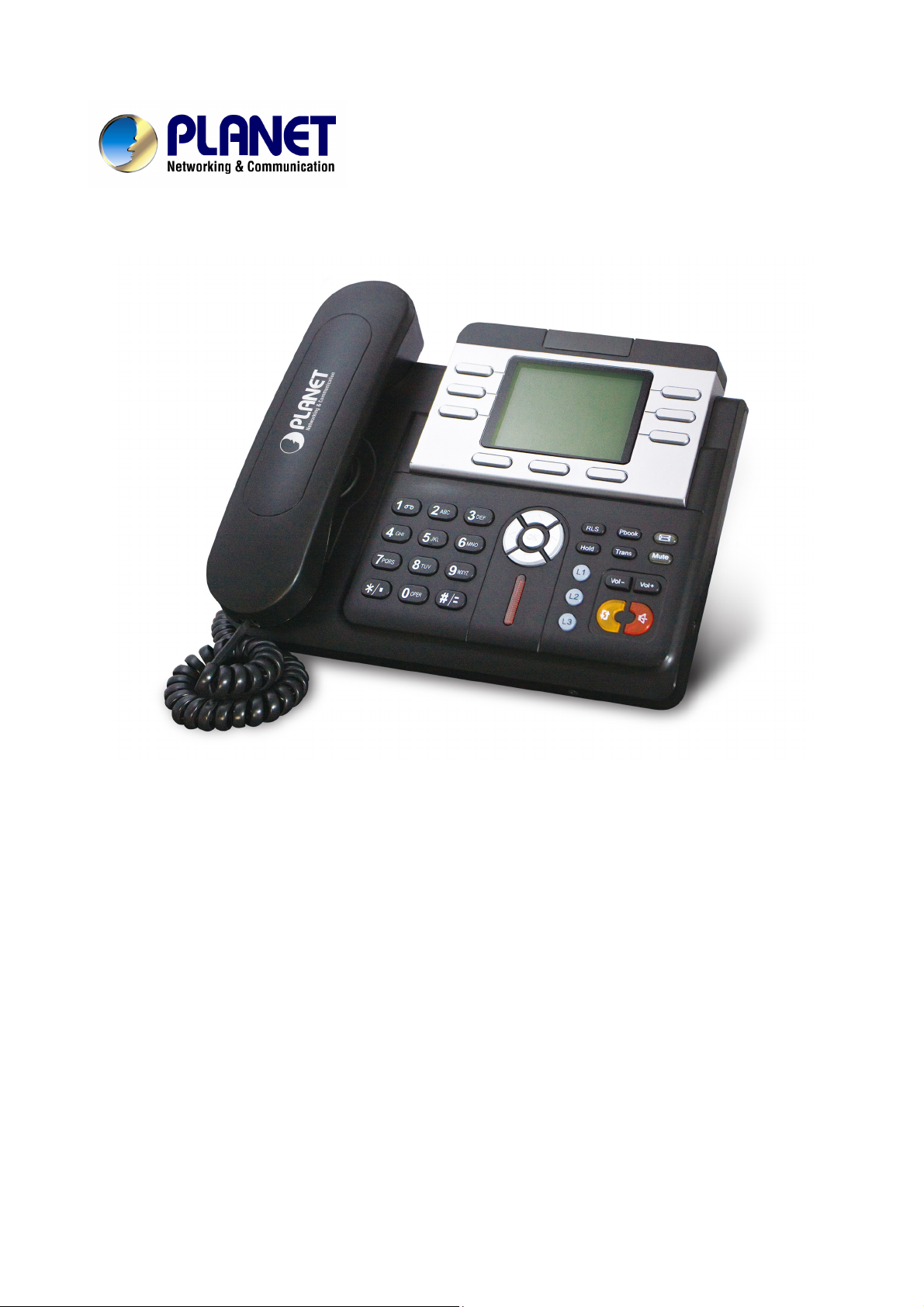
PLANET continues to bring innovation to the Voice over IP communications market with cutting edge products
and Internet telephony manufacturing experience. PLANET now introduces a new desktop PoE IP phone
family: the VIP-360PT.
The standard features of the VIP-360PT includes 3-line, dual 10/100 switched Ethernet ports and integrated
IEEE power over Ethernet (802.3af) circuitry for offering a choice of powering and cabling options to help
reduce cabling expenses and cord clutter.
To give most flexibility to users, the VIP-360PT platform contains a graphic LCD with Back light, 3 Line keys, 6
memory key, 3 soft-buttons, 9 fixed function keys and a navigation key. The PLANET VIP-360PT desktop
phone is engineered to make Easy-to-install communications, cost-effective to deploy, self-contained,
service-integrated, intelligent phone features offering and powerful voice processing power as possible.
The VIP-360PT can effortlessly deliver toll voice quality equivalent to the regular VoIP / IP PBX connections
utilizing cutting-edge 802.1p QoS (Quality of Service) capabilities to encompass, 802.1q VLAN tagging, echo
cancellation, comfort noise generation (CNG) and voice compensation technology. Meanwhile, the dual
Ethernet interfaces on the IP phone allow users to install in an existing network location without interfering
with connections of desktop PC networks.
The VIP-360PT has streamlined wired IP telephone that provides additional features such as built-in PPPoE /
DHCP clients, password-protected machine management, call hold, forwarding, mute, transfer, waiting,
pickup, caller ID, speed-dial, 3-way conference, last number redial, incoming message indicator, multiple call
appearances and user-intuitive web administration system.
Product Features
• IEEE 802.3af Power-over-Ethernet
• Full-Featured enterprise SIP Desktop Phone
• 802.1p (QoS) / 802.1q (VLAN)
• Full duplex speakerphone (mic and speaker)
• Pixel-based monochrome LCD with backlight
• Efficient installation deployment of IP PBX solution
• Reversible base stand / wall mount
Page 7
VoIP Features
• SIP 2.0 (RFC3261) compliant
• Supports up to 3 service domains
• Interoperability with leading PLANET IP PBX platforms
• Voice codec support: G.711(A-Law, u-Law), G.723.1, G.729 A/B, G.722,G.726
• In-band, out-of-band DTMF Relay (RFC 2833) and SIP INFO
• Three-way Conference / Caller ID / Speed Dial
• Call Hold / Mute / Forward / Transfer / Waiting
• Voice processing: VAD, CNG, AEC, Adaptive Jitter Buffer Management
Package Content
The contents of your product should contain the following items:
‧ Enterprise PoE IP Phone VIP-360PT unit
‧ Power Adapter
‧ Quick Installation Guide
‧ CD-ROM containing the user’s manual.
‧ Phone Stand
‧ RJ-45 cable
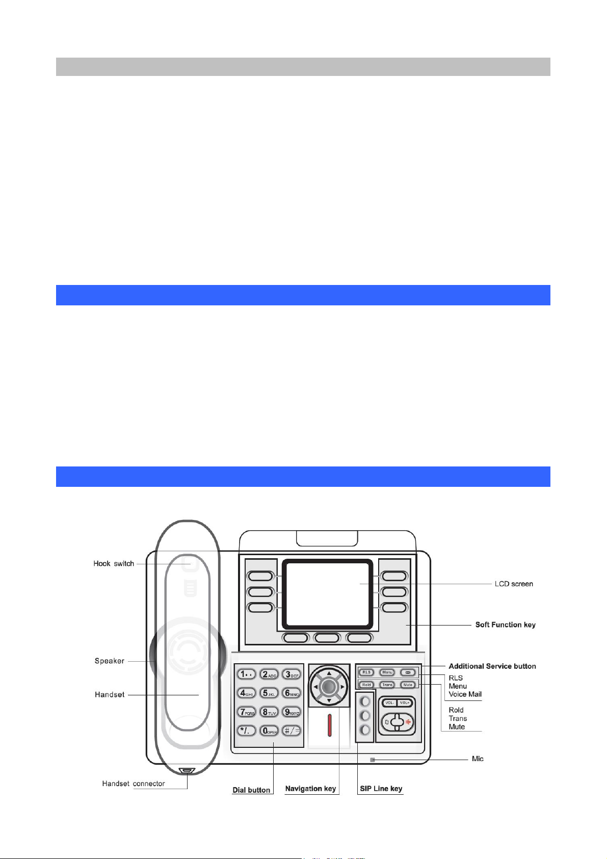
Physical Details
The following figure illustrates the front/rear panel of IP Phone.
Page 8
Keypad Description
1 LCD Display Menu and all status shall be displayed for users.
2 SIP Line Key
3 Soft-button To control SMS, SDial, Memo, etc function button.
4 Memory Key
5 PBook Access the phonebook
6 R/Send Redial the last dialed number, Access redial menu
7 Speaker Enable user to use the phone without handset
8 Vol+ Cycle through the phone menu Adjusting Volume louder
9 Vol- Cycle through the phone menu Adjusting Volume lower
10 Up Checking Missed Call
11 Down Checking IP info
12 Left Checking Incoming call
13 Right Checking line status
14 OK Enter into the phone’s menu
15 Hold Place the person on the other line on hold, answering call waiting.
16 Mute Key Press to mute sounds when at talk mode.
To make 3 line accounts dial call by pressing the Line1 ~ Line 3.
Users could store their commonly used number in these keys, and call
them as speed dial
17
Transfer
18 RLS Release a call without off-hook and quit
19 Envelop LED inside, if blinks remind user have new voicemail
Transfer the person you are conversing to another line.
Digit-character map table
Keypad Character Keypad Character
1 @
2 A B C a b c
3 D E F d e f
4 G H I g h i
5 J K L j k l
6 M N O m n o
7 P Q R S p q r s
8 T U V t u v
9 W X Y Z w x y z
*/.
0
#/=
Page 9
Physical Interfaces
1 WAN
2 LAN/PC
3 Power
4 Handset Jack
RJ-45 connector, for Internet access, connected directly to
Switch/Hub through straight CAT-5 cable.
The WAN interface also can be connected with 802.3af PoE
switch or converter for power supply
RJ-45 connector, to maintain the existing network structure,
connected directly to the PC through straight CAT-5 cable
5V DC Power input outlet
RJ-9 connector, for telephone handset
Page 10
Chapter 2
2
System Setup and Basic Operating
System Configurations for LCD / WEB
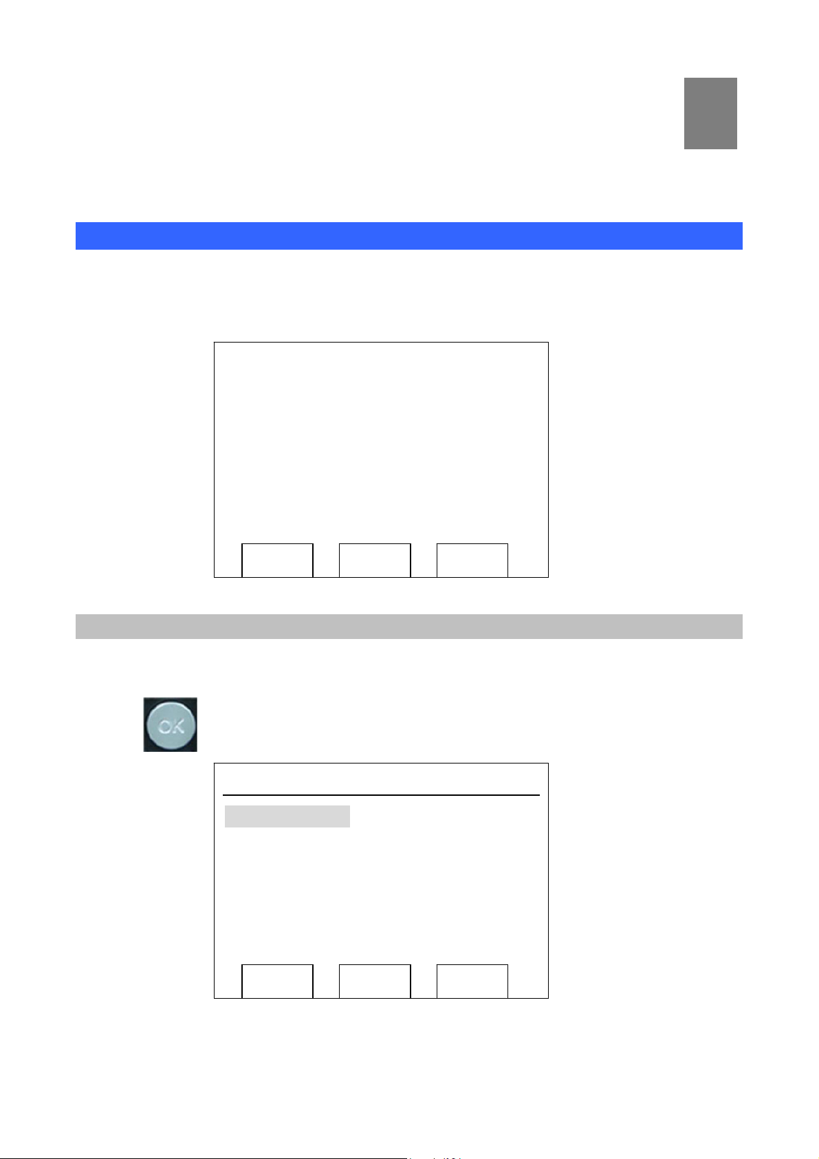
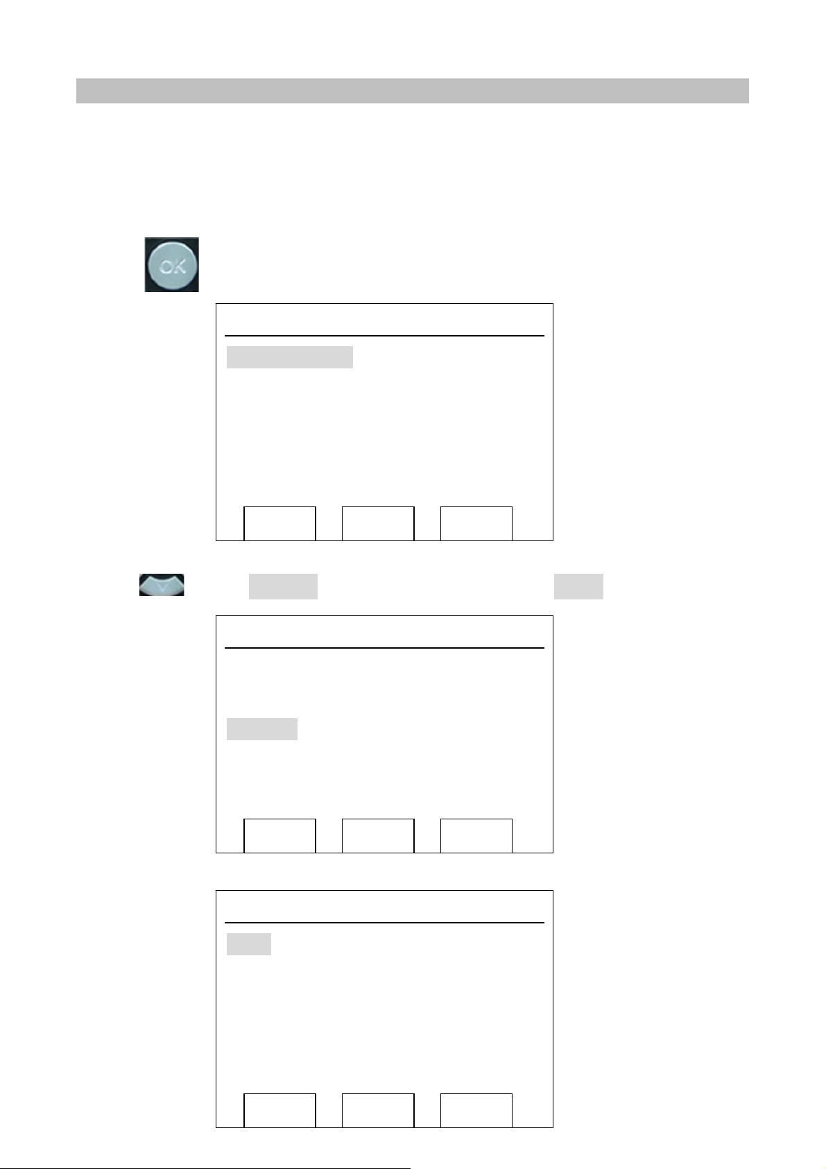
After Power on IP phone, you should see some text on the LCD screen of IP phone now. If not, please
redo step 5 to 6 until you can see some text on the LCD screen.
PLANET 13: 40: 45
2010/ 08/ 08
Sunday
VOIP PHONE
Memo SDial SMS
Network Setup (Static)
To setup static IP address, please follow instructions described in this chapter:
1. Press button on IP Phone
System Config
User Config
Network
Next Enter Quit
Menu
Page 11
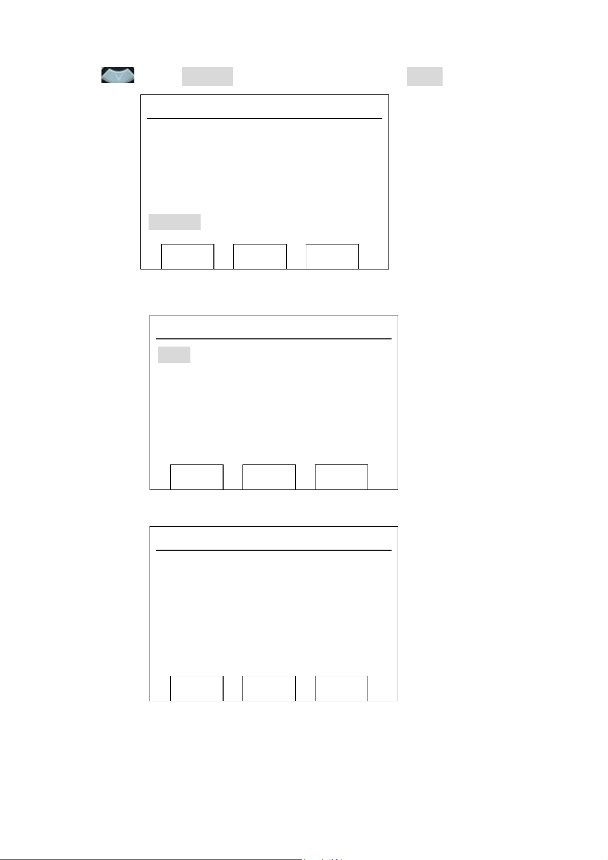
2. Press key until ‘Network’ is selected, then press "OK" or Soft2 ‘Enter’ key.
System Config LCD screen will display
“WAN”.
User Config
Network
LCD screen will display “WAN”.
Next Enter Quit
WAN
LAN
VLAN
Menu
Network
3. Press "OK" or Soft2 (Enter), then choose “Static”.
Next Enter Quit
Net Mode
<>Static
DHCP
PPPoE
Edit Save Quit
Page 12

4. Press Soft1Edit) and screen will show “IP”, then press Soft1 (Del) to delete. Input your IP address and
press Soft2 (Save) to save what you input. After “Saved” shown, the screen will jump to show the Net
mask information.
IP
192.168.0.36_
Del Save Quit
Netmask
255.255.255.0_
Static Set
Static Set
5.Press Soft1 (Del) to delete. Input your Net mask and press Soft2 (Save). After “Saved” shown, the
screen will jump to show the Gateway information.
Del Save Quit
Static Set
Gateway
192.168.0.1_
Del Save Quit
6. Press Soft1 (Del) to delete, Input your gateway and press Soft2 (Save). After “Saved” shown, the
screen will jump to show the DNS information.
Page 13

DNS
Static Set
7.
Press Soft1 (Del) to delete. Input your DNS server address and press Soft2 (Save). After “Saved”
shown, the screen will return to show IP information.
8.8.8.8_
Del Save Quit
Static Set
IP
192.168.0.36_
8. Press Soft3 (Quit) once, the screen shows” Net Mode”. the cursor stay at“<>Static”; with Soft2(Save)
pressed,the screen shows “Saved” and then shows the current net mode.
9.
Press or Soft3 (Quit) thrice,
to change to Static mode
Del Save Quit
Net Mode
<>Static
DHCP
PPPoE
Edit Save Quit
return to main interface and at this time the phone is trying
. Press button, the screen shows “Static” .the screen shows the IP address
and gateway which were set just now, if the phone could display the right time, it shows that Static IP
mode takes effect.
Page 14
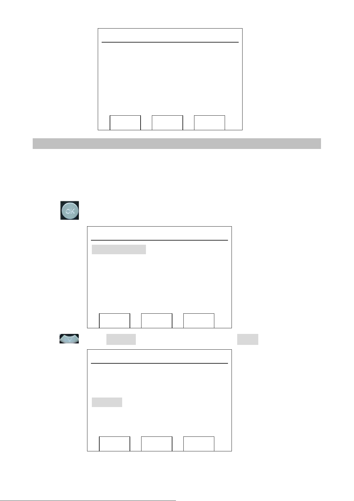
Network
Mode: Static
IP: 192.168.0.36
GW:192.168.0.1
Quit
Network Setup (PPPoE)
By using PPPoE, you don’t have to setup IP address by yourself. Instead, an IP address will be issued to
your IP phone by internet service provider automatically, which is more convenient.
To complete your network setup using PPPoE, please follow instructions described in this chapter:
1. Get PPPoE account and password first.
2. Press
button on IP Phone
Menu
System Config
User Config
3. Press key until ‘Network’ is selected, then press "OK" or Soft2 ‘Enter’ key.
Network
Next Enter Quit
Menu
System Config
User Config
Network
Next Enter Quit
Page 15

LCD screen will display “WAN”.
WAN
LAN
Network
VLAN
4. Press "OK" or Soft2 (Enter), then choose “PPPoE”.
Next Enter Quit
Net Mode
Static
DHCP
<> PPPoE
5. Press Soft1 (Edit), the screen will display “Account”. The screen will show the current account
information. Press Soft1 (Del) to delete it, then input your PPPoE account and press Soft2 (Save). With
“saved” displayed, screen will jump to password settings
Account
User123
Save Edit Quit
PPPoE Set
Save Del Quit
Page 16
PPPoE Set
6. Press Soft2 (Del) again, then input your PPPoE password and press Soft2 (OK), With “Saved”
displayed, screen will display the current password: ******,press soft2 (OK) to save the Account and
password. The screen will show “Saved” and then jump to show the current net mode.
Password
***********
Save Del Quit
Net Mode
Static
DHCP
7. Press
PPPoE mode. Press
the phone is trying to access to the PPPoE Server; if it shows an IP address, then the phone has already
get IP with PPPoE
<> PPPoE
Save Edit Quit
or Soft3 (Quit) thrice return to standby, at this time the phone is trying to change to
for checking the status. If the screen shows “Negotiating…” it shows that
Network
Mode: PPPoE
Negotiating…
Quit
Page 17
Network Setup (DHCP)
By using DHCP, you don’t have to setup IP address by yourself. Instead, an IP address will be issued to
your IP phone by DHCP server on your local network automatically, which is more convenient.
To complete your network setup using DHCP, please follow instructions described in this chapter:
1. Press button on IP Phone
System Config
User Config
Network
Next Enter Quit
Menu
2. Press key until ‘Network’ is selected, then press "OK" or Soft2 ‘Enter’ key.
Menu
LCD screen will display “WAN”.
System Config
User Config
Network
Enter Next Quit
Network
WAN
LAN
VLAN
Enter Next Quit
Page 18
3. Press "OK" or Soft2 (Enter), then choose “DHCP”.
Net Mode
4. Press Soft2 (Save), with “saved” shown, screen will jump to show the current net mode.
Static
<> DHCP
PPPoE
Save
Net Mode
Static
<> DHCP
Quit
PPPoE
5.
Press or Soft3 (Quit) thrice back
change to DHCP mode
address and gateway which were set just now, it shows that DHCP mode takes effect.
Save Quit
to main interface and at this time phone is trying to
. Press until the phone shows “DHCP”,If the screen shows the IP
Network
Mode: DHCP
IP: 192.168.0.109
GW:192.168.0.1
Quit
Page 19

Network set up from web
1. Use the web browser on your computer to connect to the IP address of IP Phone. For example, The
IP Phone’s default IP address is 192.168.0.1, please type ‘http://192.168.0.1’ in the browser’s
address bar. A login window will appear, please enter the username and password.
If you do not know the IP address, you can look it up on the phone’s display by pressing
button.
NOTE: default username is ‘admin’, and password is ‘123.
※
After you configure the IP phone, you need click save button in config under Maintenance in the left
catalog to save your configuration. Otherwise the phone will lose your modification after power off
and on.
2. After you have logged in, you’ll see the brief information of current network setting. Please click
‘Network’ link on the left.
Page 20
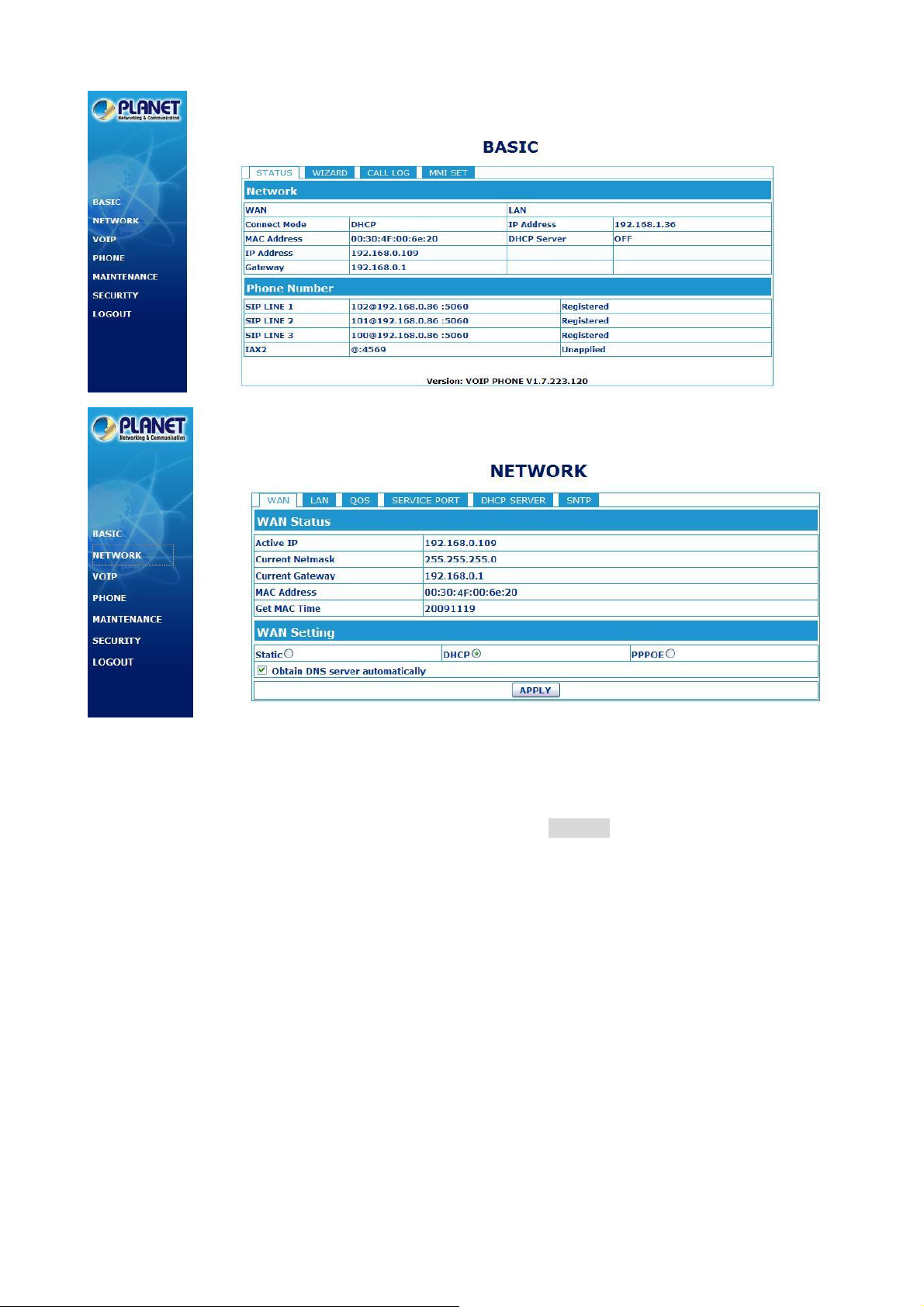
3. here, you can choose connection mode (static IP, PPPoE, or DHCP), enter IP address for static IP
mode, and enter PPPoE username and password directly on web page. If you want to enable VLAN
function of PC and phone Ethernet port of this IP Phone, you can also set it up here.
After you have entered the setting you need, remember to click ‘APPLY’ button located at the bottom of
the web page.
Page 21

WAN Config
Active IP The current IP address of the phone.
Current Netmask The current Netmask address.
MAC Address The current MAC address of the phone.
Current Gateway The current Gateway IP address.
Get MAC Time Shows the time of getting MAC address
Please select the proper network mode according to the network condition. VIP-360PT provides three
different network settings:
Static: If your ISP server pr
Static Mode setting. If you don’t know about parameters of Static Mode setting, please ask your ISP fo
them.
DHCP:
this information artificially.
PPPoE: In this mode, your
In this mode, you will get the information from the DHCP server automatically; need not to input
ovides you the static IP address, please select this mode, and then finish
must input your ADSL account and password.
r
Page 22

Get DNS server automatically
Select it to use DHCP mode to get DNS address, if you don’t select it, you will use static DNS server.
The default is selecting it.
If you use static mode, you need set it.
IP Address Input the IP address distributed to you.
Netmask Input the Netmask distributed to you.
Gateway Input the Gateway address distributed to you.
DNS Domain Set DNS domain postfix. When the domain which you input can not be
parsed, phone will automatically add this domain to the end of the
domain which you input before and parse it again.
Primary DNS Input your primary DNS server address.
Alter DNS Input your standby DNS server address.
If you uses PPPoE mode, you need to make the above setting.
PPPoE Server It will be provided by ISP.
Username Input your ADSL account.
Password Input your ADSL password.
Notice:
1)Click “Apply" button after finished your setting, IP Phone will save the setting automatically and
new setting will take effect.
2)If you modify the IP address, the web will not response by the old IP address. Your need input new IP
address in the address column to logon in the phone.
3)If networks ID which is DHCP server distributed is same as network ID which is used by LAN of
system, system will use the DHCP IP to set WAN, and modify LAN's networks ID(for example, system
will change LAN IP from 192.168.10.1 to 192.168.11.1) when system uses DHCP client to get IP in
startup; If system uses DHCP client to get IP in running status and network ID is also same as LAN’s,
system will refuse to accept the IP to configure WAN. So WAN’s active IP will be 0.0.0.0
Page 23

LAN Config
LAN Config
LAN IP Specify LAN static IP.
Netmask Specify LAN Netmask.
DHCP Service Select the DHCP server of LAN port or not. After you modify the LAN IP
address, phone will amend and adjust the DHCP Lease Table and save the
result amended automatically according to the IP address and Netmask. You
need restart the phone and the DHCP server setting will take effect.
NAT Select NAT or not.
Bridge Mode Select Bridge Mode or not: If you select Bridge Mode, the phone will no longer
set IP address for LAN physical port,LAN and WAN will join in the same
network. Click “Apply”, the phone will reboot.
Notice: If you choose the bridge mode, the LAN configuration will be disabled.
Page 24

Qos Config
The VOIP phone support 802.1Q/P protocol and DiffServ configuration. VLAN functionality can use
different VLAN IDs by setting signal/voice VLAN and data VLAN. The VLAN application of this phone is
very flexible.
In chart 1, there is a layer 2 switches without setting VLAN. Any broadcast frame will be transmitted to
the other ports except the send port. For example, a broadcast information is sent out from port 1 then
transmitted to port 2,3and 4.
In chart 2, red and blue indicate two different VLANs in the switch, and port 1 and port 2 belong to red
VLAN, port 3 and port 4 belong to blue VLAN. If a broadcast frame is sent out from port 1, switch will
transmit it to port 2, the other port in the red VLAN and not transmit it to port3 and port 4 in blue VLAN.
By this means, VLAN divide the broadcast domain via restricting the range of broadcast frame
transmission
Note: chart 2 use red and blue to identify the different VLAN, but in practice, VLAN uses different VLAN
IDs to identify.
Page 25

QoS Configuration
Field name explanation
VLAN Enable Before select it to enable VLAN, you need enable Bridge mode in LAN config.
VLAN ID Check Enable Enable VLAN ID check by selecting it. After enable VLAN ID check, if VLAN
ID of a data package is not the same with the phones or a data package do
not have VLAN ID, the data package will be discarded.
Voice/Data VLAN
differentiated
DiffServ Enable Select it or not to Enable or disable DiffServ.
DiffServ Value Set DiffServ value, the common value is 0x00.
Voice 802.1P Priority Specify 802.1P Priority of voice/signal data package.
Data 802.1P Priority Set 802.1p of data VLAN. Non-VoIP data (such as http, telnet, ping etc) will
Voice VLAN ID Set VLAN ID of voice/signal data package.
Data VLAN ID Set 802.1q of data VLAN ID. Non-VoIP data (such as http, telnet, ping etc)
Notice:
1)Startup VLAN, if set Voice/Data VLAN differentiated as Undifferentiated, all packets will use the Voice
VLAN ID as the tag.
After enable VLAN, system will set packets with different type of VLAN ID.
Undifferentiated means after using VLAN, both VoIP packets and other data
packets will use the voice VLAN ID; tag differentiated means after using
VLAN, VoIP(signal and voice) packets will add voice VLAN ID, and other data
packets will add data VLAN ID; data untagged means after using VLAN, only
VoIP packets will add voice VLAN ID. Other data packets will not use VLAN.
use this value to set VLAN package.
will use this value to set VLAN package.
2) Startup VLAN, if set Voice/Data VLAN differentiated as tag differentiated and disables the DiffServ,
then system will not distinguish the voice and data, all packets will use the Voice VLAN ID as the tag.
3) Startup VLAN, if set Voice/Data VLAN differentiated as tag differentiated and enables the DiffServ,
then system will distinguish the voice and data and add the VLAN ID each other.
4) Startup VLAN, if set Voice/Data VLAN differentiated as data untagged, then the packet of the
signal/voice will use the Voice VLAN ID as the tag, but the data packets will not take the VLAN tag.
Page 26

5) If Disable the VLAN, regardless to set the Voice/Data VLAN differentiated or not, all packets will not
take the VLAN tag; If enable the DiffServ, all packets will only take the DiffServ value.
6) One must to notice, enable the VLAN ID Check Enable that is default, If enable it, the phone will
match the VLAN ID strictly. When others' VLAN ID not matches with us, the packets will discard.
Contrarily, the phone will accept the packets with the distinct VLAN ID.
7) You must gain the IP with the Static mode when you set VLAN, otherwise can't gain the IP in the
VLAN and also can not dial with point to point.
Service Port
You can set the port of telnet/HTTP/RTP by this page.
SERVICE PORT
Field name explanation
HTTP Port set web browse port, the default is 80 port,if you want to enhance system safety,
you'd better change it into non-80 standard port;
Example: The IP address is 192.168.1.70. and the port value is 8090, the
accessing address is http://192.168.1.70:8090
Telnet Port Set Telnet Port, the default is 23. You can change the value into others.
Example:
The IP address is 192.168.1.70. the telnet port value is 8023, the accessing
address is telnet 192.168.1.70 8023
RTP Initial Port Set the RTP Initial Port. It is dynamic allocation.
RTP Port Quantity Set the maximum quantity of RTP Port, the default is 200.
Notice:
1)You need save the configuration and reboot the phone after set this page.
2)If you modify the port of Telnet and HTTP, you would better set the value more than 1024 because the
port value less than 1024 is system port reserved.
3)if you set 0 for the HTTP port, it will disable HTTP service.
Page 27

DHCP SERVER
DHCP SERVER
Field name explanation
DHCP Leased
Table
IP-MAC mapping table. If the LAN port of the phone connects to a device, this
table will show the IP and MAC address of this device.
Shows the DHCP Lease Table, the unit of Lease time is Minute.
Lease Table Name Specify the name of the lease table
Start IP Set the start IP address of the lease table
End IP Set the end IP address of the lease table, the network device connected to LAN
port will get IP address between Start IP and End IP by DHCP.
Netmask Set the Netmask of the lease table
Gateway Set the Gateway of the lease table
Lease Time Set the Lease Time of the lease table
Page 28

DNS
Select name of lease table, click the Delete button will delete the selected lease table from DHCP lease
table.
DNS Relay Select DNS Relay, the default is enabled. Click the Apply button to become effective.
Notice:
1)The size of lease table can not be larger than the quantity of C network IP address. We recommend
you to use the default lease table and not modify it.
2)If you modifies the DHCP lease table, you need save the configuration and reboot.
Set the default DNS server IP of the lease table; Click the Add button to submit
and add this lease table
Page 29

SNTP
Setting time zone and SNTP (Simple Network Time Protocol) server according to your location, you can
also manually adjust date and time in this web page.
SNTP
Field name explanation
Server Set SNTP Server IP address.
Time Zone Select the Time zone according to your location.
Time Out Set the time out, the default is 60 seconds.
12 Hours
Systems
SNTP Select the SNTP, and click Apply to make the SNTP Times effective.
Enable Daylight Enable daylight saving time
Switch the time mechanism between 12 hours and 24 hours.
Default is 24 hours mode
Page 30

Time
shift(minutes)
Month Setup stat and end month
Week Setup start and end week
Day Setup start and end day
Hour Setup start and end hours
Minute Setup start and end minutes
Notice: You need specify the above all items.
Setup the variety length
Page 31

Chapter 3
3
SIP Service Configurations
Configuring SIP setting for IP Phone
SIP is a request-response protocol, dealing with requests from clients and responses from servers.
Participants are identified by SIP URLs. Requests can be sent through any transport protocol. SIP determines
the end system to be used for the session, the communication media and media parameters, and the called
party's desire to engage in the communication. Once these are assured, SIP establishes call parameters at
either end of the communication, and handles call transfer and termination.
SIP Config
Set your SIP server in the following interface
Page 32

Page 33

SIP Config
Field name explanation
Register Status Shows if the phone has been registered the SIP server or not; or so, show
Unapplied;
Server Name Set the server name.
Server Address Input your SIP server address.
Server Port Set your SIP server port.
Account Name Input your SIP register account name.
Password Input your SIP register password.
Phone Number Input the phone number assigned by your VoIP service provider. Phone will
not register if there is no phone number configured.
Display Name Set the display name.
Proxy Server Address Set proxy server IP address(Usually, Register SIP Server configuration is
the same as Proxy SIP Server. But if your VoIP service provider give
different configurations between Register SIP Server and Proxy SIP
Server, you need make different settings.)
Proxy Server Port Set your Proxy SIP server port.
Proxy Username Input your Proxy SIP server account.
Proxy Password Input your Proxy SIP server password.
Domain Realm Set the sip domain if needed, otherwise this VoIP phone will use the
Register server address as sip domain automatically. (Usually it is same
with registered server and proxy server IP address).
Enable Register Start to register or not by selecting it or not.
Register Expire Time Set expire time of SIP server register, default is 60 seconds. If the register
time of the server requested is longer or shorter than the expire time set,
the phone will change automatically the time into the time recommended by
the server, and register again.
NAT Keep Alive Interval Set examining interval of the server, default is 60 seconds
User Agent Set the user agent if have, the default is VoIP Phone 1.0
Signal Key Set the key for signal encryption
Media Key Set the key for RTP encryption
Local port Set sip port of each line
Ring type Set ring type of each line
Hot line Number Set hot line number of each line
Conference Number Configure conference number in server conference.
Page 34

Transfer Expire Time For the phone supports the transfer of certain special features server, set
interval time between sending “bye” and hanging up after the phone
transfers a call.
Enable subscribe Enable the option, the phone will receive the notify from the server.
Enable Keep
Authentication
Enable/Disable Keep Authentication System will take the last
authentication field which is passed the authentication by server to the
request packet. It will decrease the server’s repeat authorization work, if it
is enable.
NAT Keep Alive Enable/Disable keeps NAT of SIP alive.
If some server refuse to register with too short interval time, and
has no packets sending to device in private network to keep NAT alive,
user could set this function ON. It need set the keep alive interval time less
than the NAT server’s.
Enable Via rport Enable/Disable system to support RFC3581. Via rport is special way to
realize SIP NAT.
Enable PRACK Enable or disable SIP PRACK function, suggest use the default config.
Long Contact
Set more parameters in contact field; connection with SEM server
Enable URI Convert Convert # to %23 when send the URI.
Dial Without Register Set call out by proxy without registration;
Ban Anonymous Call Set to ban Anonymous Call;
Forward Type Select call forward mode, the default is Off
Off:Close down calling forward
Busy:If the phone is busy, incoming calls will be forwarded to the
appointed phone.
No answer: If there is no answer, incoming calls will be forwarded to the
appointed phone.
Always:Incoming calls will be forwarded to the appoint phone directly.
The phone will Prompt the incoming while doing forward.
Forward Phone Number Appoint your forward phone number.
Server Type Select the special type of server which is encrypted, or has some unique
requirements or call flows.
DTMF Mode
Select DTMF sending mode, there are three modes:
DTMF_RELAY
DTMF_RFC2833
DTMF_SIP_INFO
Different VoIP Service providers may provide different modes.
RFC Protocol Edition Select SIP protocol version to adapt for the SIP server which uses the
same version as you select. For example, if the server is CISCO5300, you
need to change to RFC2543; else phone may not cancel call normally.
System uses RFC3261 as default.
Page 35

Transport Protocol Set transport protocols, TCP or UDP;
RFC Privacy Edition Set Anonymous call out safely; Support RFC3323and RFC3325;
Subscribe Expire Time Overtime of resending subscribe packet. Suggest using the default config.
Enable Conference
Set to use sever conference.
number
MWI Number Input the number of the server's voice-mail box
Click to Talk Set click to Talk (need practical software support).
Signal Encode Enable/Disable Signal Encrypt.
RTP Encode Enable/Disable RTP Encrypt.
Enable Session Timer Set Enable/Disable Session Timer, whether support RFC4028. It will
refresh the SIP sessions.
Answer With Single
Codec
Answer With Single
Codec
Enable/Disable the function when call is incoming, phone replies SIP
message with just one codec which phone supports.
Enable/Disable the function when call is incoming, phone replies SIP
message with just one codec which phone supports.
Auto TCP Set to use automatically TCP protocol to guarantee usability of transport as
message is above 1300 byte
Enable Strict Proxy
Support the special SIP server-when phone receives the packets sent from
server, phone will use the source IP address, not the address in via field.
Enable GRUU Set to support GRUU
Enable Display name
Quote
Enable GRUU Set to support GRUU
Set to make quotation mark to display name as the phone sends out signal,
in order to be compatible with server.
Page 36

IAX2 Config
IAX2 Config
Field name explanation
Register Status Shows if the phone has been registered the IAX2 server or not.
IAX2 Server Addr Input your IAX2 server address.
IAX2 Server Port Set your IAX2 server port, the default is 4569.
Account Name Input your IAX2 register account name.
Account Password Input your IAX2 register password.
Phone Number Input your assigned phone number (usually it is same you’re your IAX2
account name).
Local Port Set your local sport,the default is 4569.
Voice Mail Number Specify the voice mail’s number.
Voice Mail Text Specify the voice mail’s name.
Echo Test Number Set echo test number. If IAX2 server supports echo test, and echo test
number is non- numeric, system could set an echo test number to replace
the echo test text. So user can dial the numeric number to test echo voice
test. This function is provided with server to make endpoint to test whether
endpoint could talk through server normally.
Page 37

Echo Test Text Specify echo test text’s name.
Refresh Time Set expire time of IAX2 server register, you can set it between 60 and 3600
seconds.
Enable Register Start to register the IAX2 server or not by selecting it or not.
Enable G.729 Enable or disable code G.729 by selecting it or not
Stun Config
In this web page, you can config SIP STUN.
STUN:
By STUN server, the phone in private network could know the type of NAT and the NAT mapping IP and
port of SIP. The phone might register itself to SIP server with global IP and port to realize the device both
calling and being called in private network.
Page 38

STUN
Field name explanation
STUN NAT Transverse Shows STUN NAT Transverse estimation, true means STUN can penetrate
NAT, while False means not.
STUN Server Addr Set your SIP STUN Server IP address
STUN Server Port Set your SIP STUN Server Port
STUN Effect Time Set STUN Effective Time. If NAT server finds that a NAT mapping is idle after
time out, it will release the mapping and the system need send a STUN
packet to keep the mapping effective and alive.
Local SIP Port Set the SIP port.
Choose line to set info about SIP, There are 3 lines to choose. You can switch by 【Load】
button.
Use Stun
Enable/Disable SIP STUN.
Notice: SIP STUN is used to realize SIP penetration to NAT. If your phone configures STUN Server IP
and Port (default is 3478), and enable SIP Stun, you can use the ordinary SIP Server to realize
penetration to NAT.
DIAL PEER setting
This functionality offers you more flexible dial rule, you can refer to the following content to know how to
use this dial rule. When you want to dial an IP address, the entry of IP addresses is very cumbersome,
but by this functionality, you can set number 156 to replace 192.168.1.119 here.
When you want to dial a long distance call to Beijing, you need dial an area code 010 before local phone
number, but you can also dial number 1 instead of 010 after we make a setting according to this dial rule.
For example, you want to dial 01062213123, but you need dial only 162213123 to realize your long
distance call after you make this setting.
To save the memory and avoid abundant input of user, add the follow functions:
Page 39

1、x Match any single digit that is dialed.
If user makes the above configuration, after user dials 11 digit numbers started with 13, the
phone will send out 0 plus the dialed numbers automatically.
2、
[] Specifies a range that will match digit. It may be a range, a list of ranges separated by commas, or
a list of digits.
If user makes the above configuration, after user dials 11 digit numbers started with from 135 to
139, the phone will send out 0 plus the dialed numbers automatically.
Use this phone you can realize dialing out via different lines without switch in web interface.
DIAL PEER
Field name explanation
Phone number There are two types of matching conditions: one is full matching, the
other is prefix matching. In the Full matching, you need input your
desired phone number in this blank, and then you need dial the phone
number to realize calling to what the phone number is mapped. In the
prefix matching, you need input your desired prefix number and T;
then dial the prefix and a phone number to realize calling to what your
prefix number is mapped. The prefix number supports at most 30
digits
Page 40

Destination Set Destination address. This is optional config item. If you want to set
peer to peer call, please input destination IP address or domain name.
If you want to use this dial rule on SIP2 line, you need input
255.255.255.255 or 0.0.0.2 in it.SIP3 into 0.0.0.3
Port Set the Signal port, the default is 5060 for SIP.
Alias Set alias. This is optional config item. If you don’t set Alias, it will show
no alias.
Note: There are four types of aliases.
1) add: xxx, it means that you need dial xxx in front of phone number, which will reduce dialing number
length.
2) all: xxx, it means that xxx will replace some phone number.
3) del: It means that phone will delete the number with length appointed.
4) Rep: It means that phone will replace the number with length and number appointed.
You can refer to the following examples of different alias application to know more how to use different
aliases and this dial rule.
Call Mode Select different signal protocol, SIP or IAX2
Suffix Set suffix, this is optional config item. It will show no suffix if you don’t set it.
Delete Length Set delete length. This is optional config item. For example: if the delete length is
3, the phone will delete the first 3 digits then send out the rest digits. You can refer
to examples of different alias application to know how to set delete length.
Examples of different alias application
Set by web explanation example
You need set phone number,
Destination, Alias and Delete
Length.
Phone number is XXXT;
Destination is 255.255.255.255
(0.0.0.2) and Alias is del.
This means any phone No. that
If you dial “93333”,
the SIP2 server
will receive “3333”
starts with your set phone number
will be sent via SIP2 line after the
first several digits of your dialed
phone number are deleted
according to delete length.
Page 41

This setting will realize speed dial
When you dial “2”,
function, after you dialing the
numeric key “2”, the number after
all will be sent out.
The phone will automatically send
out alias number adding your
dialed number, if your dialed
number starts with your set phone
number.
You need set Phone Number,
Alias and Delete Length. Phone
the SIP1 server
will receive
33334444
When you dial
“8309“, the SIP1
server will receive
“07558309”
When you dial
“0106228”, the
number is XXXT and Alias is
rep:xxx
If your dialed phone number starts
with your set phone number, the
first digits same as your set phone
number will be replaced by the
alias number specified and New
phone number will be send out.
If your dialed phone number starts
with your set phone number. The
phone will send out your dialed
phone number adding suffix
number.
SIP1 server will
receive
“0086106228”
When you dial
“147”, the SIP1
server will receive
“1470011”
Page 42

Phone
DSP Config
In this page, you can configure voice codec, input/output volume and so on.
DSP Configuration
Field name explanation
First Codec The fist preferential DSP codec: G.711A/u, G.722, G.723, G.729
Second Codec The second preferential DSP codec: G.711A/u, G.722, G.723, G.729
Third Codec The third preferential DSP codec: G.711A/u, G.722, G.723, G.729
Forth Codec The forth preferential DSP codec: G.711A/u, G.722, G.723, G.729
Fifth Codec The fifth preferential DSP codec: G.711A/u, G.722, G.723, G.729
Input Volume Specify Input (MIC) Volume grade.;
Hands-free Volume Specify Hands-free Volume grade
G729 Payload Length Set G729 Payload Length
Handdown Time Specify the least reflection time of Handdown, the default is 200ms.
Ring Type Select Ring Type
Output Volume Specify Output (receiver) Volume grade.
Ring Volume Specify Ring Volume grade
G722 Timestamps 160/20ms or 320/20ms is available
G723 Bit Rate 5.3kb/s or 6.3kb/s is available
Default Ring Type Set up the ring by default
Signal Standard Select Signal Standard.
VAD Select it or not to enable or disable VAD. If enable VAD, G729 Payload length
could not be set over 20ms.
Page 43

Call Service
In this web page, you can configure Hotline, Call Transfer, Call Waiting, 3 Ways Call, Black List, white list
Limit List and so on.
Call Service
Field name explanation
Hotline Specify Hotline number. If you set the number, you can not dial any other
numbers.
No Answer Time Specify No Answer Time
P2P IP Prefix Set Prefix in peer to peer IP call. For example: what you want to dial is
192.168.1.119, If you define P2P IP Prefix as 192.168.1., you dial only
#119 to reach 192.168.1.119. Default is “.”. If there is no “.” Set, it means to
disable dialing IP.
Remote Record No Set Remote Record number. Via dialing this number, you can hear all
voice records in your VoIP server.
Do Not Disturb Select NO Disturb, the phone will reject any incoming call, the callers will
be reminded by busy, but any outgoing call from the phone will work well.
Ban Outgoing If you select Ban Outgoing to enable it, and you can not dial out any
number.
Page 44

Enable Call Transfer Enable Call Transfer by selecting it.
Enable Call Waiting Enable Call Waiting by selecting it.
Enable Three Way Call Enable Three Way Call
Accept Any Call If select it, the phone will accept the call even if the called number is not
belong to the phone.
Auto Answer If select it, the phone will auto answer when there is an incoming call.
Use Record Server Select it or not to Enable or disable Use Record Server.
Auto handdown The phone will hang up and return to standby automatically at hands-free
mode
Black List Set Add/Delete Black list. If user does not want to answer some phone
calls, add these phone numbers to the Black List, and these calls will be
rejected.
“x” and “.” are wildcard.
The (x) means matching any single digit. for example, 4xxx expresses any
number with prefix 4 which length is 4 will be forbidden to dialed out
DOT (.) means matching any arbitrary number digit. For example, “6.”
expresses any number with prefix 6 will be forbidden to dialed out.
If user wants to allow a number or a series of number incoming, he may
add the number(s) to the list as the white list rule. the configuration rule is
-number, for example, -123456, or -1234xx
Means any incoming number is forbidden except for 4119
Note: End with DOT (.) when set up the white list
Limit List Set Add/Delete Limit List. Please input the prefix of those phone numbers
which you forbid the phone to dial out. For example, if you want to forbid
those phones of 001 as prefix to be dialed out, you need input 001 in the
blank of limit list, and then you can not dial out any phone number whose
prefix is 001.
“x” and “.” are wildcard.
The (x) means matching any single digit. for example, 4xxx expresses any
number with prefix 4 which length is 4 will be forbidden to dialed out
The DOT (.) means matching any arbitrary number digit. for example, 6.
Notice: Black List and Limit List can record at most10 items respectively.
expresses
any number with prefix 6 will be forbidden to dialed out.
Digital Map Configuration
This system supports 4 dial modes:
Page 45

1). End with “#”: dial your desired number, and then press #.
2). Fixed Length: the phone will intersect the number according to your specified length.
3). Time Out: After you stop dialing and waiting time out, system will send the number collected.
4). User defined: you can customize digital map rules to make dialing more flexible. It is realized by
defining the prefix of phone number and number length of dialing.
In order to keep some users' secondary dialing manner when dialing the external line with PBX, phone
can be added a special rule to realize it. So user can dial a number as external line prefix and get the
secondary dial tone to keep dial the external number. After finishing dialing, phone will send the prefix
and external number totally to the server.
For example, there is a rule 9, xxxxxxxx in the digital map table. After dialing 9, phone will send the
secondary dial tone, user may keep going dialing. After finished, phone will call the number which starts
with 9; actually the number sent out is 9-digit with 9.
Digital Map Configuration
Field name explanation
End with "#" Set Enable/Disable the phone ended with “#” dial.
Fixed Length Specify the Fixed Length of phone ending with.
Time out Set the timeout of the last dial digit. The call will be sent after timeout.
Below is user-defined digital map rule:
[] Specifies a range that will match digit. May be a range, a list of ranges separated by commas, or a list
of digits.
The “x” Match any single digit that is dialed.
The “.” Match any arbitrary number of digits including none.
“Tn” Indicates an additional time out period before digits are sent of n seconds in length. “n” is mandatory
and can have a value of 0 to 9 seconds. “Tn” must be the last 2 characters of a dial plan. If “Tn” is not
specified it is assumed to be T0 by default on all dial plans.
Page 46

Cause extensions 1000-8999 to be dialed immediately
Cause 8 digit numbers started with 9 to be dialed immediately
Cause 911 to be dialed immediately after it is entered.
Cause 99 to be dialed after 4 seconds.
Cause any number started with 9911 to be dialed 4 seconds after dialing ceases.
Notice: End with “#”, Fixed Length, Time out and Digital Map Table can be used simultaneously, System
will stop dialing and send number according to your set rules.
Phone Book
You can input the name, phone number and select ring type for each name here.
Page 47

Field name explanation
Shows the detail of current phonebook.
Phone Book
Name
Number Shows the phone number
Ring Type Shows the ring type of the incoming call.
Click “Modify” to change the selected information and click the “Delete” to delete the selected record.
Notice: the maximum capability of the phonebook is 500 items
Shows the name corresponding to the phone number
Function Key
Function Key
Field name explanation
Contrast Set contrast of screen
Luminance Set luminance of screen
MWI Number To listening record in server, we defined the function key F10, After you
set it, you can pick up or hands-free, and then press
record in server.
to listen
Page 48

Line: select SIP1, SIP2, SIP3, Dial peer, or IAX2 in function key type. After you set it, you pick up
handset or hands-free, press this function key, and then you can use the corresponding IP line.
Memory Key: you can set a number for each memory key. After set it, you can dial the number you set
by pressing this memory key.
Key event: function mode
Remark:
You can set speed dial function by Memory Key mode.
For example, you need set speed dial 8000 via sip 1.
Select memory key in F4’s function key type, then fill 8000@1/f in the corresponding right table.
You can set shortcut key of pbook, redial, DND, MWI, call forward, or callers by Key Event mode in
function key type.
Select key event in function key type, then fill F_PBOOK, F_REDIAL, F_DND, F_MWI, F_CFWD, or
F_CALLERS in the corresponding right table.
For example:
Page 49

Maintenance
Auto Provision
Auto Provision
Field name explanation
Current Config Version Show the current config file’s version.
Server Address Set FTP/TFTP/HTTP server IP address for auto update. The address
can be IP address or Domain name with subdirectory.
Username Set FTP server Username. System will use anonymous if username
keep blank.
Password Set FTP server Password.
Config File Name Set configuration file’s name which need to update. System will use
MAC as config file name if config file name keep blank. For example,
000102030405.。
Config Encrypt Key Input the Encrypt Key, if the configuration file is encrypted.
Protocol Type Select the Protocol type FTP、TFTP or HTTP.
Update Interval Time Set update interval time, unit is hour.
Update Mode Different update modes:
1. Disable: means no update
2. Update after reboot: means update after reboot.
3. Update at time interval: means periodic update.
Page 50

Syslog Config
Syslog is a protocol which is used to record the log messages with client/server mechanism.
Syslog server receives the messages from clients, and classifies them based on priority
and type. Then these messages will be written into log by some rules which administrator
can configure. This is a better way for log management.
8 levels in debug information:
Level 0---emergency: This is highest default debug info level. You system can not work.
Level 1---alert: Your system has deadly problem.
Level 2---critical: Your system has serious problem.
Level 3---error: The error will affect your system working.
Level 4---warning: There are some potential dangers. But your system can work.
Level 5---notice: Your system works well in special condition, but you need to check its
working environment and parameter.
Level 6---info: the daily debugging info.
Level 7---debug: the lowest debug info. Professional debugging info from R&D person.
At present, the lowest level of debug information send to Syslog is info; debug level only
can be displayed on telnet.
Field name explanation
Server IP Set Syslog server IP address.
Server Port Set Syslog server port.
MGR Log Level Set the level of MGR log.
Syslog Configuration
SIP Log Level Set the level of SIP log.
IAX2 Log Level Set the level of IAX2 log.
Enable Syslog Select it or not to enable or disable syslog
Page 51

Config Setting
Config Setting
Field name explanation
Save Config
Backup Config Right clicks on “Right click here…” and select “Save Target As….” then you will save
Clear Config User can restore factory default configuration and reboot the phone.
You can save all changes of configurations. Click the Save button, all changes of
configuration will be saved, and be effective immediately. .
the config file in .txt format
If you login as Admin, the phone will reset all configurations and restore factory
default; if you login as Guest, the phone will reset all configurations except for VoIP
accounts (SIP1-2 and IAX2) and version number.
Page 52

Update
You can update your configuration with your config file in this web page.
Update
Field name explanation
Web Update Click the browse button, find out the config file saved before or provided by
manufacturer, download it to the phone directly, press “Update” to save. You
can also update downloaded update file, logo picture, ring, mmiset file by web.
Server Set the FTP/TFTP server address for download/upload. The address can be IP
address or Domain name with subdirectory.
Username Set the FTP server Username for download/upload.
Password Set the FTP server password for download/upload.
File name Set the name of update file or config file. The default name is the MAC of the
phone, such as 000102030405.
Notice: You can modify the exported config file. And you can also download config file which includes
several modules that need to be imported. For example, you can download a config file just keep with
SIP module. After reboot, other modules of system still use previous setting and are not lost.
Type
Action type that system want to execute:
1. Application update: download system update file
2. Config file export: Upload the config file to FTP/TFTP server, name and save
it.
3. Config fie import: Download the config file to phone from FTP/TFTP server.
The configuration will be effective after the phone is reset.
Protocol Select FTP/TFTP server
Page 53

Account Config
You can add or delete user account, and change the authority of each user account in this web page
Account Configuration
Field name explanation
Keyboard Password Set the password for entering the setting menu of the phone by the phone‘s
key board. The password is digit.
This table shows the current user existed.
User Name Set account user name.
User Level Set user level, Root user has the right to modify configuration, General can
only read.
Password Set the password.
Confirm Confirm the password.
Select the account and click the Modify to modify the selected account, and click the Delete to delete
the selected account.
General user only can add the user whose level is General.
Page 54

Reboot
If you modified some configurations which need the phone’s reboot to be effective, you need click the
Reboot, then the phone will reboot immediately.
Notice: Before reboot, you need confirm that you have saved all configurations.
Security
MMI Filter
MMI Filter
User could make some device own IP, which is pre-specified, access to the MMI of the phone to config
and manage the phone.
Page 55

MMI Filter IP Table list:
Add or delete the IP address segments that access to the phone.
Set initial IP address in the Start IP column, Set end IP address in the End IP column, and click Add to
add this IP segment. You can also click Delete to delete the selected IP segment
MMI Filter Select it or not to enable or disable MMI Filter. Click Apply to make it effective.
Notice: Do not set your visiting IP outside the MMI filter range; otherwise, you can not login through the
web.
Firewall
Firewall Configuration
In this web interface, you can set up firewall to prevent unauthorized Internet users from accessing
private networks connected to the Internet (input rule), or prevent unauthorized private network devices
from accessing the Internet (output rule).
Page 56

Firewall supports two types of rules: input access rule and output access rule. Each type supports at
most 10 items.
Through this web page, you could set up and enable/disable firewall with input/output rules. System
could prevent unauthorized access, or access other networks set in rules for security. Firewall, is also
called access list, is a simple implementation of a Cisco-like access list (firewall). It supports two access
lists: one for filtering input packets, and the other for filtering output packets. Each kind of list could be
added 10 items.
We will give you an instance for your reference.
Field name explanation
In access enable
out access enable
Select it to Enable in_ access rule
Select it to Enable out_ access rule
Input/Output Specify current adding rule by selecting input rule or output rule.
Deny/Permit Specify current adding rule by selecting Deny rule or Permit rule.
Protocol Type
Filter protocol type. You can select TCP, UDP, ICMP, or IP.
Port Range Set the filter Port range
Src Addr
Des Addr
Set source address. It can be single IP address, network address,
complete address 0.0.0.0, or network address similar to *.*.*.0
Set the destination address. It can be IP address, network address,
complete address 0.0.0.0, or network address similar to *.*.*.*
Src Mask Set the source address’ mask. For example, 255.255.255.255 means
just point to one host; 255.255.255.0 means point to a network which
network ID is C type.
Des Mask
Set the destination address’ mask. For example, 255.255.255.255
means just point to one host; 255.255.255.0 means point to a network
which network ID is C type.
Click the Add button if you want to add a new output rule.
Then enable out access, and click the Apply button.
So when devices execute to ping 192.168.1.118, system will deny the request to send ICMP request to
192.168.1.118 for the out access rule. But if devices ping other devices which network ID is 192.168.1.0,
it will be normal.
Page 57

Click the Delete button to delete the selected rule.
NAT Config
NAT is abbreviated from Net Address Translation; it’s a protocol responsible for IP address translation.
In other word, it is responsible for transforming IP and port of private network to public, also is the IP
address mapping which we usually say.
DMZ config:
In order to make some intranet equipments support better service for extranet, and make internal
network security more effectively, these equipments open to extranet need be separated from the other
equipments not open to extranet by the corresponding isolation method according to different demands.
We can provide the different security level protection in terms of the different resources by building a
DMZ region which can provide the network level protection for the equipments environment, reduce the
risk which is caused by providing service to distrust customer, and is the best position to put public
information
The following chart describes the network access control of DMZ
Page 58

Page 59

NAT Configuration
Field name explanation
IPSec ALG It is an encryption technology. Select it to enable IPSec ALG, the default is
enable
FTP ALG FTP is a service of connection layer which can transform intranet IP into
extranet IP when intranet IP is sending out packet.
Select it to enable FTP ALG, the default is enable
PPTP ALG Select it enable PPTP ALG, the default is enable
Shows the NAT TCP mapping table
Shows the NAT UDP mapping table
Transfer Type Select the NAT mapping protocol style, TCP or UDP
Inside IP Set the IP address of device which is connected to LAN interface to do NAT
mapping.
Inside Port Set the LAN port of the NAT mapping
Outside Port Set the WAN port of the NAT mapping
Notice: After finish setting, click the Add button to add new mapping table; click the Delete button
to delete the selected mapping table.
Shows the outside WAN port IP address and the inside LAN port IP address.
Outside IP Set the outside Wan port IP address of DMZ.
Inside IP Set the inside LAN port IP address of DMZ
Click the Add button to add new table; click the Delete button to delete the selected mapping table.
Notice: 10M/100M adaptive means the network card, and other equipment physical consultations
speed, testing speed under bridge mode near to 100M, in order to ensure the quality of voice and
communications real-time performance, we made some sacrifices of NAT under the transmission
performance. Transmit with full capability only when system is idle, so can not guarantee that the
transmission speed reach to 100M
Page 60

VPN Config
This web page provides us a safe connect mode by which we can make remote access to enterprise
inner network from public network. That is to say, you can set it to connect public networks in different
areas into inner network via a special tunnel.
Page 61

VPN Configuration
Field name explanation
VPN IP Shows the current VPN IP address
Select UDP Tunnel (VPN Tunnel) or VPN L2TP. You can choose only one for current state. After you
selec r s
t it, you’d bette ave configuration and reboot your phone.
Enable VPN Select it or not to enable or disable VPN;
VPN Server Addr Set VPN Server IP Address
VPN Server Port Set VPN Server Port
VPN Server Addr Set VPN L2TP Server IP address
VPN User Name Set User Name access to VPN L2TP Server
assword Set Password access to VPN L2TP Server VPN P
Page 62

Logout
Click Logout,and you will exit web page. If you want to enter it next time, you need input user name and
assword again
p
Page 63

VIP T Specification-360P s
Product Phone Enterprise PoE IP
Model VIP-360PT
Hardware
WAN RJ-45 port (802.3af support) 1 x 10/100 Base-TX
PC
Display
Function Keys
Protocols and Standard
Standard
1 x 10/100 Base-TX RJ-45 port
LCD with backlight
3 x Line Buttons (Yellow LED)
6 x Memory Key
3 x Soft Buttons
Navigation Buttons
2 x Volume Buttons
8 x Fixed Function B
MUTE, Transfer , Redial ,Speaker
SIP 2.0 (RFC 3261)
RTP(RFC 2833)
STUN (RFC 3481)
uttons (Phone Book, RLS, Envelope(LED inside), Hold,
)
Appendix A
Voice Code
Voice Standard
Security
Features
Call Features
SNTP (RFC 2030)
TCP/IP, UDP, HTTP, T
G.711(A-law /μ-law), G.729 A/B, G.723.1,G.722,G.726
Auto negotiation
Acoustic echo cancellation for integrated speakerphone operations
Voice activity detection
Silence suppression
Comfort noise
Dynamic Jitter buf
Call Progress Tone Generation
DTMF Support: In-band
(SIP Info)
802.1p (QoS)
802.1q (VLAN)
Caller ID display
generation
ELNET, DNS
fer
/ Out-of-band DTMF (RFC 2833) / Out-of-band DTMF
Address Book (500)
Missed Calls (100)
Received Calls (100)
Placed Calls (100)
Date / Time Display
Speed dial configuration
Page 64

Network Setting
Time Zone
SIP port configurable
RTP port configurable*/
Call Forwar
Call Waitin
Call Transfer
Call Hold
3-way Conference
Black list for reject authenticated call
White list
Limit call
No disturb.
Caller ID
CLIR (reject the anonymous call)
CLIP (make a call with an
Support SMS
Support Memo
Setting
d
g
onymous)
Network and Configuration
Internet Connection Type
Management
Dimension (W x D x H)
Operating Environment
Power Requirement
EMC/EMI
Alarm clock
XML Configuration
Fixed IP, DHCP, PPPoE
LCD / Keypad UI
Web (HTTP
Remote Software Upgrade (TFP/FTP)
Auto Provision (TFTP)
295 x 205 x 75 mm
0~45 Degree C, 0~65% humidity
5 V DC
CE, FCC
)
Page 65

EC Declaration of Conformity
For the following equipment:
*Type of Product
*Model Number : VIP-360PT
* Produced by:
Manufacturer‘s Name : Planet Technology Corp.
Manufacturer‘s Address: 11F, No 96, Min Chuan Road,
Hsin Tien, Taipei, Taiwan, R.O.C.
: Enterprise PoE IP Phone
is hereby confirmed to comply with the requirements set out in the Council Directive on the
Approximation of the Laws of the Member States relating to Electromagnetic Compatibility
Directive (2004/108/EC), For the evaluation regarding the Electromagnetic Compatibility
(2004/108/EC), the following standards are applied:
EN 55022 2006 + A1: 2007
EN 61000-3-2 2006
EN 61000-3-3 1995 + A1: 2001 + A2: 2005
EN 55024 1998 + A1: 2001 + A2: 2003
IEC 61000-4-2 2001
IEC 61000-4-3 2006
IEC 61000-4-4 2004
IEC 61000-4-5 2005
IEC 61000-4-6 2006
IEC 61000-4-8 2001
IEC 61000-4-11 2004
Responsible for marking this declarati o n i f the:
⌧
Manufacturer Authorized representative established within the EU
Authorized representative established within the EU (if applicable):
Company Name: Planet Technology Corp.
Company Address: 11F, No.96, Min Chuan Road, Hsin Tien, Taipei, Taiwan, R.O.C
Person responsible for making this declaration
Name, Surname Jonas Yang
Position / Title : Product Manager
Taiwan
Place Date Legal Signature
1st Sep., 2010
PLANET TECHNOLOGY CORPORATION
e-mail: sales@planet.com.tw http://www.planet.com.tw
11F, No. 96, Min Chuan Road, Hsin Tien, Taipei, Taiwan, R.O.C. Tel:886-2-2219-9518 Fax:886-2-2219-9528
 Loading...