

Page 1

VIP-281SW
User’s Manual
802.11n Wireless VoIP Router
- 1 -
Page 2

Copyright
Copyright (C) 2011 PLANET Technology Corp. All rights reserved.
The products and programs described in this User’s Manual are licensed products of PLANET Technology, This
User’s Manual contains proprietary information protected by copyright, and this User’s Manual and all
accompanying hardware, software, and documentation are copyrighted.
No part of this User’s Manual may be copied, photocopied, reproduced, translated, or reduced to any electronic
medium or machine-readable form by any means by electronic or mechanical. Including photocopying, recording,
or information storage and retrieval systems, for any purpose other than the purchaser's personal use, and without
the prior express written permission of PLANET Technology.
Disclaimer
PLANET Technology does not warrant that the hardware will work properly in all environments and applications,
and makes no warranty and representation, either implied or expressed, with respect to the quality, performance,
merchantability, or fitness for a particular purpose.
PLANET has made every effort to ensure that this User’s Manual is accurate; PLANET disclaims liability for any
inaccuracies or omissions that may have occurred.
Information in this User’s Manual is subject to change without notice and does not represent a commitment on the
part of PLANET. PLANET assumes no responsibility for any inaccuracies that may be contained in this User’s
Manual. PLANET makes no commitment to update or keep current the information in this User’s Manual, and
reserves the right to make improvements to this User’s Manual and/or to the products described in this User’s
Manual, at any time without notice.
If you find information in this manual that is incorrect, misleading, or incomplete, we would appreciate your
comments and suggestions.
CE mark Warning
The is a class B device, In a domestic environment, this product may cause radio interference, in which case the
user may be required to take adequate measures.
WEEE Warning
To avoid the potential effects on the environment and human health as a result of the presence of
hazardous substances in electrical and electronic equipment, end users of electrical and electronic
equipment should understand the meaning of the crossed-out wheeled bin symbol. Do not dispose of
WEEE as unsorted municipal waste and have to collect such WEEE se
parately.
Trademarks
The PLANET logo is a trademark of PLANET Technology. This documentation may refer to numerous hardware
and software products by their trade names. In most, if not all cases, their respective companies claim these
designations as trademarks or registered trademarks.
- 2 -
Page 3

Revision
User’s Manual for PLANET 802.11n Wireless VoIP Router:
Model: VIP-281SW
Rev: 1.0 (2011, February)
Part No. EM-VIP-281SW_v1
- 3 -
Page 4

TABLE OF CONTENTS
Chapter 1 Introduction..............................................................................................6
Overview.............................................................................................................6
Package Content................................................................................................7
Physical Details..................................................................................................7
Physical Interface & Button.................................................................................................... 8
Chapter 2 Preparations & Installation......................................................................9
Physical Installation Requirement....................................................................9
Keypad commands .............................................................................................................. 10
Chapter 3 Network Settings ...................................................................................13
Configuring and monitoring your Router from web browser.......................13
Overview on the web interface of Router............................................................................. 13
Manipulation of Router via web browser.............................................................................. 13
Network Oprtation Mode ...................................................................................................... 14
WAN Interface Setup ........................................................................................................... 15
LAN Interface Setup............................................................................................................. 21
Chapter 4 Wireless Settings...................................................................................23
Basic Settings ...................................................................................................................... 23
Advanced Settings ............................................................................................................... 25
Security Setup...................................................................................................................... 27
Access Control..................................................................................................................... 30
WDS Settings....................................................................................................................... 30
Site Survey........................................................................................................................... 31
WPS Settings ....................................................................................................................... 31
Wireless Schedule ............................................................................................................... 34
Chapter 5 Firewall Settings ....................................................................................35
Port Filtering......................................................................................................................... 35
IP Filtering ............................................................................................................................ 35
MAC Filtering ....................................................................................................................... 36
Port Forwarding.................................................................................................................... 37
URL Filtering ........................................................................................................................ 37
DMZ ..................................................................................................................................... 38
QoS ...................................................................................................................................... 38
Chapter 6 SIP Settings............................................................................................39
Phone 1 / Phone 2 ............................................................................................................... 39
Tone ..................................................................................................................................... 49
Other .................................................................................................................................... 51
SIP QoS ............................................................................................................................... 52
Chapter 7 Management...........................................................................................53
- 4 -
Page 5

Status ................................................................................................................................... 53
Statistics ............................................................................................................................... 53
DDNS ................................................................................................................................... 54
Time Zone Setting................................................................................................................ 55
Denial-of-Service.................................................................................................................. 55
SNMP Management............................................................................................................. 56
Log ....................................................................................................................................... 57
Upgrade Firmware ............................................................................................................... 58
Auto Config .......................................................................................................................... 58
Save / Reload Settings ........................................................................................................ 60
Password Setup................................................................................................................... 61
Chapter 8 Utility.......................................................................................................62
Ping Watchdog Setup .......................................................................................................... 62
Ping Test .............................................................................................................................. 62
Traceroute............................................................................................................................ 63
Reboot.................................................................................................................................. 63
Logout .................................................................................................................................. 63
Appendix A Voice communication samples...................................................64
Peer to peer (P2P) mode ..................................................................................................... 64
Case 2: (Peer-to-Peer mode) VIP-281SW Port 1 to Port 2 communications...................... 65
Case 3: SIP Proxy mode...................................................................................................... 66
Case 4: Call Forward Feature.............................................................................................. 69
Case 5: VIP-281SW register with IPX-1900 via WAN port .................................................. 71
Case 6: VIP-281SW register with UMG-2000 via WAN port ............................................... 74
Appendix B The method of featured voice operation guide.........................76
Call Transfer......................................................................................................................... 76
3-Way Conference ............................................................................................................... 76
Call Waiting .......................................................................................................................... 76
Switch the Default Proxy...................................................................................................... 76
Auto Update firmware by manual (Keypad)......................................................................... 77
Appendix C Frequently Asked Questions List...............................................78
Appendix D Router Specifications..................................................................79
- 5 -
Page 6

Chapter 1
11
Introduction
Overview
Integrating the cutting edge of Internet Telephony and VoIP Router manufacturing experience, PLANET
now introduces the latest member of PLANET Wireless VoIP Router family: the VIP-281SW.
The VIP-281SW provides not only high-quality voice communications and wired Internet sharing
capabilities but also the Access Point (AP) function for flexible wireless communication. With advanced
router and VoIP DSP processor technology, the VIP-281SW is able to make calls via SIP proxy voice
communications plus the IP sharing and the QoS mechanism.
By applying the VIP-281SW, home users and companies are able to save installation cost and extend
the VoIP network from their previous investments in telephones, conferences and speakerphones. The
VIP-281SW is equipped with two telephony interfaces, so users may register to different SIP proxy
servers and establish up to 2 concurrent VoIP calls for more flexibility in the voice communications. The
VIP-281SW can also be the bridge between traditional analog telephones and IP network with an
extremely affordable investment.
With built-in IEEE 802.11b/g/n wireless network capability, the VIP-281SW allows any computer and
wireless enabled network client connect to it without additional cabling. The 802.11n wireless
capability gives users the highest speed of wireless experience ever. With an 802.11n compatible
wireless adapter installed in your PC, the files can be transferred at up to 300Mbps. The radio coverage
is also doubled to offer the high speed wireless connection even in a wide space of your office or house.
To secure the wireless communication, the VIP-281SW supports most up-to-date encryption: WEP,
WPA-PSK and WPA2-PSK. In addition, the VIP-281SW supports WPS configuration with PBC/PIN
type for users to connect to a secured wireless network easily.
Product Features
• IEEE 802.11b/g/n wireless standard compliant
• Multi-mode: AP, AP-Client Mode
• Smart QoS mechanism to ensure the voice quality
• Auto-Provision feature for flexible, ease-of use system integration
• NAT Router, Port Forwarding, DMZ
• IP ToS (IP Precedence) / DiffServ
• Voice prompt for machine configurations
• Supports 64/128-bit WEP, WPA, WPA-PSK, WPA2, WPA2-PSK and 802.1x encryption
VoIP Features
• SIP 2.0 (RFC3261) compliant
• Up to 2 concurrent VoIP calls
• Voice codec support: G.711, G.729 AB, G.723, G.276, GSM and G.722
- 6 -
Page 7
• T.38 FAX transmission over IP network (G.711 Fax pass-through)
• In-band and out-of-band DTMF Relay (RFC 2833)
• 3-Way conference calls
• Call Waiting / Forward / Transfer / Hold / Resume
• Caller ID Detection / Generation: DTMF, BELLCORE, ETSI, BT, NTT
• Voice processing: VAD, CNG, Dynamic Jitter Buffer, G.168 Line Echo Cancellation
• SNMP v1/v2 and Auto Provision management
Package Content
The contents of your product should contain the following items:
802.11n Wireless VoIP Router
Power adapter
Quick Installation Guide
User’s Manual CD
RJ-11 cable x 2
RJ-45 cable x1
Antenna x2
Physical Details
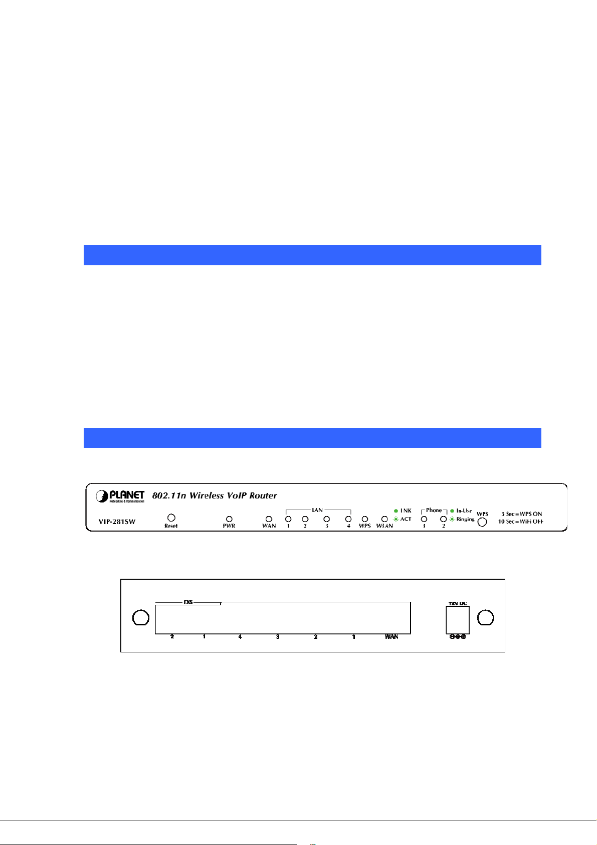
The following figure illustrates the each panel of VIP-281SW
Front Panel of VIP-281SW
Rear Panel of VIP-281SW
- 7 -
Page 8

Physical Interface & Button
Front Panel LED Indicators
LED State Descriptions
PWR
WAN
LAN
WPS
WLAN
Phone
Reset Button
WPS Button
ON
Off
ON
Flashing
Off
ON
Flashing
Off
ON
Off
Flashing
Off
ON
Flashing
Off
Router is power ON
Router is power Off
Router network connection established
Data traffic on cable network
Waiting for network connection
LAN is connected successfully
Data is transmitting
Ethernet not connected to PC
The Wi-Fi Protected Setup function is starting.
The Wi-Fi Protected Setup function is close
Transmitting or receiving data through the Wireless LAN
Wireless LAN is no function
Telephone Set is On-Hook
Ring Indication
Telephone Set is Off-Hook
- Pressing 1 second to reboot machine.
- Pressing 5 seconds to reset to the factory default setting
- Pressing 3 seconds to start the WPS function 2 minutes for client
connection.
- Pressing 10 seconds to enable or disable the wireless function.
Rear Panel Indicators
1 WAN
2 LAN
3 FXS
4 12V DC
5 Antenna
1. Machine LAN port default IP is http://192.168.0.1. Press
Í
Note
RESET button on front panel over 5 seconds will reset the
VoIP Router to factory default value. (Except speed dial and
call forward settings)
2. Using the power supply that is not the one included in package
will cause damage and void the warranty for this product.
RJ-45 connector for Internet access, connected directly to
Switch/Hub through straight CAT-5 cable.
RJ-45 connector, to maintain the existing network structure,
connected directly to the PC through straight CAT-5 cable
RJ-11 connector, connected directly to the analog phone.
12V DC Power input outlet
Used to connect the external antenna for accessing to 802.11b/g/n
wireless network
- 8 -
Page 9
Chapter 2
2
Preparations & Installation
Physical Installation Requirement
This chapter illustrates basic installation of Wireless VoIP Router (“Router” in the following term)
• Network cables. Use standard 10/100Base-TX network (UTP) cables with RJ-45 connectors.
• TCP/IP protocol must be installed on all PCs.
For Internet Access, an Internet Access account with an ISP, and either of a DSL or Cable modem
Administration Interface
PLANET Router provides GUI (Web based, Graphical User Interface) and utility for machine
management and administration.
Web configuration access
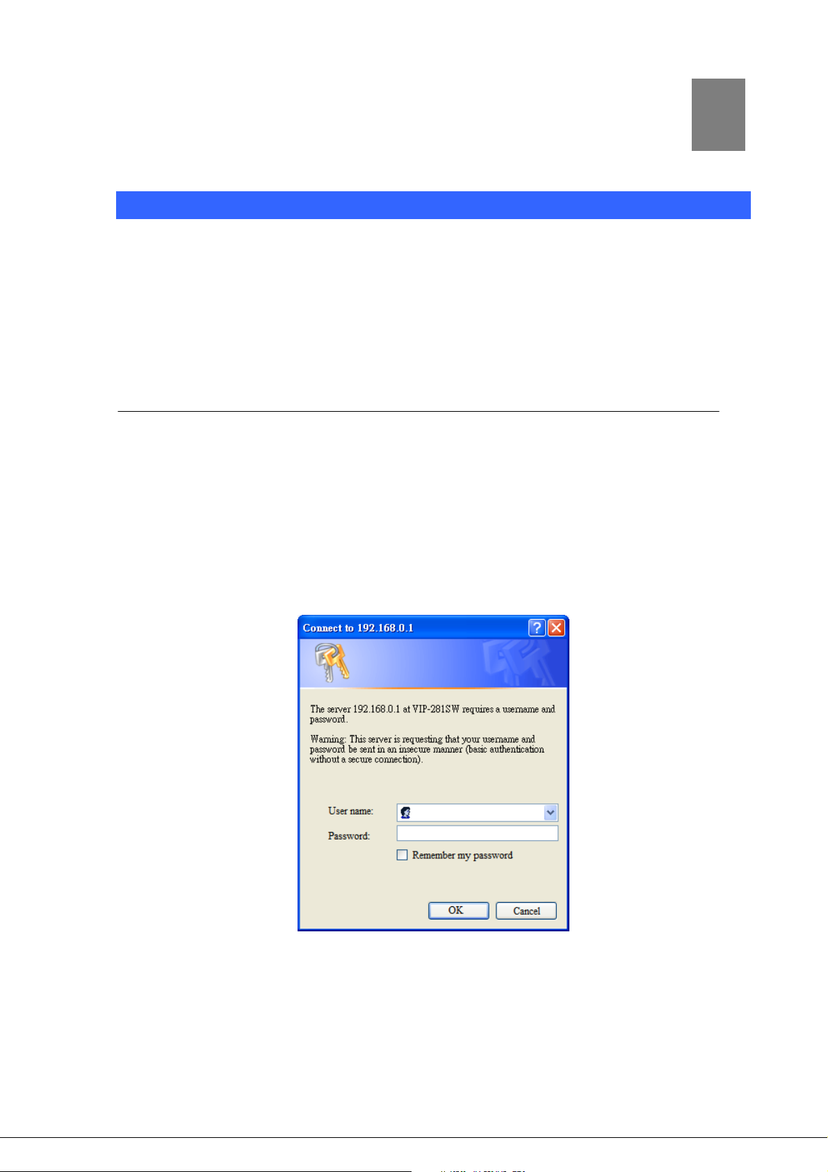
You will connect to SIP Router via your web browser automatically. Router will prompt for logon
username / password, please enter: admin / admin to contin
ue machine administration.
Router will prompt for logon username/password, please enter: admin / admin to continue machine
stration.
admini
- 9 -
Page 10

The default IP address of LAN port is 192.168.0.1. (The WAN port is DHCP client mode.) You also
could open your web browser, and insert http://192.168.0.1 in the address bar of your web browser to
logon Router web configuration page.
To start Router web configuration, you must have one of these web browsers installed on computer for
management
•
Microsoft Internet Explorer 6.00 or higher with Java support
Please locate your PC in the same network segment
Í
Note
(192.168.0.x) of Router. If you’re not familiar with TCP/IP
,
please refer to related chapter on user’s manual CD or
consult your network administrator for proper network
configurations.
Keypad commands
The Router series phone adapters support telephone keypad configurations, please connect analog
telephone set and refer to the following table for machine network configurations.
IVR Menu Choice Machine operation Parameter(s) Notes
#111#
#112xxx*xxx*xxx*
xxx#
#113xxx*xxx*xxx*
xxx#
#114xxx*xxx*xxx*
xxx#
#115xxx*xxx*xxx*
xxx#
#190#
Set DHCP client None
Use the * (star) key
Setup Static IP Address
Set Network Mask
Set Gateway IP Address
Set Primary DNS Server
Unlock None
when entering a decimal
point.
Use the * (star) key
when entering a decimal
point.
Use the * (star) key
when entering a decimal
point.
Use the * (star) key
when entering a decimal
point.
WAN port will change to
DHCP Client
DHCP will be disabled and
system will change to the
Static IP type.
Must set Static IP first.
Must set Static IP first.
Must set Static IP first.
Must unlock the protect
function before carry out
the firmware update
(#160#).
Must save network
#195#
Save Network Settings None
settings after set up
network settings via
keypad.
- 10 -
Page 11

The system will be reset to
#198#
Factory Reset None
factory default value and
reboot automatically.
Following keypad commands can be used to display the network settings enabled on Router via voice
prompt.
IVR Menu Choice Machine operation Notes
#120#
#126#
#121#
#122#
#123#
Check LAN port IP Address
Check WAN port IP Address
Check network connection Type
Check the Phone Number
Check Network Mask
IVR will announce the current IP address of
the LAN port.
IVR will announce the current IP address of
the WAN port.
IVR will announce if DHCP in enabled or
disabled. (WAN port)
IVR will announce current enabled VoIP
number. (WAN port)
IVR will announce the current network mask
of the Router. (WAN port)
#124#
#125#
#128#
Check Gateway IP Address
Check DNS Server Setting
Check Firmware Version
IVR will announce the current gateway IP
address of the Router. (WAN port)
IVR will announce the current setting in the
DNS field. (WAN port)
IVR will announce the version of the
firmware running on the Router.
Following keypad commands can be used to set up the main function .
IVR Menu Choice Machine operation Parameter(s) Notes
01: G.711 u-Law, 02:
#130+first
priority codec
G.711 a-Law, 03: G.729,
04: G.723 6.3K, 05:
G.723 5.3K, 06: G.726
Set First Priority Codec
16K, 07: G.726 24K, 08:
G.726 32K, 09: G.726
40K, 10: GSM-FR, 11:
You can set the codec you
want to the first priority.
For example: #13001#
Set G.711 u-Law to the first
priority codec
G.722
#133#
#134#
#138#
Set Speaker Voice Gain 00~31, 32: Mute
Set Mic Voice Gain 00~31, 32: Mute
Enable call waiting None Enable Call waiting
For example: #13305#
Mic Voice: 5
For example: #13410#
Mic Voice: 10
- 11 -
Page 12

#139#
Disable call waiting None Disable Call waiting
#140+Forward
type+Forward
Phone Number#
#141#
#150#
#160#
Forward Type:
1: Immediate Forward
Forward Settings
2: Busy Forward
3: No answer Forward
Disable Forward Settings None
Select Default Realm 0: Realm 1, 1: Realm 2
Update firmware None
For example: #1401101#
Immediate Forward to 101
For example: #1501#
Set Default Proxy to Realm 2
Update firmware
Must unlock the protect
function (#190#) before carry
out the firmware update.
- 12 -
Page 13

Chapter 3
3
Network Settings
Configuring and monitoring your Router from web browser
The Router integrates a web-based graphical user interface that can cover most configurations and
machine status monitoring. Via standard web browser, you can configure and check machine status
from anywhere around the world.
Overview on the web interface of Router
With web graphical user interface, you may have:
More comprehensive setting feels than traditional command line interface.
Provides user input data fields, check boxes, and for changing machine configuration settings
Displays machine running configuration
To start Router web configuration, you must have one of these web browsers installed on computer for
management
Microsoft Internet Explorer 6.00 or higher with Java support
Manipulation of Router via web browser
Log on Router via web browser
After TCP/IP configurations on your PC, you may now open your web browser, and input
http://192.168.0.1
Enter the IP address of the Router
which by default is 192.168.0.1
Phone Adapter will prompt for logon username/password: admin / admin
(Default LAN port IP address) to logon Router web configuration page.
- 13 -
Page 14
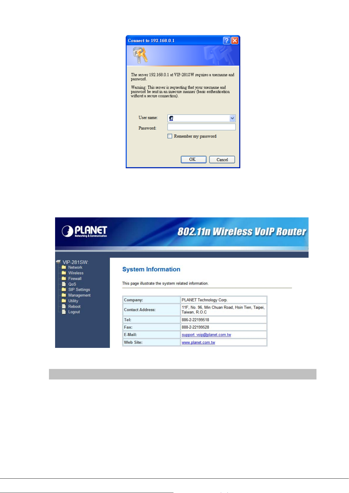
Router login prompt screen
When users login the web page, users can see the general information like company…etc in this main
page.
VoIP Router main page
Network Oprtation Mode
You can setup different modes to WAN and LAN interface for NAT, Bridging and Wireless ISP function
- 14 -
Page 15
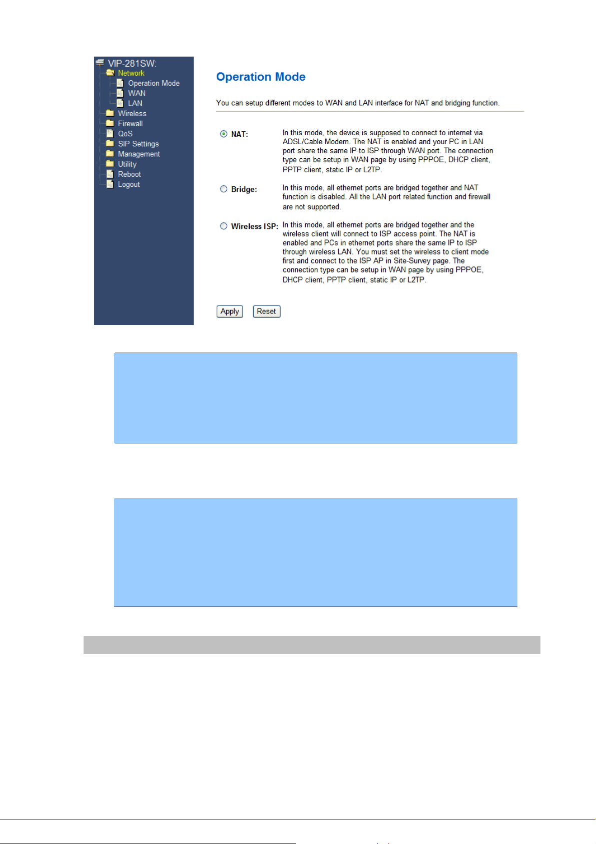
NA T
Bridge
Wireless ISP
In this mode, the device is supposed to connect to internet via
ADSL/Cable Modem. The NAT is enabled and your PC in LAN port
shares the same IP to ISP through WAN port. The connection type
can be setup in WAN page by using PPPOE, DHCP client, PPTP
client, static IP or L2TP.
In this mode, all Ethernet ports are bridged together and NAT function
is disabled. All the LAN port related function and firewall are not
supported.
In this mode, all Ethernet ports are bridged together and the wireless
client will connect to ISP access point. The NAT is enabled and PCs in
Ethernet ports share the same IP to ISP through wireless LAN. You
must set the wireless to client mode first and connect to the ISP AP in
Site-Survey page. The connection type can be setup in WAN page by
using PPPOE, DHCP client, PPTP client, static IP or L2TP.
WAN Interface Setup
This page is used to configure the parameters for Internet network which connects to the WAN port of
your Gateway. Here you may change the access method to static IP, DHCP, PPPoE, PPTP or L2TP by
click the item value of WAN Access type.
- 15 -
Page 16
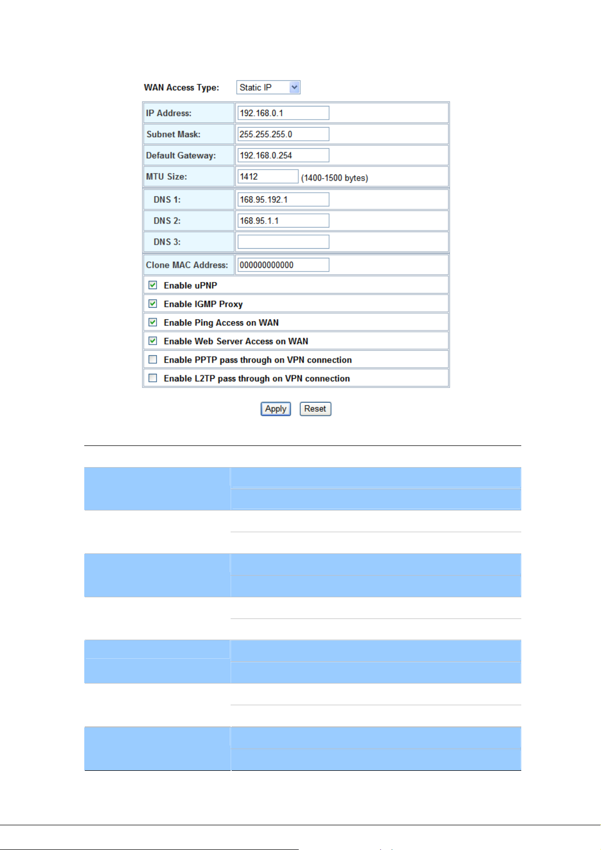
Connection Type Description – Static IP
Static IP
IP Address
Subnet Mask
Default Gateway
MTU Size
DNS1/ 2/ 3
Clone MAC Address
Set WAN interface as Static IP mode.
WAN IP Address of the Router
Default : 192.168.0.1
WAN mask of the Router
Default : 255.255.255.0
Gateway Address of the Router
Default : 192.168.0.254
Set MTU (maximum transmission unit) size
Default : 1412
Set three alternatives Domain Name Server for WAN interface.
Default : Null
To clone the MAC by manual input.
Default : 000000000000 (Null)
Enable UPnP
- 16 -
Check to enable UPnP function
Default : Disable
Page 17
Enable UPnP
Enable IGMP Proxy
Enable Ping Access on WAN
Enable IPSec pass through on
VPN connection
Enable PPTP pass through on
VPN connection
Enable L2TP pass through on
VPN connection
Check to enable UPnP function
Default : Disable
Check to enable the IGMP Proxy function
Default : Enable
If accept ICMP response via WAN port
Default : Enable
If accept be accessed to Web Management Interface via WAN
port
Default : Enable
Check to enable PPTP pass through function
Default : Disable
Check to enable L2TP pass through function
Default : Disable
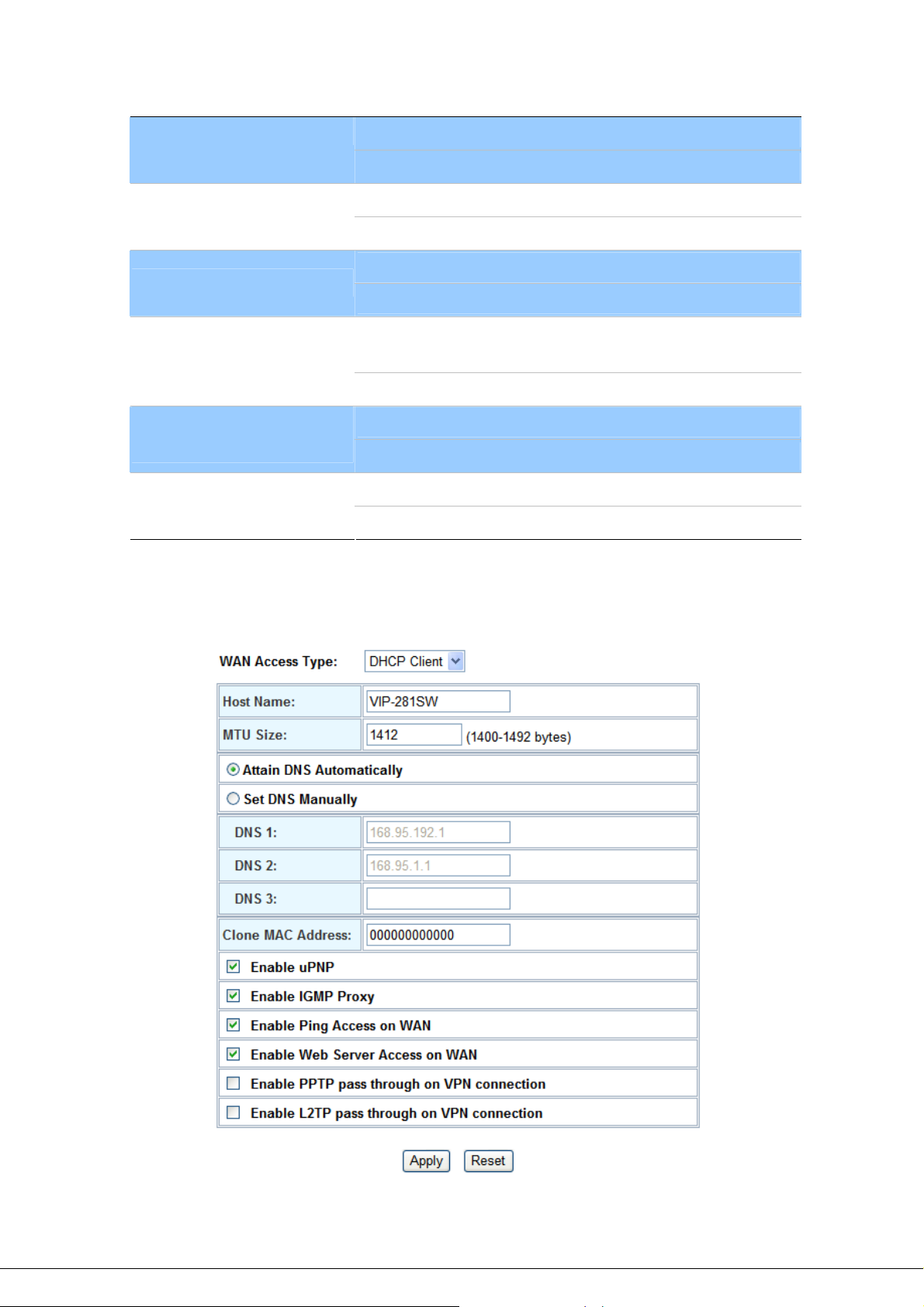
Connection Type Description – DHCP Client
- 17 -
Page 18
DHCP Client
Set WAN interface as DHCP mode.
Attain DNS Automatically /
Set DNS Manually
Select to attain DNS automatically from server or user wants to
set DNS manually.
Default : Set DNS Manually
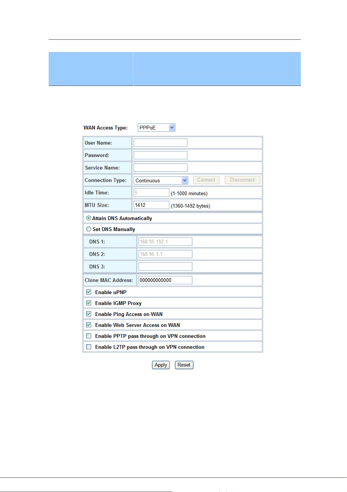
Connection Type Description – PPPoE
- 18 -
Page 19
PPPoE
Set WAN interface as PPPoE mode.
User Name
Password
Service Name
Connection T ype
Idle Time
Set user name of PPPoE connection
Default : Null
Set password of PPPoE connection
Default : Null
Set Service Name of PPPoE for description
Default : Null
Set PPPoE connection type to be Continuous/ Connect on Demand/
Manual. If user set type as Continuous, Router will keep trying to
connect to server when PPPoE disconnect. If user set type as Connect
on Demand, please set following idle time, Router will check
connection after this time. If user set type as Manual, Router will only
connect or disconnect by press Connect or Disconnect manually.
Default : Continuous
Set PPPoE connection idle time for Connect on Demand.
Default : 5
After confirming the modification you’ve done, please click on the Apply button to apply settings
effective and the Router will be reload page automatic by itsely, that you must to afresh enter the final
modification IP address for logon web management.
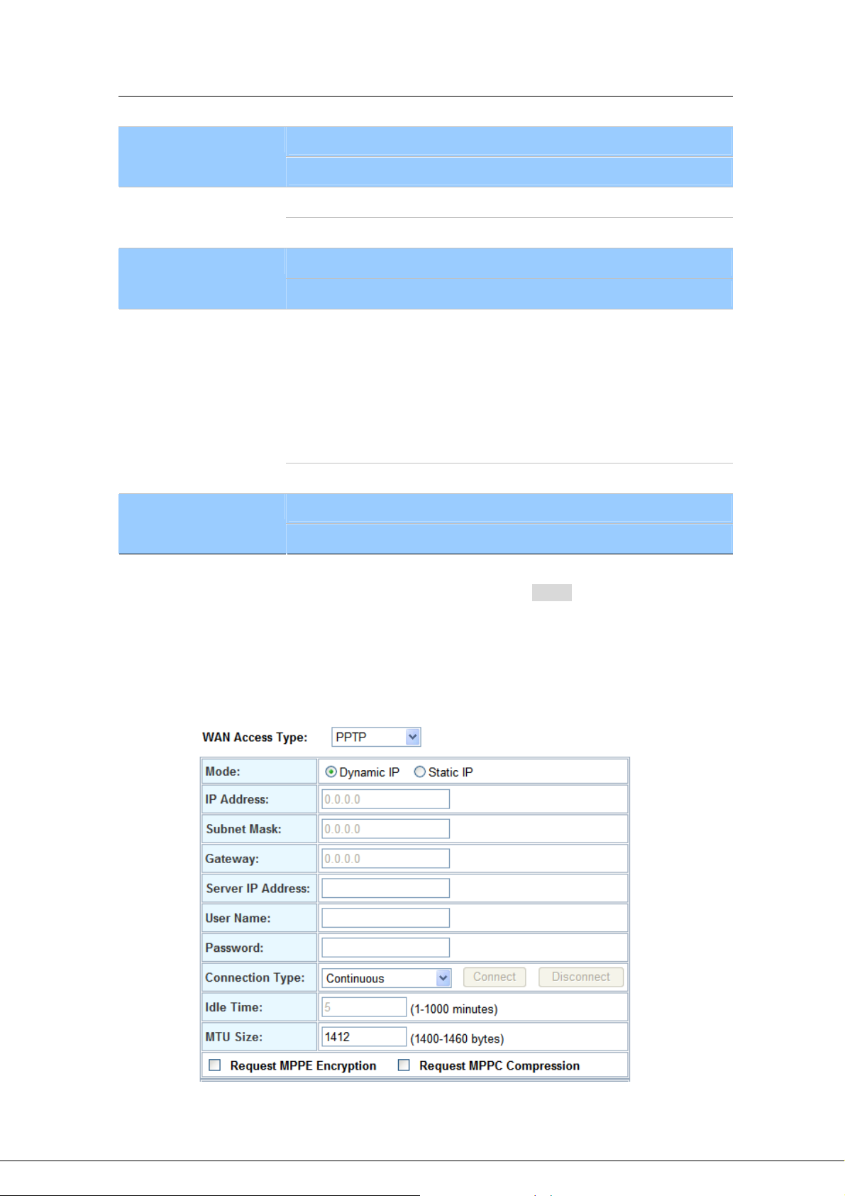
Connection Type Description – PPTP/L2TP
- 19 -
Page 20

PPTP
Set LAN interface as PPTP/L2TP mode.
Mode
IP Address
Subnet Mask
Gateway
Server IP Address
User Name
Password
Set IP type if Dynamic IP or Static IP at PPTP/L2TP connection.
Default : Dynamic IP
WAN IP Address of the Router at Static IP type.
Default : 0.0.0.0
WAN Mask of the Router at Static IP type.
Default : 0.0.0.0
Gateway of the Router
Default : 0.0.0.0
Set PPTP/L2TP Server IP address.
Default : 0.0.0.0
Set user name of PPTP/L2TP connection
Default : Null
Set password of PPTP/L2TP connection
Default : Null
Í
Note
Please be noticed that the Utility Tool is only designed
for the WAN environment setting. If the “Connect Type” is
“PPPoE”, the Utility Tool can NOT find the device.
- 20 -
Page 21
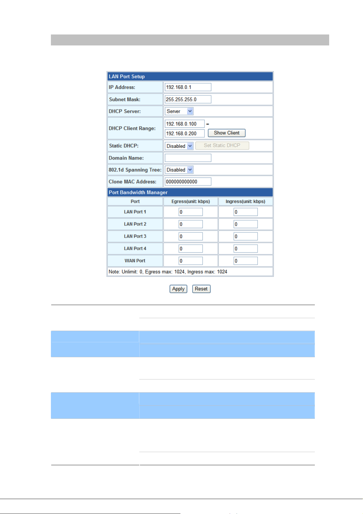
LAN Interface Setup
This page is used to configure the parameters for local area network which connects to the LAN port of
your Gateway. Here you may change the setting for IP address, subnet mask, DHCP, etc..
IP Address
Subnet Mask
DHCP Server
DHCP Client Range
Static DHCP
LAN IP Address of the Router
Default : 192.168.0.1
LAN mask of the Router
Default : 255.255.255.0
You can select Server or Disable. If you select Disable, the
DHCP service of LAN port is disabled.
Default : Server
The first and last IP address that DHCP server assigns.
Default : 192.168.0.100 – 192.168.0.200
It allows you reserve IP addresses, and assign the same IP
address to the network device with the specified MAC address
any time it requests an IP address
Default : Disable
- 21 -
Page 22

Domain Name
Set three alternatives Domain Name Server for LAN interface.
Default : Null
802.11d Spanning Tree
Port Bandwidth Manager
(WAN / LAN ports)
Spanning Tree Protocol. You can select Enable or Disable.
Default : Disable
Show the egress and ingress total network traffic for each WAN
and LAN ports
Default : 0
- 22 -
Page 23
Chapter 4
4
Wireless Settings
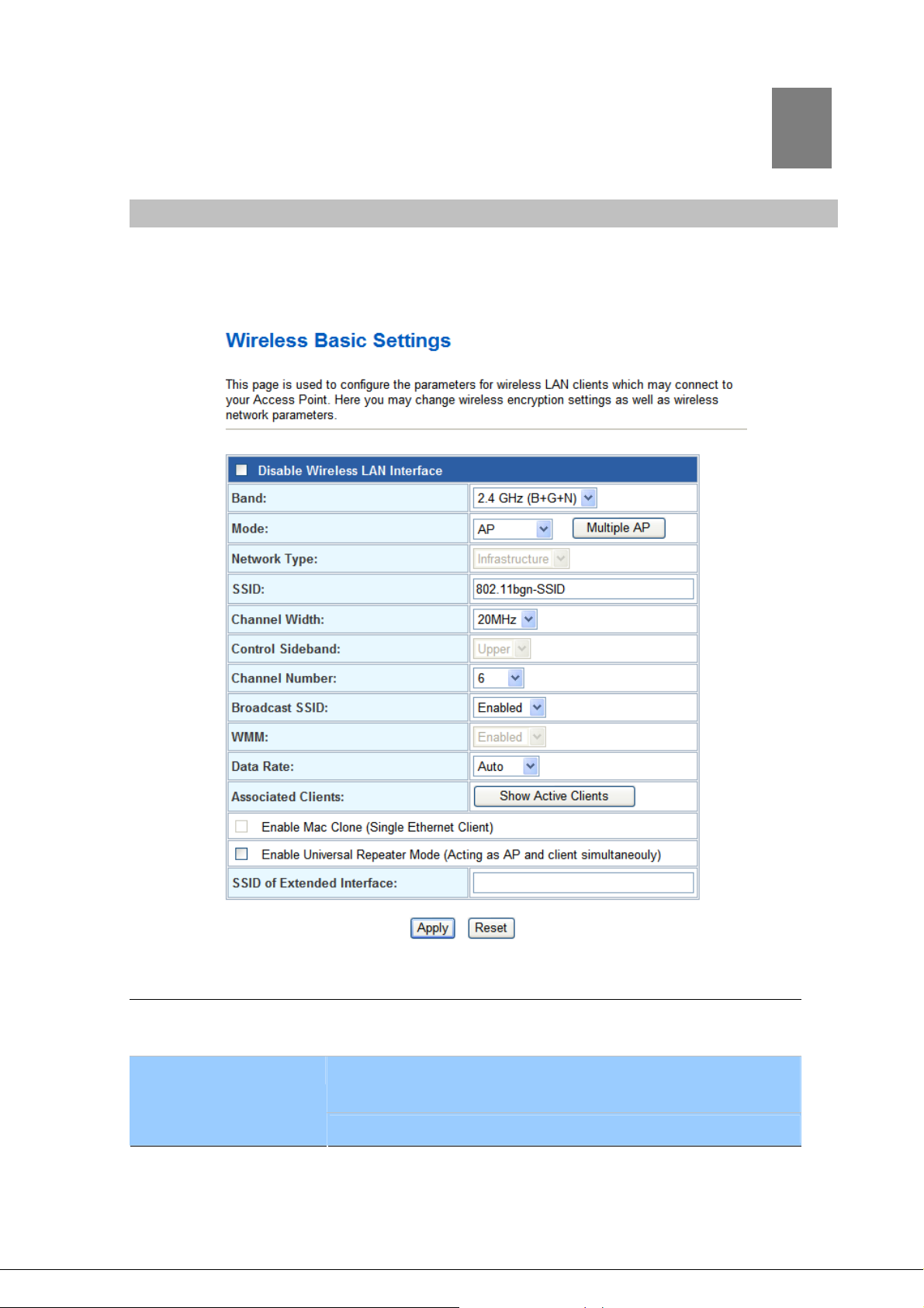
Basic Settings
This page is used to configure the parameters for wireless LAN clients who may connect to your
Access Point. Here you may change wireless encryption settings as well as wireless network
parameters.
Disable Wireless LAN
Interface
Band
- 23 -
Enable or disable the wireless LAN.
There are 6 modes: 2.4GHz (B), 2.4GHz (G), 2.4GHz (N), 2.4GHz
(B+G), 2.4GHz (G+N), and 2.4GHz (B+G+N) mode.
Default : 2.4GHz (B+G+N)
Page 24

Mode
- AP: The AP functions as a wireless hub to which wireless clients
can connect. The clients must make sure that they are configured
to match the AP’s wireless settings. The AP must be connected to
switch or other LAN segment patch cable.
- Client: In this mode the Router is used to access the Wireless
Service Provider network by connecting wirelessly to the remote
(Outdoor AP).
- WDS: WDS operation as defined by the IEEE802.11 standard
has been made available. Using WDS it is possible to wirelessly
connect Access Points, and in doing so extend a wired
infrastructure to locations where cabling is not possible or
inefficient to implement.
- AP+WDS: It means the device can support WDS and AP Mode
simultaneously.
Default : AP mode
Network Type -
SSID
Channel Width
Control Sideband
Channel Number
- Infrastructure: The wireless LAN serves as a wireless station
(infrastructure). Connected to a PC or a small LAN (no more than 5
PCs), it allows the PC or small LAN able to access the wireless
network via Access Point.
- Ad hoc: The wireless LAN will use the Ad hoc mode to operate.
Wireless stations associating to the access point must have the
same SSID. Enter a descriptive name for the wireless LAN.
Default : 802.11bgn-SSID
There are 20MHz and 40MHz bandwidths for cohesion
Default : 20MHz
Specify if the extension channel should be in the Upper or Lower
sideband
Default : Upper (Unavailable)
Select the appropriate channel from the list provided to correspond
with your network settings. Channels differ from country to country.
Default : 6
Broadcast SSID
If you enable “Broadcast ESSID”, every wireless station located
within the coverage of this access point can discover this Router
easily. If you are building a public wireless network, enabling this
feature is recommended. In private network, disabling “Broadcast
ESSID” can provide better security.
Default : Enable
- 24 -
Page 25

WMM
Data Rate
Associated Clients
Enable Mac Clone
Enable Universal
Repeater Mode
The short of Wi-Fi Multi-Media, it will enhance the data transfer
performance of multimedia contents when they’re being transferred
over wireless network.
Default : Enable (Unavailable)
The Data Rate is the rate of data transmission for 802.11b/g/n
clients. The Router will use the highest possible selected
transmission rate to transmit the data packets.
Default : Auto
Default : Auto
To show the MAC address, transmission, reception packet counters
and encrypted status for each associated wireless client.
When set at Client mode, it provides wireless LAN to connect to a
MAC address.
Default : Disable
Universal Repeater is a technology used to extend wireless
coverage.
Default : Disable
SSID of Extended
Interface
Click on “Enable Universal Repeater Mode”; In the “SSID of
Extended Interface”, enter the SSID of the wireless router that you
want to extend.
Default : Null
Advanced Settings
These settings are only for more technically advanced users who have a sufficient knowledge about
wireless LAN. These settings should not be changed unless you know what effect the changes will
have on your Access Point.
- 25 -
Page 26

Fragment Threshold
RTS Threshold
Beacon Interval
Preamble Type
“Fragment Threshold” specifies the maximum size of packet during
the fragmentation of data to be transmitted. If you set this value too
low, it will result in bad performance.
Default : 2346
When the packet size is smaller the RTS threshold, the access point
will not use the RTS/CTS mechanism to send this packet.
Default : 2347
The interval of time that this access point broadcast a beacon.
Beacon is used to synchronize the wireless network.
Default : 100
Preamble type defines the length of CRC block in the frames during
the wireless communication. “Short Preamble” is suitable for high
traffic wireless network. “Long Preamble” can provide more reliable
communication.
Default : Long Preamble
- 26 -
Page 27

A
IAPP
ccess Point Protocol is a recommendation that describes an
Inter-
optional extension to IEEE 802.11 that provides wireless
access-point communications among multivendor systems.
Default : Enable
Protection
Aggregation
Short GI
WLAN Partition
It is recommended to enable the protection mechanism. This
mechanism can decrease the rate of data collision between 802.11b
and 802.11g wireless stations. When the protection mode is enabled,
the throughput of the AP will be a little lower due to many of frame
traffic should be transmitted.
Default : Enable
It is a function where the values of multiple rows are grouped
together.
Default : Enable
It is used to set the time that the receiver waits for RF reflections to
settle out before sampling data.
Default : Enable
This feature also called WLAN isolation or Block Relay. If this feature
is disabled, then there is no barrier between communications among
wireless stations connecting to the Access Point, i.e the Router. If
this is enabled, wireless stations of the selected band are not allowed
to exchange data through the Access Point. The default value is set
to 'Disabled'.
Default : Disable
RF Output Power
Users can adjust the output power to 100%, 75% 50% 35% and
15%.
Default : 100%
Security Setup
This page allows you setup the wireless security. Turn on WEP or WPA by using Encryption Keys could
prevent any unauthorized access to your wireless network.
- 27 -
Page 28

Select SSID
Encryption
802.1x Authentication
If assigned multiple AP feature, you could choose the SSID that want to
setup encryption function.
Select the data privacy algorithm you want. Enabling the security can
protect your data while it is transferred from one station to another.
Default : Disable
Check Box was used to switch the function of the 802.1X. When the
802.1X function is enabled, the Wireless user must authenticate to this
router first to use the Network service.
Default : Uncheck
- WEP
When you select the 128 or 64 bit WEP key security, please select one WEP key to be used and input
26 or 10 hexadecimal (0, 1, 2…8, 9, A, B…F) digits.
- WPA
When select the WPA function, the Wireless user must authenticate to this router first to use the
Network service. RADIUS Server IP address or the 802.1X server’s domain-name.
If you select HEX, you have to fill in 64 hexadecimal (0, 1, 2…8, 9, A, B…F) digits
If ASCII, the length of pre-share key is from 8 to 63.
Key value shared by the RADIUS server and this router. This key value is consistent with the key value in the
- 28 -
Page 29

RADIUS server.
- WPA2
When sele
Network service. RADIUS Server IP address or the 802.1X server’s domain-name.
If you select HEX, you have to fill in 64 hexadecimal (0, 1, 2…8, 9, A, B…F) digits
If ASCII, the length of Pre-share key is from 8 to 63.
Key value shared by the RADIUS server and this rou
RADIUS server.
WPA-Mixed
-
ct the WPA function, the Wireless user must authenticate to this router first to use the
ter. This key value is consistent with the key value in the
When select the W
Network service. RADIUS Server
The router will detect automatically wh
IP address or the 802.1X server’s domain-name.
If you select HEX, you have to fill in 64 hexadecimal (0,
If ASCII, the length of Pre-share key is from 8 to 63.
Key value shared by the RADIUS server and this rou
RADIUS server.
- 29 -
PA-Mixed function, the Wireless user must authenticate to this router first to use the
ich Security type (WPA-PSK version 1 or 2) the client uses to encrypt.
1, 2…8, 9, A, B…F) digits
ter. This key value is consistent with the key value in the
Page 30

Access Control
If you choose 'Allowed Listed', only those clients whose wireless MAC addresses are in the access
control list will be able to connect to your Access Point. When 'Deny Listed' is selected, these wireless
clients on the list will not be able to connect the Access Point.
WDS Settings
Wireless Distribution System uses wireless media to communicate with other APs, like the Ethernet
does. To do this, you must set these APs in the same channel and set MAC address of other APs which
you want to communicate with in the table and then enable the WDS.
- 30 -
Page 31

Site Survey
This page provides tool to scan the wireless network. If any Access Point or IBSS is found, you could
choose to connect it manually when client mode is enabled.
WPS Settings
Wi-Fi Protected Setup (WPS) is the simplest way to build connection between wireless network clients
and this wireless router. You don’t have to select encryption mode and input a long encryption pass
phrase every time when you need to setup a wireless client, you only have to press a button on
wireless client and router, and the WPS will do the rest for you.
This wireless router supports two types of WPS: Push-Button Configuration (PBC), and PIN code. If
you want to use PBC, you have to push a specific button on the wireless client to start WPS mode, and
switch this wireless router to WPS mode too. You can push RET/WPS button of this wireless router, or
click ‘Start PBC’ button in the web configuration interface to do this. If you want to use PIN code, you
can see the setup as below.
- 31 -
Page 32

Disable WPS
WPS Status
Self-PIN Number
Push Button
Configuration
Client PIN Number
Check this box to disable WPS function, uncheck it to enable WPS.
If the wireless security (encryption) function of this wireless router is
properly set, you’ll see ‘Configured’ message here. If wireless
security function has not been set, you’ll see ‘unConfigured’.
This is the WPS PIN code of this wireless router. This code is useful
when router sets as Enrollee, you need to fill this number into the
web page of the other device.
Click ‘Start PBC’ to start Push-Button style WPS setup procedure.
This wireless router will wait for WPS requests from wireless clients
for 2 minutes. The ‘WLAN’ LED on the wireless router will be steady
on when this wireless router is waiting for incoming WPS request.
Please input the PIN code of the other device you wish to connect,
and click ‘Start PIN’ button. The ‘WLAN’ led on the wireless router will
be steady on when this wireless router is waiting for incoming WPS
request. (Please see the detail as below.)
- PBC setup step:
1. Ensure you have set the security setting on Router (as Registrar).
2. Click the WPS button on Router (or the “Start PBC” button on the web interface of Router) and the
other device (supports PBC function) in 2 minutes.
3. Router (Registrar) would send SSID and security key to the other device (Enrollee) through tunnel
to connect.
- 32 -
Page 33

4. If you see the wireless client in the list, WPS-PBC setting is successful.
- PIN (as register) setup step:
1. Select Config Mode: “Registrar” on Router.
2. Fill the PIN code of the other device (as Enrollee that support WPS-PIN setting) into the “configure
via Client Pincode” of Router.
3. Click the PIN buttons on Router and the other device in 2 minutes.
4. If you see the wireless client in the list, WPS-PIN setting is successful.
- PIN (as Enrollee) setup step:
1. Select Config Mode: “Enrollee” on Router.
2. Fill the PIN code of Router into the other device (as Registrar).
3. Click the PIN buttons on Router and the other device in 2 minutes.
4. If you see the wireless client in the list, WPS-PIN setting is successful.
** As the figure as above, just change two roles.
- 33 -
Page 34

Wireless Schedule
This page allows you setup the wireless schedule rule. Please do not forget to configure system time
before enable this feature.
- 34 -
Page 35

Chapter 5
5
Firewall Settings
Port Filtering
Entries in this table are used to restrict certain types of data packets from your local network to Internet
through the Gateway. Use of such filters can be helpful in securing or restricting your local network.
IP Filtering
Entries in this table are used to restrict certain types of data packets from your local network to Internet
through the Gateway. Use of such filters can be helpful in securing or restricting your local network.
- 35 -
Page 36
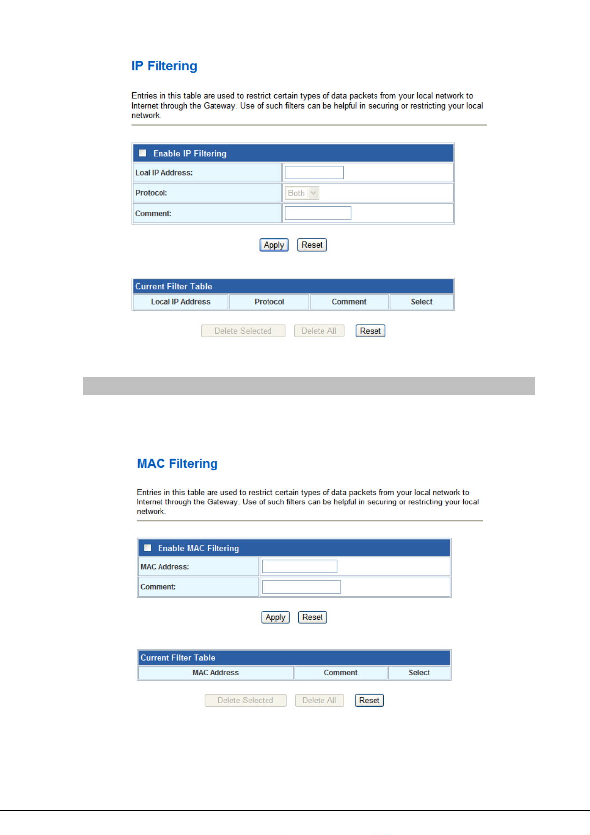
MAC Filtering
You can filter Internet access for local clients based on MAC Address. The MAC address filter enables
you to allow or restrict specified nodes from communicating with other nodes.
- 36 -
Page 37

Port Forwarding
The Port Forwarding allows you to re-direct a particular range of service port numbers (from the
Internet/WAN Ports) to a particular LAN IP address. It helps you to host some servers behind the
firewall.
URL Filtering
URL filter is used to deny LAN port users from accessing the internet. Block those URLs which contain
keywords listed below.
- 37 -
Page 38
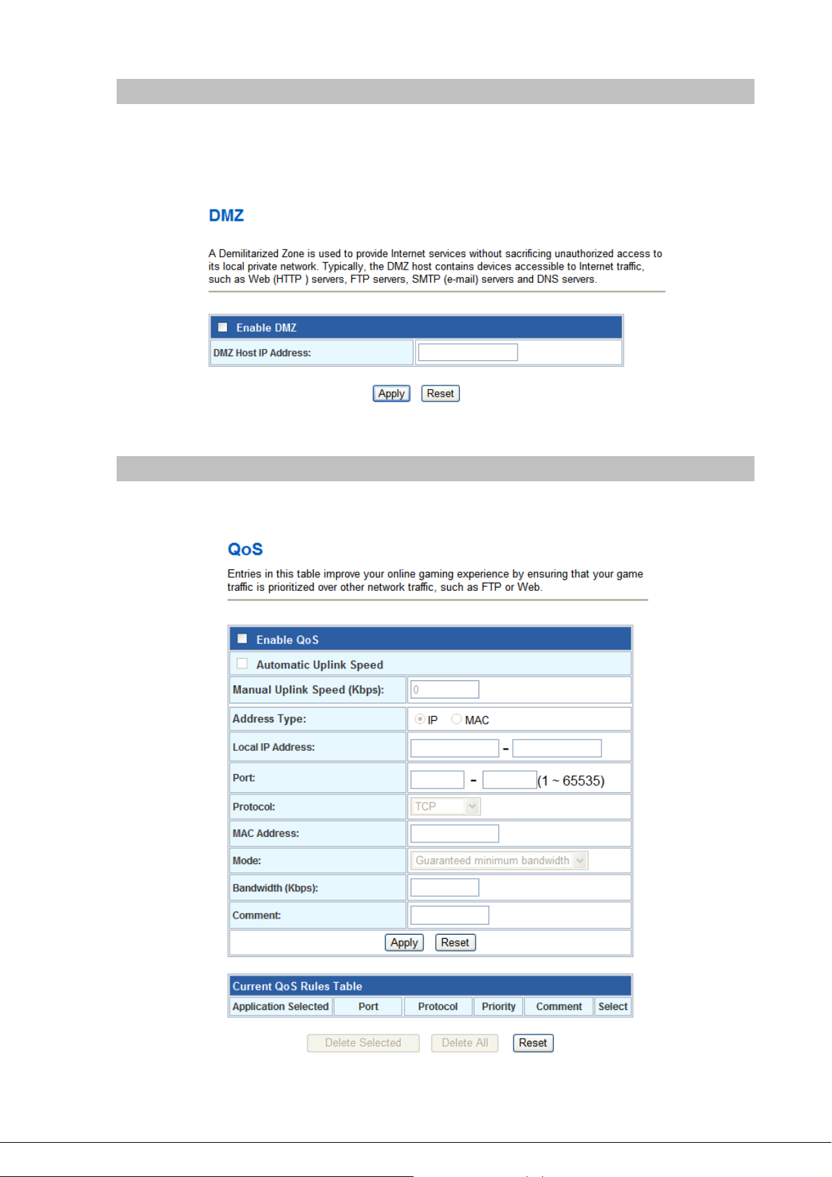
DMZ
A Demilitarized Zone is used to provide Internet services without sacrificing unauthorized access to its
local private network. Typically, the DMZ host contains devices accessible to Internet traffic, such as
Web (HTTP) servers, FTP servers, SMTP (e-mail) servers and DNS servers.
QoS
Entries in this table improve your online gaming experience by ensuring that your game traffic is
prioritized over other network traffic, such as FTP or Web.
- 38 -
Page 39

Chapter 6
6
SIP Settings
Phone 1 / Phone 2
This page is used to configure the parameters for SIP registration information. Here you also could
setup the other functions like Call Forward, Voice Codec, Speed Dial and others.
After finish all the settings, press the
button to cancel the changes.
- Default Proxy
Select Default Proxy
- Realm 1 / Realm 2
Each Phone port has support register two different Proxy
Servers. When select one of Proxy as default, Router will use
this account for making outgoing call. And Router could receive
incoming calls through both Proxys.
Default : Realm1
button to activate the new settings, or press the
- 39 -
Page 40

Display Name
Set Router Phone display name for caller ID information.
Default : Null
Line Number
Register Name
Register Password
Proxy
Proxy Server
Proxy Port
Domain Server
Set registering Phone number.
Default : Null
If Proxy server needs registration authentication please input
Login ID here.
Default : Null
If Proxy server needs registration authentication please input
password here.
Default : Null
Check to enable Proxy mode.
Default : Disable
If user enable Proxy mode, please input Proxy address.
Default : Null
If user enable Proxy mode, please input Proxy port.
Default : 5060
Set SIP domain name for SIP signaling.
SIP Expire Time
Outbound Proxy
Outbound Proxy Server
Outbound Proxy Port
Nortel SoftSwitch
Default : Null
Set expire time of registration. Router will keep re-registering to
proxy server before expire timed out.
Default : 60 (sec)
Check to enable Outbound Proxy mode.
Default : Disable
If user enables Outbound Proxy, please input Outbound Proxy
address.
Default : Null
If user enables Outbound Proxy, please input Outbound Proxy
port.
Default : 5060
Enable this option for better compatibility capability with the
Nortel softswitch.
Default : Disable
Register Status
Here will display SIP account register status.
- 40 -
Page 41

- Call Forward
All Forward
All Fwd No.
Busy Forward
Busy Number
No Answer Forward to
This is unconditional forward setting. All incoming call will be
forwarded to specified number. Check to enable immediate
forward function.
Default : Off
Enter the assigned number for Immediate forward.
Default : Null
Check to enable Busy Forward function. When phone is busy,
incoming call will be forwarded to assigned number.
Default : Off
Enter the assigned number for busy forward.
Default : Null
Check to enable no answer forward function. When phone is not
answered for a period of time, incoming call will be forwarded to
assigned number.
Default : Off
No Answer Number
No Answer Time (sec)
Enter assigned number for no answer forward.
Default : Null
Set no answer time. Once phone is not picked up after this time,
incoming call be will forwarded to assigned number.
Default : 0
- Abbreviated Dial (Phonebook)
- 41 -
Page 42

Abbreviated Name
Phone Number
- Dial Plan
Replace prefix code
Abbreviated Dial (Phonebook) access code. Input this number
and followed by # can dial out assigned phone number.
Set phone number for Router to make speed dial.
Select to enable (On) or disable (Off) prefix replace function.
Default : Off
Relace rule
Dial Plan
- 42 -
Set prefix replace rule. Once user dial number matched prefix,
Router will replace the number with assigned number. Available
parameters are “0~9”, “#”, “*”, “+”, “x”. Symbol “+” means “or” , “x”
could be numbers 0~9. For example, if user set Replace rule as
002+009->005, which means if user dial 002 87654321 or 009
87654321, these number will be dial out as 005 87654321.
Default : Null
User can set how many digits or which number for Router to dial out
immediately. Available parameters are “0~9”, “#”, “*”, “+”, “x”.
Symbol “+” means “or” , “x” could be numbers “0~9”. For example,
user can set Dial Plan as “911+xxxxxxxx+*xx, which means if user
dial 911, 87654321, or *11, these number will be dial out immediately
without waiting for dial time or pressing # sign.
Default : Null
Page 43

Auto Prefix
Prefix Unset Plan
- Speed Dial
If user set Auto Prefix number, all number dialed out will be added
with this prefix number. Available parameters are “0~9”, “#”, “*”.For
example, user set Auto Prefix as 02, number 87654321 will be dial
out as 02 87654321.
Default : Null
User can set special access code to disable Auto Prefix function in
single call. Available parameters are “0~9”, “#”, “*”, “+”, “x”. Symbol
“+” means “or” , “x” could be numbers “0~9”. For example, if user set
Prefix Unset Plan as *1+xxxxxxxxxx. When dialed number as *1
87654321 or 10 digits of number, for this call will not be added with
Auto Prefix number.
Default : Null
Position
Name
Phone Number
Select
Speed Dial access code. Press this speed dial number and
followed by # can dial out assigned phone number.
Name of this speed dial.
Set phone number for Router to make speed dial.
User can delete selected speed dial data.
- 43 -
Page 44

- SIP Advanced
SIP Port
Media Port
DMTF Relay
RFC2833 Payload Type
SIP INFO Duration (ms)
Call Waiting
Call Waiting Caller ID
Set local SIP listening port.
Default : 5060
Set RTP port for sending voice data.
Default : 9000
Select DTMF Relay to be In band, RFC 2833, or SIP INFO.
Default : Inband
If user select DTMF as RFC 2833 type, here can modify RFC
2833 payload type.
Default : 96
If user select DTMF as SIP INFO type, here can modify SIP
INFO duration. Router will send out DTMF as this duration.
Default : 250
Check to enable Call Waiting function.
Default : Enable
Check to enable call waiting caller ID function. If this function is
enabled, caller ID will display when having waiting call. Please
note that your phone set should also support such function.
Default : Disable
Reject Direct IP Call
Check to enable Reject Direct IP Call. If this function is enabled,
Router will to reject the incoming peer to peer call.
Default : Disable
- 44 -
Page 45

- NAT Traversal
Stun
Stun Server Addr
Stun Server Port
- Codec
Check to enable STUN function.
Default : Disable
If user enables STUN function, please input STUN Server
address.
Default : Null
If user enables STUN function, please input STUN Server port.
Default : 3478
Precedence
Rate
Set codec priority sequence.
Set G.723.1 codec with 5.3 or 6.3k mode.
- 45 -
Page 46

- T.38 (FAX)
T.38
T.38 Port
Check to enable T.38 function.
Default : Disable
Set T.38 port for FAX.
Default : 9008
- DSP – Digital Singnal Process Options
- 46 -
Page 47

Vad
Check to enable VAD (Voice Activity Detection) function.
Default : Disable
Caller ID Mode
FSK Date & Time Sync
Reverse Polarity before Caller
ID
Short Ring before Caller ID
Dual Tone before Caller ID
Caller ID Prior First Ring
Caller ID DTMF Start Digit
Select caller ID mode as FSK (Bellcore), FSK (ETSI), FSK (BT),
FSK (NTT), or DTMF from Phone to send out.
Default : DTMF
Check to send FSK Date and Time to caller ID display device.
Default : Disable
Check to send reverse polarity before caller ID.
Default : Disable
Check to send short ring before caller ID.
Default : Disable
Check to send dual tone before caller ID.
Default : Disable
Check to send caller ID before first ring.
Default : Enable
Set caller ID DTMF start digit.
Default : DTMF_A
Caller ID DTMF End Digit
Flash Time Setting (ms)
[ Space:10, Min:30, Max: 2000 ]
Speaker Voice Gain (dB)
[ -32~31 ], Mute:-32
Mic Voice Gain (dB) [ -32~31 ],
Mute:-32
Set caller ID DTMF end digit.
Default : DTMF_C
Set Minimum and Maximum Flash time.
Default : 200 ~ 500
Set Speaker voice volume.
Default : 0
Set microphone voice gain volume.
Default : 0
- Hot Line
- 47 -
Page 48

Use Hot Line
Hot Line Number
Default : Disable
Hot Line Number
- DND (Don’t Disturb)
DND Mode
From
Set the destination number for Hot Line function.
Default : Null
You can select 3 mode of DND. The call will be always rejected if
Always is selected. The call will be rejected by below Time
setting (From and To) if Enable is selected. The call will be
accepted if Disable is selected.
Default : Disable
Set the start time for DND with Enable mode.
To
- Alarm
Enable
Time
Default : 00:00
Set the end time for DND with Enable mode.
Default : 00:00
If set up as Enable, the telephone will ringed up at the specific
time.
Default : Disable
It can set up the system prompt time with 24 hours.
Default : 0:0
- 48 -
Page 49
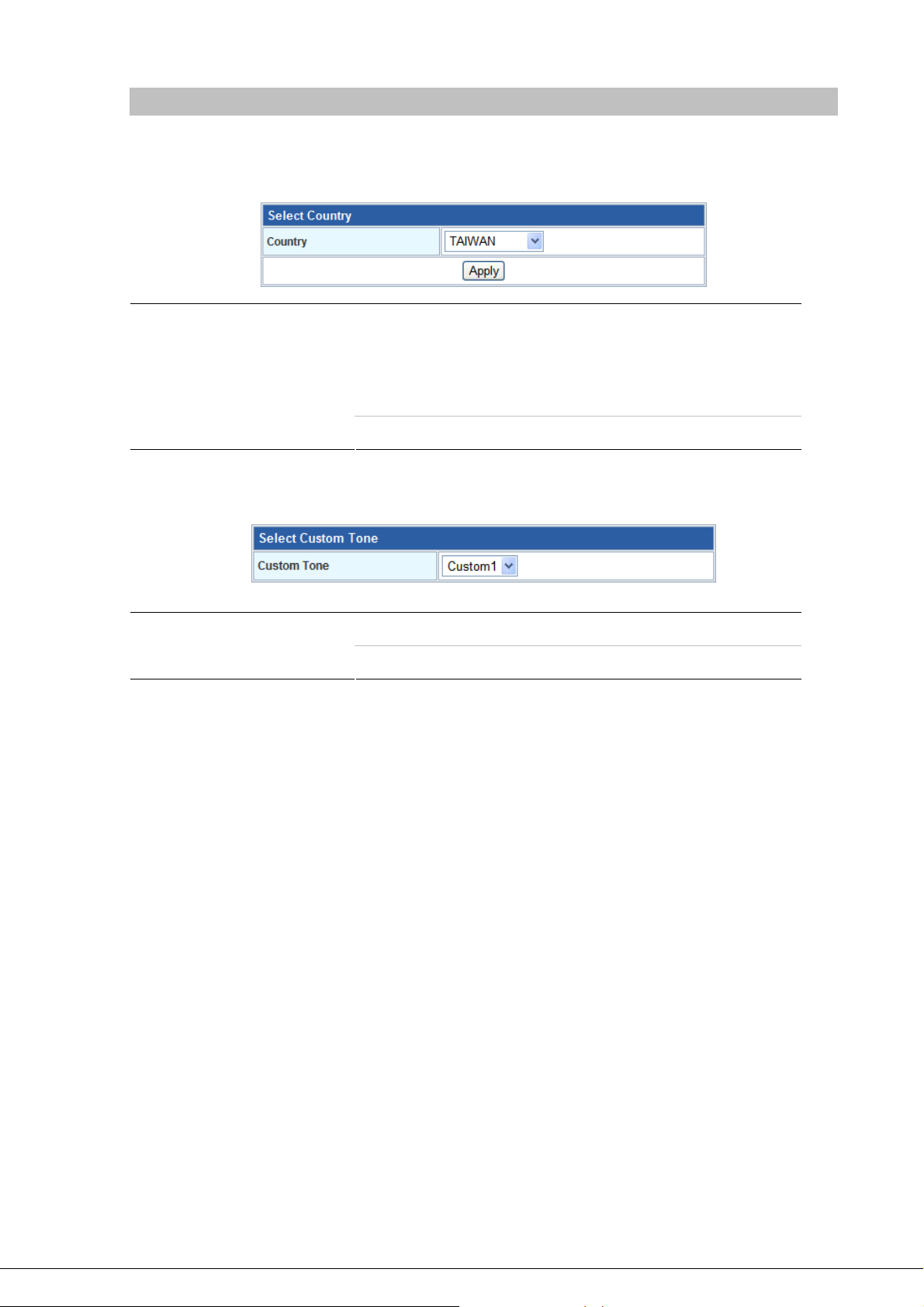
Tone
This page is used to configure the Tone
- Select Country
Country
User can select country to specify tone parameters (Dial Tone,
Ring Tone, Busy Tone, and Waiting Tone). If user wants to set
tone manually, please select CUSTOMER. After selecting
CUSTOMER, user can assign Custom 1 to 8 for each tone.
Default : TAI WAN
Select Country -
Parameters
country, or setup the custom tone parameters.
Custom Tone
Select Custom tone number to set Tone Parameters.
Default : Custom1
- 49 -
Page 50

- Tone Parameters
Freq1
Freq2
Gain1
Gain2
CanOn
Set first set of tone frequency in Hz.
Default : 0
Set second set of tone frequency in Hz. This frequency is
optional.
Default : 0
Set volume level of Freq1 in dB (-7~-10). Please set this
parameter under zero and suggested to set between –7 to –10.
Default : 0
Set volume level of Freq2 in dB (-7~-10). Please set this
parameter under zero and suggested to set between –7 to –10.
Default : 0
Set cadence time for tone to play in ms. For example, if set
CanOn as 100, the tone will be played for 100ms.
Default : 0
- 50 -
Page 51
CanOff
Set cadence time for tone not to play in ms. For example, if set
CanOff as 100, the tone will stop playing for 100ms.
Default : 0
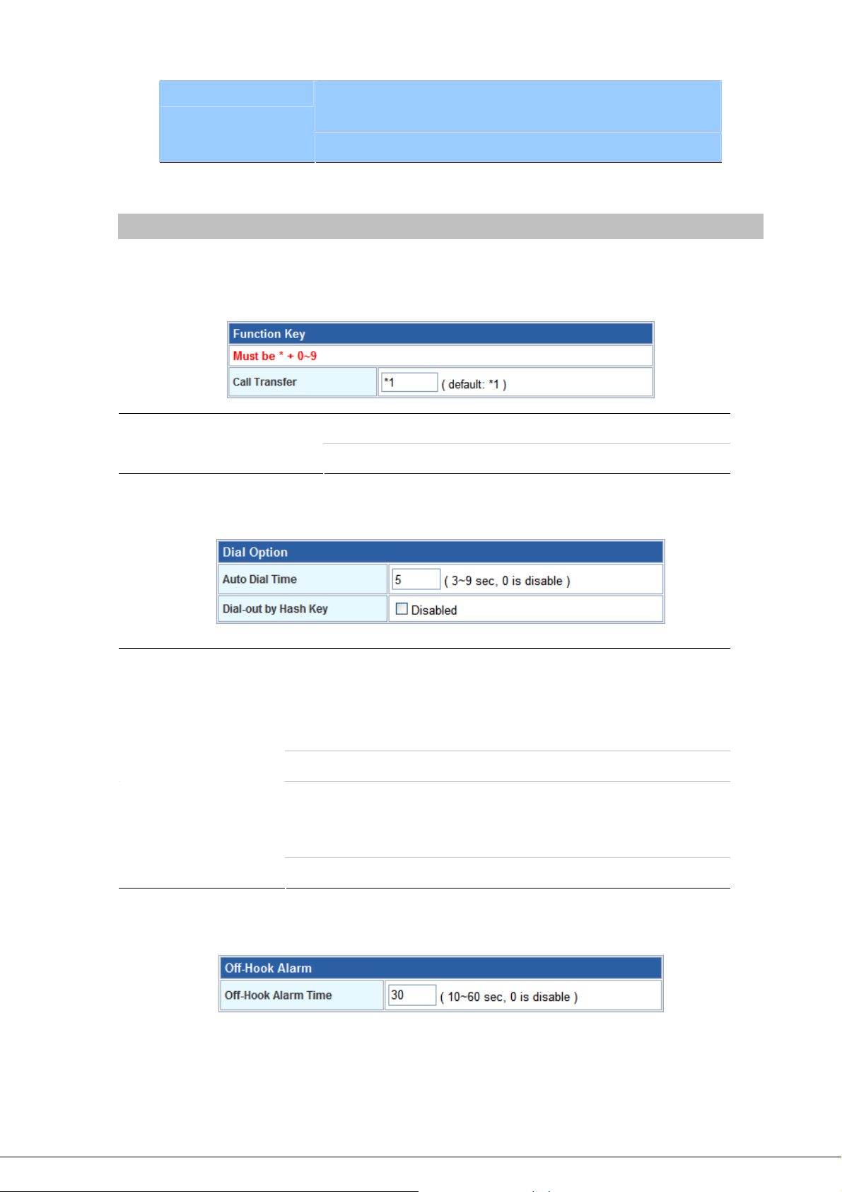
Other
This page is used to configure the function key and other parameters.
- Function Key
Call Transfer
Dial Option -
Auto Dial Time
Dial-out by Hash Key
Set call transfer function key.
Default : *1
Set Auto dial time. When user finish input number after this time,
Router will dial out immediately.
If the call is ended by “#”, the call will be send immediately and you do
not need to wait for the Auto Dial time.
Default : 5
If the “#” symbol is used for other service purpose, it could disable this
option. So that the dialing number could include the “#” symbol and
send to destination side.
Default : Enable
Off-Hook Alarm -
- 51 -
Page 52

Off-Hook Alarm Time
Set off-hook alarm time. If phone set has been off-hook, after this
time, from phone sett will hear alarm.
Default : 30
- FXS Pulse Dial Detection
If your telephone set is pulse type, you can enable this option and define the interdigit pause duration
parameters for operation priority.
SIP QoS
This page is used to configure the parameters for SIP QoS. You can define the DSCP code here for
SIP and RTP. Higher DSCP, higher priority. When DSCP is defined, a DSCP will be added in SIP and
RTP packets, and the priority of voice should be higher than data.
- 52 -
Page 53
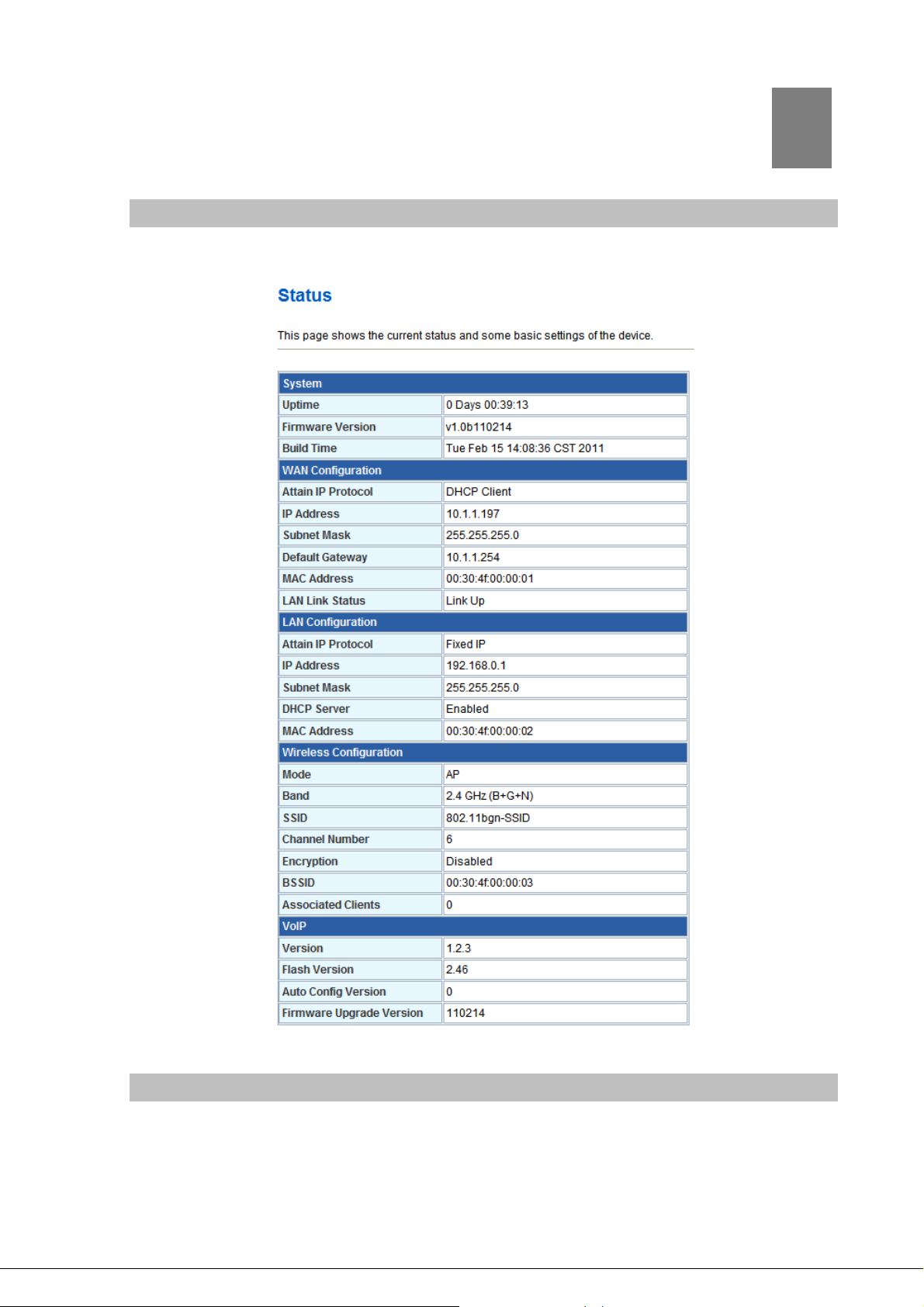
Chapter 7
Management
Status
In this page can show the current status and some basic settings of the Router.
7
Statistics
This page shows the packet counters for transmission and reception regarding to Ethernet networks.
- 53 -
Page 54
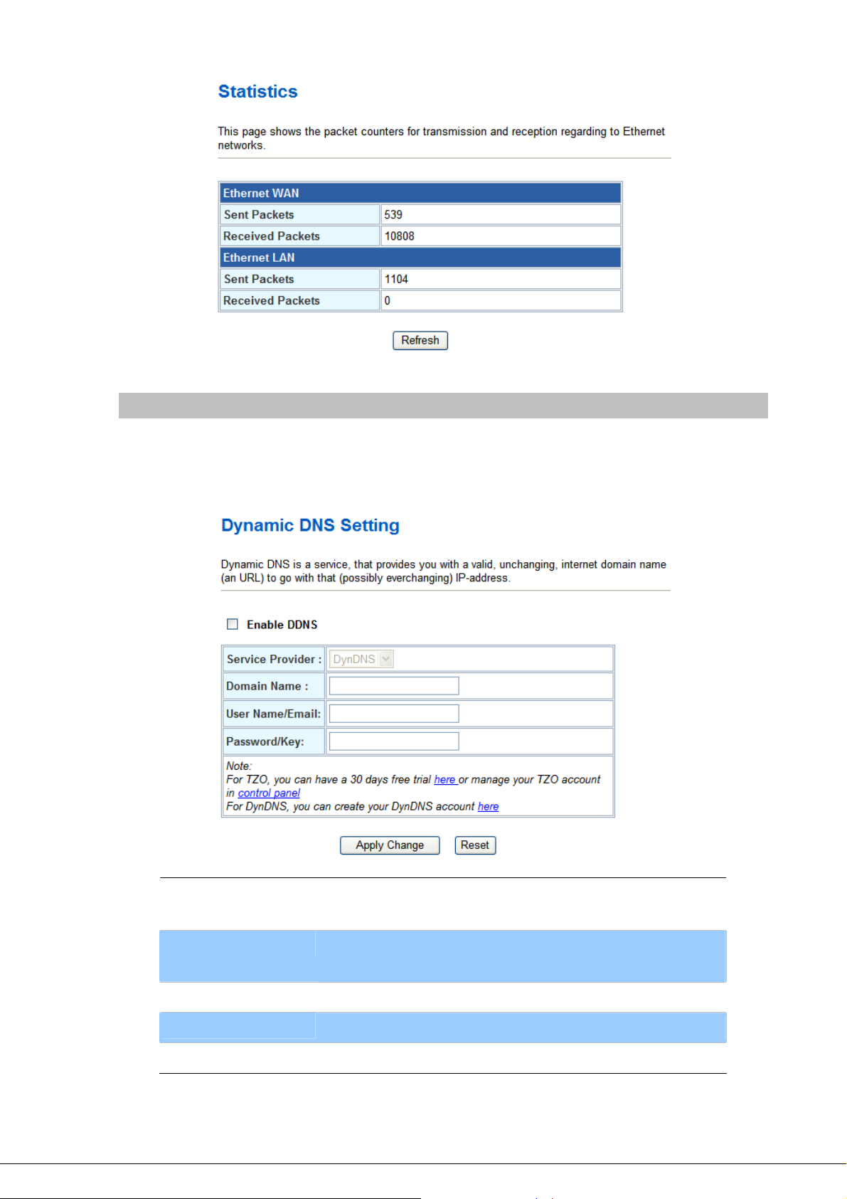
DDNS
Dynamic DNS is a service, which provides you with a valid, unchanging, internet domain name (an URL)
to go with that (possibly ever-changing) IP-address. Before setting this page, you should click below
link to DynDNS or TZO to apply an account for DDNS.
Enable DDNS
Service Provider
Domain Name
User Name/Email
Password/Key
Check to enable DDNS function. User may register to DDNS
server for DDNS function.
Select which server provider to implement DDNS function. For
now we provide two servers: DynDNS and TZO.
Input the applied domain name for Router.
Input user name for DDNS server login.
Input password for DDNS server login.
- 54 -
Page 55

Time Zone Setting
You can maintain the system time by synchronizing with a public time server over the Internet.
Current Time
Input current time manually.
Time Zone Select
Enable NTP client
update
NTP server
Select local time zone according to location.
Check to enable NTP update. Once this function is enabled,
Router will automatically update current time from NTP server.
User may select prefer NTP sever or input address of NTP
server manually.
Denial-of-Service
A "denial-of-service" (DoS) attack is characterized by an explicit attempt by hackers to prevent
legitimate users of a service from using that service.
- 55 -
Page 56
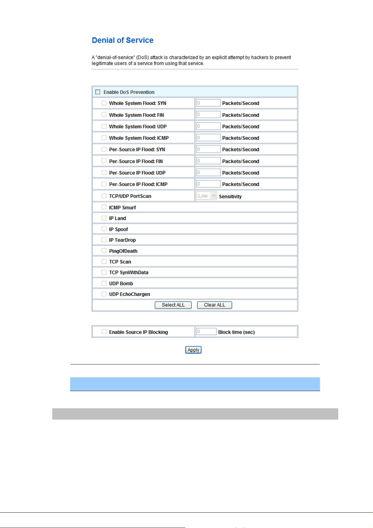
Enable DoS Prevention
User may set other related configurations about DoS below.
Check to enable DoS function.
SNMP Management
This page is used to configure the parameters for SNMP. SNMP is a widely used protocol for
monitoring the health and welfare of network equipment (eg. routers), computer equipment and even
devices like UPSs.
- 56 -
Page 57
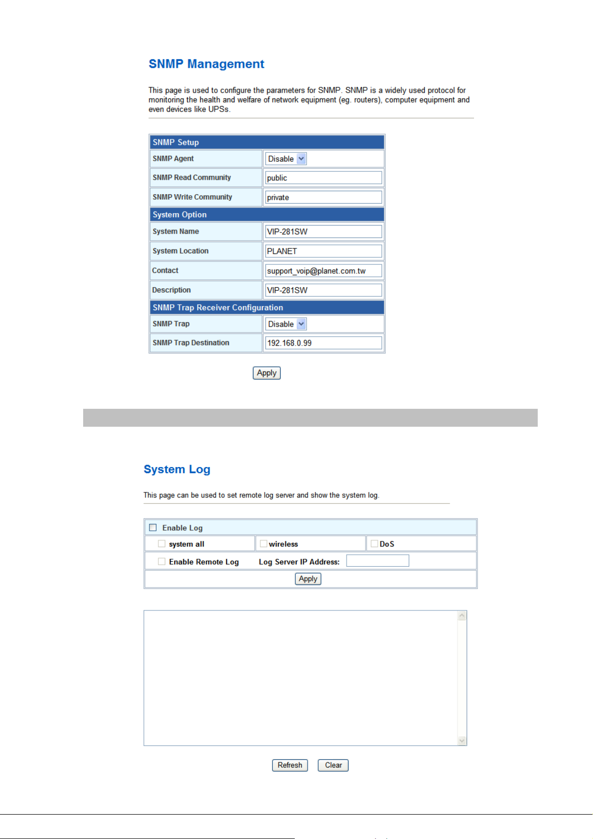
Log
This page can be used to set remote log server and show the system log.
- 57 -
Page 58

Enable Log
Check to enable log function.
System all/Dos
Select which log you want to check. Related information will
be shown at below.
Upgrade Firmware
This page allows you upgrade the Router firmware to new version. Please note, do not power off the
device during the upload because it may crash the system.
Select File
Browse and select file you want to upgrade and press Upload
to perform upgrade.
Please wait till on screen shows related information after
upgrade finished.
Auto Config
This page is used to configure Auto Config and Auto Update.
- Auto Config
Router supports HTTP, TFTP and FTP auto configuration function in total.
- 58 -
Page 59

- Auto Firmware Update
The Router can update new firmware file automatically by the Auto Firmware Update function.
Mode
TFTP Server Address
HTTP Server Address
HTTP File Path
FTP Server Address
FTP Username
FTP Password
FTP Path
There are TFTP / FTP and HTTP three ways to provide the auto
upgrade function.
Input the TFTP Server address, and it could input the IP or
Domain Name form.
Input the HTTP Server address, and it could input the IP or
Domain Name form.
Set up the file path.
Input the FTP Server address, and it could input the IP or
Domain Name form.
The login username.
The login password
Set up the file path.
- 59 -
Page 60

Check new firmware
The Router will according to the below ways to check the new
firmware.
- Power On: The machine will check the new firmware
when power on and following the scheduling date and
time.
- Scheduling: The machine will follow the scheduling date
and time to check the new firmware.
Scheduling Day
Scheduling Time
Automatic Update
File Prefix
Next update time
Firmware Version
Save / Reload Settings
The Router will check the new firmware every the interval time.
The range is 1~30 days.
The Router will check the new firmware between the time range
by random.
There are Notify only and Automatic ways to update.
- Notify only: If there are new firmware, the Router will
send the “Be Be Be” sounds when pick up the handset to
prompt there are new firmware.
- Automatic: The Router will carry firmware update out
automatically.
It will check the information of model name.
It will show the next check date and time.
The current firmware version, the Router is use this value to
decide if there is newer firmware version fo upgrading.
This page allows you save current settings to a file or reload the settings from the file which was saved
previously. Besides, you could reset the current configuration to factory default.
Save Settings to File
Load Settings from File
Reset Settings to Default
Save current settings to a file.
Browse a file and upload to reload settings.
Press Reset will clean all current configurations and return to
default values.
- 60 -
Page 61

Password Setup
This page is used to set the account to access the web server of Router. Empty user name and
password will disable the protection.
User Name
Enter user name.
New Passwor d
Confirmed Password
Input password for this user.
Confirm password again.
- 61 -
Page 62

Chapter 8
8
Utility
Ping Watchdog Setup
This page is used to configure the parameters for Ping Watchdog which pings to IP address every time
interval. System will reboot when failing to ping the IP address 3 times.
Ping Test
This page is used to configure the parameters for Ping Test which pings to IP address or Domain
Name.
- 62 -
Page 63

Traceroute
This page is used to configure the parameters for Traceroute which traces to IP address or Domain
Name.
Reboot
Press Reboot to reboot system. Please wait for a few minutes and reload web page again.
Logout
This page is used to logout.
- 63 -
Page 64

Appendix A Voice communication samples
There are several ways to make calls to desired destination in Router. In this section, we’ll lead you
step by step to establish your first voice communication via keypad and web browsers operations.
Peer to peer (P2P) mode
Assuming there are two routers in the network, the WAN port IP address are 192.168.0.1
and 192.168.0.2
Test the scenario:
1. To Phone A: Other Phone dials “192*168*0*1#”.
2. To Phone B: Other Phone dials “192*168*0*1**5062#”.
3. To Phone C: Other Phone dials “192*168*0*2#”.
4. To Phone D: Other Phone dials “192*168*0*2**5062#”.
L
Hint
y If the IP address of the remote calling party is known,
you may directly make calls by preset number via its IP
address and end with “#”.
y If the VoIP Router is installed behind a NAT/firewall/
IP sharing device, please make sure the NAT device
support SIP applications before making calls.
y The voice communication need to go through via WAN port
of router, so it needs to make sure the WAN port connector
is properly for communication.
- 64 -
Page 65
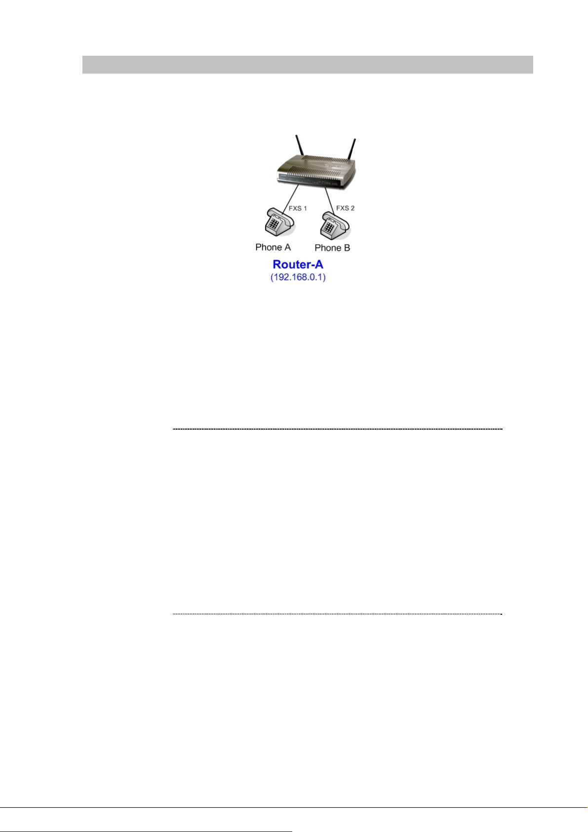
Case 2: (Peer-to-Peer mode) VIP-281SW Port 1 to Port 2 communications
Supposing one VIP-281SW connects to two telephones, just pick up phone 1 and dial
‘192*168*0*1**5062’, phone 2 will ring.
Analog telephone sets are connected to the phone (RJ-11) ports of VIP-281SW respectively
Test the scenario:
1. Pick up the telephone set on Phone 1, and you should be able to hear the dial-tone
2. Press the keypad: 192*168*0*1**5062# shall be able to connect to the Phone 2
3. Then the telephone set in Phone 2 should ring.
4. The Phone 2 also could dial “192*168*0*1#” (without **5062) to Phone 1 to establish the voice
communication.
L
Hint
y If the IP address of the remote calling party is known,
you may directly make calls via its IP address and end
with“#”.
y If the router are installed behind a NAT/firewall/IP
sharing device for Peer-to-Peer VoIP application,
please make sure the NAT device support SIP
applications, and suitable settings should be applied
to the NAT device to enable the SIP communications
before making calls
y [VIP-281SW] in PLANET Router series products, to
connect to remote Router, press the keypad in the
following sequence to connect to the remote VIP-281SW
port 2:
[Remote Router IP address]**5062, for example:
192*168*0*2**5062
- 65 -
Page 66

Case 3: SIP Proxy mode
In this example, there are two Routers register to UMG-2000 via wireless connection. The telephone
set could dial the extension number to each other.
STEP 1:
Log in UMG-2000 and create four testing accounts: 5001 ~ 5004 (password same as number) for
Router-A and Router-B. To enable the Wireless AP Service on UMG-2000 for wireless connection
between Router-A and Router-B.
STEP 2:
Please log in Router-A via web browser, access to “Wireless Basic Settings” page to switch to
Client mode, and fill in the SSID of UMG-2000 (UMG_WIFI). In the setting page, please insert the
account/password information obtained from your service provider (in this sample, we’re using
PLANET UMG-2000 as the IP PBX server for SIP account, call authentications), and then the sample
configuration screen is shown below:
- 66 -
Page 67

It also could access to “Wireless Site Survey” menu to survey the wireless access connection and
connect to UMG-2000.
STEP 3:
To assign the LAN port network parameters as 172.16.0.1 (IP Address) / 255.255.0.0 (Subnet
Mask).
- 67 -
Page 68

STEP 4:
Please log in Router-A via web browser, find to the SIP item. In the setting page, please insert the
account/password information obtained from your service provider (in this sample, we’re using
PLANET UMG-2000 as the IP PBX server for SIP account, call authentications), and then the sample
configuration screen is shown below:
STEP 5:
Repeat the same configuration steps on Router-B, and check the machine registration status,
make sure the registrations are completed.
STEP 6:
To verify the VoIP communication, please pick up the telephone. Dial the destination number to
make call between SIP clients. For example, FXS 1 of Router-A (with number 5001) with keypad
number 5003 to the FXS 1 of Router-B, or reversely makes calls from SIP client (Router-B) to the
number 5001 (FXS 1 of Router-A).
- 68 -
Page 69
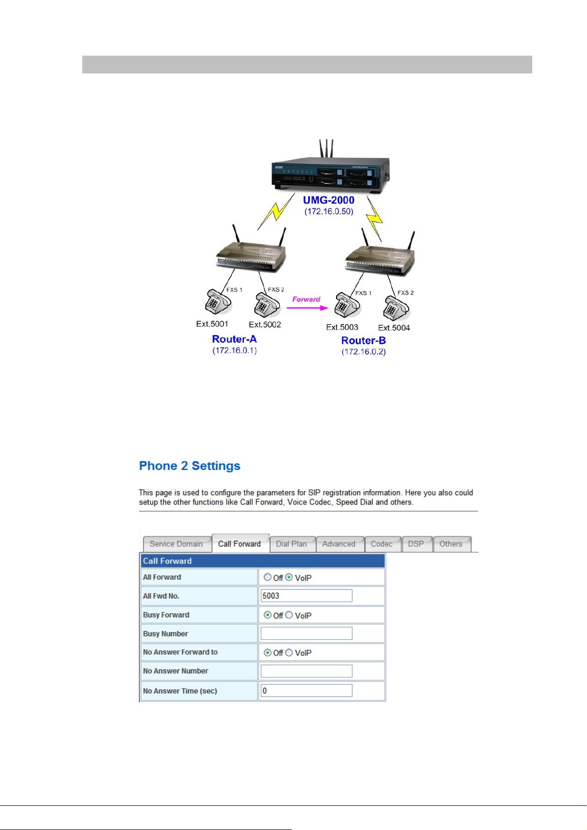
Case 4: Call Forward Feature
In the following samples, we’ll introduce the Call Forward Feature applications.
In this example, both Routers register to UMG-2000 and FXS 2 of Router_A had set Call Forward
function to FXS1 of Router_B.
Machine configuration on the Router:
Please log in Router_A via web browser, browse to the Phone 2 menu and select the Call Forward
config menu. In the setting page, please enable the All Forward function and fill in the number of FXS
1 of Router_B (5003) in All Fwd No. field, then the sample configuration screen is shown below:
Test the scenario:
- 69 -
Page 70

1. FXS 1 of Router_A (ext.5001) pick up the telephone
2. Dial the number 5002 (FXS 2 of Router _A),
3. Because FXS 2 of Router _A had set up All Forward function to the number 5003(FXS 1 of
Router _B)
4. The number 5003 (FXS 1 of Router_B) will ring up then it pick up the telephone and
communication with the number 5001
- 70 -
Page 71

Case 5: VIP-281SW register with IPX-1900 via WAN port
In this example, the VIP-281SW registered with IPX-1900 via WAN port, and has VoIP communications
with VIP-360PT.
STEP 1:
Log in IPX-1900 and create three testing accounts: 101 ~ 103 (password same as number) for
VIP-281SW and VIP-360PT.
STEP 2:
Please log in VIP-281SW via web browser, access to “WAN Interface Setup” page to setup the
WAN port network parameters for connect with IPX-1900.
- 71 -
Page 72

STEP 3:
Please access to the SIP item. In the setting page, please insert the account/password information
obtained from your service provider (in this sample, we’re using PLANET IPX-1900 as the IP PBX
server for SIP account, call authentications), and then the sample configuration screen is shown below:
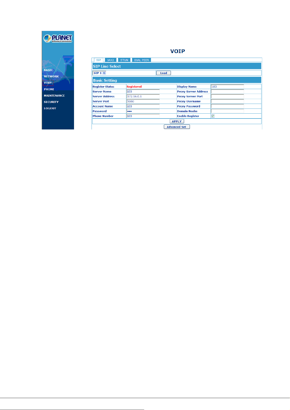
STEP 5:
Please log in VIP-360PT and access to “VOIP” page. According to the SIP account information to
fill in the correspondence fields for registering with IPX-1900.
- 72 -
Page 73
STEP 6:
To verify the VoIP communication, please pick up the telephone. Dial the destination number to
make call between SIP clients. For example, FXS 1 of VIP-281SW with keypad number 103 to the
VIP-360PT. Or reversely makes calls from VIP-360PT SIP client to the number 101 (FXS 1 of
VIP-281SW).
- 73 -
Page 74

Case 6: VIP-281SW register with UMG-2000 via WAN port
In this example, the Router-A and Router-B (VIP-281SW) registered with UMG-2000 via WAN port, and
has VoIP communications with VIP-360PT that registered with LAN port of UMG-2000.
STEP 1:
Log in UMG-2000 and create three testing accounts: 5001 ~ 5005 (password same as number) for
Router-A, Router-B and VIP-360PT.
STEP 2:
Please log in VIP-281SW via web browser, access to “WAN Interface Setup” page to setup the
WAN port network parameters for connect with UMG-2000.
STEP 3:
Please access to the SIP item. In the setting page, please insert the account/password information
- 74 -
Page 75

obtained from your service provider (in this sample, we’re using PLANET UMG-2000 as the IP PBX
server for SIP account, call authentications), and then the sample configuration screen is shown below:
STEP 5:
Please log in VIP-360PT and access to “VOIP” page. According to the SIP account information to
fill in the correspondence fields for registering with UMG-2000.
STEP 6:
To verify the VoIP communication, please pick up the telephone. Dial the destination number to
make call between SIP clients. For example, FXS 1 of Router-A with keypad number 5005 to the
VIP-360PT. Or reversely makes calls from VIP-360PT SIP client to the number 5001 (FXS 1 of
Router-A).
- 75 -
Page 76

Appendix B The method of featured voice operation guide
In this section, we’ll introduce the features method of operation, and lead you step by step to establish
these features.
Call Transfer
A. Blind Transfer
1. B call to A and they are in the process of conversation.
2. A carry the transfer function out (Press *1 button) to hold the conversation with B.
3. A will hear the dial tone then input the number of C (Follow by the “#” key).
4. C will ring up then A hang up the handset.
5. C picks up the handset and conversation with B.
B. Attendant Transfer
1. B call to A and they are in the process of conversation.
2. A carry the transfer function out (Press *1 button) to hold the conversation with B.
3. A will hear the dial tone then input the number of C (Follow by the “#” key).
4. C will ring up.
5. C picks up the handset and conversation with A.
6. A hang up and C conversation with B.
3-Way Conference
1. A and B are in the process of conversation.
2. A want to invite C to join their conversation.
3. A press ”Flash” button on telephone to hold the conversation with B at first and hear the dial
tone, then input the number of C (Follow by the “#” key).
4. C will ring up and pick up the handset to conversation with A.
5. A press ”Flash” button again, and they will entry the 3-Way conference mode.
Call Waiting
1. A and B are in the process of conversation.
2. C call to A and A will hear the prompt sounds.
3. A press ”Flash” button to hold the conversation with B, and switch to conversation with C.
Switch the Default Proxy
Router can register to two different SIP Proxies at the same time. It can receive any one of
different SIP accounts incoming call, and it can switch to any one SIP accounts for making calls through
- 76 -
Page 77

input the switch code.
Realm switch code:
#1500#: Realm 1
#1501#: Realm 2
For example: The default is Realm 1, input the #1501# from keypad and hang up the telephone
set. It will switch to Realm 2 can make the SIP calls via Realm 2.
Auto Update firmware by manual (Keypad)
If pick up the handset of Router, it will hear the “DoDoDo” prompt. If want to carry out the upgrade
action, please input”#190#” to unlock the device at first. Then input”#160#” to upgrade the new
firmware.
- 77 -
Page 78

Appendix C
If your SIP Router is not functioning properly, you can refer to this chapter first for sample
troubleshooting before contacting your dealer. This can save your time and effort but if the symptoms
persist, please consult your dealer.
Frequently Asked Questions List
Q1: I forget my Router login username and / or password
A1:
1.) Restore Router to its factory default settings by pressing the “Reset” button which is at the side
panel of the device for 5 seconds or more.
Q2: Non of the LEDs are on when I turn on the SIP Router
A2:
1.) Check if power cord is connected properly.
2.) Check if there is proper AC power coming from the power outlet.
Q3: Why can’t I dial my friend’s SIP number?
A3:
1.) Check SIP Server Domain Name/IP address. Make sure you have the right Name or IP address.
2.) Check the web browser and access the configuration menu. Make sure that the SIP Server Domain
Name/IP Address is correct.
3.) Check the register status under SIP Account Settings in the configuration menu (from web
browser). If your status is “Not Registered, it means you do not have a SIP account. Contact your
SIP service provider to get an account.
Q4: How to know the machine IP address?
A4:
1.) To pick up the telephone set, and key in #120#.
2.) Machine will prompt the current LAN port IP address.
- 78 -
Page 79

Appendix D Router Specifications
Product 802.11n Wireless VoIP Router
Model VIP-281SW
Hardware
WLAN Standards IEEE 802.11 b/g/n
Wireless Frequency Range 2.4GHz ~ 2.4835 GHz
Wireless Mode AP, Client, WDS and AP+WDS mode
Security
Operating Frequencies /
Channel
Wireless Data Rate
Transmit Power 802.11b: 17dBm, 802.11g: 15dBm, 802.11n: 13dBm
Receiver Sensitivity
Antenna 2 x 2dBi Detachable Antenna
WDS WDS repeater support
WAN 1 x 10/100 Base-TX RJ-45 port
LAN 4 x 10/100 Base-TX RJ-45 port
FXS (for telephone set
connection)
Protocols and Standard
Standard
Voice codec
Fax support* T.38 (G.711 Fax pass-through)
Voice Standard
Protocols
Internet features NAT router, DHCP server, Static routing, Virtual server, Virtual DMZ,
Security Built-in NAT Firewall
Network and Configuration
Access Mode Static IP, PPPoE, DHCP
Configuration &
Management
- 79 -
64/128 bit WEP data encryption, WPA, WPA-PSK, WPA2, WPA2-PSK,
WPA/WPA2 mix mode, 802.1x encryption and WPS PBC
USA/Canada: 2.412 GHz – 2.426 GHz (11 channels)
Europe: 2.412 GHz – 2.472 GHz (13 channels)
Japan: 2.412 GHz – 2.477 GHz (14 channels)
IEEE 802.11b: CCK (11Mbps,5.5Mbps), DQPSK (2Mbps), DBPSK
(1Mbps)
IEEE 802.11g: OFDM (54Mbps, 48Mbps, 36Mbps, 24Mbps, 18Mbps,
12Mbps, 9Mbps, 6Mbps)
IEEE 802.11n: 14/29/43/58/87/116/130/144Mps in 20MHz,
30/60/90/120/180/240/270/300Mbps in 40MHz
802.11b: -86dBm @11M, 802.11g: -72dBm @54M
802.11n (20MHz): -68dBm, 802.11n (40MHz): -66dBm
2 x RJ-11 connection
SIP 2.0 (RFC3261), SDP (RFC 2327), Symmetric RTP, STUN (RFC
3489), , ENUM (RFC 2916), RTP Payload for DTMF Digits (RFC2833),
Outbound Proxy Support, UPnP (UPnPTM)
G.711(A-law /μ-law), G.729 AB, G.723 (6.3 Kbps / 5.3Kbps), G.276
(16,24,32,40 Kbps), GSM and G.722
VAD (Voice Activity Detection)
CNG (Comfort Noise Generation)
G.168: LEC (Line Echo Canceller)
Dynamic Jitter Buffer
In-band and out-of-band DTMF Relay (RFC 2833)
Caller ID Detection/Generation: DTMF, BELLCORE, ETSI, BT, NTT
SIP 2.0 (RFC-3261), TCP/IP, UDP/RTP/RTCP, HTTP, ICMP, ARP,
DNS, DHCP, NTP/SNTP, PPP, PPPoE
Smart QoS, IP ToS (IP Precedance) / DiffServ
MAC / IP / Port Filtering
URL Filtering
Port Forwarding, DMZ
Password protection for system management
Web-Based Graphical User Interface
Remote management over the IP Network
Web-Based firmware upgrade
Backup and Restore Configuration file
Page 80

SNMP v1/v2, Auto-Provision, Keypad on telephone set
Dimension (W x D x H) 186 x 143 x 35 mm
Operating Environment 0~50 Degree C, 5~90% humidity
Power Requirement 12V DC
EMC/EMI CE, FCC Part 15 Class B
- 80 -
 Loading...