

Page 1
SIP IP Phone
VIP-256T
SIP IP Phone
VIP-256T
1
Page 2

SIP IP Phone
VIP-256T
Copyright
Copyright (C) 2013 PLANET Technology Corp. All rights reserved.
The products and programs described in this User’s Manual are licensed products of PLANET Technology. This User’s
Manual contains proprietary information protected by copyright, and this User’s Manual and all acc ompanying hardware,
software, and documentation are copyrighted.
No part of this User’s Manual may be copied, photocopied, reproduced, translated, or reduced to any electronic medium or
machine-readable form by any means by electronic or mechanical, including photocopying, recording, or information
storage and retrieval systems, for any purpose other than the purchaser's personal use, and without the prior express
written permission of PLANET Technology.
Disclaimer
PLANET Technology does not warrant that the hardware will work properly in all environments and applications, and
makes no warranty and representation, either implied or expressed, with respect to the quality, performance,
merchantability, or fitness for a particular purpose.
PLANET has made every effort to ensure that this User’s Manual is accurate; PLANET disclaims liability for any
inaccuracies or omissions that may have occurred.
Information in this User’s Manual is subject to change without notice and does not represent a commitment on the part of
PLANET. PLANET assumes no responsibility for any inaccuracies that may be contained in this User’s Manual. PLANET
makes no commitment to update or keep current the information in this User’s Manual, and reserves the right to make
improvements to this User’s Manual and/or to the products described in this User’s Manual at any time without notice.
If you find information in this manual that is incorrect, misleading, or incomplete, we would appreciate your comments and
suggestions.
CE mark Warning
This is a class B device. In a domestic environment, this product may cause radio interference, in which case the user may
be required to take adequate measures.
Energy Saving Note of the Device
This power required device does not support Stand by mode operation. For energy saving, please rem ove the D C-plug or
push the hardware Power Switch to OFF position to disconnect the device from the power circuit. Without removing the
DC-plug or switching off the device, the device will still consume power from the power circuit. In view of saving the energy
and reducing the unnecessary power consumption, it is strongly suggested to switch off or remove the DC-plug for the
device if this device is not intended to be active.
2
Page 3

SIP IP Phone
VIP-256T
WEEE Warning
To avoid the potential effects on the environment and human health as a result of the presence of hazardous
substances in electrical and electronic equipment, end users of electrical and electronic e quipment should
understand the meaning of the crossed-out wheeled bin symbol. Do not dispose of WEEE as unsorted
municipal waste; they should be collected separately.
Trademarks
The PLANET logo is a trademark of PLANET Technology. This documentation may refer to numerous hardware and
software products by their trade names. In most, if not all cases, their respective companies claim these designations as
trademarks or registered trademarks.
Revision
User’s Manual for PLANET SIP IP Phone:
Model: VIP-256T
Rev: 1.1(2013 March)
Part No. EM-VIP-256T_v1.1
3
Page 4

SIP IP Phone
VIP-256T
Table of Contents
Chapter 1Introduction....................................................................................6
Overview...................................................................................................................................... 6
Product Features....................................................................................................................... 10
Specifications..............................................................................................................................11
Package Content........................................................................................................................ 13
Physical Details.......................................................................................................................... 13
Front View and Keypad function........................................................................................ 13
Rear V iew............................................................................................................................ 14
Phone Screen Features........................................................................................................ 15
Chapter 2 Preparations & Installation.........................................................17
Physical Installation.................................................................................................................. 17
Administration Interface.......................................................................................................... 19
Web configuration access.................................................................................................... 19
Chapter 3 Network Service Configurations................................................20
Configuring and monitoring your IP Phone from web browser........................................... 20
Manipulation of IP Phone via web browser........................................................................ 20
Chapter 4 VoIP IP Phone Status ..................................................................21
Status .......................................................................................................................................... 21
Basic.................................................................................................................................... 21
DHCP.................................................................................................................................. 23
Syslog.................................................................................................................................. 23
Chapter 5 SIP Account Setting....................................................................25
SIP Account................................................................................................................................25
SIP setting........................................................................................................................... 25
NAT setting......................................................................................................................... 26
Line settings............................................................................................................................... 27
Basic.................................................................................................................................... 27
Audio Configuration........................................................................................................... 28
Supplementary Services Subscription................................................................................. 29
Advanced ............................................................................................................................ 29
Chapter 6 Network Setting...........................................................................31
Basic ........................................................................................................................................... 31
Internet Port (WAN)............................................................................................................ 32
PC Port(LAN)..................................................................................................................... 34
Network Address Server Settings (DHCP)......................................................................... 35
MAC Address Clone ................................................................................................................. 36
4
Page 5

SIP IP Phone
VIP-256T
VPN ............................................................................................................................................ 37
DMZ........................................................................................................................................... 38
QoS............................................................................................................................................. 39
Chapter 7 Phone Configurations.................................................................40
Performance .............................................................................................................................. 40
Volume ................................................................................................................................ 40
Regional.............................................................................................................................. 41
Call Forward ....................................................................................................................... 42
Miscellaneous ..................................................................................................................... 42
Multi-Functional Key ............................................................................................................... 43
Dial Plan..................................................................................................................................... 45
Phonebook ................................................................................................................................. 49
Phonebook........................................................................................................................... 49
Black List............................................................................................................................ 50
Call Log .............................................................................................................................. 51
Chapter 8 VoIP IP Phone Administration....................................................52
Management.............................................................................................................................. 52
Time/Date............................................................................................................................ 52
Password Reset ................................................................................................................... 54
W eb Access......................................................................................................................... 55
System Log Setting............................................................................................................. 55
Factory Defaults.................................................................................................................. 57
Update Firmware......................................................................................................................57
Security ...................................................................................................................................... 57
Provision .................................................................................................................................... 59
SNMP......................................................................................................................................... 62
TR 069........................................................................................................................................ 63
Appendix A Frequently Asked Questions List............................................64
5
Page 6

SIP IP Phone
VIP-256T
Chapter 1
Introduction
Overview
Cost-effective, High-performance VoIP Phone
To build high-performance VoIP communications at a low co st, PLANET now introduces the latest member of
its IP Phone family, the VIP-256T 2-Line Business IP Phone. The VIP-256T makes it simple for the enterprise
featuring voice and data system or expanding voice system to new locations. It helps the company to save
money on long distance calls; for example, the remote workers can dial in throug h a Unified VoIP
Communication System just like an extension call but no long dist ance ch arge would occur. The VIP-256T also
allows call to be transferred to anyone at any location within the voice system, which enables the enterprise to
communicate more effectively and is help f ul to streamline business processes.
1
6
Page 7
SIP IP Phone
VIP-256T
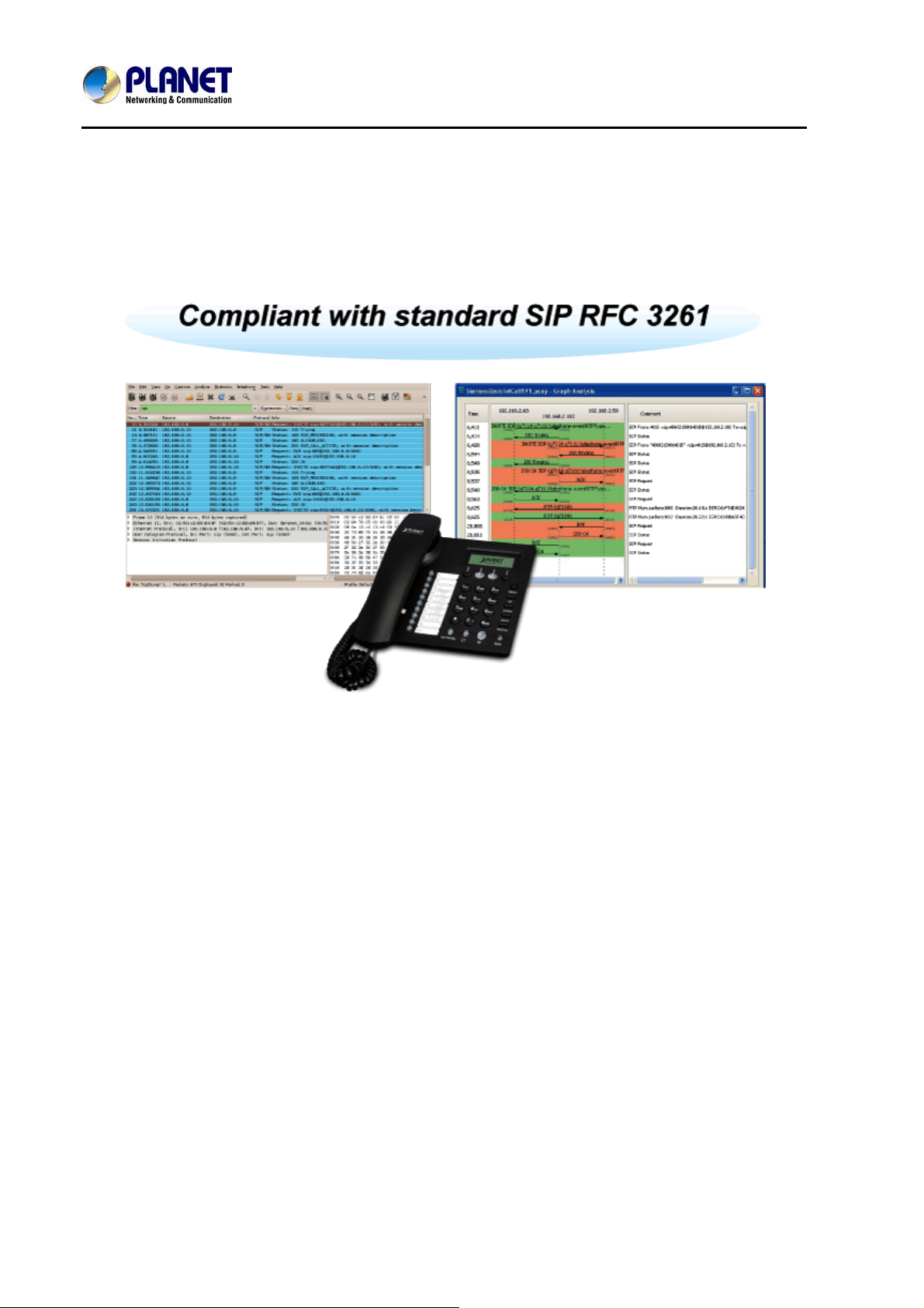
Standard Compliance
Compliant with the Session Initiation Protocol 2.0 (RFC 3261), the VIP-256T is able to broadly interoperate
with equipment provided by VoIP infrastructure providers, thus enabling them to provide their customers with
better multi-media exchange servies.
Enhanced, Full-Featured Busine
ss IP Phone
The VIP-256T is a full-featured enhanced business IP Phone that addresses the communication needs of the
enterprises. It provides 2 voice lines and dual 10/100Mbps Ethernet. Furthermore, the VIP-256T delivers
user-friendly design containing a 128×32 Grap hic LCD with white backlig ht, 2 line keys and 4 sof t keys, and 10
multi-functional keys with dual-color LED. The VIP-256T supports all kinds of SIP based phone features
including Call Waiting, Auto Answer, Music on Hold, Caller ID and Call Waiting ID, 3-way Conferencing, Call
Hold, Call Forwarding, Black List, Hotline, DTMF Relay, In-Band, Out-of-Band (RFC 2833) and SIP INFO,
among others. Besides for office use, the VIP-256T is also the ideal solution for VoIP service offered by
Internet Telephony Service Provider (ITSP).
7
Page 8
SIP IP Phone
VIP-256T
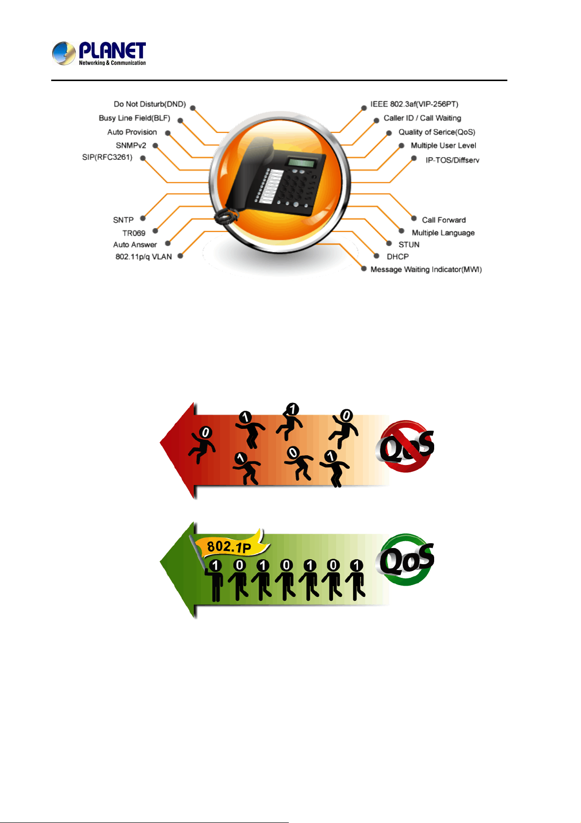
Secure, High-Quality V
The VIP-256T supports SIP v2 for easy integration with general voice over IP system. It can also effortlessly
deliver secured toll voice quality by utilizing cutting-edge 802.1p QoS (Quality of Service), 802.1Q VLAN
tagging, and IP ToS technology.
oIP Communication
8
Page 9
SIP IP Phone
VIP-256T
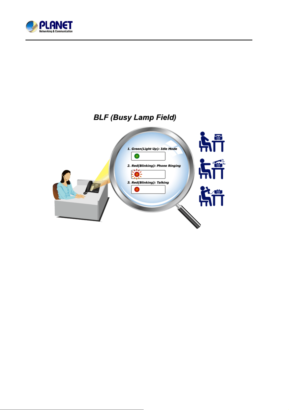
Professional Application
The VIP-256T supports Busy Lamp Field (BLF) function that, via the lights on the phone, enables users to
easily identify the status of other phones which are connected to the same IP PBX, such as busy, idle, ringing,
etc. The connected IP PBX must also support BLF feature. The BLF function is helpful for a receptioni st on the
front desk to route all incoming calls smoothly.
9
Page 10

SIP IP Phone
VIP-256T
Product Features
¾ Highlights
2-Line enterprise-class IP phone
Connects directly to an Internet telephone service provider or to an IP PBX
Dual switched Ethernet ports, speakerphone, caller ID, call hold, conferencing, and more
Easy installation and highly secure remote provisioning, as well as menu-based and web-based configuration
¾ Telephony Features
Two Voice Lines
Pixel-based Display: 128 x 32 monochrome graphical liq uid crystal display (LCD)
Caller ID and Call Waiting ID
3-way Conferencing
SMS Functions
Busy Lamp Field (BLF)
Do Not Disturb (DND)
Full-Duplex Speakerphone
Call Transfer: Blind Transfer and Attended Transfer
Call Mute, Redial, Speed Dial, Pick Up, Call Park, Dial Plan, Call Hold, Call Forwarding
¾ Management
SIP v2 (RFC 3261, 3262, 3263, 3264)
STUN (RFC 3489)
Automated provisioning and upgrade via HTTPS, HTTP, TFTP
Message Waiting Indicator (RFC 3842)
IEEE 802.1Q VLAN / 802.1p and IP ToS
TR069 / SNMP v2
10
Page 11

SIP IP Phone
Specifications
Product
Hardware
Lines (Direct Numbers)
Display
Feature Keys
Physical Interfaces
Protocols and Standard
Data Networking
Voice Gateway
Provisioning, Administration,
and Maintenance
Features
Telephony Features
VIP-256T
VIP-256T
SIP IP Phone
2-Line Enterprise-class IP phone
128x32 Graphic LCD with White Backlight
2 Line Keys and 4 Soft Keys
12 Dialing Buttons (0~9, *, #)
9 Fixed Function Buttons
10 Multi-functional Key with Dual-Color LED
Two 10/100BASE-T RJ-45 Ethernet Ports (IEEE 802.3)
Handset: RJ-9 Connector
Built-in Speakerphone and Microphone
MAC Address (IEEE 802.3)
IPv4 (RFC 791)
Address Resolution Protocol (ARP)
DNS: A Record (RFC 1706), SRV Record (RFC 2782)
Dynamic Host Configuration Protocol (DHCP) Client (RFC 2131)
Internet Control Message Protocol (ICMP) (RFC 792)
TCP (RFC 793)
User Datagram Protocol UDP (RFC 768)
Real Time Protocol RTP (RFC 1889, 1890)
Real Time Control Protocol (RTCP) (RFC 1889)
Differentiated Services (DiffServ) (RFC 2475)
Type of Service (ToS) (RFC 791, 1349)
VLAN Tagging 802.1p / 802.1Q: Layer 2 Quality of Service (QoS)
Simple Network Time Protocol (SNTP) (RFC 2030)
Backward Compatible with RFC 2543
Session Timer (RFC 4028)
SDP (RFC 2327)
NAPTR for SIP URI Lookup (RFC 2915)
SIP Version 2 (RFC 3261, 3262, 3263, 3264)
SIP supported in NAT Metworks [including STUN (RFC 3489)]
Message Waiting Indicator (RFC 3842)
Voice Algorithms:
- G.711 (A-law and μ-law)
- G.726 (16/24/32/40 kbps)
- G.722
- G.723
Dual-Tone Multi-Frequency (DTMF), In-Band and Out-of-Band (RFC 2833) (SIP
INFO)
Voice Activity Detection (VAD) with Silence Suppression
Adaptive Jitter Buffer Management
Comfort Noise Generation
Echo Cancellation Message
Integrated web server provides web-based administration and configuration
Telephone Keypad Configuration via Display Menu/Navigation
Automated Provisioning and Upgrade via HTTPS, HTTP, TFTP
User Authentication for Configuratio n Pages
Local and Remote Syslog (RFC 3164)
SNTP Time Synchronization
Multi User Level
SNMP v2
TR069
Two Voice Lines
Call Waiting
11
Page 12
Environment
Power Requirements
Operating Temperature
Operating Humidity
Weight
Dimensions (W x D x H)
Emission
Connectors
SIP IP Phone
VIP-256T
Auto Answer
Music on Hold
Caller ID and Call Waiting ID
3-way Conferencing
Call Hold, Call Forwarding, Call Mute
Call Transfer: Blind Transfer and Attended Transfer
Call Log: Redial List, Answered Calls and Missed Calls
Volume Adjustment: Handset/Headset, Speaker and Ringer
Delayed Hotline
Redial, Speed Dial
Busy Lamp Field (BLF)
Pick Up, Call Park, Dial Plan
Black List
Message Waiting Indicator (MWI)
Do Not Disturb (DND)
Full-Duplex Speakerphone
Customized Ring Tone
SMS (100 records)
Call History (100 records)
- Most Recently Missed Calls
- Most Recently Received Calls
- Most Recently Dialed Numbers
Phone Book (100 records)
Speed Dial (10 records )
5V DC, 1A
0 ~ 50 Degree C
10 ~ 90% (non-condensing)
720g
191 x 205 x 75 mm
CE, FCC
Two 10/100Mbps Ethernet, RJ-45
RJ-9 handset connector
DC power jack
DND Switch
12
Page 13
SIP IP Phone
Package Content
‧ SIP IP Phone unit
‧ Power Adapter
‧ Quick Installation Guide
‧ CD-ROM containing the on-line manual.
‧ RJ-45 cable x1
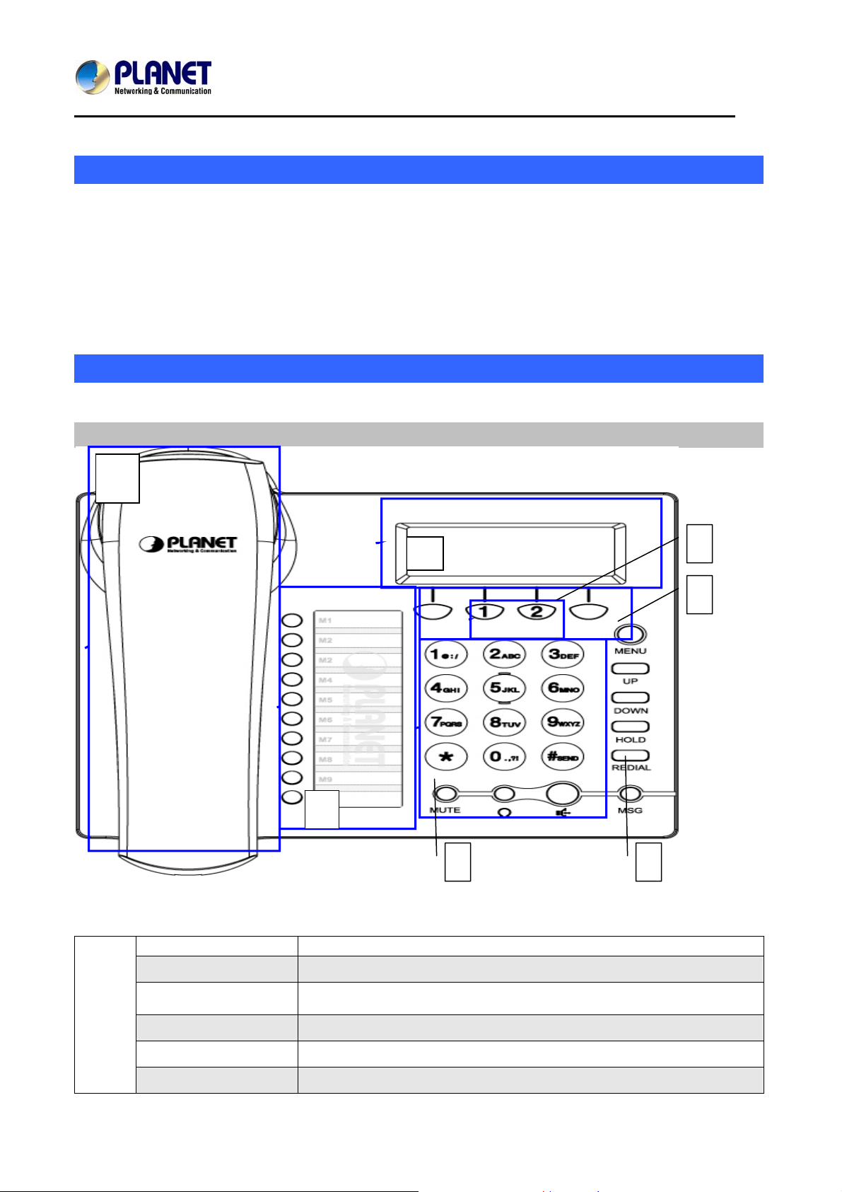
Physical Details
The following figure illustrates the front/rear panel of IP Phone.
Front View and Keypad Function
1
2
VIP-256T
4
5
Keypad Descriptions
Handset Top Cradle For the placement of handset (Receiver end)
1
Hook Switch For hang-up and hang-off of handset
Cradle Latch To prevent the handset from dropping when it is wall-mounted.
Handset Bottom Cradle For the placement of handset (Transmitter end)
Handset Cord Port RJ-11 jack on the left side of the IP phone
Headset Wired Port RJ-11 jack on the bottom of the handset
3
13
6
7
Page 14
SIP IP Phone
Headset To mount mouthpiece and earpiece on the single handle.
LCD Screen
2
Multi-Functional
3
Key
4
Line Keys
5
Soft Keys
The LCD screen is for displaying your settings, such as phone number,
line status and so on.
These keys can be used as speed dial, BLF, shortcut key, pick up and call
park.
In standby:
These keys are used as line keys; you can press the line button to select
the corresponding line, and then user can make call or do other functions.
The LEDs beneath the keys are used to display the status of each
extension.
These keys are used as soft keys. These can be used for item selection or
control on the LCD screen.
The Soft key function depends on their corresponding content displayed
on the LCD at that time.
VIP-256T
6
Numeric Keypad
Other Function and
7
Numeric keys
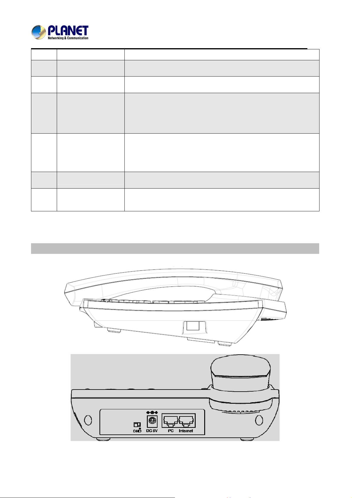
Rear View
Enters numeric digits for initiating a call or for entering configuration
information.
Include MENU, UP, DOWN, REDIAL, and Numeric Keys
14
Page 15
SIP IP Phone
Keypad Descriptions
1
Headset Headset console, connect to headset
2
DND Switch
3
DC 5V,1A Powe r port
4
PC Connects to a PC.
5
Internet Connects to the Ethernet switch, router or Internet.
VIP-256T
The switch is used to turn on or turn off DND.
Below the character “DND” is a dot.
When the switch is slided to the “dot” area, DND is on;
otherwise DND is off.
Taking the left picture for example, DND is on.
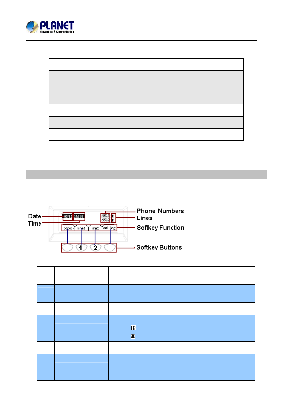
Phone Screen Features
This is what your main phone screen might look like with an active call.
Graphic Icon Descriptions
1
Date
2
Time
3
Phone Numbers
To display the current date.
Date format is mm/dd
To display the current time.
Time format is mm:ss (A or P)
To display the phone number of lines.
To display the status of lines.
4
Lines
5
Softkey Function
6
Softkey Buttons
The icon means unregistered.
The icon mean registered.
To display the current softkey function.
User can use the softkey button to highlight the item displayed on
the LCD screen and then configure.
One button directs to one softkey function, the blue line in the left
15
Page 16

SIP IP Phone
VIP-256T
picture displays the corresponding relationship.
16
Page 17
SIP IP Phone
VIP-256T
Chapter 2
Preparations & Installation
Physical Installation
VIP-256T: Enterprise SIP IP Phone (2 x RJ-45, 1 x Internet interface)
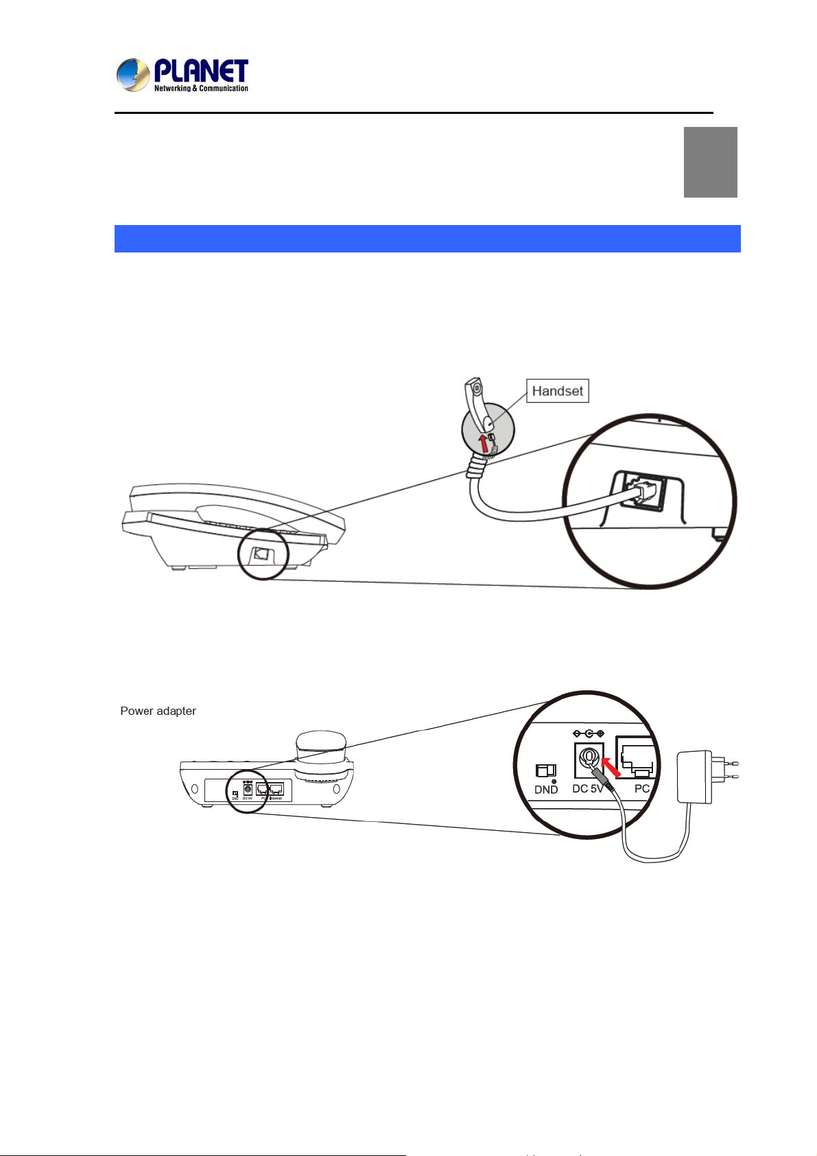
Step 1. Handset Connection
Plug one end of the handset cord into the handset and the other end into the phone body.
2
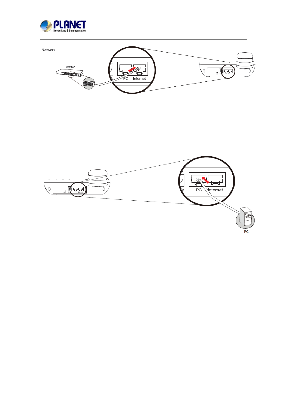
Step 2. Connecting Power Adapter and Network
Power Adapter
Network
17
Page 18
SIP IP Phone
VIP-256T
NOTE: Use only the power adapter shipped with the unit to ensure correct functionality
Step 3. Computer Network Setup
Set your computer’s IP address to 192.168.0.x, where x is a number between 2 to 254 (ex cep t 1 where
is being used for the IP Phone by default). If you don’t know how to do this, please ask your network
administrator.
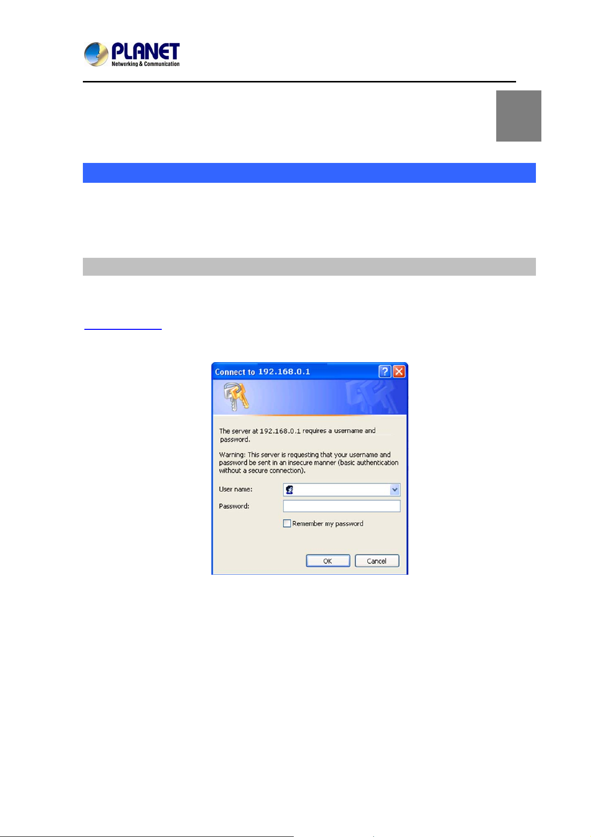
Step 4. Login Prompt
Use web browser (Internet Explorer 6.0 or above) to connect to 192.168.0.1 (type this address in the
address bar of web browser).
You’ll be prompted to input user name and password: admin and 123
18
Page 19
SIP IP Phone
VIP-256T
Administration Interface
The IP Phone provides GUI (Web based, Graphical User Interface) for machine management and
administration. Key pad administration also available for simple configuration.
Web Configuration Access
To start IP Phone web configuration, you must have one of these web browsers installed on computer
for management
• Microsoft Internet Explorer 6.0.0 or higher with Java support
Default IP address of IP Phone is 192.168.0.1. You may now open your web browser, and insert
http://192.168.0.1 in the address bar of your web browser to logon IP Phone web configuration page.
IP Phone will prompt for logon username and password, please enter: admin and 123 to continue
machine administration.
In order to connect machine for administration, please locate your PC in the same
network segment (192.168.0.x) of IP Phone. If you’re not familiar with TCP/IP, please
refer to related chapter on user’s manual CD or consult your network administrator
for proper network configurations.
19
Page 20
SIP IP Phone
VIP-256T
Chapter 3
Network Service Configurations
Configuring and Monitoring your IP Phone from Web Browser
The IP Phone integrates a web-based graphical user interface that can cover mo st configurations
and machine status monitoring. Via st andard, web browser, you can configure an d check machine
status from anywhere around the world.
Manipulation of IP Phone via Web Browser
Log on IP Phone via web browser
After TCP/IP configuration s on your PC, you may now open your web browser, and input
http://192.168.0.1
IP Phone will prompt for logon username and password: admin and 123.
to logon IP Phone web configuration page.
3
When users login the web page, users can see the IP Phone system information like firmware version,
company, etc on this main page.
20
Page 21

SIP IP Phone
VIP-256T
Chapter 4
VoIP IP Phone Status
Status
You can check the basic phone status to find out more information about the phone.
They include three parts: Basic, DHCP and Syslog.
Basic
Included on this page are Product Information, Line Status, Network Status, and System Status.
4
21
Page 22

SIP IP Phone
VIP-256T
Items
Product Information
Line Status
Network Status
System Status
Refresh
Descriptions
It shows the basic information of the product.
It shows the registration state of each line.
It shows the information of Internet port, VPN and PC port.
It shows the current time and the running time of the product.
Click Refresh button to refresh status of phone.
22
Page 23

SIP IP Phone
VIP-256T
DHCP
This page displays the status about DHCP server enable/disable, start IP address, end IP address and
client lease time. Click Refresh button to refresh status of DHCP server.
Item
DHCP Status
Descriptions
It shows the information of the DHCP Server.
Syslog
It shows all the log information of system.
23
Page 24

SIP IP Phone
VIP-256T
24
Page 25

SIP IP Phone
VIP-256T
Chapter 5
SIP Account Setting
SIP Account
SIP is a request-response protocol, dealing with requests from clients and responses from servers.
Participants are identified by SIP URLs. Requests can be sent through any transport protocol. SIP
establishes call parameters at either end of the communication, and handles call transfer and
termination.
SIP Setting
Set your SIP server in the following interfaces. These parameters are related to registration an d call.
5
Items
SIP T1
Max forward
SIP Reg User Agent
Descriptions
RFC 3261 T1 value (RTT estimate), which can range from 0 to 64 second.
Defaults to .5 seconds
SIP Max Forward value, which can range from 1 to 255. Defaults to 70.
User-Agent name to be used in a REGISTER request.
25
Page 26

SIP IP Phone
VIP-256T
Name
Max Auth
Make ALL A VT
Package
RFC 254.3 Call Hold
SRTP
SRTP Prefer
Encryto
If this is not specified, the <SIP User Agent Name> is also used for the RE
GISTER request. Defaults to blank
Maximum number of times (from 0 to 255) a request may be challenged.
Default is 2.
For second dial tone, enable this item package by making the position to 1,
but 0 for disabling this item.
If set to yes, unit will include c=0.0.0.0 syntax in SDP when sending a SIP
re-INVITE to the peer to hold the call. If set to no, unit will not include the c
=0.0.0.0 syntax in the SDP.
The unit will always include a=sendonly syntax in the SDP in either case.
Defaults to yes
Enable/Disable SRTP(Secure Real-time Transport Protocol)
SRTP encryption type.
NAT Setting
Set your NAT Traversal parameters in the following interface. It is helpful for the device behind NAT.
Item
Enable/Disable NAT.
Descriptions
NAT Traversal
STUN Server IP
NA T Re fresh Interv al (sec)
Port
VIP-256T supports STUN traversal. Choose “STUN” in the “NAT
Traversal Mode” if you want traverse NAT/Firewall.
STUN server IP address, default is stun.fwdnet.net
the interval to refresh
STUN port
26
Page 27

SIP IP Phone
VIP-256T
Line Settings
On this webpage, users can configure the information about SIP account1, including the following 4
parts: Basic, Audio Configuration, User and Advanced, user can program all the SIP parameters. For
VIP-256T, it can support 2 lines registered.
Basic
Set the basic information such as Phone Number, Account, Password, SIP Proxy and so on
provided by your VOIP Service Provider.
Items
Line Enable
Peer to Peer
Proxy DNS Type
Use VPN
Domain Name
SIP Server
SIP Port
Outbound Proxy
Outbound Port
Display Name
Descriptions
Enable/Disable SIP Line
Enable/Disable PEER to PEER
If enable, SIP line will not send register request to SIP server;
In System Status, SIP line Status is Registered;
SIP-1 can make call out, but others can not call SIP line.
Choose DNS type from A Type and DNS SRV.
Enable/Disable VPN
The domain of SIP Server
The IP address of SIP Server
The port which SIP Server supports for VOIP service, default is 5060
Outbound Proxy IP or domain name
Outbound Proxy’s Service port
The number will display in callee
Phone Number
Number of telephone provided by SIP Proxy
27
Page 28

SIP IP Phone
VIP-256T
Account
Password
SIP account provided by SIP Proxy
SIP password provided by SIP Proxy
Audio Configuration
Select the audio Codec you want to use.
Items
Audio Codec Type1
Choose the audio codec type from G.711U, G.711A, G.722, G.729,
Descriptions
Audio Codec Type2
Audio Codec Type3
Audio Codec Type4
Audio Codec Type5
G.723 Coding Speed
Packet Cycle
G.723
Choose the audio codec type from G.711U, G.711A, G.722, G.729,
G.723
Choose the audio codec type from G.711U, G.711A, G.722, G.729,
G.723
Choose the audio codec type from G.711U, G.711A, G.722, G.729,
G.723
Choose the audio codec type from G.711U, G.711A, G.722, G.729,
G.723
Choose the speed of G.723 from 5.3kbps and 6.3kbps
The RTP packet cycle time
28
Page 29

SIP IP Phone
VIP-256T
Supplementary Services Subscription
Call Waiting - This call feature allows your phone to accept other incoming calls during the
conversation.
Items
Call Waiting
Call Pickup
Delayed Hot Line
MWI Enable
Voice Mailbox
Numbers
Enable / Disable Call Waiting.
Enable / Disable Call Pickup.
Fill in the hotline number.
Pick up handset or press speaker/headset button, VIP-256T will
dial out the hotline number automatically. Ex: xxxT4 will delay 4
seconds, then transfer to xxx (set to T0 will not delay.)
Enable / Disable MWI (message waiting indicate).
Fill in the voice mailbox phone number
Descriptions
Advanced Setup
IP phone makes calls based on SIP accounts. IP phone can support 4 independent SIP accounts, and
each account can be configured to different SIP servers.
29
Page 30

SIP IP Phone
VIP-256T
Items
Domain name
Mode
Carry Port
Information
Signal Port
DTMF Type
RFC2833 Payload
(>=96)
Register Refresh
Interval
RTP Port
Cancel Message
Enable
Descriptions
If or not use domain name in the SIP URI
If or not carry Port information in the SIP URI.
The default of the local port of SIP protocol is 5060
Choose the DTMF type from IN_band, RFC2833 and SIP INFO.
User can use the default setting
The interval between two normal Register messages. You can u se the
default setting.
Set the port to send RTP.
IP Phone will select one idle port for RTP if you set “0”, otherwise use
the value user set.
When you set enable, an unregistered message will be sent before
registration, while you set disable, unregistered message will not be
sent before registration. You should set the option for different Proxy.
Prack Enable
SIP Ping Enable
Keep-Alive Interval
(10-60s)
Enable / Disable prack.
If this option enable, IP Phone will send SIP-PING to Server periodically
instead of sending hello packet. The send interval is Keep-alive interval.
The interval that IP Phone will send an empty packet to Proxy.
30
Page 31

SIP IP Phone
VIP-256T
Chapter 6
Basic
In this item you can program all the Network parameters.
Network Setting
6
31
Page 32

SIP IP Phone
Internet Port (WAN)
Internet Port WAN (Static IP)
VIP-256T
Items
Internet Connection
Type
IP Address
Subnet Mask
Default Gateway
Primary DNS
Second DNS
Internet Connection
Type
Internet Port WAN (DHCP)
Descriptions
Choose Static IP.
The IP address of Internet port
The subnet mask of Internet port.
The default gateway of Internet port.
The primary DNS of Internet port.
The second DNS of Internet port.
Choose Static IP.
Items
Internet Connection
Type
DNS type
Descriptions
Choose Automatic Configuration-DHCP.
Choose DNS type from Manual to Automatic
1. In Manual: user should set the Primary DNS and Second DNS
32
Page 33

SIP IP Phone
manually.
2. In Automatic: IP Phone will get the Primary DNS and Second DNS
from DHCP Server automatically.
Internet Port WAN (PPPoE)
VIP-256T
Item
Internet Connection
Type
PPPoE Account
PPPoE Password
PPPoE Auto-Dial
DNS Type
Primary DNS
Second DNS
Descriptions
Choose PPPoE.
Fill in the PPPoE account obtained from Internet Service Provider
Fill in the PPPoE account obtained from Internet Service Provider
Enable / Disable PPPoE Auto-Dial.
Choose DNS type from Manual to Automatic
1. In Manual: user should set the Primary DNS and Second DNS
manually.
2. In Automatic: IP Phone will get the Primary DNS and Second DNS
from DHCP Server automatically.
The primary DNS of Internet port.
The second DNS of Internet port.
33
Page 34

SIP IP Phone
PC Port (LAN)
Support three modes : disable, NAT and Bridge
VIP-256T
Items
PC Port
Connection T ype
Local IP Address
Subnet Mask
Descriptions
Choose the PC port connection type from disable, NAT and Bridge.
NAT - The product is the same as a router.
Bridge - The LAN port is same as the WAN port
Disable - PC port switch to NAT mode, but Internet port and PC port
can’t communication to each other.(The device behind the PC port still
can connect to each other)
Set the IP address of PC port.
Efficient when user choose NAT.
Set the subnet mask of PC port.
Efficient when user choose NAT.
34
Page 35

SIP IP Phone
VIP-256T
Network Address Server Settings (DHCP)
Support three modes: disable, NAT and Bridge
DHCP Server - It will assign the IP Addressed set here to devices that connect to the LAN port.
Number of Address - You may limit the number of addresses your router hands out.
Items
Local DHCP
Server
Start IP Address
Number of
Address
Client Lease Time
Primary DNS
Secondary DNS
Local DHCP
Descriptions
Enable / Disable DHCP Server.
If PC port is not in NAT mode, user can not enable DHCP server.
The starting IP address which IP phone will attribute to clients.
Note: The Network Sect of DHCP Server Start Address should be the
same as VIP-256PT’s PC port. Generally speaking, you can use the
default setting.
Number of IP address will distribute to clients.
The interval of DHCP will send request to continue in period of validity.
Unit is hour.
Primary DNS that DHCP Server will distribute.
You can use the default setting.
Secondary DNS that DHCP Server will distribute.
You can use the default setting.
Enable / Disable DHCP Server.
Server
If PC port is not in NAT mode, user cannot enable DHCP server.
35
Page 36

SIP IP Phone
VIP-256T
MAC Address Clone
MAC Address Clone: Some ISPs will require you to register your MAC address. If you do not wish to
re-register your MAC address, you can have the router clone the MAC address that is registered with
your ISP.
Items
MAC Clone
MAC Clone Step
Descriptions
MAC is the hardware address of network equipment. Sometimes,
network providers may bind network account with the network
equipment’s MAC address. So you may not pass the provider’s
authentication when you use a new VIP-256T. In this case, you can use
MAC Clone to copy your PC’s MAC address to VIP-256T’s Internet
port.
MAC is an important parameter for network equipment, so you should
make sure that the MAC is right, in order to prevent to make VIP-256T
unusable.
You can login VIP-256T’s Web via PC port if you are incautious about
making it wrong. And then cloning the right MAC or resuming the
default settings.
Step 1 Press button to get the PC’s MAC
address
Step 2 Press to save the changes
Step 3. Press to cancel MAC address clone.
Step 4. Press Reboot to reboot VIP-256T.
36
Page 37

SIP IP Phone
VIP-256T
VPN
A Virtual Private Network (VPN) is the extension of a private network that encompasses links across
shared or public networks like the Internet. In short, by VPN technology, you can send data between
two computers across a shared or public network in a manner that emulates the properties of a
point-to-point private link.
Items Descriptions
VPN Enable
Initial Service IP
Initial Service
Port
User Name
Password
Route Strategy
Enable / Disable VPN.
And user can choose the VPN mode from PPTP and L2TP.
VPN server IP address.
VPN server port.
The user name for authentication.
Password for authentication.
Choose route mode from All or SIP.
37
Page 38

SIP IP Phone
VIP-256T
DMZ
Enabling this option will expose the specified host to the Internet. All ports between the DMZ Start Port
and the DMZ End Port will be accessible from the Internet.
Items Descriptions
Use DMZ
DMZ Host IP
Address
DMZ Start Port
DMZ End Port
DMZ Example:
For example, the DMZ computer’s IP is “192.168.1.2”. “DMZ start port” and “DMZ end port” are 20
and 1023. The DMZ function is that DMZ computer can get the requests from the ports (20 to 1023)
of VIP-256T’s Internet port.
Enable / Disable DMZ
set the IP address of DMZ host
set the start port of DMZ host
set the end port of DMZ host
38
Page 39

SIP IP Phone
QoS
Layer 3 QoS: Set the IP TOS value of SIP and RTP Packets.
Layer 2 Qos: Set the value of 802.1Q and 802.1p priority
VIP-256T
Items Descriptions
Some ISP supply QoS services. The QoS services can make the best of improving the quality of
Voice application. You can get the settings from the ISP if they supply QoS services. Please contact
them if you need it.
39
Page 40

SIP IP Phone
VIP-256T
Chapter 7
Phone Configurations
Performance
User can configure the value of ring volume, speakerphone volume, handset volume and so on.
Volume
Volume Settings - Adjust the input gain or the volume of handset/speaker/ring
Items Descriptions
7
Handset Input
Gain
Handset Volume
Gain
Speakerphone Input
Gain
Speaker Volume
Ringer Volume
Adjust the handset input gain from 0-7
Adjust the output gain from 0-7
Adjust the speakerphone input gain from 0-7
Adjust the speaker volume from 0-7
Adjust the ringer volume from 0-7.
40
Page 41

SIP IP Phone
Regional
Modification of the Tone type and tone parameters.
Items Descriptions
VIP-256T
Tone Type
Min Jitter Delay (ms)
Max Jitter Delay (ms)
Hook-On Tone Delay
(sec)
Ringing Time(Sec)
Busy Tone
Delay(Sec)
Choose tone type from China, US, Hong Kong and Korea. Besides
custom types, the other types are already defined in the system.
The min. value of VIP-256T’s jitter delay, VIP-256T’s jitter is an
adaptive jitter mechanism.
The max. value of VIP-256T’s jitter delay, VIP-256T’s jitter is an
adaptive jitter mechanism.
How long VIP-256T will delay to sound hook-on tone when call party
end call.
How long VIP-256T will ring
Before the busy tone VIP-256T will send the delay tone (like di,di.), this
parameter define how long the delay tone is.
41
Page 42

SIP IP Phone
VIP-256T
Call Forward
Call Forward - This feature allows you to forward an incoming call to another phone number.
Items Description
The phone number which will be forwarded to.
All Forward
Busy Forward
No Answer Forward
No Answer Timeout
IP Phone will forward all calls to the phone number immediately when
there is an incoming call.
The phone number which will be forwarded to when line is busy.
The phone number which will be forwarded to when there's no answer
at your phone.
The seconds to delay forwarding calls, if there is no answer at your
phone.
Miscellaneous
Auto Answer - All the incoming calls will be put through automatically.
Items Description
Auto Answer
Dial Time Out
Call Immediately Key
ICMP Ping
Enable / Disable auto answer. If enable, VIP-256T will auto answer all
incoming call immediately.
How long VIP-256T to sound dial out tone when VIP-256T dialing
number.
Choose call immediately key form * or #.
Enable / Disable ICMP Ping.
If enable this option, VIP-256T will ping the SIP Server every interval
time; otherwise, It will send “hello” empty packet to the SIP Server.
42
Page 43

SIP IP Phone
VIP-256T
Handsfree Key
Mode
Choose the handsfree key mode from handsfree and headset.
Multi-Functional Key
In here user can program the Multi-Function Key like Speed dial , BLF, Shortcut Key, Call Pick up
Items Descriptions
Program Step:
Step 1.Choose one current key board to configure from Basic Board, Expansion Board 1,
Expansion Board 2, Expansion Board 3, Expansion Board 4, Expansion Board 5 and Expansion
Board 6.
Step 2.Choose one Exp Key from Exp Key 1 to Exp Key 20.
Step 3.Choose one function type from Speed Dial, BLF, Shortcut Key and Call Pick Up.
Step 4.Set the other corresponding parameters.
Step 5.Press Save Settings button to save changes, press Cancel Changes button to cancel
changes.
Adding speed dial:
Speed Dial: You can configure the key as simplified speed dial key.This key function allows you to
easily access the most frequently dialed numbers.
43
Page 44

SIP IP Phone
VIP-256T
1. Choose one Exp Key to configure
2. Select the speed dial from the drop down list
3. Choose the Line from auto (the first line registered), line1, line2, line3, line 4 and line 5
4. Fill the phone number in Expansion
5. Press to save changes and you can see the status of corresponding LED is
solid green.
6. Press button to make changes effective.
If set properly, press the corresponding key to make call immediately, and the status of LED is
solid red.
Adding BLF:
BLF: The button can be configured to Busy Line Field function with specified account. This
feature must be supported by the sip server.
1) Choose one Exp Key to configure
2) Select the BLF from the drop down list
3) Choose the Line from line 1, line2, line3, line 4 and line 5.
4) Fill the monitored phone number in Expansion
5) Fill the pickup code in Pickup Code if user wants to pickup the call when there is a new call
coming in monitored phone.
6) Press
to save changes and you can see the status of correspond ing LED is
solid green.
7) Press
button to make changes effective.
Adding shortcut key:
Shortcut Keys: Shortcut Keys are predefined shortcuts to phone and call functions.
1. Choose one Exp Key to configure
2. Select the shortcut key from the drop down list
3. Select the mode from the phonebook, call history, text message, volume+, volume- and
login/logout in the drop down list.
4. Press to save changes and you can see the status of correspond ing LED is
44
Page 45

SIP IP Phone
VIP-256T
solid green.
5. Press button to make changes effective.
6. If set properly, press the corresponding button to access to phonebook, call history, text
message, volume+, volume- and login/logout menu directly.
Adding call park:
1. Choose one Exp Key to configure
2. Select the Call Park from the drop down list in type
3. Choose the Line from line1, line2, line3, line 4 and line 5.
4. Fill the pickup extension code in Expansion
5. Press
solid green.
6. Press
Dial Plan
to save changes and you can see the status of correspond ing LED is
button to make changes effective.
Dial Plan
Line
Digit Map
Items Descriptions
Enable / Disable dial rule.
Choose the call mode from line1, line2, line3, line4 and line5.
Fill in the sequence used to match input number
45
Page 46

SIP IP Phone
VIP-256T
Action
Move Up
For the syntactic, please refer to the following Dial Plan Syntactic
Choose the dial plan mode from Deny and Dial Out.
Deny means VIP-256T will reject the matched number, while Dial Out
means VIP-256T allow dial out the matched number.
Press it to move up.
Items Descriptions
Adding one dial plan:
Step 1. Enable Dial Plan
Step 2. Click Add button, and the configuration table
Step 3. Fill in the value of parameters.
Step 4.Press OK button to end configuration.
Step 5. Press Save Settings button to save changes.
Editing one dial plan:
Step 1. Enable Dial plan
Step 2. Choose one dial plan
46
Page 47

SIP IP Phone
Step 3. Click Edit button, and the configuration table
Step 4. Change the value of parameters.
Step 5.Press OK button to end configuration.
Step 6. Press Save Settings button to save changes.
Deleting one dial plan:
Step 1. Enable Dial plan
Step 2. Choose one dial plan
Step 3. Click Delete button to delete the dial plan
Dial Plan Syntactic
Items Descriptions
VIP-256T
0 1 2 3 4 5 6 7 8 9 * #
X
[sequence]
x.
<dialed: substituted>
x,y
Legal characters
Lowercase letter x stands for one legal character
To match one character form sequence.
For example:
1. [0-9]: match one digit form 0 to 9
2. [23-5*]: match one character from 2 or 3 or 4 or 5 or *
Match to , , , …...
For example:
“01.”: can match ”0”, “01”, “011”, ”0111”, …….., ”01111…”
Replace dialed with substituted.
For example:
<8:1650>123456:input is “85551212”, output is“16505551212”
Make outside dial tone after dialing “x”, stop until dialing character “y”
For example:
“9,1xxxxxxxxxx”:VIP-256T make outside dial tone after inputting “9”,
stop tone until inputting “1”
“9,8,010x”: make outside dial tone after inputting “9”, stop tone until
inputting “0”
Set the delayed time.
For example:
T
“<9:111>T2”: VIP-256T will dial out the matched number “111” after 2
seconds.
47
Page 48

SIP IP Phone
VIP-256T
Items Descriptions
Example 1
If user dials #12#2, VIP-256T will call 010#12%232 immediately.
Example 2
If user dials 5,8101, VIP-256T will call 2413338101 immediately,
And VIP-256T will make outside dial tone after inputting “5”, stop tone until inputting “8”.
Example 3
If user dials 422xxxx or 522xxxx, VIP-256T will call 22xxxx333 immediately.
Example 4
If user dials 2,622 or 2,6222 or 2,62222 or or ,
VIP-256T will call 5622 or 56222 or 562222 or or immediately.
And VIP-256T will make outside dial tone after inputting “2” or “3”, stop tone until inputting “6”.
Example 5
If user dials
, VIP-256T will reject the phone number.
48
Page 49

SIP IP Phone
VIP-256T
Phonebook
Phonebook
The list shows all the directory entries. Please click "Save Settings" button to save this li st after you edit
or add an item.
Items Descriptions
Name
Number
Input the name
Input the phone number
Items Descriptions
Adding one phone book:
Step 1. Click Add button, and the configuration table
Step 2. Fill in the value of parameters.
Step 3. Press OK button to end configuration.
49
Page 50

SIP IP Phone
Step 4. Press Save Settings button to save changes.
Editing one phone book:
Step 1. Choose one phone book
Step 2. Click Edit button, and the configuration table
Step 3. Change the value of parameters.
Step 4. Press OK button to end configuration.
Step 5. Press Save Settings button to save changes.
Deleting one phone book:
Step 1. Choose one phone book
Step 2. Click Delete button to delete the phone book
Move one phone book to Black list:
Step 1. Choose one phone book
Step 2. Click Move to blacklist button to delete the phone book
VIP-256T
Black List
Calls from this list cannot get through.
Items Descriptions
Name
Number
Input the name
Input the phone number
50
Page 51

SIP IP Phone
Items Descriptions
Adding one Black List:
Step 1. Click Add button, then the configuration table.
Step 2. Fill in the value of parameters.
Step 3. Press OK button to end configuration.
Step 4. Press Save Settings button to save changes.
Editing one Black List:
Step 1. Choose one black list
Step 2. Click Edit button, and the configuration table
Step 3. Change the value of parameters.
Step 4. Press OK button to end configuration.
Step 5. Press Save Settings button to save changes.
Deleting one Black List:
VIP-256T
Step 1. Choose one black list
Step 2. Click Delete button to delete the black list
Moving one Black List to phonebook:
Step 1. Choose one black list
Step 2. Click button to move the black list to the phonebook
Call Log
To view the call log information such as redial list (incoming call), answered call and missed call
51
Page 52

SIP IP Phone
VIP-256T
Chapter 8
VoIP IP Phone Administration
8
Management
On this page, configuration of the value of Time/Date, password, web access, and system log and so
on is made.
Time/Date
Items Description
NTP Server
Time Zone
Manual Time
Alarm Enable
Alarm Time
Fill in the NTP server IP address or Domain name
Choose the time zone
Adjust time by manual
If or not enable alarm
Set alarm time
Daylight Saving
Time
Offset
Start Month
Start Day of Week
Start Day of Week
Last in Month
Start Hour of Day
Stop Month
Stop Day of Week
Stop Day of Week
Last in Month
Stop Hour of Day
If or not enable daylight saving time.
Offset time, “-60” means advancing 60miniter, “60” means delaying
60minite
Choose starting month
Choose starting day
Choose starting week
Choose starting hour
Choose stopping month
Choose stopping day
Choose stopping week
Choose stopping the function hour
52
Page 53

Items Descriptions
Alarm Setting:
SIP IP Phone
VIP-256T
Step 1. Enable alarm
Step 2.Set alarm time
Step 3. Press Save Settings button to save changes and then press Reboot button to active
changes
Items Descriptions
Daylight Saving Time:
Step 1. Enable Daylight Saving Time.
Step 2. Set value of offset,
Step 3: Set staring Month/Week/Day/Hour in Start Month/Start Day of Week Last in
Month/Start Day of Week/Start Hour of Day, analogously set stopping
Month/Week/Day/Hour in Stop Month/Stop Day of Week Last in Month/Stop Day of
Week/Stop Hour of Day.
Step 5.Press Saving Settings button to save and press Reboot button to active changes.
53
Page 54

Password Reset
Items Descriptions
SIP IP Phone
VIP-256T
User Type
Original Password
New Passwo rd
Password Confirm
Items Descriptions
Change the password:
Choose the user type from admin and user.
Input original password
Input the new password
Input the new password again
Step 1. Choose the admin from the drop-down list.
Step 2. Input original password, default setting is null.
Step 3. Input a new password twice time in New Password and Confirm
54
Page 55

Web Access
Items Description
SIP IP Phone
VIP-256T
WAN Interface
Login
Web Login Port
Web Idle Timeout
If or not enable user login WEB via Internet port.
If enable, user can access Web to administration.
Set the port which used to login WEB via Internet port and PC port,
Default is 8080, that is why URL should have 8080.
Set the web idle timeout time.
The web page can be logged out after Web Idle Timeout without any
operation.
System Log Setting
Items
SysLog Server
Log Level
Descriptions
Set the SysLog Server IP address or domain name for VIP-256PE.
Choose log level from None/Error/Warn/INFO/Debug.
The priority changes from left to right, left is the lowest, right is the
highest; the higher priority, the more information in syslog.
55
Page 56

SIP IP Phone
Local and remote Syslog
In local:
Step 1. Set syslog server null and choose one kind of Log Level.
Step 2. Press Saving Settings button to save and press Reboot button to active changes.
VIP-256T
Step 3. User can view syslog in Status/Syslog webpage.
In remote:
Step 1. Fill in syslog server IP address or domain name
Step 2. Choose one kind of Log Level.
Step 3. Press Saving Settings button to save and press Reboot button to active changes.
Step 4. User can view syslog in syslog server, and you can also view the syslog in
Status/Syslog webpage.
56
Page 57

Factory Defaults
Items Description
SIP IP Phone
VIP-256T
Factory Default
Press Factory Default button to set VIP-256PE to default.
Updating Firmware
Click on the Browse button to select the firmware file to be uploaded to the router.
Security
CA Certificate - The issuer of the certificate.
Client Certificate - user's certificate issued by CA.
Private Key - user's private key file.
57
Page 58

SIP IP Phone
Items Description
VIP-256T
TR069 CA Certificate
TR069 Client
Certificate
TR069 Private Key
Provision CA
Certificate
Provision Client
Certificate
Provision Private Key
The CA certificate file of TR069
The Client Certificate file of TR069
The Private Key file of TR069
The CA certificate file of provision
The Client Certificate file of provision
The Private Key file of provision
Upload TR069 and Provision
User can upload cert files for TR069 and Provision as follows:
Step 1. Choose one File Type from
Step 2. Press
Step 3. Press
Next is the webpage where all files have well been uploaded.
to browser file.
to start upgrading.
.
58
Page 59

SIP IP Phone
VIP-256T
Provision
Provision allows a device automatically resync to a specific configuration file on a TFTP server or a web
server which use HTTP or HTTPS.
1) Provisioning allow VIP-256T auto-upgrading or auto-configuring
2) VIP-256T supports 3 ways to provision: TFTP, HTTP and HTTPS.
Before testing or using TFTP, user should have TFTP server and upgrading file and configuring
file.
Before testing or using HTTP, user should have HTTP server and upgrading file and configuring
file.
Before testing or using HTTPS, user should have HTTPS server and upgrading file and
configuring file and CA Certificate file(should same as https server’s) and Client Certificate file and
Private key file
3) User can uploading CA Certificate file and Cli ent Certificate file and Private Key file on Equipment
Manage/Cert Manage page.
59
Page 60

SIP IP Phone
Items Descriptions
VIP-256T
Provision Enabled
Resync On Reset
Resync Random
Delay
Resync Periodic
Resync Error Retry
Delay
Forced Resync
Delay
Resync After
Upgrade Attempt
Profile Rule
Phone Num1 for
Config
If or not enable provision
If or not enable resync after VIP-256T restart
Set the maximum delay for request the synchronization file
Set the periodic time for resync, default is 3600s
If the last resync was failure, VIP-256T will retry resync after the
“Resync Error Retry Delay” time, default is 3600s
If it’s time to resync, but VIP-256T is busying now, in this case,
VIP-256T will wait for a period time, the longest is “Forced Resync
Delay” , default is 14400s, when the time over, VIP-256T will forced to
resync
If or not enable
firmware upgrade after resync, “yes” is enable
URL of profile provision file
The first phone number which used to reboot VIP-256T in remote.
Phone Num2 for
Config
Auto-upgrade
Enabled
Auto-upgrade Error
Retry Delay
Upgrade Rule
The second phone number which used to reboot VIP-256T in remote.
If or not enable firmware upgrade.
Set the time to retry upgrade, effective when the last upgrade was
failure
URL of upgrade file
60
Page 61

SIP IP Phone
VIP-256T
61
Page 62

SIP IP Phone
SNMP
Allow the device to be managed by the Manager which is set in the SNMP Manager IP.
Items Descriptions
VIP-256T
SNMP Enable
Get Community
Set Community
SNMP Manager IP 1-4
If or not enable SNMP
String, as an express password between management process and the
agent process
String, as an express password between management process and the
agent process
The IP address of SNMP Manager
62
Page 63

SIP IP Phone
TR 069
Allow the device to be managed by the ACS server which is set in the ACS URL.
VIP-256T
Items Descriptions
TR069 Enable
CWMP
ACS URL
User Name
Password
Periodic Inform
Enable
Periodic Inform
Interval
User Name
Password
SSL Key
If or not enable TR069
If or not enable TR069
The URL of TR069 server
The VIP-256T’s user name for connecting to TR069 server
The VIP-256T’s password for connecting to TR069 server
If or not enable periodic information
The interval to send information to TR069 server
The TR069 server’s user name for connecting to VIP-256T
The TR069 server’s password for connecting to VIP-256T
Fill in SSL key.
63
Page 64

SIP IP Phone
VIP-256T
Appendix A -- Frequently Asked Questions
Q1: No Operation after Power On?
A1: Check if the power adapter is properly connected.
Q2: No Dial Tone?
A2: Check if the handset cord is properly connected.
Q3: Cannot Make a Call?
A3: Check the status of your SIP registration status or contact your administrator, supplier, or ITSP for
more information or assistance.
Q4: Cannot Receive Any Phone Call?
A4 : Check the status of your SIP registration status, or contact your administrator, supplie r, or ITSP for
more information or assistance
Q5: No Voice during an Active Call?
A5: Check if the servers support the current audio codec type, or contact your administrator, supplier,
or ITSP for more information or assistance.
Q6: Cannot connect to the configuration Website?
A6: Check if the Ethernet cable is properly connected.
Check if the URL is correctly written. The format of URL is: http:// the Internet port IP address
Check if your firewall/NAT settings are correct.
Check if the version of IE is IE8, or use other browser such as Firefox or Mozilla, or contact your
administrator, supplier, or ITSP for more information or assistance.
Q7: Forget the Password?
A7: Default password of website and menu is null.
If user changed the password and then forgot it, you cannot access to the configuration website or the
menu items which need password.
Solution:
Factory default: press Menu button and choose 16Factory Default, then a notice will appear, choose
OK by using the corresponding softkey button.
If you choose factory default, you will return the phone to the original factory settings and will erase ALL
current settings, including the directory and call logs.
Q8: How to switch to a different line to dial out?
A8: Before dialing out, press the correspondence line number you want to use, eg.,want to use Line 4
64
Page 65

SIP IP Phone
VIP-256T
to dial out, must press 2 to switch to line 2, then dial out.
Q9: Why my MSG light would not show any information when I receive the message?
A9: In SIP accounts / Lines / Supplementary service
Please enable the MWI (Message Waiting Indicate) a nd in Voice Mailbox numbers, please also assign
the Voice mail number.
65
Page 66

EC Declaration of Conformity
For the following equipment:
*Type of Product
*Model Number : VIP-256T / VIP-256PT
* Produced by:
Manufacturer‘s Name : Planet Technology Corp.
Manufacturer‘s Address: 10F., No.96, Minquan Rd., Xindian Dist., New Taipei City 231,
Taiwan (R.O.C.)
is hereby confirmed to comply with the requirements set out in the Council Directive on the
Approximation of the Laws of the Member States relating to Electromagnetic Compatibility
Directive (2004/108/EC), For the evaluation regarding the Electromagnetic Compatibility
(2004/108/EC), the following standards are applied:
Responsible for marking this declarati o n i f the:
⌧ Manufacturer Authorized representative established within the EU
Authorized representative established within the EU (if applicable):
Company Name: Planet Technology Corp.
Company Address: 10F., No.96, Minquan Rd., Xindian Dist., New Taipei City 231, Taiwan
Person responsible for making this declaration
Name, Surname Jonas Yang
Position / Title : Product Manager
Taiwan
Place Date Legal Signature
: 802.3af PoE SIP IP Phone (2-Line)
EN 5502 2006+A1:2007
EN 55024 1998+A1:2001+A2:2003
EN 61000-3-2 2006+A2:2009
EN 61000-3-3 2008
(R.O.C.)
30th Mar., 2012
PLANET TECHNOLOGY CORPORATION
e-mail: sales@planet.com.tw http://www.planet.com.tw
10F., No.96, Minquan Rd., Xindian Dist., New Taipei City 231, Taiwan (R.O.C.)
Tel:886-2-2219-9518 Fax:886-2-2219-9528
 Loading...